


Please contact the TRT service department if you have any questions about your trailer. Please list the model number and Vehicle Identification Number (VIN) in all correspondence.
Contact your local distributor.
Supplied Trailer Information
Supplied documentation (electronic) comprises the following: Operating Procedure, Risk Analysis, Rated Capacity, Parts Catalogue and Service Manual.
Any modifications made to the Trailer must be approved by manufacturer. Failure to gain written approval will void warranty.
Vehicle Identification Number (VIN)
When corresponding with the manufacturer the VIN should be included, it will be used to identify the trailer. (VIN is located at the front of the trailer.)
Manufacturer
TRT Tidd Ross Todd Ltd 48 Maui Street
Pukete Industrial Estate
Hamilton 3200, New Zealand
Phone: +64 7 849 4839
Fax: +64 7 849 3628 trailers@trt.co.nz www.trt.co.nz
TRT Australia 1028 Lytton Road, Murarrie, QLD 4172
Australia
Phone: +61 7 3890 8800
AU Parts: parts@trtaust.com.au
AU Service Group: service@trtaust.com.au www.trtaustralia.com.au
4.3.5
5.
5.8
6.
7.
8.
VIN
5-LINE A TRAILER:
7A9AS0485RH002001 MODEL: PF5H120FOD
3-LINE MODULE:
7A9AS0485RH002002 MODEL: PF3H54FOD
2-LINE MODULE #1:
7A9AS0485RH002003 MODEL: PF2H36FOD
2-LINE MODULE #2:
7A9AS0485RH002004 MODEL: F2H36FOD
TARE WEIGHT: (Incl Ramp)
5-Line (Lead Trailer Only)
7-Line (5+2)
8-Line (5+3)
9-Line (5+2+2)
10-Line (5+2+3)
12-Line (5+2+2+3)
Ramps 2500kg
GVM RATING:
5-Line (Lead Trailer Only) –
7-Line (5+2)
8-Line (5+3)
9-Line (5+2+2)
10-Line (5+2+3)
12-Line (5+2+2+3) 216,000kg
AXLE RATING 16 tonne per line on highway 25 tonne per line below 8kph
DECK LENGTH (Behind Gooseneck): 25.752m
DECK HEIGHT: 865mm Lowered 1000mm Travel Height 1510mm Raised
AXLE SPACING:
5 - Line (A Trailer)
7 - Line (5+2)
8 - Line (5+3)
9 - Line (5+2+2)
10 - Line (5+3+2)
12 - Line (5+3+2+2)
Steer Axis 62% of combined trailer length
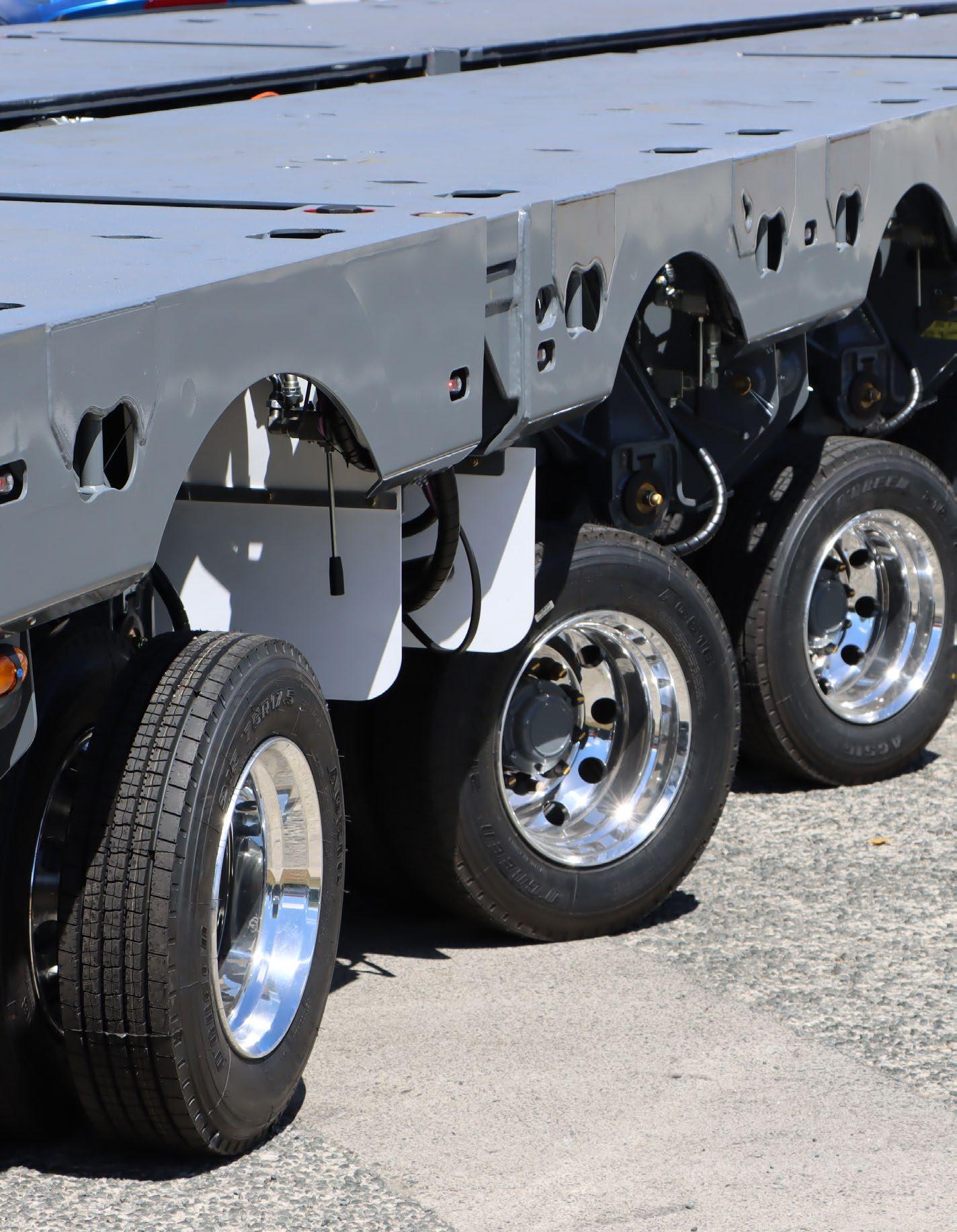
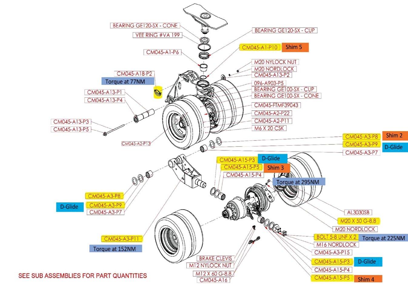
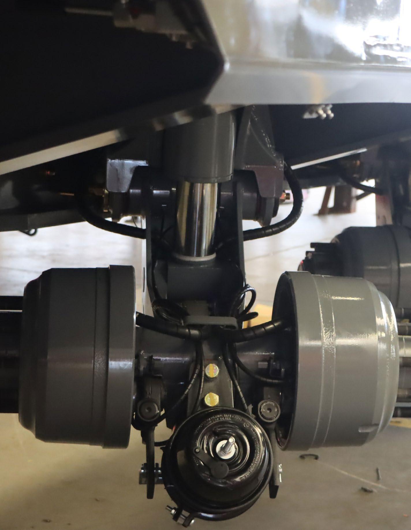
3.2 Wheel Assembly
4.1 Electrical
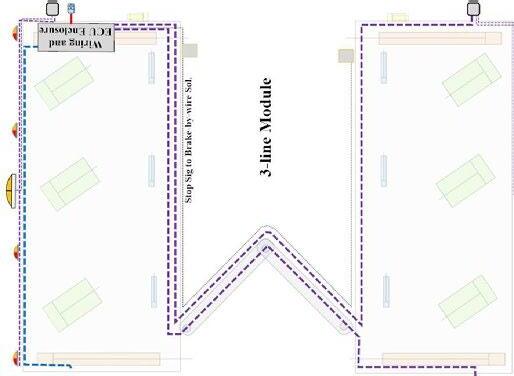
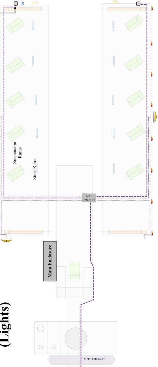
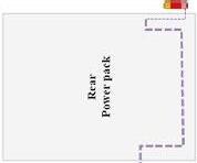
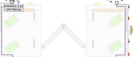
4.1.1 Trailer Plan View
WIRING LOOMCOMPUTER
WIRING LOOMLIGHTS
SUSPENSION & STEERING VALVES
ELECTRICAL ENCLOSUREREMOTE RECEIVER2x COMPUTER
POWERPACK1x 24V BATTERY (COMPUTER)1x 12V BATTERY (MOTOR START)
Inputs
NameAssignmentPin
IN_75
Frequency NPN
A Controller INPUTs and OUTPUTs
RC28-14/30 Controller
109Wheel Speed Sensor #1 Pulses per Rev 80, Wheel Diameter 215/75R17.5, Wabco Sensor Prt No ??
IN_73 Frequency NPN 110Wheel Speed Sensor #2
IN_52 Current 0- 20 mA138A1_LH_Steer_Signal
IN_53 Current 0- 20 mA168A1_RH_Steer_Signal
IN_54 Current 0- 20 mA218A2_LH_Steer_Signal
IN_55 Current 0- 20 mA229A2_RH_Steer_Signal
IN_56 Current 0- 20 mA171A3_LH_Steer_Signal
Pulses per Rev 80, Wheel Diameter 215/75R17.5, Wabco Sensor Prt No ??
IN_57 Current 0- 20 mA227A3_RH_Steer_Signal 4-20 mA Temposonic 220 mm stroke
IN_58 Current 0- 20 mA167A4_LH_Steer_Signal
IN_59 Current 0- 20 mA169A4_RH_Steer_Signal
IN_1 Voltage 0-5 volts 250Hydraulic Pressure Sensor
IN_2 Dig IN 236Local Control Selector
IN_3 Dig IN 209Remote Control Selector
IN_4 Dig IN 147Gooseneck up PB
IN_5 Dig IN 223Gooseneck down PB
IN_6 Dig IN 148Suspension Left Up PB
IN_7 Dig IN 159Suspension Left Down PB
IN_8 Dig IN 158Suspension Right Up PB
IN_9 Dig IN 214Suspension Right Down PB
IN_10 Dig IN 157Widening A Front LHS IN PB
IN_11 Dig IN 252Widening A Front LHS OUT PB
IN_12 Dig IN 238Widening A Rear LHS IN PB
IN_13 Dig IN 222Widening A Rear LHS OUT PB
IN_14 Dig IN 210Widening A Front RHS IN PB
IN_15 Dig IN 136Widening A Front RHS OUT PB
IN_16 Dig IN 137Widening A Rear RHS IN PB
IN_17 Dig IN 135Widening A Rear RHS OUT PB
IN_18 Dig IN 134Spare Input 1
IN_19 Dig IN 211Spare Input 2
IN_20 Dig IN 144Spare Input 3
IN_21 Dig IN 224Spare Input 4
Outputs
NameAssignmentPin Function
OUT_1PWM output for M4-12 Valve Coil153Axle A1, LH Rotate CW
OUT_2PWM output for M4-12 Valve Coil177Axle A1, LH Rotate CCW
OUT_3PWM output for M4-12 Valve Coil154Axle A1, RH Rotate CW
OUT_4PWM output for M4-12 Valve Coil178Axle A1, RH Rotate CCW
OUT_5PWM output for M4-12 Valve Coil151Axle A2, LH Rotate CW
OUT_6PWM output for M4-12 Valve Coil175Axle A2, LH Rotate CCW
OUT_7PWM output for M4-12 Valve Coil152Axle A2, RH Rotate CW
OUT_8PWM output for M4-12 Valve Coil176Axle A2, RH Rotate CCW
OUT_9PWM output for M4-12 Valve Coil149Axle A3, LH Rotate CW
OUT_10PWM output for M4-12 Valve Coil173Axle A3, LH Rotate CCW
OUT_11PWM output for M4-12 Valve Coil150Axle A3, RH Rotate CW
OUT_12PWM output for M4-12 Valve Coil174Axle A3, RH Rotate CCW
OUT_13PWM output for M4-12 Valve Coil130Axle A4, LH Rotate CW
OUT_14PWM output for M4-12 Valve Coil131Axle A4, LH Rotate CCW
mA Temposonic 220 mm stroke
Notes
OUT_01_POH_CL
OUT_02_POH_CL
OUT_03_POH_CL
OUT_04_POH_CL
OUT_05_POH_CL
OUT_06_POH_CL
OUT_07_POH_CL
OUT_08_POH_CL
OUT_09_POH_CL
OUT_10_POH_CL
OUT_11_POH_CL
OUT_12_POH_CL
OUT_13_POH_CL
OUT_14_POH_CL
OUT_15PWM output for M4-12 Valve Coil126Axle A4, RH Rotate CW OUT_15_POH_CL
OUT_16PWM output for M4-12 Valve Coil101Axle A4, RH Rotate CCW
OUT_17
OUT_18
125spare output 1
129spare output 2
OUT_19Digital Output 128Gooseneck Raise
Lower
Output
OUT_21Digital Output 107Suspension LH Raise
OUT_22Digital Output
LH Lower
Output 190Suspension RH Raise
Output 189Suspension RH Lower
Output
A FR LH Open
Output 193Widening A FR LH Close
OUT_27Digital Output 243Widening A FR RH Open
OUT_28Digital Output 241Widening A FR RH Close
Output 242Widening A RR LH Open
Output 256Widening A RR LH Close
Output 244Widening A RR RH Open
Output 257Widening A RR RH Close
IN_52
IN_54
B Controller INPUTs and OUTPUTs
RC12-10/30 Controller
20 mA
20 mA
20 mA
IN_1 Dig IN 250Ramp Up PB
IN_2 Dig IN 236Ramp Down PB
IN_3 Dig IN 209Float Ramp SW
IN_4 Dig IN 147Widening B LHS IN PB
IN_5 Dig IN 223Widening B LHS OUT PB
IN_6 Dig IN 148Widening B RHS IN PB
IN_7 Dig IN 159Widening B RHS OUT PB
IN_8 Dig IN 158Spare Input 1
IN_9 Dig IN 214Spare Input 2
IN_10 Dig IN 157Spare Input 3
IN_11 Dig IN 252Spare Input 4
Outputs
OUT_1PWM output for M4-12 Valve Coil153Axle B1, LH Rotate CW
OUT_2PWM output for M4-12 Valve Coil177Axle B1, LH Rotate CCW
OUT_3PWM output for M4-12 Valve Coil154Axle B1, RH Rotate CW
OUT_4PWM output for M4-12 Valve Coil178Axle B1, RH Rotate CCW
OUT_27Common Supply for M4-12-B2-LH243Axle B1, LH Common
OUT_37PWM output for M4-12 Valve Coil183Axle B2, LH Rotate CW
OUT_38PWM output for M4-12 Valve Coil184Axle B2, LH Rotate CCW
OUT_29Common Supply for M4-12-B2-RH242Axle B2-RH Common
OUT_39PWM output for M4-12 Valve Coil185Axle B2, RH Rotate CW
OUT_40PWM output for M4-12 Valve Coil186Axle B2, RH Rotate CCW
OUT_5
OUT_6
151spare output 1
175spare output 2
OUT_19Dig_Output 128Ramps Up Coil
OUT_20Dig_Output
OUT_21Dig_Output
103Ramps Down coil
OUT_01_POH_CL
OUT_02_POH_CL
OUT_03_POH_CL
OUT_04_POH_CL
OUT_27_DOH
OUT_37_POL_CL
OUT_38_POL_CL
OUT_29_DOH
OUT_39_POL_CL
OUT_40_POL_CL
OUT_19_DOH
OUT_20_DOH
107Ramps Float Coil OUT_21_DOH OUT_22Dig_Output
output 3
B LH Close
AUTHOR
DOCUMENT: Electrical Wiring Drawing
7 23/08/2023 Corrected incorrect drawing for Diverter outputsPg 03 Sakya E Op�onal features that can be enabled through Bodas Service.
DESCRIPTION
VER DATE
1 08/11/2022 Common wiring drawing for all Gen 4 trailers
E 2 11/11/2022 Added Push-Pull Brakes outputPg 03 Added missing pin numbers for ground pins on RC12-10/30Pg 05
3 02/12/2022 Updated pinout for 3-6 Axle Aux RC12-10/30Pg 07 Removed incorrect/extra input pins (SS FRONT LEFT & SS FRONT RIGHT)Pg 06
E 4 06/12/2022 Added Site Manual Lock Switch input pin to PT Clipon (Pg 09) and HT Clipon (Pg 11) Added Sidestep Legs to Aux RCPg 06 Sakya E 5 24/01/2023 Added Sidestep DiverterLegs as a panel input to the Aux RC12-10/30. Pg. 06 Sakya E 6 14/06/2023 Removed Detect Pins input pinsPg 04 / 09 / 11 Corrected Diverter output pins and Axle 6 Power output pinsPg 03 Removed Widening Float output pinPg 07 Added CAN loca�ons for Ride-Height inclinometersPg 05 / 13 Sakya E


NOTE: **OUT_23 is used to provide power to OUT_41 and OUT_42 only in the House Trailers.** **In Pla�orm Trailers, OUT_23 is used for widening, and power for OUT_41 and OUT_42 are connected directly to ba�ery voltage.***
is used to provide power to OUT_41 and OUT_42 only in the House Trailers.**
Pla�orm Trailers, OUT_23 is used for widening, and power for OUT_41 and OUT_42 are connected directly to ba�ery voltage.***
1-2 AxlePla�orm Trailer ClipOnRC12-10/30


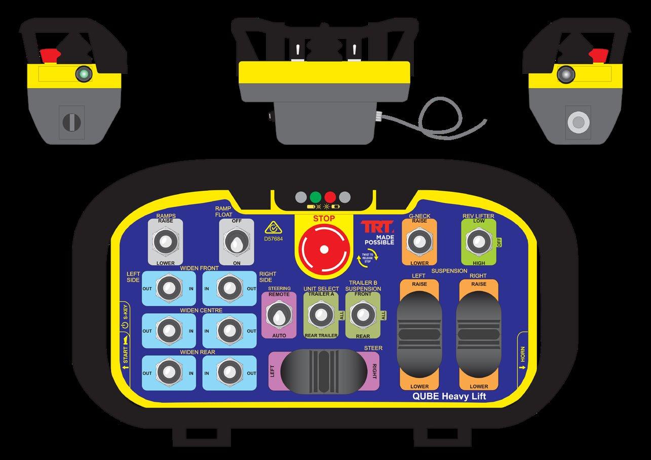
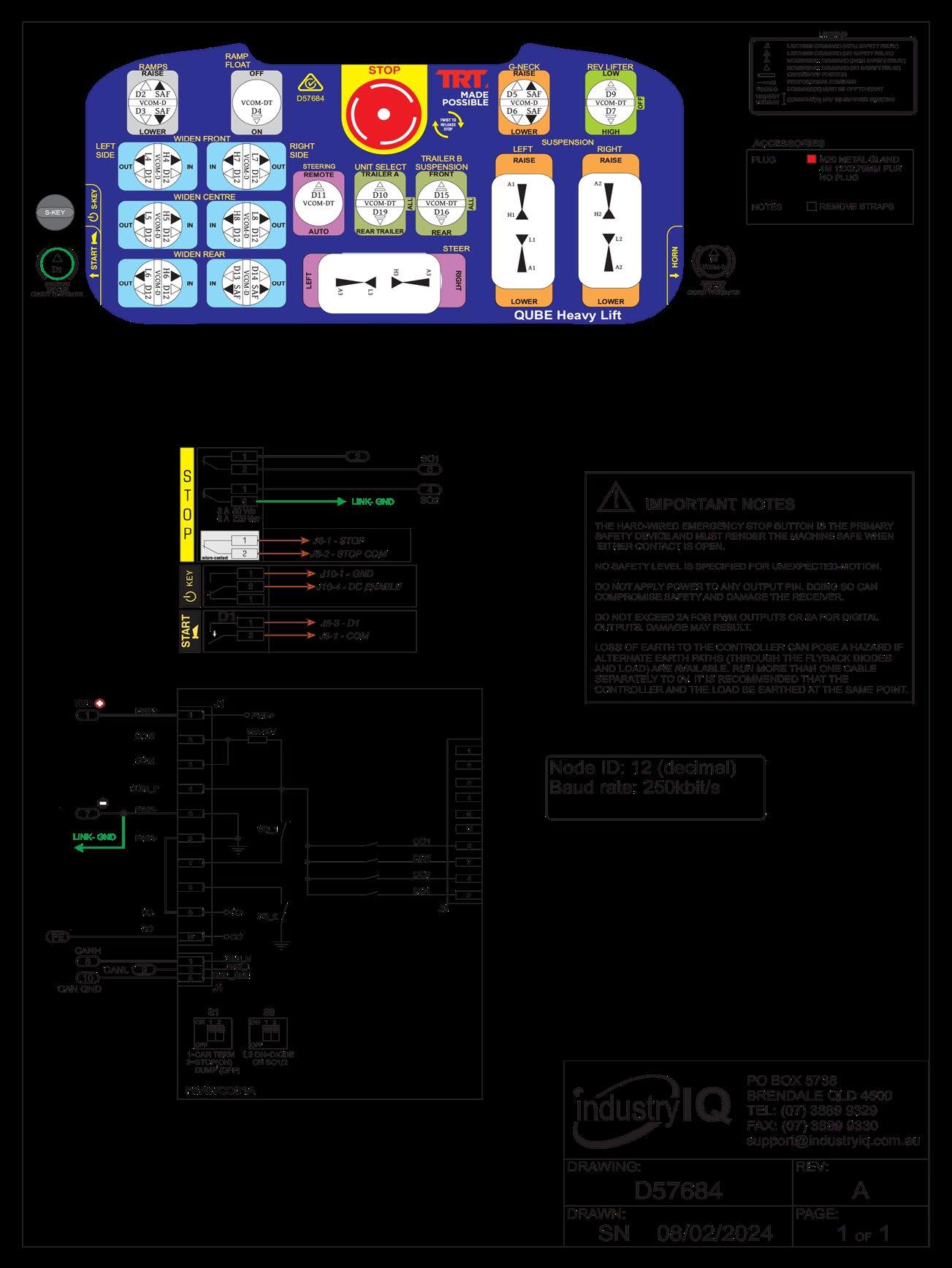
4.2.1 Radio Control
CONFIGURATION TRANSMITTERAUTO OFF AFTER MINS WITHOUT D2-D10 OR H/L(1-30 MINS)
WHEN SO1/2ARE CONFIGUREDAS STOP,THEYFORMTHE PRIMARYSAFETYELEMENT,AND WHEN OPEN MUST RENDER THE MACHINE SAFE.
WHEN SO1/2ARE CONFIGUREDAS SAFTHEYPROVIDE PROTECTIONAGAINSTUNEXPECTED MOTION FROM STANDSTILL, ANDARE OPEN WHEN NO MOTION COMMANDSAREACTIVE.THEY MUSTBLOCK POWER FLOWTOTHE MOTION DEVICES WHEN IN THATSTATE.
BOTHTHE HIGHAND LOW OUTPUTS MUSTBE USED IN ORDERTO ACHIEVE SAFETYCATEGORIES HIGHERTHAN CAT1.
DO NOTCONNECTAPOWER SOURCETOANYOUTPUTSAS POWER CAN FLOW BACKTHROUGHTHE SOLID-STATE OUTPUTS WITH UNEXPECTED RESULTS. USE DIODES OR RELAYSTO ISOLATEAS NECESSARY.
LOSS OF EARTHTOTHE RECEIVER CAN POSEAHAZARD IF ALTERNATE EARTH PATHS (THROUGHTHE FLYBACK DIODES AND LOAD)AREAVAILABLE. RUN SEPARATE CABLESTO 0VAND PE. ITIS RECOMMENDEDTHATTHE RECEIVERANDTHE LOAD BE EARTHEDATTHE SAME POINT. SEE INSTALLATION MANUAL.
NOTES ON IMPLEMENTATION Node ID = 10 (0Ah) Baud Rate = 250Kbit/s
4.2.3 Tethered Control
4.2.4 Tethered Control Schematic
4.3.1 5 - Line A Trailer Hydraulic Map


3 - Line Hydraulic Schematic
4.3.6 2 - Line Hydraulic Schematic
5.1 Power Pack
Battery
Battery for Starter Motor
Battery 12V 36Ah AGM (computer controll batteries)
Battery Charger 24V DC 20A (for computer controll batteries)
Coupling between Powerpack and Pump (Yanmar)
Engine Mount (Yanmar / Matalastik Eng mount)
Hydraulic Pump (Axial Piston - Variable Pressure)
Inline Pressure Filter Element (Complete Unit)
Inline Pressure Filter Element 10Um (Complete Unit)
Powerpack Isolator Mounts
Return Filter Element
Rev Lifter Ram(s)
Sight Glass (Level & Temperature)
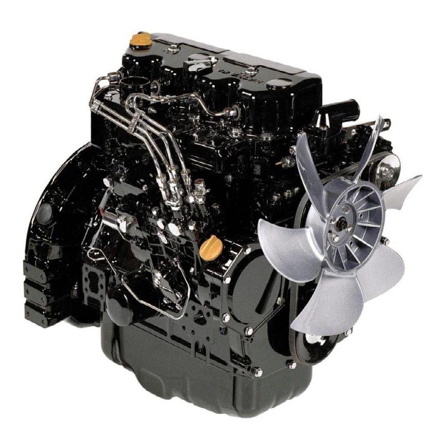
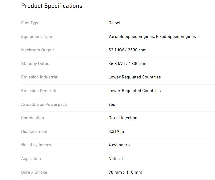
Yanmar 60hp 4cyl Diesel
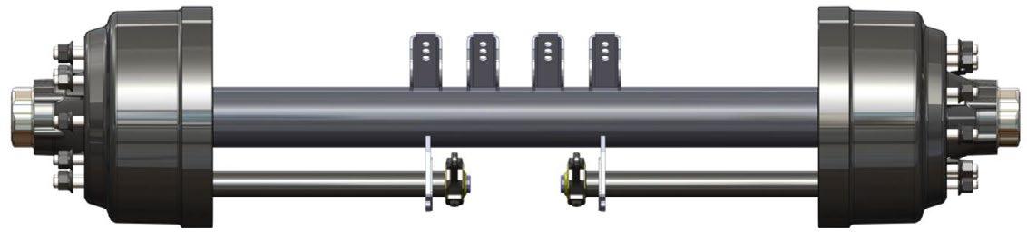
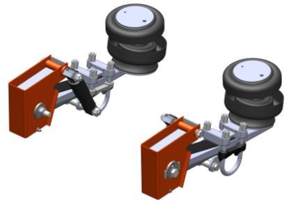
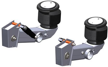
5.2 Suspension & Wheels
Axles
Bush - Sus Leg Pivot ACM Tribotex 102 x 85 x 80
Gasket - Platform Suspension Seal
Shim 304 SS 112 OD x 101 ID x 1.5mm Thick
Shim 304 SS 112 OD x 101 ID x 2.0mm Thick
Shim 304 SS 112 OD x 101 ID x 2.5mm Thick
Shim 304 SS 112 OD x 101 ID x 3.0mm Thick
NS70ZZ
CBNS70MF
AMREC36-12
ELBCDC2420
TDSAE4PPD
AD6050223
R940206717
RXR928030539
RXR928022275
IH80445R1 (2/mount)
TDESS1810E
SMCD85N1650BXC6B
AMLG6-10T
4TNV98
TM862660-786.3304
CM045-A3-P7D
TDCM045-A2-P22A
CM045-A1-P10-1.5
CM045-A1-P10-2
CM045-A1-P10-2.5
CM045-A1-P10-3
Spindle nut and Washer (KIT) AU 209325GWDT
Spacer Sleeve (Cone)
Spherical Tie Rod End (Weld-On)
CM045-A1-P6
TDGK35ES
Steering Kingpin Bearing Lower IKGE100SX
Steering Kingpin Bearing Upper IKGE120SX
Steering Kingpin Grease
Steering Ram Bush TRIBOTEX BUSH 70 x 60x 70
Castrol SBX2
TD20523BU1-0B
Steering Ram Bush TRIBOTEX* BUSH 70 x 60x 70
Steer Quadrant Bush 76 x 65 x 108
Tyre (215/75R17.5 135/133 16 Ply)
Thrust Bearing for Axle Pivot
Thrust Washer - Sus Leg ACM TRIBOTEX 132 x 90 x 8
Thrust Washer - Sus LegACM TRIBOTEX
Thrust Washer - ACM TRIBOTEX 100 x 65 x 3
Thrust Bearing for Bottom Suspension Arm
Thrust Bearing for Axle Pivot
Thrust Washer SS 134 x 90.3 x 1.5mm Susp. Leg
Thrust Washer SS 134 x 90.3 x 2mm Susp. Leg
Thrust Washer SS 134 x 90.3 x 2.5mm Susp. Leg
Thrust Washer - Bottom Susp. Arm 1.5mm SS
Tyre (215/75R17.5 135/133 16 Ply)
Vee Ring seal
Wheel (17.5” x 6” 10/225 26mm Stud) ALLOY
TD20523BU2-0B
TD096-A902-P7E
OG215/75R17.6
CM045-A15-P3C
TD CM045-A15-P3C
TD CM045-A15-P4C
TD096-A902-P13B
CM045-A3-P9C
CM045-A15-P3B
CM045-A15-P5-15
CM045-A15-P5-20
CM045-A15-P5-25
CM045-A3-P8-15
OG215/75R17.6
TDVA199N
OGAGR370
Accessory Valves - Gooseneck (see tag on valve)
Accessory Valves - Suspension (see tag on valve)
Accumulator 35L/ 360 bar AES
Accumulator 20L/ Gooseneck
Rexroth custom build
Rexroth custom build
AM3426010628
AM11093201125
Cartridge Valve - Counterbalance (Rexroth) GOOSENECK R940203324
Cartridge Valve - Counterbalance (Rexroth) SUSPENSION R940007048
Cartridge Valve - Relief HYRV1026A0N35
Cartridge Valve N/O Ramp Float HYSV10-24
Check Valve 3/8 Bolster FT260/6-38
Diverter Valve - 3 Port (Electric) 1/2 24vdc Watertable HY1607111
Hydraulic Pump (Axial Piston - Electronoic Variable Pressure)
RXR940206717
Handle for Suspension Locks AMDCV40-H
Manifold - Counterbalance (Steel) (Rexroth) SUSPENSION R940000716
Manifold Ramp Float HYHS1020P6N_B
Manifold for SVC10-22 Bolster HS1020P6_B
Pressure reducing cartridge Bolster PR1032AON08
Pressure reducing cartridge Manifold Bolster HS1030P6
Pressure sensor 0...280 Bar
RXR917A05562
Steering Valves (see tag on valve) Rexroth custom build
Solenoid valve NO 24vdc (one way check) AES
RXR940205272
Solenoid Coil for Ram / Widening Float (flying leads)Ramp Float 6352024
Solenoid cardridge valve Bolster SV 10-22
Valve Assy for Suspension Locks (incl. Handle) PLATFORM TDLVASS0812
24V Coil (flying leads) Bolster 6356024
5.3.1 Hydraulic Rams And Ram Parts/ Platform Specific
Clip-on Lock 125MM x 3.0” x 290mm
Gooseneck Ram 8.0 x 3.5” x 525mm (AU)
Ramps 4’x 2’ x 406MM
TDHYD53-001
TD299-5002
TDRR10050406Z
Steering Ram Position Sensor (220mm Stroke) Inside steer rams TDLA4421
Steering (Inc Tempersonic)
Widening - Front & Rear 100 x 50 x 670
Widening - Front & Rear 100 x 50 x 700
TDPL-22186H
TDPL-304-5001H
TDPL485-100-001-A
Air Toggle Switch SL216050
Check Valve 434/014/000/0
Control line filters
432/500/020/0
Drain Valve (Pull) WH12104
Pressure Limiting Va;lve 0.5bar Brake-by-wire kit
475/015/040/0
Pressure Protection Valve (65PSI) BX277147
Quick release valve MDKN32005
Quick release valve (WABCO) 973/500/000/0
Relay Valve for Service Brakes 2 Port (Sealco) SL110360
Relay Valve for Service Brakes 2 Port (Wabco) 4psi 973/011/006/0
Relay Valve for Spring Brakes 2 Port (Sealco) SL110701
Spring Brake T30/30 w/ Heavy Duty Housing AL3030SBGC-TSE
Slack Adjuster Auto 10spl 16mm Offset LH
Slack Adjuster Auto 10spl 16mm Offset RH
TM8180960
TM8180960
Wabco REV Towing Kit 971 002 150 0
Yard Release Valve SL17600B
12/24v solenoid NC Brake-by-wire kit
5.5
CDisplay Unit
Display Unit Mounts
Display Unit Plug
Controller BODAS RC28-14/30
Controller BODAS RC12-10/30
Controller BODAS RC10-10/31
Controller PLUG 154 PIN
WA4721271400
RXR917010009
RAM (manufacturer)
RXR917010017
RXR917A07683
RXR917A08181
RXR917A10287
RXR902603622
Gooseneck Rotary Encoder ELRM9000
Gooseneck Rotary Encoder (alt supplier - CAN Automotion Pty VIC Au)
WDGA-36J-10-1218-CO-AB-00
Elbow Connector (Encoder - 5 pin)
ELWACA057
EL22260128
Encoder Gear
Remote Control Transmitter / Receiver (Custom built)
Remote Control CAN Wired Handset (Custom built)
Cable - Devicenet DataThick (Purple PUR Sheath)
Cable - Devicenet DataThin (Purple PUR Sheath)
Cable - Olflex Truck Control Cable 2x6 3x1.5+(2x1.5)
5.5.1
ABS/EBS 7-Pin Plug w/ Screw Terminals
E18GB-3-A8-P2
TDDYNAMIC
TDDYNAMIC
EL2170344
EL2170345
EL7027093
HA8JA007644051
EPIC H-B 6 Box Mount Base (with cover) M25 thread CAN tethered remote LAPP-79015600
EPIC H-B 6 Hood M25 thread CAN tethered remote LAPP-19011000
EPIC H-BE 6 BF Female Insert CAN tethered remote LAPP-10401000
EPIC H-BE 6 Male Insert CAN tethered remote LAPP-10400000
Ignition Switch Yanmar
Spiral Cable (Suzie) 15 core 4Mtr
HA8KA007648041
Suzi Cable w/ 7-Pin Trailer Plug AM82524
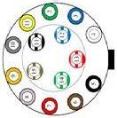
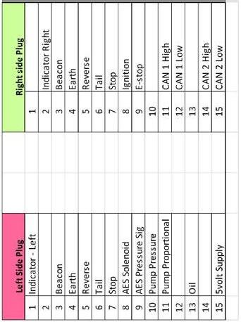
15-Pin Plug Round
15-Pin Socket Round
8-Pin HD30 Circular Connector (Motor plug)
5.6
Beacon Rotating 12/24V
Combination Light Rear LED (Indicator/ Stop/ Tail) w/ 3m Cable
HA8JA007241-021
HA8JB007242-011
ELACX2921
BCN01A
ELCRL280LED3M
Licence Light (LED) HA2559
Indicator Light (Amber) - Side HA2031
Marker Light (Red / Amber) HA2053
Marker Light (White) HA2054
Marker Light (Red) HA2307
Marker Light (Green) HA95963055
Reflector Rectangle 105mm x 55mm (Red) HA2926
Work Lamp LED HA1539LED
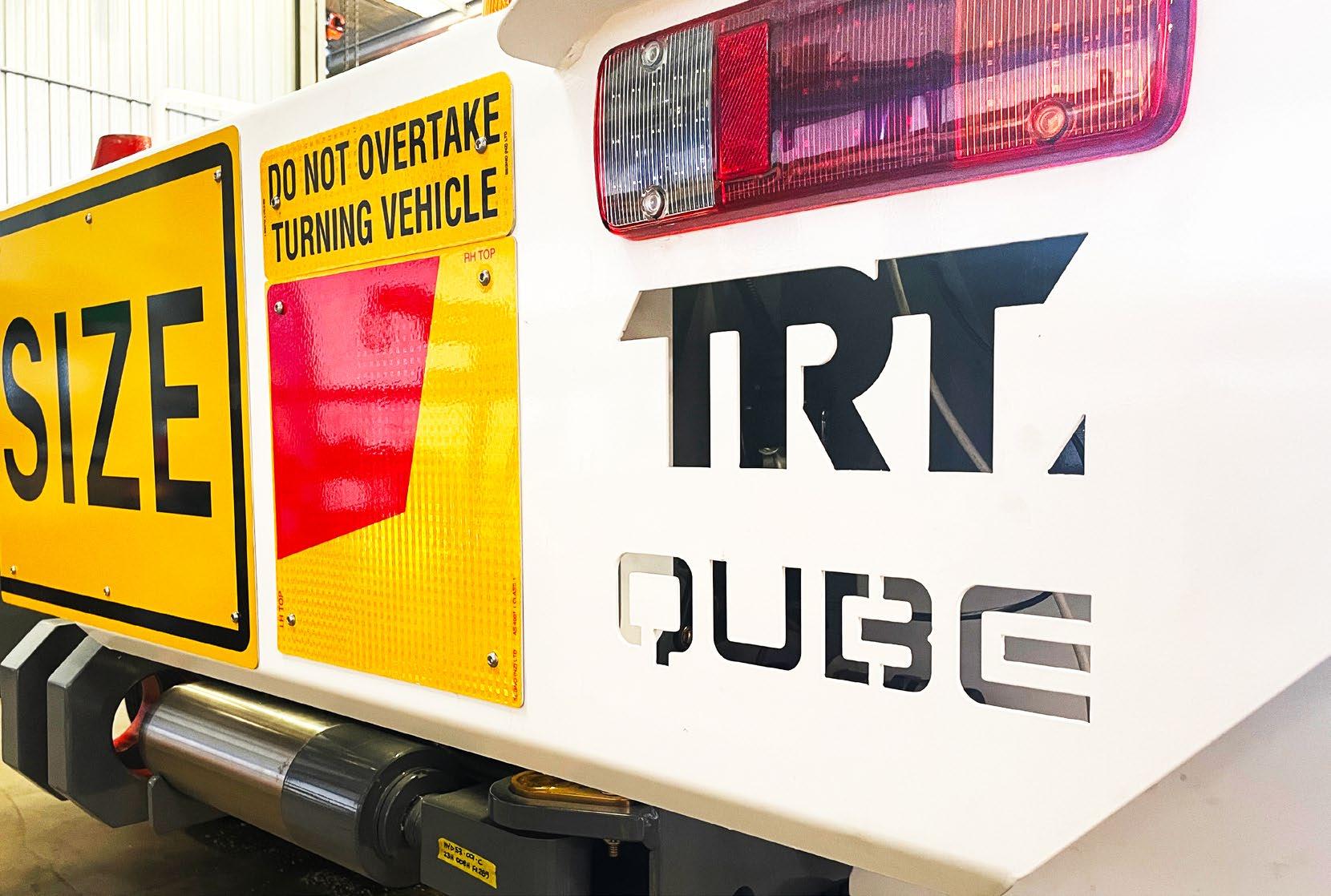
OVER SIZE 2 pce Class 2/ 450x600mm/ Al/SIGN
Rear marker with ‘DO NOT OVERTAKE’ (Au deligniator)
Rear marker with ‘DO NOT OVERTAKE’ (Au deligniator)
SPRING - Oversize Sign & Slack Adjuster
TRT Name Plate (Alloy) AUST
Trailer Decals
CIXT008/A
CIXT028/AL
CIXT028/AR
BW0539726030
TDTRTPAU
TRT Custom
Grease manifolds Alemlube
Kingpin - 3.5” Bolt up
JTKZ1016
Ramp Twitch AM685GHLB
Slew Ring for Platform Trailer E24VI097B
Support Leg Pin
Tool box T-handle
AMS9160
AM10502-CH510
6
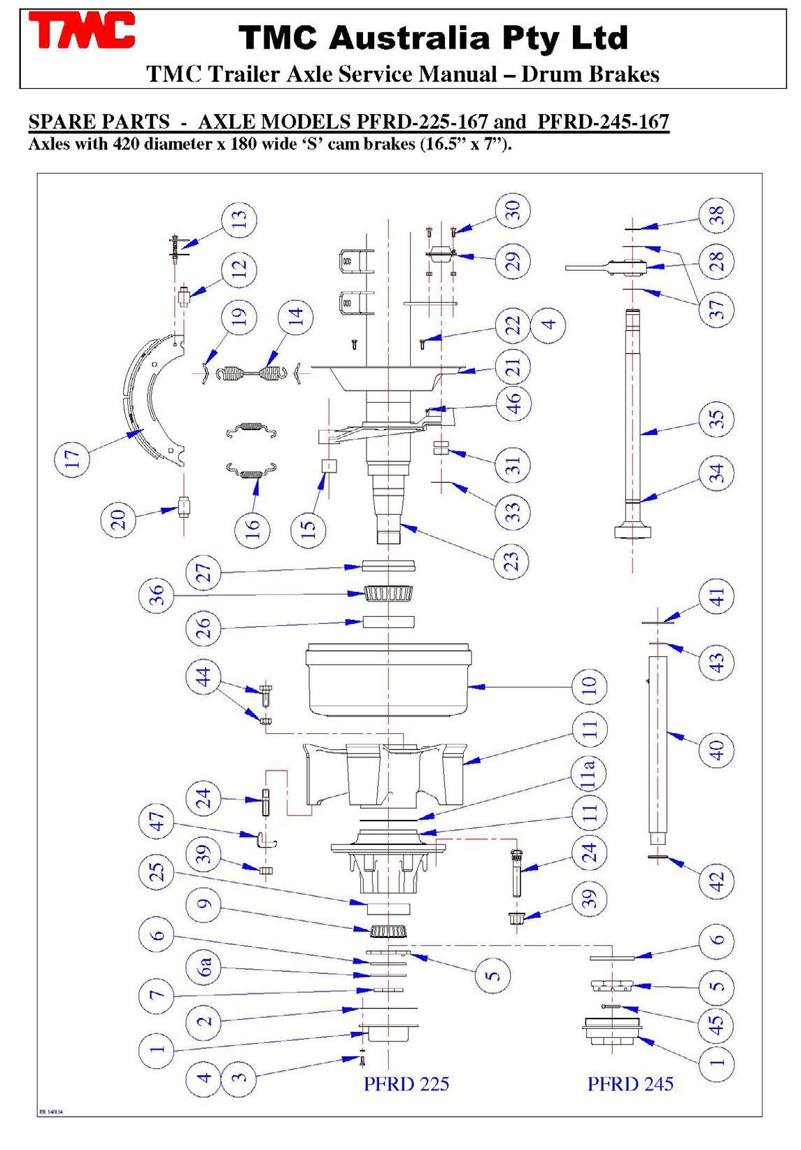
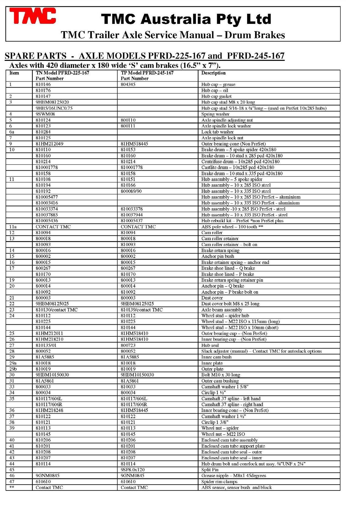
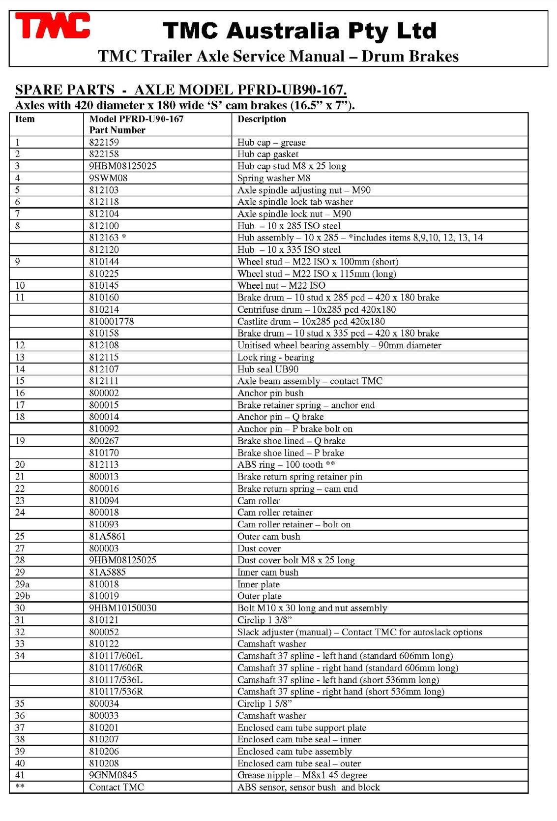
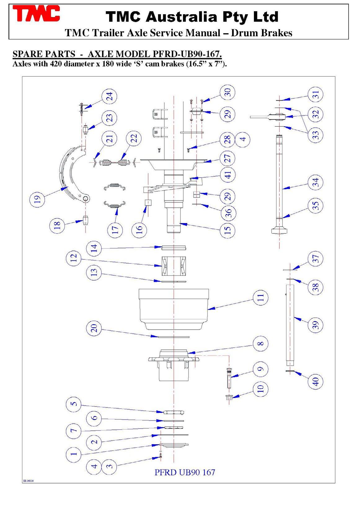
SPARE PARTS - AXLE MODELS PFRD-225-167 and PFRD-245-167
TN and TP Axles with 420 diameter x 180 wide ‘S’ cam brakes (16.5” x 7”).
5
TMC Axle and Suspension Spare Parts Listing
SPARE PARTS - AXLE MODEL PFRD-U82-136S.
Unitised Axles with 335 diameter x 210 wide ‘S’ cam brakes and Axles with 335 diameter x 160 wide ‘S’ cam brakes.
8
9
32 810061 Outer cam bushing
33 810105/616L& R Camshaft 10 spline – 616 long (L&R)
34 810122 Camshaft washer
35 810121 Camshaft circlip
36 810091 Enclosed cam tube assembly
37 810087 Enclosed cam tube support plate
38 810081 Enclosed cam tube seal – inner
39 810082 Enclosed cam tube seal – outer
40 9HNM10 Hex nut M10
41 9FWM10 Flat washer M10
42 SWM10 Spring washer M10
810169 ABS pole wheel – 100 tooth
810169/80 ABS pole wheel – 80 tooth
810300 ABS axle kit – 100 tooth
810300/80 ABS axle kit – 80 tooth
1
Brake chamber Type 16/16 universal 820133
Brake chamber Type 12/16 universal 820138
Brake chamber Type 14/16 universal 820139
Brake chamber Type 14/24 universal 820140
Brake chamber Type 20/16 universal 820149
Brake chamber Type 20/24 universal 22 820132
Brake chamber Type 16 universal 820134
Brake chamber Type 12 universal 820135
Brake chamber Type 24 universal
Brake chamber Type 20 universal 820136
Brake chamber Type 22 universal
(100 tooth optional) **
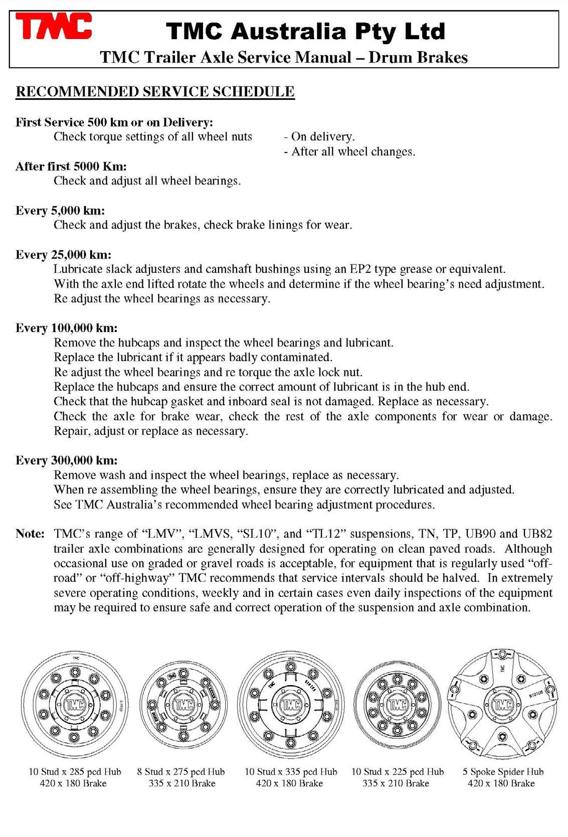
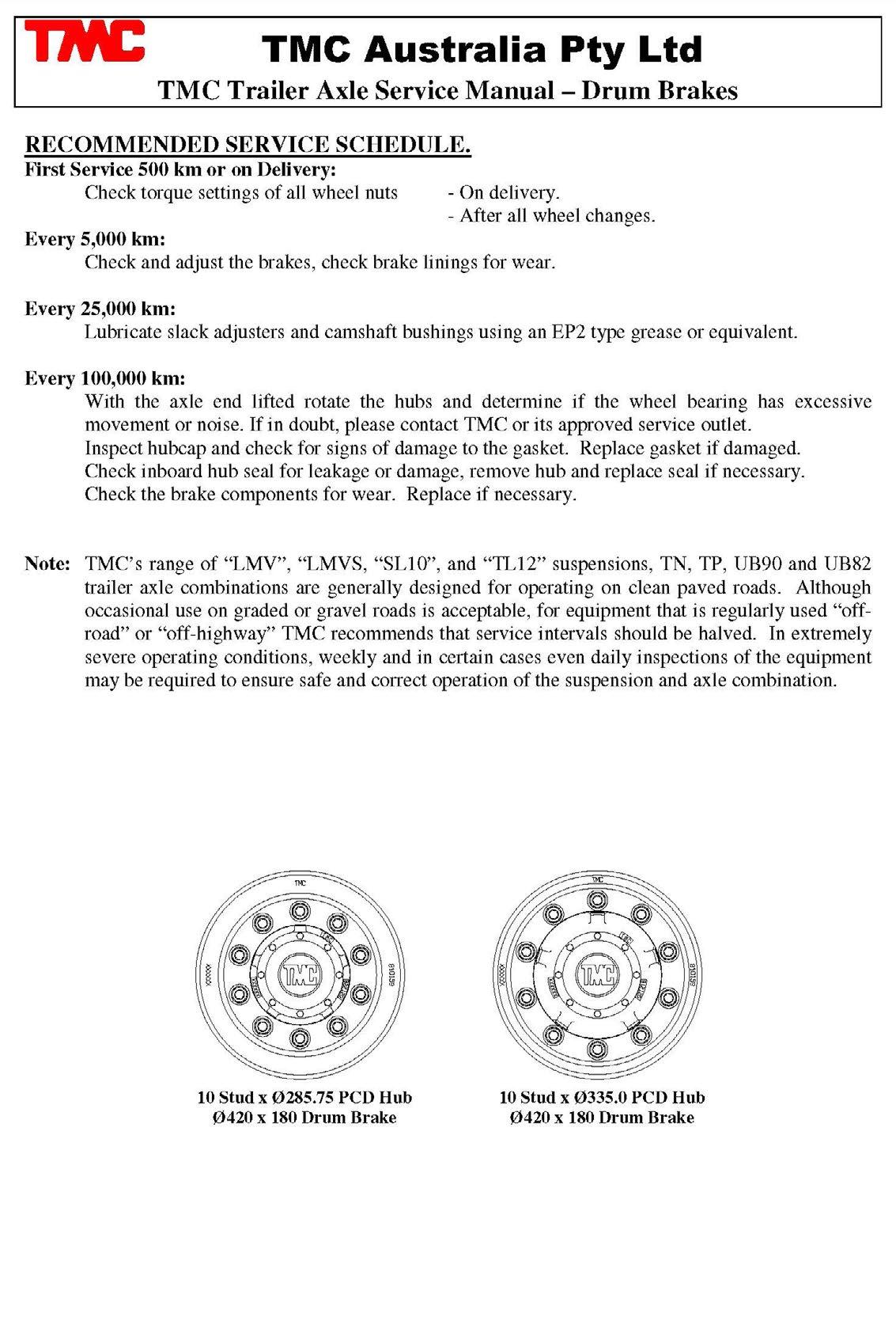
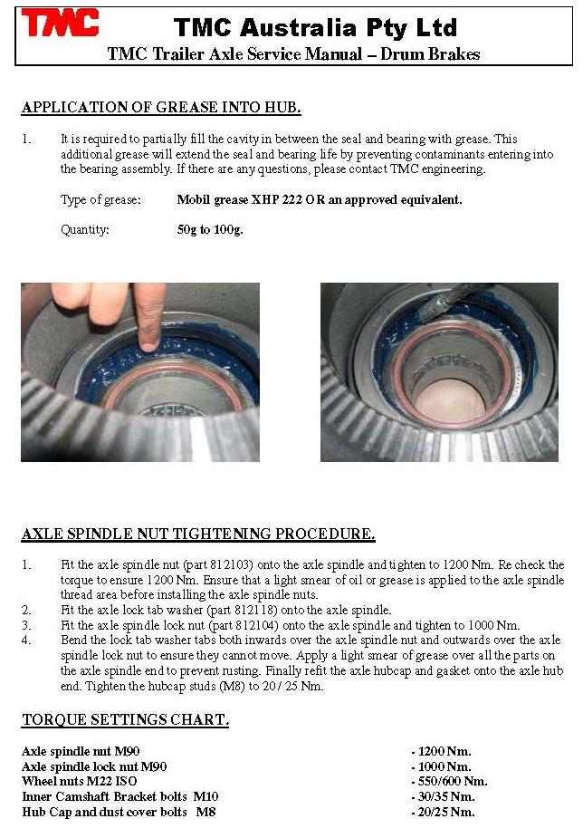
7. Drum Brake Service Manual
7. Drum Brake Service Manual
7. Drum Brake Service Manual
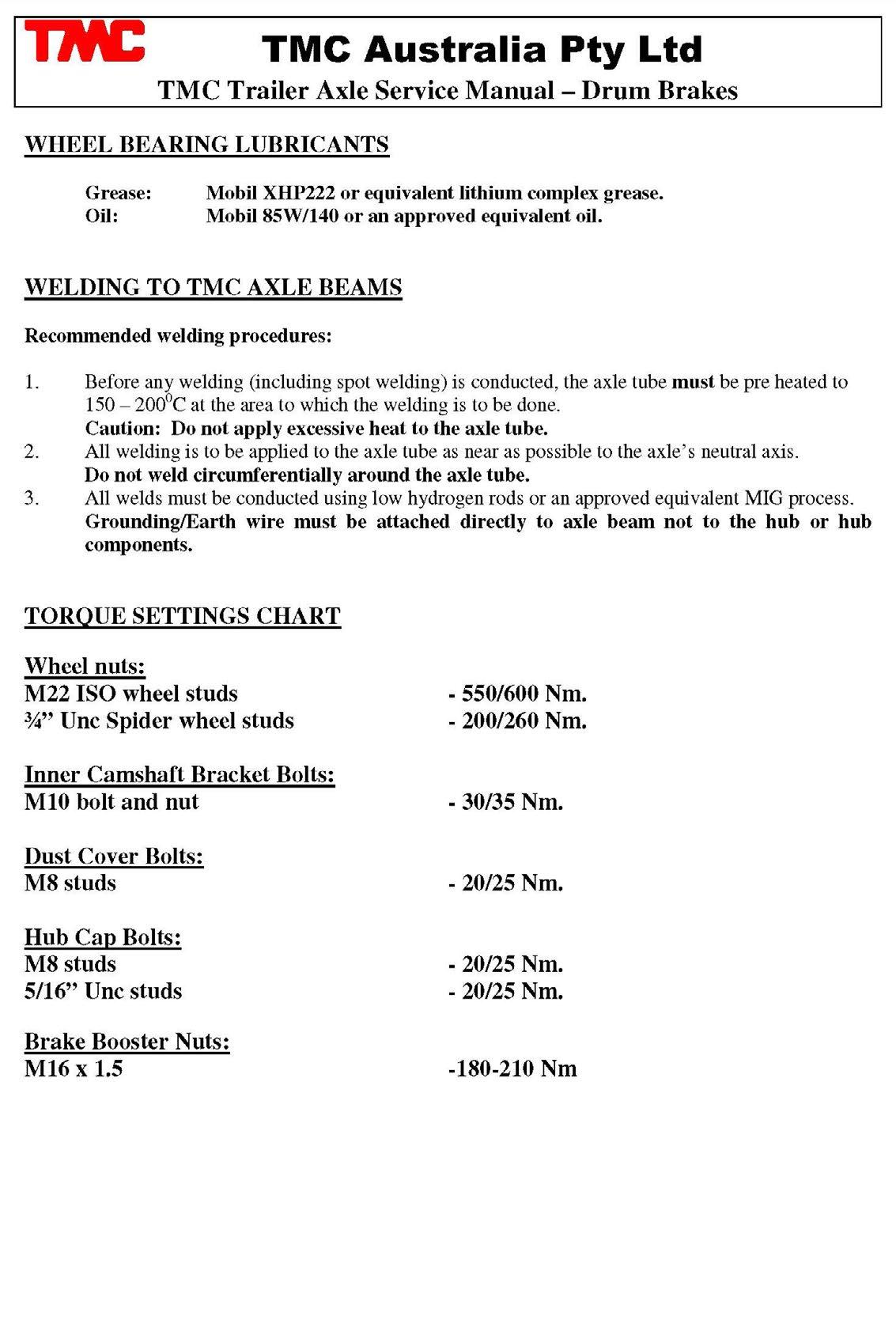
7. Drum Brake Service Manual
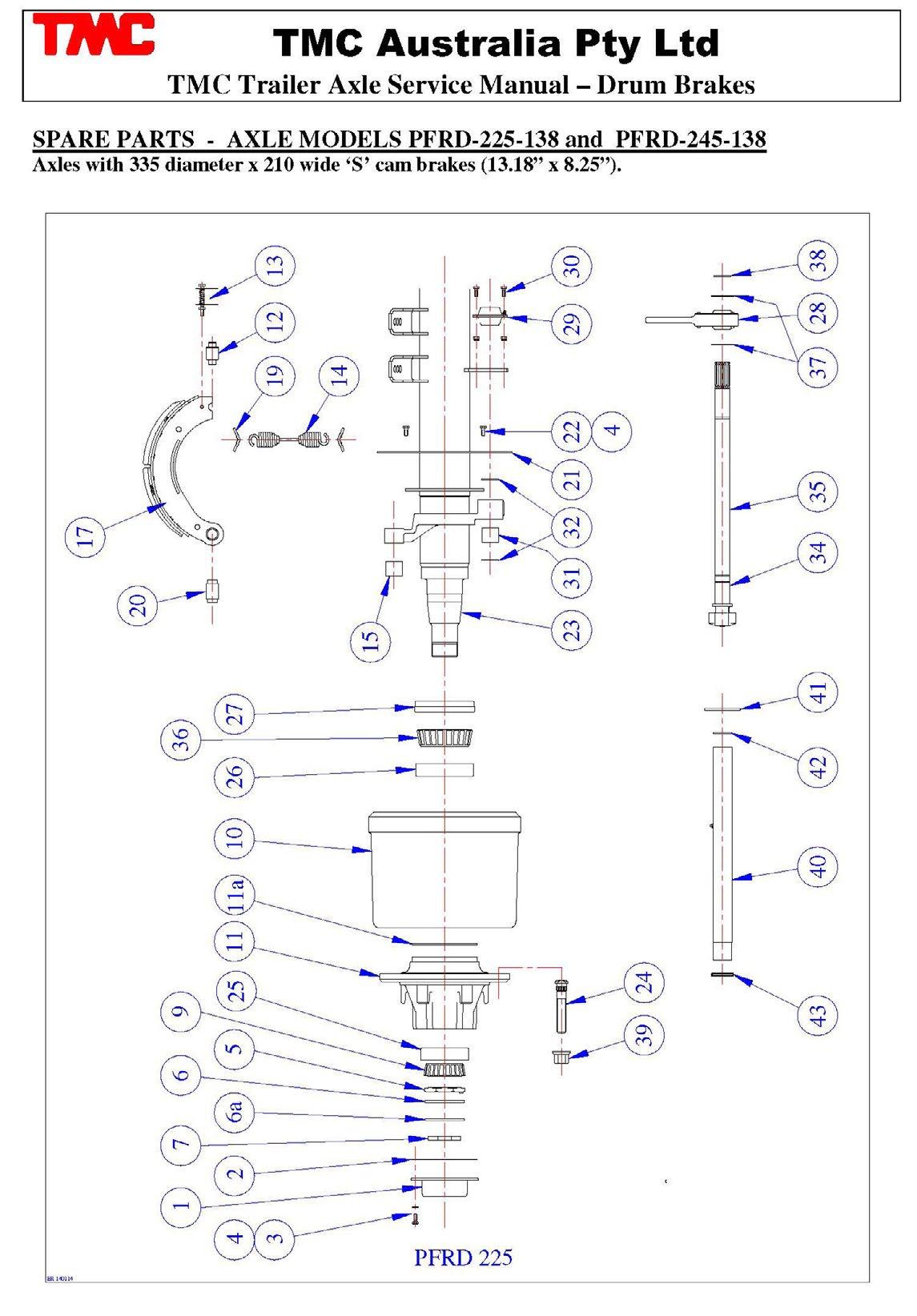
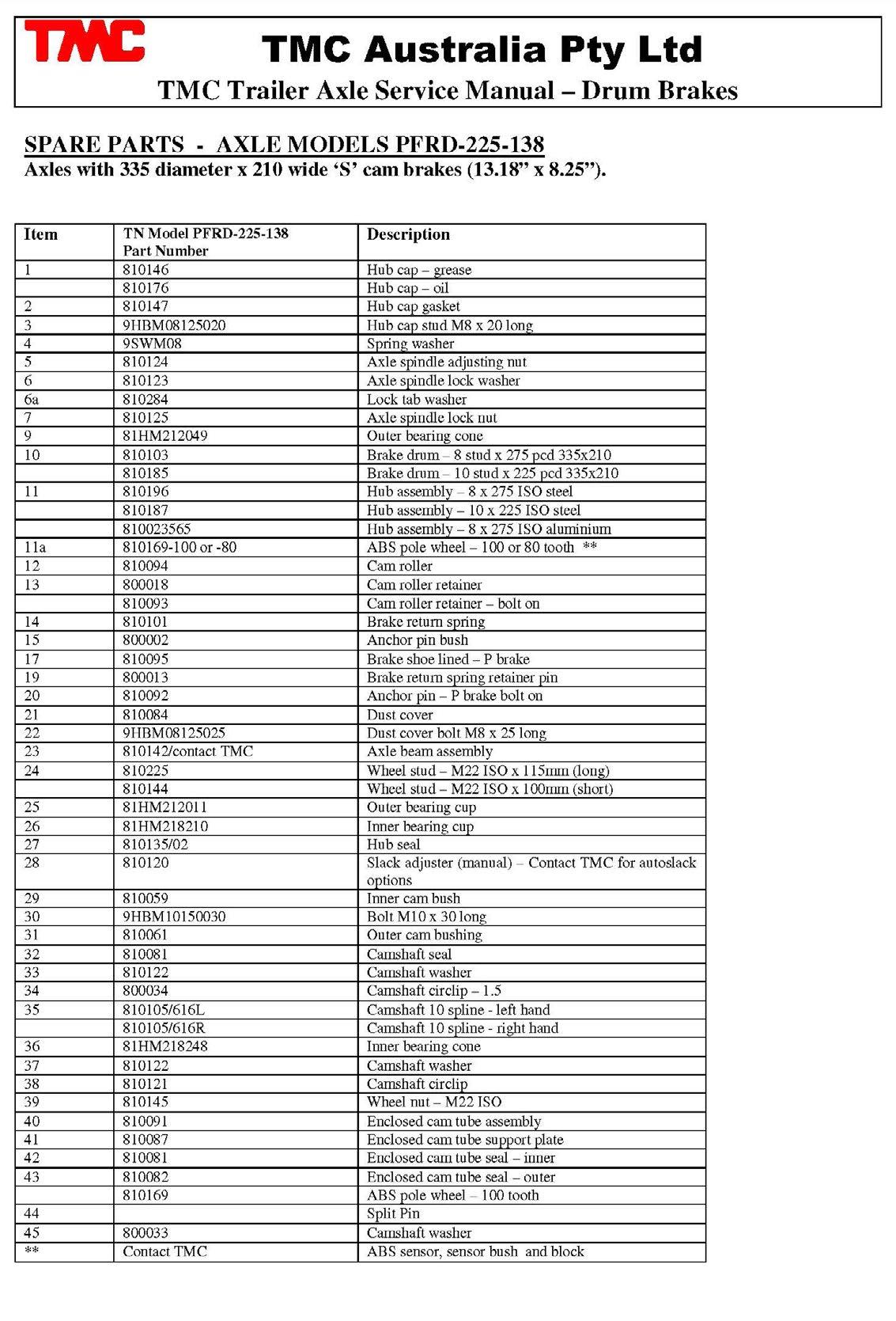
7. Drum Brake Service Manual
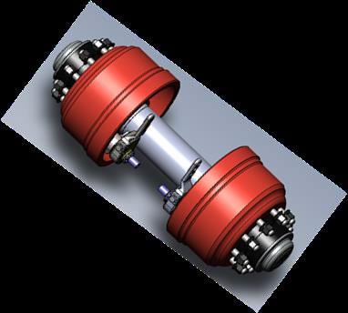
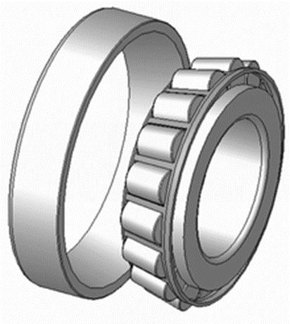
# Tapered roller bearings are essentially used in trailer axles because they can sustain large radial and axial (thrust) forces at moderate speeds. The conical geometry gives a larger contact patch and less wear than with other bearings such as spherical, plain, ball and even other roller bearings (needle, cylindrical etc).
# Tapered roller bearings are based on the fact that cones that meet at a point can roll over each other without slipping. In taper roller bearings, the line of action of the resultant load forms an angle or taper with the bearing axis. Taper roller bearings are therefore particularly suitable for carrying combined radial and axial loads. The steeper the cup angle, the greater the ability of the bearing to handle axial loads.
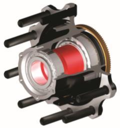
# Tapered roller bearings consist of four parts: inner and outer rings, tapered raceways and tapered rollers and cages. The inner ring and roller assembly is called the cone. The outer ring is called the cup.
# Bearing capacity and life are usually measured as:
• Static load capacity (Co) is the maximim static load (bearing not rotating)
• Dynamic load rating (C10) is that load which will cause 10% of sample of bearings to fail at or before 1 million revolutions. 90% of bearings would achieve at least 1 million revolutions at this load.
# Tapered roller bearing load life is usually measured in the number of revolutions which can then be translated to hours at a known speed.
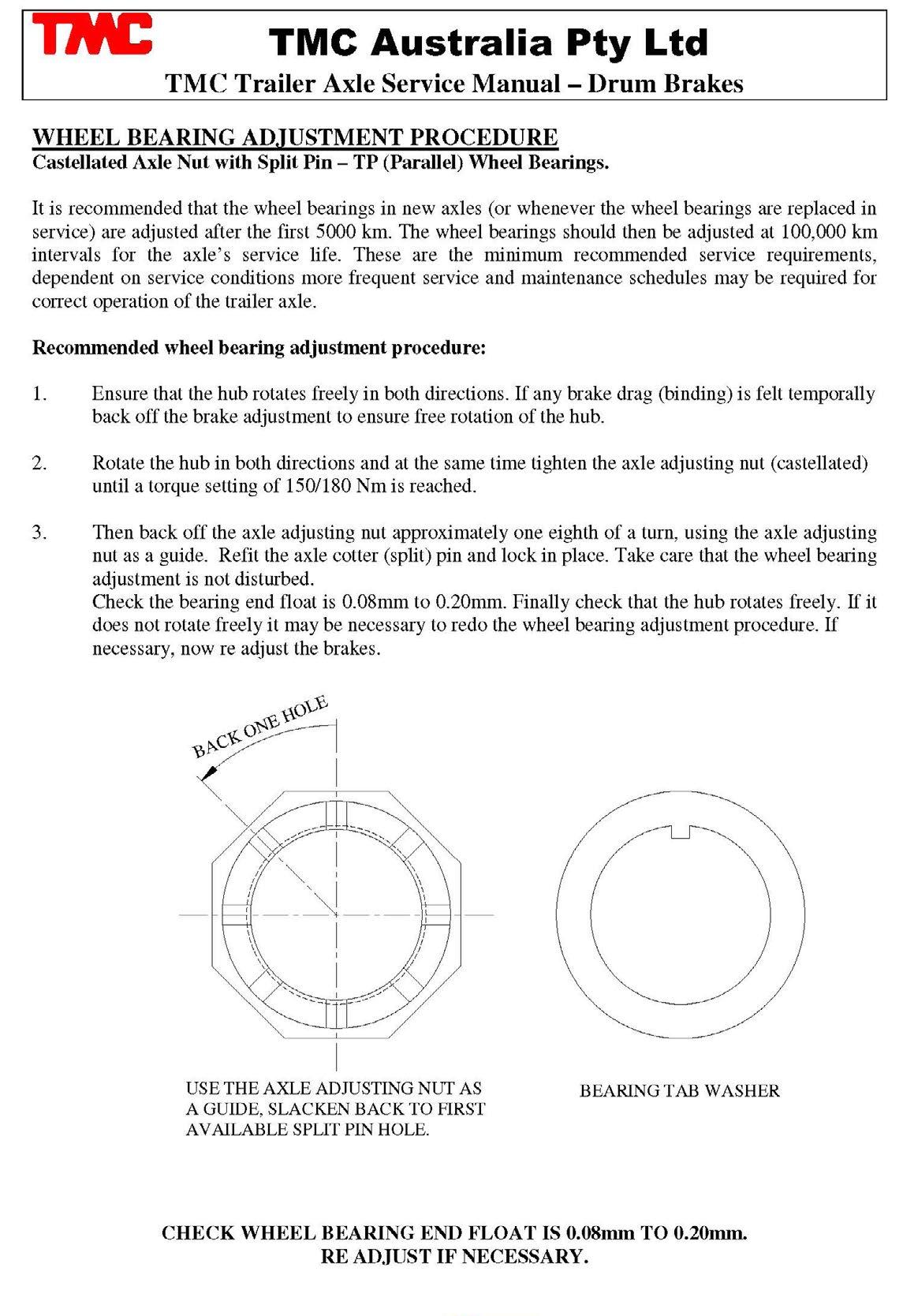
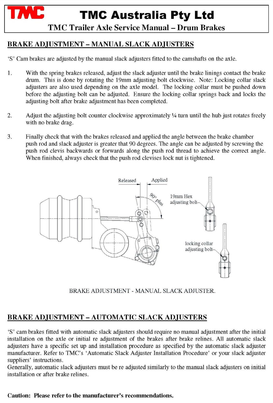
WHEEL BEARING ADJUSTMENT PROCEDURE – MANUAL ADJUSTMENT
Double Axle Lock Nuts and Lock Washer – TN Wheel Bearings, Suits drum and disc brake axles.
Recommended wheel bearing adjustment procedure:
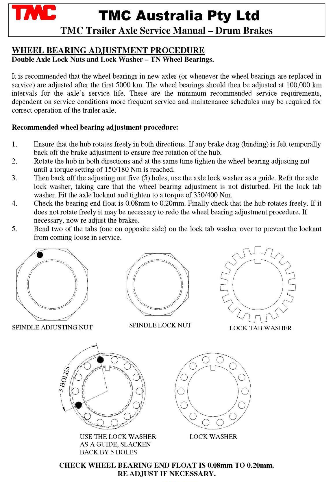
1. Ensure that the hub rotates freely in both directions. If any brake drag (binding) is felt temporally back off the brake adjustment to ensure free rotation of the hub.
2. Rotate the hub in both directions and at the same time tighten the wheel bearing adjusting nut until a torque setting of 150/180 Nm is reached.
3. Then back off the adjusting nut five (5) holes, use the axle lock washer as a guide. Refit the axle lock washer, taking care that the wheel bearing adjustment is not disturbed. Fit the lock tab washer. Fit the axle locknut and tighten to a torque of 350/400 Nm.
4. Check the bearing end float is 0.08mm to 0.20mm. Finally check that the hub rotates freely. If it does not rotate freely it may be necessary to redo the wheel bearing adjustment procedure. If necessary, now re adjust the brakes.
5. Bend two of the tabs (one on opposite side) on the lock tab washer over to prevent the locknut from coming loose in service.
SPINDLE ADJUSTING NUT
SPINDLE LOCK NUT
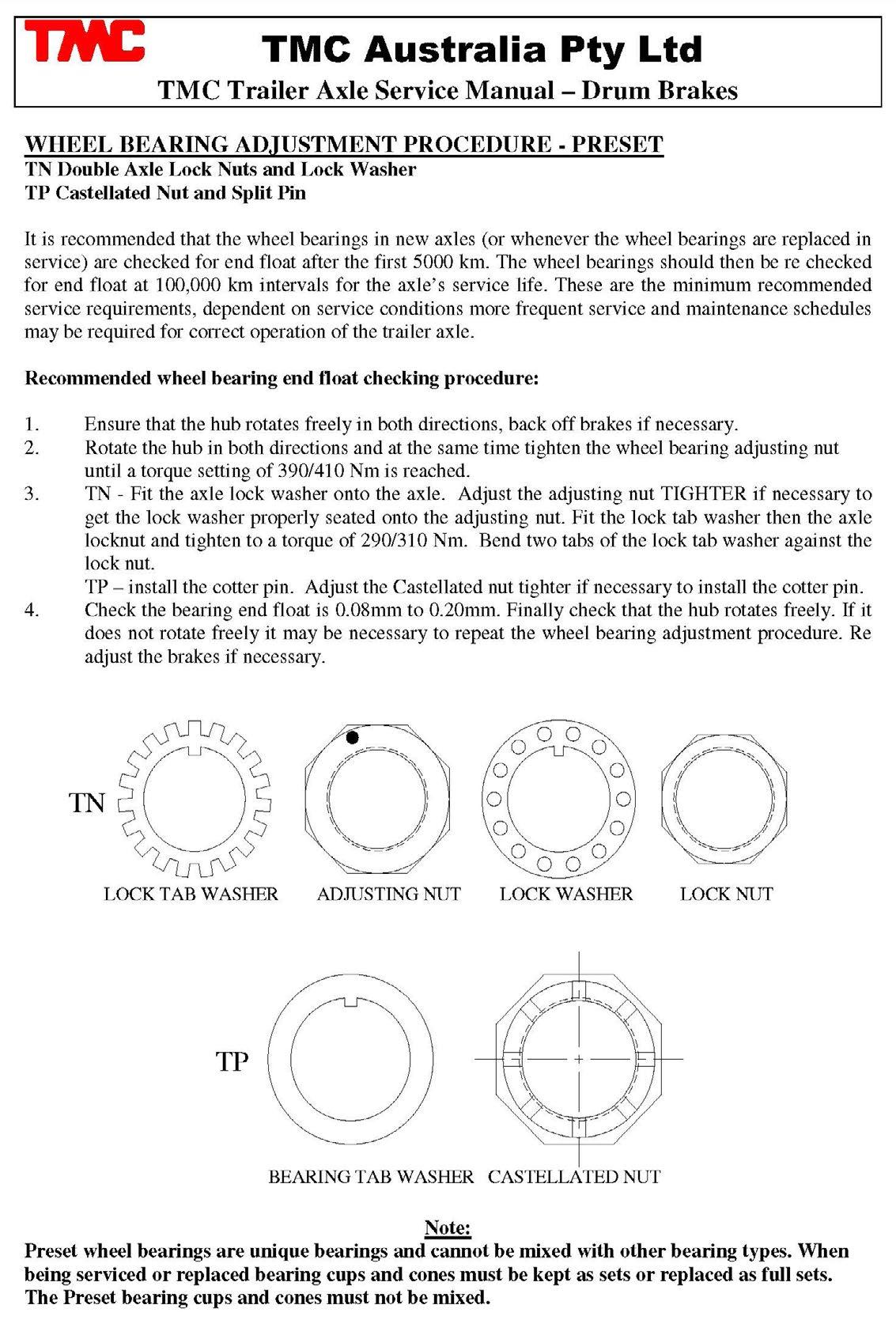
WHEEL BEARING ADJUSTMENT PROCEDURE – PRESET
TN Double Axle Lock Nuts and Lock Washer
Recommended wheel bearing end float checking procedure:
1. Ensure that the hub rotates freely in both directions, back off brakes if necessary.
2. Rotate the hub in both directions and at the same time tighten the wheel bearing adjusting nut until a torque setting of 390/410 Nm is reached.
3. TN - Fit the axle lock washer onto the axle. Adjust the adjusting nut TIGHTER if necessary to get the lock washer properly seated onto the adjusting nut. Fit the lock tab washer then the axle locknut and tighten to a torque of 290/310 Nm. Bend two tabs of the lock tab washer against the lock nut to prevent it coming loose in service.
4. Check the bearing end float is 0.08mm to 0.20mm. Finally check that the hub rotates freely. If it does not rotate freely it may be necessary to repeat the wheel bearing adjustment procedure. Re adjust the brakes if necessary.
Axle Spindle Adjusting Nut TN Part No. 810124
TN AXLE SPINDLE NUTS
Axle Spindle Locknut TN Part No. 810125
TN AXLE NUT SPANNERS
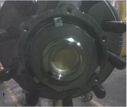
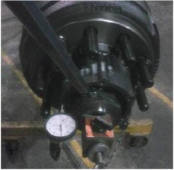
Recommended end float procedure (follow below or Timken method):
1. Ensure locknut has been torqued to 350/400 Nm.
2. Before bending the tabs on the lock tb washer, place magnetic base with dial indicator attached to spindle, and then line up dial indicator with the outer hub face so that it just makes contact with the hub.
3. Place pry bar in between the hub and lockwasher and apply a firm and even force to pry bar (up and down). The dial indicator reading (bearing end float) should be no less than 0.08mm and no more than 0.20mm. If the setting is correct, bend the tabs over. If setting is incorrect, readjust the adjusting nut and re -torque the locknut. Repeat process.
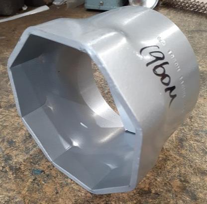
AXLE SPINDLE NUT TIGHTENING PROCEDURE – UB82
Double Axle Lock Nuts and Locktab Washer
Recommended wheel bearing end float checking procedure:
1. Apply a light film of anti -seize grease to the spindle bearing surface. Install hub ensuring seal is not damaged during installation. Apply a light film of anti -seize grease to the spindle thread and fit the axle spindle nut (part 812015). Tighten to 1000 Nm.
2. Fit the axle lock tab washer (part 812017) onto the axle spindle.
3. Fit the axle spindle lock nut (part 812016) onto the axle spindle and tighten to 800 Nm.
4. Bend the lock tab washer tabs both inwards over the axle spindle nut and outwards over the axle spindle lock nut to ensure they cannot move. Apply a light smear of grease over all the parts on the axle spindle end to prevent rusting. Finally refit the axle hubcap and gasket onto the axle hub end. Tighten the hubcap studs (M8) to 20 / 25 Nm.
UB82 AXLE SPINDLE NUTS
Axle Spindle Adjusting Nut UB82
Part No. 812015
Axle Spindle Locknut UB82
Part No. 812016
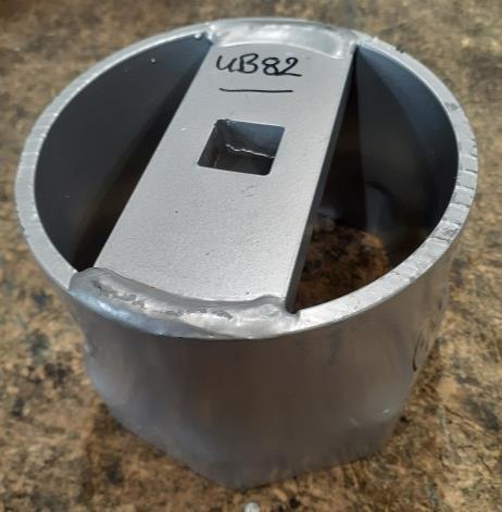
UB82 AXLE NUT SPANNER
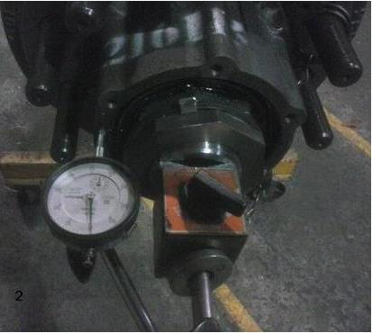
1. Clean and inspect the wheel bearings and seal bore each time the hub is removed or when contamination is evident. Replace all damaged bearings and seals as a unit if any of them is damaged.
2. Follow the lubrication and bearing service interval requirements.
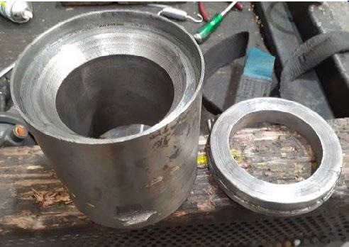
1. Separate the hub from the spindle and wheels.
2. Thoroughly clean and degrease the hub with a nonflammable solvent.
3. It is recommended that the hub be heated evenly throughout in an oven or in boiling water to approximately 100 dec C. See below for an alternative method.
4. Remove the hub from the oven or water and quickly press out the bearing cup. Take care to avoid damage to the bearing cup bore and shoulder. (Variations within tolerances of materials and oven temperatures may allow the bearing cup to drop in and out easily).
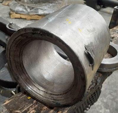
Alternate Procedure:
Use an electric welder to weld a large bead around the inside surface of the bearing cup.
Do not deposit weld spatter on to the hub. Let the assembly cool or quench in water. The weld will cause the cup to shrink enough to allow it to be easily removed.
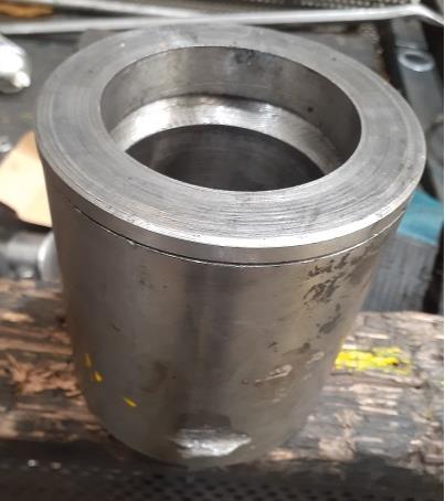
5. To replace the bearing cup, heat the hub evenly as in step 3 above.
6. Remove the hub from the oven or water quickly and press in the new bearing cup. Be sure the cup is properly aligned and fully seated. Take care to avoid damage to the bearing bore and shoulder. Be sure both cups are fully seated before installing the hub. If the cup is being pressed into an unheated hub, additional installation force will be required. To reduce the installation force the cup can be put in a freezer for an hour Prior to installation.
1. Thoroughly clean and dry the hub in the bearings cups and hub void area. The cleaning operation should be conducted using a clean solvent damped cloth and then wiped clean with a dry cloth. Inspect for damage to the bearing bore and indication of movement of the bearing cone during service. Replace the hub if there is any evidence of damage.
2. Warm hub in either an oven or by hot water to approximately 100 Deg C.
3. Quickly press in a new bearing cup, using a suitable pressing disc. Make sure the cup is correctly aligned and fully seated in the hub. Take care to avoid damage to the bearing bore and shoulder.
4. If the bearing cup is pressed into an unheated hub, additional Pressure will be required. This can be reduced by placing the cup in the freezer for approximately 1 hour prior to installation.
5. Grease the bearing cones, hub and spindle surface in accordance with the specification. Mobil XHP222 (NLGI Grade 2) or equivalent lithium complex grease is to be used.
6. Fit the pre-greased inner bearing cone inside the hub and cup. Fit the hub seal and drive the seal home against the hub shoulder using the a hammer and seal installation tool. Ensure the seal is free and can move
7. Lift the hub/drum assembly and slide the assembly onto the spindle. Ensure the inside of the drum is clean.
8. Using the inner bearing seating tool, drive the inner bearing cone home against the spindle shoulder. Ensure the bearing is hard up against the shoulder.
9. Fit the pre-greased outer bearing cone using a seating tool, fit the spindle adjuster nut, lock washer, lock-tab washer and spindle adjusting nut.
10. Adjust the wheel bearings in accordance with the specification, and then replace the hub cap with the new gasket.
11. New wheel bearing seals and hubcap gaskets need to be installed during a bearing installation. Seals should be replaced every time the hubs are removed from the spindle. Refer to the seal installation guideline.
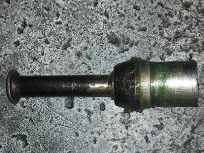
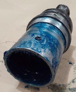
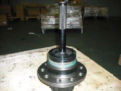
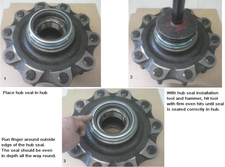
UB82 SPINDLE MOUNTED HUB SEAL PRESS TOOL 9. Bearing Adjustment and Seal Installation Guidelines
UB82 BEARING and HUB SEAL INSTALLATION
9. Bearing Adjustment and Seal Installation Guidelines
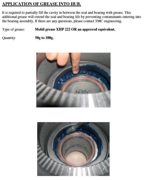
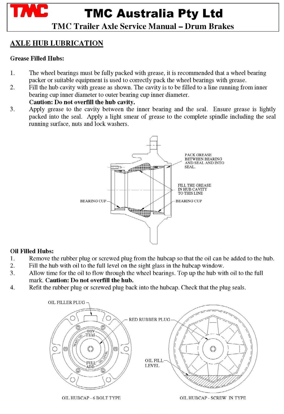
GREASE IN BEARINGS:
Grease should be applied evenly in the bearings so that the bearings are packed. Traces of grease should appear from the surface of the cone. For proper lubrication, the grease must be packed between the rollers and cage of the bearing cones. A mechanical grease packer will improve the procedure of packing the bearings. Store pre -greased bearings covered and in a clean environment for protection from dust and dirt.
GREASE IN HUBCAPS:
There should be atleast 0.5 to 1 cm high of grease inserted in the grease hubcap.
GREASE IN HUBS:
Grease should be applied evenly around the hub cavity or “hub well” and filled to a line running from inner bearing cup diameter to outer bearing cup diameter. Always ensure that this “packing grease” is distributed evenly around the “hub well”, to ensure satisfactory lubrication of the bearings
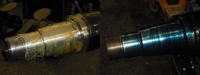
GREASE ON SPINDLE
SURFACE:
Grease should be lightly smeared over the complete surface of the spindles.
9. Bearing Adjustment and Seal Installation Guidelines
The recommended grease to be used in our axles is a Lithium Complex type grease NLGI grade 2. Mobil HP 222 is the main Brand, but other brands such as Castrol APXT, Timken AP, or Castrol EPX can all be used.
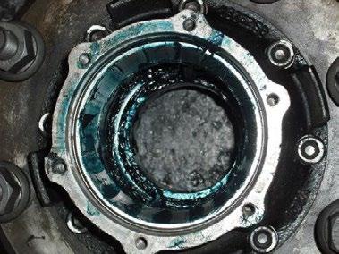
Grease other the specified type above is not recommended. Grease with traces of Molybdenum Disulphide is not recommended. Molybdenum Disulphide is an extreme pressure additive and is readily used in applications to prevent seizure of components. Moly grease causes the grease to go black and is not recommended for rolling element bearings.
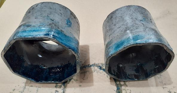
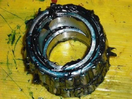
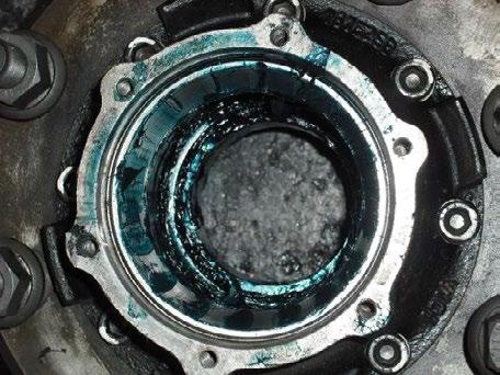
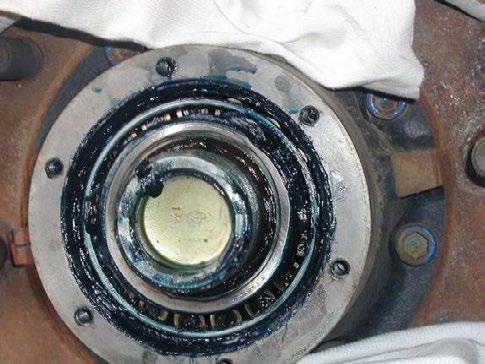
If discoloured bearing grease is observed in the hub, this is often shown by a grease with a thin, dark and muddy complexion. This could indicate that the bearings were exposed to an ingress of water and dirt or other contaminant.
Generally, discoloured bearing grease indicates one of:
(i) Exposure to high levels of heat.
(ii) Improper/Insufficient lubrication.
(iii) Improper bearing adjustment, i.e. excessive preload/end play.
(iv) Excessive wear of the rollers, rings cages etc, causing overheating.
(v) Excessive ingress of water and dirt.
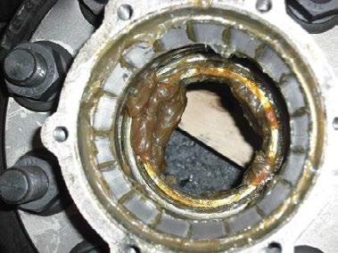
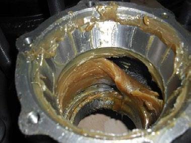
The signs for excessive heat are:
(i) The grease has a decrease in viscosity, solidifies or becomes oily and tacky. It has a tendency to evaporate with increasing temperature. There is a loss in the ability to support the load.
(ii) The grease becomes oily, and has a burnt aroma.
(iii) Overloading the axle, will cause excessive heat to be generated and can cause premature bearing failure.
After the wheel bearing adjustment is carried out, the hub should then spin freely. The bearings would then be considered to be functional.
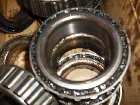
A premature bearing failure could be due to:
(i) Ingress of water and dirt or other contaminant. Grease becomes discoloured.
(ii) Excessive loads causing brinelling (severe impact to the bearing).
(iii) Manufacturing/Installation defects such as the fit of the bearing cups and cones (tolerances are out of specification etc).
(iv) Improper preload, i.e. due to bearing spacer or axle nut torque out of specification.
Too much end play could result in symptoms of noise, and erratic steering.
(v) Overheating issues.
Look for any scuffing marks, ID/OD wear etc. A premature hub seal failure could be due to:
(i) Inadequate installation, i.e was the seal cocked, or not seated correctly, was the seal installed backwards etc?.
ii) Was any lubrication present on the seal lip on the axle journal?.
(iii) Excessive heat. If the seal looks and feels rough and dry, this could be an indicator of excessive heat.
The recommended axle spindle wear limits, including inner (I) and outer (O) bearing journals and spindle end to bearing shoulder measurement (S). Axle types affected are TN,TP, UB90 and UB82.

Note:
The recommended spindle wear limits are denoted by dimensions shown with *
The recommended Brake Drum Wear Limits used in TMC 335x160, 335x210 and 420x180 drum braked axles.
DRUM SIZE
335x210 (17.5”/19.5”)
PFRD-225-138
PFRD-245-138
PFRD-U82-138
PFRD-225-136
PFRD-U82-136
(20”/22.5”)
PFRD-225-167
PFRD-245-167
PFRD-U90-167
TRT can supply service kits for the ESS Power packs
AMKITESS250 (250 hr service kit)
Fuel Filter
Oil Filter
AMKITESS500 (500 hr service kit)
Fuel Filter
Oil Filter
VEE Belt
Air Filter (inner)
Air Filter (outer)
Pressure Filter
Return Filter
Check Replace Contact your Yanmar service agent
Air Intake
Clean or replace, may need more frequent service in dusty conditions
Cylinder head Intake and Exhaust valve
Electrical
Check Battery water Before operation
Check Charging indicator At start-up
Injectors Inspect spray pattern
Check level Before operation
Drain and refill
Engine Oil
Replace Oil Filter
Check for leaks
Exhaust
Before and after operation
Check Rain flap if fitted
Fuel Fuel level Before operation
Check water trap for water, Drain if present
Replace fuel filter
Check level
Coolant
Inspect hoses
Inspect Radiator mounts
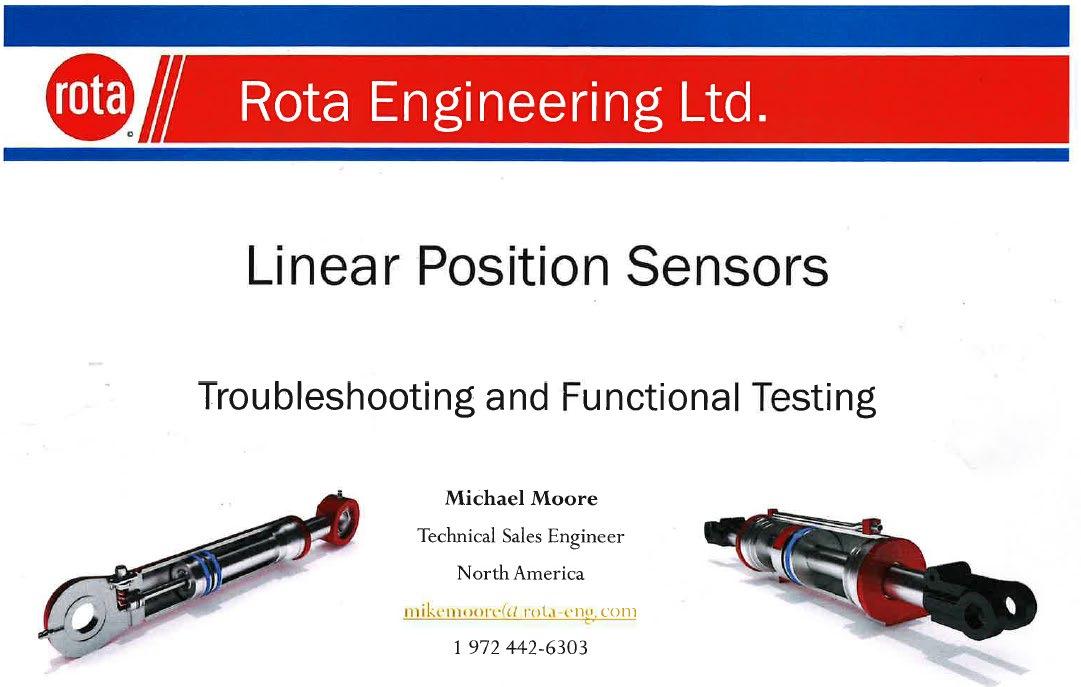

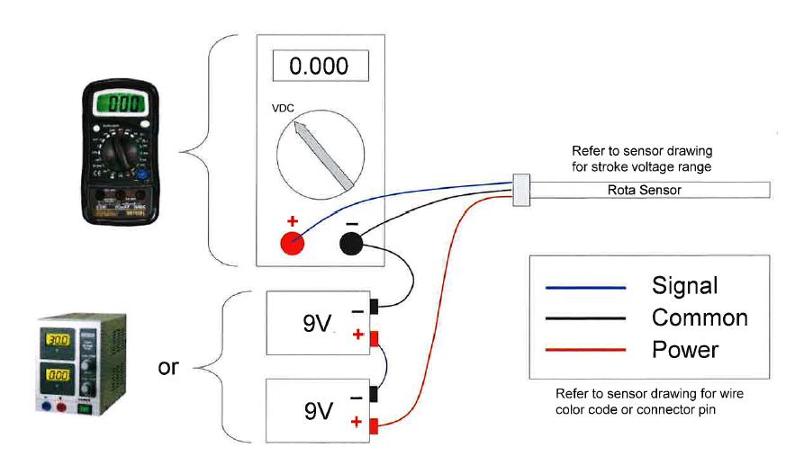
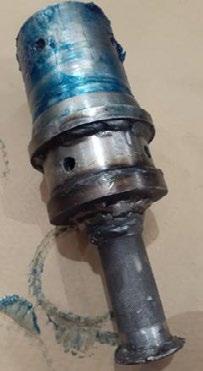
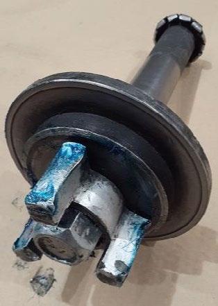
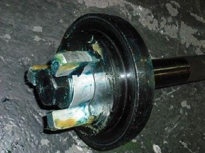
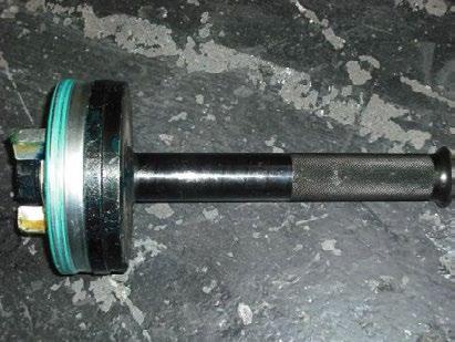
Ram Head-nut

Transducer

Plug and
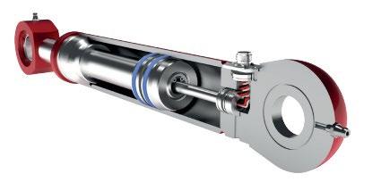
Spear and Piston

Transducer Magnet
Transducer Rod
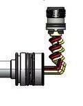
Transducer O-ring and Locating ring (Grub-screw slot)

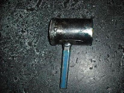
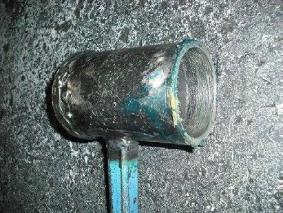
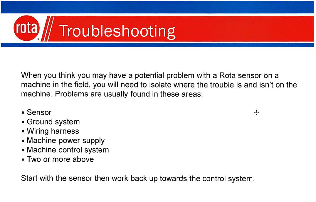
1. Remove the ram from the trailer, Clean it and mount it in a vice, or similar, for dismantling
2. Unwind the head-nut and carefully remove the ram spear and piston from the ram Barrel. Take care to keep the Spear etc in line with the barrel as it is being removed as the transducer slides inside the ram spear.
3. Remove the 2 screws that retain the Plug to the barrel
4. Locate and remove the small grub screw that retains the Transducer in the ram
5. Pull the transducer out of the end of the barrel. Take care to thread the wires and plug through the cavity as the transducer is withdrawn from the ram
1. Inspect the ram barrel and spear to ensure it is ok to be re-used
2. Unsure the O-ring on the replacement transducer is lubricated
3. Run a draw-string through the cavity and tie it lightly to the plug.
4. As the transducer is slid into the barrel, draw the plug and wiring through the cavity (Do NOT damage the plug or wires during this process)
5. Push the transducer ‘home’ onto the seal cavity, and refit the grub-screw to hold it in place. Check the transducer is located properly and held in place
6. When the plug is all the way through the cavity, and in the correct position, secure it with its mount plate and screws.
7. Reassemble the ram by carefully sliding the piston and spear over the Transducer as it is inserted into the barrel. Tighten the Head nut
8. Test the ram for function and seal leaks before refitting
9. Test the transducer output is correct and stable as the ram is being tested.
Customer:
Gooseneck - UP / DOWN
Suspension Left - UP / DOWN
Suspension Right - UP / DOWN
Revs LOW / OFF / HIGH
Widening Controls
Ramps - UP / DOWN
Ramp Float - OFF / ON
Remote(s) Only
Remote(s) Only
Remote(s) Only
Remote(s) Only
Remote(s) Only
Remote(s) Only
Remote(s) Only
Date:
Engine start / Stop Switch
Engine Revs LOW / OFF/ HIGH Switch
Gooseneck UP / DOWN Paddle
Suspension Left - UP / DOWN Paddle
Suspension Right - UP / DOWN Paddle
Ramps - UP / DOWN Switch
Ramp Float Switch
Steer Manual Auto Switch
Steer Direction Paddle
Horn Button
Screen inputs
Diagnostics
Auto steer
Crab Auto
Manual steer
Rear Axle Straight
Steer pivot point
Speed cut-out for steer functions
Valves accessible on wheels
Adjustable using Bodas if customer requires a change
Options go grey and cant be selected
Revs Powerpack to 1800 or 2400rpm
Decals Correct Decal replacements available on request
OVERSIZE sign
Steer Alignment
Grease manifolds
Requires technician to re-set if required
Grease Main Leg pin
Protects the ramps and rams when loading the trailer
TRAILER CONFIGURATIONS
Splitting and joining the trailer
Light bars
Push bar
Dolly hook-up and hydraulic supply
Importance of clean couplers
Importance of clean couplers electrical Plugs
DO NOT HOT PLUG!
Screen set-up
120ohm resistors
TRAINER (Name and Signature)
Care in moving screen between trucks
Fitted in CAN looms
Acknowledging I/we have run the trainee through the function checks stated above.
TRAINEE (Name and Signature)
Be careful if servicing electrical plugs
DATE
Acknowledging I/we have been run through the function checks stated above.