WHEEL NUTS MUST BE RE-TORQUED AFTER 100KM OF A WHEEL BEING REMOVED
AUSTRALIAN TRAILERS MUST HAVE THEIR WHEELS RETORQUED BEFORE LEAVING THE PORT
WARNING
TRT HYDRAULIC SUSPENSION
When lowering or raising the trailer, the hydraulics must be powered up or down
This will ensure that both sides of the suspension cylinders are full of oil.
Damage to these cylinders may occur if this instruction is not adhered to.
Lowering the trailer without the power pack running will cause air / vacuum to be drawn into the spear side of the cylinder.
Failure to operate the trailer in the correct manner will void warranty.
DO NOT Power-wash
Electrical Enclosures or Brake Valves
WARNING
WELDING ON THIS TRAILER
Major components of this trailer are made from GRADE 80 High Tensile steel, PREHEATING BEFORE WELDING is essential to avoid post welding cracking.
Please contact TRT for welding procedures and consumable specifications before welding.
TRT
Brennan Rietema
Nick Marsh
+64 7 8494839
+64 2198 4744
+64 2194 7174
Failure to contact TRT to gain the proper weld procedure could cause additional failures and may result in the warranty being voided.
BEFORE OPERATING TRAILER:
King Pin must be amply greased with E.P. grease with MoS2 or graphite additive.
Sufficient greasing of King Pin and fifth wheel coupling is most important for the lifetime of both components.
OPERATION
PRE-USE INSTRUCTIONS
On each occasion prior to using the transporter the following procedures must be carried out, to ensure the safe operation of the transporter and the safety of the personnel involved:
• Ensure that the maintenance schedule is up to date
• Walk around the trailer to check for obvious faults such as:
- Tyres are all correctly inflated including the spares.
- Wheel nuts and studs are tight with none missing
- No air leaks from hoses, tanks, valves or couplings
- No hydraulic leaks from rams, hoses or valves.
- No structural cracks to chassis.
- Wheel alignment is correct
• Check that the trailer kingpin is the correct size and is fully engaged with the 5th wheel and that all the hydraulic, electric and air couplings are fitted correctly.
• Test that brakes and lights are fully operational.
• Ensure that load security devices, which will be required, are carried. This means dunnage and matting. These are to be stowed securely to prevent movement while travelling.
• Check that you have the required permits to cover the intended load.
• Check that the suspension is set to the correct height and that enough of the axles are fully compensating for the load that is to be carried.
• Check that the route has adequate ground clearance to that which the trailer has available. This is particularly important over railway lines and off-road situations.
• Allow for road traction, which is significantly reduced, in wet or unsealed conditions.
• Be aware of weather conditions as these can affect the load. Rain and fog can reduce traction, increase stopping times and reduce visibility. High winds will affect the stability of the load. Hot conditions will increase tyre pressures and heat build-up within the axles.
TRAILER SERVICES
A services plate is located on the front of the Trailer. It has…
7-pin
EBS
FEMALE Air Coupling
MALE Air Coupling
Trailer lighting socket
Supply and return for the EBS unit
Brake service ait (Blue line)
Emergency air (Red line)
The spare tyres are mounted to the headboard and are held in place using a J-hook and a Large profiled wingnut (‘Spinner’).
The J-hook is threaded far enough to hold either 1, or 2, tyres at a time
The tyre rack can be removed from the trailer by removing the 2 retention pins. These are held in place with a spring clip behind the trailer front panel.
Both work lights mounted to the headboard have quick connectors that need to be separated prior to the headboard being removed from the trailer.
TOP DECK RAMPS
This trailer has 2 ramps stowed under the top deck. These are used to access the top deck with small machines/vehicles that do not exceed 4.5 tonnes.
1. Lower the access plates by releasing the spring bolts that latch them closed.
2. Release the spring bolt that retains the ramp in place in its guide
3. Slide the ramps out of their retainers
4. locate the studs fitted in the top of the ramps mount plate into the holes along the rear lip of the top deck. Position the ramps to allow safe loading of the top Deck.
Ramp cover plate and spring bolt
LANDING LEGS
This trailer has been fitted with RAZOR electric landing actuators. The landing legs are JOST.
The Controller is wired to a battery case, the battery is kept charged by a 9-30volt connection to the tractor unit through pins 3 (Earth) and 5 (Auxiliary +) OR 7 (Tail lights) This means that the landing legs can be operated electrically without a tractor unit attached to it.
The electric control unit also still has use of the landing legs gear set. By pulling the controller out, or pushing it in, (as you would do with a manual crank handle) the gear ratio controlling the leg speed is changed.
IN = High speed – Low torque OUT = Low speed – High torque
To operate the Razor electric landing legs.
1. Turn the unit ON by pressing and holding the RED button for 3 seconds
2. Arrow UP = Legs up
3. Arrow Down = Legs down
The leg controller has buttons to turn controls ON and OFF and move legs UP and DOWN.
Operation:
• Push the red Button to power on the controller
• Push either the Green (Legs Down) or the Blue (legs UP) button.
If the effort to raise or lower the trailer is too great the controller will turn OFF. If this happens pull the Razor drive unit OUT to change into low speed – High torque mode.
TOOL BOXES
2 lockable boxes on the front of the decks.
CHASSIS COVERS
This trailer is fitted with a central chain tray, behind the gooseneck.
1 lockable toolbox each side between axles 2 and 3
Oversize sign holder
The rear 2 cover sheets on the trailer’s spine are removable for maintenance and inspection purposes The centre countersunk bolt in the centre can be removed and a lifting eye installed for safety and ease of lifting the cover sheets.
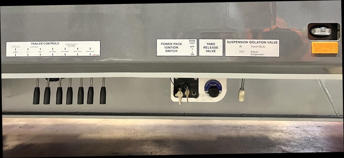
TRAILER CONTROL STATION
Left
Widen Front Right Widen Rear Right Widen Front Left Widen Rear Left
The trailer control station is on the Right side of the trailer and ahead of the first axle. From this area you can start the powerpack and operate all of the trailers hydraulic functions.
If an axle set has to be raised and locked in the raised position, the axle isolation valves will need to be accessed. The control levers for these valves are behind stainless on the RIGHT side of the trailer
HYDRAULIC DELIVERY AND FILTRATION:
Power-pack:
A motor (5hp Yanmar Diesel) is located under the left-side deck near the front. This pumps the oil from the oil reservoir to the trailer controls on the Right-side of the trailer.
It is recommended that the engine oil be replaced every 6 months (more often if it is used in dusty conditions).
Please refer to engine operator’s manual supplied with the motor or contact Yanmar service agent for operational and service issues.
Note: For extensive Powerpack Servicing/maintenance it is recommended that the hydraulic pressure/return lines be disconnected and the full powerpack + start battery tray be unbolted and lowered.
RETURN FILTER
A Return filter is located in the top of the oil reservoir. Change at 6 monthly intervals. Inspect filter on removal for metallic or plastic particles that would indicate seal failure.
Oil Tank Filler Breather
NOTE: When checking oil level in the tank the trailer should be fully LOWERED Decks closed, and ramps lowered.
PRESSURE FILTER
A Pressure filter is located in the spine, forward of the control station. Change at 6 monthly intervals.
Pressure Filter
CAUTI0N
When lowering the trailer, the Hydraulic power source (Power pack) must be operating. This will ensure that both sides of the suspension cylinders are full of oil. Damage to these cylinders may occur if this instruction is not adhered to.
Lowering the trailer without the Hydraulic power source running will cause air / vacuum to be drawn into the spear side of the cylinder.
Failure to operate the trailer in the correct manner will void warranty.
Please read DECAL information before operation
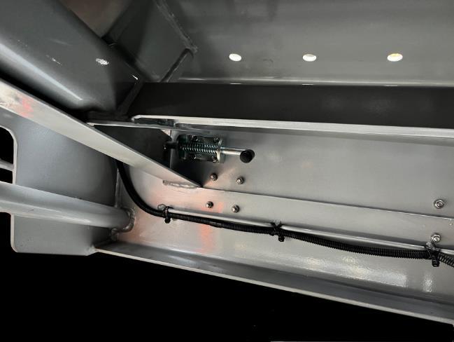
SUSPENSION ISOLATION VALVE
A suspension isolation valve is located near the suspension control valve. The purpose of this valve is to isolate the load from the control valve. When the lever is in the travel mode (IN) the valve is closed and suspension load rests on the isolation valve.
Pulling the lever OUT opens the valve and allows the suspension to be adjusted.
When the lever is in the travel mode the valve is closed and suspension load rests on the isolation valve.
• The hydraulic suspension in these trailers is robust and operated correctly will give many years of trouble-free use.
• The suspension is designed to travel about the mid-stroke of the ram to give maximum compensation for terrain conditions. Ride height at 946-950mm.
• The suspension has double acting rams and can therefore be driven up or down depending on the required ride height. Set this to suit the terrain allowing for axle movement.
• All axles have the capability of being locked in position. It is important to note that when in the lock position the axle will not compensate for the load being shared across the trailer. Do not lock axles off when there is a possibility that the axle rating will be exceeded.
To raise and lock an axle off the ground:
1. Lower the Trailer: Bring the trailer down to its lowest position.
2. Set the Valves: Locate and set the valves on the right-hand side of the trailer to the LOCK position for the axle that you want to lift.
3. Raise the Trailer: Increase the height of the trailer until it reaches the desired ride height.
4. Check Stability: Ensure that the axles remain in the raised position and that the trailer is stable.
5. Avoid Unlocking: Do not unlock the valves while the axles are raised, as this could cause the axles to drop suddenly, potentially damaging components and creating instability.
Lock valves – Pull a handle OUT to lock a suspension line
• Do not travel with the suspension fully raised or fully lowered. The suspension is designed to compensate over irregularities in the terrain, so if the rams cannot move they will become overstressed if the whole load is carried on a limited nmber of rams.
• Be aware that when raising and lowering the suspension that there is slight rearward and forward movement respectively of the trailer.
• There is limited ability to raise or lower only 1 side of the trailer at a time. This is due to the nature of the suspension. Operate BOTH suspension levers at the same time when raising or lowering a load then do minor corrections to get trailer level
• Never raise or lower the trailer while resting on landing legs as these may collapse.
CAUTION
WHEN WORKING UNDER THE TRAILER ALL SUSPENSION LOCK VALVES SHOULD BE IN THE LOCKED POSITION ALONG WITH THE FRONT SUSPENSION ISOLATION VALVE.
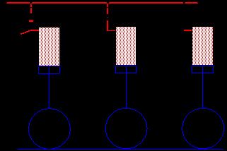
SUSPENSION RIDEHEIGHT EXAMPLES:
RIDE-HEIGHT TOO LOW
The oil cannot transfer from the compressing cylinder in axle 1 as it travels over the hump. This is due to no travel being left in the axle 1 cylinder The whole weight of the trailer would be carried on axle 1
In the example shown the load is taken on the first axle, with no load sharing on the others. The trailer could ‘break its back’
Direction of travel
In the example shown the load is again taken on the first axle, this time there is no volume in the other rams for the oil to pump into, with no load sharing on the others. The trailer could ‘break its back’
Direction of travel
In the example shown the load is taken by the whole trailer. The 1st and 2nd axles have compressed and pumped some oil into axles 3 and 4
AXLE LIFTED
In the example below the 3rd axle will walk over the hump, but the 4th axle may ride up on the hump and end up carrying a lot of the trailers load
When an axle is lifted, extra care must be taken to ensure it does not end up carrying the weight of the trailer.
of travel
Direction of travel
Direction
DECK WIDENING OPERATION
• Controls for widening are at the control station on the Right Side of the trailer
• Ensure that the ramps are in the raised position before operating deck widening.
• When opening or closing the trailer width, ensure the decks are operated in a manner that keeps them parallel
HYDRAULIC RAMP OPERATION
Ramp Operation:
• Ensure that the trailer is on a flat even surface and there is at least 10 metres of clear space behind the trailer for loading when using the ramps. The surface behind the transporter should not be lower than the transporter wheels or you may damage the ramps
• Place the trailer brakes in the parked position and start the powerpack
• Lower the trailer suspension down onto the axle stops using the suspension control levers
CAUTION:
Inspect the ground under the chassis rails to avoid point loading at the axle cut-outs. If the chassis is hung up on a rock or mount the trailer will need moving to flatter ground. Point loading the chassis at the axle cutouts can cause deformation of the lower flange.
• Release ramp restraints by activating the air switches (1 per ramp)
This will cause the ramp schain cam to release the pressure on the ramp chain
• Go to the ramp control valve and operate lever in the down position to power the ramps down. When they close to the ground, PUSH the ramp lever past the Down position, and over the detented FLOAT POSITION The ramps will free fall to the ground indicating that they are in float mode
• Load the equipment onto transporter and secure
• Go to ramp control valve and operate lever to raise ramps
• Release the control valve and it will spring to the central [hold] position
• Re-secure the ramps with the restraints
• Raise the trailer back to the ride-height position
• Place suspension Hydraulics in travel mode before moving off
NOTE: Always lower suspension before deploying ramps, otherwise damage to the ramp Hydraulic rams could occur
When a long load is being carried the ramps can be laid down horizontally and the ramp lock valves actuated to hydraulically lock the ramps in position. When the ramps are horizontal the oversize signs can be fitted into the sockets in the tips of the ramps. The wiring loom for the lights plugs into the small 7-pin socket located in the top of the ramp
Ramp Control
Lighting loom from sign
Ramp Lock Valve
STEERING
This trailer is command steered using a TRIDEC modular steering system. The steering is completely manual, and levers from the skid-plate, (which is keyed to the truckes 5th wheel and rotates during a turn) operate the steered axles (all axles steer) on the trailer.
See the Tridec manual supplied with this trailer for Lubrication and adjustment procedures
The ‘Tridec’ steer system relies on a Drive Wedge that keys the truck to the trailer . The wedge needs to be firmly located into the VEE of the 5th wheel
Use a ¾ drive socket to drive the wedge into the 5th wheel
When uncoupling and coupling to the trailer, ensure the truck is aligned correctly.
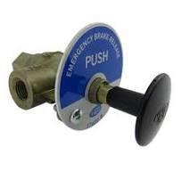
YARD RELEASE VALVE
TRT trailers are fitted with a Yard Release valve. This valve allows the brakes to be released using the existing air in the brake reservoirs.
The yard release is used when shunting the trailer, without truck with a proper brake set-up.
PUSH the valve in to release brakes PULL the valve out to re-apply the brakes
Attaching a truck to the air couplings at the front of the trailer re-sets the valve to allow the air tanks to be filled and the trailer brakes to operate in the normal manner
LANDING LEGS
This trailer has been fitted with RAZOR electric landing actuators. The landing legs are JOST.
The Controller is wired to a battery case, the battery is kept charged by a 9-30volt connection to the tractor unit through pins 3 (Earth) and 5 (Auxiliary +) OR 7 (Tail lights) This means that the landing legs can be operated electrically without a tractor unit attached to it.
The electric control unit also still has use of the landing legs gear set. By pulling the controller out, or pushing it in, (as you would do with a manual crank handle) the gear ratio controlling the leg speed is changed.
IN = high speed – low torque OUT = Low speed – High torque
To operate the Razor electric landing legs.
4. Turn the unit ON by pressing and holding the RED button for about 3 seconds
5. Arrow UP = legs up
6. Arrow Down = Legs down
The leg controller has. Buttons on it to turn it ON and OFF and to control UP and DOWN direction.
LUBRICATION
This trailer is fitted with an integrated greasing system. The system uses standard EP grease.
The Ball race on top of the kingpin has a number of grease nipples at the front right side of the skidplate assembly. Each grease nipple is attached by a hose to the various points on the ball race.
There is a row of 4 grease nipples at the rear Suspension isolation valve for axles 3&4. It is located directly behind the Stainless steel cover.
The ramps have a grease block at each ramp.
The grease blocks meter the grease to the greased area, this is a progressive system.
For more information, please see the grease system in the maintenance section of this manual.
MAINTENANCE
Please check Manufactures Maintenance guidelines for non TRT components ie; axles, Steering, greasing systems, etc.
Where BPW axles are fitted please refer to BPW Operators Manual, supplied with Trailer Manual.
The BPW First Service Check should be completed, and form returned to BPW. (SEE NEXT PAGE)
MAINTENANCE SCHEDULE
Daily
Operator to check
- Visual check for damage
- Check for air, hydraulic oil, or grease leaks
- Drain air tanks
- Check auto greaser for grease level.
Two Weekly
- Check that tyre pressures are correct
- Check all lights operate
- Check that wheel nut torque values are correct
- Check brake adjustment and re-adjust as necessary
- Grease all grease points that are not auto greased. (ramps etc)
- Ensure that skid plate has sufficient grease
- Wash trailer
Three Monthly
- As per two weekly checks
- Check wheel bearing play and re-adjust as necessary
- Check brake shoe wear and replace as necessary
- Check wheel nut torque and wheel alignment
- Check S cam bushes for wear and replace as necessary
Six Monthly
- As per three monthly checks
- Check tyre wear on all axles
- Rotate the tyres on all axles to ensure even tyre wear
- Check brake drum wear and replace as necessary
- Obtain C.O.F.
Twelve Monthly
- As per six monthly checks
- Check wheel bearings
- Check S cams for wear and replace as necessary
- Replace drop out king pin as per regulations (For NZ trailers only)
- Replace wheel bearing grease – see wheel bearing section for maintenance and procedure
- Obtain new registration
BEFORE OPERATING TRAILER: King Pin must be amply greased with E.P. grease with MoS2 or graphite additive. Sufficient greasing of King Pin and fifth wheel coupling is most important for the lifetime of both components.
NOTE: WHEEL NUTS MUST BE TORQUED AFTER THE FIRST 100km. AUSTRALIAN TRAILERS MUST HAVE THE WHEEL NUTS TORQUED BEFORE LEAVING THE PORT.
WARNING
TRT HYDRAULIC SUSPENSION
When lowering the trailer, the power pack or PTO must be operating. This will ensure that both sides of the suspension cylinders are full of oil. Damage to these cylinders may occur if this instruction is not adhered to.
Lowering the trailer without the Power Pack running or PTO engaged will cause air / vacuum to be drawn into the spear side of the cylinder.
Failure to operate the trailer in the correct manner will void warranty.
SUSPENSION
The hydraulic compensating suspension system on the trailer enhances stability and load management, particularly when dealing with uneven weight distribution. This technology allows each side of the trailer to adjust independently, ensuring smoother transport and reducing wear on the vehicle and cargo.
Inspection points on the suspension are limited to observing wear or Damage in the trailing arm pivot bushes
The ‘Frampton Joints’ at each end of the suspension ram also need monitoring for wear. If they are kept greased they have a long service life.
Occasionally a suspension ram seal will fail. The indicator for this is the trailer slumping on one side. The load (counterbalance Valve) in each suspension line can also Give the impression of a failed seal so diagnostic testing Is required to pinpoint the area of failure. A cylinder test procedure is available near the back of this manual.
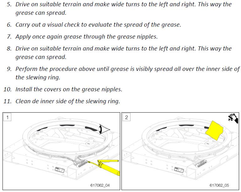
GREASE SYSTEM
The Ball race on top of the kingpin has a number of grease nipples at the front right side of the skidplate assembly. Each grease nipple is attached by a hose to the various points on the ball race.
There is a row of 4 grease nipples at the rear Suspension isolation valve for axles 3&4. It is located directly behind the Stainless steel cover.
The ramps have a grease block at each ramp.
The grease blocks meter the grease to the greased area, this is a progressive system.
For more information, please see the grease system in the maintenance section of this manual.
BRAKES AND WHEEL BEARINGS
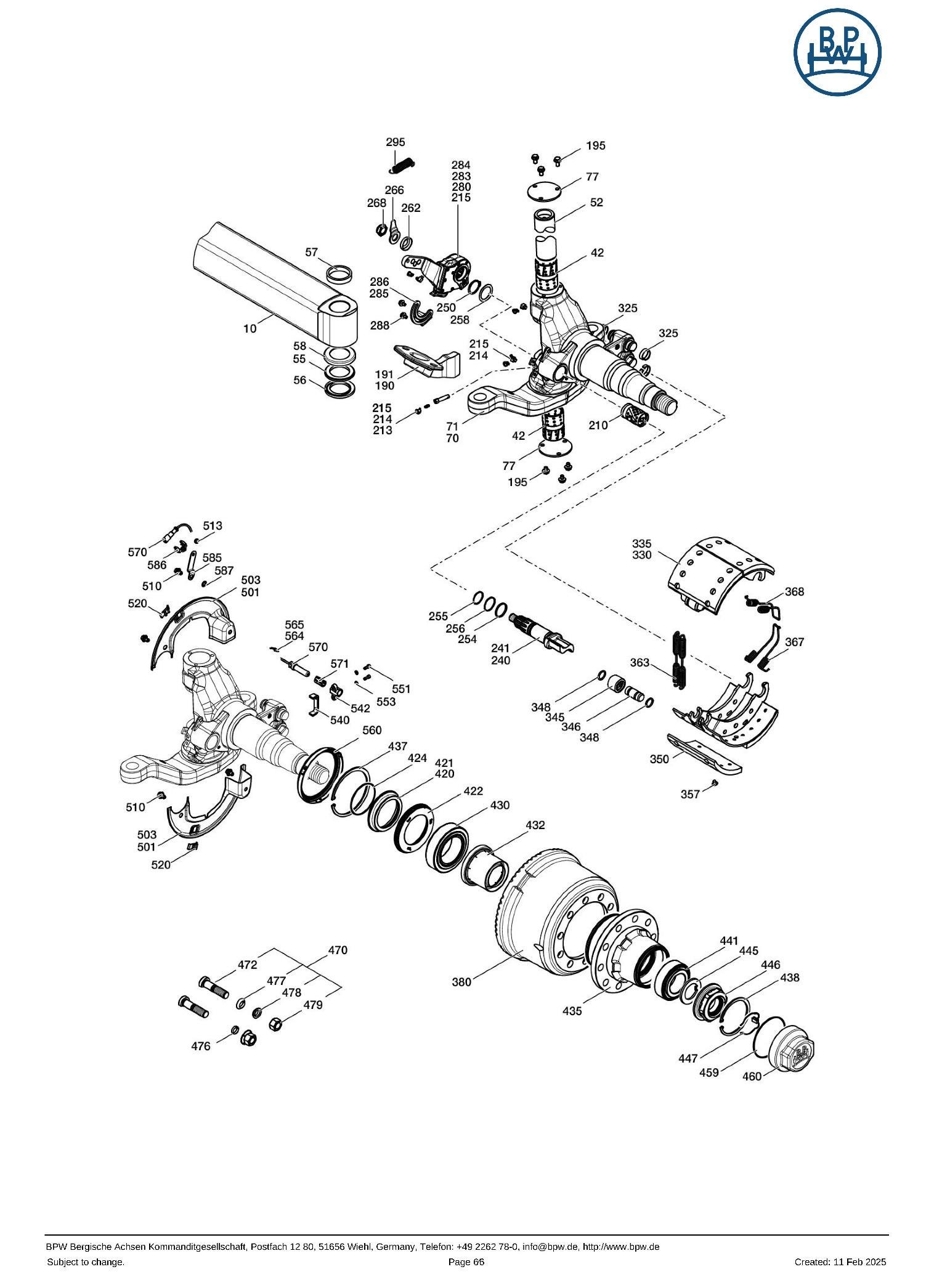
The axles and brakes on this trailer are BPW 29.70.11.0350 The slack adjusters are auto adjusting units, but they can be manually overridden if required. The axle parts list is supplied later in this manual.
A list of special tooling required for your axle is available from your BPW supplier. He will require information from the axle tag or model information from this manual.
Following this page is a selection of general maintenance pages for drum brakes. A full workshop manual for BPW Drum Brakes is available from your local BPW supplier
STEERING
The steering system in this trailer is supplied by TRIDEC. A comprehensive service manual is available at www.tridec.com
When ordering parts please supply the Trailer VIN number and TRIDEC part number (SV-2040-TFXVG)
The original TRIDEC drawing number is 53495834
LUBRICATION:
There is a manifold of grease nipples on the front right side of the kingpin turntable. All other pivot mechanisms and tie-rod ends are sealed.
LANDING LEGS
PARTS LISTS
MAJOR COMPONENTS
Steer Axles
Hydraulic Suspension
Rims (Chromed alloy)
Rims (Alloy)
Tyres
Brake Kit
Trailer King Pin 2”
Steer System
Suspension Ram
Swing Arm Bush
Suspension Ram Eye Kit
Widening rams
Ramp Rams
Lights
BPW 10 stud 17.5 (BW 26.50.502.181-182)
Tidd Hydraulic
AMARC223-26
TRT ALLOY
235 / 75R 17.5” Tubeless radials
AMEBSE04B
TDKP0406005
TRIDEC SV-2040-TFXVG
HYD55-01 (B) 90mm x 50mm x 133mm
TM62624 LMXP M30x150 x78
TDHYD17-A3RK
TDHYD56-001 3.5”x1.75x500
TD011-A7 3”x1.5”x16”
LED (See lighting diagram)
Motor Yanmar L48AE-DE
Coupling
Pump
Woodruff Keys
Winch Valve
Widening and Suspension
ND 510
AM1APA2.5D10GG
HY01009642999
Q45M/1
Q45 M/7 Galtech
Detent Kit
Widening and Ramp Valve
Pneumatic Actuators
Suspension Lock Valve
Counterbalance Valves
Hoses & Fittings
Return filter element
Pressure Filter
Pressure Transducer
HY03750R10Z1 on Ramp Spool
HY03661 P1N
TDLVASS
HYCBPA08
HYDRAULINK
AMFTFE 1810
HYHPM421F10XNR
ELPU8501
BRAKES
(The Brake Schematic is located at the rear of this manual)
Part No. Description
RW2424SB SPRING BRAKE
ABR408 AIR TANK – Ø245mm
TAR514 AIR TANK – Ø335mm
SL110701 SPRING BRAKE CONTROL VALVE
SL110360 SERVICE RELAY VALVE
480.102.080.0 EBS MODULATOR
SA0964615 DRAIN VALVE
SL 17600B YARD RELEASE VALVE
BW0517488822 SLACK ADJUSTER LH
BW0517488823 SLACK ADJUSTER RH
LIGHTS AND SIGNS
Part No.
Description
1217R-2 STOP / TAIL LAMP (PATERSON LED – ROUND)
1217A-1 INDICATOR LAMP (PATERSON LED – ROUND)
HA 2053 LED SIDE MARKER RED/AMBER
HA2054 FRONT MARKER (CLEAR)
HA2919 AMBER REFLECTOR
HA2559 LED LICENSE PLATE
HA2031 SIDE INDICATORS
HA2926 RED REFLECTOR
HA2921 CLEAR REFLECTOR
ELBCN01A BEACON LAMP 24V
HA1563 REVERSING LAMP
AMTDRO8201 LED WORK LIGHT
CIXT037/A-CAT 31L DO NOT OVERTAKE TURNING VEHICLE
CIXT027/A DELINEATER PLATE (2 OFF)
CIXT008/A OVERSIZE (2-PIECES)
LIGHTING DIAGRAM
RAZOR PARTS
AXLE PARTS – STEER
TEST AND INSPECTION PROCEDURES
SUSPENSION RAM SEALS – TEST PROCEDURE
1. Raise the Trailer to full height
2. Lock off all Suspension lock valves. OPEN 1 suspension lock valve for ram to be tested.
3. Remove the BASE hose from the ram side of this lock valve fitting, (A little pressure may be evident) and CAP THE LOCK VALVE FITTING
4. Fit a PLUG to the BASE HOSE but leave it quite loose. Cap Plug
5. Start the power pack up (suspension isolation valve in Adjust suspension position) and raise the wheel off the ground to about 1/3 the stroke of the ram. (Oil will be pushed out the loose plug)
Test 1:
Stop the power-pack, return the suspension isolation valve to the travel mode, and observe the ram spear. 10 minutes If the ram extends under the weight of the wheels and axle the seals are damaged
Test 2:
If the ram passes on test 1, tighten the plug on the BASE hose to stop any further oil escaping. Restart the power pack and Open the Suspension isolation valve. For the side of the trailer being tested, push the suspension control lever DOWN and hold it in this position while observing the suspension ram. The ram will attempt to lift the wheels further off the ground but will be unable to due tothe basehose being capped. Expect the ram to close a little, but if it then starts to EXTEND the seals are damaged.
NOTE: Repeat tests 1 and 2 at ½ and ¾ stroke positions on the ram, as a ‘bulged’ or ‘scored’ ram can produce the same symptoms.
Theory of test 2
Oil is forced into the spear end of the ram and attempts to push the piston upwards; this movement is resisted by the capped hose on the port at the base of the cylinder preventing oil above the piston from escaping.
1. If the piston seals are serviceable the piston will stall and the oil will be forced over the relief setting at the control valve.
2. If the piston seals are damaged the oil will bypass the seals and cause the rod to SLOWLY extend from the ram. This happens because the base end of the piston has a greater surface area than the surface area of the spear end. When the same pressure is exerted on the two unequal areas, a greater force is present on the larger face, causing the ram to extend.
In the event of 1 (or more) ram(s) in a suspension side having damaged seals the side effected will be slower to operate (or may fail to lift the trailer) due to the by-passing oil. When all suspension lock valves are open but the Isolation valve is closed the oil will slowly equalise both sides of ALL the cylinders on that side of the trailer but the trailer will ‘Droop’ on the side affected.
Plugged
Base End
Spear End
Worn seals allow oil
By-pass
ASSEMBLY – LOCK and ISOLATION VALVE
Over the course of time the Lock Valve mechanism can fail due to wear in the drive ‘biscuit’ or a valve seizing.
Valve function check if failure is suspected
- Make trailer safe by lowering onto dunnage, turn power pack off and manipulate control handles to deplete any residual pressure in the suspension lines.
- Remove the hoses from 1 end of the lock valve and, with the valve in the open position; attempt to pass a (clean) rod through the valve. (It should pass through both sides of the valve)
- Repeat the above test with the valve in the closed position
- If failure is proven remove and strip the valve for repair.
Reassembly notes
- Check that BOTH valves open and close and are not in any way seized or seizing.
- Start assembly with both valves in the open position
- Carefully position the limit plates to allow the valve to operate through it required motion.
- inspect the drive biscuit for wear in the square and the handle thread, replace it required.
- Reassemble and check operation before fitting to trailer.
- Check that the valve operates correct to the instruction decals
BRAKE SCHEMATIC
HYDRAULIC SCHEMATIC
TORQUE CHART
TORQUE VALUES in Nm for ft/lb multiply by .74
All bolts must be coated with rescue steel or loctite