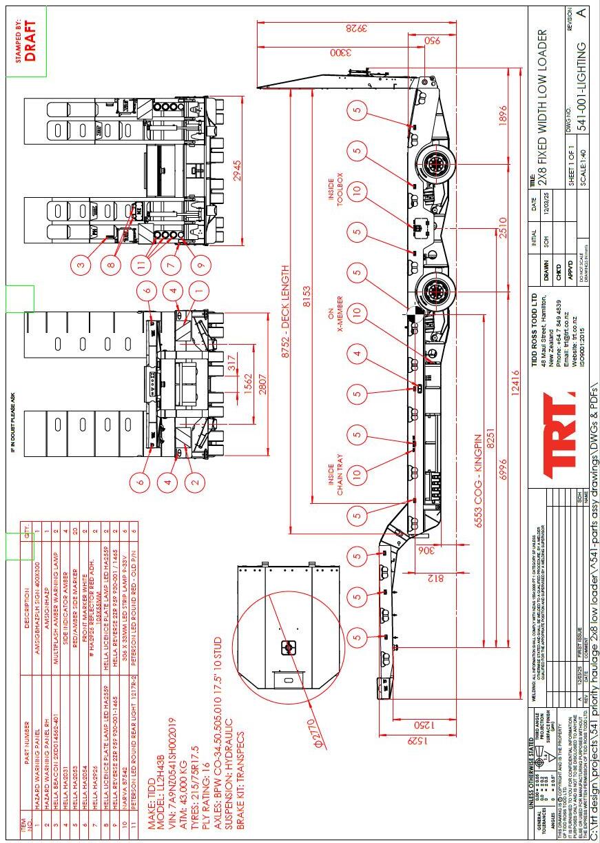


SPECIFICATIONS
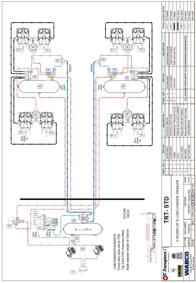
TRAILER DRAWING 541-001 J/N P000728
VIN 7A9NZ0541SH002019
TRAILER GVM 43000 KG
TRAILER TARE 8840 KG
AXLE SPACING 2510mm
AXLE TYPE
AXLE MODEL
WHEELS

TRAILER DRAWING 541-001 J/N P000728
VIN 7A9NZ0541SH002019
TRAILER GVM 43000 KG
TRAILER TARE 8840 KG
AXLE SPACING 2510mm
AXLE TYPE
AXLE MODEL
WHEELS
Service
Please contact the TRT service department if you have any questions about your trailer. Please list the model number and Vehicle Identification Number (VIN) in all correspondence.
Technical Support
Contact your local distributor.
Supplied Trailer Information
Supplied documentation (electronic) comprises the following: Operating Procedure, Risk Analysis, Rated Capacity, Parts Catalogue and Service Manual.
Modifications to the Trailer
Any modifications made to the Trailer must be approved by manufacturer. Failure to gain written approval will void warranty.
Vehicle Identification Number (VIN)
When corresponding with the manufacturer the VIN should be included, it will be used to identify the trailer. (VIN is located at the front of the trailer.)
Manufacturer
TRT Tidd Ross Todd Ltd 48 Maui Street
Pukete Industrial Estate
Hamilton 3200, New Zealand
Phone: +64 7 849 4839 Fax: +64 7 849 3628 trailers@trt.co.nz www.trt.co.nz
TRT Australia
1028 Lytton Road, Murarrie, QLD 4172
Australia
Phone: +61 7 3890 8800
AU Parts: parts@trtaust.com.au
AU Service Group: service@trtaust.com.au www.trtaustralia.com.au
Thank you for choosing a TRT product, the use of the trailer should be as efficient and as safe as possible by you as an owner and or operator by following the guidelines below:
• Do not operate this trailer until this manual has been read and fully understood.
• Comply with:
a) Health and safety regulations.
b) Local regulations.
• Understand and follow the instructions in this and other documents supplied with this product.
• Use common sense and perform safe working practices.
• This trailer should only be operated by a trained operator, directions should come from an informed, knowledgeable source.
If there is information or data missing from this product please contact your local distributor.
The safety of the operator and the people in the vicinity of the trailer is your priority.
The safety of TRT product users is of paramount importance, bulletins are one of the means used to communicate important safety and other relevant information to the dealers and TRT product owners.
The information contained in the bulletins is specific to the trailer model and serial numbers.
The bulletins are distributed via registration information from the dealer/owner. It is very important to keep the contact information up to date to in order to receive important updates. To ensure the safe operation and longevity of the trailer the bulletins information actions should be complied with.
When the manufacturer needs to be contacted, be ready to supply the model and serial numbers of your trailer, along with your name and contact information. At a minimum, the manufacturer should be contacted for:
• Accident reporting.
• Questions regarding product applications and safety.
• Standards and regulations compliance information.
• Questions regarding product
• modifications.
• Current owner updates, such as changes in trailer ownership or changes in your contact information (see transfer of trailer ownership below).
Address: 48 Maui Street, Pukete Industrial Estate 3200, Hamilton, New Zealand.
Phone: +64 7 849 4839 (NZ)
Email: trailers@trt.co.nz
If you are not the original owner, contact the manufacturer as soon as possible with details including:
• Serial number.
• Name of new owner.
• Date of ownership transfer.
This will ensure any relevant information is received in a timely manner.
When lowering or raising the trailer, the PTO must be engaged before operating.
This will ensure that both sides of the suspension cylinders are full of oil.
Damage to these cylinders may occur if this instruction is not adhered to.
Lowering the trailer without the PTO engaged will cause air / vacuum to be drawn into the spear side of the cylinder.
Failure to operate the trailer in the correct manner will void warranty.
DO NOT PRESSURE WASH the electrics on this Trailer
Do NOT blast pressurized water into brake valves
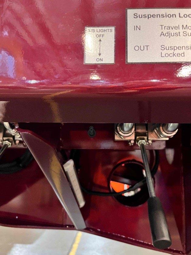
When working under the trailer ensure ALL suspension lock valves are in the locked position


Major components of this trailer are made from GRADE 80 High
Tensile steel, PREHEATING BEFORE WELDING is essential to avoid post welding cracking.
Please contact TRT for welding procedures and consumable specifications before welding.
TRT NZ
07 849 4839 0800 878 695
Brennan Rietema TRT Design
David Tynan TRT Engineer
Failure to contact TRT to gain the proper weld procedure could cause additional failures and may result in the warranty being voided.
The incoming services for the trailer are located at the front of the gooseneck.
Brakes Duomatic coupling Lights 7-pin socket
A flow control valve has been fitted in the gooseneck area under the top deck. This valve determines the speed at which the trailer operates it is adjustable between no flow to the trailer (0) and full flow to the trailer (up to 10). Full flow may be reached at a lower number than 10 if the trucks pump does not flow to the capacity of the flow control (80l/min)
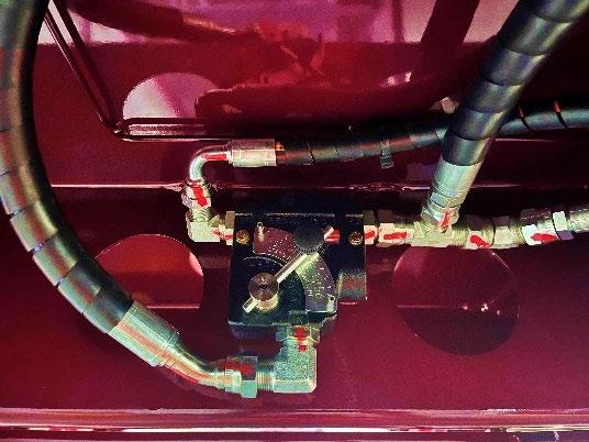
Adjust the flow to a level that has the ramps raising at a manageable speed.
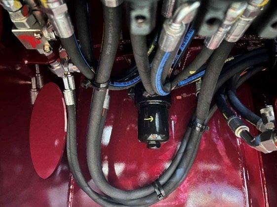
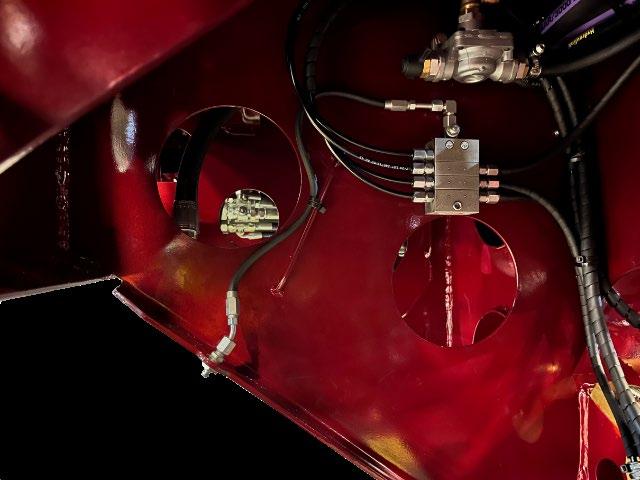
The hydraulics on the trailer are protected by a pressure filter. The pressure filter is located at the left side of the trailer in the same area as the Hydraulic control station is located
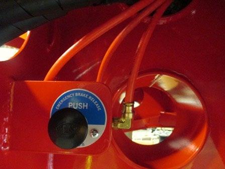
A yard release valve for the brakes is located on the RIGHT side of the railer, ahead of axle 1
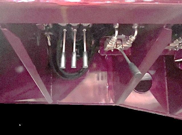
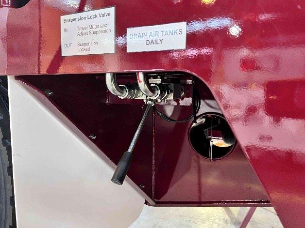
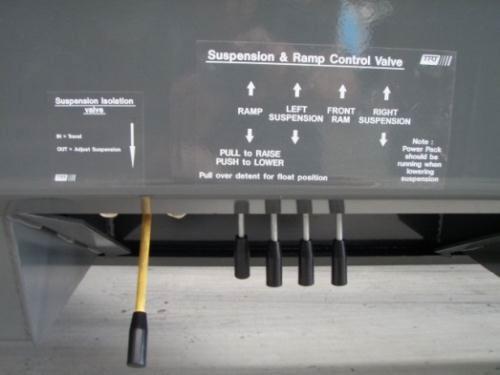
The Hydraulic control station is located under the main deck, on the left side of the railer, ahead of the 1st axle line. This control station controls the suspension and the ramps
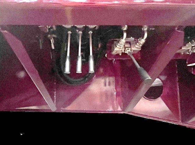
The suspension Isolation Valve is located at the hydraulic control station. Its purpose is to isolate the weight of the trailer being held in the suspension rams and hoses from the suspension valve. The isolation valve must be OPEN (pulled Out) to adjust the trailers desk height.
The suspension Lock valves are located at each wheel group. Their purpose is to Lock the ram from operating if the control valve is operated.
If an axle has to be carried it can be isolated in the UP position
If the trailer is being worked under, the trailer can be made safe by raising the trailer and locking all the suspension lock valves.
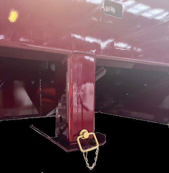
A pair of drop-down landing legs are fitted to the front outside corners of the lower decks. These landing legs are supplied to support the trailer when it is detached from a tractor unit.
IF the trailer is loaded, and the tractor unit needs to be removed, additional support is required under the gooseneck in line with the landing legs.
Each wheel group has a single grease nipple under the coaming rail. This single grease nipple is connected to a grease manifold the meters the grease inputted to the various outputs for each wheel group
The upper decks can be accessed using 2 ramps that can be pulled out of their retaining cavities under the top deck. The ramps are retained in position with a sprung ‘drop-latch’ under the top deck
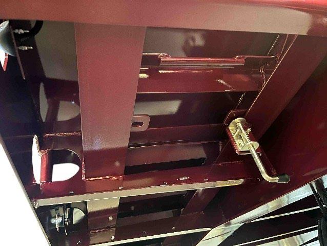
The ramp ‘tips’ have locating pegs that fit into a range of holes in the top deck.
Each ramp has a fold out section that completes the OVER SIZE sign.
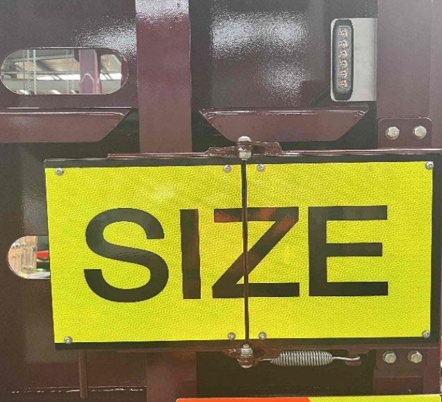
Each ramp has an extendable delineator fitted to it. The delineators have a range of positions from fully closed 3.6m overall width.
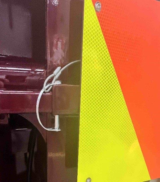
The front corners of the trailer have delineators fitted at the lower decks
On each occasion prior to using the transporter the following procedures must be carried out, to ensure the safe operation of the transporter and the safety of the personnel involved:
• Check that the C.O.F. and registration are current
• Ensure that the maintenance schedule is up to date
• Walk around the trailer to check for obvious faults such as:
- Tyres are all correctly inflated including the spares
- Wheel nuts and studs are tight with none missing
- No air leaks from hoses, tanks, valves or couplings
- No hydraulic leaks from rams, hoses or valves
- No structural cracks to chassis
- Wheel alignment is correct
• Check that the trailer kingpin is the correct size and is fully engaged with the 5th wheel and that all of the hydraulic, electric and air couplings are fitted correctly.
• Test that brakes and lights are fully operational.
• Ensure that load security devices, which will be required, are carried. This means dunnage and matting. These are to be stowed securely to prevent movement while travelling.
• Check that you have the required permits to cover the load intended.
• Check that the suspension is set to the correct height and that enough of the axles are fully compensating for the load that is to be carried.
• Check that the route has adequate ground clearance to that which the trailer has available. This is particularly important over railway lines and off road situations.
• Allow for road traction, which is significantly reduced, in wet or unsealed conditions.
• Be aware of weather conditions as these can affect the load. Rain and fog can reduce traction; increase stopping times and reduce visibility. High winds will affect the stability of the load. Hot conditions will increase tyre pressures and heat build-up within the axles.
The PTO must be on and the hoist control in the UP position to supply oil to the trailer.
2.2.1
The hydraulic suspensions in these trailers are robust, and operated correctly, will give many years of trouble-free use. The suspension is designed to travel about the mid-stroke of the ram to give maximum compensation for terrain conditions. The suspension has double acting rams and can therefore be driven up or down depending on the required ride height. Set this to suit the terrain allowing for axle movement.
All axles have the capability of being locked in position. It is important to note that when in the lock position the axle will not compensate for the load being shared across the trailer.
Do not lock axles off when there is a possibility that the axle rating will be exceeded.
Each side of the trailer suspension is able to be raised or lowered independently using the levers at the hydraulic control station. Care must be taken to ensure that when raising or lowering that the load does not over centre and tip the trailer
suspension height and read the weigh gauge.
To raise an axle, lower the trailer to the lowest position, set the valves on the left hand and right-hand corresponding suspensions to the lock position and then raise the trailer to the ride height. The locked axles will remain in the raised position until the valve is unlocked.
Do not unlock the axles when raised as these will drop suddenly and damage the components or cause trailer to tip and loose load
Only have the suspension fully raised or lowered when the trailer is stationary
Be aware that when raising and lowering the suspension that there is rearward and forward movement respectively of the trailer. (dock walk)
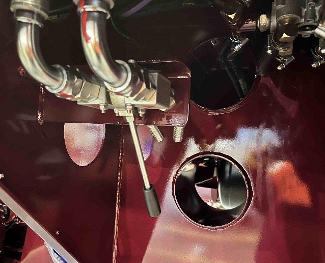
A suspension Isolation valve is fitted to protect the control valve form ‘hydraulic spikes’ It must be pulled OUT to adjust the


Never raise or lower the trailer while resting on landing legs as these may collapse.
After you have finished, always set the Isolation valve back to travel mode, otherwise damage could occur to the control valve.
• Ensure that the transporter is on flat even ground and that you have sufficient space behind the transporter to load in a straight line.
• Apply the truck and trailer brakes
• Engage the PTO.
• Lower the trailer suspension Do not lock off individual axles or damage may occur.
• Remove the ramp securing chains and lower the ramps ensuring that no personnel or equipment are in the way, (Note the ramp cylinders are double acting and you power the ramps up or down).
• The ramp rams have Ramp Lock Valves fitted to the ramp rams, These valves must be OPEN for the ramps to operate

• Leave the ramp controls in the detented ‘Float’ position when they are on the ground (to do this quickly move the handle up past the raise position and over the detent) or damage to ramp rams will occur.
The ramps must be in full contact with the ground and bear evenly on each side of the transporter. When loading, the ramp valve must remain in the detented ‘float’ position
• Dunnage should be placed under the rear of the chassis for loads over 20t
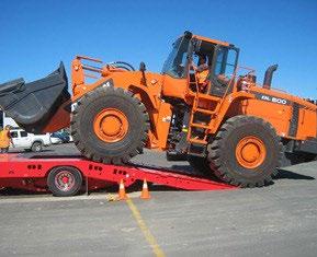
• Load the machine according to manufacturer’s instructions. Care is to be taken at the apex of the beavertail, as the machine may become unstable. It may be necessary to use a winch to assist the loading at this stage. Position the machine to not exceed the permitted axle loading.
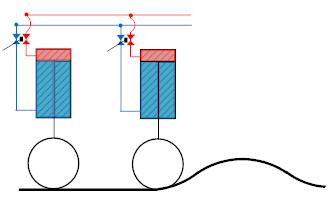
Suspension fully lowered
• Secure the load as required by the Restraint of Load Regulations
• Raise the ramps to the vertical position ensuring that they are clear of the load. The valve must remain in the mid-position once the operation is complete.
• Secure the ramp Twitches. Do not over-tighten
• Raise the suspension until deck is at ride height, Isolate suspension
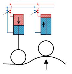
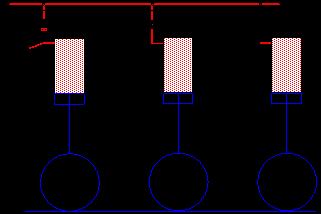
The oil cannot transfer as there is no stroke left in the rams that the oil is trying to transfer INTO.
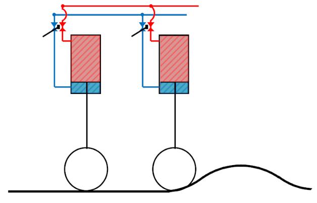
Rams are extended too far
(There is too much oil to transfer to the other full rams.)

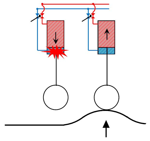
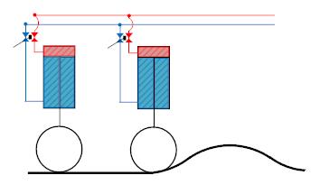
In this example all the load is taken on the first axle, the other axle sets are carrying no load.
WARNING! In this scenario the trailer could break its back!
As the trailer progresses over the hump the load is transferred to each axle independently in turn. In all cases only ONE Axle set carries the load putting high point loads into the trailer chassis.

In this example, oil tries to transfer to the other ram, but the 1st ram bottoms out. This causes the whole trailers load to be carried on 1 axle
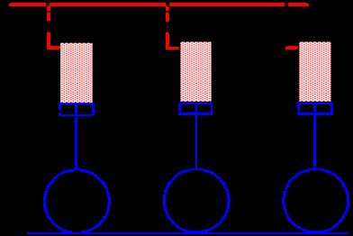
Oil is able to transfer from ram to ram as suspension ‘walks’ over rough terrain. If a wheel runs over a hump the oil will pump from that ram into the other rams that are able to accept the volume of oil
Direction of Travel
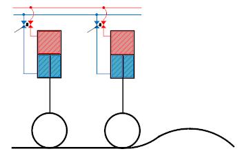
Direction of Travel
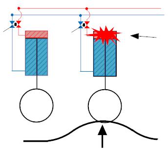
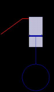
As this is only a 2 axle trailer it is not recommended to lift an axle while traveling.
On the occasion of having to ‘carry’ a wheel set, extreme care needs to be taken to not overload the remaining axle that is on the ground
As the wheel runs over the obstacle, it compresses the ram which pumps oil into the other ram. This raises the trailer a little.
1: Lower the trailer all the way down
2: Lock off the wheel group that needs to be carried. (not the whole axle row)
3: Raise the trailer back to ride height
Caution:
The hydraulics being able to lift the trailer does not indicate that the trailer is within the safe its safe axle rating
2.3.1
Ensure that the trailer is on a flat even surface and there is at least 10 metres of clear space behind the trailer for loading when using the ramps. The surface behind the transporter should not be lower than the transporter wheels or you may damage the ramps.
Operation
• Place the trailer brakes in the parked position and start the PTO
• Lower the trailer suspension completely down so that the chassis is on or near the ground, using the suspension control levers.
• Check the ground below the rear wheel cut-out area is clear of any obstruction (IE: the ground is flat)
• Ensure the ramp lock valves are open
• Release ramp restraints.
• Go to the ramp control valve and operate lever in the down position to power the ramps down. (the ramp tips deploy as the ramps are lowered)
When they are on the ground PUSH the ramp lever passed the Down position and over the detented FLOAT POSITION
• Load the equipment onto transporter and secure
• Go to ramp control valve and operate lever to raise ramps
• Place the control valve in the central position IE: NOT detented!! (important).
• Replace the ramp restraints and secure.
• Raise the suspension to travel position.
• Place Hydraulics in travel mode

Always lower suspension before deploying ramps, otherwise damage to the ramp rams or their mounts could occur

2.3.2 Beacons
The flashing lights on each beacon is switched on or off using a toggle switch located in the taillight mount

The ramps to the upper deck are stover under each side of the upper deck and retained in place with a spring-bolt.

Release the spring bolt and slide the rams out of their carriers
Determine the correct width of the ramp spacing required and locate the ramp pegs into the holes in the upper deck.

There is a light on each side of the trailer, ahead of the 1st axle line. These will come on when reversing
2.3.5
There is a switch at the control station that turns on the Toolbox lights.

Return the rams to their stowed location and retain them in place with the spring bolt before traveling
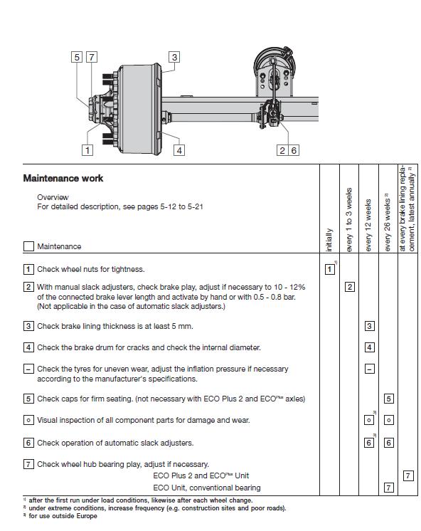
Daily
Operator to check
- Visual check for damage.
- Check for air and hydraulic oil leaks.
- Drain air tanks
-
Two Weekly
- Check that tyre pressures are even and correct.
- Check that wheel nut torque values are correct.
- Check brake adjustment and re-adjust as necessary.
- Grease all grease nipples.
- Ensure that skid plate has sufficient grease.
- Wash trailer.
Three Monthly
- As per two weekly checks
- Check wheel-bearing play and re-adjust as necessary.
- Check brake shoe wear and replace as necessary.
- Check wheel nut torque and wheel alignment.
- Check S cam bushes for wear and replace as necessary.
Six Monthly
- As per three monthly checks
- Check brake drum wear and replace as necessary.
- Check tyre wear on all axles.
- Obtain C.O.F.
Twelve Monthly
- As per six monthly checks.
- Check wheel bearings and replace wheel bearing grease.
- Check S cams for wear and replace as necessary.
- Replace drop out king pin as per regulations.
- Obtain new registration. BEFORE OPERATING TRAILER: King Pin must be amply greased with E.P. grease with MoS2 or graphite additive.
Sufficient greasing of King Pin and fifth wheel coupling is most important for the lifetime of both components.
3.2.1
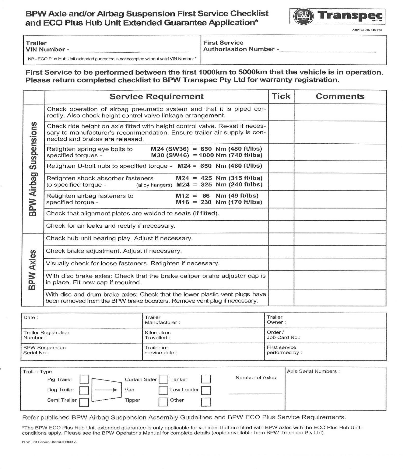
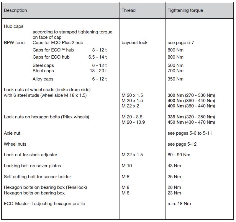
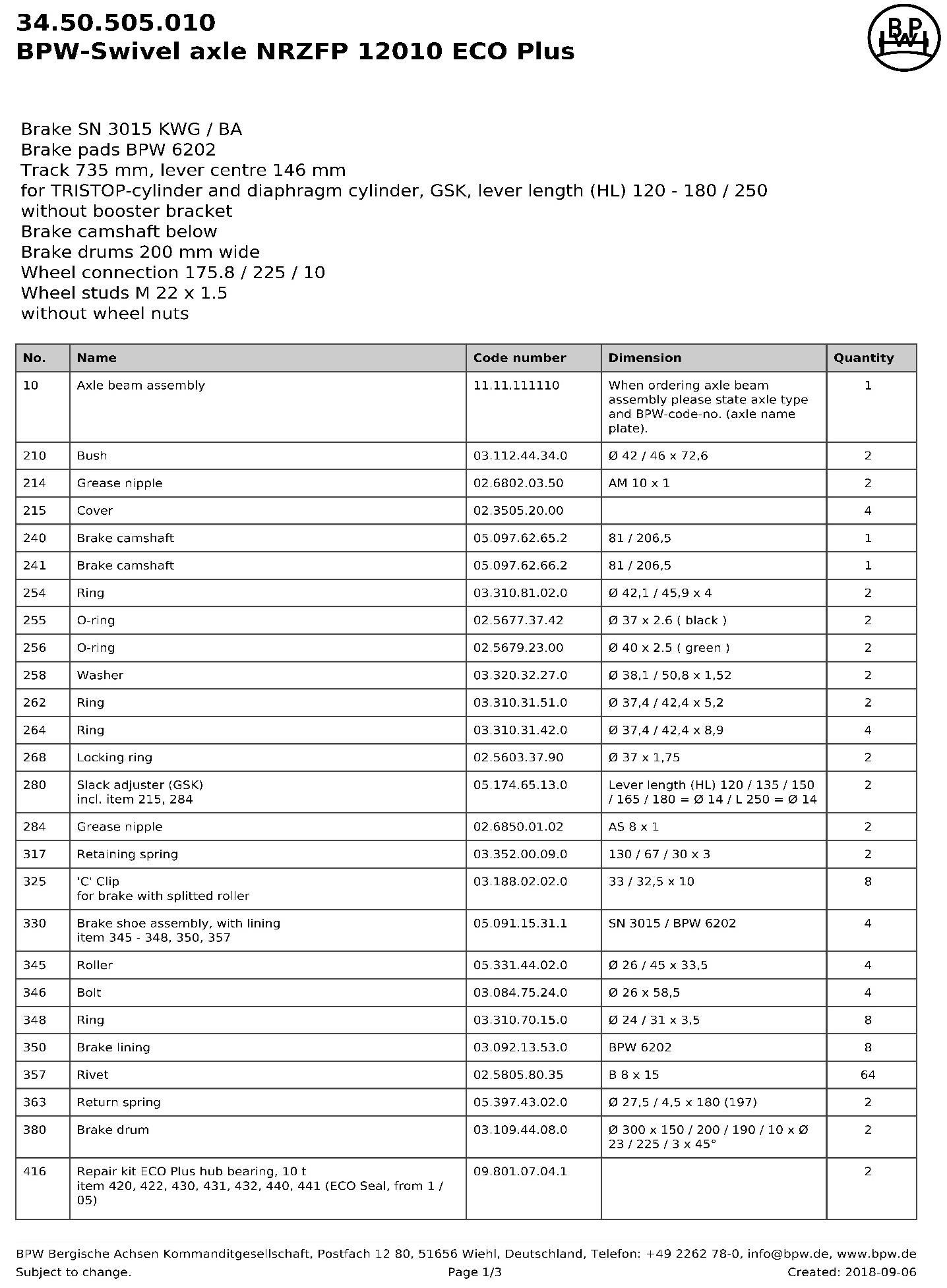
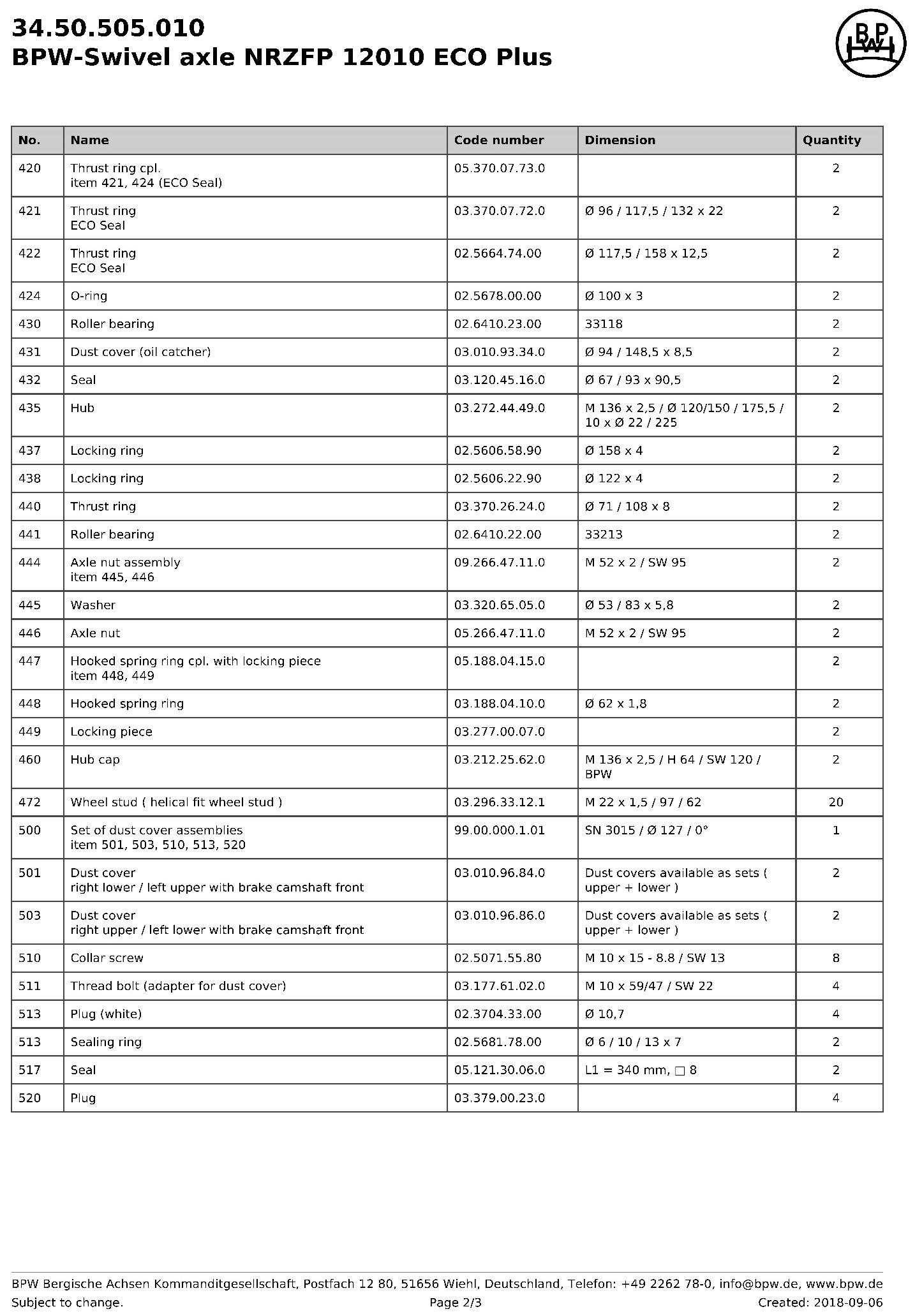
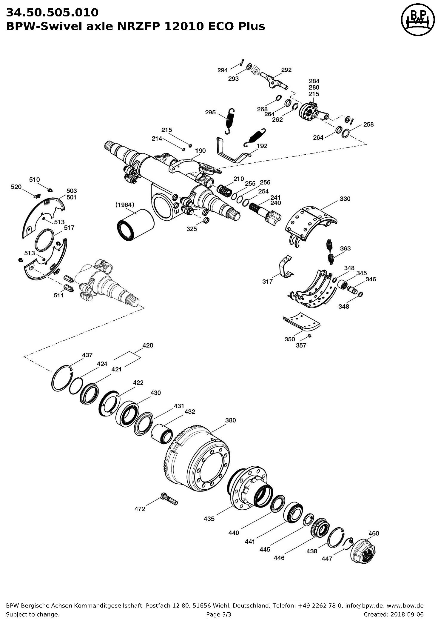
3.2.2 BPW: Tightening Torques

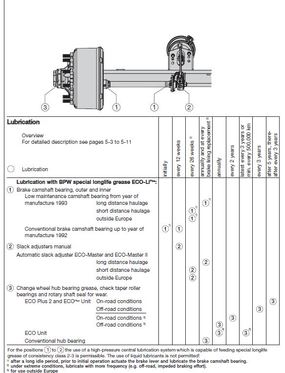
3.2.3 BPW - Librication
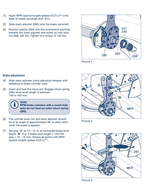
3.2.5 BPW Brake Adjustment
4.1
COMPONENT DESCRIPTION
Trailer Axles
Trailer Suspension
Wheel Rims
Tyres
PART NUMBERS
BW3450505010
TRT HYDRAULIC
ALLOY – PMT167A
KIWI17-215
Kingpin 2”
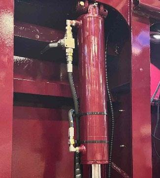
Suspension rams
Suspension ram Ball end
Suspension ram Dog-bone end
Suspension Guide Block
Suspension Pivot Bearing
Suspension Pivot Int. Circlip
Ramp Rams
Suspension control valve
Detent kit
Hoses and Fittings
HYD49-001-D1
HYD49-001-003
TDROECOLLETT SET
OILY BUSH 145 x 145 x 83 x Ø71 Hole
TKGE70DO (70mm Dia.)
TKIC105 (105mm Dia.)
4 x 2 x 16
Q45M/3
Q45R8DT
HYDRAULINK
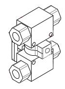
Over the course of time the Lock Valve mechanism can fail due to wear in the drive ‘biscuit’ or a valve seizing.
Valve function checks if failure is suspected
• Make the trailer safe by lowering onto dunnage, turn the PTO off, and manipulate control handles to deplete any residual pressure in the suspension lines.
• Remove the hoses from 1 end of the lock valve and, with the valve in the open position: attempt to pass a (clean) rod through the valve. (It should pass through both sides of the valve)
• Repeat the above test with the valve in the closed position.
• If failure is proven remove and strip the valve for repair.
• Check that BOTH valves open and close and are not in any way seized or seizing.
• Start assembly with both valves in the open position
• Carefully position the limit plates to allow the valve to operate through it required motion.
• inspect the drive biscuit for wear in the square and the handle thread, replace it required.
• Reassemble and check the operation of the valve before fitting it to trailer.
• Check that the valve operates correctly to the instruction decals.
To check operation of Lock Valves and Suspension Isolation valve:
1. Ensure trailer is supported on dunnage under the chassis rails.
2. Release all line pressure in suspension lines by operating suspension control levers up and down with power pack OFF, Suspension lock valves open, and Suspension Isolation valve in the Adjust Suspension position.
3. Remove the hoses from one end of lock valve.
4. Try to pass a (clean) welding rod, wire etc. through Valves. If it passes through 1 but not the other in the pair, they are out of ‘phase’ (often caused by the ‘biscuit between the valves rounding off the drive square due to a seizing ball valve).
5. If the valve is out of phase it will need to be removed, dismantled and corrected. (Drive biscuit replaced if worn and ball valve un-seized or replaced) Remove the 4 bolts through the backing plate and separate the ball valves from the drive biscuit. Observe and orientate both ball valves to the open position, refit the ‘stop washers’ in the correct position to allow handle movement, and refit the valves to the drive biscuit. Refit the backing plate and test for operation before refitting to trailer.
NOTE:
When reassembling the unit, make sure the handle is in the correct position for open and closed according to the decals on the trailer.
1. Raise the Trailer to full height
2. Lock off all Suspension lock valves. OPEN 1 suspension lock valve for ram to be tested.
3. Remove the BASE hose from the ram side of this lock valve fitting, (A little pressure may be evident) and CAP THE LOCK VALVE FITTING.
4. Fit a PLUG to the BASE HOSE but leave it quite loose.
5. Start the power pack up (suspension isolation valve in Adjust suspension position) and raise the wheel off the ground to about 1/3 the stroke of the ram. (Oil will be pushed out the loose plug)
Test 1:
Stop the PTO, return the suspension isolation valve to the travel mode, and observe the ram spear. If the ram extends under the weight of the wheels and axle the seals are damaged.
Test 2:
If the ram passes on test 1, tighten the plug on the BASE hose to stop any further oil escaping. Restart the power pack and Open the Suspension isolation valve. For the side of the trailer being tested, push the suspension control lever DOWN and hold it in this position while observing the suspension ram. The ram will attempt to lift the wheels further off the ground but will be unable to due to the base hose being capped.
Expect the ram to close a little, but if it then starts to EXTEND the seals are damaged.
NOTE: Repeat tests 1 and 2 at ½ and ¾ stroke positions on the ram, as a ‘bulged’ or ‘scored’ ram can produce the same symptoms.
Oil is forced into the spear end of the ram and attempts to push the piston upwards; this movement is resisted by the capped hose on the port at the base of the cylinder preventing oil above the piston from escaping.
1. If the piston seals are serviceable the piston will stall and the oil will be forced over the relief setting at the control valve.
2. If the piston seals are damaged the oil will by-pass the seals and cause the rod to SLOWLY extend from the ram. This happens because the base end of the piston has a greater surface area than the surface area of the spear end. When the same pressure is exerted on the two unequal areas, a greater force is present on the larger face, causing the ram to extend.
In the event of 1 (or more) ram(s) in a suspension side having damaged seals the side effected will be slower to operate (or may fail to lift the trailer) due to the bypassing oil. When all suspension lock valves are open but the Isolation valve is closed the oil will slowly equalize both sides of ALL the cylinders on that side of the trailer but the trailer will ‘Droop’ on the side affected.
TORQUE VALUES in Nm for ft/lb multiply by .74
All bolts must be coated with rescue steel or loctite
Bolt up King-pin
-
-
-
Brake Chambers - 190Nm
Wheel Nut (M22 x 1.5) - 600Nm
ALL Brake Chambers must have Nyloc Nuts and Hardened Washers