


Service
Please contact the TRT service department if you have any questions. Please list the model number and Vehicle Identification Number (VIN) in all correspondence.
New Zealand
Phone: 07 849 4839
Email: service@trt.co.nz
Emergency Call Out 24/7
Phone: 0274 726 394
Technical Support
Contact your local distributor.
Modifications to the Trailer
Any modifications made to the Trailer must be approved by manufacturer. Failure to gain written approval will void warranty.
Vehicle Identification Number (VIN)
When corresponding with the manufacturer the VIN should be included, it will be used to identify the trailer. (VIN is located at the front of the trailer.)
Manufacturer
TRT Tidd Ross Todd Ltd
48 Maui Street
Pukete Industrial Estate
Hamilton 3200, New Zealand
+64 7 849 4839 trailers@trt.co.nz www.trt.co.nz
V.I.N NUMBER: 7A9AS0535SH002013


When lowering or raising the trailer, the hydraulics must be powered up or down
This will ensure that both sides of the suspension cylinders are full of oil.
Damage to these cylinders may occur if this instruction is not adhered to.
Lowering the trailer without the PTO running will cause air/vacuum to be drawn into the spear side of the cylinder.
Failure to operate the trailer in the correct manner will void warranty.
BEFORE OPERATING TRAILER: King Pin must be amply greased with E.P. grease with MoS2 or graphite additive.
Sufficient greasing of King Pin and fifth wheel coupling is most important for the lifetime of both components.


Major components of this trailer are made from GRADE 80 High Tensile steel, PREHEATING BEFORE WELDING is essential to avoid post welding cracking.
Please contact TRT for welding procedures and consumable specifications before welding.
Brennan Rietema TRT Design
07 849 1839 or 021 98 4744
Failure to contact TRT to gain the proper weld procedure could cause additional failures and may result in the warranty being voided.

DO NOT PRESSURE WASH the electrics on this Trailer
Do NOT blast pressurised water into brake valves

On each occasion prior to using the transporter the following procedures must be carried out, to ensure the safe operation of the transporter and the safety of the personnel involved:
• Ensure that the maintenance schedule is up to date
• Walk around the trailer to check for obvious faults such as:
- Tires are all correctly inflated including the spares
- Wheel nuts and studs are tight with none missing
- No air leaks from hoses, tanks, valves or couplings
- No hydraulic leaks from rams, hoses or valves
- No structural cracks to chassis
- Wheel alignment is correct
- Powerpack motor runs and oil / fuel levels are correct
• Check that the trailer kingpin is the correct size and is fully engaged with the 5th wheel and that all the hydraulic, electric and air couplings are fitted correctly.
• Test that brakes and lights are fully operational.
• Ensure that load security devices, which will be required, are carried. This means dunnage and matting. These are to be stowed securely to prevent movement while travelling.
• Check that you have the required permits to cover the load intended.
• Check that the suspension is set to the correct height and that enough of the axles are fully compensating for the load that is to be carried.
• Check that the route has adequate ground clearance to that which the trailer has available. This is particularly important over railway lines and off-road situations.
• Allow for road traction, which is significantly reduced, in wet or unsealed conditions.
• Be aware of weather conditions as these can affect the load. Rain and fog can reduce traction; increase stopping times and reduce visibility. High winds will affect the stability of the load. Hot conditions will increase tire pressures and heat build-up within the axle
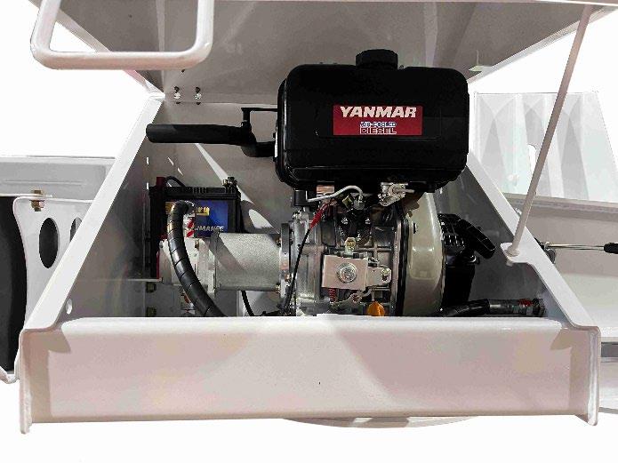
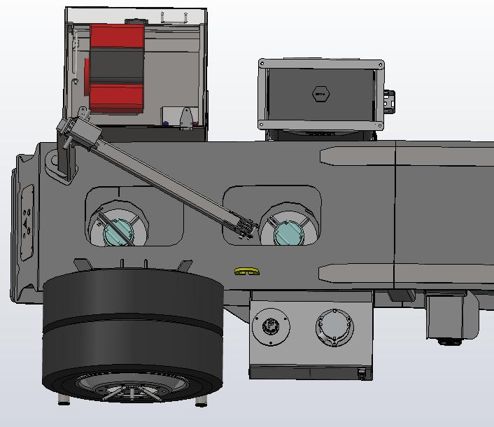
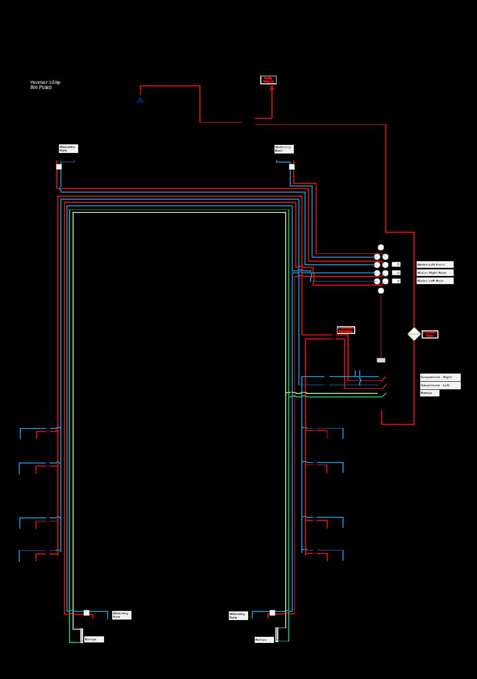
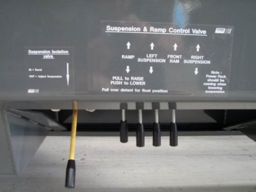
This trailer has a 10hp Yanmar diesel fitted to the Right side of the Goose-neck that supplies oil for the hydraulic functions of the trailer, and widening dolly
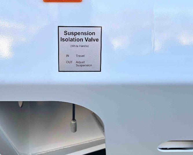
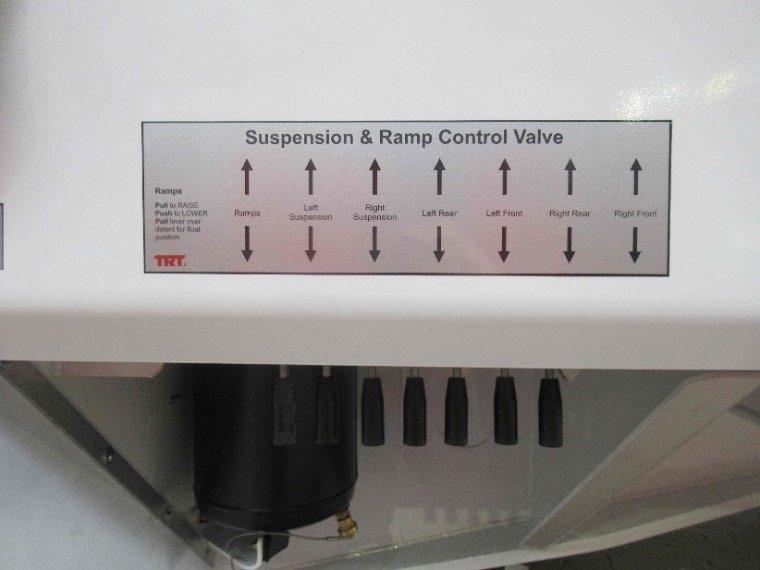
A suspension isolation valve is located near the suspension control valve on the RIGHT side of the railer. The purpose of this valve is to isolate the load from the control valve. When the lever is in travel mode (IN) the valve is closed, and the suspension load rests on the isolation valve.
A Pressure filter is in the Deck Pontoon close to Control station. Change at 6 monthly intervals.
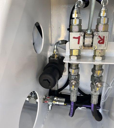
Pulling the lever OUT opens the valve and allows the suspension to be adjusted.
The hydraulic suspension in these trailers is robust and operated correctly will give many years of trouble-free use. The suspension is designed to travel about the mid-stroke of the ram to give maximum compensation for terrain conditions.
• The suspension has double acting rams and can therefore be driven up or down depending on the required ride height. Set this to suit the terrain allowing for axle movement.
• All axles have the capability of being locked in position. It is important to note that when in the lock position, the axle will not compensate with the other axles carrying the load. Do not lock axles off when there is a possibility that the axle rating will be exceeded.
Every axle line has a suspension lock valve on both sides of the trailer. The left lock valve locks the left side
• To raise an axle set – lower the trailer to the lowest position, set the valves on the left hand and right-hand corresponding suspensions in the lock position, and then raise the trailer to the ride height. The locked axles will remain in the raised position until the valve is unlocked. Do not unlock the axles when raised, as these will drop suddenly and damage the components. Also, trailer may tilt and become unstable.
• Only have the suspension fully raised or fully lowered when the trailer is stationary.
• Be aware that when raising and lowering the suspension that there is slight rearward and forward movement respectively of the trailer.
• Never raise or lower the trailer while resting on landing legs as these may collapse.
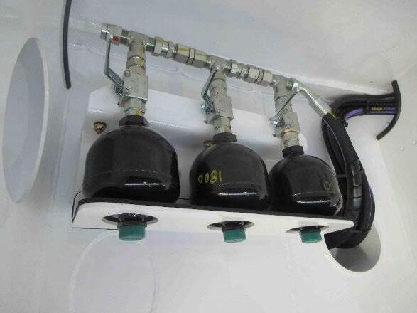
The suspension accumulators are fitted on each side of the trailer, inside the chassis rails and near the forward of the 1st axle


The trailers hydraulic suspension circuits are fitted with accumulators, which store hydraulic energy.
You MUST ensure that the pressure in the suspension lines & cylinders has been released prior to working on the circuits.
This can be done by turning the tap off to isolate the accumulators, isolating the suspension rams that are not being worked on at the axle lock valves, then manipulating the control valve handles (powerpack NOT running) to deplete any residual pressure.
Accumulator Pre-charge pressures:
Suspension
2 accumulators are charged to 70bar (1000psi) per side
1 accumulator are charged to 125bar (1800psi) Per side
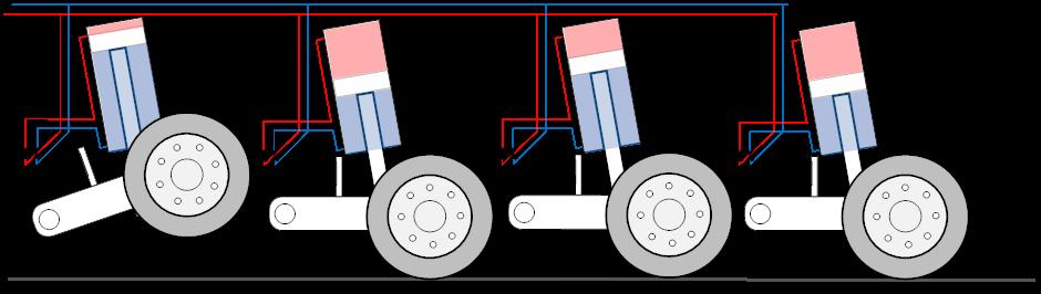
Suspension Ride Height Examples (Common for 3 to 5 axle trailers)
Ride height CORRECT
Oil is able to transfer from ram to ram as suspension ‘walks’ over rough terrain. If a wheel runs over a hump the oil will ‘pump’ from that ram into the other rams that are able to accept the volume of oil


Suspension Ride-height too LOW
The oil cannot transfer from ram to ram as there is no stroke left in the rams that the oil is trying to transfer FROM.


In this example all the load is taken on the front axle, the other sets are carrying no load.
The trailer can break its back in this loading condition
Ride-heigh too High
Oil is able to transfer from ram to ram as suspension ‘walks’ over rough terrain. If a wheel runs over a hump the oil will be unable to ‘pump’ from that ram into the other rams that are too full to be able to accept the volume of oil


This trailer can travel with an axle line raised when empty or when the load does not overload the axles remaining on the ground.
Lower the trailer all the way to the ground, Lock off the axle (group or line) that has been nominated to be carried.
When the axle is locked, raising the trailer to ride height will lift the locked axle with the trailer.


The remaining axles must be all unlocked to allow the railer suspension to ‘load share’ correctly
The operator needs to check with Local Authorities prior to operating on public roads with axles lifted
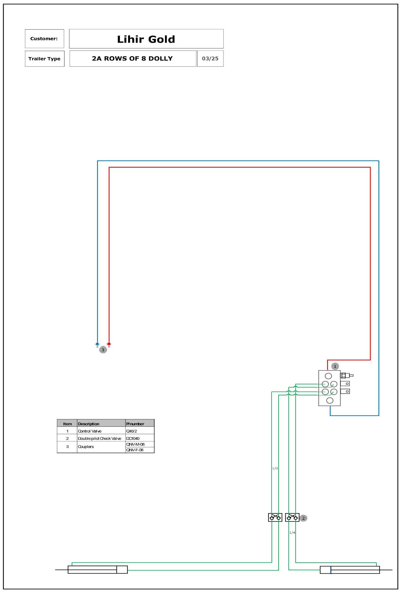
The trailer can be widened to any required width between 3.3m (fully closed) and 4.64m (fully open).
The widening cylinders are hydraulically locked by ‘Double Pilot Check’ valves.
Never attempt to adjust the width with the trailer loaded!
• Release any bindings across the trailer that may be holding down dunnage etc.
• Start the power pack
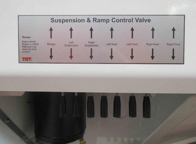
• Operate levers at the control valve to adjust the width.
The trailer can be widened 1 side at a time, or both sides together. Each widening ram has a control lever. PULL or PUSH the levers at the same rate to widen the trailer. Keep the decks parallel while widening the trailer.
• Check the width at the front and rear, and fine tune the width till front and rear are at the same measurements
• Observe the position of the rear widening ‘box’, If the centre section is not (roughly) in the middle, move it across by operating the control levers. (Pulling the lever that controls left rear widening, and pushing the right at the same time, will cause the box to move towards the left side of the trailer.)
• Place Hydraulics in travel mode

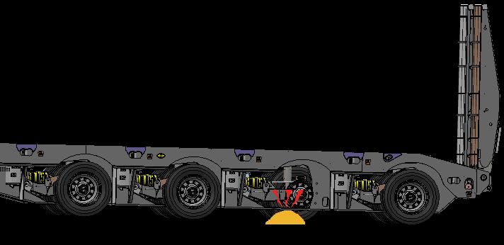
Caution: When lowering the chassis ensure the area under the chassis rails is clear of objects that may cause ‘point loading’
Ensure that the trailer is on a flat even surface and there is at least 10 metres of clear space behind the trailer for loading when using the ramps. The surface behind the transporter should not be lower than the transporter wheels or you may damage the ramps.
• Place the trailer brakes in the parked position and start the powerpack
• Place dunnage under chassis rails (see note below.)
• Lower the trailer suspension down onto the axle stops using the suspension control levers
• Release ramp restraints.
• Go to the ramp control valve and operate lever in the down position to power the ramps down. When they are on the ground PULL the ramp lever UP passed the up position and over the detented FLOAT POSITION (The ramps will rise slightly than fall back down)
• Load the equipment onto transporter and secure
• Go to ramp control valve and operate lever to raise ramps
• Place the control valve in the central position IE: NOT detented!! (Important).
• Replace the ramp restraints and secure.
• Raise the suspension to travel position.
NOTE: Always lower suspension before deploying ramps, otherwise damage to the ramp Hydraulic rams could occur.
NOTE: It is important to place adequate dunnage (approx. 150mm high) under the rear chassis rail flanges when loading cargos o f 60t or more, to prevent damage to the ramps.
The ramps can be laid down if loads interfere with ramps when they are fully raised.
1. Start with the ramps fully RAISED, the ramps secured with the retaining straps and the ramp lock valves CLOSED
2. Release the chain that actuates the tip on 1 of the ramps.
3. Locate the tip locks and fit the tip locks in place so that they will not deploy as the ramps are lowered
4. Open the ball valve on the ramp that is being lowered first and release it restraining strap
5. Start the power pack and lower the 1 ramp until it is horizontal. Stop lowering the ramp and close the ramp ram valve.
6. Repeat the procedure for the 2nd ramp.
7. With the ramps locked the taillights are hidden. A 7pin plug has been fitted to the ramp tips for a light bar to be fitted at the rearmost point of the trailer or load
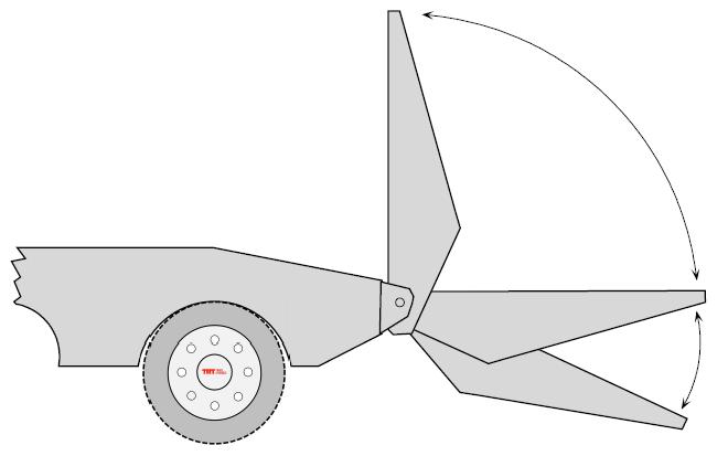
Lock rams anywhere in this arc
Prior to loading you must understand the characteristics of the machine that is to be transported. If loading this yourself, you must have the relevant license or required expertise.
• Evaluate the following prior to loading:
- Machine weight
- Centre of gravity
- Width required to safely accommodate the track width with reference to the road conditions, terrain and stability.
- Final load position to comply with axle weights.
- Traction when loading over the ramps/beavertail. A winch may be required to load safely.
• Ensure that the transporter is on flat even ground and that you have sufficient space behind the transporter to load in a straight line. The loading operation must be protected from other traffic.
• It is important that the area under the bottom flanges, at the wheel cut-out areas, is free
• Apply the truck and trailer brakes.
• Lower the trailer suspension. Make sure the power pack running. Do not lock off individual axles or damage may occur.
When the ramps are carried horizontally, they should be also tied to the load to minimize stress on the ram and its mounts
• Remove the ramp securing chains and lower the ramps ensuring that no personnel or equipment are in the way (push lever to lower ramps, pull lever to raise ramps, and pull over detent for float position). Leave ramp control in the detented position when loading or damage to ramp rams will occur. The ramps must be in full contact with the ground and bear evenly on each side of the transporter.
• When loading. The ramp valve must remain in the float position.
• Dunnage should be placed under rear of the chassis for loads over 60t
Place dunnage under pontoon spine flange end
The 2” Kingpin is a Drop-in type of kingpin and can be located in the forward (dolly) position or rear (truck position.)
• Load the machine according to manufacturer’s instructions. Care is to be taken at the apex of the beavertail, as the machine may become unstable. It may be necessary to use a winch to assist the loading at this stage. Position the machine to give the permitted axle loading.
• Secure the load as required by the Restraint of Load Regulations.
• Raise the ramps to the vertical position ensuring that they are clear of the load. The valve must remain in the mid-position once the operation is complete.
• Secure the ramp restraints. Do not overtighten.
• Raise the suspension until deck is at ride height.
• Check that the tyres are adequately inflated.
NOTE: To lower the Ramps, the control lever must be pushed Inwards, to float push down past the detent
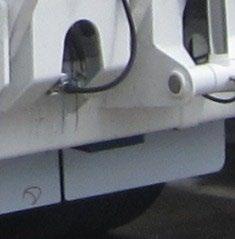
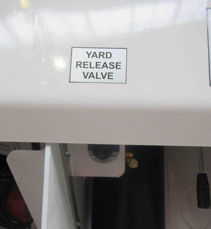
TRT trailers are fitted with a yard release valve. This valve allows the brakes to be released (IF there is sufficient air in the trailers air reservoirs) without a truck attached. The purpose of this valve is to easily facilitate the moving of the trailer in a yard area or workshop without the requirement of a vehicle set-up for air brakes.
CAUTION: When activating the yard release valve restrain the trailer from ‘running away’
The yard release valve automatically resets itself to normal operation when an air supply is coupled to the trailer. It is located near the hydraulic control station
• PUSH to release brakes
• Pull to re-apply brakes
(Valve re-sets to normal brake operation when trailer is coupled to truck air supply)
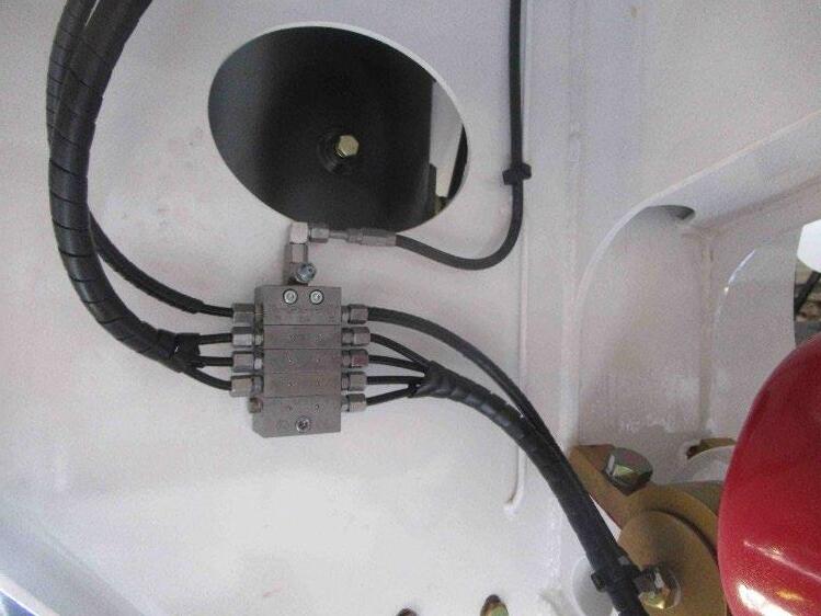
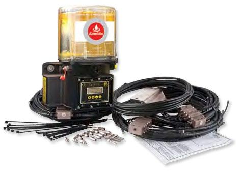
The manifold greasing option uses Alemlube grease manifolds which are manually greased at their inlet grease nipples. For servicing the grease blocks if they leak or develop a blockage, please see the grease manifold manual at the back of this manual
MAINTENANCE AND SERVICE
MAINTENANCE SCHEDULE
VISUAL CHECK FOR DAMAGE
VISUAL CHECK TYRES FOR WEAR AND INFLATION
CHECK FOR HYDRAULIC AND AIR LEAKS
CHECK / REFILL AUTO-GREASER
CHECK TIRE PRESSURES
CHECK WHEEL NUT TORQUE
CHECK / ADJUST BRAKES
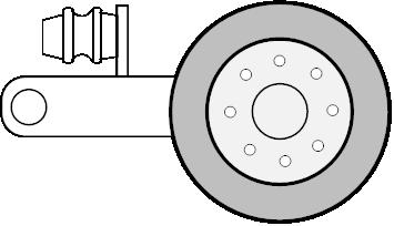
GREASE SKIDPLATE
CHECK WHEEL BEARINGS
CHECK BRAKE SHOE WEAR
CHECK S-CAM BUSHES
CHECK BRAKE DRUM WEAR
CHECK ACCUMULATOR PRESSURES
CHECK WHEEL BEARINGS AND RE-GREASE
BEFORE OPERATING TRAILER: King Pin must be amply greased with E.P. grease with MoS2 or graphite additive. Sufficient greasing of King Pin and fifth wheel coupling is most important for the lifetime of both components.
NOTE: WHEEL NUTS MUST BE TORQUED AFTER THE FIRST 100km. AUSTRALIAN TRAILERS MUST HAVE THE WHEEL NUTS TORQUED BEFORE LEAVING THE PORT.
COMPONENTS’
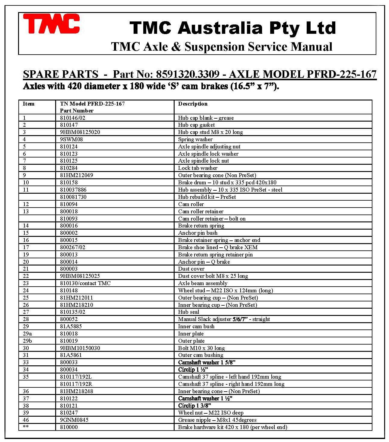
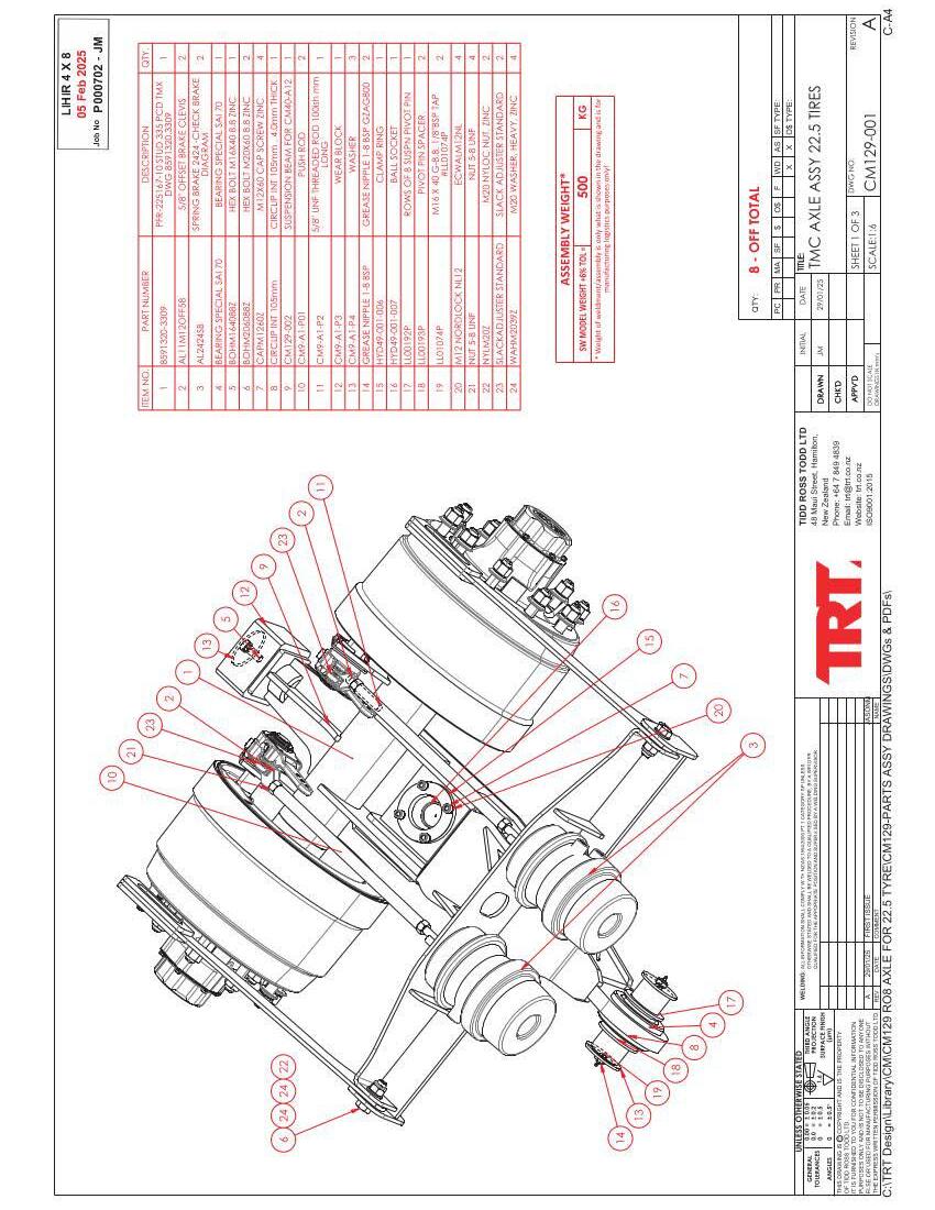
Axles
PART NUMBER
TMC 10 Stud TM8591320.3309
Suspension TRT Hydraulic
Wheels
OGR 370 (Alloy)
Wheels OGR205 (Steel)
Tires
King Pin
Kingpin
Frampton joint kit
Suspension ram rod ball
Suspension ram rod ball SOCKET
Suspension Guide Block
Suspension Pivot Bearing Kit
Suspension Pivot pin
Suspension Pivot Shim kit
Suspension Pivot Spacer kit
Push Pad
275 70r 22.5
TDKP0406004 3.5” Drop-in
TDKP0406005 2” Drop-in
TDHYD17-A3RK
TDHYD49-001-003B
TDHYD49-001-007B
TDCN9-A1-P3
TDPBK-SAI70
TDLL00192P
TDPSK-P8
TDLL00193K
535-05-040
Motor Yanmar L100N6METM
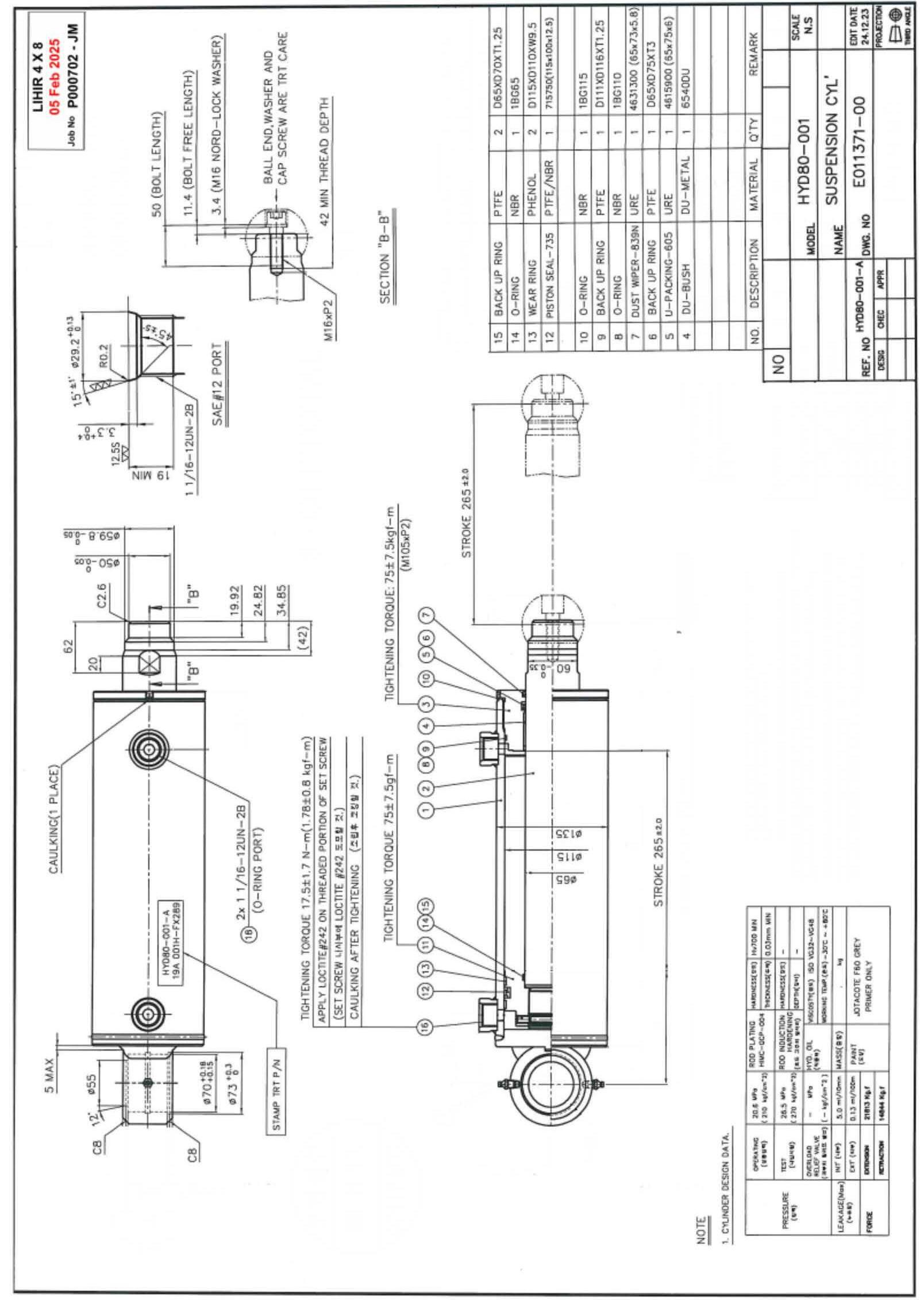
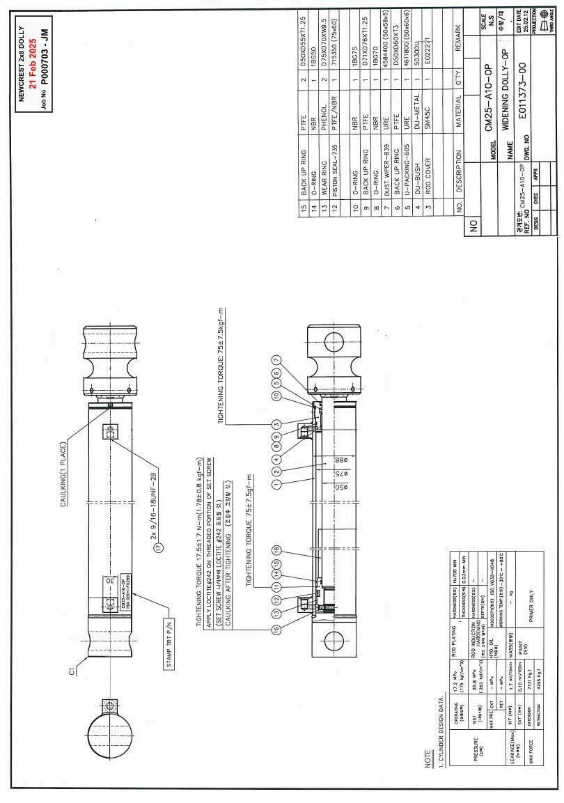
Widening Rams
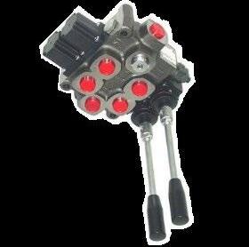
Suspension Rams
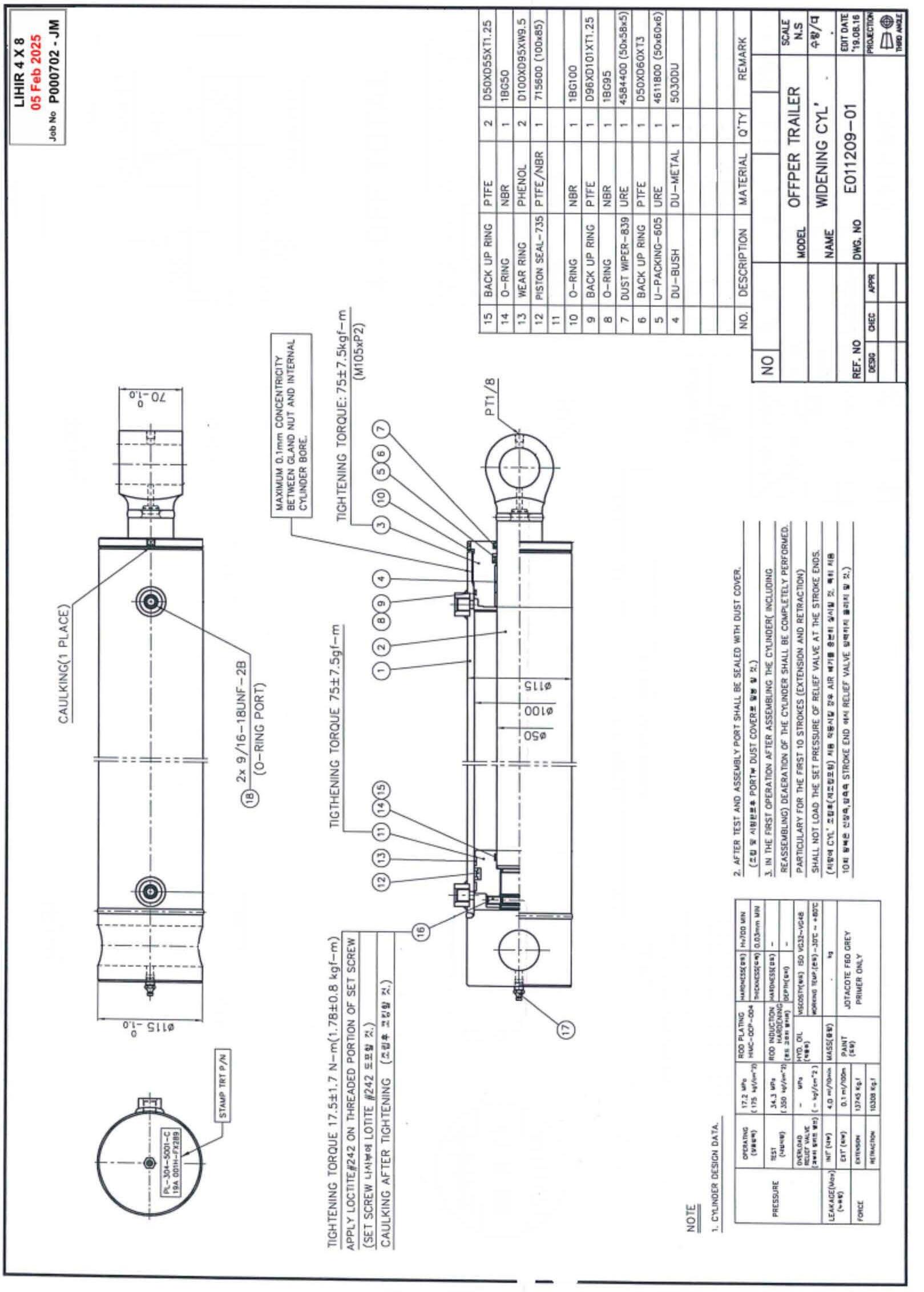
Ramp Rams
Pressure Filter element
Control Valves 6 Spool
Detent Kit
Double Pilot Check Block
Double Pilot Check Cartridge
Hoses & Fittings
Accumulator 1litre
Lock Valve Assembly
Lock Valve Handle
Battery
304-5001
TDHYD80-001
TDRM27-A21-C-HIMC 4” x 2” x 16
CHP281F10XN
Q45 M/6 (see Build Sheet)
HY03750R10/Z1
HS 1040 P6-2
DC 10-40
HYDRAULINK
AMELM1200AFG14
TDLVASS
AMDCV40-H
EX40CMF
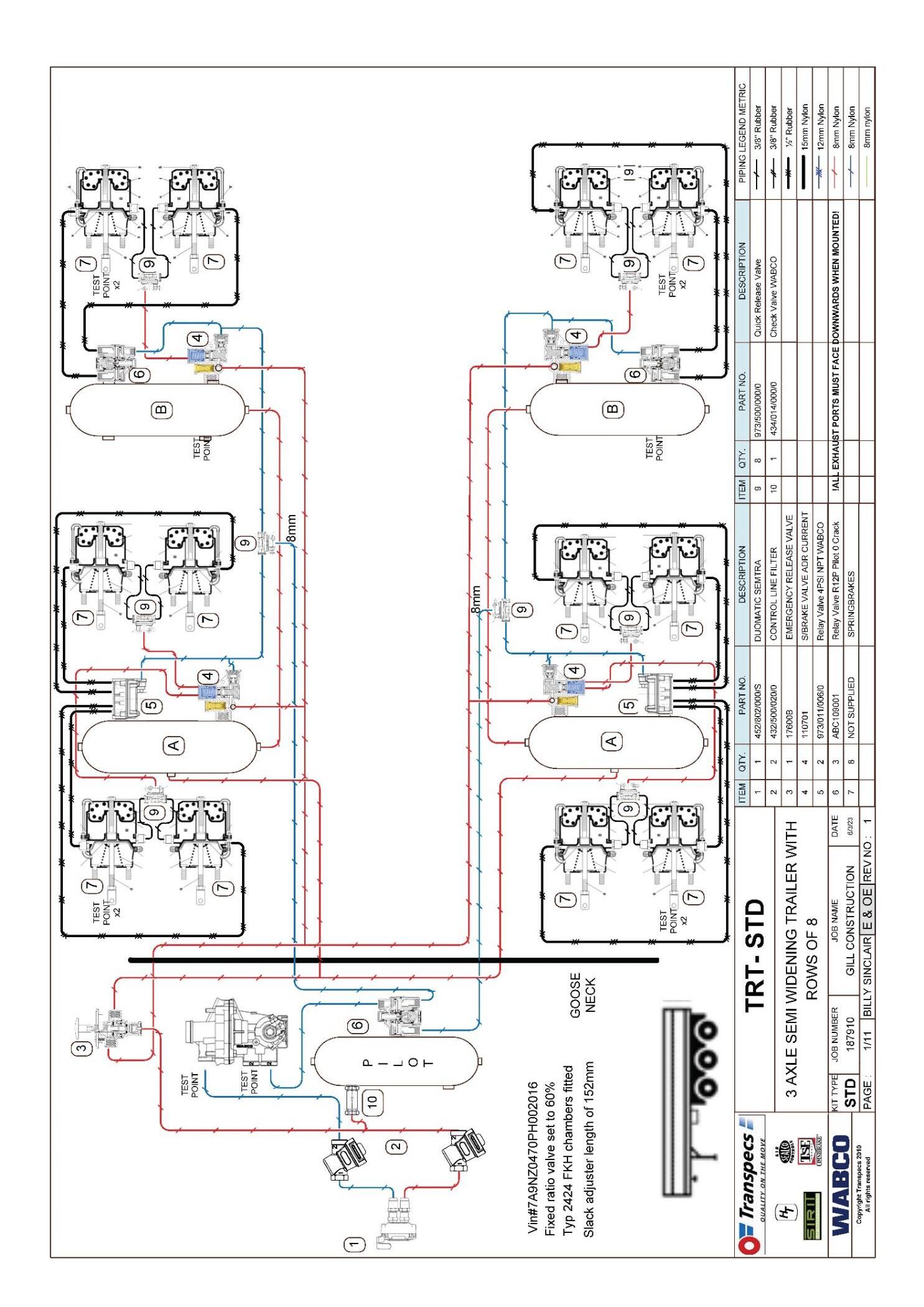
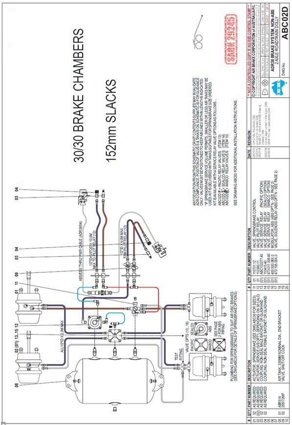
SPRING BRAKE 24/24
SLACK ADJUSTER
PILOT RELAY VALVE
SERVICE RELAY VALVE
SPRING BRAKE VALVE
FIXED RATIO VALVE
YARD RELEASE
CHECK VALVE
QUICK RELEASE VALVE
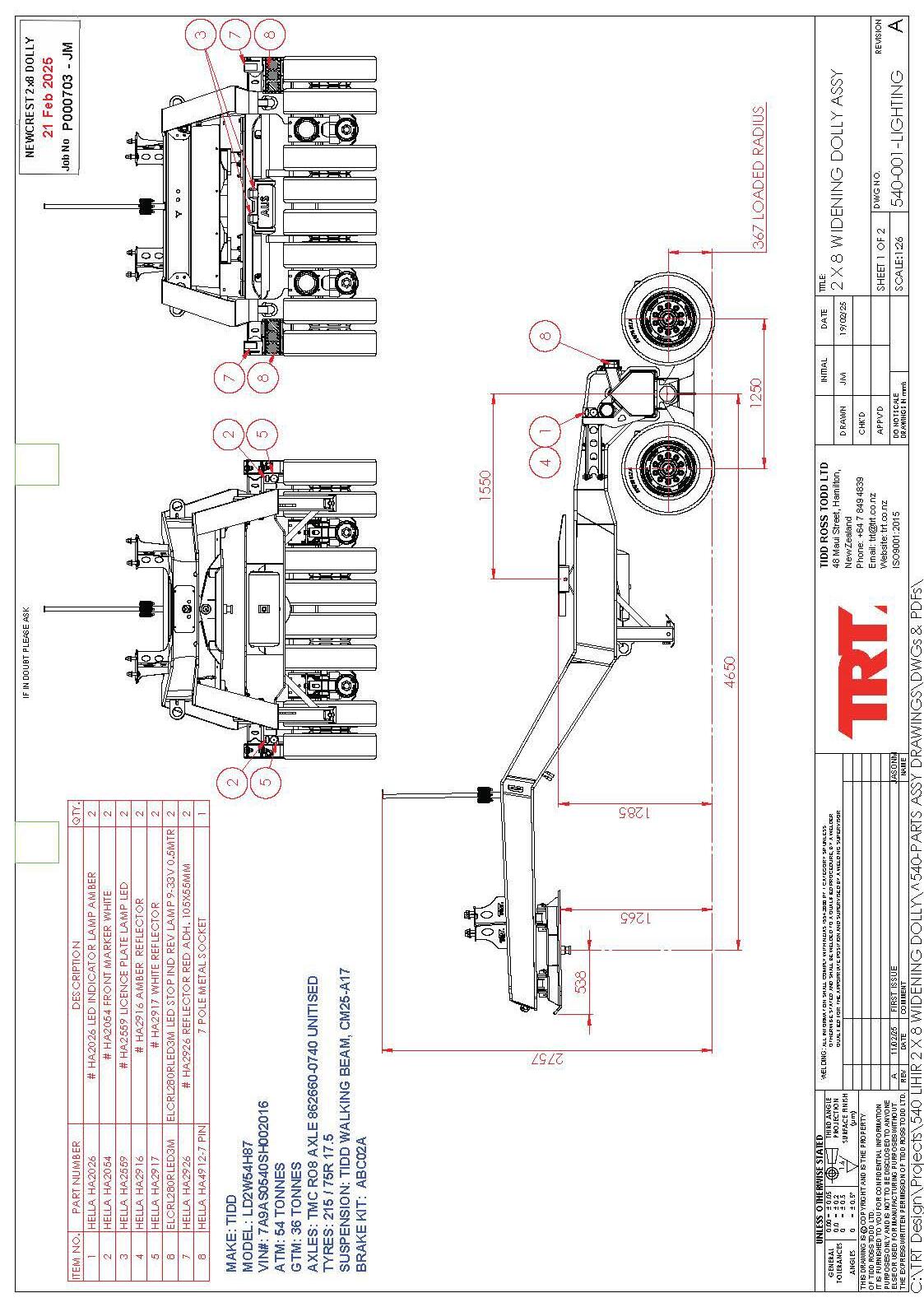
LIGHTS LED COMBO STOP, TAIL, INDICATOR
SIDE MARKER LAMP AMBER LED
SIDE / END RED LED
LICENSE PLATE LAMP LED
SIDE INDICATOR
REFLECTORS CLEAR
REFLECTOR RED
WORKLIGHT
BEACON (ROTATING - LED)
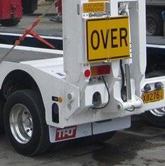
SIGN - OVERSIZE
SIGN
RW2424SB
BW0539726030
ABC109001
973/001/006/0
SL110701
475/713/60
SL17600B
434/014/000/0
WA9735000000
HA2053
HA2309
HA2559
HA2031
HA2921
HA2926
AMTDRO8201
BCN01A
AMSIGNOS
AMSIGNBHAZPLH AMSIGNBHAZPR/H
Torque Settings
Reliefs set at 195bar 2800psi


Detent position

NOTES:

Please write spool type on Valve turret to identify valve spool (Twink or paint pen)
(Use this sheet when ordering a replacement valve)
Suspension Ram
Backing Plate

Ball Valve (x2) (Hydraulink BV-08)


Limit plate & limit pin

valve handle

Over the course of time the Lock Valve mechanism can fail due to wear in the drive ‘biscuit’ or a valve seizing.
Valve function checks if failure is suspected
• Make trailer safe by lowering onto dunnage, then turn the power pack off and manipulate control handles to deplete any residual pressure in the suspension lines.
• Remove the hoses from 1 end of the lock valve and, with the valve in the open position, attempt to pass a (clean) rod through the valve. (It should pass through both sides of the valve)
• Repeat the above test with the valve in the closed position
• If failure is proven remove and strip the valve for repair.
Reassembly notes
• Check that BOTH valves open and close and are not in any way seized or seizing.
• Start assembly with both valves in the open position
• Carefully position the limit plates to allow the valve to operate through it required motion.
• inspect the drive biscuit for wear in the square and the handle thread, replace it required.
• Reassemble and check its operation before fitting to trailer.
• Check that the valve operates correctly to the instruction decals
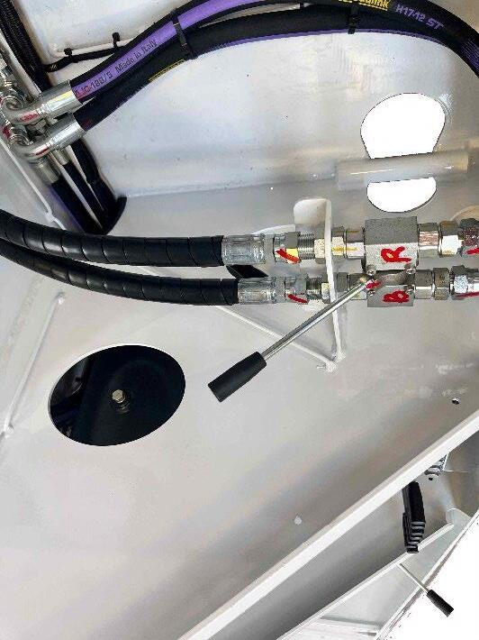
To check operation of Lock Valves and Suspension Isolation valve:
1. Ensure trailer is supported on dunnage under the chassis rails
2. Release all line pressure in suspension lines by operating suspension control levers up and down with power pack OFF Suspension lock valves open and Suspension Isolation valve in the Adjust Suspension position)
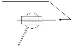
3. Remove the hoses from one end of lock valve
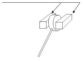
4. Try to pass a (clean) welding rod, wire etc. through Valves. If it passes through 1 but not the other in the pair, they are out of ‘phase’ (often caused by the ‘biscuit between the valves rounding off the drive square due to a seizing ball valve)
5. If the valve is out of phase it will need to be removed, dismantled and corrected. (Drive biscuit replaced if worn and ball valve un-seized or replaced) Remove the 4 bolts through the backing plate and separate the ball valves from the drive biscuit. Observe and orientate both ball valves to the open position, refit the ‘stop washers’ in the correct position to allow handle movement, and refit the valves to the drive biscuit. Refit the backing plate and test for operation before refitting to trailer


NOTE: When reassembling the unit, make sure the handle is in the correct position for open and closed according to the decals on the trailer.
1. Raise the Trailer to full height
2. Lock off all Suspension lock valves. OPEN 1 suspension lock valve for ram to be tested.


3. Remove the BASE hose from the ram side of this lock valve fitting, (A little pressure may be evident) and CAP THE LOCK VALVE FITTING
4. Fit a PLUG to the BASE HOSE but leave it quite loose.
5. Start the power pack up (suspension isolation valve in Adjust suspension position) and raise the wheel off the ground to about 1/3 the stroke of the ram. (Oil will be pushed out the loose plug)
Test 1:
Stop the power-pack, return the suspension isolation valve to the travel mode, and observe the ram spear.
If the ram extends under the weight of the wheels and axle the seals are damaged
Test 2:
If the ram passes on test 1, tighten the plug on the BASE hose to stop any further oil escaping. Restart the power pack and Open the Suspension isolation valve. For the side of the trailer being tested, push the suspension control lever DOWN and hold it in this position while observing the suspension ram. The ram will attempt to lift the wheels further off the ground but will be unable to due to the base hose being capped.


Test 2 Cont’d:
Expect the ram to close a little, but if it then starts to EXTEND the seals are damaged

NOTE: Repeat tests 1 and 2 at ½ and ¾ stroke positions on the ram, as a ‘bulged’ or ‘scored’ ram can produce the same symptoms.
Oil is forced into the spear end of the ram and attempts to push the piston upwards; this movement is resisted by the capped hose on the port at the base of the cylinder preventing oil above the piston from escaping.
1. If the piston seals are serviceable the piston will stall, and the oil will be forced over the relief setting at the control valve.


2. If the piston seals are damaged the oil will bypass the seals and cause the rod to SLOWLY extend from the ram. This happens because the base end of the piston has a greater surface area than the surface area of the spear end. When the same pressure is exerted on the two unequal areas, a greater force is present on the larger face, causing the ram to extend.
In the event of 1 (or more) ram(s) in a suspension side having damaged seals the side effected will be slower to operate (or may fail to lift the trailer) due to the bypassing oil. When all suspension lock valves are open, but the Isolation valve is closed the oil will slowly equalize both sides of ALL the cylinders on that side of the trailer, but the trailer will ‘Droop’ on the side affected.

Check accumulator pre-charge pressure every 3 months or when in doubt regarding its operation.
See instructions below:
Read instructions through completely before you start to familiarise yourself with the procedure.
• Lock suspension valves and power-pack turned off
• Move suspension levers up and down a couple of times to release any residual pressure.
Note:
If the trailer is fitted with counterbalance valves in the suspension lines, there will still be residual pressure in the suspension circuit. Proceed carefully realising that each accumulator may contain oil.
• Close accumulator isolation valves on the side of the trailer you are working on
• Loosen suspension hose from 1 accumulator (quite loose but not removed)
• SLOWLY open the accumulator isolation valve (be prepared to contain any spillage)
• when isolation valve is fully open remove hose completely from fitting
• Set up test kit as per drawing
(Accumulator manufacturer: STAUFF, most hydraulic service agents should have a universal charging kit)
• Accumulator isolation valve must be OPEN
• Check that Bleed Screw is open, and Valve Actuator is wound back
Assemble charging unit as per drawing shown on next page
Hydraulic Isolation Valve this end


Gauge

Accumulator
Bleed screw


Valve Actuator

Gooseneck 135 bar
Suspension 70bar (2 of per side)
Suspension 125bar (2 of per side

Nitrogen Bottle
• Purge hose from bottle by opening bottle valve slowly and slightly allowing Nitrogen to bleed out for 3 to 5 seconds
• Close bleed screw
• Close bottle Valve
• Open bleed screw to drain line till gauge reads 0 psi.
• Close bleed screw
Note: Don’t wind valve actuator handle in too hard or it will damage the valve core
Note: If oil is present at the “gas end” of the accumulator it is unserviceable
• Wind in valve actuator till gauge shows pressure (or actuator bottoms out) Gauge now shows pre-charge pressure
• Open bottle valve slowly and slightly allowing nitrogen to flow into the accumulator for 5 to 10 seconds then close bottle valve
• Observe pressure gauge
• Continue slowly charging accumulator till it is slightly over the required pressure
Bleed the pressure down to the required pressure
• Back off “Valve Actuator” Handle
• Bleed off the line pressure from the bottle
• Disassemble charge unit and return to its case
• Check the Accumulator valve is not leaking and refit cap

TORQUE VALUES in Nm for ft/lb multiply by .74
All bolts must be coated with rescue steel or loctite
M14 - 190Nm
M16 -
M20 - 500Nm
Brake Chambers - 190Nm Wheel Nut (M22 x 1.5) - 600Nm
M18
M20
ALL Brake Chambers must have Nyloc Nuts and Hardened Washers
VIN 7A9NZ0526SH002003
TARE 4460KG
GVM 45,000Kg
AXLE BRAND TMC TYPE 10 STUD
AXLE SPACING 1232MM
SUSPENSION TRT WALKING BEAM
WHEELS
17.5 X 6.0
TYRES 215 75R 17.5
KINGPIN 3.5”
5TH WHEEL JOST JSK38G (3.5” jaws)
WIDTH 2773mm
AXLE SPACING 1250mm
DOLLY SAFETY INFORMATION
BEFORE OPERATING TRAILER: King Pin must be amply greased with E.P. grease with MoS2 or graphite additive. Sufficient greasing of King Pin and fifth wheel coupling is most important for the lifetime of both components.
NOTE:
WHEEL NUTS MUST BE TORQUED AFTER THE FIRST 100km.
AUSTRALIAN TRAILERS MUST HAVE THE WHEEL NUTS TORQUED BEFORE LEAVING THE PORT.

Major components of this trailer are made from GRADE
80 High Tensile steel, PREHEATING BEFORE WELDING is essential to avoid post welding cracking.
Please contact TRT for welding procedures and consumable specifications before welding.
TRT NEW ZEALAND
07 849 4839
trt.co.nz
48 Maui Street
Pukete
Hamilton
Failure to contact TRT to gain the proper weld procedure could cause additional failures and may result in the warranty being voided.
DOLLY PARTS LIST
COMPONENTS
AXLES
TMC862660-0740
SUSPENSION TIDD CM25-A17
BRAKE KIT TRANSPECS
SLACK ADJUSTER TMC (15mm OFFSET - L and R)
BRAKE CHAMBERS AM3030SB
WHEELS
WHEELS
TYRES
OGA370 (ALLOY) OGREEN
OGR205 (STEEL) OGREEN
5TH WHEEL JOST 38G
LIGHTS LED (SEE Pg 4)
CONTROL VALVE GALTECH Q45 M/2 (Motor spools)
PILOT CHECK VALVES
DC10-40 (Cartridge numb CM25-A10-0P
Operating instructions
The outfit should be parked on a flat and even road surface.
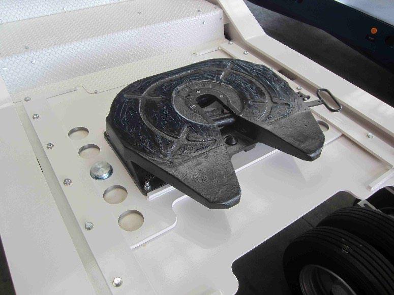
Coupling-up:
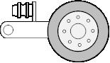
1. The fifth wheel must be in the reset position, i.e. the end of the operating handle standing out approx. 300mm, otherwise: Remove spring clip (A) and move handle forward to unlock (B). Pull handle to end position (C).
2. Skid plate of semi-trailer should be approx. 50mm lower than the top of the fifth wheel.
IMPORTANT:
Loss of pressure in the air suspension of the trailer can alter the height of the king pin.
3. Reverse tractor - the mechanism locks automatically.
4. Check that the skid plate is resting on the fifth wheel plate with no gap between the two.
5. Insert spring clip in the eye on the fifth wheel plate (A).
IMPORTANT:
Insertion of the spring clip indicates that the locking mechanism is closed. If it is not possible to insert the spring clip, the coupling-up procedure must be repeated.
Uncoupling:
1. Remove spring clip (A). Move handle forward to unlock (B). Pull handle to end position (C).
2. Drive tractor away. The fifth wheel mechanism will automatically assume the coupling-up position (D).
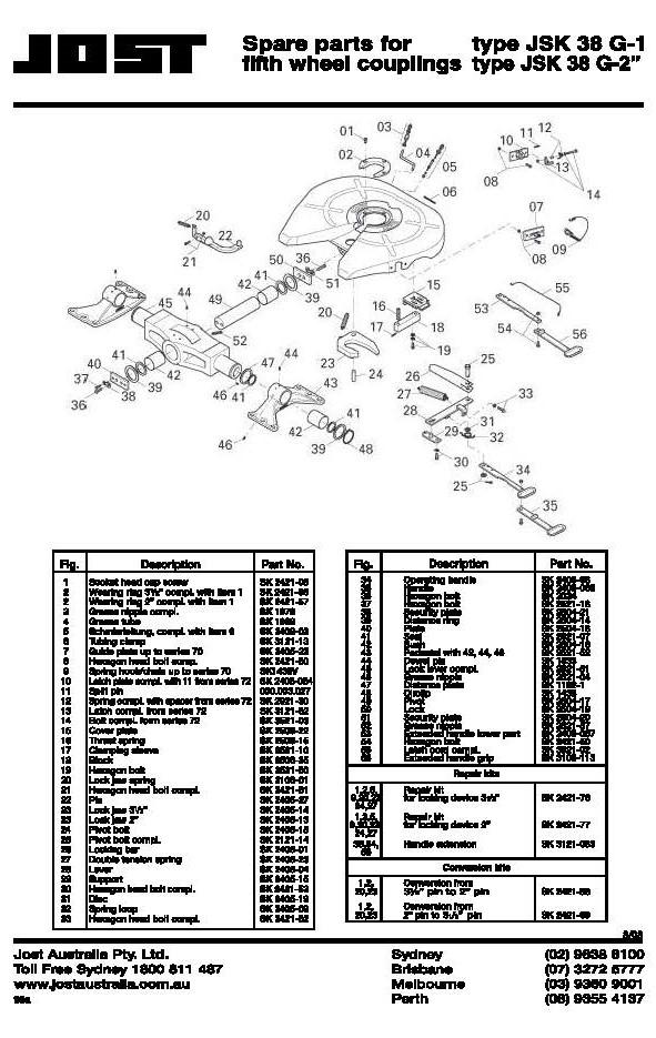
Lateral movement on type JSK 38 G and JSK 38 G-1
The lateral movement should only be released for off-road use. On the road, and especially at higher speeds, it must be blocked for safety reasons.
To set the lateral movement:
For normal road use: Lateral movement released
1. Release the hex. bolts (2 each side - width over flats 19mm).
2. Push both blocks in to the end of the oblong hole.
3. Re-tighten hex. bolts (torque 80 Nm).
For off-road use:
1. Release the hex. bolts (2 each side –width over flats 19mm).
2. Pull both blocks out to the end of the oblong hole. Lateral movement blocked
3. Re-tighten the hex. bolts (torque 80 Nm
The 5th wheel on the dolly can pe moved to any one of 3 pinning positions.
The pinning of the slider will determine how much weight is transferred from the front of the trailer through the load sharing dolly suspension, to the drive axles of the truck
1. Sliding the 5th wheel forward or back is best done with an empty trailer. If this is not possible the trailer needs to be set up with
a. The skid-plate level
b. The gooseneck supported under the centre.
c. When the gooseneck is supported the skid plate needs lifting a little to take the weight off the dolly slider
2. The Truck and Dolly need to be attached, and the air supply connected to the dolly.
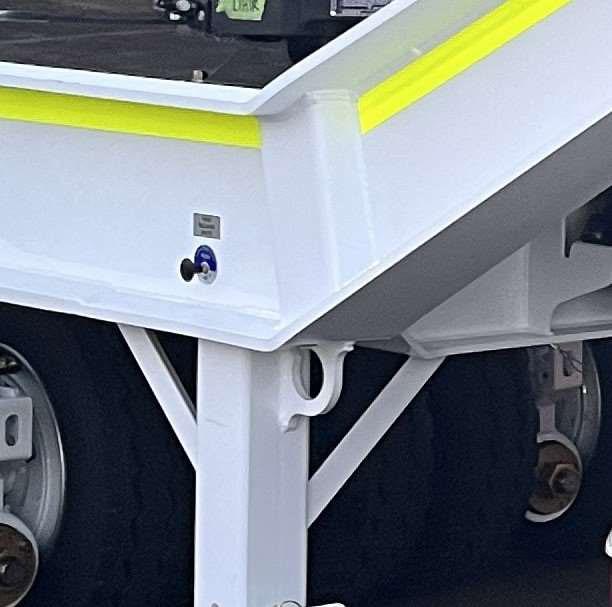
3. Remove the air supply from the dolly to the trailer to lick the trailer brakes on while the dolly brakes are released.
4. Operate the air toggle on the Right side of the dolly to lower the locking pins. If they don’t lower the truck may need to ‘bump’ the dolly forward or back to release the pins.
5. When they are released, drive the truck slowly to the required pinning position and re-apply the pins.
6. Check that both pins have fully engaged.
1 . Uncouple semi-trailer at least once a week, certainly after more than 5000 km. Clean semi-trailer skid plate and fifth wheel plate. Lubricate fifth wheel plate, locking mechanism, fifth wheel throat and king pin, with heavy duty grease. We recommend the use of high-pressure grease (EP) with MOS2 or graphite additive, for example: BP L21 M, BP HTEP 1, BP LS 2, Esso universal grease M, Shell Retinax AM. Check operating handle and release lever pivots for free movement - clean and lubricate.
2. The bearings of the lock lever (item 28) and of the pedestals of the JSK 38 G-1 and the pivot bearing of the JSK 50 are to be re-greased through grease nipples provided, at each maintenance interval. The rubber cushions of the JSK 38 C-1 are maintenance free. According to operating conditions we recommend checking parts for wear at 50 000 and 100 000km distance driven.
3. The grease nipple on the outside of the fifth wheel plate is merely to be used for lubrication inbetween service intervals.
4. The fifth wheel coupling must be checked as to its proper functioning according to operating conditions. The fifth wheel itself, the mounting plate, or the slider and the king pin including the fixing bolts must be checked for deformation or cracks. The fixing bolts should be checked as to the correct torque.
In the interest of longer working life and trouble-free-functioning, the top plate, locking mechanism, king pin and the bearings of types. JSK 38 G-1 and JSK 50 should be well greased before the initial coupling-up operation.

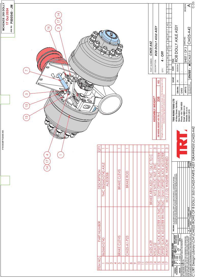
When adjusting the breaks on the dolly it is important to keep the slack adjuster as parallel as possible, and to have the braking happening when the slack adjusters are leaning slightly towards the brake chamber


NOTES:

CUSTOMER
TRAILER TYPE
REGISTRATION / FLEET No.
Chassis
Thorough check for Cracks
Bent or deformed areas
Ram pin wear
Pivot and hinges (swing arms / Ramps)
Air leaks
Kingpin Condition
Hydraulic
PTO Couplers
Powerpack function
Powerpack service
Pressure Filter
Return Filter
Flow Control Setting
Relief set pressure at…
Control valve Function
Widening Valve Function
Additional Valve function
Additional Valve relief Setting
Hydraulic hoses
Leaks
Suspension
Condition of Rims / Tyres
Condition of suspension Rams
Job Number:
Date:
Condition of suspension pins / Bushes
Air bags
Rubber Bushes
Wheel nuts Torques
Mudflaps
Brake material level (Pads / Shoes)
Brake hoses
S-cams Bushes
Slack Adjuster condition
Brake adjustment
Wheel Alignment
Wheel Bearings
Shock Absorbers and straps
Lights and Decals
Clearance Lights
Stop, Tail, Indicator lights
Beacons / Flashers
Wheel lights, Toolbox lights
Work Lights
Decals legible
Delineators, Safety signs condition
Ancillary Equipment
Autogrease system
Winch
Remote Control
Operator comments, complaints
Failure Notes