
Please contact the TRT service department if you have any questions about your trailer. Please list the model number and Vehicle Identification Number (VIN) in all correspondence.
Manufacturer
TRT - Tidd Ross Todd Ltd 48 Maui Street
Pukete Industrial Estate Hamilton 3200, New Zealand
Phone: +64 7 849 4839
Fax: +64 7 849 3628 trailers@trt.co.nz www.trt.co.nz
Contact your local distributor.
Supplied Trailer Information
Supplied documentation (electronic) comprises the following: Operating Procedure, Risk Analysis, Rated Capacity, Parts Catalogue and Service Manual.
Any modifications made to the Trailer must be approved by manufacturer. Failure to gain written approval will void warranty.
Vehicle Identification Number (VIN)
When corresponding with the manufacturer the VIN should be included, it will be used to identify the trailer. (VIN is located at the front of the trailer.)
TRT Australia 1028 Lytton Road, Murarrie, QLD 4172 Australia
Phone: +61 7 3890 8800
Email: cranesales@trtaust.com.au www.trtaustralia.com.au
4.1.10.
4.1.12.
4.1.13.
4.1.14.
4.1.15.
4.1.21.
4.1.22.
4.1.23.
4.3.
5.6.
5.7.
VIN 7A9NZ0513RH002054
Model HT3H50ABOD
Tare weight 17960kg
ATM rating 50,000kg
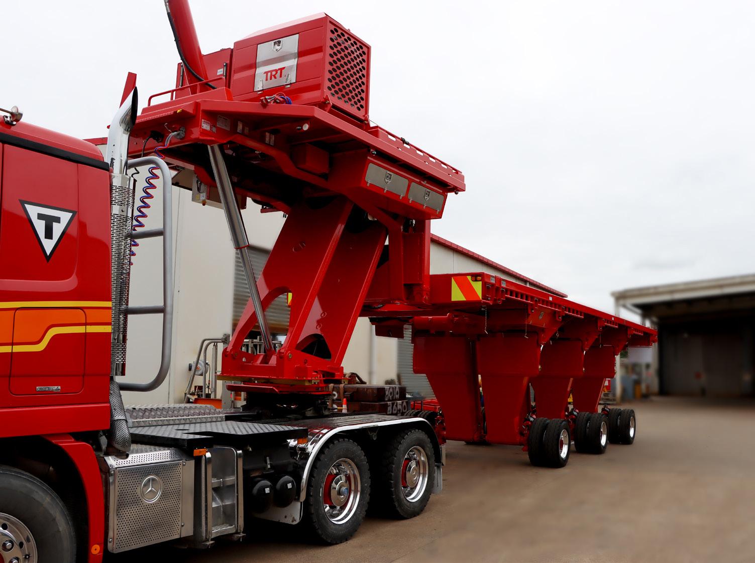
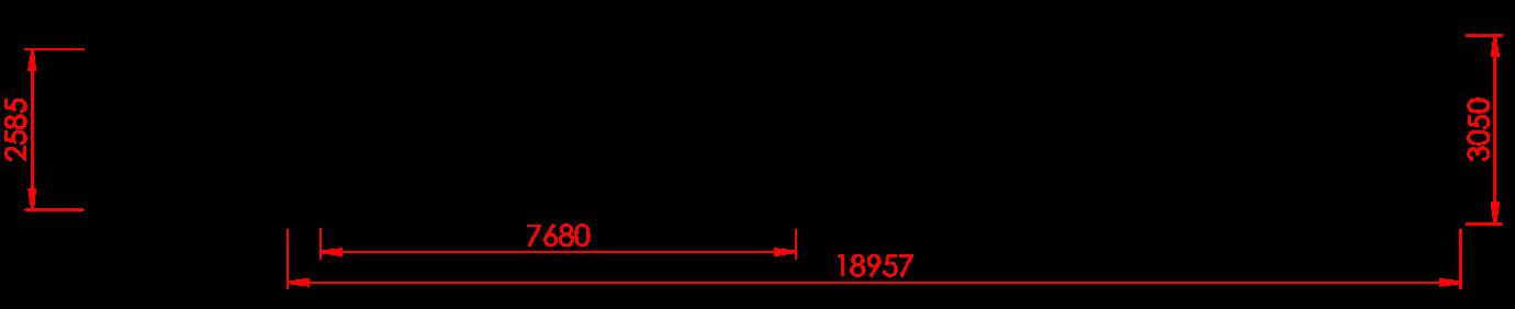
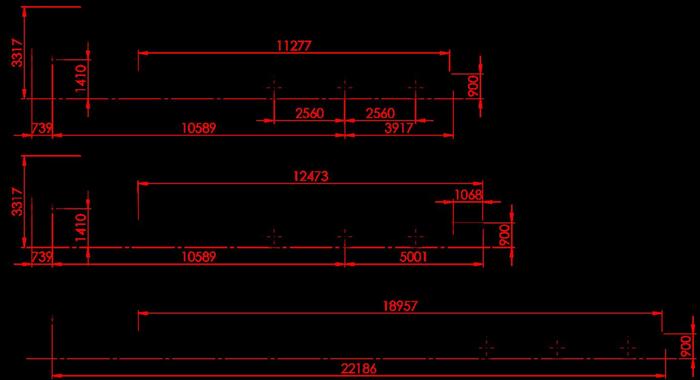
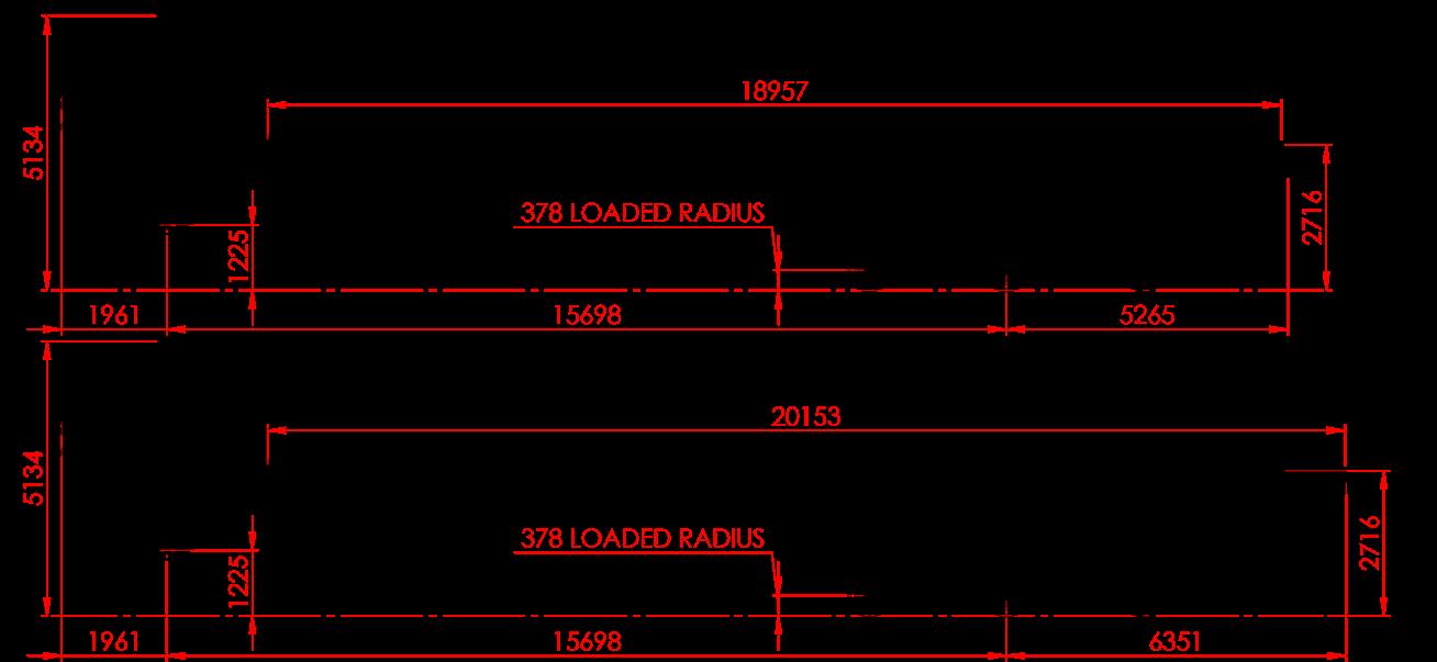
Deck length (behind gooseneck) 11,200mm (Closed) 18,900mm (Open)
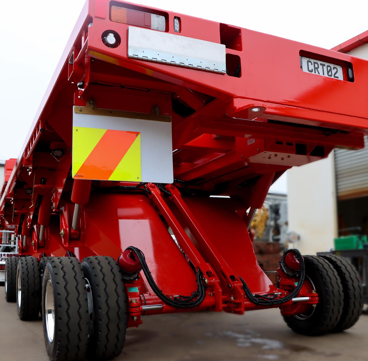
Width 3050mm
Deck height - lowered 880mm
Deck height - raised 2750mm
Axle spacing 2400mm
2.1.


2.3. Suspension Lowered
2.4. Suspension Raised
3.1. Legs
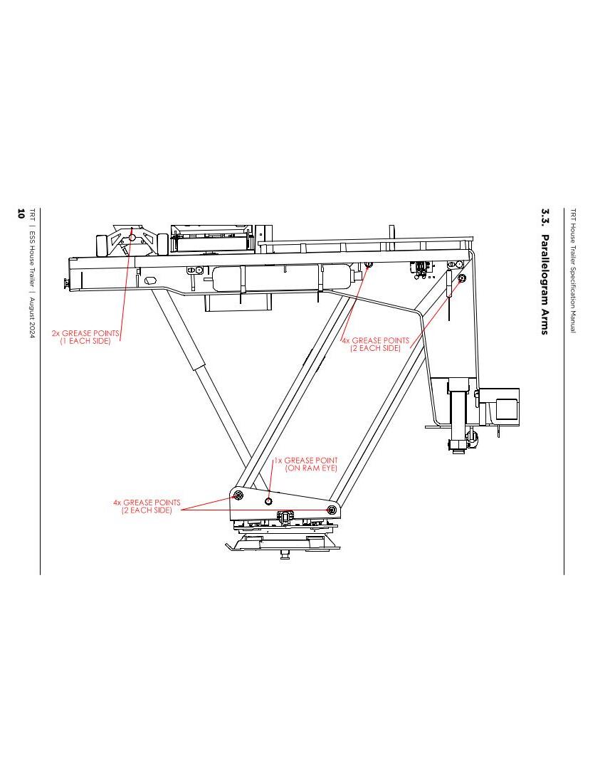
OPERATE LEGS UP AND DOWN THROUGHOUT THE GREASING PROCESS. THIS WILL ENSURE ALL COMPONENTS ARE SUFFICIENTLY LUBRICATED.
SIDES)
GREASE POINT (PIN ON BOTTOM OF RAM) 2x GREASE POINTS (1 EACH SIDE OF RAM PIVOT) GREASE POINTS 2x GREASE POINTS ON STUB AXLE PIVOT BOSS (UNDERSIDE) GREASE POINT
Grease nipple (on Ram eye @ #3)
2 grease nipple / side @#4 (total of 4) 6 grease nipples on slew ring
1 Grease nipple each @ #1 (total of 4)
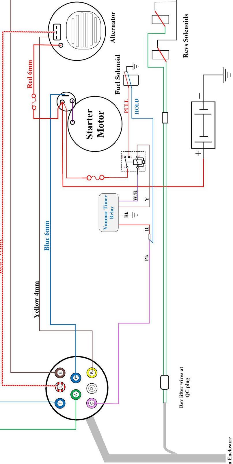
4.1. Electrical
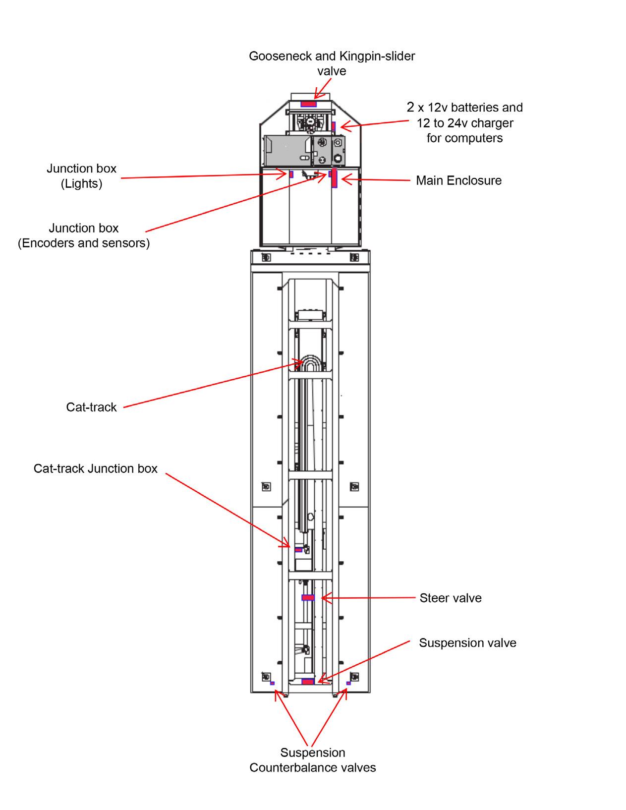
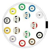
4.1.1. Trailer Plan View

NOTE: **OUT_23 is used to provide power to OUT_41 and OUT_42 only in the House Trailers.** **In Platform Trailers, OUT_23 is used for widening, and power for OUT_41 and OUT_42 are connected directly to battery voltage.***
NOTE: **OUT_23 is used to provide power to OUT_41 and OUT_42 only in the House Trailers.** **In Platform Trailers, OUT_23 is used for widening, and power for OUT_41 and OUT_42 are connected directly to battery voltage.***

A/B Signal C Signal A/B Signal 1 2 3 4 1 2 3 4
RC12-10/30 NPN Inputs
RC12-10/30 NPN Inputs GND Pins GND Pins
RC28-14/30 NPN Inputs
A/B Signal C Signal A/B Signal C Signal A/B Detect 1 C Detect 1 A/B Detect 2 C Detect 2
3-4 Axle Trailer (A&B) 1 2 3 4 1 2 3 4
RC28-14/30 NPN Inputs GND Pins GND Pins
C Signal A/B Detect 1 C Detect 1 A/B Detect 2 C Detect 2
NOTE: Detection pins are used to determine which modules are connected in the front and back of each module. This assists in cross-checking that the correct module IDs were entered by the operator in setting up trailer configuration. E.g. if the trailer configuration was set as ABC, The A-module will detect a B-module behind it (A/B Detect 2). The B-module will detect an A-module in front (A/B Detect 1) and a C-module behind it (C Detect 2). The C-module will detect a B-module in front of it (A/B Detect 1).
*Since both the A & B modules run identical programs, the control system differentiates if an A-module or B-module is connected.

RC28-14/30
RC12-10/30
4.1.13. Controller Pin Functions


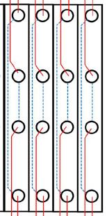
4.1.15. Enclosure Main - DIN Rail
House Trailer Either switch operate both rams Both rams operate at the same time Operating the switch ramps up the pump and gives a direction command to the valve


Pre-Alginment Checks Date: Time: Job#
Encoders Calibrated
Technician Name:
Encoder 1 Reading count:
Encoder 2 Reading count:


NOTE: Some trailers have switches for Left lower and Upper, and Right Lower and upper work lights on the 3-pin [house-lights] box on each side of the gooseneck
the suspension, clip-on rams and other auxiliary functions when specified
tail, Indicators, No.plate lights Feed to 3-pin plug enclosures for House lights (on Brown wire) Feed to beacon switch or socket (when specified)
Function and Notes
Trailer lights, Screen power and CAN,
Charge current from truck to trailer (option)
All gooseneck side lights terminate to BROWN Both Gooseneck 3-pin enclosures terminate to BROWN (option) May require (2mm)blue to main enclosure and (4mm)Blue back again for leg lights
left chassis rail under the powerpack
7-core cable to rear, exits box Powerpack On top of Gooseneck
Yanmar 4TNV 98 Revs set at 1800rpm and 2400 rpm. Rexroth 28cc pump with electronic load sense controller 12 volt start and charge Battery isolator on front of powerpack when specified
Battery pack for control system Right side of Gooseneck by main enclosure 2 x 12v AGM (Glass-pack) batteries
A 12-24volt charger uses the powerpack battery to charge the control batteries A re-settable circuit breaker controls the out current to the main enclosure 12v fuse for input 24v fuse for charge
Contains trailer ECU's and motor control (start, stop, Charge, revs etc relays)
Termination points for all major data and command supplies Has 12v, 24v and 5v supplies insideuse mustimeters for diagnostic procedures 24v Isolator on rear of box Ignition sw. on rear of box
Receives remote controller commands and send commands to trailer ECU's via the CAN system
Terminate inside main enclosure at lower work-lights switch
Main electrical enclosure Right side of Gooseneck
Remote Receiver Right side of Gooseneck on or in main enclosure
Lower Work lights Under short front deck


4.1.22. Charge
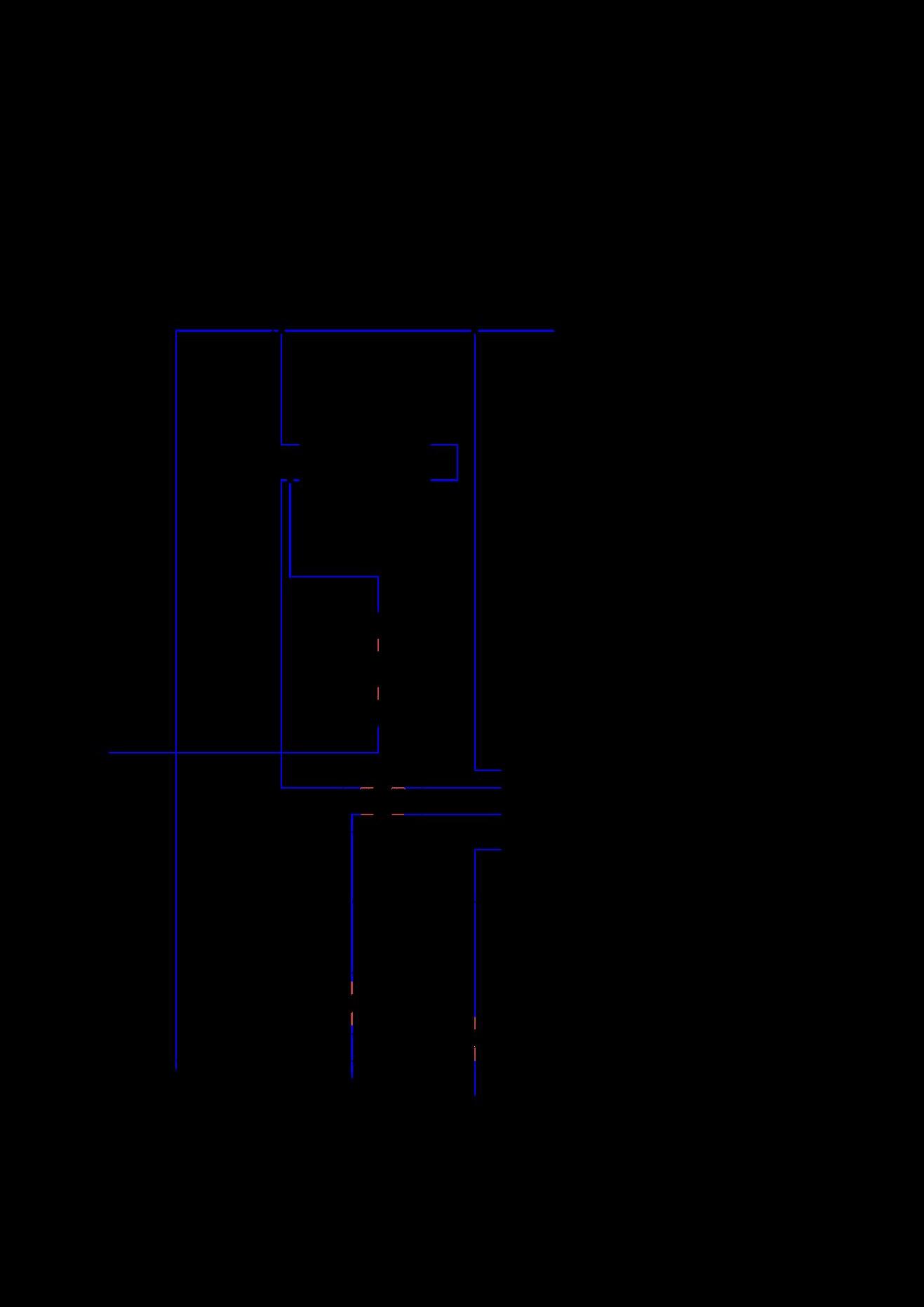


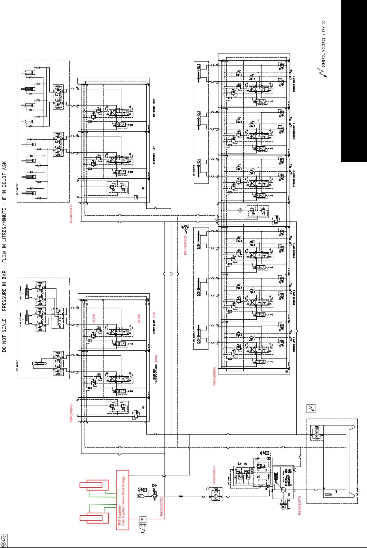
Hydraulic Schematic (Electronic Steering)


Battery (Starter Motor)
Battery (12V 36Ah AGM - Computer Control)
Battery Charger (24V DC 20A - Computer Control)
Coupling between Powerpack and Pump (Yanmar)
Engine (Yanmar)
Engine Mount (Matalastik)
Engine RPM Control Solenoid
Hydraulic Pump (Axial Piston, Variable Pressure)
Inline Filter Element (10Um)
Oil (Yanmar, 15/40W)
Return Filter Element
Rev-lifter Ram (16 Bore, 50mm Stroke)
Sight Glass (Level & Temperature)
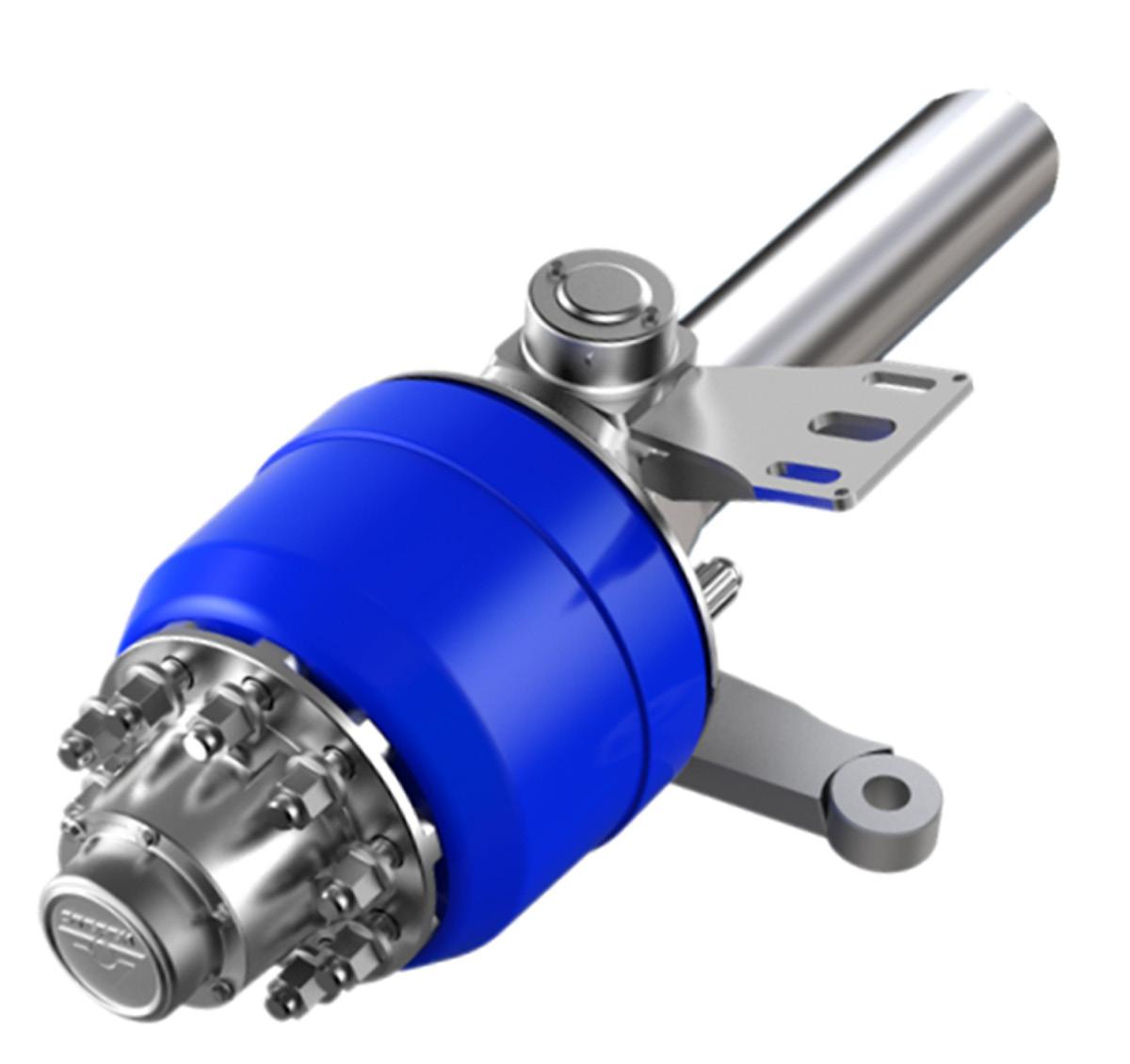
Axles (ROR Meritor - Steer L & R Set)
Bearing (BRG Spherical 50mm ID, Suspension Ram)
Bearing (BRG Spherical 70mm ID, Leg Pivot)
Bearing (Spherical 35mm ID, Steer Ram)
Bush (Command Steering, Axle Pivot - Oily)
Bush (Parallelogram Arm, 50.85mm x 40.4mm x 72mm)
Bush (D-Glide - Ram Eye)
Circlip (Leg Pivot)
Tyre 235 70 R17.5 XTE2
Wheels (17.5” x 6.75” 10 Stud Steel Rims)
CBNS70MF
AMREC36-12
ELBCDC2420
AM91/K0203M
AM4TNV98
AMAD6050223
SSA226-02
RXR940206717
RXR928006863
AMYM222240005
TDESS1810E
SMCD85N1650BXC6B
AMLG6-10T
ROCSK2
GE50DO2RS LS
GE70DO2RS LS
GE35DO2RS LS
TDCM013-A041-024
TDCM13-A10-P009
HTCOM-A1-P8
IKIC105
235R17.5
OGAGR365
M16 NYLOCK NUT
CM13-A10-P009
HTCOM-A1-P3
HTCOM-A1-P8 HYD51-001
BRG SPHERICAL GE70 DO
CIRCLIP INT 105mm
HTCOM-A5-P1
CM13-A10-P006
CM13-A10-P005
CIRCLIP INT 105mm
BRG SPHERICAL GE70 DO
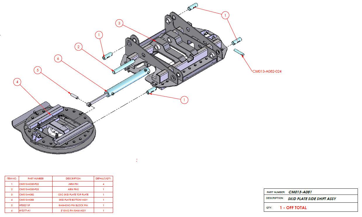
CM013-A041-024
CM13-A10-P009
CM087-007-004
CM087-007-005
22295_3.0x1.5x331
CM087-011-001
M24 NUT
CM013-A041-024
Accessory Valves (Rexroth, Gooseneck)
Accessory Valves (Rexroth, Rear of Main Chassis)
Accumulator (AES - 35L/260bar)
Cartridge Valve (Counter Balance)
Cartridge Valve (Counter Balance, Side Step)
Diverter Valve (Electric, 6 port, 3/8”, 24V, King & T Diverter)
Handle (Suspension Lock)
Pressure Sensor (0-280bar)
For repairs, quote serial number on valve as reference.
For repairs, quote serial number on valve as reference.
AM3426010628
HYCBPA-20M
HYCBPA-08
HY4003799
AMDCV40-H
RXR917A05562
Solenoid Valve (N/O, 1-Way Check, for AES System)
Steering Valves (Rexroth)
Suspension Isolation Valve Coupling (Biscuit)
RXR940205272
For repairs, quote serial number on valve as reference.
TDLVC-S753A
Valve Assembly (Suspension Locks with Handle) TDLVASS
Gooseneck Ram (2 Stage, 2300mm Stroke)
Landing Leg Ram
Steering Ram (Victor - 3.0” x 1.50”, 331mm
Stroke, including Transducer)
Steering Ram Transducer (331mm Stroke)
Suspension Ram (6”, 640mm Stroke)
King-pin Slider
Air Toggle Switch
TDHYD36-A1
HYD50-003
TD22295
TDLA4792
TDHYD51-001 REV B
HYD77-A1
SL216050
Brake Chamber AL24SD
Brake Chamber for Deck Locks (T30) AL30RS
Drain Valve (Pull) WH12104
Quick Release Valve (Wabco, 0psi crack) WA973/500/000/0
Spring Brake Chamber (24/30) AL2430SB
Yard Release Valve SL17600B
Cable (Devicenet, DataThick, Purple, PUR Sheath)
Cable (Devicenet, DataThin, Purple, PUR Sheath)
Cable (Olflex Truck Control Cable, 2x6, 3x1.5, 2x1.5)
Controller Plug (154 Pin)
Controller BODAS RC12-10/30
Controller BODAS RC28-14/30
Display Unit
Display Unit Mounts
Display Unit Plugs
Gooseneck Rotary Encoder
Remote Control (Transmitter/ReceiverCustom)
Elbow Connector (Encoder, 5 Pin)
5.5.1. Plugs & Sockets
15-Pin Socket (Round)
Anderson Plug Kit (2 Pole, 350A)
Housing Base Mount (for HD64 Connector)
EL2170344
EL2170345
EL7027093
RXR902603622
RXR917A08181
RXR917A07683
RXR917010009
RXR917010015
RXR917010017
ELRM9000
ELWACA057 (alternitive)
TDDYNAMIC
EL22260128
HA8JB007242-011
ELACX2764
EL79164400
Housing Top Entry (for HD64 Connector) EL19111900
Ignition Switch YANMAR
Insert Female (for HD64 Connector)
Insert Male (for HD64 Connector)
Pin Female (for HD64 Connector)
Pin Male (for HD64 Connector)
Socket (2 Pole, Marine)
Suzi Cable (Spiral, 15 Core, 4m)
15-Pin Plug (Round)
8-Pin HD30 Circular Connector (Motor Plug)
Inclinometer
EL11273000
EL11272000
EL13163300
EL13162300
HA2741
HA8KA007648041
HA8JA007241-021
ELACX2921
ELJD2110
Combination Light (LED Indicator/Stop/Tail, UV resistant) HA2331
Marker Light (Green)
HA95963055
Licence Light (LED) HA2559
Marker Light (Red/Amber) HA2053
Marker Light (White) HA2054
Indicator Light (Amber, Side) HA2031
Indicator Light (Amber, LED, Rear) HA2151
Reflector Circle (60mm, Amber) HA2916
Reflector Circle (60mm, Clear) HA2917
Reflector Rectangle (105mm x 55mm, Red) HA2926
Work Lamp (LED) HA1539
Strobe Beacon 85213A
5.7.
DO NOT OVERTAKE Sign (NZ)
Trailer Decals
TRT Name Plate (AU, Alloy)
5.8.
Kingpin - 2.0" Bolt up
CIXT037/A
TRT Custom
TDTRTPNZ
JTKZ151601 2”
Slew Ring for House Trailer L:VI085A28
TRT can provide a power pack service kit, or any individual components from the kit. The kit includes:
Fuel filter
Oil filter
Air filter (inner element)
Air filter (outer element)
Vee Belt
Yanmar Oil 15/40W - 5 litres
Yanmar Coolant - 5 litres
Pressure filter element, and
Return filter element.
Source: www.assalistefen.com/it/assali
(*) installation length is the distance between the actuator support and the center of the hole on the slack adjuster with the brake at rest. It is good practice, even though not strictly necessary, to install a return spring on the slack adjuster.
3.1 - TM SERIES AXLES
Procedures
Frequency
Specific service and maintenance intervals must be set by the person in charge of the vehicle or vehicle fleet depending on the operating conditions in which these vehicles work. Here, at any rate, are the following minimum conditions which must be complied with.
TM - Disc & Drum BRAKE AND WHEEL TIGHTENING CHECK
TM - Drum
• CAMSHAFT BUSHING AND SLACK ADJUSTER LUBRICATION
• OIL LEVEL CHECK (for oil-lubricated hubs)
TM - Drum COMPLETE BRAKE MAINTENANCE
TM - Disc BRAKE INSPECTION AND MAINTENANCE
TM - Disc & Drum HUB AND BEARING INSPECTION WITH OIL RETAINER REPLACEMENT
TM - Disc & Drum COMPLETE OVERHAUL OF THE HUB
• Before starting to work
• After 150 km
• After 1,500 km
• Every three months
• Every time the wheels are removed
• Every time the brakes are overhauled
• Every three months
NOTE: shorten the interval to six weeks when using brake lubricant other than the recommended lubricant or when the vehicle works in environments with a strong presence of abrasives
• Prior to the second yearly trailer overhaul
• Subsequently every year
• Inspect pads, caliper and disc every 50,000 km or three months
• Carefully clean caliper and rotor every 100,000 km or six months and every time the pads are replaced
• Every time the hub is removed
• Every year after the first complete overhaul
• If faults are found during inspection
• Before the second yearly overhaul or every 200,000 km, whichever comes first
• Subsequently every year or 100,000 km, whichever comes first
Recommended tightening torques in Nm (10 Nm ~ 1 kgm):
4.1 - DISC & DRUM BRAKES Description
Hub cap screws (grease lubrication) 16-30 11-15 11-15
Hub cap screws (oil lubrication) 25-30
Axle end lock nut 350-375
M22x1.5 nut (for steel and alloy wheels)
4.2 - ELSA 195 DISC BRAKES – TM and LM SERIES AXLES
Description
Rotor -
screws
4.3 - ELSA 2 or ELSA 225 L DISC BRAKES –TA and LM SERIES AXLES
Description Torque value
Rotor - hub fastening screws 230-270
Caliper fastening M18 screws 380-420
ABS sensor support screws 20-25
Brake actuator nuts 180-210
The above-mentioned torque values are for dry tightening (with high friction)
5.1 - RECOMMENDED LUBRICANTS FOR HUB BEARINGS
BRAND
GREASE Type
MERITOR Hub Grease Blue lithium EP2
SHELL
Calithia EP2T
Alvania EP (LF) 2
MOBIL Mobilux EP2
CASTROL
TEXACO
Spheerol EPL2
Multifak EP2
TOTAL Multis EP2
B P LS EP2
ESSO Beacon EP2
SILKOLENE G62
EUROL
Universalfett EP2
ELF Lithium EP2
AXLE CHRISTIERNSSON Lithac 162 EP
FINA Marson EPL2
SKF LGEP2
G B
OIL Type
Spirax EP90
Mobilube GX 90
Hypoy EP90
Multigear EP85W/90
Total EP90
Gear Oil 90 EP
GX 85/90
Lithium EP2 ---
5.2 - LUBRICANTS FOR CAMSHAFT BUSHINGS AND BRAKE COMPONENTS
TotalFina CERAN WRC2
5.3 - SPINDLE LUBRICANTS
Optimol Optimoly White Paste T, recommended for application on bearing housings to prevent rust formation and facilitate subsequent hub removals
5.4 - QUANTITY OF LUBRICANT
5.4.1 - Axles with oil lubrication: Fill the hub up to the level marked on the hub cap (about 380 ml ).
5.4.2 - Axles with grease lubrication (quantities in grams )
5.4.1 - Axles with oil lubrication:
Fill the hub up to the level marked on the hub cap (about 380 ml ).
5.4.2 - Axles with grease lubrication (quantities in grams )
BEFORE STARTING TO WORK
- Check the brake system an d suspensions (hoses, fittings, equipment, …)
- Check that brakes and suspensions work properly
- Check the working height of the suspension
- Check any axle lift device and related system
AFTER 1,000 km
- Check the tightening torques of the components of the suspension
- Check air system hoses and equipment
- Check the working height of the suspension
- Check for oil leaks in shock absorbers
- Check that optional equipment works properly (lift unit, lift- lower valves …)
AFTER 10,000 km AND SUBSEQUENTLY EVERY 10,000 km
In addition to the 1,000 km checks:
- Check the shock absorber bushings
- Check tire wear (if tire wear is uneven check the trailing arms elastic bushings for damage and check axle alignment as described in chapter 9)
- Visually check the air springs
EVERY 100,000 km
In addition to the 10,000 km checks:
- Check proper operation of every single component in the air system
- Check the front suspension supports, their inner part and the wear plate near the trailing arm
We particularly recommend checking the tightening torques of suspension components at the first 1,000 and 10,000 km .
6.2. Axle Parts List
Source: www.assalistefen.com/it/assali
Complete Assembly Axle S121930A001A
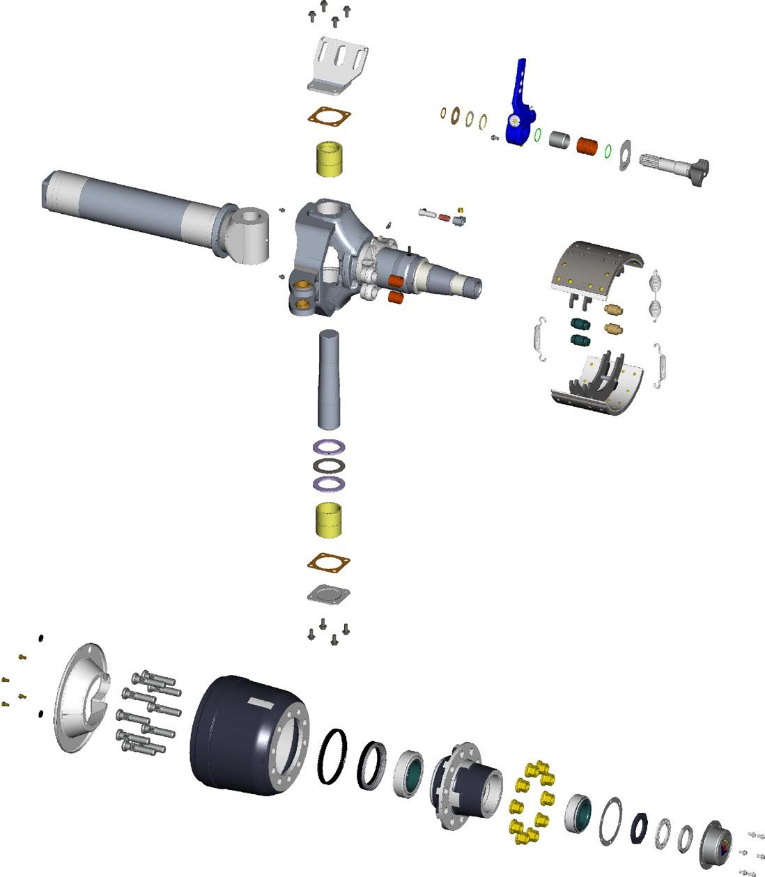
& S121930A051A - Rev.0
2

assembly (*)
Brake assembly (***)
S121930A001A & S121930A051A - Rev.0
1 Brake shoe lined assembly M04004A 2 Brake lining, anchor end C09011A
Brake lining, cam end C09012A
Brake shoe C07006A 5 Roll pin C99007A
6 Return spring C05001A 7 Retaining spring C05006A 8 Cam roller C06001A 9 Roller retainer clip C07007A 10 Anchor pin M05001A Rivet (brake shoe) C99001A Brake linings kit K02003A
Descriptions and specifications were in effect at the time of this publication and are subject to change without notice or liability Assali Stefen reserve the right to make design improvements, change or discontinue parts at any time
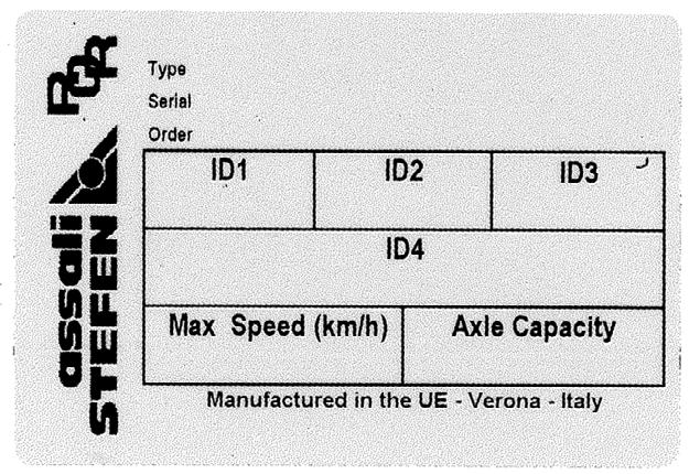
* IMPORTANT: The serial number engraved on the name-plate is input into the manufacturer’s electronic archives. By referring to this number you can, at any time, have information or genuine spare parts.
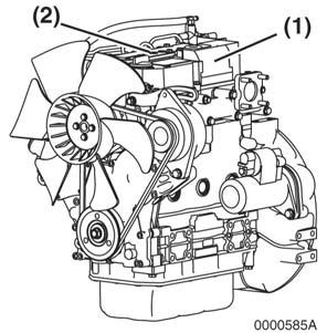
Component Identification
Figure 4-1a, Figure 4-1b shows where the major engine components are located.
4TNV98 ENGINE
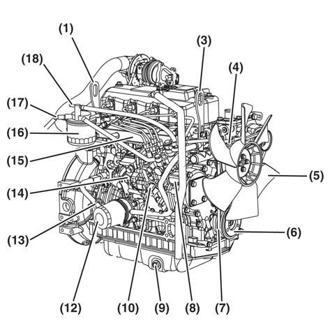
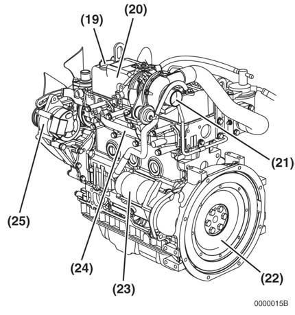
Figure 4-1a
4TNV98 & 4TNE98 Diesel Engine
(1) Lifting Eye (Flywheel End).
(3) Lifting Eye (Engine Cooling Fan End).
(4) Engine Coolant Pump. (5) Engine Cooling Fan.
(6) Crankshaft V-Pulley. (7) V-Belt.
(8) Side Filler Port (Engine Oil). (9) Drain Plug (Engine Oil).
(10) Fuel Injection Pump. (12) Engine Oil Filter.
(13) Dipstick (Engine Oil) (14) Governor Lever. (15) Intake Manifold. (16) Fuel Filter.
(17) Fuel Inlet. (18) Fuel Return to Fuel Tank.
(19) Top Filler Port (Engine Oil). (20) Rocker Arm Cover.
(21) Air Intake Port (From Air Cleaner).
(22) Flywheel. (23)Starter Motor.
(24) Exhaust Manifold. (25) Alternator.
4TNE98 ENGINE
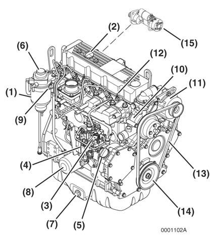
Figure 4-1b
(1) Fuel Filter / Water Separator
(2)Top Filler Port (Engine Oil)
(3) Governor Lever
(4) Fuel Injection Pump
(5) Side Filler Port (Engine Oil)
(6) Fuel Priming Pump
(7) Drain Plug (Engine Oil)
(8) Engine Oil Filter
(9) Dipstick (EngineOil)
(10) Engine Coolant Pump
(11) Alternator
(12) Glow Plug
(13) V-Belt
(14) Crankshaft V-Pulley
(15) Starter Motor
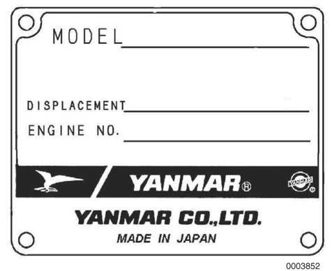
Figure 4-2 shows the location of regulatory and safety labels on Yanmar TNV & TNE series engines.
4TNE98 ENGINE
4TNV98 ENGINE
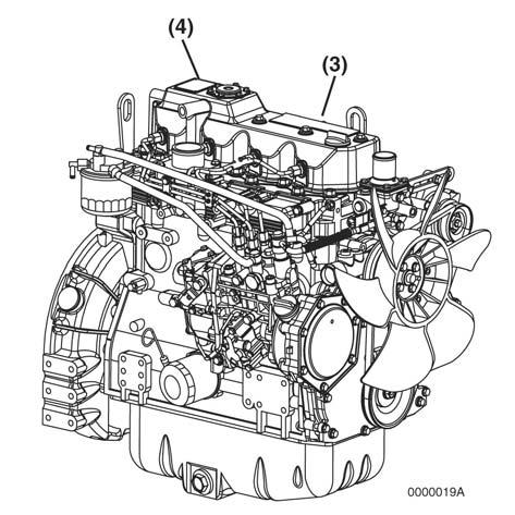
Figure 4-2
The typical location of the emission control information label shown (Figure 4-2 (2), (3)).
The typical location of the engine nameplate is shown (Figure 4-2 (1), (4)).
EPA / ARB Regulations - USA Only
Yanmar engines meet Environmental Protection Agency (EPA) (U. S. Federal) emission control standards as well as the California Air Resources Board (ARB, California) regulations. Only engines that conform to ARB regulations can be sold in the State of California.
Refer to the specific EPA / ARB installation (page 40) and maintenance (page 40) in the Periodic Maintenance Schedule section of this manual.
4TNV98 & 4TNE98 Diesel Engine
4TNV98 EPA Tier 2
Engine Model
4TNV98
Version VM (SDF)
Type Vertical In-line Diesel Engine
Combustion System Direct Injection
Aspiration Natural
No. of Cylinders 4
Bore × Stroke
Displacement
Idling
Engine Weight (Dry) with Flywheel Housing
3.858 x 4.331 in. (98 x 110 mm)
cu in. (3.319 L)
518.2 lb (235 kg)
PTO Position Flywheel End (Option)
Direction of Rotation
Cooling System
Lubricating System
Counterclockwise Viewed from Flywheel End
Liquid-Cooled with Radiator
Forced Lubrication with Trochoid Pump
Normal Oil Pressure at Rated Engine Speed 42 - 57 psi (0.29 - 0.39 MPa, 2.96 - 3.98 kgf/cm²)
Normal Oil Pressure at Low Idle Speed 8.5 psi (0.06 MPa, 0.6 kgf/cm²)or greater
Electric Starting - Starter Motor: DC12V, 3.1 hp (2.3 kW)**
Alternator: DC12V, 40A** Starting System
Recommended Battery Capacity: 12V, 64 Amp-Hour (5h rating)**
Dimensions (L × W × H)* 28.31 x 19.61 x 29.21 in. (719 x 498 x 742 mm)
Engine Oil Pan 11.1 / 6.3 qt (10.5 / 6.0 L) (Dipstick Upper Limit / Lower Limit)
Engine Coolant Capacity 1.1 gal (4.2 L) Engine Only
Standard Cooling Fan 16.14 in. (410 mm) O.D., 6 Blade Pusher-Type**
* Engine specifications without radiator
** May vary depending on application.
*** Engine oil capacity for a “Deep Standard” oil pan. Refer to the operation manual provided by the driven machine manufacturer for the actual engine oil capacity of your machine.
&
Cooling System
Check and Refill Engine Cool
Check and Clean Radiator Fins
Check Engine Coolant Temp. Indicator
Check and Adjust Cooling Fan V-Belt
Drain, Flush and Refill Cooling System with New Coolant
Adjust Intake / Exhaust Valve Clearance
Cylinder Head Lap Intake / Exhaust Valve Seats
Indicators
Battery
Engine Oil Level
Check Engine Oil Pressure Indicator
Drain and Fill Engine Oil Engine Oil
Replace Engine Oil Filter
and after Engine Speed Control Check and Adjust Governor Lever and Engine Speed Control
Emission Control Warranty Inspect Crankcase Breather System
Inspect, Clean and Test Fuel Injectors
Check and Refill Fuel Tank Level
Check Fuel Filter Indicator
Fuel Tank
Drain Fuel Filter / Water Separator
Check Fuel Filter / Water Separator
Clean Fuel Filter / Water Separator
Replace Fuel Filter
Hoses Replace Fuel System and Cooling System Hoses
Intake and Exhaust
or Replace Air Cleaner Element
or every year whichever comes first
or every 2 years
NOTE: These procedures are considered normal maintenance and are performed at the owner’s expense.
TRANSMITTER
RED LED
Is OFF
Transmitter is working correctly
Blinks The battery is nearly flat
Is ON for 2 seconds
Transmitter not working correctly
Blinks once At power ON – the transmitter has detected that the E-stop is pressed or damaged
Blinks Twice At power ON – the transmitter has tried to start with a safety switch in the ON position
Blinks 3 times When turned on = Battery is flat
Blinks 3 times At power ON – the transmitter has tried to start with a Paddle out of centre or damaged
BEEPS A BEEP will accompany the LED flash pattern
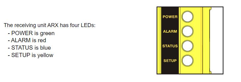
ALARM LED
Is OFF Receiver is working correctly
Blinks once Error on the STOP outputs
Blinks Twice Error on the Safety Outputs
Blinks 3 times Error on commands corresponding to direction
Is ON Configuration fault
SET-UP LED
Is OFF Receiver working correctly
Blinks once Error in Address key
Blinks Twice Error in Memory Board
LastUpdated 01/12/2023
STATUS LED
Is OFF No radio link
Blinks Slow Over voltage at power supply
Blinks Fast Data received from transmitter
Is ON
Over-current at PWM analogue output
P/Design/01 ESS trailers/001 Electrical
Remote Blink and Beep codes Garth Uren


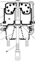
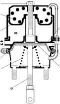
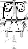
Ram Head-nut

Transducer

Plug and
Spear and Piston

Transducer
Magnet
Transducer
Rod
Transducer O-ring and Locating ring (Grub-screw slot)

1. Remove the ram from the trailer, Clean it and mount it in a vice, or similar, for dismantling
2. Unwind the head-nut and carefully remove the ram spear and piston from the ram Barrel. Take care to keep the Spear etc in line with the barrel as it is being removed as the transducer slides inside the ram spear.
3. Remove the 2 screws that retain the Plug to the barrel
4. Locate and remove the small grub screw that retains the Transducer in the ram
5. Pull the transducer out of the end of the barrel. Take care to thread the wires and plug through the cavity as the transducer is withdrawn from the ram
1. Inspect the ram barrel and spear to ensure it is ok to be re-used
2. Unsure the O-ring on the replacement transducer is lubricated
3. Run a draw-string through the cavity and tie it lightly to the plug.
4. As the transducer is slid into the barrel, draw the plug and wiring through the cavity (Do NOT damage the plug or wires during this process)
5. Push the transducer ‘home’ onto the seal cavity, and refit the grub-screw to hold it in place. Check the transducer is located properly and held in place
6. When the plug is all the way through the cavity, and in the correct position, secure it with its mount plate and screws.
7. Reassemble the ram by carefully sliding the piston and spear over the Transducer as it is inserted into the barrel. Tighten the Head nut
8. Test the ram for function and seal leaks before refitting
9. Test the transducer output is correct and stable as the ram is being tested.
Customer:
Lead Trailer - Module number
Date:
HPU Upper setting
#1 B-Module number 1a Clip-on HPU Stand-by
#2 B-Module number 2a Clip-on
SPEED-THRESHOLD SETTINGS (Shows ring around function as it becomes isolated)
Joystick Override Rear axle straight Crab Auto
Controller Master Switch 24V
Batteries
Switch Isolates all 24V supply
Ignition Switch Key Starts and Stops Motor
E-stop at Main Enclosure
Gooseneck - UP / DOWN
Suspension Left - UP / DOWN
E-stop Button Stops Motor and controllers
Suspension Right - UP / DOWN MANUAL REMOTE (Tethered)
Revs REMOTE / OFF / HIGH
/ Off
Widening Controls Where it plugs in Ramps
Ramp Float
Clip-on ram controls Individual Switches Both sides
Clip-on isolation
Engine start / Stop
Gooseneck UP / DOWN
Suspension Left - UP / DOWN Paddle
Suspension Right - UP / DOWN Paddle
Ramps Switch
Ramp Float Switch
Steer Manual Auto
Steer Direction Paddle
Horn Button
Screen inputs
Diagnostics
Auto steer
Crab Auto
Manual steer
Steer pivot point
Speed cut-out for steer functions
Adjustable using Bodas if customer requires a change
Options go grey and cant be selected
Valves accessible on wheels
Decals Correct
OVERSIZE sign
Steer Alignment
TRAILER CONFIGURATIONS TYPE
Splitting and joining the trailer
Light bars
Push bar
Dolly hook-up and hydraulic supply
Importance of clean couplers
Importance of clean couplers electrical Plugs
DO NOT HOT PLUG!
Screen set-up
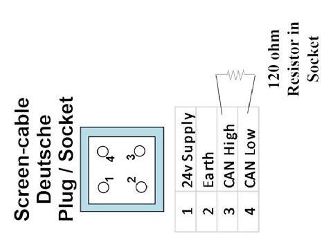
120ohm resistors
TRAINER (Name and Signature)
Acknowledging I/we have run the trainee through the function checks stated above.
Care in moving screen between trucks
Fitted in CAN looms be careful if servicing electrical plugs
TRAINEE (Name and Signature)
Acknowledging I/we have been run through the function checks stated above.
DATE