PRODUCT CATALOGUE


BRACKETS & CLAMPS
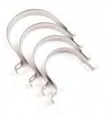
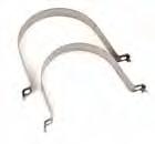
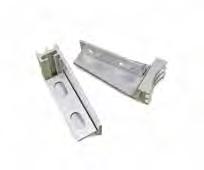
Structural aluminium alloy brackets that offer a robust fitting for small flat signs on 50mm NB and 65mm NB poles. Highly resistant to corrosion and impacts.
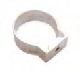
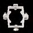
SINGLE AND DOUBLE SIDED BRACKETS
BOLTS & WASHERS NOT INCLUDED
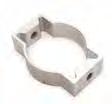
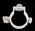
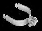
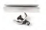
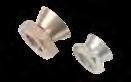
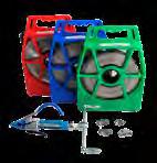
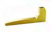
FRISBEE BRACKET
& WASHERS NOT INCLUDED
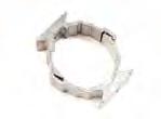
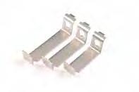
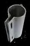
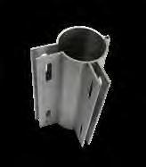
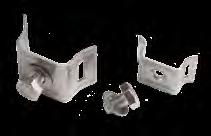
SINGLE SIDED HEAVY DUTY DOUBLE BOLT UNI-CLAMP
BOLTS, WASHERS AND NUTS INCLUDED
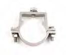
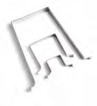
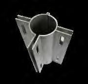
DOUBLE SIDED HEAVY DUTY DOUBLE BOLT UNI-CLAMP
BOLTS, WASHERS AND NUTS INCLUDED
BOLTS & WASHERS INCLUDED
Signfix clamps, brackets and clips secure signs to posts of every shape and size. Signs installed using Signfix products offer greater on-site flexibility and can be offset with ease.
The stainless steel product range is manufactured using AISI 304 alloy, a highly durable material particularly beneficial when impact resistance and anti-corrosion is important.
The stainless steel fittings have been subjected to ASTM B117 salt-spray testing for 500 hours with no significant corrosion. They are highly suitable in coastal regions.
With a market presence of over 20 years, the Signfix range of superior quality products have proven longevity.
&
BOLTS & NUTS NOT
BOLT & NUT INCLUDED

*LIGHT RECTANGULAR HOLLOW SECTION POSTS **HEAVY RECTANGULAR HOLLOW SECTION POSTS BOLT & NUT NOT INCLUDED
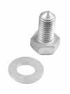
FIXINGS FOR STAINLESS STEEL CHANNEL CLAMPS & BRACKETS
The aluminium alloy M10 channel provides a robust structure for Signfix clamps, brackets and fixings.
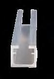
M10 CHANNEL
CODE DESCRIPTION
M10-CHANNEL/6 M10 CHANNEL 6M LENGTH MILL PER LENGTH
High performance M10 trilobular fixings to prevent theft and vandalisation.
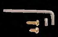
TRILOB SPANNER / TRILOB HEX BIT / TRILOB BOLT
TRILOBKEY SECURITY KEY FOR TRILOBULAR SCREW
M10-TRILOB20SS M10 X 20MM TRILOBULAR COUNTERSUNK SET SCREW ZY
M10-TRILOB21CP M10 X 21MM TRILOBULAR CONE POINT
M10-TRILOB25ZY M10 X
M10-TRILOB40 M10 X 40MM TRILOBULAR BOLT ZY
Street blade brackets are available for 50NB & 65NB poles.

CODE
SNB-150-50 50MM
SNB-200-50 50MM
SNB-150-65 65MM
SNB-200-65 65MM
BOLTS, WASHERS AND NUTS INCLUDED
SNB2-150-5050MM
SNB2-200-5050MM
BOLTS, WASHERS AND NUTS INCLUDED
CODE
SNB3-150-5050MM
SNB3-200-5050MM
BOLTS, WASHERS AND NUTS INCLUDED
CODE DESCRIPTION
OSBMSNP-01 MINI OFFSET BRACKET C/W TWO M10 SLOTTED HOLE ANGLE EACH
BOLTS, WASHERS AND NUTS NOT INCLUDED
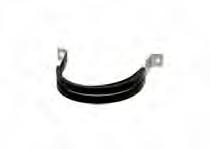
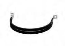
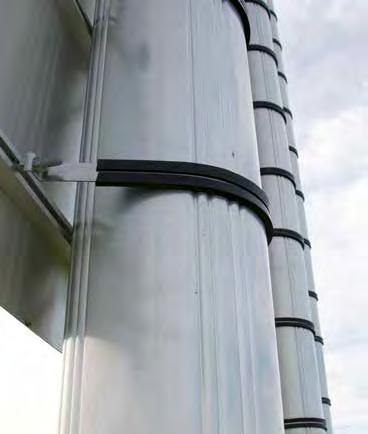
Signfix offers the sign industry the versatility of stainless steel bands and fittings specially designed and packaged for sign makers and installers. The premium quality stainless steel is compatible with other Signfix materials, suiting small to large diameter poles.
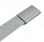
STR13, STR16, STR19 – to calculate the approximate amount of banding required, multiply the pole diameter by 3.14 or pi (π), then add on an extra 120mm for fixing with the Band-It Tool, e.g. 114mm OD pole x 3.14 = 358mm + 120mm = 478mm.
Also available: 316 grade s/steel for coastal regions.


BRACKETS & CLAMPS
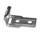
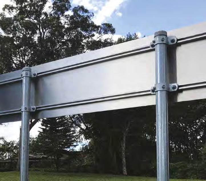
Available from Signfix, Hazard Board Heavy Duty Brackets are designed to mitigate road signs spearing vehicle windscreens. TMR Queensland has developed and tested a new design and issued Standard Drawing 1452. By strengthening the post connections with heavy duty clamps, the risk of sight board signs spearing is reduced as the sign is pulled down with the post on impact, rather than sliding off the post.
CODE DESCRIPTION
HAZ-BRACKETKIT HAZARD BOARD HEAVY DUTY BRACKET KIT QLD TMR SPECIFICATION
DRAWING SD1452
This project was awarded the 2018 Innovation Award at the Department of Transport and Main Roads Engineering Technology Forum
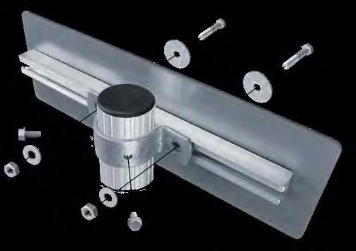
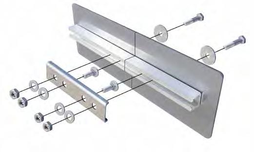
ITEMDESCRIPTION
1* M10 X 55 HEX BOLD. GRADE 4.6 GALVANISED
2 FLAT WASHER 40 OD X 11 ID X 2MM THICK GALVANISED
3*** ALUMINIUM SIGN FACE
4*** TYPE 1 ALUMINIUM STIFFENER RAIL
5 M10 X 30 COACH BOLT. GRADE 4.6 GALVANISED
6 SPLICE PLATE ALUMINIUM
7 M10 FLAT WASHER GALVANISED
8 M10 HEX NUT. GRADE 4.6 GALVANISED
9 HEAVY DUTY POST CLAMP GALVANISED
10** M8 X 20 TAPITE HEX SELF-TAPPING SCREW
11 SIGN POST 60 OD
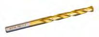
12 7.3MM DRILL BIT
Notes:
* Drill 10mm dia. holes through stiffener rail and sign face to fit M10 bolts.
** Drill 7.3 dia. holes in post to accept Taptite screws
*** NI = Not Included
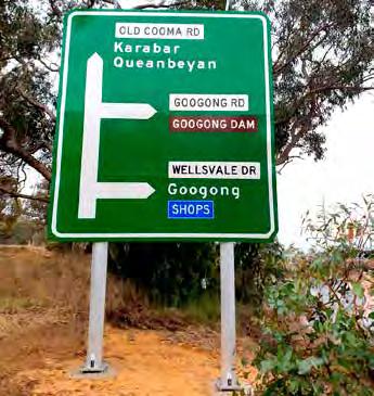
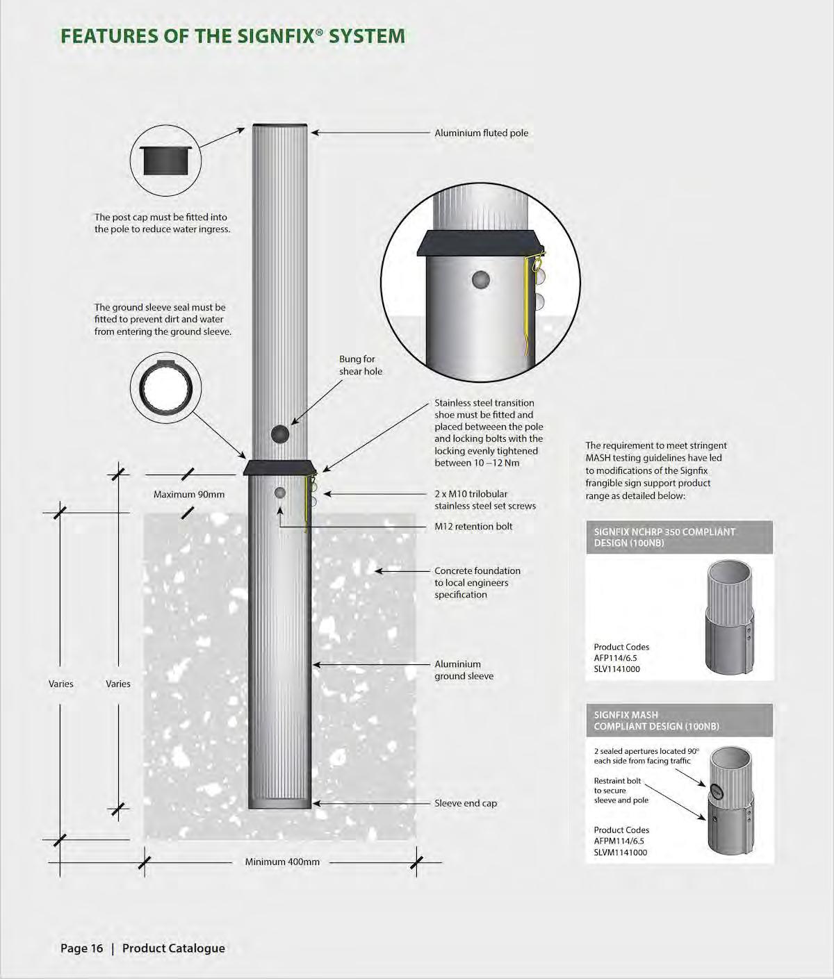
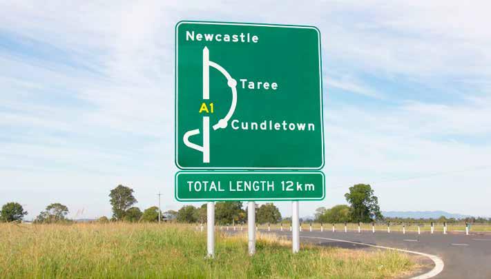
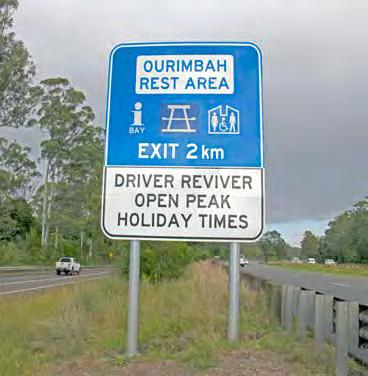
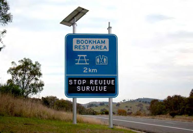
Signfix™ is Australia’s leading frangible aluminium signpost range and used extensively by state and territory road authorities. In addition to its compliant passive safety features, Signfix is popular with construction contractors due to its lightweight design and ease of installation.
The Signfix range can be installed as a single sign support or a multi leg assembly. The system allows up to 16m2 single sign dimensions in the major Australia wind zone regions.
Signfix frangible poles range 60-114mm in outer diameter and hold up to 16m2 road signs in Australian wind regions.
> Signfix fluted poles come in 3.2m-6.5m lengths, depending on the pole diameter.
> Pole sizes: Ø60mm, Ø76mm, Ø89mm, Ø102mm, Ø114mm.
> Poles inserted into corresponding sized aluminium ground sleeve sockets, set in concrete foundations.
> Ground sleeves vary 300-1000mm in length
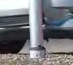
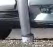
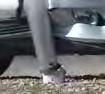
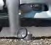
> Upon vehicle impact, the sleeve acts as a shear point, safely breaking away the pole at the socket top.
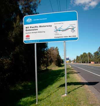
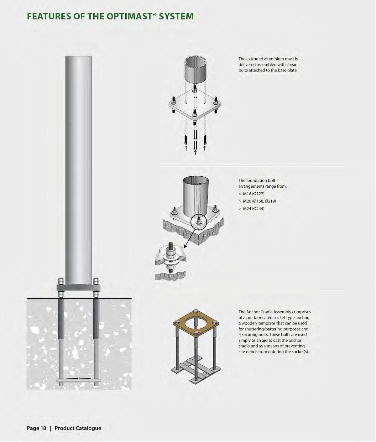
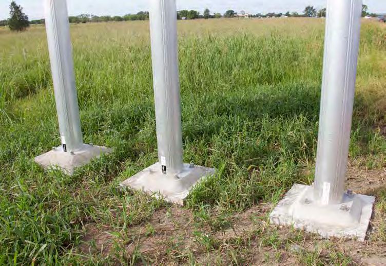
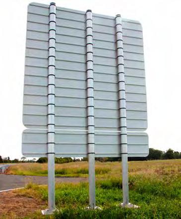
We are pleased to introduce Optimast® into the market, a complimentary frangible signpost range for larger sign dimensions of up to 40m2 across the major Australia wind regions. The increased signage area enables road designers and engineers to specify passive sign structures for large scale traffic messaging such as highway directional signage.
Both the Signfix and Optimast ranges are convenient out of the box products, thus requiring very little intervention from sign installation crews or civil engineers.
Optimast range 127-244mm in diameter and hold up to 40m2 road signs in Australian wind regions
> Optimast poles come in 5.0m-8.0m lengths, depending on the pole diameter
> Pole sizes: Ø127mm, Ø168mm, Ø219mm, Ø244mm.
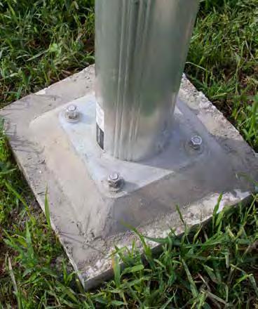
> Poles are affixed to base plates with shear bolts.
> The base plates are attached to anchor cradles set in concrete with foundation bolts.
> Upon vehicle impact, shear bolts safely breakaway the pole from the base plate.
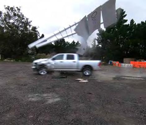
Austroads, the peak body of Australasian road transport and traffic agencies, require new and existing road safety products to comply to the updated testing guidelines of AS/NZS3845.1 (2015) and AS/NZS3845.2 (2017). Road safety products must now be tested to the American Association of State Highway and Transport Officials (AASTO) 2009 Manual for Assessing Safety Hardware (MASH) guidelines. MASH testing supersedes NCHRP 350 testing for Australia and New Zealand road barrier products. After extensive vehicle impact tests were undertaken on the Signfix and Optimast product ranges by a leading FHWA testing facility, the Signfix and Optimast product ranges are MASH compliant and approved by Austroads Safety Barrier Assessment Panel (ASBAP) for use on Australia and New Zealand road networks.
Signfix and Optimast product ranges are MASH compliant and approved by Austroads Safety Barrier Assessment Panel (ASBAP) for use on Australia and New Zealand road networks.


> Longstanding performance in Australia conditions.
> The patented Signfix fluted pole and socket system meets or exceeds the MASH testing thresholds for frangible structures.
> Successfully under taken rigorous impact testing with 1100kg and 2270kg vehicles at speeds of 30km/h and 100km/h by a leading FHWA accredited testing agency.
> Occupant Impact Velocity below the preferred 3.0m/s thresholds (4.9m/s maximum).
> Occupant Ride-down Deceleration well below the preferred 15.0g threshold.
> Deformations of vehicle occupant department and post impact vehicle trajectory within acceptable limitations.
> The lightweight extruded aluminium components are easy to handle and convenient to transport.
> Simple to install with no specialist equipment required – props are not required for installing ground sleeves and larger poles during the foundation hardening process.
> Damaged poles are easily removed, and replacement poles re-installed into existing sleeve foundations.
> Wind chart system allows installers to easily determine optimal pole configuration (number of poles and size).
> Clear instruction manuals provided.
> Structurally designed to support a sign area of up to 16m2
> The fluted pole diameter sizes fit all standard bracket types.
> Lightweight Signfix aluminium frangible poles are similar in strength to steel equivalents.
> Patented stainless-steel transition shoe is supplied to prevent wear and eliminate any electrolysis action between the locking bolts and pole.
> Revised MASH design range comes with polymer seals, plugs and caps to prevent water ingress.
> Corrosion resistance from high quality marine grade aluminium alloy.
> Proven performance in the UK, Germany and France, Optimast complies to BS EN 12767 and has achieved the highest safety accreditation, 100 NE3.
> The Optimast system meets or exceeds the MASH testing thresholds for frangible structures.
> Successfully under taken rigorous impact testing by a leading FHWA accredited testing agency.
> Occupant Impact Velocity below the preferred 3.0m/s thresholds (4.9m/s maximum).
> Occupant Ride-down Deceleration below the preferred 15.0g threshold.
> Deformations of vehicle occupant department and post impact vehicle trajectory within acceptable limitations.
> The extruded aluminium mast (5-8m lengths), shear bolts and base plate are delivered fully assembled.
> Simple to install base plate with foundation bolts onto an anchor cradle socket set into a concrete foundation.
> Easy to replace damaged poles, which are easily removed and re-installed onto existing foundations.
> Wind chart system allows installers to easily determine optimal pole configuration (number of poles and size).
> Clear instruction manuals provided.
> Structurally designed to support large directional signs of up to 40m2
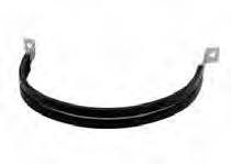
> Signfix provides specialised Optimast clamps with rubber lining to affix mast to sign channel.
> Strong extruded aluminium cylindrical design has similar strength to steel equivalents.
> Corrosion resistant high-quality marine grade aluminium alloy.
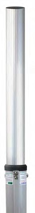
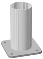
FLUTED ALUMINIUM POLES
The high-strength marine grade alloy used in 50NB and 65NB Signfix fluted aluminium poles is light weight and has excellent corrosion resistance.
Standard pole lengths:
50NB (60OD) > 3.2m, 4.0m
65NB (76OD) > 4.5m
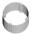
ACCESSORIES AND COMPONENTS
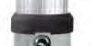
SLEEVE WEDGE
Standard zinc plated wedge. 60OD and 76OD sleeves are designed to be fitted with a standard wedge, allowing sleeves to be installed flush at ground level.
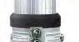
POLY POST CAP & POLY SLEEVE SEAL
To reduce water ingress the poly cap and poly seal tightly form firm fits at the top of the post and sleeve.
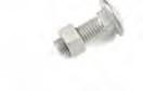
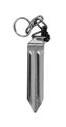
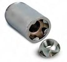
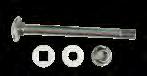
RESTRAINT BOLT
Securing the pole in the sleeve retained with a kinmar security nut and SS bolt.
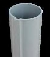
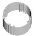
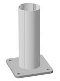
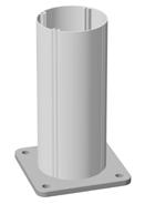
POWDER COATED ALUMINIUM GROUND SLEEVES
Designed to suit both 50NB and 60NB aluminium fluted and galvanised steel poles, Signfix ground sleeves are made from high strength marine grade alloy. The alloy has excellent corrosion resistance and over the years has proven performance with aluminium frangible poles.
GROUND SLEEVE LENGTHS
50NB (60OD) > 300mm, 400mm, 450mm & 600mm
65NB (76OD) > 600mm
Features include:
> The external shape ensures sleeves will not rotate when set in concrete.
> Internal dimensions of all sleeves are designed to be a snug fit with the pole.
> Sleeves are fitted with PVC end caps to prevent concrete entering the sleeve during installation.
Sleeves can be supplied with an M10 tapped hole located 15mm below the sleeve top, to fit either an M10 hex bolt or a trilobular security set screw. This option is ideal for securing PVC poles and in this instance, it is recommended that the sleeves are placed 30mm above ground level.

50NB
CODE DESCRIPTION
AFP060/3.2 50MM NB X 3.2M ALUM FLUTED POLE MILL FINISH
AFP060/4 50MM NB X 4.0M ALUM FLUTED POLE MILL FINISH
SLV060300 50MM NB X 300MM ALUM GROUND SLEEVE FOR 50MM NB POLE
SLV060300-DT 50MM NB X 300MM ALUM GROUND SLEEVE FOR 50MM NB POLE DRILLED & TAPPED W TRILOB
SLV060400 50MM NB X 400MM ALUM GROUND SLEEVE FOR 50MM NB POLE
SLV060400-DT 50MM NB X 400MM ALUM GROUND SLEEVE FOR 50MM NB POLE DRILLED & TAPPED W TRILOB
SLV060450 50MM NB X 450MM ALUM GROUND SLEEVE FOR 50MM NB POLE
SLV060450-DT 50MM NB X 450MM ALUM GROUND SLEEVE FOR 50MM NB POLE DRILLED & TAPPED W TRILOB
SLV060600 50MM NB X 600MM ALUM GROUND SLEEVE FOR 50MM NB POLE
SLV060600-DT 50MM NB X 600MM ALUM GROUND SLEEVE FOR 50MM NB POLE DRILLED & TAPPED W TRILOB
SLVWEDGE060 GROUND SLEEVE WEDGE
POLYCAP060 50MM NB POLY POST CAP
POLYSEAL060 50MM NB POLY SLEEVE SEAL
AFPMRST060 RESTRAINT DEVICE TO SUIT 50MM NB POLE
CODE DESCRIPTION
AFP076/4.5M 65MM NB X 4.5M ALUM FLUTED POLE MILL FINISH
SLV076600M 65MM NB X 600MM ALUM GROUND SLEEVE FOR 65MM NB POLE
POLEKIT076M 65NB KIT SET C/W POLYCAP076, POLYSEAL076, POLYPLUG076 X 2, M12 X 104MM RESTRAINT BOLT, KINMAR NUT, NYLON WASHER X 2
POLYCAP076 65MM NB POLY POST CAP
POLYSEAL076 65MM NB POLY SLEEVE SEAL
AFPRST076 RESTRAINT DEVICE TO SUIT 65MM NB POLE
KINMARSOCKETMKINMAR DRIVE SOCKET - M12
M – Denotes MASH range
FLUTED ALUMINIUM POLES
The high-strength marine grade alloy used in 80NB, 90NB and 100NB Signfix fluted aluminium poles is light weight and has excellent corrosion resistance.
Standard pole lengths:
80NB (89OD) > 5.5m lengths
90NB (102OD) > 6.0m lengths
100NB (114OD) > 6.5m lengths
ACCESSORIES AND COMPONENTS
TRANSITION WEAR SHOE
80NB, 90NB and 100NB sleeves are designed to be fit with a transition shoe & two trilobular fasteners.
The patented stainless steel transition shoe fits between the aluminium pole wall and M10 trilobular locking bolts, to prevent fracture points and eliminate any electrolysis action. The innovative stainless steel transition shoe MUST be placed between the pole and locking bolts and tightened evenly between 10 and 12 Nm.
POLY POST CAP & POLY SLEEVE SEAL
To reduce water ingress the poly cap and poly seal tightly form firm fits at the top of the post and sleeve.
RESTRAINT BOLT (KINMAR)
Calibrated to secure a pole and sleeve to shear safely through stringent MASH vehicle impact tests.

POWDER COATED ALUMINIUM GROUND SLEEVES
Designed to suit 80NB, 90NB and 100NB aluminium frangible poles, Signfix ground sleeves are made from high strength marine grade alloy. The powder coated sleeve has excellent resistance to corrosion and over the years has proven performance with our aluminium poles.
GROUND SLEEVE LENGTHS
80NB (89OD) > 750mm lengths
90NB (102OD) > 850mm lengths
100NB (114OD) > 1000mm lengths
Features include:
> The external shape ensures sleeves will not rotate when set in concrete.
> Internal dimensions of all sleeves are designed to be a snug fit with the pole.
Sleeves are fitted with PVC end caps to prevent concrete entering the sleeve during installation.
80NB
CODE DESCRIPTION
AFPM089/5.5M 80MM NB X 5.5M ALUM FLUTED POLE MILL FINISH
SLV089750M 80MM NB X 750MM ALUM GROUND SLEEVE FOR 80MM NB POLE
POLEKIT089M 80NB KIT SET C/W POLYCAP089, POLYSEAL089, POLYPLUG089 X 2, M12 X 119MM RESTRAINT BOLT, KINMAR NUT, NYLON WASHER X 2
POLYCAP089 80MM NB POLY POST CAP
POLYSEAL089 80MM NB POLY SLEEVE SEAL
AFPRST089 RESTRAINT DEVICE TO SUIT 80MM NB POLE
KINMARSOCKETM KINMAR DRIVE SOCKET - M12
M – Denotes MASH range
CODE DESCRIPTION
AFP102/6M 90MM NB X 6M ALUM FLUTED POLE MILL FINISH
SLV102850M 90MM NB X 850MM ALUM GROUND SLEEVE FOR 90MM NB POLE
POLEKIT102M 90NB KIT SET C/W POLYCAP102, POLYSEAL102, POLYPLUG102 X 2, M12 X 133MM RESTRAINT BOLT, KINMAR NUT, NYLON WASHER X 2
POLYCAP102 90MM NB POLY POST CAP
POLYSEAL102 90MM NB POLY SLEEVE SEAL
AFPRST102 RESTRAINT DEVICE TO SUIT 90MM NB POLE
KINMARSOCKETM KINMAR DRIVE SOCKET - M12
M – Denotes MASH range
CODE DESCRIPTION
AFP114/6.5M 100MM NB X 6.5M ALUM FLUTED POLE MILL FINISH
AFP114PCG61M POWDER COATING GREEN G61 100MM NB POLES
SLV1141000M 100MM NB X 1M ALUM GROUND SLEEVE FOR 100MM NB POLE
POLEKIT114M 100NB KIT SET C/W POLYCAP114, POLYSEAL114, POLYPLUG114 X 2, M12 X 146MM RESTRAINT BOLT, KINMAR NUT, NYLON WASHER X 2
POLYCAP114 100MM NB POLY POST CAP
POLYSEAL114 100MM NB POLY SLEEVE SEAL
AFPRST114 RESTRAINT DEVICE TO SUIT 100MM NB POLE
KINMARSOCKETM KINMAR DRIVE SOCKET - M12
M – Denotes MASH range
Structurally designed to support signs of up to 40m2, Optimast is the largest & strongest frangible support system available in Australia.
Optimast is constructed using recyclable aluminium and offers pole dimensions of 127mm, 168mm, 219mm and 244mm, suiting a large range of sign sizes.
Optimast is designed so that the pole breaks away at the shear bolt when impacted by a vehicle, leaving the baseplate, foundation bolts and anchor cradle intact. The anchor cradle and concrete foundation should remain undamaged and the baseplate can be easily removed – thus a new mast can be installed onto the existing anchor cradle foundation.


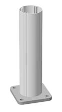

127 POLES & BASE PLATE
OPTIMAST SIGN POLES)
168 POLES & BASE PLATE
219 POLES & BASE PLATE CODE
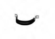
HEAVY DUTY 2-BOLT ‘D’ BRACKETS (FOR OPTIMAST SIGN POLES)
244 POLES & BASE PLATE CODE
HEAVY DUTY 2-BOLT ‘D’ BRACKETS (FOR OPTIMAST SIGN POLES)
127 ANCHOR CRADLE
SOCKETS
SOCKETS
219 ANCHOR
SOCKETS
Sign installation must take place immediately after the mast has been installed.
The Optimast heavy duty 2-bolt D brackets with rubber insert, M10 x 50T bolt and nut must be used when attaching the sign.
When the sign is mounted in the current position, the fixings are to be tightened to the correct torque settings of 18 Nm.
We advise threads to be lubricated with Rocal anti-seize stainless lubricant or similar.
1.1 Excavate the hole
For multi-pole installations, start with the pole closest to the curb.
Foundations should be excavated to a minimum diameter of 400mm1 and a depth equal to the ground sleeve length.
Remove all loose debris from the footing before pouring concrete.
1.2 Pour concrete
Concrete must be a minimum strength of 28Mpa.
Pour 100mm of concrete into the footing then bed the sleeve base into the centre of the footing, ensuring the embedment depth line is at ground level. The top of the sleeve will be 50-90mm above ground level, depending on sleeve size.
The trilobular locking bolts must face the oncoming traffic.
Ensuring the sleeve remains perpendicular and centred with a spirit level, pour concrete around the sleeve to the embedment depth line.
The ground sleeve may float vertically up during this concrete pour. To prevent this, maintain downward pressure on the sleeve to ensure the correct position is maintained above ground.
Once the kerbside sleeve is in place, repeat the process with the remaining sleeves.
Once all the sleeves are installed, cover and leave concrete to cure for 24 hours.
2.1 Pole inser tion
Line up the flute patterns of both the ground sleeve seal and aluminium pole, then push the ground sleeve seal approximately 10mm over the base of the aluminium pole (the end closest to the pre-cut post restraint bolt holes).
Align the seal flange with the locking bolts, then slide the pole into the ground sleeve. The ground sleeve seal will slide up the pole into the correct position once the pole reaches the base of the ground sleeve.
Ensure the restraint holes in the ground sleeve line up with the corresponding post restraint bolt holes in pole.
The correct placement will also result in the pole shear holes aligned to the post restraint holes in the sleeve.
2.2 Transition shoe insertion
Inser t the transition shoe by lifting the aluminium pole 100m out of the ground sleeve and insert the transition shoe so that the lip is sitting flush with the top of the ground sleeve and on top of the locking bolts.
Lower the aluminium pole back into the ground sleeve, lining up the centre groove in the transition shoe with a flute in the aluminium pole.
This will ensure the transition shoe is a snug fit between the ground sleeve and aluminium pole.
2.3 Retention bolt assembly installation
Place a nylon washer onto the M12 stainless steel bolt head and insert the bolt through the hole to the other side of the ground sleeve.
Locating the thread end of the bolt, fit a nylon washer & kinmar lock nut onto the thread and tighten to 10-12 Nm torque with the kinmar socket.
2. ALUMINIUM POLE INSTALLATION (cont.)
2.4 Fasten transition shoe & insert shear hole bung plugs
Using the trilobular spanner or trilobular key, tighten the sleeve locking bolts to 10-12 Nm torque.
Push both bung plugs into the pre-cut shear holes located on each side of the fluted aluminium pole and just above the ground sleeve seal.
3. INSTALL THE SIGN ONTO ALUMINIUM POLE ASSEMBLIES
Cut aluminium poles to required size.
Fit poly caps to aluminium poles.

NB. Drawings are not to scale, and used for illustrative purposes only.
1.1 Excavate the trench
Using suitable equipment, excavate the trench to the dimensions specified by the independent scheme designer.
1.2 Secure anchor cradles
The anchor cradle must be securely suspended in the foundation in its final position.
Level and align prior to concreting the foundation. This is usually achieved by nailing or screwing the template board to timbers spanning across the excavation or the foundation shuttering.
The underside of the removable template board is to be set to the top of concrete level. The template board should be checked with a spirit level to ensure it is level and the arrangement checked to ensure it is robust and rigid before concreting.
1.3 Pour concrete
Anchorages and baseplates of the masts should be exposed and not buried under soil. The top of the concrete foundation should be level or not more than 50mm above the surrounding ground or paving to prevent the underside of errant vehicles catching on the concrete before hitting the sign mast in a vehicle impact. The concrete must be mechanically vibrated to ensure that all air pockets and voids are eliminated from the foundation concrete.
Signfix recommends minimum concrete grade of 28MPa. However, the final design is the responsibility of the scheme designer.
Immediately after concreting the bolt position the alignment should be re-checked to ensure the anchor cradles have not moved.
The template boards may be removed the day after concreting but the temporary/disposable bolts should be retained to protect the anchor socket threads until the sign mast can be erected.
Masts and sign plates should not be erected until the contractor is satisfied the concrete has reached a cube strength of 28MPa. To erect masts earlier after concreting, stronger concrete can be used to shorten the time needed to achieve the 28MPa cube strength.
2.1 Inser t foundation studs into anchor cradle socket
Remove any debris from around the anchor and check the concrete for high spots that may prevent the mast from seating correctly on the bolts.
Remove and dispose of the temporary/disposable bolts and the template board.
Grease anchor studs and the internal threads of the anchorage sockets threads with Rocol anti-seize stainless lubricant or similar.
Screw the 4 studs by hand into the anchor socket as per the table below.
Bolt insertion depths:
Mast Type Stud DiameterLength in socket
127M16 32mm
168M20 40mm
219M20 40mm
244M24 48mm
Maximum height of exposed thread:
Mast Type Stud DiameterExposed thread length
127M16 104mm
168M20 116mm
219M20 116mm
Length in socket
244M24 137mm Exposed thread length
2.2 Fitting the Optimast
Screw one stainless steel nut down each stud until they lock tight onto each socket in the concrete. Tighten each nut with a spanner but do not apply excess torque, this will prevent the stud from turning during subsequent operations.
Screw a second stainless nut down onto each stud until they are all approximately 3 mm above the first nut. Check across all four second stainless nuts with a spirit level and adjust by screwing up or down until all four nuts are precisely level to create a level bed for the mast base plate.
Apply to each stud a stainless-steel washer.
Lower the mast onto the studs, taking care not to damage the threads.
2. ERECTION OF THE OPTIMAST ONTO THE ANCHOR CRADLES (cont.)
2.3 Securing the Optimast
Apply a stainless-steel washer to each stud, then a third stainless steel nut and hand-tighten. Check the base plate is fully seated on all four studs and the mast is vertical. If not, slacken off third stainless steel nut and adjust the nuts under the baseplate. Hand-tighten the nuts on top again and re-check.
When you are satisfied that the mast is vertical and fully seated, tighten the third stainless steel nut to the recommended torque using a torque wrench. See below table for torque settings.
The nuts below the baseplate should be checked to ensure they do not rotate and if necessary, an open ended spanner should be used to prevent any rotation.
Apply a fourth stainless steel nut to each stud and tighten to the torque recommended using a torque wrench. See below table for torque settings.
Screw the first stainless steel nut touching the concrete/socket up against the second stainless steel nut under the base plate and firmly tighten with an open ended spanner.
Re -check the mast is vertical using a suitable measuring device.
Regions are marked with the letters A (A0 to A5), B1, B2, C an D. Coastal region boundaries are smooth lines set in from a smoothed coastline bu 50, 100, 150 and 200 km. Islands within 50 km of the coast are designated in the same region as the adjacent coast.


Signfix Australia is a division of Delnorth Pty Ltd ABN 26 051 954 977.
The Signfix system was originally pioneered in England in 1979 and has since become a world leader in developing quality fixing systems to the sign industry. Signfix was established in Australia as a major supplier of sign fixing systems 20 years ago. Its products are approved by government road transport and infrastructure departments nationwide.
Our aim is to provide and maintain the highest standard of road safety with emphasis on continuous improvement of product through innovation and development.
SUPPLIERS TO
For further information visit www.signfix.com.au
P 1300 174 463 (1300 1 SIGNFIX)
F 02 4033 6599
E sales@signfix.com.au
63 Bonville Ave, Thornton NSW 2322, Australia