13 minute read
Digital techniques and first-principles design: Challenging electrification costs

by The PWI

AUTHOR: Garry Keenor
Garry is a chartered engineer with 28 years’ experience in railway electrification. Garry joined BR’s graduate training scheme in 1991 and since then has delivered a wide range of electrification designs on projects in the UK and overseas including major multidisciplinary projects. He has been a Contractor’s Responsible Engineer for 18 years and a Contractor’s Engineering Manager for 12 years. Garry is currently Group Engineer for Atkins and is responsible for all OLE design in the South West. He also acts as Atkins’ Technical Authority for OLE, and is the author of “Overhead Line Electrification for Railways”, a technical reference on the subject.
Advertisement
INTRODUCTION
The traditional processes for design of Overhead Line Equipment (OLE) along a newly-electrified route are driven by the volume of structures required – typically around 3500 per 100km of two track route – and the need to standardise the design outputs to maximise efficiency in construction. This is reflected in the design of the OLE layout plans and cross sections by the allocation designer; these form the backbone of the design deliverables; the designs are developed based on a set of rules – the System Design – and a catalogue of standard parts – the Basic Design.
The role of the allocation designer is to correctly interpret and apply the rules and parts, while plotting a path through the many conflicts and constraints with other railway assets, eliminating or mitigating hazards, and resolving the rules conflicts which exist even within the OLE discipline. This approach still requires care and skill on the part of the designer, but it allows OLE designs to be developed more quickly than if each structure and wire run – the section of wiring between two anchors – was designed from first principles.
As with everything in Engineering, there is a downside. The rules related to dynamic mechanical and electrical performance have been developed to provide a ‘safe space’, within which it is all but guaranteed that the resulting installation will safely and reliably perform for many years. Contrary to first impressions, OLE design on existing mainlines is highly specific to the site, responding to constraints such as overbridges, stations, junctions and lineside obstacles. Since the rules have been drawn up to apply to all scenarios – including the ‘edge cases’ – it is axiomatic that they must be conservative for many situations. To make matters worse, many of the rules were codified during the expansion of electrification in the years following World War 2, using calculation techniques bound by the limitations of log tables and mechanical calculators; and these rules have been in place ever since. Network Rail currently owns around 80 subvariants of OLE, with widely differing tensions and support arrangements; ranging from the heavy low speed exDC GE/MSW designs (which have a pre-war genesis), to modern high speed designs which meet the TSI requirements with multiple pantographs.
OLE engineers know that these rules can be conservative in some situations, but until recently lacked the means to challenge them in a structured and evidenced way. However, the high-profile cost failures of some electrification schemes during Control Period 5, plus the urgent need to decarbonise UK rail to meet the climate emergency, have provided a new impetus to revisit some of these rules using new ideas, techniques and technology to reduce electrification costs. COST REDUCTION
Network Rail and its supply chain has recognised this challenge at the highest levels, and now has a portfolio of work looking at challenging the old assumptions. Atkins is uniquely placed to meet this challenge; we have experienced OLE engineers, mechanical specialists, mathematicians, digital analysts and software developers working together to take a “first principles” approach to OLE design and performance challenges. Our trusted supply chain partner T-RIS brings additional specialist modelling and simulation skills. The techniques available to us include Finite Element Analysis (FEA), digital measurement and monitoring, signal processing, and statistical analysis, all guided by engineers with a deep understanding of how OLE works, both in theory and in practice.
SOLVING STEVENTON
Our first significant success in this space came in 2019 as part of the Great Western Electrification Programme, at Steventon Bridge. The grade 2 listed elliptical three-arch brick overbridge, built by Brunel, is only 399m from Stocks Lane level crossing. This scenario causes problems for the OLE engineer because the pantograph has a maximum rate of height change dictated by the natural inertia of the device. If the contact wire rises or falls too quickly, then the pantograph cannot follow the wire and will lose contact (when the contact wire is rising) or cause excessive wear (when the contact wire is falling). Both scenarios can in extreme cases cause dewirements. Steeper contact wire gradients generally limit the speed of electric trains for this reason.
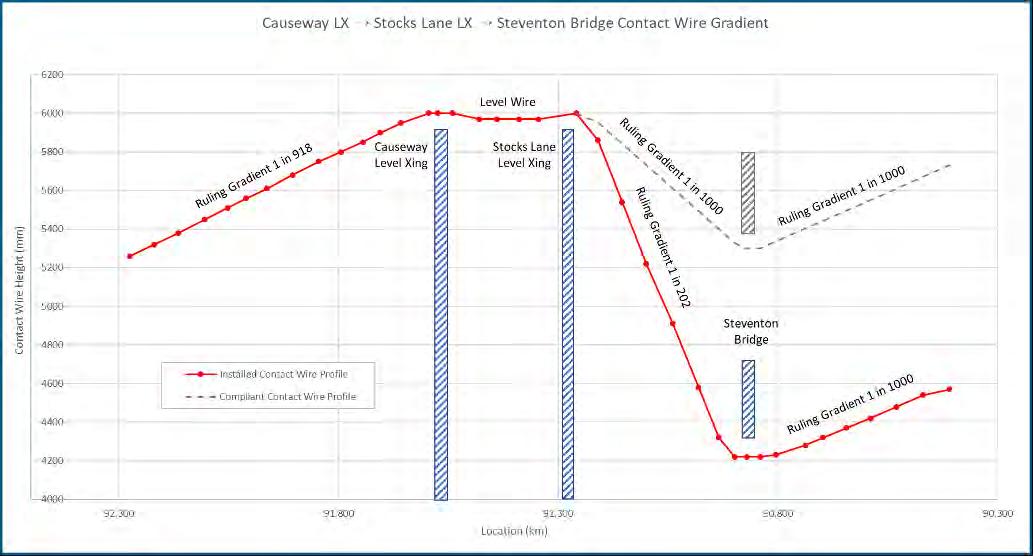
Atkins was the OLE designer at Steventon; our compliant design based on a reconstructed bridge had a contact wire gradient of 1:1000; with the rules in place stating that 1:500 was the maximum permissible. However, Network Rail had been trying unsuccessfully to gain permission to reconstruct the bridge; permission had been rejected multiple times. With the original bridge still in place, we were obliged to deliver a design with the shallowest possible gradient of 1:202 (See Figure 1). Even stretching the rules a little, this meant leaving the project unavoidably limiting electric trains to 60mph rather than 125mph. This would have had a permanent impact on the journey time for London to Bristol and Cardiff.
All involved thought that Steventon could run faster – after all, it is configured with high tension Series 1 OLE, and a fleet of modern low-unsprung-mass pantographs run on the Great Western – but neither organisation could prove it, and were unwilling to risk running a test train to find out. Network Rail therefore approached Atkins for help, and we proposed the use of our then-embryonic dynamic OLE simulation tool, D-RSS. This digital tool uses Finite Element Analysis
(FEA) techniques to build an accurate 3D model of the system, going well beyond conventional OLE modelling tools in terms of accuracy and detail. It can analyse the OLE behaviour through the bridge for a range of linespeeds and train types permitting performance predictions to be made before any trains run. Our initial modelling suggested that 110mph was possible, and gave Network Rail the confidence to undertake high speed testing. Those tests took place in traffic on 7th and 8th February 2019 (See Figure 2). The tests started at 60mph and speeds were gradually increased, with a go/ no-go decision after each run. Runs were successfully carried out at 125mph, and the results validated the model and confirmed 110mph as a safe electric train speed. All electric trains now operate through the bridge at 110mph; or, to put it another way, trains are now safely and reliably operating at 2.5 times the speed that the gradient rule would suggest is acceptable.
UPLIFT MONITORING
Another of Network Rail’s cost reduction workstreams concerns the vertical displacement of OLE bridge arms – known as uplift – at low bridges. This upward movement is a natural consequence of the contact force created by the pneumatic system on the pantograph, and must be allowed for when calculating the minimum air gap electrical clearances. As such, uplift plays a part in determining whether an overbridge has sufficient space to be electrified, or whether a reconstruction or track lower is required.
With these route clearance costs typically comprising 1/3 of the total cost of electrifying a route, every millimetre can count. The current design rule – again unchanged since the introduction of elastic bridge arms in the 1970s – is to use an allowance of 70mm, regardless of speed, OLE tension, pantograph type or any other variable. It is clear that the true uplift allowance will be lower in at least some circumstances; but without a solid evidence base, the electrical flashover risk that results from inadequate clearance is a chance we must not take.
Network Rail therefore contracted us to develop an entirely new process for monitoring and analysing OLE uplift – one which requires no permanent equipment or lengthy installation time. We took our experience of measuring deflections of bridges using Digital Image Correlation (DIC) techniques and evolved the process to
Figure 1: Compliant and installed contact wire gradients at the Steventon bridge site.
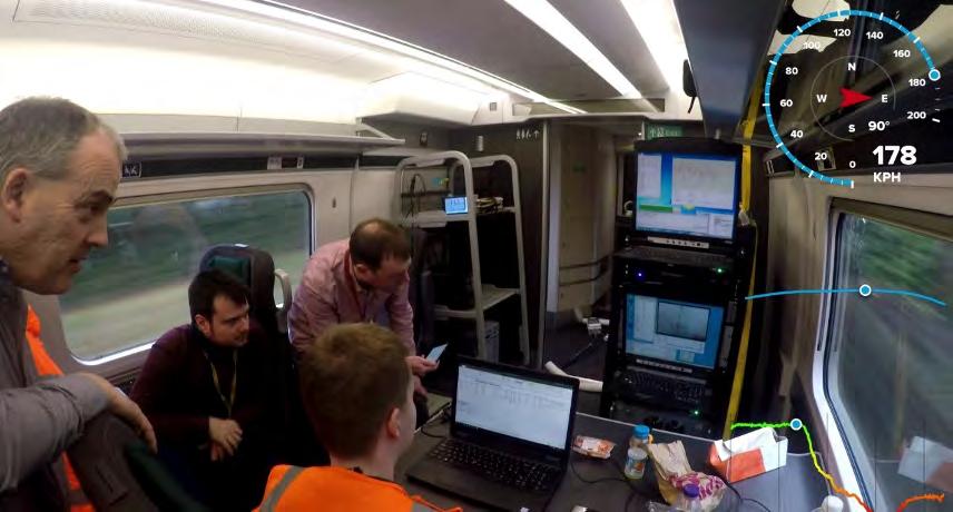
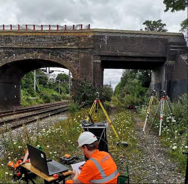
Figure 3: Digital Image Correlation (DIC) uplift measurement at Langley.
measure wire deflections. DIC is a photogrammetry technique used for accurate measurements of surface deformation and movement. The measurement process involves a simple 2-person survey at lineside, alongside the bridge to be measured - no track access is required for the work (See Figure 3). Multiple specialist video cameras on simple tripods monitor each train pass, recording video of the movement of the wire. The whole system can be set up in less than an hour, making it ideal for agile surveys at multiple sites. The video data is then analysed back at the desktop, to extract the trace of wire movement and point(s) of maximum uplift, including for trains with multiple pantographs.
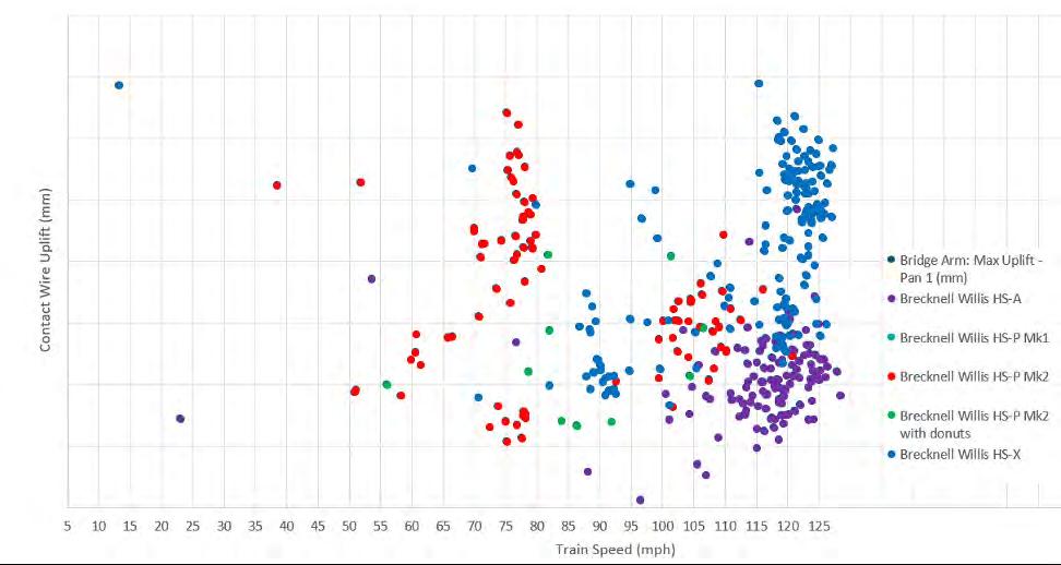
So far four sites, encompassing a wide variety of speeds, and different OLE and pantograph types, have been monitored over 12 days, providing no fewer than 750 train passages and close to 1000 individual uplifts (some trains having multiple pantographs). The data analysed so far (See Figure 4) suggests that improvements in the current uplift allowance are indeed possible. When the remaining sites have been completed in early 2021, we will have over 1000 data points, and will use statistical analysis of the results to develop a new ruleset for designers when assessing overbridge clearances. As we highlight above, bridge reconstruction costs are a primary target for cost reductions on electrification projects. Alongside the other workstreams that Network Rail has under way in this area, it also wanted to review the subject of conductor sag due to ice loading.
All OLE systems must be designed to accommodate a certain amount of additional sag due to ice accretion on the wires. This in turn increases the minimum design contact wire height to maintain minimum electrical clearances between the contact wire and the roof of passing trains, and so increases the minimum soffit height of electrified overbridges. Depending on the ice thickness and OLE span, this increase can be anywhere between 50 and 150mm.
The amount of ice to be allowed for is a complex subject – this is as much a meteorology problem as it is an engineering one, and meaningful data is hard to come by. But the more interesting question – one which Network Rail asked us to explore – was whether ice loading was being correctly applied in combination with electrical clearances.
We found that there are no formalised rules for applying sag due to ice loading at bridges. UK designers apply an approach that has informally evolved, where sag due to ice is allowed for in combination with the current national rules for minimum air gap clearances.
In order to understand why this might be incorrect, it is necessary to understand how electrical clearances are defined. The air gaps used in OLE design are not sized to withstand 25kV – rather they are sized to withstand overvoltages caused by lightning strikes. The standard voltage withstand in UK standards is 200kV.
For our study, Network Rail posed a simple question: in the UK, does lightning occur in combination with ice accretion (See Figure 5); and if not, what withstand voltage should be allowed for when icing does occur? Our answer to the first question was “if it does happen, it is extremely rare, and our standard flashover mitigations would protect against harm”. Our work on the second part of the questions showed that there is potential to reduce the overvoltage withstand to 80kV, which would result in a reduced electrical clearance requirement, and in turn reduce the required soffit height by a small, but significant, amount. Our study was presented to RSSB’s Energy Standards Committee and some positive ideas for the next steps were received. The next steps are to identify a suitable electrification project that can take the work forward and develop an appropriate standards challenge.
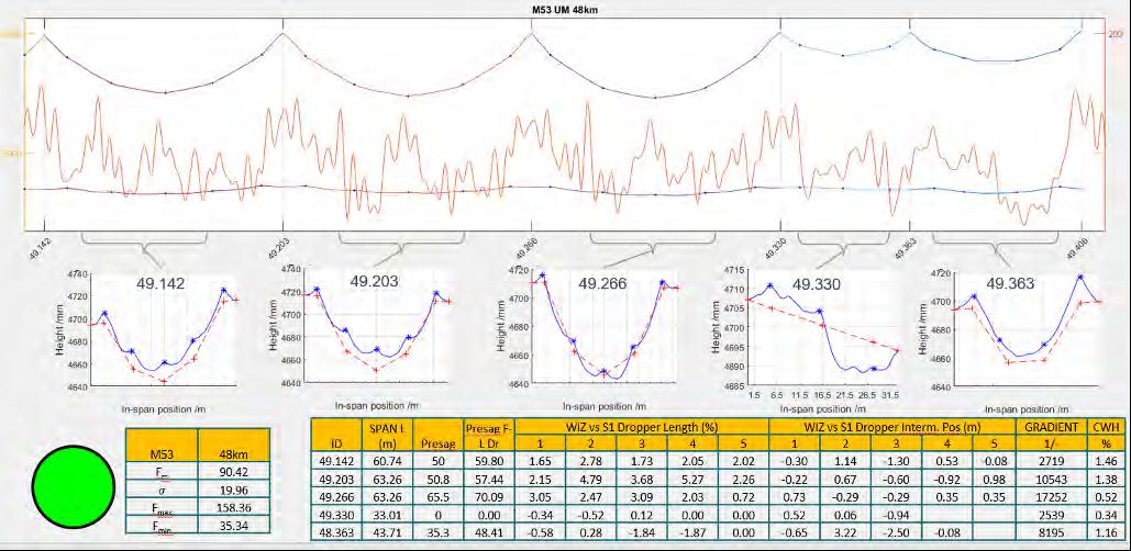
OLE StAT is another digital tool borne out of the Great Western Electrification Programme, which has gone on to a much wider deployment. It provides a method for reducing on-site OLE survey, increasing survey speed by orders of magnitude while providing high resolution as built and asset condition monitoring information. It works by analysing high frequency wire profile data collected by a train or trolley mounted device and was originally developed using a non-contact survey device mounted on a part of Network Rail’s High Output Plant System (HOPS). In a typical night shift, 50 miles of data can be gathered – the only limiting factor is measurement train speed. An example of OLE StAT output is shown in Figure 6.
Crucially, OLE StAT goes much further than conventional OLE geometry assessment tools; firstly, it uses analytical techniques to identify the entire OLE geometry, including presag, dropper position and dropper length. Secondly, it uses our unique experience of high speed test data analysis to identify those spans of OLE which are likely to perform poorly in service, due to misaligned droppers or lack of presag. It does this without reference to standards other than the TSI requirement, so deriving the acceptance criteria from the ultimate performance goals rather than the traditional installation tolerance-based approach. The tool can be used by any OLE engineer with the appropriate training to assess multiple miles of installed OLE within one working day, and has been used on both Great Western and Midland Mainline electrification, as well as on the Central Rail Systems Alliance contract where it uses New Measurement Train (NMT) outputs.
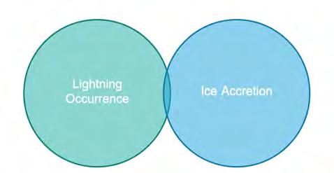
Figure 5: Potential overlap of lightning occurrence and ice accretion in UK climates.
Network Rail’s Efficient Electrification research and development programme is making great strides in addressing cost reduction, playing its part in the imperative to decarbonise in the face of the climate emergency. It would be a mistake to read this article and conclude that Atkins are undertaking all of this work; Network Rail has a number of other workstreams which show great promise, and which – in our role as OLE designer on new electrification schemes - we look forward to taking full advantage of in due course. These include:
• Developing the Voltage Controlled Clearances work undertaken at Cardiff Intersection Bridge into a national policy; • Trialling the use of insulated pantograph horns to increase safety separations between people and live parts at stations; • Benchmarking of OLE piling techniques and pile sizes; • Benchmarking of OLE structure designs; • Developing a new rationalised substation architecture for boosterless classic feeding, to minimise the number of substations required; • Overbridge Auto Transformer Feeder (ATF) design.
A further eighteen projects are in the scoping phase; space prevents them all being detailed here, but they include work on OLE span lengths, dynamic testing reduction, lightweight OLE Structures, signal screening protection, and pantograph development among others.
CONCLUSIONS
Taken together these projects represent one of the most significant reassessments of UK electrification technical policy since the switch from 1500V DC to 25kV AC in the 1950s. Atkins is engaging its unique strengths in this area to:
• Challenge and rewrite existing national rules, based on accurate data and evidence gathered using digital techniques and tools; • Develop deviations from national rules at specific locations, using a similar approach; • Use modelling to refine an existing parameter assumption at a specific location.
We continue to support these efforts, and welcome discussions with anyone who wishes to join us in achieving our aims.