


JANUARY 2020 VOL 138 PART 1 PWI ANNUAL MEMBERSHIP £82 RECEIVE 4 ISSUES OF THE JOURNAL ANNUALLY (£15.00 PER ISSUE FOR NON MEMBERS) PERMANENT WAY INSTITUTION THE PROFESSIONAL COMMUNITY FOR RAIL INFRASTRUCTURE ENGINEERING Practical Trackwork Challenge Churnet Valley Railway PAGE 22 Permanent Way Instituti o n J HTIWYENRUO SU iwpeht# 50 74 88 YOUNG ENGINEERS PWI ANNUAL CELEBRATION EVENT HERITAGE RAILWAY: UPGRADING FOR THE FUTURE THE 1
What If?
What if we showed you how we’re solving the world’s greatest challenges by transforming intangible ideas into intelligent solutions for a more connected, sustainable world? At Jacobs, we think differently about the future.

jacobs.com/whatif Follow us @JacobsConnects 2
#WhatIf
From the President
Welcome to the “new look” PWI Journal. The team have put a lot of thought and effort into the revised format so we hope you enjoy it; as always your feedback is much appreciated.


I will begin my article with an update on the Presidential initiatives that form part of our overall five-year strategic plan. We have made steady progress in arranging face to face meetings with our Corporate members and for those that have taken place, the conversation and feedback has been very valuable. Areas of importance to our Corporate members include professional registration, the need for training in certain subject areas, and some form of involvement in developing and / or assisting in competency assessments of people working on the front line. By the time this article comes to press we will have completed circa 80% of the meetings and will have started to pull together a co-ordinated response.
With respect to the work with the Sections, we have re-energised our guide on how to run a successful Section and, working alongside the respective Vice Presidents, most Sections have proposed achievable improvement plans. This includes the Glasgow Section who are trialling webinars, and the Cheshire & North Wales Section who have started running lunchtime meetings at Crewe.


This exercise has highlighted those Sections that require more assistance than others and the relevant Vice President, Stephen and I will be working to support them over the coming months. It’s important to remember that our Sections are run by volunteers with a passion for the Rail industry, shared learning and fraternity. Whilst some of our Section committee members are retired from active employment others are not and I, along with other members of the Executive team, are very grateful to the Sections for their efforts.
We are all acutely aware of the need to attract and retain a younger membership and have sought ideas from everyone we meet on how to achieve this. The graph below is a snapshot of the age profile of the membership; whilst we are attracting a younger membership it is not yet sustainable.

Outwith the Presidential initiatives there have been quite a few other occassions of note. In October we ran our third Practical Trackwork Challenge; see the detailed article on page 22, but suffice to say the feedback has been very positive. I would like to offer particular thanks to Malcolm Pearce and Roy Hickman who put their heart and soul into making the event a success.
On 12 November we held our third annual Celebration Event (see page 74), recognising all those who have achieved Professional Registration in the last 12 months. It was an absolutely joyous occasion and a delight to see Engineers achieve their potential. Our guest speaker, David Johnson gave a very thought provoking speech on what has been and still is important to him over a career spanning more than 40 years.

Finally, I would like to finish on a more sombre note. On 6 November Stephen and I represented the PWI at a Memorial Service held at Southwark Cathedral to remember all the Railway workers from Britain and Ireland who fought in World War I. It was a very moving ceremony and in the words of John Maxwell Edmunds we were reminded “For your tomorrow, we gave our today”. Joan Heery PRESIDENT Permanent Way Institution president@thepwi.org

COPY SUBMISSION DEADLINES
Illsley
Journal Production Editor
ADVERTISING ENQUIRIES Please send your enquiry to Kate Hatwell Operations Director
THE PERMANENT WAY INSTITUTION 5 Mount Crescent, Warley, Brentwood, Essex CM14 5DB
1277 230 031
PLEASE NOTE: Every care is taken in the preparation of this publication, but the PWI cannot be held responsible for the claims of contributors nor for the accuracy of the contents, or any consequence thereof. PWI ANNUAL MEMBERSHIP £82 RECEIVE 4 ISSUES OF THE PWI JOURNAL ANNUALLY (£15.00 PER ISSUE FOR NON MEMBERS) JOIN US NOW www.thepwi.org/account/register/ #thepwi thepwi.org PermanentWayInstitution @PermWayInstit Permanent Way Institution @the_pwi ISSN 2057-2425 Publishing and layout by Permanent Way Institution THE JOURNAL JANUARY 2020 VOL 138 PT 1 THE COPY SUBMISSION DEADLINE FOR OUR NEXT JOURNAL IS 15 FEBRUARY 2020 3
April 2020 DEADLINE - 15 February 2020 July 2020 DEADLINE - 15 May 2020 October 2020 DEADLINE - 15 August 2020 January 2021 DEADLINE - 15 November 2020 Please send to Kerrie
Designer &
journaleditor@thepwi.org
kate.hatwell@thepwi.org
+44
www.thepwi.org secretary@thepwi.org
With 3130 members, the PWI community has around 42,100 years of experience at our fingertips!
With 3130 members, the PWI community has around 42,100 years of experience at our fingertips!

That’s 42,100 years of meetings, night shifts, problems, successes, awards and courses!
That’s 42,100 years of meetings, night shifts, problems, successes, awards and courses!


Tap into that experience for just £82 for a whole year and connect with our ever expanding community.
Tap into that experience for just £79 for a whole year and connect with our ever expanding community.
Let’s share and gain knowledge, experience and competency together. See you soon!
Let’s share and gain knowledge, experience and competency together. See you soon!
The PWI - the professional community for rail infrastructure engineering.
The PWI - the professional community for rail infrastructure engineering.


Permanent Way Instituti o n J HTIWYENRUO SU iwpeht#
4


From the Technical Director PWI ANNUAL MEMBERSHIP £82 RECEIVE 4 ISSUES OF THE JOURNAL ANNUALLY (£15.00 PER ISSUE FOR NON MEMBERS) JOIN US NOW www.thepwi.org/account/register/ Practical trackwork challenge Churnet Valley Railway HS2 Gauging The Uniform Structure Gauge (USG) Sheffield tram train pilot One year on – lessons learnt Rail Stress due to Track-Bridge Interaction with various track and traffic conditions Heritage Railway Upgrading for the future Ballarat line upgrade Regional rail revival in Australia Overcoming logistic challenges when building large scale slab track railway projects Seminar report Worldwide High Speed Rail: The design and construction challenges from theory to operation International conferences FINE1 and OPEUS FINAL conference in Paris 21 22 34 40 50 47 52 57 62 67 International conferences Uic Nextstation conference In Iran AREMA conference 2019 in Minneapolis 68 70 TECHNICAL Learn with us OUR COMMUNITY Engage with us 3 From the President 5 Contents 6 PWI Contacts 7 From the CEO 8 Our new members and fellows 10 Section meetings 12 PWI events for your diary 14 Photos taken over fifty years apart 16 Andy2 17 Fees 81 From the Marketing and Communications Manager 82 The PWI Community 85 Thames Tunnel walk 86 A reader’s journey 88 Young engineers 92 PWI Board meeting minutes 94 Our Community - a round up of our events since the last Journal PROFESSIONAL DEVELOPMENT Grow with us 72 Professional Registration with the PWI 73 From the Registration Manager 73 Professional Registration update from Brian Counter 74 PWI annual celebration event 77 What is PWI Fellowship? 78 Training with the PWI 79 Over 90% pass rate - Training update from Brian Counter 5
CONTACTS
Engage with us
Brian Counter Technical Director technicaldirector@ thepwi.org
Andy Packham Technical Content Manager andy.packham@ thepwi.org
CENTRAL ENGLAND SECTIONS
VICE PRESIDENT Andy Packham andy.packham@thepwi.org
BIRMINGHAM SECRETARY
Timothy Atkinson timothy.atkinson@networkrail.co.uk 07719 993516
MILTON KEYNES SECRETARY
Kevin Thurlow kevin.thurlow@networkrail.co.uk 07802 890299
NOTTINGHAM & DERBY SECRETARY
John Garlick jgees01@btinternet.com 07532 071727
IRELAND SECTION
VICE PRESIDENT Pat Watchorn pat.watchorn@irishrail.ie
IRELAND SECRETARY
Joe Walsh pwiirishsection@gmail.com 00 353 872075688
NORTH ENGLAND SECTIONS
VICE PRESIDENT Phil Kirkland philkirkland@btinternet.com
NORTH EAST SECRETARY
Phil Kirkland philkirkland@btinternet.com 07899 733276
WEST YORKSHIRE SECRETARY Martin Wooff pwi@daelnet.co.uk 07487 652622
YORK SECRETARY
Gareth Dennis york@thepwi.org 07951 918236
NORTH WEST ENGLAND & NORTH WALES SECTIONS
VICE PRESIDENT Roy Hickman royhickman@live.co.uk
CHESHIRE & NORTH WALES SECRETARIES
Lynne Garner lynnegarner79@icloud.com 07494 753652

Alastair Roberts a.roberts@aegis-cert.co.uk 07768 210480

LANCASTER, BARROW & CARLISLE SECRETARY
Philip Benzie p.benzie@yahoo.co.uk 01704 896924
MANCHESTER & LIVERPOOL SECRETARY
Richard Wells richard.wells@tonygee.com 07817 302652
SCOTLAND SECTIONS
VICE PRESIDENT Mark Taylor mark.taylor5@networkrail.co.uk
EDINBURGH SECRETARY
Bob Gardiner bobrail65@gmail.com 07771 828811
GLASGOW SECRETARY
Jim Watson glasgow@thepwi.org 07590 929107
Andy Steele Technical Content Manager andy.steele@ thepwi.org
Paul Ebbutt Professional Development Officer for London, South East, South West & South Wales developmentofficer south@thepwi.org 07887 628298


Brian Parkinson Professional Development Officer for Midlands, North East, North West & Scotland developmentofficer north@thepwi.org 07876 578905
SOUTH ENGLAND & SOUTH WEST WALES SECTIONS
VICE PRESIDENT Paul Ebbutt paulebbutt1@gmail.com
CROYDON & BRIGHTON SECRETARY
Colin White c.white@chaucerrail.co.uk 07845 316042
LONDON SECRETARY Thomas Utley thomasutley@tfl.gov.uk 07885 732231
SOUTH & WEST WALES SECRETARY Andrew Wilson southandwestwales@thepwi.org 07974 809639

THAMES VALLEY SECRETARY Richard Antliff richard.antliff@gmail.com 07804 329497
WESSEX SECRETARY Kenneth Newell kenneth.newell@btinternet.com 07771 668044
WEST OF ENGLAND SECRETARY Constantin Ciobanu Constantin.Ciobanu@atkinsglobal.com 07549 319335
EXETER Mark Woollacott Mark.woollacott@networkrail.co.uk 07920 509011
INDIA SECTION
BENGALURU SECRETARY Srinagesh Rao sringagesh.rao@arcadis.com
INTERNATIONAL CONTACTS
MALAYSIA Mr K Sukumaran sukumaran@ktmb.com.my
NEW SOUTH WALES Peter Boonstra secretary@pwinsw.org.au
QUEENSLAND Robin Stevens robin.stevens@qr.com.au
SOUTH AFRICA Callie Herselman callie.herselman@transnet.net
SOUTH AUSTRALIA Mark Pronk mark.pronk@sa.gov.au
Liz Turner Registration Manager profeng@thepwi.org
6
Edgley Deputy President john.edgley@ networkrail.co.uk


From the CEO
VISIBILITY - I trust you’ll see that in addition to injecting more visual vibrancy, our new Journal content is grouped and signposted under the Institution’s three “Journey with us” themes: Engage, Learn, and Grow, so not only is the Journal even better to look at, it’s easier to navigate too! Change to the Journal reflects wider change within the Institution where new Sections, more professionally registered members, and increased industry engagement are all making the PWI more visible. Please take up the President’s invitation and let us know what you think…

STRATEGY UPDATE - In mid-November, the PWI Board agreed the Institution’s 2020 budget and endorsed the business plan that will take us to 2024. Creation of the business plan, turning the PWI’s strategic goals into a quantified five-year plan, required much effort over the Summer and early Autumn. It’s therefore appropriate to expand a little on what’s been done since the Board agreed in February 2019 its eight strategic goals and priorities for the period to 2024. Recapping, the eight goals are: i) establishing an expanded Executive team to deliver both business as usual (as a fully-fledged professional engineering institution), and strategic development; ii) enhancing the Institution’s relationship with its Corporate members; iii) upgrading the PWI website and its on-line presence; iv) developing our brand, focussing on activities that offer best value to our members; v) reviewing and strengthening the Section structure at home and overseas so that it accurately matches our current and potential membership; vi) strengthening competence management in the rail industry; vii) enhancing our high level training and development products; and viii) developing our capability as a custodian of industry technical knowledge. For each goal a series of outcomes have been defined and the first three goals are highlighted as the most pressing.
Looking at progress on the three high priority goals: firstly, establishment of the new team was completed when Technical Content Managers Andy Packham and Andy Steele were appointed in late Summer. Kerrie Illsley has taken on the role of production editor for the Journal, Liz Turner has a firm grip of professional registration, as has Michelle Mabbett for marketing. Responsibilities have been redrawn and the team has settled well into new ways of working.
A critical ingredient of our second goal is a programme of structured face to face discussions with all existing Corporate members. In her introduction, the President has already covered progress here in some detail and, thanks in significant measure to her input and drive, these discussions - the first step to achieving the goalwill be complete by the end of the first quarter of 2020.
Kate Hatwell and Michelle have made good progress on the project to replace our website, our third high priority goal. The existing PWI site was built nearly 10 years ago and requires increasing amounts of TLC and specialist support to remain active. Technology has moved on, and software is increasingly modularised and industry-standard, so development of the replacement should be relatively straightforward. Much care is being taken to ensure we procure effective and efficient “back office” functionality enabling us to give better service to a growing membership. Specification work has been completed, allowing detailed market testing to take place over the Winter.
Looking at what has been achieved to date against other strategic goals, four pieces of work stand out. The first is the work on supporting and developing Sections, described at more length in the President’s introduction. The second is the refinement of the PWI brand, visible in our “Journey with us” message and its components, in the restyling of the Journal, and in the nomination of PWI Ambassadors. The third is an analysis of the Institution’s market position, identifying current and potential relationships: once finalised this will underpin both a detailed communication plan for the Institution, and the review of our regional and Section operations. Fourthly, much valuable work has been done by Brian Counter and his technical team to bring new and highly successful training courses on-line.
So, delivery of the PWI’s strategic goals is well underway. You will see clear evidence of delivery through improvements to the way the Institution operates and in what it offers.

HOME AND AWAY - I was fortunate enough to attend the 22nd International Convention of the Working Committee on Railway Infrastructure Technology (OEVG Congress) in Salzburg in September. This was excellent (fully up to PWI standards!) with lots to learn from current Austrian, German and Swiss experience and developments. Simultaneous translation (in three languages) made it easy to follow the presentations. My only disappointment was that I was one of only two delegates from the UK. Whilst the UK can undoubtedly hold its own in the international world of railway performance and technology, we don’t yet have a monopoly on wisdom and there are still valuable lessons to be learnt.
Later in the Autumn I travelled to Germany and to Hong Kong both on rail-related business. Lessons from those trips are that the UK has a lot to offer other world railway administrations in terms of both the management of infrastructure performance and in the proper understanding of system safety risk.
AND FINALLY - A very warm welcome to our new Section and members at Exeter: a reappearance on the PWI map fully justified by the volume of infrastructure work taking place in Devon and Cornwall. Many thanks to Mark Woollacott and his colleagues for taking the initiative and following through.


 John
Stephen Barber CEO Permanent Way Institution stephen.barber@thepwi.org
John
Stephen Barber CEO Permanent Way Institution stephen.barber@thepwi.org
Michelle Mabbett Marketing Manager michelle.mabbett@ thepwi.org
Kate Hatwell Operations Director kate.hatwell@thepwi.org
Illsley Designer & Journal Production Editor journaleditor@thepwi.org Marketing Assistant kerrie.illsley@thepwi.org
Sara Green Membership Secretary secretary@thepwi.org
Kerrie
Nick Millington Deputy President nick.millington@ networkrail.co.uk
Stephen Barber Chief Executive Officer
stephen.barber@ thepwi.org
Andy
Non-Executive Director mrandrewjcooper@ gmail.com Colin Wheeler Non-Executive Director cj.wheeler@ btinternet.com Andy Tappern Non-Executive Director andy.tappern@ networkrail.co.uk
Non-Executive Director jcdutton@btinternet.com 7
Joan Heery President president@thepwi.org
Cooper
John Dutton
New members
We’re honoured to have you on board and are thoroughly looking forward to working with you.
We’ll keep you updated on news and events via our monthly newsletter as we don’t want you to miss a thing. We have a thriving social media network and we’d love to see you get involved! We’re here to help and so if you have any questions, then shout out!

NEW MEMBERS
Bengaluru - Mohammad Tamseel Zaman, Suresh Alagarsamy
Birmingham - Sara Ali, Mukhammad Amrozi, Kofi Ackah, Karan Patel, Jordan Carpenter, Zane Sewell, Leah Wilks, Khushbukht Alia, Arnaud Lizet, Spencer Senda, Kamil Khalikuzzaman, Joo Chin, Navin Nair
Cheshire & North Wales - Matt Graham
Croydon & Brighton - Ryan Looker, Ronald Gilgeours
Edinburgh - Mark Williamson, Konstantin Popov
Glasgow - Craig McLaughlin, Darren Johnstone, Saqib Siddique, Lee Kirk, Stuart Colvin, Michaela Silver-Woods
International - Kin Ho Wan, Eugene Okosun, Mark Fowler, Mohd Afiq Mohd Sabri, Aleksandar Urosevic, Paul Newman
London - William Hoare, Viji Uthayakumar, Melih Akbay, Ricky Prescott, Jason Lund, Matthew Teller, David Gardner, George Woollard, David Vincent, Charlton Fernandes, Shaun Jinks, Om Prakash Singh, Bethany Williams-Thomas, Adam Kopiczko, Ayodeji Adebanjo, Mohammad Najmul Hasan, Prashant Alluri, Tristan Debski, Olubobola Ijausi, Luke Boggis, Tolib Ayoola, Michael Polley
Manchester & Liverpool - Joe Whittle, Elaine Yip, Joshua Yates, Liam Williams
Milton Keynes - Mark Ward, Bleddyn-James Davies, Niall Greenstreet
North East - Michael Telford, Brandon Robe, Tia-Louise Jones, Daniel Cunningham, Nicole Figliola
Nottingham & Derby - Liam Pacey, David Greenwell, Matt Parkin, Iain Millington, James Douglas
South & West Wales - Kevin Lakey, Adrian Crees, Scott Aston, Matthew Field
Thames Valley - Simon Warren, Ian Young, Michael Zeidler
West of England - Austin Hodges, Michael Payne, Steven Barrett, Alexander Day, Helen Warren
West Yorkshire - Ionut Morosanu, Christopher Bycroft
York - John Walsh, Elliott Goulding, Christopher Middleton, Jack Gaffney, Michael Stacey, Amy Bailey, Naveed Akhtar, Emma Logan
FELLOWSHIPS
Peter Dearman – North East Steve Hooper – International Brian Paynter – South & West Wales
8
We are including a PWI membership form in this Journal. This way, you have it at your disposal to introduce any friends, family or colleagues to the PWI who you think might be interested in joining.


Remember, we are an inclusive Institution, which means we welcome anyone to join us who is interested in rail. From track professionals to train enthusiasts, we are a community of like-minded individuals who love to think, talk and learn about engineering in this field.

If you know someone like that who is not already a member, please encourage them to join us. 2020 is all about growing our community, and we would love you to be involved in that.

¬ tolerates vertical track position changes ¬ no bearing on the sleeper surface ¬ installation is possible without any machinery ¬ in combination with the 1,200 mm STRAIL inner panels > increased position stability and suitable for maximum loads ¬ pontiSTRAIL 713 and STRAIL outer panels use the same kerbstone > easy exchange for higher loads STRAIL (UK) Ltd. - Richard Whatley Tannery Lane // Send / Woking // GU23 7EF // Great Britain // Phone +44 (14 83) 22 20 90 // Fax + 44 (14 83) 22 20 95 // richard@srsrailuk.co.uk THE EXTRA STRONG SYSTEM FOR MAXIMUM LOADS pontiSTRAIL - aluminum bearer and rubber panel, a combination for highest demands.
get recruiting!
Let’s
Like no other.
Be part of a professional community.
PWI ANNUAL MEMBERSHIP £82 RECEIVE 4 ISSUES OF THE PWI JOURNAL ANNUALLY (£15.00 PER ISSUE FOR NON MEMBERS) JOIN US NOW www.thepwi.org/account/register/ 9
2020 is all about growing our community, and we would love you to be involved in that.
Section meetings
Response Codes (QR codes) are little blocky, black and white squares of digital information that take the user to an app or webpage on their smartphone, like magic. Kind of.

They are simply a type of two-dimensional barcode that can only be read using smartphones or other devices that are dedicated to QR reading.


Denso-Wave (a subsidiary of the Toyota Group) are credited with the invention of the QR Code as early as 1994. Although QR code was initially intended to be used to track parts in the automobile industry, its use has greatly grown ever since.
There are lots of ways to use QR codes, but for this Journal we’re using them to help you find further information on our website and in particular the codes on this page will take you directly to the Section page on the website where you’ll find useful meeting information such as locations, meeting details and easy ways to book.
We simply want to make things easy for you and hopefully these funny looking little blocks will do just that.
Most smartphone cameras are clever enough to recognise the code but some phones may need you to you install a dedicated QR reader app; just search your app store for a QR reader, any will do the job. I’d recommend trying your camera first for ease, here’s how…


If your camera is clever enough to recognise the code, target handles will appear around the code and you should see a request to open the targeted webpage, select yes.
Open the camera on your smart phone and hold it over the QR code as if taking a photograph of it. If your camera is clever enough to recognise the code, target handles will appear around the code and you should see a request to open the targeted webpage, click select.
If your camera doesn’t play ball, simply download a QR reader app. Open the app and follow the instructions, they are generally very easy to follow. Should you get stuck, drop me a line (please note that I am not an IT guru by any means, but I’m happy to help).
Kerrie Illsley Marketing Assistant, Designer & Journal Production Editor kerrie.illsley @thepwi.org
PWI Section meetings are great places to learn about rail projects, new technical developments and network with other rail professionals.
10
We hold over 200 meetings a year and we want to make the process of finding a meeting easy for you, so we’d like to introduce QR codes.
Drum roll please.
IRELAND
The
The
The
SOUTH
EDINBURGH
LONDON
EXETER
WESSEX
The
The Eastleigh Railway Institute, SO50 9FE
Network


NORTH EAST
Newcastle College Rail Academy, NE10 0JP WEST YORKSHIRE
The Cosmopolitan Hotel, LS1 4AE
YORK Network Rail Meeting Rooms 0.1, George Stephenson House, YO1 6JT
The Scots Guards Club, EH12 5DR
GLASGOW WSP Offices, 7th Floor, G1 3BX
Ashling Hotel, D08 K8P5
Prince of Wales Hotel, N37 T2P0
Brookfield Suite, BT1 3LP
& NORTH WALES
Town Crier
6DN
BARROW & CARLISLE Station Hotel, PR1 8BN Royal Station
LA5 9BT Network Rail, CA28 6AX Network Rail, CA1 2NP
Floor, Network Rail,
2ND
& BRIGHTON Mott MacDonald
CR0 2EE
MANCHESTER & LIVERPOOL Manchester Metropolitan University, Room E0.05, M1 5GD CHESHIRE
The
Inn, CH1 3AE Crewe Arms Hotel, CW2
LANCASTER,
Hotel,
BIRMINGHAM 2nd
Baskerville House, B1
NOTTINGHAM & DERBY Aston Court Hotel, DE1 2SL Jury’s Inn Hotel, NG2 3BJ MILTON KEYNES Auditorium, The Quadrant, MK9 1EN CROYDON
House,
10th Floor, London Underground, SW1H 0BD
Transport for London, E20 1JN
&
WALES
Rail
WEST
Network
Offices, CF10 5ZA
Rose and Crown, SE1 8DP
Rail Offices, Waterloo Station, SE1 8SW THAMES VALLEY Network Rail Offices, Davidson House Offices, RG1 3EU
1DW
WEST OF ENGLAND Engine Room, Atkins, SN1
BENGALURU ARCADIS
simply want to make things
you and
these
will
that.
will
you
where you’ll
locations,
details
SEZ Office Bengaluru, Karnataka 560045, India We
easy for
hopefully
funny looking little blocks
do just
Codes on this page
take
directly to the Section page on the website
find useful meeting information such as
meeting
and easy ways to book.
NEW SECTION!!! 11
Network Rail, Training Room, Central Station Buildings, Queen Street, Exeter, EX4 3SB
PWI events for your diary
FEBRUARY - APRIL 2020
Section meetings and social events Seminars, exhibitions and site visits
Training courses, professional registration workshops, professional review interviews and Journal article deadlines
FEBRUARY 2020
4 February
SECTION MEETING - NORTH EAST
Aspects of Railway Safety (Chris Hext, Director Safety, Powerlines Group). Newcastle College Rail Academy, William Street, Felling, Gateshead, NE10 0JP.
4 February
SECTION MEETING - WESSEX
London Overground: History and Developments (David Mansfield, Rail for London). Upper Room, The Rose and Crown, Columbo Street, Waterloo, London, SE1 8DP.
5 February
SECTION MEETING - THAMES VALLEY
Level Crossings; Suitable and Sufficient Risk Assessment (Andrew Allen, Senior Engineer, Aegis Certification Services). Network Rail Offices, Davidson House, Forbury Square, The Forbury, Reading, RG1 3EU.

6 February
SECTION MEETING - CHESHIRE & NORTH WALES Northern Powerhouse Rail: Delivering a Vision (Tim Wood, Rail Director, Northern Powerhouse Rail). Crewe Arms Hotel, Nantwich Road, Crewe, Cheshire, CW2 6DN.
6 February
SECTION MEETING - MILTON KEYNES
Saudi Railway 50 degrees (Fraser Todd and Andrew Turner, Network Rail). Auditorium, The Quadrant, Network Rail, Elder Gate, Milton Keynes, MK9 1EN.
6 February
SECTION MEETING - EDINBURGH
High Speed Handbacks of Track Renewal Sites (John Oates, Professional Head of Track and Design, Babcock International Group). Upstairs Function Room, The Scots Guards Club, 2 Clifton Terrace, Opposite Haymarket Station, Edinburgh, EH12 5DR.
10
February
SECTION MEETING - SOUTH WALES
Infrastructure Asset Transfer for South Wales Metro (Colin Brading, Transport for Wales). Network Rail Offices, St. Patrick’s House, Curran Road, off Penarth Road, Cardiff, CF10 5ZA.
12 February
PROFESSIONAL REGISTRATION WORKSHOP - EXETER
FREE! Booking Essential! Please contact Paul or Mark. Paul Ebbutt 07887 628298 developmentofficersouth@thepwi.org Mark Woollacott 07920 509011 Mark.woollacott@networkrail.co.uk
Network Rail, Training Room, Central Station Buildings, Queen Street, Exeter, EX4 3SB.
12
February
SECTION MEETING - GLASGOW
Future of Rail Competition: REF Scotland Sloans Restaurant, Cranston House, 108 Argyle Street, 62 Argyle Arcade, Glasgow, G2 8BH.
12 February
SECTION MEETING - LONDON London Bridge (Jonathan Wright, Balfour Beatty). 10th Floor, London Underground, 55 Broadway, London, SW1H 0BD.
12 February
SECTION MEETING - NOTTINGHAM & DERBY Mind the Gap - Managing ‘The Platform Train Interface’ (Professor Bridget Eickoff, University of Birmingham and RSSB) Jurys Inn Hotel, Station Street, Nottingham NG2 3BJ.
13 February
SECTION MEETING - BIRMINGHAM Derailment Risk at Facing Switches (Andy Franklin, Principal Project Engineer, Network Rail). 2nd Floor, Network Rail, Baskerville House, Broad Street, Birmingham, B1 2ND.
15 February
JOURNAL DEADLINE - Please send articles to journaleditor@thepwi.org
18 February
SECTION MEETING - LANCASTER, BARROW & CARLISLE Track and Structures Maintenance on the Talyllyn Railway (David Ventry, Talyllyn Railway). Station Hotel, Butler Street, Preston, PR1 8BN.
19 February
SECTION MEETING - GLASGOW East Kilbride Capacity Enhancements (Tom Wilson, WSP, Glasgow). WSP Offices, 7th Floor, 110 Queen Street, Glasgow, G1 3BX.
26 February
SECTION MEETING - WEST OF ENGLAND
Eddy Current/PLPR (Speaker TBC). Engine Room, Atkins, 5th Floor Milford House,1 Milford Street, Swindon, SN1 1DW.
MARCH 2020
3 March
SECTION MEETING - WESSEX
Confidential Reporting (CIRAS) (Speaker TBC). Network Rail, Basingstoke Campus, Gresley Road, Basingstoke, RG21 4FS.
4 March
PWI NORTH WEST TECHNICAL SEMINAR Booking Essential! Utilising New Technology on Railways Manchester Conference Centre, Sackville Street, Manchester, M1 3NJ.
4 March
SECTION MEETING - THAMES VALLEY
Cardiff Intersection Bridge: Part 2 (Phil Holbourn, Holbourn Engineering Ltd and Network Rail). Network Rail Offices, Davidson House, Forbury Square, The Forbury, Reading, RG1 3EU.
5 March
SECTION MEETING - MILTON KEYNES
TIGER (Ian Barber, Network Rail). Auditorium, The Quadrant, Network Rail, Elder Gate, Milton Keynes MK9 1EN.
5 March
SECTION MEETING - EDINBURGH
Composite Components at Newark Flat Crossing (Phil Winship, Principle Engineer, Network Rail). Upstairs Function Room, The Scots Guards Club, 2 Clifton Terrace, Opposite Haymarket Station, Edinburgh, EH12 5DR.
12
5 March
PROFESSIONAL REVIEW INTERVIEWS
The Priory Rooms, Quaker Meeting House 40 Bull Street, Birmingham, B4 6AF. Your completed application form and Professional Review Report must reach us at least six weeks prior to the interview date.
9 March
SECTION MEETING - SOUTH WALES
Cardiff Intersection Bridge: Part 2 (Phil Holbourn, Holbourn Engineering Ltd and Network Rail). Network Rail Offices, St. Patrick’s House, Curran Road, off Penarth Road, Cardiff, CF10 5ZA.
9 March
SECTION MEETING - LONDON Asset Protection - the protection of Network Rail assets interfacing with outside parties (Mona Sihota, Network Rail) and Section AGM 10th Floor, London Underground, 55 Broadway, London, SW1H 0BD.
11 March
SECTION MEETING - EXETER Works Delivery So Far (Speaker TBC). Network Rail, Training Room, Central Station Buildings, Queen Street, Exeter, EX4 3SB.
18 March
SECTION MEETING - NOTTINGHAM & DERBY The History of CWR and Hot Weather Management (Andy Franklin, Principle Project Engineer Lineside and Track, Network Rail). Aston Court Hotel, Midland Road, Derby, DE1 2SL.
18 March
SECTION MEETING - GLASGOW Glasgow Subway Improvements (John Campbell, SPT, Glasgow) and Section AGM. WSP Offices, 7th Floor, 110 Queen Street, Glasgow, G1 3BX.
25 March
SECTION MEETING - WEST OF ENGLAND Cardiff Intersection Bridges: Part 2 (Phil Holbourn, DPE Route Section 9 (Open route and CIB) Project Engineer (Track), Network Rail). Engine Room, Atkins, 5th Floor Milford House, 1 Milford Street, Swindon, SN1 1DW.
APRIL 2020
1 April
SECTION MEETING - THAMES VALLEY In-Possession Approvals of Rail Plant (Sam Barrett, Senior Engineer, Aegis Certification Services). Network Rail Offices, Davidson House, Forbury Square, The Forbury, Reading, RG1 3EU.
2 April
SECTION MEETING - CHESHIRE & NORTH WALES Acton Grange Junction Design and Construction Challenges and Lessons Learnt (Chris O’Keefe, Network Rail). Crewe Arms Hotel, Nantwich Road, Crewe, Cheshire, CW2 6DN.
2 April
SECTION MEETING - MILTON KEYNES Kuranda Scenic Railway (Gareth Evans, Network Rail). Auditorium, The Quadrant, Network Rail, Elder Gate, Milton Keynes MK9 1EN.
2 April
SECTION MEETING - EDINBURGH “Mind the Gap” - Gauging (Rob Lacey, Principle Engineer, Network Rail). Upstairs Function Room, The Scots Guards Club, 2 Clifton Terrace, Opposite Haymarket Station, Edinburgh, EH12 5DR.
6 April
SECTION MEETING - SOUTH WALES Train-Track Recording (Kevin Hope, Network Rail). Network Rail Offices, St. Patrick’s House, Curran Road, off Penarth Road, Cardiff, CF10 5ZA.
7 April
SECTION MEETING - NORTH EAST Mechanised Maintenance Update (Tim Stafford, Robel (UK) Ltd). Newcastle College Rail Academy, William Street, Felling, Gateshead, NE10 0JP.
8 April
SECTION MEETING - LONDON Techs Factor Competition. 10th Floor, London Underground, 55 Broadway, London, SW1H 0BD.
14 April
SECTION MEETING - LANCASTER, BARROW & CARLISLE Far North Track Maintenance Partnership (Jamie MacPherson, Stobart Rail) and Presidential Visit (Joan Heery, President, PWI). Network Rail, North Shore Road, Whitehaven, CA28 6AX.
15 March
SECTION MEETING - GLASGOW Sustainable Infrastructure Renewals (Brian Beck, Network Rail, Glasgow). WSP Offices, 7th Floor, 110 Queen Street, Glasgow, G1 3BX.
15 April
SECTION MEETING - EXETER Gauging the Western (Speaker TBC). Network Rail, Training Room, Central Station Buildings, Queen Street, Exeter, EX4 3SB.
21 April
SECTION MEETING - WEST YORKSHIRE Overhead Traction Electrification: Energy Efficiency and Decarbonisation delivered (Peter Dearman, Network Rail). The Pullman Room, The Cosmopolitan Hotel, 2 Lower Briggate, Leeds, LS1 4AE.
23 April
SECTION MEETING - NOTTINGHAM & DERBY Derailment Investigation (Dr Mark Burstow, Principle Vehicle Track Dynamics Engineer, Network Rail) and Section AGM. Aston Court Hotel, Midland Road, Derby DE1 2SL.
28
April
PWI SCOTLAND TECHNICAL SEMINAR Booking Essential!
Electrification: Delivering the business case Glasgow Royal Concert Hall, 2 Sauchiehall Street, Glasgow G2 3NY.

NOTES FOR THE REST OF 2020
INFRARAIL 12-14 May 2020
Stand C03 Olympia London, W14 8UX
BOOKING OPEN LATE JANUARY: www.infrarail.com

PWI TECHNICAL SEMINAR - ON TRACK FOR A SAFER RAILWAY 20 May 2020 (See page 56)
RAIL LIVE 17-18 June 2020
Stand J3, Quinton Rail Technology Centre, CV37 8RP BOOK HERE: www.raillive.org.uk
PROFESSIONAL REVIEW INTERVIEWS
11 June 2020, 173-177 Euston Rd, London NW1 2BJ 16 Sept 2020, 173-177 Euston Rd, London NW1 2BJ 16 Dec 2020,173-177 Euston Rd, London NW1 2BJ
Professional Review Reports must reach us at least six weeks prior to your preferred interview date.

TRAINING - PWI TRACK ENGINEERING DIPLOMA 8 - 11 June 2020 MODULE 1 20 - 23 April / 21 - 24 September 2020 MODULE 2 11 - 14 May / 9 - 12 November 2020 MODULE 3 (See page 78)
TRAINING - TRACK RENEWAL, PLANNING & DRAINAGE 15 - 18 June 2020 Part A 29 June - 2 July 2020 Part B (See page 78)
TRAINING - S&C REFURBISHMENT 6 - 8 October 2020 Part A 20 - 22 October 2020 Part B (See page 78)
JOURNAL COPY SUBMISSION DEADLINES
April 2020 Issue, Deadline 15 February 2020
July 2020 Issue, Deadline 15 May 2020 October 2020 Issue, Deadline 15 August 2020 January 2021 Issue, Deadline 15 November 2020
PWI TECHNICAL SEMINAR - PLANT AND MACHINERY TO SUPPORT RAIL INFRASTRUCTURE RENEWAL AND MAINTENANCE FOR THE 2020S AND BEYOND Late autumn 2020 (See page 102)
Attending events counts towards your CPD. So does writing an article for the Journal! thepwi.org PermanentWayInstitution @PermWayInstit Permanent Way Institution @the_pwi Hashtag your photos! #thepwi www.thepwi.org/calendar/ To view every event in the online calendar, filter by UPCOMING EVENTS 13
Photos taken over fifty years apart demonstrate the uniqueness of the PWI community
On page 22 you will find our technical piece about this year’s Practical Trackwork Challenge (PTC), where rail professionals who have little site experience participate in ballasting and track laying activities on a live site, using both traditional and current methodology, with opportunities to enhance their knowledge and appreciation of the constituent elements of such work. This year was the third of its kind and saw the installation of 250m of ballasted plain line on existing formation at Leekbrook on the track near Leek Brook Station on Churnet Valley Railway.
When we reviewed the photos taken at the event, we came across this great image that bears an uncanny resemblance to a black and white still from the PWI archives, taken in 1965, featuring our key PTC organiser Malcolm Pearce at the age of 25. In both photos, the teams are manually aligning chaired sleepers or baseplated S&C timbers in readiness for the installation of rails or S&C units and rails, in both cases using similar traditional, but still relevant, manual methods.
Viewing the photos side by side, that have been taken over fifty years apart, really demonstrates the uniqueness of the PWI community. Honorary PWI Fellow Malcolm Peace is a fine example of the careerlong transition from budding professional to established expert, and how that transition is supported by the PWI in terms of learning, training and community.
Malcolm further demonstrates the motivation and dedication of our members when they reach such levels of expertise, to feed their knowledge back into industry and our community, for our newer members to absorb. This continuation of knowledge and experience being learnt, refined and shared over decades of time is what makes the PWI community and offering to industry so special.
PWI members are motivated to help each other and invest back into the railway. While there is indeed a constant influx of new technology, there are still fundamental tasks that need to be done - and done well - and this is where personal experience and wisdom is imperative. Those at the start of their career, while contributing fresh ideas and outlooks, can benefit from the experience and wisdom of those who have already been there, done that and got the T-shirt, who in return can enjoy the enthusiasm of the ever-evolving community.
Pictured left are delegates of the 2019 Practical Trackwork Challenge.
Malcolm is pictured right (centre) aged 25 at Ambergate West Junction in 1965.

14
Because of the way that the technical and practical engineering functions are set up and managed on today’s UK rail network, few engineers have the opportunity to take track and associated infrastructure projects through specification, survey, design, planning, setting out, installation and handback in the manner in which contemporaries and myself were trained to do from the early stages of our careers.

The PTC aims to give young railway industry engineers who only have experience in specific functions an appreciation of all the processes that make up a complete project. The event is carried out on a live site, with the opportunity for hands-on participation and to observe specialist OTP, OTM and equipment carrying out a wide range of track and formation processes.
The young engineers, working in teams, are managed, supervised and mentored by experienced railway track and infrastructure engineers throughout two full days of site work and two evenings of theory and discussion. They are encouraged to take full advantage, either in groups or individually, of the expertise available to them at any time throughout the event.
MALCOLM PEARCE
It was invaluable to meet people with a huge range of experience and knowledge.
Leading experts of the industry took a lot of time and effort to train us. It is great to know that they are willing to share their knowledge. Thank you.
DELEGATE FEEDBACK
15
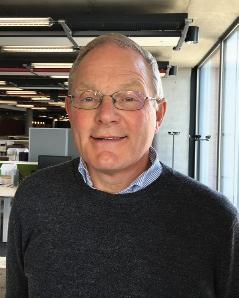
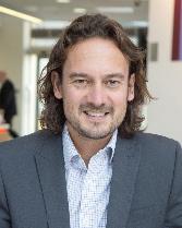
In 2019 the PWI created the role of Technical Content Manager (TCM) and after a competitive process, appointed us - Andy Steele (left) and Andy Packham (right) to carry out the role on a job share basis. In future Journals, we will be writing a short column “Andy Squared” giving our viewpoints on the many subjects and issues that are relevant to constructing, maintaining and renewing railway infrastructure in the 21st Century (not forgetting the railway know-how built over the previous two centuries!). For this edition though, we’d like to introduce ourselves and set out what our roles involve and explain what a vital role you can play in enabling them to get the best out of the role and serve the needs of all PWI members:

To start with, we think it’s best to explain a little more about what we will be doing in our roles as Technical Content Managers. The scope of the role is quite wide, but our key focus will be around two objectives:
• Sourcing interesting high-quality technical papers and content for the PWI Journals, textbooks and other printed and online media. We want the Journal to build on its excellent standing within the professional engineering community, so we will always be on the lookout for great technical content.
• Arranging PWI seminars and training courses, packing them with relevant technical content, delivered by presenters who have great knowledge and a passion to share it.
Do get in touch with us if you have a potential Journal paper to contribute or if you would like to present at one of our seminars. We’d be delighted to hear from you! Also, if there are particular subjects you want covered in the Journal or at a seminar, please let us know.
You can contact us at:
andy.steele@thepwi.org and andy.packham@thepwi.org
We look forward to hearing from you, and to serving your needs as PWI members by providing content that is valuable to you.
Now, to introduce ourselves in a little more detail...
ANDY STEELE (LEFT)
I have 35 years’ experience of surveying, design, renewal and maintenance of the Permanent Way. I have worked all over the United Kingdom but spent the largest part of my career in the West of England. I started working for British Rail but since privatisation I have worn the high visibility vests of GTRM / Carillion, Owen Williams and Amey on site, but never Network Rail. I have worked mainly on the British mainline network but I have also had brief experience working on the Underground for Tubelines whilst with Amey and for NIR on secondment from British Rail.
During my time in the industry I have watched the PWI transform into a modern Institution offering professional registration at all levels for track and other Engineers working at improving the infrastructure. I am therefore very keen to source that high quality and interesting content for publication in the Journal and for presentation at our seminars and Section meetings, to improve our knowledge and understanding of railway infrastructure.
ANDY PACKHAM (RIGHT)
I’m delighted to have started in the role of TCM for the PWI. As a PWI member, a Section committee member and latterly as Vice President for the Central England Sections, I have benefited much from the PWI over the years. The PWI has helped me expand my technical knowledge and given me a feeling of belonging as I have made many good friends through the Institution over the years. In this role I want to be part of taking the PWI further forward, making it even more relevant to the people that deliver an efficient railway infrastructure in the 21st Century.
I started work on the railway in 1980 as a sponsored student working for British Rail Research and joined the PWI in 1983. I worked at “the Research” focussing on new track management technologies (eg stoneblower), bridges and structures until the early 1990s, then at Railtrack before moving into railway innovation and consultancy management through to 2012. From 2013 I spent over four years working at the University of Birmingham as Head of Development at the Birmingham Centre for Railway Research and Education (BCRRE) and was a key contributor in the team that won the funding to establish the UK Rail Research and Innovation Network (UKRRIN).
16
Andy 2 Andy Packham and Andy Steele, PWI Technical Content Managers, give their viewpoints on all things railway.
You can find more detail at: https:// www.gov.uk/government/publications/ professional-bodies-approved-fortax-relief-list-3. Unfortunately, you must organise this yourself, but it can significantly reduce the cost to you, whilst the PWI still benefits from the full amount.
Members aged 80 years or over do not pay subscriptions, so please notify the Secretary if you qualify as not all longer serving members’ dates of birth are known.
Rates of subscription payable by members of the Overseas Sections are fixed by, and payable to, the Section concerned. The NPS rate reflects the charges that are now being made to the PWI by companies collecting the subscriptions. The member subscription is £1.90 per week (£98.80 a year) and the Fellow subscription is £2.55 per week (£132.60 a year).
2020 CORPORATE MEMBERSHIP ANNUAL SUBSCRIPTIONS Small enterprise (Turnover up to £17.5m) Medium enterprise (Turnover £17.5m - £200m) £10,700 Large enterprise (Turnover above £200m) * If you are professionally registered through the PWI the annual Engineering Council Registration fee will be collected in addition to your PWI subscription and will be paid to the Engineering Council on your behalf.
MEMBER GRADES
2020 INDIVIDUAL MEMBERSHIP ANNUAL SUBSCRIPTIONS
FELLOW GRADES Free with e-Journal (£20.00
printed Journal) Apprentice, Student £30 Application Fee - Dual Membership Annual Fees once you are professionally registered through the PWI £19.90 2020 Annual EngCouncil Fee** Professionally Registered Member Professionally Registered Fellow £70 £34.70 £70 £40.90 £60 Application Fee - New Registrant* £190 £190 £82 £131 £131 £110 £175 £175 EngTech 2020 PROFESSIONAL REGISTRATION FEES IEng CEng * Includes the first Engineering Council Registration Entry fee ** The annual Engineering Council Registration fee will be collected at the same time as your PWI subscription and will be paid to the Engineering Council on your behalf. PWI membership subscriptions & professional registration fees You can pay your subscription by Direct Debit through a UK bank account and this can be set up on our website when you renew your membership. You can also pay your subscription by credit / debit card via our website or by phoning the Registered Office on: (+44) 01277 230031 (option 1) We can accept BACS payments to the PWI bank account: Account number 50712051 Sort code 20 07 89 From overseas: IBAN GB05 BUKB 2007 8950 7120 51 SWIFTBIC – BUKBGB22 or a European account: IBAN GB78 BUKB 2007 8989 4214 00 SWIFTBIC - BUKBGB22 Please ensure that you add your full name and / or membership number as a reference if making a bank transfer and send an email to the Secretary.
claim
£2,140 £5,350
£82.00
Member £33.00 Member (65 and a half or older at 01.01.20) £82.00 PWI EngTech Member* £131.00 PWI IEng / CEng Member*
£110.00 £43.00 Fellow Fellow (65 and a half or older at 01.01.20) £110.00 PWI EngTech Fellow* £175.00 PWI IEng / CEng Fellow*
with
If PWI membership is directly relevant to your employment and you pay your own subscription, you can
tax relief on that subscription.
17
The Scottish Government has recognised the benefits of a rolling programme of electrification and Network Rail Scotland is developing those plans. Electrifying an existing railway requires the electrification system to be integrated into the broader railway system: the configuration of the traction system and its constituent parts has implications for the operation, maintenance, and performance of the railway.
The challenge facing engineers of all disciplines is to simplify the systems integration task so that it supports a rolling programme of electrification rather than impedes it. This seminar will help engineers across the railway disciplines understand the implications of converting a route to electric traction, and explore ways in which system specification, design, and implementation can support a rolling plan.

PWI TECHNICAL SEMINAR Electrification: delivering the business case 28 APRIL 2020 09:00 - 16:30 REGISTRATION FROM 08:00 thepwi.org PermanentWayInstitution @PermWayInstit Permanent Way Institution @the_pwi Electrification: delivering the business case 28 APRIL 2020 09:00 - 16:30 REGISTRATION FROM 08:00 ROYAL CONCERT HALL GLASGOW £70 MEMBER £120 NON-MEMBER £10 STUDENT BOOKING NOW OPEN: www.thepwi.org/calendar SPONSORSHIP AND EXHIBITOR SPACE AVAILABLE Please contact 01277 230 031 secretary@thepwi.org
Permanent Way Instituti o n J HTIWYENRUO SU iwpeht# 18
The major East Coast Main Line (ECML) scheme, followed by Leeds North West, and Paddington to Heathrow represented a significant programme of cost-effective railway electrification implemented and completed in the 1980s and 1990s. A gap of 20 years followed during which the attitudes of Industry leaders and Department for Transport (DfT) advisors remained hostile to electrification. Indeed, during the first five years of this century policy positively excluded any further electrification.
The hostility to electrification relented as Network Rail planned and submitted capital investment plans for its Control Period 5 (CP5). A programme of electrification gained momentum and schemes across England, Scotland, and Wales were added to a growing list. CP5 was to be the renaissance of electrification, and a bonanza of implementation.

That renaissance was generally welcomed. However, some warned that with skills and expertise depleted by 20 years of inactivity and the need to refresh UK standards and specifications to comply with European Technical Standards for Interoperability, the scale of the challenge might overwhelm the ability of the industry to deliver.
These concerns manifested and prompted a critical report from the National Audit Office resulting in the Secretary of State for transport pausing several projects in 2016. Actions taken failed to arrest the tide of overspending and programme delays, and in 2017 a new Secretary of State acted and axed significant scope from the Great Western, Midland Main Line and Trans-Pennine projects. Electrification, it was stated, was more complicated and costly than envisaged and the disruption caused by construction was not in the interest of the users of the lines. With widespread, unrelated, timetable disruption and declining performance, focus on the type
of traction waned in favour of the passenger’s ability to get a seat on a train which runs to time.
It is beyond doubt that the scope reductions were a necessary step as the industry had failed to contain costs and secure delivery. The electric traction void was filled by tentative plans for the new technologies of bi-mode, hydrogen, and battery trains. Railways had to deliver both volume and the requirements of the rapidly dawning environmental realities of the wider population.
There was consensus in industry circles that electrification had been damned as a technology, when in fact the problems were much more about poor implementation and project management. The Railway Industry Association (RIA) took the initiative and mounted a cross industry cost challenge. The report from that challenge highlighted that projects across Europe, indeed individual projects in Network Rail were being delivered at “affordable cost”.
In Scotland particularly, schemes had been developed and delivered around, and even below, those affordable costs. The analysis showed a stark picture; Great Western Electrification (GWEP) was at one extreme of a statistical range. Other projects had revised estimates upwards based on GW delivery, and the confidence of funders was very low. The failure to control cost and delivery timescales on GWEP was the significant factor damaging the case for electrification.
The recommendations of the RIA report and the opinion of independent experts have highlighted the need to smooth output demand through a rolling programme.
Public environmental concern has resulted in politicians and corporations showing signs of taking these recommendations on board.

Network Rail is actively developing a decarbonisation plan, and whilst it is too early to see firm plans, there are indications that electrification will be a key element in that plan. It is vitally important that the CP5 errors are rooted out and that future electrification does not fall victim to the same errors. There was over-engineering evident in many of the CP5 schemes. Whilst that is being addressed, and simpler, cheaper configurations now feature in many schemes, engineering alone cannot fully explain the CP5 results.
Programme and Project Management must also be addressed, as must the complexity of commercial arrangements. An ultra-low overhead (costs not wire height!) electrification programme must be established where significant decisions are made once and once only, and the differing industry capabilities are applied appropriately. Successfully dealing with project management overhead costs and creating cleaner commercial arrangements will deliver the cost improvement that engineering alone cannot. The rolling programme annual volumes must be set to contain the time pressure into a more realistic and sensible arena. Once those overhead costs are reset, the focus becomes the steady and consistent raising of production volumes while maintaining an improving unit cost trend. ECML was delivered a year early and under budget; it would seem impossible to sustain an argument that the current major project structures, originally conceived in the Railtrack era, have improved cost effective delivery.
Against this background the PWI Electrification conference will be held in Glasgow where, appropriately, Transport Scotland continues to support a rolling programme of electrification. The conference offers an opportunity to hear views of speakers from across the industry and to engage with the debate about keeping electrification front and centre of the industry strategy.
Rob
Sherrin Managing Director LEEPS Ltd
19
Rob is a highly experienced Electrical Operations and Programme Manager with 10 years experience in Utilities and the last 20 years in UK Rail. Rob has a passion for High Voltage and Traction Power Electrical Safety. He collaborates with associates and companies who wish to deliver the Rail Industry target of eliminating major injuries and fatalities caused by contact with electricity.

We’re always
the lookout for great technical content. If you have a technical article you’d like to see in print, we’d love to publish it! Please send your article to journaleditor@thepwi.org Our specification requirements can be found here: www.thepwi.org /technical_hub/journal Technical articles will be subject to technical review. Authors must have express permission to publish the article and images from all parties concerned. 20
Technical articles
on
PWI TECH TALK
LINKEDIN DISCUSSION GROUP ON PWI TECHNICAL PAPERS

We have a new LinkedIn group! Make comments or ask questions of the author of every technical article that is published in the Journal.


Whenever a technical paper is published and placed in the Technical Hub on the PWI website, a post about the paper will also be shared on the LinkedIn group, enabling members to comment or ask questions.
We hope this will lead to some good conversations where additional spread of technical knowledge and exchange of ideas can occur in a professional way and that the feeling of the PWI being a supportive, learning community is enhanced.
Thank you to all our authors. We look forward to a healthy debate.
Simply click the Request to join button!
From the Technical Director
When you read this and as we start a new decade with “2020 vision”, I hope that the railway did survive the Christmas and New Year weather challenges.
We had our fair share of flooding at the back end of 2019 and I was pleased to switch from the Midland Main Line to the West Coast and get back to Derbyshire. It’s good we have alternatives!

The last quarter has been a well-travelled one for me in track terms with Exeter, Glasgow and even the USA being the extremes. The Derby - Birmingham - London triangular route was popular for me with PWI work on training courses, professional registration and technical meetings. The river Derwent hit the highest level ever recorded on 8 November 2019 in Derby, and there were no trains to the North. The new £95m lower Derwent flood defences saved 1,200 houses in Derby, by flooding adjacent plains which included the railway! (Photo: John Weaver).
gave a great speech about his life, career and fun times on the railway. Many congratulations to those receiving the awards. Don’t forget: now you are there with letters after your name you need to do the five M’s…… Meet, Match, Make More Members.
It was fantastic to be part of the setting up of our new Section at Exeter and many thanks to Mark Woollacott as organiser and Dave Ratledge for being the first speaker. We started at 15:00 and would have had more attendees if it hadn’t been for major works between Bristol and Exeter!
Please let us know what would make you keener to come to our Section meetings. We have some great speakers and good post-meeting chats, often in a local pub! Is it the time, the day, the location or distance?
You will read about the Practical Trackwork Challenge 2019 at Leek and the great feedback we got (page 22). We had our usual challenges when doing trackwork, including the gas board and their lack of knowledge of gas mains, but that’s real work! Anyway, my long-lasting memory is the women outnumbering the men in sleeper lifting. Look at the smiles on the faces – four women and two men, a world record! (Photo: Brian Counter).

Scan below to join the group www.linkedin.com/groups/8862498/

CONFERENCES AND EVENTS - The PWI seminar at Birmingham University’s Great Hall took place in October with the theme of High Speed Rail. We were pleased to get some very good speakers and are grateful to our sponsors yet again.
The Network Rail Track Maintenance Engineers’ conference at Milton Keynes was coordinated by Kate Hatwell and the PWI team and we were well represented by Joan Heery, John Edgley and Nick Millington. It was good to meet many Network Rail track engineers but noted that the audience was less than 50% of actual PWI members which accentuates our challenge for membership growth.
I attended the AREMA conference and trade show in Minneapolis in September. It was fascinating to see at least nine of our corporate members represented; there are a lot of links now between US and UK. I was pleased to hold a meeting with the AREMA CEO who was keen to work with the PWI on joint advertising and is allowing us to publish some good relevant papers in the 2020 Journals. Full write up on page 70.
As usual, it was good to meet up and chat with new and old members and colleagues at our latest national events, especially the PWI Celebration evening for registered engineers which was held at the Institute of Directors, London. David Johnson
TECHNICAL INFORMATION SHARING - As reported last time, we have now appointed two engineers for the new PWI post of Technical Content Manager who will job-share. They are Andy Packham and Andy Steele; see page 22 for their introductory piece. They have started to assist me in sourcing technical articles for the Journal and presenters for PWI Seminars. The whole subject of sharing knowledge through an updated website and hub will be a major part of their remit. I am also looking to investigate a new way of providing technical information through the website, as it seems purchasing formal textbooks is becoming increasingly less popular.
PWI TECHNICAL BOARD
The Board is a chance for all the Corporate members to meet, exchange views on UK Rail and get updates on industry issues, technology and education. In October we were hosted by Bob Browning of Quattro Plant at their West Horndon Depot in Essex. Members got hands on experience of railway plant and we had our usual updates (there’s a great photo on page 103!). Dates are planned for 2020 and will include a presentation regarding the new Light Rail Safety Standards Board.
Please see page 73 for my PROFESSIONAL REGISTRATION report and page 79 for my APPRENTICE / GRADUATE TRAINING AND EDUCATION report.

Brian Counter Technical Director
Permanent Way Institution technicaldirector@thepwi.org

PWI TECH TALK
PWI TECHNICAL PAPERS DISCUSSION GROUP ON LINKEDIN
NEW!! 21
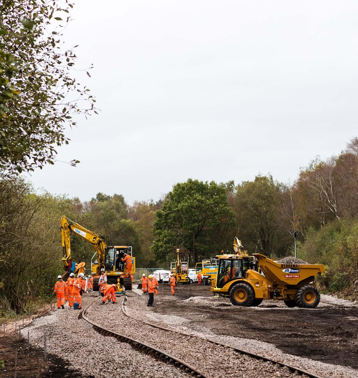
Practical Trackwork Challenge Churnet Valley Railway
The third Practical Trackwork Challenge (PTC) was held on the Churnet Valley Railway on 9 and 10 October. The practical trackwork challenge consisted of relaying 250 m of track near Leek Brook Station to complete stage 1 of the preservation railway’s project to “Reconnect Leek”. This first stretch of track was funded by Churnet Valley Railway and Staffordshire Moorlands District Council.
The PTC is essentially a training course that allows people who work in the industry but who have little or no site knowledge to experience working in a live railway environment in a safe and controlled manner. Participants are split into two groups and can undertake all of the tasks involved with track renewals under expert supervision, whilst a plain line track renewal is taking place. The challenge is non-competitive. This year the 40 participants included a site agent, possession planners, resource planners, a PhD qualified geotechnical engineer, a civils supervisor, track designers and a signalling engineer. The participants assembled at the Borough Arms Hotel in Newcastle under Lyme on Tuesday 8 October for a pre-course meal and a detailed briefing of the works to be completed over the next two days.
Any track renewal takes time to plan and to prepare for properly whether that renewal is on a 125 mph mainline or on a 25 mph preservation railway. So, prior to the PTC taking place, PWI representative and experienced railwayman Malcolm Pearce had been hard at work for many months procuring materials, machines and designs. A team from the joint Balfour Beatty Transport for London office based near London Victoria had surveyed and designed the new layout and had set out the works prior to the start of the challenge. Malcolm and another PWI “old hand”, Roy Hickman, had spent time with machine operatives and machines supplied by Quattro and TXM Rail plant clearing the site of debris and vegetation and installing messing facilities so that the challenge could go ahead. Of course, the setting out, site set up and all of the other prechallenge work could not have happened without the great support provided by the Churnet Valley Railway’s band of volunteers.
On day one the participants gathered on site at 09:00 for a detailed safety briefing. The first group were then shown the principle of two-dimensional (“2d”) installation using a balanced laser, ably demonstrated and explained by Balfour Beatty Engineer, Jonathon Wright.
 AUTHOR Andy Steele PWI Technical Content Manager
Andy has 35 years’ experience of surveying, design, renewal and maintenance of the Permanent Way. He has worked for British Rail, GTRM / Carillion, Owen Williams and Amey. Andy has worked mainly on the British mainline network but he has also had brief experience working on the Underground for Tubelines whilst with Amey and for NIR on secondment from British Rail.

22
This was an incredible opportunity to be hands-on and experience the physicality involved in renewing a railway.


23
DELEGATE FEEDBACK
Jonathon also demonstrated how the receivers to the balanced laser are set up on the blade of the dozer. Following this explanation, the dozer set to work trimming the formation to the correct gradient and installing a cross fall of 1 in 40 into the cess under the new track alignment.
Whilst the first group were being shown how to trim the formation and cut a cross fall, the second group were learning about small tools and powered plant under the direction of Jon Winborne of Cleshars. Jon is a qualified trainer and he enthusiastically demonstrated the small powered tools including the impact wrench, disc cutter, auger and rail drill as well as encouraging our challenge participants to handle them and start them up. Jon concentrated on how to handle all of the tools safely. He also demonstrated the numerous hand tools that everybody would use later in the challenge, such as the jacks, sleeper nips, bars, keying hammers and of course that most ubiquitous of all plate layers tools, the good old shovel. The information gained from this briefing would prove to be invaluable for our participants later in the challenge.
The site was now ready to drop the bottom ballast. Jonathon Wright and James Field of Balfour Beatty had shown the groups how to mark up the edge of the ballast from taking offsets to the setting out pegs and the edges of the track bed had been marked out in paint. The dumpers then placed the bottom ballast and the dozers graded it level and to a depth of 150 mm. All the participants were able to gain hands on experience of checking the ballast depth and setting up the balanced laser to the design gradient.
As described previously there were several machines on the site; 360 diggers loading ballast into dumpers and a dozer to grade both the ballast and formation. The safety briefing in the morning by Owen Stratford of Balfour Beatty had explained the principles of exclusion zones around machines and also explained the duties of the crane controller. However, a session was set up where a crane controller explained to the groups exactly what his role was, the general principles of what they were trying to do and the purpose of the crane plan. The participants were each given the opportunity to sit in the cab of a RRV 360, watch the operator rotate the machine and were made aware of the blind spots, the areas where the machine operator cannot see an operative on the ground.
After lunch our groups started to prepare the existing track ready to attach the new track panels. This session was led by track supervisor Steven Day-Murphy of Balfour Beatty who is attached to the Central Track Alliance. Steven set about organising our participants with gusto. Our groups trimmed the rail ends with the disc cutter and learned how to square across the cut at 90 degrees by taping out a 3,4,5 triangle. Two new sleepers with baseplates were installed at the end of this existing panel, which involved digging away some very old and very compacted ballast indeed. Steven’s vocal encouragement urging the group to bend their backs certainly helped the job to be completed in a timely manner, or something like that anyway!! Steven then demonstrated how to remove that stubborn ballast and achieved more in ten seconds than our group achieved in ten minutes. I think our groups learned just how much physical effort is needed during a renewal. Steven showed them what he had already told them.


24
The event felt realistic, rather than staged in a safe environment, and allowed me to see in real time the considered response to uncontrolled changes.

DELEGATE FEEDBACK 25
Under the supervision of Jon Wimborne, the groups used the impact wrench to change some broken baseplates on the existing panel. They learned how to jack the rail, replace keys to the bull head chairs and the purpose of the bolts and ferrules. It was great to see our groups gel into teams and all were enthusiastic in their participation.
The author of this piece has worked on the railway for over 35 years and has no experience of a bullhead renewal at all, so at the end of day one, I talked to the site engineers, Owen Stratford and Jonathon Wright as I was impressed with their knowledge of the bullhead componentry that we were installing. For example, the baseplates were all dated 1951 and both Jonathon and Owen knew about the seat depth and the jaw lipping on certain plates. I asked them if their knowledge was due to working on the London Underground where bullhead use is more prevalent than in the national rail network. Owen works on a preservation railway in Norfolk in his spare time and Jonathon too works on preservation railways in the South East keeping the skills alive.
Day two began with another good safety brief from Owen Stratford which like all the briefings was interactive. He asked some good questions of the group; where the safe walking route to site was, where the muster point was should we need to evacuate the site and also the importance of wearing gloves and the need to be aware of trapping fingers in the tasks that were to be completed that day.
Malcolm Pearce started the day by propelling an engineering train onto the site loaded with track panels, loose rails and other materials including


keys, baseplates and ferrules. Once on the site the groups were able to observe a tandem lift made by two of our machines to lift the panels off the train and place them onto the new bottom ballast. James Field positioned all of the panels from his offset pegs. The groups then had the opportunity to install the fishplates between the panels.
Jonathon Graham from the Rail Accident and Incident Branch (RAIB) delivered a very interesting, informative and interactive session on the work that the RAIB conduct and went through some of the reasons how and why trains de-rail from the track. Jonathon stated that the British railway network was one of the safest in the world and was the second safest in Europe after Luxembourg, and of course we have many more miles of track than the Grand Duchy. He expanded on the reasons why trains de-rail with his groups and explained that trains are far more likely to de-rail within switches and crossings (S&C) than in plain line. He went into some detail on the highest risk area of all, that is when a train passes over a switch in the facing direction.
Jonathon then discussed the process and demonstrated the gauges used in facing point inspections, known throughout Network Rail (NR) as “S053”. For a train to de-rail it is necessary for a train wheel to lift off the rail, but it is also necessary for that train wheel to shift across the rail. He stated that where track geometry transitions from straight to curved there is often a kick of high cant deficiency which will make a train naturally lurch to the outside of a curve. He then explained to the group the principle of twist with an analogy about a wobbly table in a restaurant.
DELEGATE FEEDBACK 26
The operations were explained in a civil manner without undue haste, which provided an ideal environment for understanding and to ask questions.
It was brilliant to be able to use tools and be in an environment where you had time to ask as many questions as possible, but it was also good to have a bit of pressure on the second day to appreciate the situation of needing to hand back after a possession.
It was invaluable to meet people with a huge range of experience and knowledge. Leading experts of the industry took a lot of time and effort to train us. It was great to know that they are willing to share their knowledge.

Thank you.
DEL EGATE FEEDBACK
I found the event to be very useful for my professional development and I met some great people!
The comradery and willingness to share knowledge was appreciated.
DELEGATE FEEDBACK 27
Twist is a difference in cant measured over 3 metres or a train bogie length and will cause a wheel to lift from the rail if the cant difference is large enough. These two factors, twist and high cant deficiency, combined with high friction will cause a derailment anywhere in plain line or S&C, but is more likely at facing points. He described the principle of flange climb at the switch tips and showed the group on site the difference between straight cut and undercut switches. Jonathon described chamfered switches which are the current standard for switches used in the mainline network. He explained that by lubricating the first metre of a facing point, rail friction can be substantially reduced. By utilising a gauge which mimics a wheel set, Jonathon accurately described to the group how flange climb can happen if the switch rail is offset just 4 mm foul of the stock rail. He demonstrated the red and green lines on a standard track gauge as a go/no go gauge for points of contact to the running faces of the rails.
Jonathon explained the purpose of stretcher bars and talked about the example of the accident at Grayrigg where lack of maintenance to the stretcher bars caused the train to leave the track and where sadly a female passenger was killed.
The session went on to discuss removing track workers from the presence of trains particularly when patrolling. Jonathon described the plain line pattern recognition system (PLPR) used on NR’s track recording trains, where photographs are taken at each sleeper recording differences from the expected shape caused by conditions such as missing rail fastenings.
These differences are noted and flagged to the track maintenance engineer who can rectify then in first available white period.
The dumpers then unloaded more ballast onto the new track. Steven Day Murphy then organised a machine fitted with a ballast plough to profile the ballast. The purpose of the plough is to create a ballast shoulder and to remove excess ballast from the sleepers. The plough is an attachment that fits onto the end of an arm on one of the RRV360 machines. This process was only partially successful as the plough is designed to fit onto flat bottomed rail and concrete sleepers not bullhead rail, chairs and wooden sleepers. It was absolutely great to see all of our participants pick up shovels and start removing the ballast from the chairs and sleepers in readiness for the tamper. Steven most certainly didn’t need to use any vocal encouragement at this point.
The engineering train had returned to the depot and the tamper was brought to the site. The tamper is owned by the Churnet Valley Railway and for the benefit of the tamper enthusiasts out there (of which there are many in the PWI) is an old 07 machine previously owned by Jarvis and Centrac (Tarmac).
The tamper finished its pass of the track just after 3 o’clock on Thursday afternoon and with that the challenge was complete. Our teams had completed a 250 m plain line renewal in two day shifts and learned lots of new skills.PWI CEO Stephen Barber closed the challenge by presenting certificates to all 23 participants. It should be noted that more than a quarter of the students were female and whilst as an industry
The most enjoyable aspect of the event was the opportunity to observe track laying by professional contractors at close quarters, using present-day methods and machinery.


DELEGATE FEEDBACK 28
The RAIB presentation on derailment was first class.
DELEGATE FEEDBACK
Jonathon Graham (Inspector of Railway accidents at RAIB) explained the purpose of stretcher bars and talked about the example of the accident at Grayrigg where lack of maintenance to the stretcher bars caused the train to leave the track and where sadly a female passenger was killed.


all 23 participants.
It should be noted that more than a quarter of the students were female and whilst as an industry we are far from parity between the sexes, it is refreshing to see a proper balance beginning to happen at long last.
PWI CEO Stephen Barber closed the challenge by presenting certificates to
29
we are far from parity between the sexes, it is refreshing to see a proper balance beginning to happen at long last.
The PWI Practical Trackwork Challenge is a carefully curated learning experience that would not be possible without the support of our industry friends.


We are very grateful to Churnet Valley Railway for hosting this year, and to the many companies who gave their time, resources and staff, including TXM Plant, Quattro Plant, Cleshar, TFL, Network Rail, AECOM, RAIB, VolkerRail, SNC Lavalin, Balfour Beatty, Swietelsky Babcock Rail, Story Contracting, ORR, Costain, Stobart Rail, Jacobs and Shannon Rail.


We would also like to extend a special thanks to Roy Hickman and PWI Honorary Life Member Malcolm Pearce whose commitment to delivering a comprehensive, safe and efficient challenge was immense.

Last but not least, thank you to all the young professionals who participated. We hope that you enjoyed the experience and we look forward to seeing you out and about on track again soon!
Finally, we are already planning our next Practical Trackwork Challenge which will take place in the Autumn of 2020. If you would like to enquire about being involved in next year’s challenge, either as a potential host or supporting company, please contact kate.hatwell@thepwi.org


We are very grateful to Churnet Valley Railway for hosting this year, and to the many companies who gave their time, resources and staff. Thank you.
ALL AT THE PWI
Setting up 2D laser - basic principles by James Field New track formation and haul road preparedTrack
alignment and longitudinal level pegs set by TfL survey & design team
Prepared ballast bed ready for track laying
30
OTP D41 laser guided dozer preparing ballast bed Prepared ballast bed ready for track laying


 Individual appreciation of OTP operational and safety regime by TXM OTP supervisor
Appreciation of SPP operation and use of hand tools by Cleshar supervisor / trainer
Manual sleeper threading by team members
Materials train on newly laid track
Cleshar operative using rail saw
Tightening fishbolts manually
Hydrema dumper unloading trackbed ballast
Team carrying chaired sleeper to position
Tightening fish bolts utilising an impact wrench, supervised by Cleshar trainer
Teams distributing and boxing in ballast manuallyMaterials train approaching site
OTP in tandem for lifting, carrying and placing 18.3 m track panels
OTP with fork attachment preparing to unload sleepers from wagon in groups of four
Individual appreciation of OTP operational and safety regime by TXM OTP supervisor
Appreciation of SPP operation and use of hand tools by Cleshar supervisor / trainer
Manual sleeper threading by team members
Materials train on newly laid track
Cleshar operative using rail saw
Tightening fishbolts manually
Hydrema dumper unloading trackbed ballast
Team carrying chaired sleeper to position
Tightening fish bolts utilising an impact wrench, supervised by Cleshar trainer
Teams distributing and boxing in ballast manuallyMaterials train approaching site
OTP in tandem for lifting, carrying and placing 18.3 m track panels
OTP with fork attachment preparing to unload sleepers from wagon in groups of four
31
Hydrema dumper unloading trackbed ballastTeam members manually packing run in sleepers prior to passage of materials train


 Teams manually fine aligning track
OTP in tandem for lifting, carrying and placing 18.3 m track panels
Materials train on site; wagon conveying chaired sleepers in groups of four
Tamping and lining newly laid track
OTM tamping and lining newly laid track
Tamper setting up for work
Hydrema dumper side tipping boxing in ballast
RRV with ballast profiling tool attached
Teams manually fine aligning track
OTP in tandem for lifting, carrying and placing 18.3 m track panels
Materials train on site; wagon conveying chaired sleepers in groups of four
Tamping and lining newly laid track
OTM tamping and lining newly laid track
Tamper setting up for work
Hydrema dumper side tipping boxing in ballast
RRV with ballast profiling tool attached
32
OTP in tandem placing 18.3 m track panel to design position

33
Huge thanks to photographers Chris Seddon (www.cseddonphoto.com) and Dave Gibson (www.blazerweb.co.uk/drgibson/)
HS2 Gauging – The Uniform Structure Gauge (USG)
INTRODUCTION
Gauging is an integral part of any railway system. This paper describes the HS2 approach to gauging and it shows how HS2 established 4 different Uniform Structure Gauges (USG) which suit their specific infrastructure. The paper also provides an overview on how USGs are calculated.
BACKGROUND
Every Railway Infrastructure manager has to ensure that the type of rolling stock on their system can be run in a safe manner from a spatial perspective, ie the trains don’t hit parts of the infrastructure or other trains. This is achieved by means of ‘Gauging’. For HS2 gauging the TSI is applicable which refers to Euro Norms (EN) to determine structure gauges for new and interoperable infrastructure.
In general, a structure gauge is an envelope describing an area that must not be infringed by any infrastructure or lineside equipment under any condition (see figure 8).
Even though EN calculation methods for structure gauges are predetermined, the Infrastructure manager has options to create different structure gauges that suit their specific needs. For example, they might want to have a ‘Uniform Structure Gauge’ (USG) which is applicable to specific areas such as tunnels, the open route, stations, station approaches, depots etc.
The following points will give the reader some general background on gauging.
WHAT IS GAUGING?
Gauging is the process for ensuring that trains which are used on a specific section of track and the railway infrastructure are compatible in terms of spatial relationship. These days gauging is a scientific method which creates an artificial train envelope that is greater than the physical train, taking into considerations items such as track geometry and speed amongst others.
Independent of the gauging method used (see further below), the resultant envelope determines the space that must not be infringed on by any part of the infrastructure or line side equipment. The resultant envelope might be called Structure Gauge (eg in the EN) or the Swept Envelope in other standards. The latter usually requires additional distances (clearances) to be kept to the envelope.
EXAMPLES OF TYPICAL AREAS WHERE GAUGING IS REQUIRED
Typically, gauging is required for the following scenarios:
CLEARANCES TO STRUCTURES AND EQUIPMENT
The most common structures and equipment to stay clear of comprise:
1. Overbridges (soffit and abutments)
2. Tunnels including evacuation walkways and associated equipment (e.g. ventilation fans, OLE, cable troughs etc.)
3. Lineside equipment such as signals, masts, posts, speed boards etc.
4. Platform offsets. Platforms are special structures, as trains have to pass them at a relatively close distance. This is because of a ‘conflict of interest’ between structural clearances and appropriate stepping distances. A sufficient clearance to the platform is essential and has to be guaranteed for stopping and potentially for fast, non-stopping trains. However, for passenger friendly stepping distances, trains need to be as close to the platform as possible.
TRACK SPACING AND PASSING CLEARANCES
Track spacing is the distance between railway tracks. For NR, a standard spacing is 1970 mm between the running edges of the rails on straight track which equates to 3.405 m between track centre lines (CL). For HS2, the track spacing, measured from CL to CL, is dependent on speed. This is because with increasing speeds, aerodynamic considerations must be taken into consideration. HS2 uses track spacings which are compliant with the TSI and which are similar to other European high-speed administrations. Therefore, no analysis needs to be undertaken to prove these track spacings are sufficient. As the TSI only covers speeds of up to 350 km/h, a track spacing of 4.7 m has been specified by HS2 for speeds between 350 km/h and 400 km/h. This is 0.2 m wider than the track spacing required by the TSI for speeds > 350 km/h. HS2 appreciate the fact that future improvements in aerodynamics might have to be achieved so the speed could be raised to 400 km/h should this be implemented at some stage in the future.
AUTHOR Klaus Pajung Senior Permanent Way Design Engineer
Klaus is a Senior Permanent Way Design Engineer with an overall experience of 17 years. He is a Chartered Engineer in Germany (Diplom Ingenieur - FH).
Klaus came to the UK in 2005 and stayed with Atkins in Birmingham for the following 3 years. There he mainly worked on S&C schemes at various design stages.

Klaus then moved on to Halcrow in London who he is still with, (now Jacobs). There he worked on NR schemes at various GRIP stages, TfL projects and international projects.
He is currently seconded to HS2 where he is looking after the track alignment including the associated standard, the S&C geometry standard and the gauging standard.
34
Figure 1: Fouling point as per Spanish gauging standard for through speeds >120 km/h.
FOULING POINTS
Fouling points (FP) are points between the through track and the diverging tracks of a turnout or crossover arrangement beyond which trains would collide if both tracks were occupied at the same time. To establish the appropriate position of fouling points the relevant structure gauge (Limit Gauge for EN gauging) must be calculated. See Figure 1 as an example.

GAUGING METHODS
There are different gauging methods which are described as follows:
ABSOLUTE GAUGING
Absolute gauging is mainly used on existing infrastructure. It is a full assessment of clearances on a section of existing track between the vehicle and fixed infrastructure and the vehicle and vehicles on adjacent tracks. These days absolute gauging is executed by means of computer programmes like ClearRouteTM, DGauge etc. These programmes consider the whole suite of rolling stock used on a section of track with all their characteristics (static envelope, suspension, bogie distance etc.). They also consider track related properties (track form, curvature, cant, speed etc.) and wear, likely track movements etc. to calculate a swept envelope. This swept envelope is an enlarged version of the static envelope and used by the software to determine clearances to the existing infrastructure. Most railway administrations will define a clearance to the swept envelope that has to be met. For example, NR define a clearance of 100 mm to the Swept Envelope as ‘normal’ in many cases. Figure 2 is a typical ClearRouteTM output showing structural and passing clearances for a wide range of rolling stock.
COMPARATIVE GAUGING
Comparative gauging is the process of comparing the swept envelope of a new vehicle with the swept envelope of a vehicle or vehicles which have demonstrated to comply with gauging requirements of a track section. This way conclusions can be drawn on whether this new vehicle can be used on a specific route section or not.
DEFINED GAUGE METHOD AS PER EURO NORM EN 15273
The defined gauge method described in EN 15273 (Parts 1 and 3) is split into 3 main methods:
A) The static method is used for specific, noninteroperable networks.
B) The dynamic method is used on certain networks with the aim of optimising the space available for sizing non-interoperable vehicles.

HS2 GAUGING
HS2 have 4 USGs as described below. This is to avoid having a single and very large USG which would use worst-case input values from across the system.
On the one hand such a single structure gauge would be user-friendly for the Infrastructure manager. On the other hand, an oversized single structure gauge would mean that structures or lineside equipment would have to be further away from the tracks, therefore potentially increasing footprint and cost. This is in particularly true for tunnels as with a single route-wide USG the diameters of many tunnels would have to be increased.
This section provides some background information and detail on various aspects of HS2 gauging.
USE OF THE SPANISH GAUGING STANDARD
HS2 gauging is based on the Spanish gauging standard (FOM/1630/2015) which is well established and has a proven record for high speed railways. It is based on EN15273 and in fact, is a further development of the EN which ‘puts meat on the bone’ in sections where the EN is rather vague. For example, EN152733 (section 5.5.3) provides two examples of scenarios for the calculation of USGs which might be considered:
• The worst-case situation: Worst-case input values are considered such as smallest radius, the maximum cant or cant deficiency etc,
• Defining of the gauge with two profiles: One profile applicable on a straight or curved track with very large radii and no cant. Another profile on a curved track designed on the basis of the worst-case cant and radius situation.

The Spanish gauging standard describes the second scenario in detail; considering 8 different scenarios as a result (see calculation section for more detail).
The HS2 calculation methodology is based on this second scenario.
TYPES OF GAUGES REQUIRED FOR HS2 GAUGING
HS2 use the following types of gauges in their standard:

Figure 4: Principle of EN structure gauge determination

C) The kinematic method is used in Europe mainly on interoperable networks. It is therefore used by HS2 and discussed further in this paper.
• Uniform Structure Gauge (USG). The USG is used to determine the distances to be kept to between structures and equipment and to the trains and therefore to the tracks. HS2 developed 4 different USGs for different areas of application along the route These are summarised in table 1. More explanation on how HS2 arrived at these is discussed later in this article.
Figure 2: Typical ClearRouteTM output for structure and passing clearances
Table 1: HS2 Uniform Structure Gauges
Figure 3: Overlay of area-wide USG (black) and local USG (red)
35
• Structure Installation Limit Gauge. This gauge is used for platform offsets, track intervals and fouling point considerations. It is not discussed in this article.
• Pantograph Gauge. This gauge determines the space required for the pantograph structural and electrical clearances. It is not discussed in this article.
In their gauging standard, HS2 allows local USGs to be developed in specific locations where none of the four HS2 USGs can be applied. For example, both USGs for tunnels (USG 1 and 2) allow for a limiting maximum cant of 160 mm. Should a designer propose an exceptional cant of say 180 mm in tunnel, then they will have to calculate a local USG using all worst-case input values relevant for the section where the 180 mm of cant are applied. They must then compare the resultant local USG with the area-wide USG (in this case USG 1 or USG 2). If the local USG is outside or partially outside the area-wide USG (see example in figure 3), then the local USG must be used. Otherwise the area-wide USG must be applied.
THE KINEMATIC GAUGING METHOD
The kinematic gauging method is used to create structure gauges called Structure Installation Nominal Gauges (SING) amongst other gauges which are not discussed in this article.
The Uniform Structure Gauge (USG) is a specific case of a SING. It is calculated in the same way but using worst case calculation input values occurring in a specific area of application, e.g. all open route sections.
The term USG will be used in this article for simplicity unless a clear distinction needs to be made between SING and USG.
USGs are structure gauges describing a theoretical maximum train envelope which must not be infringed on by any structure or equipment. They are developed from a reference profile (see Figure 5). The size of the reference profile is increased horizontally and vertically to be a USG. This is achieved by adding associated rules which take into consideration various factors such as speed, geometry, track form etc. that are not part of the reference profile. The principle of this process is summarised in Figure 4.

For the kinematic gauging method, EN 15273 mandates the use of kinematic reference gauge GC for the upper part (h>400 mm) and GI2 for the lower part (≤400 mm). These reference gauges represent the outermost boundary to which a train manufacturer can design taking into consideration maximum load and suspension dissymmetry. The actual as-built train envelope must fit within the static reference GC gauge.
The GC gauge is applicable to all HS2 rolling stock which will comprise of two types of passenger trains; (‘Captive’ trains for use on the HS2 network only and ‘Classic Compatible’ trains which are also used on the NR network). Furthermore, this will be applicable to any maintenance trains on the system. As Classic Compatible trains are smaller they do not use GC Gauge, therefore they don’t have to be gauged separately on the HS2 system (but they do on NR infrastructure).
The kinematic gauging method is simpler than the absolute gauging method described above. Its key advantages are:
• User friendliness. No specialist software is required to calculate clearances once USGs have been determined. The USG, for example in form of a CAD file, can be copied or referenced into a cross section. This way infringements can be detected easily.
• Low number of USGs required for the whole system. USGs can be applied for large areas of the railway infrastructure and don’t have to be calculated for various individual geometrical constraints, rolling stock etc.
As a disadvantage, USGs are usually more conservative than swept envelopes calculated using the absolute gauging method. However, on a newly designed railway this isn’t normally a major concern.
CALCULATION OF THE UNIFORM STRUCTURE GAUGE
In general, calculations are carried out for all 8 points of the reference gauge (see figure 5) for both horizontal and vertical directions. However, there are many exceptions to this rule, in particular, for points below the rotation centre height (taken as 0.5 m). Furthermore, many vertical calculations are undertaken for Point 1 only.
Calculations vary depending on whether points are on the inside or the outside of a curve. Furthermore, different speed scenarios are taken into consideration with v = 0 km/h and v = vmax. A more detailed description on scenarios taken into consideration is provided later in the article.
Once calculations are completed, a symmetrical USG is created using the worst X and Y values of all scenarios. X and Y values, e.g. for the Reference Profile, are the ‘coordinates’ shown in Figure 5. For example, the coordinates of Point 1 are 1.540/4.700. The following calculation methodology has been simplified to not exceed the scope of this article.
A) REFERENCE GAUGE
The kinematic method, BS EN15273-3 mandates the use of kinematic Reference Gauge GC for the upper part (h>400 mm) and GI2 for the lower part (h≤400 mm) the boundary between which is represented by point number 4 in Figure 5.
B) INPUT VALUES
Input values are described in EN15273-1 and EN15273-3 and selected by the Infrastructure manager as appropriate. HS2 made the conscious decision to only allow input values which were at least in the limiting range as per the HS2 Track Alignment standard regarding cant and cant deficiency. Therefore, if designers use exceptional design values they are no longer ‘covered’ by the HS2 USGs and must calculate an area specific USG as described above.
Input values are as follows:
1. Track form (ballasted track or slab track)

2. Track quality (very good or ‘other’). For HS2 the assumption is that after installation the track quality is very good and that it is maintained to this standard. Quality is based on track quality measuring coach outputs. For depots ‘Track quality other’ has been assumed as depots are usually not as well maintained as main lines.
3. Track geometry
l nom : Nominal track gauge (1.435m)
RH : Minimum horizontal curve radius
RV: Minimum vertical curve radius (hog or sag)
D max /I max : Maximum cant and cant deficiency
Other factors which are less commonly known
4. Speed
5:
36
Table 2: Overview of scenarios taken into considerations for a USG.
Figure
Kinematic reference gauge
Figure 6a: Typical PT point (here to inside of curve).
C) ASSOCIATED RULES AND FORMULAE
Associated rules take into consideration various phenomena that are not part of the reference profile, therefore increasing its size. This way they will enlarge the reference profile horizontally and vertically to be a USG.
D) LATERAL CALCULATION OF USG POINTS
In general, the lateral points of the USG are determined by calculating Associated Rules which increase the width of the reference profile. Calculations are done for all points of the reference profile unless stated otherwise.
In general, the width of the USG is calculated using the following equation and terms. However, different scenarios have to be considered, some of which will change this generic formula (as described in point G. below).

The last four terms denote the Associate Rules.
bnom i,a ≥ b cr + si/a + qsi/a + ∑2b + M3b
horizontal associated rules
where: i/a factors which are to the inside to inside (i) or outside (a) of a curve
bnom i,a lateral coordinate of USG point b cr semi-width of the kinematic GC reference profile

si/a additional overthrows
qsi/a quasi static roll, calculated above height of rotation centre (0.5 m)
∑2b horizontal displacements (also referred to as Σj,j*) due to horizontal track position, horizontal c ant deviation, vehicle dissymmetry and oscillation (Δbx in point F below). In the EN, this is also referred to as allowance M1 + M2 which define ∑2
Figure 6b: HS2 “PT line”.

M3b additional value which is to be determined the infrastructure manager. It covers specific aspects regarding the use of vehicles or loads larger than those allowed by the gauge, aerodynamic and other considerations (0mm for HS2)
E) VERTICAL CALCULATION OF USG POINTS

In general, the vertical points of the USG are determined by calculating Associated Rules which increase the height of the reference profile. Calculations are done for all points of the reference profile unless stated otherwise. The height of the USG is calculated using the following equation and terms.
However, as described in point G. below, different scenarios have to be considered for the calculation, for some of which the signs of individual summands will change.
The last four terms denote the Associated Rules.
h nom ≥ h cr + ΔhRv + ΔhPT + Σ2h + M3h
vertical associated rules
where:
h nom vertical coordinate (height) of USG point
hCR reference profile height
ΔhRv vertical raising or lowering on a vertical curve. This is relevant for the upper part only. For points at the same level or above the maximum width (i.e. Points 1 and 2), resultant values are added, for points below this level (i.e. Points 3 and 4) values are deducted.
ΔhPT super elevation of the upper parts due to the vertical effect of the roll (only relevant for Point 1). This term depends on the angle α PTi,a which is rotation of the gauge due to the quasi-static effect. This term can differ between the inside of the curve and the outside of the curve. For the inside, it takes into c onsideration cant whereas for
the outside it takes into c onsideration cant deficiency.
∑2h vertical displacements, also referred to as ∑ V,V* , due to vertical track position, vertical cant deviation, vehicle dissymmetry and oscillation (Δhx in point F. below). The sum of the allowances is determined for point PT only (Point 1).
M3h similar to the horizontal calculations this term refers to an additional value which is to be determined by the infrastructure manager (0 mm for HS2).
F) ADDING-UP RESULTANT HORIZONTAL AND VERTICAL Σ2 ALLOWANCES
For the SING, Σ2 allowances are added up arithmetically according to the formulae below. This is as per the Spanish gauging standard which is advanced in its interpretation of the European gauging norms and which is also used for high speed.
1. Horizontal Σ2:
2. Vertical Σ2:
The resultant sums feed into the eight different USG scenarios to be considered which are described below.
G) CONSIDERATION OF DIFFERENT SCENARIOS FOR THE FINAL UNIFORM STRUCTURE GAUGE
To arrive at a final USG, eight different scenarios have to be considered. For each of these scenarios specific associated rules are calculated. The Spanish gauging standard states in section 3.3 that the following cases have to be considered for both vehicles at maximum speed and static vehicles:
1. Maximum lateral displacement with its compatible displacement perpendicular to the running surface. This scenario is relevant for curved track.
37
2. Maximum displacement perpendicular to the running surface with its compatible lateral displacement. This scenario is relevant for straight track and large radii.
Furthermore, as per section 5.2.1.3 of EN15273-3, the quasi static effect must be considered taking into consideration speeds:
A) “outside the curve, under the cant deficiency effect”. This is relevant for the maximum speed.
B) “inside the curve, under the cant effect”. This is relevant for a stationary train (0km/h).
However, to cover all possible cases, scenarios A) and B) are calculated for both speed options, which is also in line with the Spanish gauging standard (section 3.3). This way 8 scenarios are created:
A) Case 1 above to the inside and the outside of a curve, both at a speed of 0 km/h and at the maximum speed (4 scenarios)
B) Case 2 above to the inside and the outside of a curve, both at a speed of 0 km/h and at the maximum speed (4 scenarios)
Table 2 provides an overview of the 8 scenarios for which these formulae are to be used.
H) THE PT POINT
The PT point is an additional theoretical point in the top corner of a USG. Its aim is to smoothen the USG that is created from the 8 scenarios described above. Where the reference profile is concerned, Point 1 is frequently referred to as the PT point as well.
In theory, establishing the outermost contour by connecting all No. 1 Points of the 4 USG scenarios (to both the inside and to the outside) would suffice to create a USG. However, this would create a rather complicated shape and could therefore not be user friendly for the enduser who is the Infrastructure manager.
In general, the PT point is determined once the 8 USG scenarios described above have been calculated. It is established separately for the inside (scenarios 1-4) and the outside (scenarios 5-8). The PT point is typically determined by intersecting the outermost vertical line of all scenarios beyond Point 1 and the top horizontal line beyond Point 1, see figure 6a. However, there is no rule stating that it must be done this way. Whereas this methodology provides a smooth USG envelope it also increases its size.
To minimise the size of the USGs, whilst having a smooth envelope at the same time, HS2 decided to eliminate the top corner created by the typical PT method described above. This could be achieved by connecting all four No. 1 Points with a “PT line” such that none of the points are outside this line (see Figure 6b). The ’savings’ made in the top corners are particularly relevant for areas where space is limited, such as tunnels. For example, for USG 2 the area of the top corners is reduced by approximately 100 cm2 on each side.

I) SYMMETRICAL USG
As stated further above, calculations vary depending on whether points are on the inside or the outside of a curve. To have a more userfriendly USG, it is made symmetrical at the end of the calculation process however, this is not
mandatory. This is done by selecting the worstcase X and Y values for each of the 8 points on either side and applying them to both sides.
HOW TO APPLY THE UNIFORM STRUCTURE GAUGE
USGs are applied perpendicularly to the plane of the rails as shown in figure 7. The calculations to determine the USG are such that the cant is not taken into consideration twice with this method.

DEVELOPMENT OF THE HS2 UNIFORM STRUCTURE GAUGES
Every Infrastructure Manager will eventually have to develop a USG or USGs which suit their infrastructure needs. This section describes how HS2 determined their USGs by applying the steps described below.
A) DETERMINE AREAS WHICH COULD HAVE THEIR OWN USG.
After internal discussions within the HS2 track team, initial areas as described below were selected. Each area is clearly defined and comes with its individual properties and constraints.
1. Terminus Stations. Characteristic input values for these USGs were low speed, no cant and no vertical curvature. It was anticipated that this could lead to a relatively small USG which would be beneficial for equipment close to the track in station environments.
Figure 7: Application of the USG (canted track).
Figure 8: Resultant USG 3 (prior to calculation of PT line)
38
2. Through platforms. At stations such as Birmingham Interchange, trains can pass a platform at speeds of up to 230 km/h. Typical input values for the USG calculation were high speeds on wide radii, no cant and no vertical curvature.

3. Station approaches. Characteristic input values for these USGs were relatively low speed on tight curves with cant and vertical curvature.
4. Open route. Input values for the USG calculation were based on worst-case open route track geometry values with high speed, tight radii (horizontal and vertical) and high cants and cant deficiencies.
5. Different types of tunnels. Input values for the USG calculation were based on worst-case track geometry for all HS2 tunnel types. These comprised bored tunnels with different diameters and cut & cover tunnels which can be on both slab track or ballasted track.
6. Depots. As one might expect, input values for this USG were low speed and tight curves without cant. All HS2 depots are on ballasted track.
B) ANALYSE THE TRACK GEOMETRY IN THESE AREAS TO DETERMINE INPUT VALUES FOR USG CALCULATIONS
The input values required are speed, horizontal and vertical radii, cant, cant deficiency and the track form (ballasted or slab track).
At this stage it became clear that some of the areas investigated could be merged due to the similarity of their calculation input values. For example, cut and cover tunnels were similar to 8.8 m and 9.1 m diameter tunnels.
C) CALCULATE INITIAL USGS FOR EACH AREA
Using the input values above, HS2 calculated 8 initial USGs using an Excel based tool. The USG calculation tool was developed in cooperation with one of the Engineering Delivery Partners who are experts in the field. By entering the input values, the spreadsheet calculates the associated rules for all 8 scenarios discussed in the calculation section (see table 2) and the resultant final USG. Furthermore, it will also calculate the structure installation limit gauge which is used for track intervals, the fouling point and platform offsets.
D) ANALYSE RESULTS AND RATIONALISE AMOUNT OF USGS
Once the results were available, the resultant 8 USGs were compared and grouped into similar categories. As a result, they were merged into 4 USGs as shown in table 1. Table 3 shows the results for the station approaches and the slab track tunnels to show their similarity. They were eventually merged into USG 3 (see figure 8). This was done by using the worstcase X values of the inside (i) and outside (a) and Y values of the inside and outside. X-values correspond to bnom and Y-values to h nom discussed in the calculation section above.
The most relevant points for this exercise are Points 1i,a (highest) and 2i,a (widest), they are highlighted in table 3.
To finalise the USG, a PT point (or PT line) still has to be calculated before making it symmetrical and therefore complete.
SUMMARY
The HS2 Uniform Structure Gauges were determined using EN15273 parts 1 to 3 as specified by the TSI. The Spanish Gauging Standard was used as a well-established interpretation of the Euro Norms.
The EN mandates that the kinematic gauging method is to be used for new and interoperable infrastructure.
HS2 determined specific areas within the system and investigated their gauging specific properties. As a result, 8 areas emerged for which initial USGs were calculated. These USGs were then analysed and rationalised. As a result, they could be reduced to the final 4 HS2 USGs.
REFERENCES
EN15273-1
European Norm BS EN 15273-2-2013+A12016, Part 1
EN15273-2
European Norm BS EN 15273-2-2013+A12016, Part 2
EN15273-3
European Norm BS EN 15273-3-2013+A12016, Part 3
Instruccion Ferroviaria de Galibos (FOM/1630/2015) Spanish Gauging Standard
TSI 1299/2014 Commission Regulation (EU) No.1299/2014 of 18 November 2014 on the technical specifications for interoperability relating to the ‘infrastructure’ subsystem of the rail system in the European Union.
ABBREVIATIONS
EN European Norm
FP Fouling Point
HS2 High Speed 2 NR Network Rail
SING Structure Installation Nominal Gauge
TSI Technical Specifications for Interoperability (infrastructure) USG Uniform Structure Gauge
Table 3: X and Y values for station approaches and slab track tunnels 39
Sheffield tram train pilot One year on – lessons learned
INTRODUCTION AND BACKGROUND
In 2006, the DfT and Network Rail set up an initiative to explore innovative vehicle options for urban and rural services as part of the replacement programme for the current fleet. During this exercise, the Tram Train concept was revisited following earlier attempts to apply it by BR Research in the 1990s.
A Tram Train vehicle is best defined as a tramcar capable of running both on street tramway and heavy rail networks. It is differentiated from other tramway vehicles through being equipped with technology to interface with heavy rail systems, particularly those related to signalling, control and telecommunications. An on-street tramway is defined as a steel rail guided transport system that operates in a street or reserved environment under highway traffic regulations and with line of sight operation (ORR, 2006).
A trial programme funded by the Department for Transport commenced in 2007 with the following objectives. (Objectives 5-7 were added in 2009):
1. Understand the changes to industry costs of operating a lighter weight vehicle, with track brakes, on the national rail network;
2. Determine changes to technical standards required to allow inter-running of light weight tram-type vehicles with heavy rail passenger and freight traffic and to gain the maximum cost benefit from Tram Train operation
3. Gauge passenger perception and acceptance of a light rail Tram Train service;
4. Determine the practical and operational issues of extending Tram Trains from the national rail network to a tramway system;
5. Devise a business case to support the longterm operation of Tram Train services in Sheffield/Rotherham and the wider UK;
6. Deliver the project within an agreed budget;
7. Gain direct experience of the processes that would allow Tram Train technology to be utilised elsewhere in Great Britain
The trial has been a collaboration between Network Rail, South Yorkshire Passenger Transport Executive (SYPTE), South Yorkshire Supertram Ltd (SYSL) and the Department for Transport with additional engagement from Northern Rail in the early stages.

Following extensive research in Germany where the concept was originally developed, the project team concluded that Tram Train works best when it links a street tramway with appropriate sections of the national network. This led to the pilot scheme between Sheffield Cathedral on the SYSL network and Parkgate on the national network which commenced in 2009 based on the Karlsruhe model.
THE KARLSRUHE MODEL
Karlsruhe is a city in South West Germany (Baden Wurttemberg), with a population of 1.3 million. It has an extensive tramway (70km) within the city that is operated by Verkehrsbetriebe
AUTHOR Ian Ambrose Senior Engineer Light Rail Network Rail

Ian entered the railway industry in 1985 as an IT specialist involved in the design of vehicle, infrastructure, operations and commercial systems.
Ian joined AEA Technology Rail in 2000 to develop emerging light rail and tram-train schemes. In 2006 he was invited to join Network Rail where he has seen the tramtrain pilot through from its inception in 2007 to delivery in 2018.
40
Tram and train pass at Rotherham Central (image: Ian Ambrose)
Karlsruhe GmbH (VBK). In the late 1950s the private narrow gauge Albtalbahn was taken over by Albtal-Verkehrs-Gesellschaft mbH (AVG), rebuilt to standard gauge and connected to the Karlsruhe tram network in 1961. Although the Albtalbahn has through running on to the tramway and uses both line of sight and heavy rail signalling, it is not true Tram Train as it is dedicated to tram vehicles with no freight or heavy rail passenger traffic
The first true Tram Train service was opened in 1992 between Karlsruhe and Bretten using an underused heavy rail line (see figure 1).

Prior to conversion there were 6 stations on the 19km route. After conversion there were 20 not including those on the original tramway. The number of passengers increased from 2000/ day before conversion to 8000/day immediately after conversion and to 14000/day by 1997. So successful has the concept been that extra lines have had to be built alongside the original route to accommodate the extra traffic towards Bretten. Tram Train has also been extended to other locations. The current Tram Train network is 561 km of which 287 km is on tracks owned or leased by AVG but on which freight can run and 274 km on track owned and controlled by DB. (Source AVG 2016).
The extension of Tram Train to Heilbronn 68 km away has led to the construction of a tram network there.


Tram Train has now been implemented in the German cities of Kassel, Saarbrucken, Braunschweig and Chemnitz with further projects planned in Bremen and Rostock.
Germany has federal regulations (LNT Richtlinie), that control the operation of light rail vehicles on heavy rail infrastructure. The relevant ones are:
• Tram Trains must not operate at speeds higher than 100 kph (62 mph);
• Tram Trains must not operate on lines where other trains operate at speeds higher than 160 km/h (99 mph);
• Brake performance must be according to tramway (BOStrab) requirements;
Figure 1: The Bretten line before and after Tram Train introduction
The Sheffield Tram Train Pilot Scheme
41
Figure 2: Route of the Sheffield Tram Train pilot service
• Tram Trains must feature all on-board equipment required for safe train operations (ATP with speed control, wireless communications, automatic vigilance device);
• Lines must be equipped with block operation and ATP;
• Operation only on lines with ATP where all heavy rail vehicles are equipped with ATP (both standard in Germany).
It should be noted that exceptions to all regulations are possible if the operation remains safe.
To summarise, the essentials of the model are to provide high frequency services, connecting the rural suburbs to the city centre, by connecting the railway to the tramway and avoiding the need to change from train to tram or bus.

THE TRAM TRAIN PILOT SCHEME
The service operates from Sheffield Cathedral stop on the Supertram network in Sheffield City centre to a new stop, Parkgate, at a shopping centre, about 1 mile north of Rotherham located on the former Great Central line from Woodburn Junction to Mexborough (Engineer’s Line Reference (ELR) WME). (See Figure 2). The tramway and national network are linked by a new chord at Meadowhall South Junction on the Supertram network to Tinsley North Junction on WME. The transition from tramway operation to railway operation takes place on the chord. Rotherham Central station was provided with tramway height platform extensions and the terminus at Parkgate is on a turnback spur operated under line of sight rules, with a refuge for an additional tram if required.
The service is operated by SYSL as part of the Supertram network. SYSL operate the service as an open access operator.

The service operates three times an hour, a clockface 20 minute service being unattainable due to fitting the service between the existing Northern services. The service operates for 17½ hours each day except Sundays, when a reduced hours service is in place. Journey time is 27 minutes enabling the service to be run with three vehicles and an operational spare. The route is electrified to 750V DC in line with the tramway. Passenger service commenced on 25th October 2018 and the service has carried over 1m passengers since then.
INNOVATION IN DESIGN/ CONSTRUCTION
To enable tramcars, which are essentially a road vehicle subject to highway legislation and running under unregulated line of sight operation, to venture onto the regulated, signalled national network, a number of innovations were required:
Network Rail Infrastructure:
• Overhead electrification at 750V DC using the Series 2 design to enable
 Figure 5: Trespass protection fence at Rotherham Central (Image: Ian Ambrose)
Figure 4: Train platform interface
Figure 5: Trespass protection fence at Rotherham Central (Image: Ian Ambrose)
Figure 4: Train platform interface
42
Figure 3: Innovation on Network Rail (Image: Network Rail)
compatibility with 25KV AC in the future. This was supported by one substation located at Ickles, which is approximately in the middle of the Network Rail
Overhead Line Electrification (OLE) section. The changeover between the SYSL and Network Rail OLE is located on the Tinsley Chord
• A signalling interface between the two networks with communication between the Network Rail and SYSL control centres to detect and accept Tram Trains plus TPWS at all signals on the route to prevent SPAD related collisions. Additional wrong routing protection is provided using the SYSL Vehicle Identification System (VIS) loops at the signals protecting Tinsley North and Parkgate Junctions. This only allows the route to be set on to the tramway if the loop is triggered by a Tram Train vehicle.
• Raised check rails provided at all turnouts to enable the Tram Train wheel profile to steer through Network Rail switches and crossings (see figure 3). Swing nose crossings can also be used to overcome this problem but were not used in Sheffield to reduce cost.

• Low level platforms were required at Rotherham central and Parkgate.

The low-level platforms are Rail Vehicle Accessibility Regulations (RVAR) compliant for the Tram Train vehicles (see figure 4) highlighting two potential risks:
• E xposed lower sector gauge on heavy rail vehicle increasing risks to passengers waiting on the low-level platform from turbulence etc. This has not been found to be any worse than the same risks at the standard platform height;
• The potential to encourage trespass on the railway which has been mitigated by a fence in the six foot (see figure 5).

TRAM TRAIN VEHICLES
SYPTE purchased seven Stadler (formerly Vossloh), Citylink vehicles very similar to those provided to AVG in Karlsruhe (see figure 6). The vehicles, Class 399, in the Rolling Stock Library (RSL) are three section articulated street tramcars with end loading enhanced to category 3 in EN15227, which is the current standard for Tram Train vehicles. The vehicles are also equipped with all the relevant heavy rail signalling, train detection and train protection equipment currently standard on all heavy rail vehicles as well as those used on the SYSL network. This includes the provision of both GSMR and the SYSL radio systems. The vehicles are also fitted for dual voltage working, although the 25KV AC equipment is currently isolated.
At 37.2 m, the vehicles are slightly longer than the original SYSL fleet necessitating some modification to the depot, but not to the tramway or tram stops.
The vehicles are UK highway legislation compliant to operate on the tramway, which required several deviations from Railway Group Standards to be approved. The most
Figure 8: Baseline tramway railway interface
Figure 7: Wheel rail interface
43
Figure 6: Citylink Class 399 (Image: Ian Ambrose)
significant of these were sanders, audible warning systems, lighting and magnetic track brakes, which were all successfully approved.

WHEEL RAIL INTERFACE
Embedded grooved track used for street tramways is not compatible with standard heavy rail wheel profiles and the thinner, shallower flange used on trams creates a high derailment risk when passing through heavy rail switches and crossings. This required both a unique wheel profile for the vehicles and modification to the main line infrastructure, which was developed in conjunction with the Institute of Rail Research (IRR) (see figure 7).
OPERATION AND INTERFACE MANAGEMENT

The Tram Train operation not only involves transition from one railway undertaking to another (SYSL and Network Rail) but also a transition from tramway to railway rules. Ideally this should be kept as simple as possible with the aim for a single boundary point covering ownership, operating rules, signalling and maintenance (see figure 8).
However this is not always possible in reality due to design constraints. In the case of the interface at Tinsley, the design of the chord has resulted in a very complex set of boundaries and associated interface management (see figure 9).
MAINTENANCE BOUNDARIES –WHY SO MANY?
One of the most complex parts of the Tram Train project has been the designation of formal boundary interfaces between the two systems. To avoid confusion or misallocation, each specific maintenance boundary required a clearly defined limit at or overlapping with each operator’s infrastructure. Critical maintenance boundaries included Track, Signalling, OLE and Civils, resulting in up to 12 formalised boundaries requiring proactive management in normal service. Each boundary
 Figure 11: Tram Train approvals process
Figure 9: Tinsley tramway railway boundaries
Figure 11: Tram Train approvals process
Figure 9: Tinsley tramway railway boundaries
44
Figure 10: Extract from RAIB report on Wimbledon derailment in November 2017
Figures 12: Commissioning tests
has the potential to impact another by virtue of the location assigned and the physical profile of the infrastructure at the boundary itself. The designated land boundary forms the starting point for this, with physical infrastructure boundaries following suit. An example of this is the track maintenance boundary, which was defined in its current location due to track curvature restrictions at the land boundary and rail design on the Supertram system.
This in turn affected how the alignment was formally defined, resulting in the tramway/ railway boundary falling almost 100 metres away from the land boundary. On the other hand, some boundaries are defined by the physical nature of the design, such as OLE and signalling. Both examples have resulted in a ‘maintenance overlap’ at each respective location. Maintenance overlaps require clear definition and suitable training to ensure incidents, such as the Wimbledon derailment in November 2017, are avoided (see figure 10).
As a result, customised training packs were developed for each critical boundary discipline and briefed to maintenance stakeholders prior to system commissioning.
INTERFACE METHOD OF OPERATION
Designation of maintenance boundaries has a significant effect on the method of operation over the system interface. Historically, private owner rail interfaces have always been signalled (or compliant with signalling regulations) making operation simpler.
A tramway connection introduces an unsignalled interface requiring a new method of operation to cover the transition. As a result, ‘Line of Sight’ operation was developed and a new set of local regulations drafted to ensure basic signalling regulations could be accommodated as far as possible for Tram Trains traversing the interface. Due to restrictions imposed by the connection design, specifically the location of a centrally located access road crossing, the length of ‘Line of Sight’ operation was extended significantly, placing the operational rules boundary within Network Rail infrastructure. This required development of contingencies for degraded working, given the non-standard boundary definitions and track layout.
Most critically, the lack of ‘formally signalled’ infrastructure on the connection resulted in a shortfall of Network Rail staff protection methodologies. To compensate for this, a new method of protection ‘Possession of Line of Sight Infrastructure’ was introduced, to ensure staff from each organisation could access their respective boundaries to undertake maintenance.
This required extensive consultation to ensure compliance with both organisations’ track access standards and methods of protection. As per the training developed to cover maintenance boundaries, individual staff disciplines were formally briefed on the new protection methodology and what configuration was most applicable to the nature of work they would be undertaking on individual assets.
COMMISSIONING (see figures 12)
As both the Citylink vehicle and the new heavy rail infrastructure were granted exemption from the Interoperability Directive, the approvals and commissioning were undertaken under ROGS and CSM-RA, see RSSB publication “T1049, Operating non-mainline vehicles on mainline infrastructure - Guidance on the regulatory requirements” published in 2015 (see figure 11).
A commissioning plan was drawn up for the infrastructure and the vehicles incorporating a thorough range of tests to prove the systems. This included the safe operation of the OLE systems including emergency and SCADA procedures and robustness of the system during full-service operation. For the vehicles these included gauging clearances, PRM/ RVAR compliance at platforms, wheel rail interface and recovery of Citylink vehicles
with both other Citylink vehicles and main line locos. The majority were undertaken at night in T3 possessions. The timescale was:
• Citylink vehicles commissioned on Supertram September 2017;
• Network Rail new infrastructure commissioned 5th May 2018;

• Citylink CSM approval completed May 3rd 2018;
• OLE energised May 6th 2018;
• Citylink commissioning on NR infrastructure commenced 7th May 2018;
• Citylink commissioned on NR infrastructure 6th July 2018 (1 week ahead of schedule);
• Driver training commenced 16th July 2018;
• Ghost running commenced 18th September 2018;
• Rotherham Central and Parkgate tram stops commissioned 20th
• Passenger service Commenced 25th October 2018.
OPERATION ONE YEAR ON
The service has now been operating for just over a year and it is clearly meeting the objectives set out at the start of the project with some emerging successes. Successes before start of service:
• Combining ROGS and CSM approvals processes;
• OLE energisation tests;
• Vehicle recovery: Citylink + loco; Citylink + Citylink; Under own power with Network Rail substation switched out.

• Gauge clearances confirmed;

• Wheel/Rail interface proven.
Successes since start of service:
• Overall performance and reliability good and achieving excellent on time figures whilst on Network Rail;

• New journey opportunities identified: Parkgate Shopping Centre; Rotherham to Don Valley retail and leisure sites; Park and ride from Parkgate to Sheffield.
• Passenger numbers have been higher than expected and have reached over 1m passengers in first 12 months;
• 100% passenger satisfaction in Passenger Focus survey;
• Project Team of the Year award winner at Global Light Rail Awards in 2019;
• New procedures now very much embedded into business as usual at Supertram: Drivers and conductors; Control Room; Engineering.
• Close working with Northern who manage Rotherham Central station and British Transport Police.
45
OUTSTANDING ISSUES
Although the first year of operation can be considered a success, inevitably there are several emerging issues that require resolution.
• Vehicle Identification System (VIS) loop performance on NR section is poor resulting in drivers having to request the Tram Train route to be set by the signaller;
• Train/Tram train regulation often gets low priority during perturbation of main line services resulting in cancellations;
• Possession and OLE isolation management has been problematic as the SYSL and Network Rail teams embed the new procedures;
• Traction power performance has lower tolerance to maximum load than expected resulting in frequent system power trips, now almost resolved through changes to the system parameters;
• The Citylink vehicle availability has been lower than expected.
All the above are being investigated and managed through the operations Level 1 meetings between SYSL and Network Rail.
CONCLUSIONS AND LESSONS
LEARNED
One of the key requirements of the project is to provide a comprehensive range of lessons learned to the industry to avoid abortive work in future schemes. In addition to observation and evaluation of the day to day operation a series of additional monitoring tests is being undertaken over a two-year evaluation period from the start of service.
A web-based platform to make all this available to interested parties is currently under development and will be available during 2020.
The following is a selection of points that are currently emerging:
• A n early, good quality systems engineering approach to scheme design will save time and reworking later in the project;
• Early engagement with operation staff to develop a robust concept of operations ahead of reference design will avoid complex interfaces;
• The CSM hazard identification process should start at feasibility stage;
• There is significant value in having a comprehensive commissioning plan;
• Understanding the possession protocols will optimise time available, particularly when commissioning vehicles at low speed over lengthy sections of line;
• Avoid concurrent driver training and system commissioning;
• The vehicles are achieving good ride quality; although the compromise profile results in some hunting. Network Rail’s maintenance delivery unit have reported no unexpected rail wear or damage since the Citylinks started operating. However, the increased speed at mainline turnouts compared with the tramway is causing increased flange wear;

• A bility to recover a Tram Train from Parkgate using traction power from the SYSL system. This was unexpected;
• Value of robust timetable development and post service verification leads to good reliability, especially when presenting services at the network boundaries;
• A sufficient period of ghost running ahead of start of service “shakes down” the operation;
• Consideration needs to be given to how the regulatory framework for Open Access Tram Train operators can be improved;
• Improve and simplify the system interface for efficient operations and maintenance boundary management.
ONE YEAR ON – WHAT NEXT
The Tram Train pilot has demonstrated that Tram Train has real potential to provide an additional rail-based transport option for the UK urban railway network, particularly where a tramway already exists. A significant number of study visits to Sheffield to see the system in action supports this statement. Currently over 10 authorities have expressed interest in developing schemes. Sheffield City Region are already looking to expand the system with new park and ride facilities and tram stops to meet increased demand. An extension beyond Parkgate is being investigated. Other active schemes include Greater Manchester, Cardiff Valleys and Midland Metro. Network Rail is setting up a dedicated team to support Tram Train growth and anyone considering Tram Train as an option should come and talk directly to them or to the UK Tram Centre of Excellence.
The project team is hugely grateful to the large number of people and organisations who have made this innovative project possible.
REFERENCES
T1049, Operating non-mainline vehicles on mainline infrastructure - Guidance on the regulatory requirements RSSB, 2015
Tram Train Project Client Requirements, Network Rail/DfT, 2009
Tram Train Trial Interim Learning ReportPhase 1 Conclusion, Ian Ambrose, Network Rail, December 2012
Karlsruhe Visit Report, Dr Rob Carroll, SYSL, January 2013
Commissioning and Entry into Service Report – Phase 7 Tram Train, Dr Rob Carroll, SYSL, September 2018
Derailment of a Passenger Train near Wimbledon South in November 2017, RAIB 2018:
https://www.gov.uk/government/publications/ safety-digest-012018-wimbledon/derailmentof-a-passenger-train-near-wimbledon-southwest-london-6-november-2017
ACKNOWLEDGEMENTS
The author would like to acknowledge the help and contributions from the following: Simon Coulthard, Network Rail; Alex Dodds, Network Rail; Neil Horton, Network Rail; Dr Ian Coleman, Network Rail; Dr Rob Carroll, Mott MacDonald; Sharon Galloway, SYS;, Keith Swallow, SYSL; Steve Mullett, SYPTE.
46
Operation one year on - passengers alight at Rotherham Central (image: Ian Ambrose)
Rail Stress due to Track-Bridge
Interaction
with various track and traffic conditions
INTRODUCTION
The term, “Track-Bridge Interaction” (or “TrackStructure Interaction”) is used to describe the effects of fixing track with continuous rails across discontinuities in supporting structures eg bridge deck ends or structural movement joints [1,2]. Over the last twenty years, a number of codes and standards have been developed to assist track and bridge engineers in addressing this subject. Although the basic principles apply to all kinds of railways, these codes and standards are focussed on issues relating to viaducts on high speed lines where the effects can be particularly significant.
The basic principles for calculation of TrackBridge Interaction effects are based on an assumption that the overall length of the continuous welded rail across the bridge does not change, but that changes in the length of deck sections of the bridge result in opening or closing of structural movement joints. These principles were the basis for the Leaflet UIC774-3R [3], originally published in the early 1990s and last revised in 2001. This document was also used to develop the relevant section of the Eurocode, for bridge designers, EN1991-2:2003[4].
These codes all make extensive use of the term “additional stress” (or additional force, etc.) in the rail. This concept is based on the assumption that if a train passed over a section of track which was not on a bridge, certain stresses and forces would be found in the rail. If the same train passed over a section of track with the same structure and geometry at the same temperature, but on a bridge, higher stresses would be found which would be the result of the presence of the bridge. The “additional stress” is the difference between the stress in the rail for these two cases. In other words, it is the extra stress which exists because of the presence of the bridge.
There are three loading actions which cause bridge joint movements which may result in increased longitudinal (axial) stresses in the rail:
a) Thermal expansion and contraction of the bridge deck sections
b) Effects of traction and braking forces applied by a train
c) Bridge deck end rotations caused by bending of the bridge deck sections under vertical applied loads.
The engineering problem, seen from the bridge engineers’ perspective, is to ensure that the sum
total of these three effects is less than the limiting value set out in codes such as EN1991-2 (see figure 1).
EFFECT OF TEMPERATURE CHANGES IN THE BRIDGE DECK
If the temperature of the bridge deck changes, thermal expansion or contraction results in a change in the length of the bridge deck and, correspondingly, opening or closure of structural movement joints.
At the same time, the length of the continuous welded rail remains constant, regardless of its temperature. If the resistance to transfer of shear forces between the rail and the deck is very low (i.e. the rail or track is free to slide on the bridge deck) there is no force transfer and therefore no additional stress in the rail.
However, if the connection between the rail and the bridge deck has a finite shear stiffness there will be a tendency for the bridge deck to drag the rail with it as it changes length. The final result of this is a local additional stress in the rail which has a peak value directly over the structural movement joint. In ballasted track, the shear stiffness is mainly a property of the ballast itself and depends on the applied vertical load. In ballastless track, the shear stiffness is a function of the design of the rail fastening system.
EFFECT OF TRACTION AND BRAKING FORCES
The effect of traction and braking forces is similar to the effect of bridge deck temperature change. Except that in this case it is the train which drags along the rail, which in turn drags along the bridge deck, rather than the bridge deck dragging the rail.
BRIDGE DECK END ROTATION
An additional longitudinal (axial) force may arise in the rail if there is significant bending of the bridge deck. As each simply supported deck section bends under applied vertical loading, the gap at each structural movement joint will tend to open at its upper surface. The amount of opening will depend on the detail design of the bridge, e.g. the distance between the support point under the bridge deck end and the joint itself. In this case it is the vertical applied load – the weight of the train plus dynamic effects – which causes additional longitudinal stresses in the rail.
AUTHOR David Rhodes D R Squared Ltd.
Through his company, D R Squared Ltd., Dr David Rhodes works as an independent consultant specialising in supporting engineers involved in railway infrastructure projects.
Between 2015 and 2017 he chaired a CEN Task Group on Track-Bridge Interaction, on behalf of RSSB. He is currently Convenor of European and International standards working groups on rail fastenings and works with several Asian organisations including the Korea Railroad Research Institute. He was previously Technical Director of Pandrol Ltd.

47
CALCULATION OF LIMITING VALUE OF “ADDITIONAL” RAIL STRESS
By considering each of these three loading actions and combining their effects it is possible for the bridge designer to use standard or special-purpose structural analysis techniques to calculate the additional stress in the rail, as well as stresses in the bridge and at the bearings on each pier. However, it is then necessary for the track engineer to decide whether the magnitude of the additional stress in the rail is acceptable or not.
The total stress which can be accepted in the rail depends, primarily, on the properties of the steel from which the rail is made. However, in order to set a limiting value for the additional stress due to Track-Bridge Interaction, the track engineer must determine the stress expected for the same train at the same temperature and on an identical piece of track which is not on a bridge. This must be subtracted from the maximum permissible stress for a particular grade of rail steel in order to arrive at the maximum acceptable additional stress.
The stress in continuous welded rail away from any bridge depends on a further three factors:
a) The difference between the rail temperature and the “stress free temperature”
b) Residual stresses due to rail manufacturing and heat treatment processes
c) Vertical bending, lateral bending and torsional stresses due to the train.
(Note that for this application, it is not necessary to consider local stresses due to wheel-rail contact forces).
Within the existing UIC Leaflet and Eurocode, an example is included (eg in UIC774-3R para 1.5.2 and EN1991-2:2003 para 6.5.4.5.1(2)) which uses typical parameters for a high speed or main line track in Europe i.e. standard gauge track with UIC60 rail of R260 Grade or better, concrete sleepers at 650mm spacing in well consolidated ballast, straight track (or curve radius greater than 1500 m) and “Load Model 71” loading conditions ie a maximum axle load of 22,5 tonnes.
For these conditions the maximum permissible additional stress in the rail is given as 92 MPa in tension and 72 MPa in compression. When we begin to consider application of this approach to conventional and urban railways it is important to consider each of these assumed conditions, one by one. The engineering problem, seen from the track engineers’ perspective, is illustrated in figure 2.
The overall situation is summarised in figure 3. The challenge, with any new railway bridge, is to ensure that the additional stresses due to Track-Bridge Interaction fall within the limits which are determined from track engineering principles.


Figure 1: Track-Bridge Interaction from the bridge engineers’ perspective.
Figure 2: Track-Bridge Interaction from the track engineers’ perspective.
Figure 3: Track-Bridge Interaction from a combined perspective.

48
Looking at figures 1 and 2 in isolation, it is easy to see how the bridge design team can view the limit set on additional rail stress as a rather arbitrary restriction to the design but, at the same time, the permanent way team can see the work of the bridge designer as an encroachment into the track engineers’ territory.
Looking at the combination of the effects in figure 3 it becomes clear that the best solutions will be reached if the two teams of engineers understand each other and – if possible – work together. The bridge designer can reduce the additional rail stresses by optimising deck lengths, positioning of thermal fixed points and positioning support points relative to deck ends, while the track engineer has available ways of mitigating the effects (rail expansion devices, sliding fastenings, etc.).
DIFFERENCES BETWEEN HIGH SPEED / MAIN LINE TRACK AND CONVENTIONAL / URBAN APPLICATIONS
A) EFFECT OF CHANGING MAXIMUM AXLE LOAD
For many conventional and urban rail applications, the maximum axle load is less than the 22.5 tonnes assumed in LM71. This means that the vertical bending stress in the rail away from the bridge is reduced and therefore there is expected to be an increase in the margin available for additional stresses due to Track-Bridge Interaction. There is also an expected benefit because bridge deck end rotation effects would be reduced as these are directly related to the weight of the train. There may also be a benefit if traction and braking forces are lower for a lighter and slower train.
B) EFFECT OF CHANGING TRACK GAUGE OR SLEEPER TYPE
There is a small effect due to changing the track gauge if the track is ballasted, because the limiting value of compressive stress is determined from track buckling calculations and lateral track stability is, in turn, affected by track gauge, whether or not there is a bridge present. The assumption of concrete sleepers with a mass of at least 250 kg is also a factor in track buckling calculations.
C) BALLASTED V. BALLASTLESS TRACK
This is an issue for high speed lines as well as for conventional and urban railways. The latest review of the topic in Europe (CEN/TR17231:2018)[5] makes some recommendations. The limiting value for compressive rail stress should be increased to be equal to the value for tensile stress, as lateral track buckling is not a possible failure mode. Additional stresses due to Track-Bridge Interaction are affected quite significantly when rail fastening shear stiffness characteristics are modelled, rather than the friction-slip characteristics of sleepers in ballast.
D) EFFECT OF TRACK CURVATURE
Studies have shown that additional rail stresses due to Track-Bridge Interaction are not significantly affected by curvature unless there is a sudden change in lateral track stiffness in the curve.
However, it is well known that rail stresses in curves are higher than those in straight track, even away from any bridge, because lateral bending and torsion stresses are introduced by increased lateral forces and the vertical bending may be higher in one rail than the other because of out-of-balance curving forces. This means that where there is curved track on a bridge, the additional rail stresses due to Track-Bridge Interaction are not increased, but the permissible value of those additional stresses may be decreased significantly.
E) EFFECT OF CHANGING RAIL SIZE OR SUPPORT SPACING
The size of the rail and the support spacing have little effect on Track-Bridge Interaction forces but it is, of course, the case that in any track smaller rail sections and increased sleeper spacing result in higher vertical and lateral rail bending stresses. Once again, this means that the permissible value of the additional stresses may be reduced significantly compared with the high speed track case given in the standards.
F) EFFECT OF CHANGING RAIL STEEL GRADE
In the standards, it is assumed that rail steel grades “better” than R260 are only better in terms of their hardness and, therefore, resistance to rail wear. Heat treatments used for harder rails often result in increased residual stresses. Fatigue strength and toughness do not increase in proportion to yield strength and hardness. The safe assumption, therefore, is that all grades “better” than R260 have the same fatigue strength and so there is no benefit in terms of permissible additional stresses due to TrackBridge Interaction. For grades less than R260 it is probably reasonable to assume that the total acceptable stress decreases in proportion to yield strength and so the permissible additional stress must be reduced accordingly.
NOTE ON THE EFFECTS OF TEMPERATURE
It is worth emphasising that additional stresses due to Track-Bridge Interaction are affected by changes in temperature of the bridge decks. Permissible additional rail stresses are affected by rail temperature – specifically the expected difference between rail temperature and stress-free temperature – which is taken into account wherever track is built with continuous welded rail.
These two effects are independent of one another and, when calculating limiting cases, they are additive. For example, on a cold day the bridge decks contract and structure joints open, putting tensile stress into the rails locally, above the joints.
At the same time, in order to remain at constant overall length, there is a tensile stress in the rail throughout its length. These two effects are superimposed on one another. The difference (or similarity) between the bridge deck temperature and the rail temperature is irrelevant.
CONCLUSIONS
Comparing, for example, a typical metro application with the example of high speed / main line track in the standards, it can be seen that reducing the axle load gives a greater margin to make it possible to accept higher additional stresses due to Track-Bridge Interaction, but this may be more than offset by having sharper curves, lighter rail sections and increased support spacing.
REFERENCES
[1] Rhodes, D. “Design for continuous rails across structural discontinuities”. Proc. Conf. “Railway Engineering 2015”, Edinburgh, U.K., 2015 (re-printed in the Journal of the PWI, January 2016)
[2] Rhodes, D. and Baxter, M.I. “Interaction between ballastless track and bridge structures on high speed lines”. Proc. Conf. “Fixed Track for High Speed Railways”, PWI / UEEIV, Manchester, UK, 2016.
[3] UIC774-3R:2001 Track-Bridge Interaction –Recommendations for Calculations [4] EN1991-2:2003 +A1:2010 Eurocode 1: Actions on Structures – Part 2: Traffic loads on bridges [5] CEN/TR17231:2018 Eurocode 1: Actions on Structures – Traffic loads on bridgesTrack-Bridge Interaction
ACKNOWLEDGEMENTS
This paper was first presented at the “2019 International Seminar of Railroad Bridge & Track Interaction”, organised jointly by the Korea Railroad Research Institute, the Korea Society for Civil Engineers and the Korea Society for Railway in Seoul, Korea, September 2019.
49
Heritage Railway: Upgrading for the future
INTRODUCTION
The Dartmouth steam railway operates a 7 mile line that runs between the seaside town of Paignton to the harbour town of Kingswear for Dartmouth. The line was part of the extension of the GWR (Great Western railway) line from Newton Abbot to Torquay. The line reached Kingswear in 1864 with a branch line joining Churston to Brixham in 1869. Between Paignton and Churston the line hugs the coastline climbing all the way to the summit which is 60m above sea level, then dropping down to Kingswear at sea level. With four large viaducts, a tunnel and a number of over and under bridges to maintain, it is a challenging maintenance task.
As with most heritage railways, it can be difficult to deliver track upgrades within tight budgets and with only a small workforce to carry them out. With profits from the running season from carrying tourists on the trains as well as on boats and buses, the available funds have be spread across the company to repair and maintain fleets of boats, train, buses as well as the railway infrastructure.
TRACK UPGRADE PLAN
There is a program of works laid out which aims to complete a ¼ mile (402 m) of track upgrade every 2 years. This involves replacing approaching life expired bullhead (BH) track and replacing it with 113lb track with all new fixtures and fittings. So far the programme started in 2013 has seen 3/4 mile line relayed in new flat bottom (FB). Over the length of the line this program will take a total of 56 years to convert the whole line to FB track. The decision on which 1/4 mile track to upgrade first is based upon a detailed assessment of its current condition. The total asset condition of the rail, sleepers and their fixings and the amount of contamination in the ballast is taken into consideration.
This year’s site (winter 2018 / 19) was chosen due to the site meeting all three main criteria. As the track is on a curve, the high rail chair bolts were showing signs of fatigue and indeed a few had snapped. The rails had a number of minor defects and loss of depth but, the main issue with the site was the ballast contamination, with the site being under a tree canopy and with poor drainage issues which had caused the ballast to become heavily contaminated with fines.
PREPARATION WORKS
The works were allocated a 6 week closure from New Year’s Day to carry out the track upgrade. However with a team of only eight combined
with the physical constraints of the site in a deep cutting, the team would be up against it to hand the line back to the traffic department on time. With every upgrade a large amount of prep work is undertaken in the months leading up to the 6-week closure. All of the F27 sleepers were laid out on site in the cess so they were within easy reach of an excavator and with enough space left in between the new ones for the old concrete sleepers to be placed clear of the site. All of the new rails were dropped on site and moved to the high side of the curve and then pre-drilled to cut down on drilling time during the works. The sleeper spacing was also sprayed onto the head of the new rail so as to be able to put the F27s in place accurately.
As soon as the passenger traffic started to reduce in the autumn, the high side ballast shoulder was removed and the new rail moved in tight to the existing sleeper ends thus ensuring when the old track was removed that the new rail would act as a profile of the original curve to reduce the amount of slewing required on site. All of the components for the track, drainage and a new Under Track Crossing (UTX) were transported closer to the site and the ballast was removed from the first panel of the track to give the excavator operators a datum level for gradient and cross level to take forward through the whole site.
PROCESS OF WORK
The rails were removed by using a winch and roller wagon, this machine can drag two rails at a time onto a wagon. The rails were then removed from site ready for sorting and if suitable cascaded to other parts of the line. All the concrete sleepers were then removed by using a JCB digger and placed up out of the way in order to enable the bottom ballast to be removed using dumpers and placed off-site. Once the bottom ballast was removed a new track drainage run was also installed. This decision was taken because the existing drainage was an open ditch for both surface water and to drain water from the Churston station area. In heavy rainfall the original ditch would overflow on to the track washing fines into the ballast and contaminating the track. A new UTX was installed to future proof for a future S&T project and was completed before the new FB track was installed due to limits in track access and the very confined work site. A JCB went ahead lifting in the F27 sleepers a panel at a time and then with a tandem lift between the JCB and the Plasser Hopper Tram (PHT) the rails were lifted in to place. First the high rail was placed in position to ensure it was placed in position so that a good alignment could be achieved when initially slewing the track by
AUTHOR Luke Payne Assistant Permanent Way Manager
 Dartmouth Steam Railway (Dart Valley Railway)
Luke started volunteering on heritage railways at the age of 15 with the permanent way department. Whilst volunteering he assisted with maintaining and upgrading both standard and 7 ¾ inch gauges.
After 2 years, he was brought on full time before joining the Dartmouth Steam Railway where he has worked for the past 11 years, here, he has been involved and planned major track and civil engineering projects.
Luke recently passed my Diploma with the Permanent Way Institute which has aided with his current role as part of the management team in the Infrastructure department.
50
hand before placing the low rail into position. When they had been plated, clipped and rail ends squared, the whole process was repeated along each panel with an average of three track panels installed per day.


FINISHING UP
With the track panel connected, it was time to place the ballast and get it ready for reopening. The top ballast was dropped using dogfish hoppers and a shark van with a profiling plough. The ballast was dropped 20 tonnes at a time with a total of 600 tonnes used on the whole of the site. A hired Trackwork Plasser & Theurer 08- 16/90 ZW tamper
was used to tamp and line the site and other maintenance tamping work was undertaken whilst on the line. When the line had been tamped the final top ballast was dropped to fill low spots and to provide enough stone for the ballast profiling brush (hired from TXM plant) to work effectively.


Once all of the ballast work was complete and the S&T had finished their reconnections and carried out tests, it was time to hand the line back to the operations department with a 15 mph TSR for a period of dynamic settlement. The 15 mph TSR was lifted after a couple weeks of normal running to ensure that no undue settlement had occurred and the normal line speed of 25 mph was reinstated.
CONCLUSION
The small team of eight achieved this track upgrade within the required time scale (1 week ahead) and on budget, despite a demanding site, utilising new materials and carrying out tasks some of the team had never encountered before. With a 1/4 mile relay happening every 2 years and other major track works taking place in the intervening years, it illustrates how a small but dedicated permanent way team can achieve anything.
Images 1-6: Barry Damon
Image 7: Luke Payne
Image 3: Bottom ballast and spoil being loaded and removed.
Image 6: Dog fishes and shark about to commence a drop.
Image 4: Installed UTX prior to filling in.
Image 2: Winch and roller set, a steel wire pulls the rails up on to the wagon and removed from site.
Image 5: Plasser Hopper Tram at the rail head in preparation to lift in the next batch of rails.
Image 7: TXM with ballast profiling brush tiding up the site.
51
Image 1: First set of rails removed.
Ballarat line upgrade Regional rail revival in Australia
 AUTHOR
INTRODUCTION
The Ballarat V/Line rail service is a regional passenger rail service operated by V/Line in Victoria, Australia. It serves passengers between the state capital Melbourne and the regional city of Ballarat. Beyond Ballarat, two routes continue west; the Ararat line and the Maryborough line. Track construction varies, being 1600 mm (5 ft 3 in) gauge, a mix of flat bottom rail weights with a mix of jointed and CWR on both timber and concrete sleepers. All track renewals now comprise flat bottom rail on concrete sleeper assemblies. Track gauge is 1600 mm (5 ft 3 in), known in Australia as ‘Broad gauge’. At Ararat and Maryborough, the existing broad gauge systems are connected with standard gauge railways (see image 1).
V/Line, the government-owned corporation, operates regional passenger train and coach services in Victoria, Australia. V/Line provides passenger train services on five commuter lines and eight long-distance routes from its major hub at Southern Cross railway station in Melbourne, as well as bus services across Victoria and into New South Wales, the Australian Capital Territory and South Australia. In addition, V/Line is responsible for the maintenance of much of the Victorian freight and passenger rail network, outside of the areas managed by Metro Trains Melbourne and ARTC (Australian Rail Track Corporation).
The V/Line brand was introduced after the breakup of VicRail in 1983 and has been used by all successive government and private operators of the state’s regional public transport. Until 1999, when its freight operations were privatised, V/Line
Freight was also a monopoly government provider of the state’s rail freight services. Since 2004, V/ Line Pty Ltd, the main operating rail company, has been owned by the V/Line Corporation, a Victorian State Government statutory authority. In 2016, V/Line Corporation became a subsidiary agency of Transport for Victoria, very much like NECA (North East Combined Authority), Nexus and Metro here on the Tyne and Wear Metro in the UK.
Since the mid-1990s, Melbourne has maintained significant population and employment growth. There has been substantial international investment in the city’s industries and property market. Melbourne has sustained the highest population increase and economic growth rate of any Australian capital city and these factors have led to population growth and further suburban expansion through the 2000s.The spread of urbanisation has been significant and rapid.
After the release of ‘Melbourne 2030’ in 2002, planning policies have encouraged mediumdensity and high-density development in existing areas with greater access to public transport and other services. As a result, Melbourne’s middle and outer-ring suburbs have seen significant brownfields redevelopment.
From 2006, the growth extended beyond the city’s urban growth boundary. Predictions of the city’s population reaching five million people pushed the state government to review the growth boundary in 2008 as part of its ‘Melbourne @ Five Million’ strategy. In 2009, more new jobs were created in Melbourne than any other Australian city and Melbourne’s property market remained highly priced, resulting in historically high property prices and widespread rent increases.
Phil Kirkland CEng MICE, FPWI P WI Vice President England (North)
Phil is an experienced Railway Engineer of 47 years continuous service, beginning in 1973 with British Rail in Newcastle and more recently retiring as Head of Maintenance Delivery at Nexus Metro (Tyne and Wear PTE).
Phil has worked in the rail industry worldwide, specifically in the areas of track inspection, maintenance, renewal, mechanised maintenance, high output systems, railway rules, regulations, policies, processes and all safety matters.

52
All of this has led to population increases in the outlying towns to the west and north west of the city, making commuting an attractive and viable option.

V/Line’s operations, particularly those on long-distance routes however, remain heavily subsidised by the Victorian Government. The Ballarat service is the second busiest service in the state of Victoria (behind Geelong). V/Line operates on average, half-hourly passenger services along the line. Half terminate at Bacchus Marsh with every second one continuing through to Wendouree; four of these also extending to Ararat station and two to Maryborough. Services are operated primarily by V/Line VLocity DMUs, while peak-hour trains to Bacchus Marsh are operated by Sprinter DMUs and locomotive-hauled trains.
To alleviate capacity constraints on the single track section, one Ballarat to Melbourne service in the evening peak was provided by a road coach. V/Line operates passenger trains on the Ararat line to and from Southern Cross station in Melbourne, as well as three road coach services connecting with buses at Ballarat. Roughly half the number of services run towards Maryborough. Beyond Ballarat, the line is classified by V/ Line as an Intercity service, and many services run as limited express services between Ballarat and Melbourne (see image 2).


Several rail stations such as Gordon and Warrenheip were closed in October 1981. In 1994, all services beyond Ballarat were withdrawn. In 1995 the routes beyond Ararat to Maryborough were completely re-gauged to standard gauge 1425 mm (4 ft 8 1/2 in) at the same time as the main line from Melbourne to Adelaide. The broad-gauge line between Ballarat and Ararat was closed to all traffic, with the broadgauge passenger service from Ballarat to Ararat not reinstated until 2004.


 Image 3: Martinus Rail Plasser 07-275 tamper engaged upon track refurbishment works (photo: WCCMR).
Image 6: The impact of thermal stresses in CWR. Here the weak point in the new works appears to be where the new concrete sleepered track adjoins existing timber / spiked track. Thermal stresses have overcome the weaker track fixings (image: WCC).
Image 4: New Pan concrete sleepers laid out on graded formation ready for rail installation (photo: WCCJB).
Image 1: Existing (typical) track conditions Geelong to Ballarat line, 1600 mm / 5 ft 3 in gauge (photo: WCCMW).
Image 5: MartinusRail Plasser 09-32 CAT on the newly re-laid standard gauge Maryborough line (image: WCCMR).
Rail system map, Victoria, Australia (image free-issue: Wikimedia permissions).
Image 3: Martinus Rail Plasser 07-275 tamper engaged upon track refurbishment works (photo: WCCMR).
Image 6: The impact of thermal stresses in CWR. Here the weak point in the new works appears to be where the new concrete sleepered track adjoins existing timber / spiked track. Thermal stresses have overcome the weaker track fixings (image: WCC).
Image 4: New Pan concrete sleepers laid out on graded formation ready for rail installation (photo: WCCJB).
Image 1: Existing (typical) track conditions Geelong to Ballarat line, 1600 mm / 5 ft 3 in gauge (photo: WCCMW).
Image 5: MartinusRail Plasser 09-32 CAT on the newly re-laid standard gauge Maryborough line (image: WCCMR).
Rail system map, Victoria, Australia (image free-issue: Wikimedia permissions).
53
Image 2: 17 Feb 2018 the first revenue freight train to run on the regauged Ararat to Maryborough line, an empty grain train on its way to load at Birchip (photo: Sean McGarraghy).
In December 2007, work began on upgrading the essential freight only line between Gheringhap (on the Geelong–Ballarat line and Mildura, at a cost of $73 million. This involved one in every two sleepers being replaced, followed by ballast, tamping and CWR stressing and lifting maximum train speeds to 80 km/h. Current speeds are restricted to 50 km/h on one-third of the track and are as low as 30 km/h in some sections. The main freight traffic on the line is grain and containerised wine, grapes, citrus, dried fruit and juice for export, totalling around 1.5 million tonnes per year (see image 3).

In April 2008 it was announced that the Mildura–Yelta section of the line would also be similarly upgraded, as part of the Victorian core grain network in a $23.7 million package with six other lines.

In 2010, as part of upgrades for the return of Maryborough passenger services, the crossing loops at Sulky, Tourello and Talbot stations would be removed, resulting in only one train at a time being able to use the 60 kilometres

of line between Ballarat and Maryborough. As can be seen from the image 4, the construction strategy (summarised) was to:
• Remove the old track
• Regrade the formation
• Relay and assemble new track directly on to the new formation
• Tip ballast
• Lift, tamp and align new track
• Weld and stress CWR
As many Permanent Way engineers will know, the conundrum and risk here is that the tamper will potentially punch holes in the newly compacted formation if sufficient lift isn’t applied before the tamping tines are lowered.
Generally tamping tines will penetrate up to 75 mm below sleeper bottom. Usually, significant lifts are necessary in multiple passes to establish final design profiles. All of which puts excessive strain on the machine chassis and frame, tamping banks, hydraulic systems and limit switches etc. Obviously this methodology does not facilitate the installation
of any geotextile on to the prepared formation. Perhaps an alternative is to consider laying up to 200 mm of bottom ballast first, ahead of sleeper laying, or if this is not practicable, run a mechanical lifting unit to complete the big lifts, ahead of the tamping machine (see image 5).
Author: Learning Point -The issue should be the subject of further discussion/research by apprentices and students, and serves to underline the real value of considering ‘how others do it’
The grain season in Victoria is highly dependent upon reliable rail transportation and in recent years following such as the Maryborough and Ararat lines upgrades, this had not proved to be the case. High temperatures during the harvesting season provided for multiple track buckles and derailments during the season, bringing activities to a halt.
This caused furore amongst the local farming and business communities, shippers and customers. In the eight days to Boxing Day
Image 9. Installation of concrete bearer switch and crossing units with flat bottom rail and Pandrol fastenings (image: RPV (Rail Projects Victoria)).
Image 7: 2015 derailed grain train at Ouyen, Victoria due to excessive CWR compression and rail creep at a fixed level crossing (photo: Transport Safety (Vic)).
54
Image 8: Melbourne to Ballarat, Ararat and Maryborough Route upgrades (image: RPV (Rail Projects Victoria)).
2016, 137 freight services were affected by heat speed restrictions, including 77 which were not permitted to run between midday and 8 pm or 10 pm.
Relaying track and managing the subsequent post-project operational railway in areas where ambient air temperatures reached 47°C proved to be a significant challenge to the engineers, and one which attracted widespread state press coverage and public criticism (see image 6). New temperature restrictions had been applied to rail operators, requiring some major lines to close on 33°C (air temp) days. Similar operating requirements were implemented for freight trains on the Swan Hill, Echuca, Shepparton, Murrayville, Mildura and Dimboola-Yaapeet, requiring lines to be closed during the day when air temperatures reached 33°C. Freight on the Manangatang and Sea Lake lines was stopped at 36°C air temperature. It’s understood the restrictions were introduced after two grain trains derailed in Victoria the previous summer, when air temperatures above 40°C were the norm (see image 7).
The bumper grain crop actually meant more freight movements were needed and hurried consultations were required with farmers and freight operators to help best meet their needs.
Author: Learning point – apprentices and students should be encouraged to research CRT (Critical Rail Temperature) and the associated criteria which direct the imposition of safety speed restrictions or blockages of the line.
• In 2008, as part of the Victorian Transport Plan, the State Government announced passenger rail services to Maryborough would resume, with services commencing July 2010.
• In 2009, Wendouree station to the west of Ballarat station opened.
• In 2009, a total of 48,000 passengers, an average of 1,000 per week were using the line between Ballarat and Ararat.
• In 2010, with the upgrade of the line completed, passenger services were reintroduced from Ballarat to Maryborough.
• In 2017, the new Caroline Springs station, between Deer Park and Rockbank stations opened.
• In 2018, the Australian and Victorian governments began upgrading the route. The Ballarat Line Upgrade would enable much-needed extra capacity to give passengers more frequent services during peak times, meaning trains every 40 minutes.
The $1.75 billion Regional Rail Revival is a joint initiative of the Australian and Victorian governments which will fund the upgrade of the stations, signalling and track on every regional passenger train line in the state of Victoria and in addition will create in excess of 1000 new railway jobs. Of interest to many involved in urban and suburban rail upgrade schemes are the partnerships and funding models/sources being used in this project. The $1.75 billion Regional Rail Revival will provide for much needed transportation and reliable rail links’ both peak and off peak, to service the rapidly expanding communities in Melbourne’s outer west areas including existing rail-served towns such as Bacchus Marsh, Ballan and Balllarat.
Like any major rail project, the Ballarat Line Upgrade is being delivered in stages to spread the workload, minimise disruptions and allow robust budgetary planning and forecasting, whilst at the same time facilitating timely procurement and accurate resource sourcing for the multiple worksites and activities wholly coordinated within the overall route corridor (see image 8).
STAGE ONE:
• 18 km of new twin tracking between Deer Park West and Melton

• A new station at Toolern, between Rockbank and Melton, (separately funded by the Victorian Government’s Growth Area Infrastructure Contribution)
• Rockbank station rebuild, including platform extensions, pedestrian link and a new car park

• A new platform and pedestrian link at Bacchus Marsh, Ballan and Wendouree stations
• A n additional track at Wendouree station
• Track twinning at Bacchus Marsh
• Relocation of rolling stock existing stabling facilities from Bacchus Marsh to Maddingley
• Provision of new passing loop tracks at Ballan and Millbrook
• Signalling system upgrades and track refurbishments to existing infrastructure (ballast, tamp, lift, geometry improvements and CWR stressing, S&C overhauls).
STAGE TWO:
• Signalling systems and lineside asset upgrades
• Further track improvements
• Further rolling stock stabling facilities at Ararat.
Passing loops at Ballan and Millbrook will provide more operational flexibility enabling trains to pass each other. The upgrades at Wendouree station will also allow trains to pass each other here for the first time, so passengers on delayed services from Melbourne won’t have to be transferred onto traditional replacement coaches at Ballarat. (A lesson in future-proofing investment for all here).
The new station at Toolern will cater to the region’s growing population. Rockbank station will be completely rebuilt, with Ballan and Bacchus Marsh stations receiving subtle upgrades. The project is being specifically designed to allow for the future electrification of the line from Melbourne right through to Melton. (Again a lesson learned here and a determined policy in Victoria that passenger rail electrification is the way forward) (see image 9).
Author: Learning point – Apprentices and students to further research the subject of structure / vehicle gauging to determine what considerations may need to be made for future route electrification schemes.
The Ballarat Line Upgrade is being delivered by Rail Projects Victoria (RPV), on behalf of the Victorian Government. The construction contractor for the Ballarat Line Upgrade comprises a consortium made up of Lendlease, Coleman Rail and SMEC, in partnership with RPV and V/Line; V/Line being the existing TOC – (Train Operating Company).
Construction started on the Ballarat Line Upgrade in October 2017. Mobilisation works would see site preparation and safety fence installation to facilitate off track construction works, primarily by the civils teams and those engaged on earthworks and structure constructions and reconstructions. Station upgrades and track works also commenced and continued to progress throughout 2018. The intention is that the upgrade project will be completed in late 2019 (see images 10 and 11).
One significant activity forming part of the project was public consultation and notification. Specialist project media and communication teams were assembled in order to constantly notify the community of any disruptions with information sessions, letter box drops, emails, website updates, advertising, social media and station pop-ups. Undoubtedly, this high level of public and stakeholder engagement through this well-thought out programme of engagement, has contributed positively to the project success.
Image 10: New station platforms and footbridge Image 11: Bridge replacement 55
Since 2015, with the ever expanding urbanisation west of Melbourne, more than 100 new rail services have been added for Ballarat, Melton and Bacchus Marsh. Extra train carriages have been added to the Ballarat line, boosting capacity on many services.

To cope, car parks have already been extended at Deer Park, Melton and Bacchus Marsh, allowing more passengers the option to park and ride. Again, lessons learned here; how much UK railway property such as goods yards and station depots have been disposed of at too early an opportunity in the past?.
The State of Victoria Government has also separately invested $18 million to improve mobile phone coverage for regional rail passengers along the route with new mobile towers and in-train, Wi-Fi capability (see image 12).
During a planned 23-day Ballarat Line Upgrade works ‘BLITZ’ (note the Aussie descriptor, as opposed to our ‘Possession’ or ‘Blockade’)
from Saturday 9 November to Sunday 1 December 2019, coaches will replace trains during the full route closure between Ballarat/ Wendouree and Melbourne.
This will allow completion of the duplicated track between Deer Park West and Melton and the final upgrading of key stations and completion of ‘wheels–free’ critical signalling commissioning.” After completion of the Blitz, there will be a staged commissioning phase, including critical safety testing and driver training, prior to new services being introduced early in 2020.
It is interesting to compare the timelines of the current UK GRIP process for similar projects.
In Victoria, the Maryborough line upgrade was announced in 2008 and physically completed by 2010. The Ballarat line upgrade was announced circa 2015 and is on target for completion 2020, including new rolling stock and signalling. Are we missing something here? Will we see post-Brexit Regional Rail

Revivals here in the UK? Case in point, the Borders Railway has proven to be an outstanding success.
Once again, I sincerely hope you have enjoyed this informal insight into another world rail project, simply seen through the eyes of an outside observer. The author is not responsible for any detail errors or omissions.You may have noticed some study challenges set for PWI apprentices and students, I hope you all enjoy researching them, and I hope your seniors enjoy explaining and supporting you in those studies. The extended paper might also be available for presentation at future PWI section meetings to support that learning if desired; (but Section Secretaries don’t all rush at once please!).
Finally, thanks must go to all my Australian railway / non railway colleagues and friends who have both provided and supported the assembly of this presentation, Good on yer mates!
For Infrastructure engineers, delivering a railway that is safe for the people who use it, work on it and interact with it will always be a paramount responsibility. This seminar will provide delegates and speakers with an excellent opportunity to understand and discuss important aspects of railway safety, helping them to discharge this responsibility effectively.
The seminar will include topics such as:
• Worker safety and the current actions and programmes in place to ensure people go home safe everyday.

• Particular safety considerations within the railway environment, for instance: electrification systems, working with plant.
• The importance of reporting and building safety into everyone’s behaviour.
• Reviewing significant historical railway accidents to understand root causes and reinforce the lessons learnt.
INSTITUTE OF PHYSICS, LONDON, N1 9BU
Image 12: Ballarat station 2019 (image: WCCMBGN).
PWI TECHNICAL SEMINAR On track for a safer railway 20 MAY 2020 12:00 - 17:00 REGISTRATION FROM 11:30
Image 13: Regional Rail Revival, Bombardier V/Locity trains at Southern Cross station, Melbourne (image: V/Line).
BOOKING NOW
SPONSORSHIP AND EXHIBITOR SPACE AVAILABLE Please contact 01277 230 031 /
Permanent Way Instituti o n J HTIWYENRUO SU iwpeht# 56
£40 MEMBER / £70 NON-MEMBER / £5 STUDENT
OPEN: www.thepwi.org/calendar
secretary@thepwi.org
Overcoming logistic challenges when building large scale slab track railway projects
INTRODUCTION
Slab track is increasingly being chosen for the construction of high-performance and highspeed railway lines. It is also being chosen for metro lines and railway sections where access for maintenance during operations is limited and the requirements for high availability require that maintenance is kept to a minimum.
Compared to ballasted track, slab track offers the advantages of high stability and track precision during its life cycle with minimal need for regular maintenance and upgrades to achieve and maintain the desired precise track geometry.
Logistical challenges are inherent to construction projects, though the nature of those challenges varies. Moving materials through a congested urban environment may be the biggest logistical issue when constructing buildings. For other projects, moving large amounts of rock material out of a tunnel and concrete into a tunnel, or transporting oversize elements when building bridges are the main logistical issues to resolve.
The biggest logistical challenges for the construction of a railway line are the long linear construction site and work fronts that keep moving as the construction progresses. There is a requirement to ensure access for the delivery of materials along the whole construction site which may be several hundred kilometres long.
The strategy of how to tackle the logistics for one location or section along the line, may not apply for the next one. Therefore, a comprehensive approach that considers the entire line construction site and takes into account the localised specifics and possible access points, is necessary when developing a logistics strategy for the construction project.
In the case of ballasted track, the sequence of construction is determined by the availability of the specialised machinery necessary for track installation. The work progression is linear. It begins at one end of the new railway line and continues until it reaches the other end. Maximum installation rate is dictated by the maximum rate that the slowest construction critical machine can achieve.
The nature of slab track allows construction with multiple work fronts. Increasing the number of teams and work fronts can increase the progress rate. However, logistical constraints on the progress rate when constructing slab track need to be taken into account.
They may include system dependent specialised machinery, any access points, the number of teams available to work at multiple work fronts, topography and others.
Nonetheless, the advantages of slab track compared to ballasted track can be realised both during construction and operation of the track.
CHALLENGES
One of the main challenges of building such railway lines are the logistics during the construction phase. Using precast slab track means a significant part of the works can be shifted off-site to production facilities. Manufacturing the precast slab under controlled factory conditions ensures higher quality. It also significantly reduces the general amount of traffic at and around the construction site. The remaining challenge is to optimise the logistics which take local constraints into account and uses the topography of the site to support the construction process.
INSTALLATION PROGRESS RATE
An important question when planning slab track construction is the installation progress rate. The answer to that question varies depending on the project size, topography, access, slab track system and other challenges which will be further described below. In optimal construction site access scenarios, it is possible to achieve a production rate of up to 500 m per day. The more constraints, the lower the productivity rates. In the case of slab track installation in an old railway tunnel as part of a rehabilitation project where one track remains in operation while the other one is being built, e.g. Arlberg Tunnel in Austria, installation progress rate per day will inevitably be significantly lower.
The best-case scenario is to try to achieve the availability of even track sections with a sizable length and intermittent access points to the site, in order to continuously build the slab track system. To define a suitable length, it is important to first have a detailed look at the construction process and the underlying tasks for the installation of a slab track system.
SLAB TRACK CONSTRUCTION WORK STEPS
The construction process consists of the following main installation steps; slab laying and adjustment, surveying and final adjustment, formwork, installation of the rails and grouting.
AUTHORS
Björn Przygodda Major Projects Director High Speed Rail PORR
Björn has over 20 years of experience with complex construction projects worldwide –Europe, America, Australia and Asia.

As the project director for construction, logistics and contract management for the German high speed rail projects VDE 8.1 Lot 2 and VDE 8.1 Lot 3, he also managed and helped optimise design, construction and programme delivery interfaces with the client and numerous contractors.
Björn has a Dipl.-Ing. (M.Sc.) degree in Civil and Structural Engineering from the Ruhr University Bochum, specialised in Traffic Systems, Technology and Construction. He is a member of the VDI (Association of German Engineers).
Ivana Avramovic Marketing and Product Manager

Slab Track Austria
PORR
Ivana works with the railway industry consulting on the technical capabilities of the PORR slab track technology, how it can fulfil projectspecific requirements and the implementation possibilities tailored to the particular project conditions.
She conducts site visits, provides technical presentations and slab track training for the clients, contractors and partners, sharing PORR experience building large-scale high-speed, metro, and tunnel rehabilitation projects in Europe and Asia.
Ivana holds an M.A. from the University of Graz and an MBA from the Vienna School of Economics and Business Executive Academy.
57
In principle, the construction begins with the transportation of the precast slabs from the precast factory to the construction site by waterway, rail or road, depending on the project, road congestion and/or availability of the rail connection. Upon arrival to the site the slabs are laid into their initial position on the track formation and a pre-prepared slip formed concrete base, with a precision of +/0.5 cm. See figure 1. This reduces the amount of work necessary when surveying and final adjustment and makes it easier to achieve the very high final precise track position.
The rails are then mounted onto the slabs, see Figure 2. This installation step can either come before or after grouting, depending on the availability of the long-welded rails (LWR), at the construction site. In situation where the civil works are completed and it is possible to transport the rails to each of the slab track work fronts, rails will be mounted on slabs and the surveying and final adjustment performed from the top of the rail. The amount of adjustment work necessary when using
precast slabs is minimal. A team of one surveyor with two workers, one on each side of the track, make adjustments using simple equipment. A surveying set consisting of a theodolite and a measuring cart mounted on the track indicate the position on a computer screen. The surveyor then gives instructions to the workers to make small track adjustments using simple spindles inserted in the openings of the slab, see Figure 3.
If completion of the scheduled civil works takes place later than the beginning of the slab track construction in the case of a long construction site with the new railway line running across bridges and through tunnel, it may not be possible to transport the rail material through the tunnels and over bridges.
In the more favourable scenario when the civil works may be close to completion, coordinating temporary access with the relevant civils contractors can be useful to transport the rails near to their point of installation.


Alternatively, in the case that the rails are not available, they can be installed after grouting. The highly precise geometry of the slabs makes it possible to use the key reference points on the slab to complete the installation without the rails and install them once all the civil works and the slab track have been completed and the rails can be transported along the entire route.
Once the precise track position is achieved and the surveyor gives a green light for the concreting works, the side formwork is prepared before the grouting begins, see Figure 4. On-site grouting of the precast Slab Track Austria elements is done through tapered openings in the slab. The amount of in-situ grouting needed is minimal when using precast slabs. The slabs are not connected with each other, with a joint of a minimum 4 cm between each slab and no post-tensioning work is necessary. It is possible to use the newly installed track 24 hours after grouting.
TOPOGRAPHY AND LOCAL CONSTRAINTS
One of the main challenges is to optimise the logistics which takes the local constraints into account and uses the topography of the site to support the construction process.
The best-case scenario is to have the availability of even track sections with a sizable length in order to continuously build the slab track system. This ensures reduced logistical effort as deliveries to site will be just-in-time. The second parallel track is built using the rail-bound logistics traveling on the completed track.
This ideal scenario is not always possible. Delays in the delivery of the civil works, such as tunnels and bridges, or delays in the design process due to yet unresolved interfaces that affect the final design are some of the project related influences that lead to the disruption of the track construction delivery programme and escalating cost.
Progressing the track construction programme delivery under such circumstances requires jumping back and forth between sections of varying lengths. The discontinuity of the available long construction site calls for additional implementation measures of moving machinery and personnel and turning them around, which in turn may lead to added cost and programme delays.
CHALLENGE – SIZEABLE LENGTH
Slab track allows multiple work fronts when the perfect construction scenario of starting at one end and finishing at the other is not possible. Installation and logistics planning require considerations of the effect that the start-up phase for each slab track work front will have on the resulting productivity. Each railway construction project has topographical, environmental, contractual and programme constraints. The sizeable length will not be the same for each section, as the logistics approach for certain sections may contain constraints arising from the length and unavailability of bridges, tunnels or access points.
Figure 1: Slabs are transported to the construction site and laid in track with an already high precision of +/- 0.5 cm. This reduces the amount of adjustment work necessary to achieve the final precise track position.
58
Figure 2: Rail installation on slabs.
Figure 5 provides an example of a 240 m daily production rate per work step. It is possible to produce more than 240 m per day, if the access points and the length of the section available allows it. This only serves as a basis to calculate how many running metres can actually be achieved. It is important to note that the progress rate is NOT the arithmetic sum of the daily rate. This is due to the lead activities necessary for each work front.
The first challenge in the calculation of the achievable average length of the daily construction of the slab track system is determining the length available for construction, balanced out with the flexibility of multiple work fronts. A 3.12 km section was taken as a suitable length in the example above based on the performance of 240 m/ day for each necessary main task for the construction of the slab track. This section would require approximately 17 days. The resulting average length per day for
such a section is 184 m of the finished slab track system. The appropriate length needs to be defined together with the topological constraints to further optimise the construction process and therefore reduce the logistical efforts. In the case where a section is more than the example of 3.12 km, the productivity increases. Additionally, favourable access points to the installation site also increase the possible daily production rates of up to 500 m.
The skill in construction planning is to increase the length of the construction site as much as possible in order to maximise the rate of installation. Obviously longer sections help raise the average length of installation per day which can help further reduce the overall logistic efforts by raising the truck load efficiency in tons and percentage. This helps to decrease the number of delivery vehicles. The development of a delivery programme requires considering solutions which can maximise the productivity and construction rate by determining the optimal site length in combination with the topographical constraints. Awareness of the constraints of work fronts and their local specifics on the productivity rate helps to create a more successful approach. The longer the section, the higher the productivity rate. With every new work front, a new start-up phase with the initial work steps must be considered in the progress rate calculation.
PROJECT SPECIFIC CHALLENGES
The first real challenge that does not stem from the mathematics of the average construction rate based on the length of the work front is the interchange of the earthworks, bridges and tunnels as part of the alignment. Most of the time railway lines go over uneven terrain and must pass through open sections over dams and bridges and through cuttings and tunnels. The ideal scenario of having the entire line available for slab track installation is more often or not, not possible. Different “end dates” of the civil works, tunnels, bridges and open sections will lead to sections of varying lengths

being available for slab track construction on different dates. In addition, possible delays in the design process due to yet unresolved interfaces that affect the final design are some of the project related influences that may lead to the disruption of the track construction delivery programme. The installation contractor is faced with the challenge of having to develop a logistics strategy for differing lengths of slab track sections and may have to jump between these sections until the entire line is available for construction.
In addition, special consideration may be required to minimise negative environmental influences. An example is the situation when construction noise and movement have to be kept to a minimum in order to allow for undisturbed breeding season for birds in protected natural environment. During these periods the track construction should be planned in another location without such restrictions.
PREFABRICATION OF SLAB TRACK
As mentioned earlier, one of the main challenges of building such railway lines are the logistics during the construction phase. Using precast slab track means a significant part of the works can be shifted off-site to production facilities. Manufacturing the precast slab under controlled factory conditions ensures higher quality. It also significantly reduces the general amount of traffic at and around the construction site.

On the one hand, precast production provides high quality slab track largely independent of the construction site weather conditions. On the other hand, with the geometry required for a specific location provided in the slab, the construction work on-site is reduced to a minimum.
Furthermore, the delivery of ready mixed concrete is time-critical and there is a limited window for ready mixed concrete viability. The on-site amount of concreting when working with precast slab track is reduced to a minimum because the slab elements arrive with a high percentage of the future slab track already cured in the production facility. This helps minimise the amount of fresh in-situ concrete needed, thereby reducing the on-site logistics traffic and bottle necks which may halt installation.
DESIGN INTEGRATION
It is well understood that early engagement with stakeholders can significantly contribute to the optimised design, delivery programme and the resulting cost. Civil works and the track are part of one system on which the trains will run in the future. Thus, integrating the design and resolving the interfaces at an early stage can have a positive influence on the project cost. Otherwise, additional construction steps and mitigation measures to bridge the design deviation between civil works and the track at a later stage can be costly and require additional construction time. Early engagement of the slab track contractor with the civils contractor helps to identify optimisation potential
Figure 3: Survey and final adjustment of the slab track measuring from top of the rail. Alternatively, if needed, slabs can be installed without the rail, using highly precise reference points on the slab.
59
Figure 4: Grouting of the Slab Track Austria is done through tapered openings in the precast slab.
and provides enough time to integrate the design. The benefits are shared by both the contractors and the client during construction and operation.
CONSTRUCTION INTERFACE
Unfortunately, unforeseen occurrences and changes at a construction site cannot be predicted and planned for in the construction implementation programme. Some of these may include machinery breakdown, personnel absence from work due to illness or family emergencies, a key supplier becoming insolvent or weather conditions that negatively affect implementations and could not be expected based on the historic weather patterns (e.g. heavy storms that cause floods).
Furthermore, construction logistic challenges may differ for a long high speed line or a metro project. The challenge for the metro project is moving materials and supplies through urban traffic and the extremely limited access points to enter the work site. The contractor delivering the supplies shares the roads with the local population and may have road use restricted to specific delivery times. Since most projects do not have the benefits of working on a greenfield project, but instead have inherited landscape and narrow passageways, the restrictions on the load size, allowed levels of dust and traffic jams must be considered when planning and integrating the delivery times into the construction programme.
This is where well thought out and proven alternative approaches and back up plans can help the track construction project go forward and be completed on time. Incorporating these known constraints from third parties into the construction programme by adjusting the sizeable track length will optimise to an extent the logistics of a large scale construction project. There will also be a significant amount of qualified personnel required who understand the influence of the constraints and will be closely overseeing these processes.
SOLUTION - PLANNING DELIVERIES AND ACCESS STRATEGY
Delivering the track construction programme may require jumping back and forth between sections of varying length. The discontinuity of the available long length construction site calls for additional implementation measures of moving around machinery and personnel.
Figure 6 illustrates a logistics plan with various access scenarios. It provides a visualisation of how to direct traffic flows and the supply of materials. Each green arrow represents one incoming transport and each red arrow indicates outgoing transport. In this scenario, one access point is used for multiple entries and other access points along the line to exit so that the flow of traffic is maintained as one way traffic.
An interruption to this logistics plan can occur if traffic across one of the bridges or through a tunnel along the section is temporarily unavailable. This can happen if another contractor is working in that location or a where
Figure 5: Calculation of the achievable average length of daily construction of the slab track system using an example of 240 m daily performance for each of the steps.

Figure 6 A logistic plan showing various access scenarios – visualisation of how to direct traffic flows and materials. Green arrows indicate incoming and red arrows outgoing transport traffic.

vehicle or materials black access. Even a short site visit or an inspection stop in a tunnel or on a bridge needs to be coordinated ahead of time in order not to hinder the flow of traffic and the supply of materials critical for progress of the installation. In addition, suitable sized turnouts might be used to allow vehicles to overtake others along the line.
When the duration of access interruption through a tunnel or over a bridge is longer, the flow of the transport deliveries is interrupted. The individual bridges or tunnels become “island construction sites” with a separate work front. This results not only in a low installation rate, but also much longer turnaround times for the transportation of personnel, for materials deliveries and for the vehicles themselves. In total, they may be required to travel twice as long distances on average, then if the transport flow for the chosen section is continuously smooth.
CONTINUOUS PROGRAMME OPTIMISATION AND CONSTRUCTION INTERFACE COORDINATION
An important solution to maintaining the flow of traffic is to keep updating and optimising the programme after it is initially developed and agreed upon with other stakeholders. Experience of building large-scale high speed and metro lines shows that proactive communication with respect to access routes and points with other contractors and stakeholders is key to everyone completing their work on time. Disruptions and changes to the developed access and logistics plan are inevitable. Late identification of these may cause work to halt and increased costs, unless proactively and quickly resolved. Daily communication with other contractors
and relevant stakeholders as well as tracking the actual access and construction time against the targets make it possible to immediately recognize changes to the scheduling and mitigate the disruptions. It can be useful to setup contractual regulations which require all the relevant stakeholders to participate in the ongoing coordination and access troubleshooting in case of deviation from the target schedule. This joint daily coordination of the detailed time schedule including time and location, specific access routes or track sections facilitates keeping within the construction timeline and the budgeted cost.
Well organised management of truck load scheduling, intermediate parking, on-site processing and continuous offloading combined with machinery and personnel movements are key to success. In lieu, a different work shift set-up, including necessary night shifts for preparatory works as well as follow up works, will ensure an optimised use of the construction site. Using available tools such as ‘Lean Management’, BIM, visualisation and animation is strongly recommended as it aids transparency, communication at the construction site and visual representation of the individual construction workflows.
APPROVALS AND BUFFER TIMES
If the slab track installer suddenly cannot build a section as planned, an alternative section to build which has gained all the necessary approvals will make it possible to avoid stoppages and not lose productivity.
60
If project mandated approvals are available early, e.g. design, those from the local authorities or the client, approvals for night shift work etc, continued progress by switching between the sections of the long linear construction site is possible.
Planning the installation programme with a perfect case scenario is a great start. This plan is the basis to programming buffer times into the installation schedule as an important solution to allow the flexibility of switching to an alternative section when unforeseen changes arise. The buffer times facilitate coordination with other contractors and moving construction teams to a new section.
NO REQUIREMENT OF LINEAR PLACING OF SLABS
Since there is no requirement for linear placing of slabs with Slab Track Austria, also known as ÖBB-PORR system, each slab can be placed independently of each other. This makes parallel working with multi-installation working fronts possible. It also provides the advantages of disbursement of deliveries and construction traffic, flexibility to the transportation scheme on site and faster installation programme delivery than other systems.
When the slab track system used does not require a direct connection with the remaining installed slabs, an additional flexibility in the logistics traffic flow can be built into the delivery strategy by leaving out one or two slabs. This enables the project to plan track crossings at the access points. A more complex solution is to build temporary pavement across the railway line for additional access and/or crossing possibilities during the installation phase. Once the track crossing option is no longer necessary, the missing slabs can be installed, thereby completing the track installation. Additionally, working with precast slabs reduces the logistics traffic at the site, which is crucial when delivering fresh concrete.
TRAFFIC FLOW
The construction of a chosen slab track section is best organised by building one track with the deliveries by road vehicles driving on the parallel unbuilt track. The second parallel track is then built with the use of the first track following a suitable sizeable length based on the topographical layout of the track and the access points. Two-way excavators with attachments for driving on the rails and rail wagons can be used for the rail-bound deliveries.
RAIL-BOUND OR ROAD DELIVERY

Flexibility of using the rail-bound transport when rail connections are available, or the road traffic when more flexibility is required and considerations of at which point during the construction, help optimise the progress of the construction and the flow of traffic.
STORAGE OF PRECAST SLABS

A further reduction of logistic efforts could be achieved with the avoidance of large intermediate storage areas along the line and instead organise just-in-time deliveries to site where possible. It is useful to avoid slabs being transported multiple times from the factory to the intermediate storage to the installation location. Sufficient storage capabilities at the slab production facility, see Figure 8, can reduce the necessity of a large intermediate storage area and increase the flexibility of deliveries to the construction site.
Intermediate storage and just-in-time delivery Just-in-time delivery of slabs and other key components is the ideal approach. For areas or sections where that approach may cause complications, delays or stoppage, predelivery of the large components facilitates efficient construction. This requires that small areas for intermediate storage of slabs next to the installation location are identified during the planning of the installation strategy. This provides a great advantage when optimising for smaller sections. For example, to allow working in night shifts and create independency of the construction site from external influence (traffic slow down, etc.).
SUMMARY
Building large scale high speed projects presents a new level of logistic challenges. The solutions presented in this article include determining the desirable length of the construction section, taking into consideration the topographical characteristics for logistics planning, developing strategic delivery traffic approach and alternatives in case of disruptions, the coordination, interfacing and communication activities to compare actual progress against the target and mitigate for the actual construction scenario, early design integration and resolution of design interfaces, combining rail-bound and road delivery of key components and materials where appropriate. Contractors and clients implementing largescale slab track projects benefit from keeping a variety of solutions in their toolbox and knowing when to execute which solution. This flexibility of approaches in response to the project and location specific circumstances enable executing those solutions that make most sense in the specific scenario. In particular, the precast slab track system which does not have to be coupled demonstrates the greatest flexibility to meet the most varied conditions and requirements. In addition, the production of different slab types which can be used in several locutions along the line enhance the flexibility of the logistic approach to the construction.
Figure 8 Storage facility for track slabs. Size of the laydown area depends on the project logistics and delivery programme.
61
Figure 7: Railway lines run over earthworks, bridges and through tunnels. This topography needs to be taken into consideration when developing a logistic approach and selecting access points for slab track installation.
Conferences and seminars reports
BIRMINGHAM UK - PWI TECHNICAL SEMINAR
Worldwide High Speed Rail:
THE DESIGN AND CONSTRUCTION CHALLENGES FROM THEORY TO OPERATION
The conference took place on 2nd October in the impressive Art Deco Great Hall at Birmingham University, an imposing venue by any standards. Delegates were welcomed by PWI President, Joan Heery, who introduced the first speaker.

PRESENTATION 1
HIGH SPEED RAIL DESIGN CHALLENGES
NIALL FAGAN, HS2
Niall told the conference that he had recently left HS2, though his presentation was written before this. He talked through a series of key points. Design and construction: issues to be considered such as business needs and operational requirements, standards and specifications, chosen trackform(s) etc.
• Complexity of the technical system: all of the many interfaces have to be specified and designed.
• Achieving required performance: client led specification and design are essential. HS2 collaborated with many partners and
research units to develop these. Current best practice and lessons learned were incorporated to identify and design out failure modes.
• Improving infrastructure performance: moving from proven to innovative technology brings benefits but may also import additional risks. Innovations must be proved via theoretical and modelling work, lab testing, in-situ trials and finally, if all this proves positive, introduction into operations. The first 2½ of these stages are academic, the remainder for the industry.
• Beware computer modelling: can we believe everything we are told? Is 42 the real meaning of the universe? Not all the results of computer models are reliable. The industry needs closer, more dynamic relationships with academia. We need to have a better understanding of the capabilities and limitations of computer models, We need to improve access to the railway for validation purposes.
• Specifying and designing for success: Niall looked at how the chain: technical specification, design, construction and
Chris is a Chartered Civil Engineer, and a Fellow of the PWI and ICE.
He has worked in the rail industry since 1972 retiring in 2004. His experience covered track and structures, design and maintenance and infrastructure management.
After retiring Chris has remained active as a technical writer as well as writing reports for the PWI Journal and other organisations.
 AUTHOR
Chris Parker
AUTHOR
Chris Parker
Please send your conference or seminar reports to journaleditor@thepwi.org Our specification requirements can be found here:www.thepwi.org /technical_hub/journal Technical articles will be subject to technical review. Authors must have express permission to publish the report and images from all parties concerned. 62
operations is linked to operational strategy and other factors such as the constraints relevant the UK etc.

• Track requirements; HS vs conventional: dealing with a dedicated passenger railway, optimising trackform, good vehicle/track interaction, suitable alignment and more.
Optimising the alignment;
• Track alignment modelling: the UK is very challenging due to topography and population density. HS rail necessitates the consideration of vertical and horizontal curvature in combination. To assist, studies at IRR Huddersfield modelled geometric combinations so that HS2 could use the outputs to relax certain geometric requirements.
• HS route alignment: an iterative process, applying the start and end points plus standards, environmental and topographic constraints etc in order to develop options and select from these.
Track system design for HS: the objective is to deliver the required performance for specified operating conditions. Key factors are the maximum design speed and the gross cumulative tonnage. HS2 will carry four times the density of traffic of HS1 and double that of the most heavily used LGV (high speed line) in France. Track stiffness will be a key factor and the UK has had a poor history of managing this.
Selecting the right trackform: the emphasis is on best value for money, as public funds are involved. There was no standard selection method available in the UK, so a structured evaluation process, based on objective evidence, was applied.

• Ballasted track optimisation: considerations included the rail profiles and metallurgy, fastenings and pads, sleeper size and shape, under-sleeper pads, ballast and the use of bitumen/ asphalt sub-base.
• Slab track - engineered design, which is well suited to HS.
• Slab track systems: use of proven systems such as Rheda/Zablin, Bogp, PORR etc
• HS S&C: there are significant differences between the geometries of HS and low speed S&C. HS S&C will be sited on straights and separated by at least 100 m of plain line. Designs will achieve a minimal jolt at the toes. Niall pointed out that a 230 km/h crossover is over 450 m in length.
• Acoustic performance design: a sensitive issue that needs to be managed carefully.
• HS2 survey grid: use of snake projection.
• Earthworks for HS: layered stiffnesses, stiffer at the top. Following the consistent worldwide approach. Little difference between earthworks for slab and ballasted tracks.
• Technical performance of ballasted track: stiffness must be consistent, hardspots at transitions in support, such as at bridge ends or over culverts, must be avoided.
• Slabs on earthworks: Niall showed typical cross-sections, exhibiting the central drain and other features.
• Slabs on civil engineering structures: special requirements apply to deal with thermal movements of the structures and track, the transitions at structure ends etc.
• Slabs in tunnels: potentially, transitions are an issue here too, as is drainage.
• Managing operations
• Failure modes and criticality analysis
• Reliability
PRESENTATION

CHALLENGES IN PLANNING AND CONSTRUCTION OF MASS SPRING SYSTEMS WORLDWIDE
MARCO RUSCH GETZNER
Marco began with a brief introduction of his company, which was founded in 1969 in Burs, Austria, and is now a global concern working in rail, construction and industry. He works in the rail sector, dealing with the systems and products the company produces for three areas: managing noise and vibrations, track optimisation and safety.
Mass/spring systems are a specialism that Getzner has been involved with for decades. They produce two elastomers for use in such systems as Sylomer and Sylodyn.
Marco described three recent applications of their systems on HS lines in Europe; Siegauen Tunnel in Germany, Unterinntal in Austria and Samedan in Switzerland. A variety of differing approaches have been applied in these examples, depending upon the circumstances and desired outcomes. Unterinntal involves a continuous mass/spring system approximately 40 km in length.
To illustrate that these systems are durable and effective, Marco also described the system installed in 1996 at the Römerberg Tunnel in Austria. This is in a residential area and was designed and constructed to minimise ground borne noise and vibrations from the railway. It is a 192 m long system weighing 6 t/m length. Its characteristics were remeasured in 2015, to see how they compared with the original designed and installed values. It was found to still be well within the specified design values and functioning correctly after almost 25 years under traffic.
Marco concluded by reiterating that his company has over 20 years of proven experience in the design and construction of rail mass/spring systems. PRESENTATION 3

EARTHWORKS FOR HIGH SPEED UK AND INTERNATIONAL
 PROF. WILLIAM POWRIE, UNIVERSITY OF SOUTHAMPTON


William began with some background to rail earthworks, describing how in the early days when most UK railways were constructed, little attention was given to the science of earthworks.
Material excavated from a cutting was typically carted to the adjacent embankment site and end-tipped to form the new bank. Alignments were chosen to balance cut and fill, to minimise costs and little consideration was given to the suitability of excavated materials, or to mixing and consolidation.
2
63
The consequences were that embankments were of inconsistent quality, with wide stiffness variation due to variable materials, variations in void ratios and wide-ranging moisture contents.
The introduction of soil mechanics as a scientific discipline changed this and later railways have benefitted accordingly. William described in detail the basics of soil mechanics as it is applied today. The detail of this is in his full presentation.
The key conclusions from this determine how embankments behave.
• The effective stress governs the strength of soils and how they change in volume.
• Soil strength is developed by friction between the solid particles (inter-grain friction) unless the soil is cemented in some way.
• Porewater pressure reduces the effective stress between particles and thus lowers soil strength.
• Saturated clays undergo irreversible deformation when initially compressed because of the relationship between specific volume and applied effective stress. However, in practice soils have usually already been compressed, which complicates things. Pedometer tests and the Proctor compaction test are used to investigate.
• What we need to know is what moisture content is needed to allow the soil to be compacted to its maximum possible density.
• The maximum stable slope angle for a soil can be shown to vary with pore water pressure, so this needs to be low. Good drainage is essential to achieve this and maintain it.
William continued to consider the cyclic effects of weather and the effects of trees and vegetation. These all affect embankments through the effect they have upon water content. Clay banks shrink when water content falls and swell when it rises, so they move with the seasonal water content changes. If large deciduous trees are present, they tend to extract water in summer, when in leaf, and cease doing so in winter, when leafless. This exacerbates the seasonal effects. If such trees are felled, the embankment is liable to experience long term swelling (heave) as a result. Small shrubs are less harmful. Ideally, large trees should be excluded from the railway a distance of at least 1.5 x tree height.
Critical velocity/resonance effects were another soil related issue described. When train speeds approach the critical velocity of the substructure (the Rayleigh Wave speed) then track deformations grow large. A rule of thumb is to ensure that the train speeds do not exceed 60% of the critical velocity, though the exact limit applicable is subject to debate.
This means stiffer trackforms and subgrades for high speeds.
Affordability comes into all this of course, as things like good materials and high compaction have associated costs. Ways to reduce costs would be to make carefully controlled re-use of excavated materials, to pre-load embankments constructed ahead of schedule to allow consolidation and to obtain better statistics and interpretation of ground investigations. The balance between CAPEX spend during construction and the OPEX spend later always needs to be understood properly.
PRESENTATION 4
GEOTECHNICAL ENGINEERING AND ASSET MANAGEMENT RESEARCH FOR HIGH SPEED RAIL
GURMEL GHATAORA MICHAEL BURROW UNIVERSITY OF BIRMINGHAM
Gurmel (“Dr G”) presented details of the Centre for Railway Research and Education at Birmingham under Prof. Clive Roberts. He ran quickly through the very wide range of railway related disciplines covered by the 20 or so staff and 90 PhD students, speaking of how these are relevant to HS rail.
With Michael, he went into more detail of the Geotechnical and Asset Management Group within the Centre and in particular the subgroup concerned with rail foundations and drainage. The full presentation gives a useful description of what the University is doing in the field of railways, who is doing it and with whom they are working. The following two papers are examples of the work being done.
PRESENTATION 5
RISK INFORMED HIGH SPEED RAIL INFRASTRUCTURE RISK MANAGEMENT
KRISTIANTO USMAN MANU SASIDHARAN UNIVERSITY OF BIRMINGHAM
Manu began the presentation, speaking of the risks in HS rail. He covered the concepts of the probability of an event and the consequences of it. Uncertainty occurs when we don’t know the probability and the severity of an event. It may be associated with defects or failures of any HS rail system. The complexity of systems leads to uncertainty.
He continued by considering appraisals, which involve valuation (eg of time, life, carbon dioxide etc.) and the impacts/benefits of some occurrences. Uncertainty occurs due to factors like limited / inaccurate data, incomplete knowledge or randomness.
Uncertainty is managed by many means, including obtaining expert opinion, applying statistical analysis etc.
Risk informed asset management (RI[DAM]) uses concepts or tools like performance measures, impact magnitude, cost/benefit analysis and stakeholder involvement.
Kristianto took over the presentation next, to consider the example of Risk Informed Drainage Asset Management, or RI(DAM). This uses tools such as fault trees, expert opinion, Monte Carlo simulation and quantitative and semi-quantitative risk analysis.
The failure modes of rail drainage might be: blocked, collapsed, clogged filter media or inadequate capacity. A fault tree could be developed, say for a culvert, to develop the probability of failure from all the possible failure modes.
He took the example of a specific HS2 culvert site near Litchfield to examine this further and show how this can be used to develop prioritised planned preventive maintenance for such an asset.
Manu then showed how an economically justifiable maintenance strategy for track may be derived by considering all the alternative approaches, costing them and working out the net present value (NPV) for each. (RI)TRAK is the track equivalent of (RI)DAM. He showed schematically how curves of construction cost, maintenance costs and user costs may be plotted on a chart of cost vs track quality and a total cost curve can be derived. The ideal scheme will be the one lying at the bottom of the total cost curve.
(RI)TRAK delivers risk informed asset management for track and has been derived by the University of Birmingham with funding from the EPSRC.
PRESENTATION 6 TRACKBED DESIGN SUPPORTING LINESPEED INCREASES
MOHAMMED WEHBI NETWORK RAIL
Railways in the UK have gained in popularity in recent years, but need to increase their attractiveness still further, since they account for only 11% of passenger traffic and 9% of freight. How can this be improved? Faster/ less time, more reliable and better integrated journeys look likely to be winners.
Recent history shows that between 2013 and 2018 there was a 32% increase in train tonnage in the UK. The maximum running speed has stayed at 125 mph for decades, but there has been a steady increase in speeds achieved.
Mohammed described the effects of linespeed increases on the track: for example, for an increase from 90 to 125 mph, dynamic loads go up 10% and ballast damage increases by 19%. Compensatory measures are required if such speed increases are not to lead to greater unreliability. Increasing speed from 125 mph to
64
150 mph would cause more rapid damage, with dynamic loading increasing by 21%.
Measures might include better track components, improved designs and improved condition monitoring. Future compensatory measures may include USPs (under sleeper pads), geocells or asphalt/tarmac sub-base. Frame sleepers are also being considered.
Trackbed route evaluation will be used for renewals planning and to assess potential for linespeed increases or increased tonnages.
In conclusion, Mohammed said that:
• There is significant demand for better performance to attract greater modal share to rail.
• Ballasted track can be improved for higher speeds and longer asset life by using technology and innovation.
• A ppropriate trackbed investigation and targeting is essential for sustainable design and maintenance.
• Other aspects of design also need to improve as well as trackbed, if we are to deliver better railways for Great Britain.
PRESENTATION 7
Maximum capacity requires grouping together trains of similar performance. The concept of HS2 is to run HS trains between urban hubs. That will resolve transport problems between those hubs, but not only that. It will also free up existing infrastructure to be used to solve transport problems within the hubs, as that infrastructure will be available for local services, no longer disrupted by having to mix with HS ones.
ECML, WCML and MML will be bypassed by HS2 for long distance traffic, leaving the conventional main lines free for local and freight services to use. HS2 will be, in effect, be three main lines for the price of one, Gareth said, even places like his home town Aberystwyth, miles from HS2, will benefit.
He showed how the capacities of the existing three main lines are predicted to increase after HS2; with MML going from about 2,000 to over 8,000 people/hour, ECML from less than 5,500 to 16,000 and WCML from about 7,000 to 21,000.
Organisations like Midlands Connect and Transport for the North are already planning these capacity increases and other improvements for the new era.
restore the track. This could mean delays. Similarly, completely universal slabs would require specially selected fastening systems to deliver the required geometry, with similar potential problems.
The best of both the foregoing alternatives is available if universal slabs are combined with adjustable universal fastening systems. Alignment jigs are used to set out the fastenings on the slabs to the designed track alignment.
John described the alternative systems available, manual and automated and how the completed alignment is scanned and recorded. RFID tags can be incorporated into the slabs, on which the alignment for the individual slab is stored for future reference.
He completed his presentation by describing the AFTRAV Project in Spain and the factory assembly system used and by looking at the development of mechanised assembly systems for the production of slabs in large volumes.
PRESENTATION 9
OVERCOMING LOGISTICAL CHALLENGES
GARETH DENNIS, PERMANENT RAIL ENGINEERING
Rail is the most efficient land-based mode of transport, emitting a quarter of the carbon dioxide per tonne mile compared to road transport, for example. Transport emissions are a major factor in climate change and are not reducing fast enough, having fallen only 3% between 1990 and 2018. Even housing has seen emissions fall by 16% in the same period. Road is responsible for 88.9% of transport emissions, rail 9.9% and air 1.1%. Road vehicles, despite all the advances in efficiency that have been made, emit more per mile on average now than 20 years ago.
Given all this, a modal shift from road to rail seems essential. A 10% shift would save several times more emissions than totally decarbonising rail. A major factor in the current lack of rail capacity is the problem of mixed traffic, with a wide variation in passenger train speeds and the inclusion of freight.
The Thameslink route has a capacity of 40,000 people in each direction every hour, whilst the East Coast Main Line (ECML) can carry only about 5,300. The principal reason for the difference is the mix of high speed and slow speed passenger traffic on ECML. Each high speed train “blocks” several train paths which might have been used by slower trains, or vice versa.
People criticise HS2 for its own environmental impacts, but, Gareth pointed out, in reality, these are small compared with other detrimental activities already happening and its benefits will far outweigh its harm. The Lower Thames Crossing, a comparatively small and local road scheme, is doing 37 times more damage to trees and the environment per mile than HS2 and road transport emits twice as much carbon dioxide every month as the 6 m tonnes it is estimated will be generated by constructing HS2.
PRESENTATION 8
FASTENINGS FOR HS RAIL WORLDWIDE - INNOVATING PREASSEMBLY FOR SLAB TRACK
JOHN PORRILL PANDROL
Why use ballastless track? John asked. Accurate alignment, long life, low maintenance, and maximum track availability were some of the answers he offered. Pandrol fastening systems, he said, are designed to match the life of the rail, so maximising the benefits of ballastless track.
Since slab, or ballastless track, has less inherent resilience than ballasted track, this resilience needs to be put back into the system. Normally this is done within the fastening system. John described how this is done by Pandrol systems.
He then spoke about the challenges of achieving the required track geometry using pre-assembled slab track panels. Bespoke curved and profiled slabs could be used, but this is complex, and furthermore, if a panel is damaged in service, a specially produced bespoke replacement would be required to
DELIVERING LARGE SCALE SLAB TRACK PROJECTS
IN
IVANA ARAVAMOVIC PORR
The PORR slab track system, developed together with OBB, has been in use for about 30 years, and is well proven. It employs standard precast slabs and fastening systems that are fully adjustable for alignment and cant.
Installation can proceed from multiple work fronts along a route, and is not dependent upon the full completion of the civil engineering works of the route.
Ivana spoke of the challenges of slab track installation, mentioning, inter alia, logistics, topography, design integration and the problems of working on long linear construction sites.
She described the installation work steps, beginning with the laying and adjustment of the slabs, followed by the rail installation. The latter may make use of long welded rail, but this is not essential if it is not practicable for any reason.
Final adjustments are ideally made by surveying the actual rail position and correcting it to the design as required, but it is possible to do this step without rails in place by surveying reference points on the slabs instead. A team of only three is required; a surveyor and two individuals making the required adjustments.
Once the adjustments are satisfactorily completed, the slabs are grouted to secure them in place. Each slab may be dealt with separately, as they are not interconnected. The production rate achievable depends upon how many workfronts are employed.
MAKING THE CASE FOR HS2: WHY HS2 IS VITAL FOR OUR RAIL NETWORK
65
Early engagement and design integration are highly desirable in order to ensure the harmonisation of civils and track designs and to avoid contractural mismatches, ensuring a smooth and trouble free construction process.
Ivana has written an article on the above subject, ‘Overcoming logistic challenges when building large scale slab track railway projects’, which can be found on page 57 of this Journal.
PRESENTATION 10
AC ELECTRIFICATION
RICHARD STAINTON NETWORK RAIL
Richard presented his paper about reducing the electrical clearances associated with 25 kV overhead electrification, which some may have heard at the OLE conference held in Derby.
He described how the costs of a typical electrification scheme are split equally between OLE, civil engineering and other matters. If the third of the costs associated with civils works can be minimised, this would be of great benefit.
An example of such savings comes from the GWML electrification at Cardiff, where the clearances available at an intersection bridge were below the normal minima. It looked almost impossible to rectify this conventionally due to the constraints of the site, meaning that track lowering and bridge raising were both very unlikely options.
Hazard analysis was conducted, considering the likely outcomes of substandard clearances. Flashover is the key hazard, and there were various locations where this might occur. The acceptable minimum clearance was not achievable at these.
Voltage surges, debris in the gaps, pantograph uplift etc. were identified as potential causes of flashover. The project examined the use of various means to prevent these, including surge arresters on the OLE and the use of various insulating devices applied to key components of the system at critical locations.
Trials and theoretical work established that the risks at Cardiff could be reduced to acceptable levels with the available clearances. This was achievable by applying surge arresters to each track’s OLE at each end of the bridge and by fitting insulated materials in appropriate locations. The OLE in this location is due to be energised in December 2019.
Further studies have been made, considering other areas of similar risk, such as train roofs, pantograph horns and people on platforms carrying items above head height; for example umbrellas, helium balloons etc. These studies show that insulated pantograph horns, as used on HS1, are an excellent idea, and that surge arresters could be useful in dealing with the risks associated with low contact wire height relative to train roofs or people on platforms.
HS2 GAUGING, THE UNIFORM STRUCTURE GAUGE (USG)
KLAUS PAJUNG
JACOBS (SECONDED TO HS2)
Background: Klaus commenced by describing what gauging is and where it’s needed and spoke about gauging methods, which should have been familiar to the audience.
He then looked at the particularities of HS2 and gauging, introducing the concept of a uniform structure gauge (USG). HS2 employs four gauging approaches, a kinematic one, a structure installation nominal gauge (SING) and two which he did not discuss further; the structure installation limit gauge and the pantograph gauge.
A USG is an envelope that must not be infringed by any infrastructure. HS2 uses four because using just one would have meant, for example, excessively large tunnels. However, having too many USGs would not be user friendly and lead to potential errors.
The four selected were identified by considering the various areas which might need their own USG. Twelve were found, including open route, bored tunnels, through stations and termini. Analysis of these in some detail allowed the reduction of the twelve down to eight by merging areas that were very similar. Calculating a USG for each of the remaining areas and rationalising the results, left the four USGs finally adopted.
Klaus described how a USG is calculated using kinematic methods and reference gauges like GC and G12, and gave an example of such a calculation. HS2 has followed the example of the Spanish in this, using scenarios and the concept of the PT Line, which he explained.
In sum, the HS2 USGs were determined using Parts 1 - 3 of EN 15273, as specified by the TSI. The Spanish Gauging Standard was used, as being a well-established interpretation of the ENs. Kinematic gauging was employed in compliance with the EN requirements for new, interoperable infrastructure. HS2 determined specific areas within their system, investigated their specific properties and calculated their initial USGs. These were calculated, analysed and rationalised to the final 4 USGs.
Klaus has written an article on the above subject, ‘HS2 Gauging – The Uniform Structure Gauge (USG) ’, which can be found on page 34 of this Journal.
PRESENTATION
MULTI-DISCIPLINED DESIGN CHALLENGES OF CONNECTING HS RAILWAYS TO EXISTING RAIL INFRASTRUCTUREINTEGRATING NEW HIGH SPEED INFRASTRUCTURE INTO EXISTING RAILWAYS
PETER EDWARDS MOTT MACDONALD
Peter considered the geographical coverage needed to facilitate a high speed (HS) connection into existing infrastructure. This ranges from about one mile for track and civils infrastructure to 30 miles or more for traction power and telecommunications.
He looked at what this means in detail for various infrastructure elements. One example is the need for transitions between HS slab track, HS ballasted track and then from that to conventional ballasted track where HS slab track abuts conventional ballasted railway.
A further example he gave was the overhead catenary system (OCS). On the HS line, the contact wire tension will be 20 kN, as against 11 kN on the existing railway. An uninsulated overlap will be required for mechanical separation and a carrier wire neutral section for electrical separation. In addition, there will need to be pantograph control to manage stock having 2 pantographs.
Traction power supply interfaces will be complex too, and some major decisions will be required about how these are to be managed and who pays for what.
Collaboration, information, BIM and federated models are essential any competent people will be required to meet the staffing requirement, meaning the need for training newcomers to the industry in numbers.
CLOSING COMMENTS
JOAN HEERY PWI PRESIDENT
Joan described Gareth’s case for HS2 as simple and convincing. Niall, she said, had spoken of the importance of understanding what you actually want, and the primacy of the client whose knowledge of actual operations is crucial. The conference more generally had emphasised the need for integration between disciplines, and the complexity of the transitions between HS and conventional rail. It had featured some excellent expert papers and brought home the need for better relationships between academia and the industry.
She finished, as ever, by thanking those without whom the event couldn’t have happened, the speakers, the organisers and the sponsors in particular.
As is usual with these Journal reports, the full detail of presentations will be available in the electronic copies available in the PWI Technical Hub: www.thepwi.org/technical_hub/ pwi_seminars_conferences
11
PRESENTATION
12
66
International conferences


FINE1 AND OPEUS FINAL CONFERENCE IN PARIS


The final conference of the Shift2Rail JU funded CCA Projects FINE 1 and OPEUS was held on the 17th October at the Headquarters of UIC in Paris. The focus of the event was the presentation of results achieved by the above projects on mitigation of noise and vibration and the reduction of energy consumption by railway systems. Around 70 participants from various EU countries attended the conference. Some represented industry and others were from academia. Several large railway companies such as Bombardier Transportation, Deutsche Bahn, SNCF, Stadler, Alstom and as well as universities participated in the Projects. FINE1 was a 38 month project with a budget of €3.017 million, OPEUS was a 36 month project with a budget of €797 000. The aim of the projects was to find ways to reduce the operational costs of railway transport by reducing energy consumption, noise and vibration.
Approximately 100 million people in the EU are exposed to noise levels higher than 55dB(A) from road transport, 18 million from rail transportation and 4 million from air transport. Noise reduces the quality of life, disturbs sleep and negatively affects health. In addition, the financial cost of noise and vibration is significant varying between 0.06% to 1.98% of a country’s GDP.
With future increases in speed, higher loading of wagons and greater intensity of traffic there will be inevitably an increase in noise levels. The future development of railway transportation systems must consider railway noise emission reduction as the most important goal. The main objectives of the projects were to develop the tools for the prediction of noise and the calculation of energy consumption. The conference was divided into two parallel Sessions; FINE1 session on “Noise” and FINE1 & OPEUS joint session on “Energy”. The FINE1 coordinator Haike Brick from Bombardier Transportation, Germany, talked about the importance of the project and the conclusions and results of the project. Noise levels are continually increasing and most of these increases are due to the increasing amount of transport. Reduction of noise and vibration will improve the attractiveness and comfort of rail transportation for rail users and as a result will encourage the shift of users from road and planes to railways. The main achievements of the projects were improving the prediction of noise, the development of tools for cost-efficiency evaluation of mitigation measures and the development of a railway noise demonstrator. Noise is one of the most important environmental emissions for people who are living next to railway lines. When expanding the railway network, upgrading existing tracks and modifying rolling stock, it is essential to look at ways to reduce the noise level produced by railways. People are more and more unwilling to tolerate railway noise. The noise emissions from trains and ways to reduce them is one of the most important subjects for the future development in railway transportation.
Jenny Böhm from the Technical University of Berlin was coordinator of the project DESTINATE. Jenny Böhm talked about the research and innovation involved in the reduction of interior noise in rolling stock. The noise level inside the train is a serious problem for railways and increasing the acoustic comfort for passengers on trains will attract more users to the railways. Passengers inside the train are affected by different types of noise: traction noise and rolling and aerodynamic noise. Passenger coaches must be designed to reduce the noise inside the passenger saloon by using advanced materials and appropriate design. This research used a few methods to assess the sources of noise inside the carriages such as Operational Transfer Path Analysis and methods to investigate noise from heating, ventilation and air condition systems etc. During the project many different sources of noise were assessed and identified. As a result of the project, simulation and visualisation techniques using virtual reality were developed.
The aim of the OPEUS project, coordinated by the University of Newcastle, was to develop a simulation methodology and tools to calculate, assess and optimise the energy consumption of various railway vehicles and their components. The largest improvements can be achieved by reducing the weight of rolling stock, improving the railway infrastructure and motor converters. Discussions took place on how to enhance the tool to add further capability to improve scope and accuracy eg machine learning algorithms, assessment of thermal aspect.
A draft position paper on the energy outlook for railway systems was presented. The paper covered areas such as potential actions underpinned by the Avoid-ShiftImprove approach, contribution of the work of OPEUS to the objectives of S2R and a set of recommendations supporting energy related aspects of railway systems. These can be summarised as the need to have a holistic approach to energy efficiency which will deliver substantial benefits towards decarbonisation and reduction of operational costs. Current design philosophy for rolling stock is for thirty to forty years of service-life. Very often the rolling stock has been used after forty years to cover as much mileage as possible for the initial financial spending involved. There is a need to look at the balance between economic benefit and energy consumption. In the future it may be more appropriate to have lightweight, shorter life (15-20 years), low maintenance trains. Shorter lifespan rolling stock will allow faster implementation of new technologies, have more modern trains and it will revitalise the railway manufacturing industry. The modern world has many transport problems, but also a large variety of initiatives and solutions. This event was a significant step forward to a more sustainable future. The next step will be the project FINE2 which will continue work on reducing noise and vibration pollution and the reduction of energy consumption by the railway systems.
Inara was born in Latvia and graduated with a BSc in Mechanical Engineering from Riga Technical University. She has a MSc in Transport Engineering and Planning from London South Bank University and is in her last year studying at London South Bank University for a PhD.
Her research interests are focused on railway engineering and sustainability. Inara is currently involved in two international projects in Australia and Ecuador. Inara is a member of the PWI, ICE, OR and the DMDU society.
 AUTHOR Inara Watson PhD Researcher PWI member London South Bank University
FINE1 AND OPEUS FINAL CONFERENCE
AUTHOR Inara Watson PhD Researcher PWI member London South Bank University
FINE1 AND OPEUS FINAL CONFERENCE
UIC NEXTSTATION CONFERENCE 67
UIC NEXTSTATION CONFERENCE IN IRAN
On 11-13 November 2019, Tehran the capital of Iran held the 7th “UIC nextstation conference”, organized by UIC, the International Union of Railways, and Railways of the Islamic Republic of Iran (RAI). The main motto of the conference was “Railways Stations Boosting the City”.
The first “UIC nextstation conference” was held in Rome in 2005, and after every two years, different countries hosted this Conference. The 2017, Conference was held in Madrid and the key topics were management of stations, accessibility and smart design. Previously it was Marrakesh, Moscow, Brussels and Paris. This year’s Conference was the very special event, as it was the first time that it has been held in the Middle East. This underlying a huge development that was achieved by the region and the importance of the railway corridor between Asia and Europe.
The Conference was divided into four parallel sessions which included topics such as Station design, Sustainability, Smart solutions for stations, Services and commercial activities, Security and safety, Station management and financing. There were 112 scientific papers and 50 of them were selected for presentation at the Conference. Apart from numerous presentations, two round tables were organized. The total number of participants was around 400 from 20 different countries.
According to UIC, around 1 million kilometres of railway lines worldwide carry 1 million trains every day, which transports 100 million passengers. Railway stations have a huge impact on the success of the railway network. Stations play an important role as nodes in the transport network. Construction of stations can be a catalyst for the redevelopment of deprived areas within the neighbourhoods. Station can improve the image of the city and bring prosperity and economic growth. To encourage commuters to travel by trains, the stations must be of high architectural quality and offer high-quality services. The nineteenth century railway station was called “The Cathedral of the Industrial Revolution”. The modern railway station represents the image of speed and sustainability and in the architecture expression they can compete with airports. The image created by stations should be unique and attractive.
RAI was extremely welcoming. They organised for participants of the Conference an additional Tehran Tour on Sunday 10.11, the day before the official Conference started. The tour included a visit to the Tehran Railway Station, Golestan Palace and Bazaar. The Tehran Railway Station was opened in 1930. Currently RAI has 9064km in operation and 7500km railway lines under construction. Based on vision 2025, the total railway network will reach 25,000km.
The major railway passenger’s transportation company is the Rail Transportation Company (RAJA) which was established in 1996. RAJA transports approximately 60% of the total number of passengers in Iran. Between 2008 and 2016, RAJA supplied around 227 million
seats and transported 186 million passengers with an occupancy rate of 82%. To satisfy continuous increase in demand for travel, the company introduced double-decker trains. The average distance travelled by a passenger in this period was 521 km. From 1997 ticket sales were computerised and from 2004 the company introduced an on-line ticket sales system, but now it is possible to buy tickets using a mobile phone app. To improve the quality of services, punctuality and safety RAJA employed advanced technologies such as GPS. This technology has the ability to show the location of trains in real time. RAJA has different types of trains, some of them give the possibility to watch films in the compartments, distributing newspapers for passengers and providing food and snacks.
The Golestan Palace is one of the oldest and most beautiful historical buildings in Tehran. The Palace history goes back to the sixteenth century. In the past, the Palace was used for formal royal receptions. The most famous hall in the Palace is the Hall of Mirrors. The hall has a magnificent and at the same time elegant mirror works. The old bazaar in Tehran consists of hundreds of shops, restaurants, and cafes. It is a big, busy and majestic place. One of the attractions of the Bazaar is saffron. Over 90% of the world’s saffron is grown in Iran.
In the evening of 10.11 Marc Guigon, Director of Passenger Department of UIC welcomed participants of the Conference. Mr Guigon highlighted the importance of stations as catalysts to regenerate neighbourhood areas. A new multi-modal station is a combination of travel facilities mixed and integrated with social and commercial activities that can improve the urban environment, offer better services for the community and boost local economy. Mr. Guigon admitted that it is significant that the “UIC nextstation conference” was held in Tehran, as Iran has one of the most developed railway systems in the Middle East. The Conference gathered 72 international speakers from the railway industry, academia, and policymakers.
A large number of distinguished guests took part at the opening ceremony on the first day. Among them were Mr François Davenne, General Director of UIC, Dr Pirooz Hanachi, Tehran Mayor, Mr Mohammad Eslami, Minister of Roads and Urban Development of I. R. Iran.
Mr Eslami, in his speech, pointed the importance of expanding the railway network. Iranian railways were built with the purpose to transport freight, but today the railways are the most sustainable way for transporting goods and people around. The railways make countries and people closer. Year by year, there is an increase in transit traffic on Iranian Railways, and last year it reached 10 billion tons. The primary goals of Iranian railways are to increase the capacity and efficiency of transportation. In the last two years four provinces in Iran were connected to the national railway network and in the next two years another two provinces will be integrated into the railway network. Lots of effort was put in to reorient cities from car oriented to railway oriented, to use clean energy, reduce time
and cost of travel. Designing the new stations, consideration of the culture and history of Iran was taken on board. The stations are designed to provide journeys as seamless as possible and create a place where people enjoy being together.
Dr Pirooz in his speech drew attention to transport problems that big cities have around the world. One of the problems is limited land that is available for development and expanding the infrastructure. The most economical and fastest ways to provide transportation for commuters is a railway. To improve transportation, there is a need to integrate different transportation modes such as buses, cars, trains, underground, airports, cycles and pedestrians in one transportation network.
On the first day of Conference 24 presentations were delivered on topics which covered sustainability, station design, services & commercial opportunities and smart solution for stations. Many of the presentations touched on the issue of transit-oriented cities. Representatives of several countries such as Russia, Germany, Switzerland, Spain and a number of others presented their research. Mr. Mehmet Turşak, Head of Safety and Quality Management System, TCDD, Ankara, Turkey talked about the importance of developing High-Speed Railway to increase capacity of railway and reduce the travel time.
The second day of Conference was delegated to topics that covered station design (second part), door-to-door solution, safety and security and station management. A large number of remarkable presentations were delivered. One of these presentations was from Mr Meng Fadong, Deputy Director of Passenger Transport, China National Railway Group Company. Mr. Meng in his presentation highlight the importance of improving services for passengers and one of these improvements could be a speech recognition ticketing system.
After two very active and successful days of Conference, RAI organised a charter flight to Isfahan for a Technical Visit. Isfahan is one of the oldest and most beautiful cities in Iran. The participants spent a night in the oldest hotel in Iran, the 400 years old Abbasi Hotel. Apart from the Technical Visit to Isfahan Railway Station, participants enjoyed the city tour, visited a number of Palaces and historical places. The Isfahan Railway Station is one of the most important stations in Iran for passenger and freight transportation. Most of the income for the station comes from freight transportation, but passenger services must be subsidised. In the future, High-Speed Railway will connect Isfahan with Tehran.
It is difficult to overestimate the importance of the conference. The event helped to understand new approaches and concepts of stations which must satisfy the increasing demand for mobility of a growing population. Stations will open a new economic potential for neighbourhoods and contribute to the diversity of economic activities. The Conference provided a unique opportunity for networking, discussions, and exchanging new practices.
68


thepwi.org PermanentWayInstitution @PermWayInstit Permanent Way Institution @the_pwi The 2020 North West technical seminar will review the application of latest developments in railway technology across rail networks, providing real life examples of the benefits technology applications are delivering for today’s infrastructure. Delegates will
technical
rail infrastructure
technology
and
as they share their insight and aspirations for new technology
design
implementation. Utilising new technology on railways 4 MARCH 2020 09:00 - 16:30 REGISTRATION FROM 08:00 MANCHESTER CONFERENCE CENTRE SACKVILLE STREET MANCHESTER M1 3BB £70 MEMBER £120 NON-MEMBER £10 STUDENT BOOKING NOW OPEN: www.thepwi.org/calendar SPONSORSHIP AND EXHIBITOR SPACE AVAILABLE Please contact 01277 230 031 secretary@thepwi.org PWI TECHNICAL SEMINAR Utilising new technology on railways 4 MARCH 2020 09:00 - 16:30 REGISTRATION FROM 08:00 Sponsored by Permanent Way Instituti o n J HTIWYENRUO SU iwpeht# 69
hear from
leads,
owners,
developers
research organisations
from
right through to
International conferences
AREMA CONFERENCE 2019MINNEAPOLIS
TWO SIMILAR RAILWAY INFRASTRUCTURE INSTITUTIONS
AREMA is the American Railway Engineering and Maintenance-of-Way Association. It has almost exactly the same mission as the PWI which is the development and advancement of both technical and practical knowledge and recommended practices pertaining to the design, construction and maintenance of railway infrastructure.
Their origins go back to 1899, compared with 1884 for PWI, and they formally became AREMA in 1997 when they merged with three engineering associations - the American Railway Bridge and Building Association (ARB&B), the American Railway Engineering Association (AREA) and
the Roadmaster’s and Maintenance of Way Association (RMWA), along with functions of the Communications and Signals Division of the Association of American Railroads.

They do not directly qualify members, that is done through the state controlled Professional Engineer (PE) route, but they do assist their members. They hold meetings, seminars, exhibitions, training courses and publish textbooks alongside their regular journals and newsletters.
The big difference is that they are the custodian of USA standards in all areas of rail infrastructure and have a series of technical committees who authorise and update them. There is not one national company for passenger and freight so they carry out a quasi-governance role with legal connotations.
AUTHOR Brian Counter PWI Technical Director
Brian has been the PWI Technical Director since 2013. He also works for Derby, Leeds, Leeds Beckett and Sheffield Hallam Universities as a visiting Lecturer and Apprentice Consultant. Brian has a PhD in Railway Systems from University of South Wales, his other degrees were from Derby and Newcastle Universities. Brian is a Chartered Engineer and fellow of ICE, PWI and the HEA.
Brian’s career commenced as a graduate in 1979 at British Rail where he progressed to a senior Track and Civil Engineer. He then worked for Balfour Beatty, ORR and Carillion and from 2006 to 2015 he was Head of Architecture and Civil Engineering at the University of Derby.
Brian is a member of a number of technical committees for International Railway Engineering Conferences and his latest research area is in railways where he has 12 publications on railway maintenance, life extension, ballast sustainability and more recently the climate change implications for track. Brian also chairs and sits on ICE panels and the Institute of Apprentices representing Rail.

70
Image 1: AREMA and Railway Interchange outside plant show at a railway yard near Minneapolis, some very big items of track maintenance plant and many road-rail vehicles.
The annual AREMA conference and biennial Railway Interchange trade show was held in Minneapolis, Minnesota in September 2019. It was an interesting mixture of seminars, trade exhibitions and outside demonstrations, somewhat similar to Rail Live.


There were many UK relevant papers delivered by companies, universities and research establishments, a number of which will be published in this year’s PWI Journals.
The trade show was like Railtex and Infrarail and it was very interesting to see at least ten of the current PWI corporate members demonstrating their products.
It is surprising that there is a great deal of cross fertilisation between USA and UK in terms of technology than there was 20 years ago when it was only the TTCI research centre in Pueblo, Colorado.
Some PWI members will recall the great assistance given to Network Rail by the TTCI team who came over and helped us to deal with the post Hatfield accident in 2000. This was related to RCF (Rolling Contact Fatigue).
AREMA & PWI - NEXT STEPS
PWI and AREMA are considering a partnership agreement not unlike the one we have with railway conference organisations in Scotland and Europe. We wish to spread knowledge and best practice in a number of areas, particularly ballast technology.
AREMA MAIN HALL
The event was held at a major conference centre with rooms ranging from 1000 delegate capacity, to smaller rooms of 200. Following keynote addresses, parallel sessions were held with focus on the disciplines of track, civil engineering, overhead line, systems engineering and signalling and control. The conference commenced with a keynote presentation and award to the engineers of Kiwi Rail, New Zealand who re-constructed a major part of their railway following the earthquake of 2016 (see January 2019 Journal page 38).

POTENTIAL PAPERS FOR PWI JOURNAL
• BNSF Railway’s geometry car-based ground penetrating radar program
• California high-speed rail construction: analysis of the technical design challenges
• A n innovative prestressing system for concrete crossties using shape memory alloys
• Integrated rail asset management by rail milling
• Field loading and modelling ballast behaviour and statistical perspective
• Implementation of national rail temperature predictions to prevent buckling
• Quantification and evaluation of rail flaw inspection practices and technologies TTCI
• Remediation of ballast pockets in a railway embankment
• Soft subgrade and embankment stabilisation, introduction of new hi-rail technology for subgrade maintenance
• Effects of track geometry and track components on rail performance
• Industry research to improve turnout performance
• Remediation of untestable rail locations due to surface conditions
AREMA EXHIBITION AND TRADE SHOW
As mentioned above, we have many PWI connections with companies operating in the USA. Most people know that Pandrol UK is located in Worksop, Nottinghamshire, UK –Dillon from Pandrol in the USA spent a year in Worksop and said it was a great experience!
All images: Brian Counter.
AREMA CONFERENCE
Image 4: Pandrol Engineer Dillon Benros, PE, was explaining the new adjustable fastenings for high speed lines.
Image 3. AREMA Technical Sessions for Maintenance of Way.
Image 2: AREMA main hall 2019. Engineers from Kiwi Rail receiving the prestigious William Hay award for their presentation and tremendous achievement in rebuilding the New Zealand railway network following the devastating earthquakes.
71
Image 5: the exhibition hall where LORAM were demonstrating their services.
Registration with the PWI
Journey with us
If you would like to become a professionally registered engineer we provide a scheme that has been developed in partnership with the rail industry including Network Rail and Transport for London, tailored to the requirements of a rail engineer.

As the rail industry’s dedicated infrastructure engineering technical institution, the PWI is committed to ensuring that its process for professional registration adds value to the applicant, their employer and ultimately the rail industry.
Every applicant is assessed against the UK Standards for Professional Engineering Competence (UK-SPEC) requirements as set out by the Engineering Council, but as a PWI applicant, in addition to demonstrating your rail engineering competence, you will also need to demonstrate your commitment and contribution to proactively improving safety.
The assessment process, known as a professional review, starts with a written application, which is tailored according to the grade for which you are applying. Once this has been reviewed, IEng and CEng applicants will be invited to attend a professional review interview and providing the registration criteria are deemed to have been met, candidates will be recommended for registration.
Professional registration is open to any competent practising engineer or technician. Different levels and pathways to registration are available, depending on the individual’s experience, training and qualifications.
Engineering degree accredited with the Engineering Council?
Apply immediately.
www.thepwi.org/professional_registration_ pages/how_apply
Professional review interviews 2020 dates
5 March 2020, Birmingham
11 June 2020, London
16 September 2020, London
16 December 2020, London
Please ensure your completed application form and Professional Review Report reach us at least six weeks prior to your preferred interview date.
Open to any rail infrastructure engineer seeking to fill their academic gap.
Hold qualifications that are not listed with the Engineering Council?
Apply for an assessment through our Academic Panel.
www.thepwi.org/professional_registration_pages/ academic_assessment
No formal qualifications, but an abundance of experience?
Apply through Technical Report Option route.
www.thepwi.org/professional_registration_ pages/technical_report_option
72
PROFESSIONAL REGISTRATION WITH THE PWI IS SUPPORTED BY NETWORK RAIL AND TRANSPORT FOR LONDON

ENGINEERING TECHNICIAN (EngTech) APPLICATION FEE £60

Engineering Technicians have a practical understanding of engineering skills and techniques as well as the ability to solve engineering problems. They are the people who turn engineering ideas into reality, playing a key, hands-on role in all aspects of the industry.
Our EngTech application process is open to anyone who meets the EngTech competence and commitment criteria.
INCORPORATED ENGINEER (IEng) APPLICATION FEE £190
Incorporated Engineers maintain and manage applications of current and developing technology, and may undertake engineering design, development, manufacture, construction and operation. Incorporated Engineers are variously engaged in technical and commercial management and possess effective interpersonal skills.
CHARTERED ENGINEER (CEng) APPLICATION FEE £190
Chartered Engineers develop solutions to engineering problems, using new or existing technologies, through innovation, creativity and change. They might develop and apply new technologies, promote advanced designs and design methods, introduce new and more efficient production techniques, marketing and construction concepts, or pioneer new engineering services and management methods. Chartered Engineers are variously engaged in technical and commercial leadership and possess effective interpersonal skills.
Professional registration is open to any competent practising engineer or technician.
Different levels and pathways to registration are available, depending on the individual’s experience, training and qualifications.
FIND YOUR ROUTE TO REGISTRATION
From the Registration Manager
Liz began working with the PWI in January 2019 as the Registration Manager and oversees all aspects of professional registration – from liaison with Engineering Council and other professional engineering institutions, to organising the required framework of governance, to processing applications at all grades and dealing with all queries.

Liz graduated with a Bachelor of Laws (LL.B (Hons)) from the University of Northumbria and joins the PWI from the Gambling Commission, having first practised criminal law. Liz is also a Governor for her local lower school, where she is the Safeguarding lead and Chair of the Curriculum and Standards Committee.
The PWI is enjoying the benefits of Liz’s skill set –her warm and welcoming style; her grasp of good governance, regulatory compliance and quasi-judicial process; integrity and oragnisational competence; and a strong communicator.
My only prior experience of the railway was as a passenger, so a year in and what are my reflections? Of the PWI - I’m proud to be part of a progressive, forward thinking organisation which remains as true today to its vision as it did in 1884: to advance knowledge and training for rail infrastructure engineers. The PWI works across industry to bring a community together, and holds the industry’s corporate memory –which perfectly complements the aim to share knowledge and raise standards. Of the industry - I’m struck by the impact on society and the commendable drive and desire to professionalise the industry; a key component in upholding standards and committing to a safe, sustainable railway for the future. Of our members - I’m certainly impressed by their commitment to our code of professional conduct and to maintain or develop their own competence, and that of others. Membership of a professional body demonstrates that passion for and attitude toward engineering, standards, safety and sustainability.
Perhaps I’m most impressed though when a member commits to professional registration. The path isn’t always easy and even when it is, many hours are dedicated to succeed. And that success is only possible because of the significant support from those who have trod the path before you and now choose to give their time and expertise to the PWI. Being a small cog in your success is a joy.
Liz Turner
Professional
Registration Manager
profeng@thepwi.org
If you are interested in finding out more about professional registration, take a look on our website where you’ll find a wealth of information. Alternatively, give Liz a call or drop her an email. She would be delighted to help. Would you like your team to learn more? Our Professional Development Officers would be pleased to attend at your offices to give a presentation and offer 1-to-1 conversations:
Brian Parkinson 07876 578905
Paul Ebbutt 07887 628298
(Covers all areas south of Birmingham) developmentofficernorth@thepwi.org developmentofficersouth@thepwi.org
(Covers all areas north of Birmingham)
Professional Registration update from Brian Counter
We now have 160 registered PWI Engineers as we start 2020 and have over 270 in the wings waiting for mentor support and sponsorship. We can confirm the results of the reviews that took place in Autumn at Euston where five out six passed. The Winter round results are, at the time of going to print, still to be ratified. Interviews are held every quarter in London or Birmingham, but we will soon do reviews in the North, Wales and Scotland if there is enough take-up.

It’s not that difficult to do the paperwork - we have been told it’s user friendly compared with others - but it may be unfamiliar for you to formally write up your unique blend of competence and commitment in permanent way. If you are looking for help, contact us or keep an eye out on the website for professional development workshops. Many members have all the requirements but need to make time to prepare the documents.
We made significant progress at the PWI Academic Panel where the Experiential Learning pilot route to Chartership was approved for those with or IEng or CEng partial accredited degrees. An excellent first candidate was approved to go forward to CEng professional review with a satisfactory experiential assessment. We expect at least another six to go through the pilot in early 2020 and I was pleased to discuss this route in Glasgow.
We held our first PWI Reviewer training session last November in London. This was in conjunction with refresher training and the annual Reviewers meeting for current Reviewers. I am very proud of our senior members and their commitment as they volunteer to do reviews. The meeting was excellent and helped to clarify a number of tricky issues regarding PWI pass / fail criteria and alignment with UK-SPEC.
I attended the Royal Academy of Engineering event for PEI’s on the Diversity and Inclusion aspects of training, exams, and reviews. We have approved the purchase of specialist on-line training for PWI Reviewers and trainers in areas such as unconscious bias and diversity.
Brian Counter Technical Director technicaldirector@ thepwi.org
73
PWI annual celebration event
We were delighted to invite 53 of our members who had achieved professional registration with us in the preceding 12 months, and their guests, to our annual Celebration Event on 12 November 2019 held in the prestigious Waterloo room at the Institute of Directors, Pall Mall.


Our President gave the welcome address, wherein she expressed her admiration for those who have committed to become a practising professional, made the time required to succeed, and are dedicated to life-long learning.
Candidates have to collate evidence against the compentency and commitment criteria, succinctly convey this in their report, and demonstrate this in a professional conversation – where professionals from within the rail industry then make an engineering judgement.
We were fortunate indeed to have Professor David Johnson FREng FPWI, FICE, FIET with us – an Engineering doyen. He shared with us key highlights, reflections and wisdoms from his 40+ year career. There was plenty of rich material to draw from: starting as a graduate with
British Rail, working on the Stoneblower, tamping and stabilisation, laser alignment technology and on line speed hand-back after track renewals; secondment to the Association of American Railroads in Chicago, USA to establish a national ballast specification; introduction of computer aided design to the P-Way office; gaining a Mechanical Engineering PhD in 2008; becoming an Honorary Professor at City University and championing their ‘Active Pantograph’ project; establishing firstly Laser Rail and then DGauge, his own companies, to move gauging forward to best make use of our infrastructure; and his passion for supporting the development of young engineers through various charitable organisations.
This is a wonderful opportunity to celebrate and congratulate the hard endeavour of our professional registrants, and for them to network with industry leaders from across our corporate membership.
Might we see you at our next Celebration Event, where we can recognise your achievement? Professional registration is open to any competent practising engineer or technician; if you’d like to know more please contact profeng@thepwi.org or visit www.thepwi.org

74
I had long wanted to commence my journey on the road to gaining professional status, but had been so long out of academia (20+ plus years since my HND) that I previously found it all a bit daunting and admittedly dithered. However the routes and options provided within the PWI mean anyone with the interest and the desire can gain the professional recognition they deserve. The process to EngTech, from application to completion, was easy to follow, the team were brilliant, and the guidelines provided are excellent.

I am delighted the PWI has gained its place (its rightful place) with the Engineering Council and am proud to now be ‘EngTech PWI’. I would urge every member of the PWI without professional status to make the first (and most difficult) step and start their own journey to one of the three levels of registration. As for me I plan to take a deep breath and make a start toward becoming ‘IEng PWI’.
PAUL READINGS - IENG

What’s in your development plan for 2020?
The PWI is here for your jouney and would love to support you in your career aspirations.
www.thepwi.org profeng@thepwi.org
Professional registration is open to any competent practising engineer or technician.
Different levels and pathways to registration are available, depending on your experience, training and qualifications.
FIND YOUR ROUTE TO REGISTRATION
I decided to do my ‘Professional Review’ for a number of reasons: I wanted to prove to myself that I could do it (probably because I should have done it a long time ago); I also did it in part because I felt that as a Senior Manager in Crossrail it was probably the right thing to do; but the biggest driver was the hypocrisy in pushing my younger engineers to join the PWI and do their professional reviews, when it was something I had not done myself.
If I am honest it took me a couple of years to produce the professional review report to a standard I was happy with. I struggled to mirror the exemplar model available at the time as it didn’t suit my career experience, but I have seen that a broad range of exemplars are now available.
I have to say that the help and assistance of the membership team, along with their patience, was second to none. If it wasn’t for them I think I might have just chucked it all in on a number of occasions. Now though, I am immensely proud of attaining this professional recognition and believe it will help me in my future career aspirations.

ANDY HIBBERT - ENG TECH
75
BENJAMIN HAYWOOD - CENG
A huge well-done to our 2019 Professionally Registered members, this is an amazing achievement.

Darran Lord CEng
Dr Mohamed Wehbi CEng
Wayne Evans CEng
Craig Green CEng
Benjamin Haywood CEng Dual
Shaun Cartledge CEng Dual
Jennifer Webb CEng
Thomas Flowers CEng
Alastair Hume CEng
Michael Ashton CEng
Mohammad Safari Baghsorkhi CEng
Alistair Kennedy CEng Dual
Darren Sharp CEng Dual
Nick Millington CEng Dual
Andrew Steele IEng Dual
Chris Duffy IEng Dual
Claire Monaghan IEng
Mark Stowell IEng
Ram Kumar Same IEng Dual
Joel Lintern IEng
Nicholas Ramsden IEng
Paul Readings IEng
Matthew Topham EngTech
Martin Ellen EngTech
Nicholas Round EngTech
Marc Smith EngTech
Samuel Allwood EngTech
Andy Slowe EngTech
David Downs EngTech
David Kennedy EngTech
Andrew Hibbert EngTech
Matthew Davies EngTech
Jaydan Manyan EngTech
Harry Williams EngTech
George Dalgarno EngTech
Jonathan Seekings EngTech
Luke Taylor EngTech
Jordan Edwards EngTech
Lee Ratchford EngTech
Glenn Wilson EngTech
Franklin Dokwani EngTech


Steve Eastment EngTech
Daniel Collins EngTech
Timothy Harrison EngTech
John (Sean) Tarrant EngTech
James Moore EngTech

Stefan Taylor EngTech
Taylor Edgell EngTech
Mark Postlethwaite EngTech
Thomas Mason EngTech
Michael Woolford EngTech
Philip Dooner EngTech
Kate James EngTech

James Stockham EngTech
I have been professionally registered with the Institution of Civil Engineers since 2010 and having worked in the rail industry since 2011 (Asset Management in the private sector, and in Transport for London’s Permanent Way Engineering team since 2014) I see the remainder of my career being spent in the rail industry in one guise or another.
So I felt it was time to professionally register with the Permanent Way Institution. I have been a member since 2015 and will tell anyone who doesn’t know already, about the great work they do to share knowledge and help engineers develop.
I used the Dual Membership route – it’s a straight forward application process and I was kept well-informed throughout – and I would wholeheartedly recommend anyone, with an existing professional registration with another body, to give this route some thought.
I believe being professionally registered with the PWI demonstrates my commitment to the profession and I am looking forward, through my membership and professional registration, to sharing more knowledge and continually developing as an Engineer.


Congratulations!
76
What is PWI Fellowship?
The grade of Fellow is the highest grade of membership that the PWI can confer upon a member. PWI Fellowship will raise your professional standing within the industry, increase recognition of your expertise and enhance your professional networks. The PWI Board must by majority approve all transfers to Fellowship.
An applicant for Fellowship must hold or have held a senior or influential position in the railway industry and made a significant contribution to the industry or PWI.

Applicants should be able to demonstrate:
• That they carry responsibilities appropriate to the grade of Fellow
• Their application of underpinning engineering knowledge in making decisions
• The breadth of their experience, technically and managerially, appropriate to the grade of Fellow.
Who are suitable candidates?
• A chartered engineer with 20+ years’ experience in a senior position in railway infrastructure engineering
• A technically qualified but not professionally registered engineer with 25-30 years in a senior position in railway infrastructure engineering
• A qualified MEng / MSc chartered engineer with 10+ years’ experience and demonstrated significant technical leadership in a specialist area
• A qualified engineer IEng or CEng with a very senior position at director level

• An eminent very senior person in the rail industry eg MD, Director.
Who may not yet be quite ready?
• An influential rail director without professional qualifications and less than 10 years’ experience. They may be asked to first do IEng / CEng by the appropriate route
• An experienced engineer up to 20 years’ experience without qualifications. They may be asked to first do IEng / CEng by the appropriate route
• An Incorporated or Chartered engineer with less than 10 years’ experience. They may be asked to wait until they have more experience.
HOW TO APPLY
I’ve been a Fellow of the Permanent Way Institution for approximately six years now. Fellowship is the highest grade of PWI membership, awarded to senior professionals who have made a major contribution to the industry. I received my award in recognition of my significant and on-going research and testing on the subject of mitigations against low-adhesion railhead conditions (ie train-borne sanders to combat leaves on the line). My work is aimed at improving the Autumn performance of our railways.
I’d been working towards applying for Fellowship with the PWI for several years, and in 2013 I had a suitable opportunity where my project work enabled me to demonstrate that I had the breadth of experience (technically and managerially) appropriate to a PWI Fellow. I was relatively young when I became a PWI Fellow and I feel that having those FPWI letters on my business card is a recognition of my professional standing within my industry and gives me the confidence to propose ideas and drive them forward.
Being a Fellow of the PWI has also contributed substantially to my career development.
Professional registration workshop
Complete the application form with personal and work details and describe in 200-300 words how you demonstrate a personal commitment to the PWI Code of Professional Conduct and your future commitment to the PWI. You’ll also need to get two sponsoring Fellows, at least one of which must be a PWI Fellow. Remember to enclose your CV and CPD records for the past 12 months.
www.thepwi.org/membership/fellow
The morning will concentrate on competencies A - C, with D and E being the focus in the afternoon following lunch. We will look in detail at the evidence required for review / submission.
Please bring your application form / professional review report with you, for the level of professional registration you seek, plus your CV. Attendees will be expected to secure sponsorship and aim to submit their final applications within 28 days of the workshop.
BOOKING AND QUESTIONS

Booking is essential as slots are limited. Non members are very welcome.
Paul Ebbutt 07887 628298 developmentofficersouth@thepwi.org
Mark Woollacott 07920 509011 Mark.woollacott@networkrail.co.uk
Liam Purcell MEng CEng FPWI FICE works for Ricardo Rail and was appointed a PWI Fellow in 2014.
Exeter Central Station (Training Room) This is an opportunity to go through your application for professional registration with the PWI Professional Registration experts
WOOLLACOTT
Section Secretary PAUL EBBUTT Professional Development Officer We will provide an overview of the five competence and commitment criteria (A-E) and explain the expectations, interview process, and evidence required for submission.
12 February 2020 09:00 – 16:00
MARK
Exeter
Permanent Way Instituti o n J HTIWYENRUO SU iwpeht# 77
Training with the PWI
Professionally recognised track engineering awards
PWI training started over 100 years ago and has more recently been providing high level technical training for engineers and professionals operating at all levels.
The courses are designed to develop skills and knowledge in all aspects of track repairs, renewals and projects and can help you on your journey to professional registration.

The courses are delivered by industry experts and use the most up to date standards and materials.
Awards are made by the PWI for successful completion of written assessments. These comprise Certificates and a Diploma, which has been professionally validated at University level.
DIPLOMA
The aim of the programme is to give delegates an understanding of the principles, theory and practice of track engineering in the UK. It is comprised of three consecutive modules and involves 100 hours of taught study all mapped to HE Level 6. Upon successful completion of all three modular assessments, candidates will be awarded the PWI Diploma in Track Engineering.
These courses are aimed both at newly qualified and experienced engineers, and will give delegates the knowledge and skills needed for professionals in track engineering.
MODULE 1: TRACK MAINTENANCE
Gives a basic understanding of track engineering and its theory and context. Develops a knowledge of track types and features, its interfaces with other rail infrastructure including earthworks, structures and clearances, and track maintenance including ballast, drainage, stressing, grinding and welding.
MODULE 2: TRACK DESIGN
Focuses upon track design for projects and enhancements. Develops skills in track design of plain line and switches and crossings, component knowledge and configurations, layouts, innovations and life extension, route evaluation and trackbed design, through design case studies and exercises.
MODULE 3: ADVANCED TRACK ASSET ENGINEERING AND RENEWALS
The study becomes more strategic and delivery oriented with advanced asset management techniques and applications. Gain a deep understanding of UK track renewal planning, plain line, S&C, existing and future methods, rail renewal scenarios and optioneering, and learning from accidents. Understand advanced technical rail management issues, rail sustainability and strategic track asset management.
Top-up qualification to IEng for HND / Foundation Degree Holders
PWI TRACK RENEWAL, PLANNING AND DRAINAGE TRAINING COURSE
Delegates on this two-part course will gain an understanding of track renewal engineering for Plain Line and S&C
• Develop the knowledge, skills and behaviours that lead to efficient, safe and productive track renewals
• Review the various types of plant and methodologies for work execution and also how to plan a track renewal effectively
• Review how to undertake the seven key stages of any renewal
• Understand the importance of drainage and how to design and install systems
• Develop an understanding of the importance of track drainage in optimising the life cycle of the track structure and the trackbed
• Improve engineering knowledge of how to survey, design, install and refurbish new or existing drainage systems efficiently and safely
Delegates will have to pass a formal assessment at the end of the course and will be awarded a PWI Certificate in Track Renewal Planning and Drainage on successful completion.
COURSE
Delegates on this two-part course will gain comprehensive detailed knowledge of S&C and how to undertake refurbishment safely, efficiently and to the required engineering quality. The course will cover both the track assemblies and the trackbed under S&C.
Participants will undertake detailed analysis and inspection of layouts so that they can scope and specify work correctly to provide the necessary life extension of the layout. The course will then ensure that delegates understand the various maintenance interventions suitable for S&C and its components and can plan those required in the correct sequence.
Modules include: S&C Components Design and Analysis / Site Survey and Measurement / Scoping and Planning
Delegates will have to pass a formal assessment at the end of the course and will be awarded a PWI Certificate in S&C Refurbishment on successful completion.
PWI TRACK ENGINEERING
PWI S&C REFURBISHMENT TRAINING
78
PWI TRACK ENGINEERING DIPLOMA
MODULE 1 8 - 11 June 2020

MODULE 2 20 - 23 April / 21 - 24 September 2020
MODULE 3 11 - 14 May / 9 - 12 November 2020
Module cost: £595
Accommodation cost: £225
https://www.thepwi. org/pwi_training/ pages/pwi_track_ engineering_diploma
TRACK RENEWAL, PLANNING & DRAINAGE

Part A 15 - 18 June 2020
Part B 29 June - 2 July 2020
Course cost: £995
Accommodation cost: £450
https://www.thepwi. org/pwi_training/ pages/pwi_track_ engineering_diploma
S&C REFURBISHMENT
Part A 6 - 8 October 2020
Part B 20 - 22 October 2020
Course cost: £845
Accommodation cost: £300
https://www.thepwi. org/pwi_training/ pages/pwi_track_ engineering_diploma
Over 90% pass rate
PWI Training is going well and we have now completed PWI Track Engineering Diploma courses for 100 PWI members and Network Rail Graduates. The pass rate is over 90% and every person who had to do the resit passed the second time. We look forward to presenting the Diploma in the Spring. We are running a full training programme in 2020 at Derby and other locations around the UK - the Diploma and other specialist courses - so get booked on, or remind your colleagues to get it in early, to secure a place.
The second S&C Refurbishment course took place in late Autumn with 31 delegates from Network Rail, Transport for London and other companies. We were pleased to undertake a practical scoping exercise of a fully operational S&C layout at Bardon Hill, Leicestershire with the kind support of NR TME Leicester Nigel Symms.
We have lost a lot of experience in the last ten years and there are many really good and committed people with between 5 and 15 years’ experience on the permanent way who have a thirst for more knowledge and skills. One of the great things about PWI training is meeting “real” practitioners and getting them to talk to one another about things and what we should do. The post-5pm beer on the Derby PWI courses always brings up some interesting issues.
The bottom line is that we as the PWI can make a difference and this comment cropped up many times:
“How can we expect people to do the right things if they don’t know what that is and were never told or trained!”
As mentioned above, we have been doing training on S&C refurbishment and it was very interesting to discuss maintenance standards and how we get S&C to work properly.
Sometimes we do not always understand the basics of S&C and plain line and its complex maintenance, so we do need to consider more knowledge sharing. Our aim should be to avoid “botching to fit” and obvious non-compliances, to what should be considered carefully thought-out specifications especially those by our suppliers.
We are still working with Colleges and Universities to find out about Higher and Degree apprenticeships and how they can be adapted for Rail; they are levy funded. London South Bank are starting in January 2020 and others yet to be confirmed will start late September 2020.


S&C Reliability Expert Neil Denton explaining the process of scoping and measurement on points at Bardon Hill on the PWI S&C Refurbishment course November 2019. (Photo: David Ratledge).

The PWI has been chosen as the awarding body for EngTech for Colas’ Level 3 apprentices, and we have commenced assisting in their end point assessments. We have started discussions with Network Rail and TfL regarding their apprentice EPA’s.
All courses are held at the Derby Conference Centre London Road, Alvaston, Derby, DE24 8UX.

Prices include all training materials and lunch. Accommodation includes evening meal, single room at the venue and breakfast. All prices are exclusive of VAT.
Further information and booking www.thepwi.org secretary@thepwi.org 01277 230031 option 1 technicaldirector@thepwi.org
This is a real working joint – you can tell by the shininess, interestingly it has limited batter and dips which might indicate something! (Photo: David Ratledge).
We have also made further progress in joining the JBM (Joint Board of Moderators) who jointly accredit degrees in civil, structural and highway engineering. The four membership committees of ICE, IStructE, CIHT and IHE have approved our membership of JBM. We will commence formal involvement in early 2020. This will enhance our standing in UK Universities and raise our profile significantly.
Counter Technical Director Permanent Way Institution technicaldirector@thepwi.org


 Brian
Brian
79
Learn with us
Technical Hub
Stay on-pulse with unlimited access to specialist technical content through our online resource hub, including technical presentations, rail guides, journals and papers.
Journal
Our quarterly Journal contains technically detailed articles that focus on current industry issues, challenges and trends. It’s the quarterly must-read for all rail infrastructure professionals who wish to stay at the forefront of their field.

Grow with us
Technical Training & CPD
Book onto our technical training courses and access niche modules designed and delivered by our industry experts. You can also tailor your online MyCPD e-portfolio with the PWI to capture and review your continuous professional development.
Professional Registration
Start your professional registration journey and achieve an industry-recognised accreditation, opening the pathway to your career progression.
Engage with us
Events
Attend our vast range of seminars and events where you can gain valuable insights from top speakers and network with likeminded rail professionals. As a member, you will also receive special discounts on all our national and international technical seminars.
Community
Meet colleagues, participate in topical discussions and connect with other PWI members for specialist industry advice.
PWI ANNUAL MEMBERSHIP £82 RECEIVE 4 ISSUES OF THE JOURNAL ANNUALLY (£15.00 PER ISSUE FOR NON MEMBERS) JOIN US NOW www.thepwi.org/account/register/
We
Join to learn, grow
Be part of a professional community. Like no other. Permanent Way Instituti o n J HTIWYENRUO SU iwpeht# 80
The Permanent Way Institution exists purely for the world of rail infrastructure engineering.
provide our members with a unique forum to share and gain knowledge, experience and competency together.
and engage with us.
From the Marketing and Communications Manager


Since our last Journal, the PWI has been busy wrapping up a year of significant change. 2019 was all about future-thinking, not just in terms of brand, but also operationally.
With the appointment of a new President, CEO, Marketing Manager, three new roles within the core team, a new Exeter Section, a new volunteer Ambassadors scheme and a complete review of our major offerings including our website and Journal design - a tremendous amount of time and energy has been put into gearing up for the next phase of our Institution.

A new website is in production and the Marketing Team are devising the user-journey and brand aesthetics in line with the 2020 marketing and communications strategy. In the meantime, our current website holds many incredible resources for members to access (see left).


In October, the Marketing Team delivered a virtual social media workshop to members of the Executive Team, which is now being made available to our wider community, including the PWI Board and Sections, in order to help those who wish to bring their online networking skills up to speed with current trends.
Our Journal Editor, Kerrie Illsley, has led a major Journal review, looking at an enhanced layout with more use of digital tools. And we are also plan to upscale our communications activities around the many excellent events organised by our community, such as the Practical Trackwork Challenge, which is an incredibly valuable offering.


2020 will be an era of modernisation, when the vast pool of knowledge and resources that the PWI have been offering for many years is repackaged and better communicated, to appeal to and connect with the new generations of rail professionals and enthusiasts who are entering the industry, or whom have already entered but are still in the early phases of their careers. These are the people who form our future membership base, so it’s important that our brand trajectory appeals to them and speaks their language.
It is also very important to us to keep appealing and engaging with our established members; those whose careers have reached middle management and beyond, so that we can continue to support their professional journey. Our highly commended technical training courses and our professional registration offering is paramount to this part of our membership base and we aim to provide them with many platforms to pass on their knowledge and experience as it increases.
To achieve all this, our new marketing and communications strategy has commenced this month, to extend the reach of the PWI as well as deliver an enhanced, modern and present brand personality through smarter, targeted communications and business development activities, both nationally and internationally. It’s an exciting time to be part of our Institution.


 Mabbett Marketing Manager michelle.mabbett@thepwi.org


Brand guidelines
Michelle
RESOURCES FOR OUR MEMBERS A3 / A4 PWI poster A3 / A4 Events poster A3 / A4 Professional registration poster A3 / A4 Training poster A4 Community poster A4 PWI membership double sided flyer with sign up form on reverse PowerPoint presentation template Journal specifications 81
Brochure
The PWI community
Rememberourhashtag!!! thepwi
Welcome and thank you PWI Ambassadors
Arun, Tyrone, Ram and Tony (right) are amongst our 9 PWI Ambassadors who actively encourage our community to grow, by sharing news about our good work throughout the broader rail industry.


In 2020 we will be looking to grow our international brand activities and our professional community in the many countries with which we are already affiliated. Thank you for your efforts so far.
Brian’s book is now for sale!
PWI Member Brian Mills has written a special pictorial history book: The Barry Railway its docks and successors. It includes five detailed, hand-constructed maps and over 228 colour photographs, solely from the author’s photo collection, most of which highlight the topographical features of the locations depicted and generally devoid of traffic.


Letters to the Editor
US RAILWAYS TODAY - In 2018, the Institution was kind enough to publish a paper of mine on USA railways (Vol 136, Parts 2 and 3).

I have followed up the paper with presentations to PWI Sections and to similar external bodies. To enliven proceedings, I invite the audience to imagine that they are, individually, the US President and then present them with possible future policy options for the current Federal Government $0.5billion Amtrak subsidy.
The subsidy is primarily used to support the long-distance transcontinental services. I give four options, together with background and contextual information, and then ask for votes:
1. To continue to support the long-distance transcontinental lines
2. To use the money to fund the Gateway Project (tunnel under the Hudson)
3. To use the money elsewhere on the Northeast Corridor (as some regard the Gateway Project as primarily assisting New Jersey commuters ie of limited Federal benefit)
4. To use the money for something else, probably non-rail.
thepwi.org
PermanentWayInstitution
@PermWayInstit
Permanent Way Institution @the_pwi
Ram Kumar Same

Senior Engineer
Permanent Way Tony Gee & Partners, Birmingham
Tony Morgani
Contractor’s Responsible Engineer, Murphy Group, Birmingham
Brian’s earlier book, Western Region Semaphore Signalling in the 1960s and thereafter, is available in the PWI shop.

Available from www.bryngoldbooks.com
I promised the audiences that I would try to report on the overall voting position after a number of presentations. As the meetings had varying sizes of audience, I have averaged the percentages voting for each option at each meeting:
1. 27.4%
2. 32.4%
3. 32.2% (the “Trump” option)
4. 8%.
In my most recent presentation, I was able to include the 2019 proposals for the 2020 Federal Budget. I think that the message from those proposals is:
“if you’ve always wanted to cross the USA by train, do it sooner rather than later”.
Eur Ing John Dolan
MSc DIC BSc CEng FICE FCILT
Principal Consultant Ricardo Rail


You can read John’s articles in the PWI Technical Hub.


(For the avoidance of doubt, the content of this letter is not intended to represent the views of either the PWI or its wider membership. Editor.)
Part 1 US railways today
The context
Part 2 US railways today
The Infrastructure
SEMAPHORE SIGNALLING Western Region Permanent Way Institution
Arun Kumar Project Manager Alstom Transport India Ltd, India
Tyrone Williams Track Section Manager Network Rail, Croydon & Brighton
82
OBITUARY
Terry Yarrow
1943 – 2019
Sadly, Terry left us on 22 June 2019 after a long illness. Terry was born in Sheffield and started his working life at Edgar Allen & Co. Ltd in Tinsley, Sheffield as an apprentice in the Trackwork Department manufacturing switches, built up and cast crossings, and trackwork layouts, mainly for British Rail as it was then. After completing his apprenticeship, he had a short spell at Henry Boots Railway Engineers as an Inspector of railway track items before returning to Edgar Allen as an Engineering Estimator, later becoming Chief Estimator, where he remained until his retirement in 2008. Terry was highly valued and well respected at Edgar Allen and by the wider railway industry for his depth of knowledge relating to track components, dealing with many enquiries of an urgent nature and sourcing items of special or unusual design for clients. It was at Edgars where I met Terry, both of us young lads starting out on our careers. We became firm friends, later being each other’s best man at our respective weddings, enjoyed outings together with our families and later in life regular evenings socialising, eating out, playing cards and listening to music. Terry was particularly fond of Neil Sedaka, Glen Miller, Frank Sinatra and the Beatles.


Terry had been a member of the PWI for over 40 years, attending many meetings, conventions and Section visits, serving as Chair of the combined Sheffield & Doncaster Section. One Section visit that remains in my memory was to Frickley Colliery, involving a fast descent in a cage to the pit bottom, riding to the worksite on an underground train, crawling along the coalface while the ripping
machinery was in constant use, returning along underground passages where the roof could be heard creaking and groaning with areas of partial collapse, then back to the surface for a shower. I don’t think Terry was in a rush to repeat the experience.

Terry had many interests and hobbies during his life: rifle target shooting for which he won many trophies; steam locos, having driven Sir Nigel Gresley during a day at a steam preservation centre; aviation in general and after retirement, model aircraft construction and flying at a local club; and Crown Green bowling with myself and our wives Sue and Jean at Thorncliffe Bowling Club. We had never played bowls before but we all really enjoyed the game and the social side that goes with it. Many club members attended Terry’s funeral. Sue stopped playing some years earlier due to ill health but still attends most social functions and really enjoys keeping these contacts. Perhaps Terry’s biggest interest (out of necessity) was DIY. Terry and Sue moved into their last house in 1984 and Terry spent many years, ably assisted by Sue, refurbishing the whole house – plastering, plumbing, carpentry, painting and decorating. I don’t think Sue will ever forget the pleasures of mixing plaster, having no bathroom wall and trying to keep the house clean and functioning during this time. I can remember having to avoid holes in the lounge floor where Terry was replacing the joists and floorboards. There were no half measures when Terry was in charge!
Terry was also a shareholder in Peak Rail, a standard gauge heritage railway that runs between Matlock and Rowsley in the Derbyshire Peak District. Terry’s ashes were scattered by kind agreement with Peak Rail at Rowsley South station in a green landscaped area along the trackside, as it was a place that Terry visited often.
Terry’s funeral was held at City Road
Crematorium on 12 July 2019 and was well attended by many former colleagues and friends from within the railway industry, with a get-together later at the former BRSA club on Farm Road, Sheffield where PWI Section meetings were held, and where Terry, Sue, my wife Jean and I enjoyed annual reunions of the ex-British Rail Sheffield Division civil engineers department, which closed due to reorganisation in 1989, but the reunions are still going strong.
Terry leaves behind Sue, his wife of 53 years, son Philip and daughter in law Sarah, daughter Zoe and son in law Wayne, and his 6-year-old granddaughter Eleanor, who came along to brighten his and Sue’s life.


Terry was a kind and thoughtful man who is greatly missed by Sue, his family, his many friends, and who will always be in our thoughts.
Barry Quibell.

12 - 14 May 2020 OLYMPIA LONDON FIND THE PWI ON STAND C20 VISITOR REGISTRATION OPENS IN JANUARY WWW.INFRARAIL.COM Permanent Way Instituti o n J HTIWYENRUO SU iwpeht# 83


Is your book shelf up to date? Understanding Rails & Rail Welding Understanding Rails and Rail Welding draws together the key principles of the rail as a structural and running feature of the track engineering discipline, set in the context of today’s railway. This book is an excellent introduction for those starting out in the rail industry and an invaluable reference work for engineers who have chosen rail as an exciting and involving career. 500+ pages Members: £48.00 / Non-members: £80.00 members£48for Buy online www.thepwi.org/shop/ 84
Thank you to our Corporate member Cleshar

Cleshar, in association with the Permanent Way Institution, offered PWI members the chance to visit the Thames Tunnel and marvel first-hand at this fascinating piece of history.


I recently had opportunity to visit the famous Thames Tunnel on the East London Line, built by the celebrated Civil Engineer Marc Isambard Brunel.
The Thames Tunnel is an underwater tunnel beneath the River Thames built between 1825 and 1843 and was the first tunnel to be successfully constructed underneath a navigable river.
Originally built as a pedestrian tunnel, it was sold to London Underground (as was) for railway use in 1869 with the first trains up and running four years later. It was the only project
where Marc Isambard Brunel and his equally renowned son, Isambard Kingdom Brunel, worked together.
The 24 PWI members were selected and organised into groups of eight, entering the tunnel at the Rotherhithe Station end. In the 1990s the tunnel was extensively renovated but the first section of the tunnel has been left unrestored by agreement of English Heritage. The remainder of the tunnel was restored to resemble its original appearance by London Underground, and the contrast between the unrestored and restored sections is striking.

The raised plinths in the four-foot once supported a fourth rail which London Underground trains used as part of their power supply system. However, the transfer of rail services to London Overground made these rails redundant and they were removed.
The steep gradient of the tunnel (1 in 34) isn’t such a problem for today’s electric trains but would have been hard work for the Victorian steam engines.

Between the two bores a succession of crosspassages once housed shops and souvenir kiosks; in earlier times the pedestrian-only tunnels were quite a popular tourist attraction.
The tour provided a fascinating insight. Thanks to Cleshar for showing us around, and to the PWI for organising the event.
Figure
Figure
Figure 1: Restored section at Wrapping end looking back towards Rotherhithe.
Figure 2: Rotherhithe end. The short section of unrestored tunnel.
Figure 3: Gradient board.
4: Facing towards Wrapping end. Photo highlights the steepness of the tunnel.
5: Twin arch design, Wrapping Station end.
85
Kate Wilson - Track Design Engineer, WSP
A reader’s journey
Thomas Utley - Assistant Track Manager, District Line, London Underground.
7 Years of experience.
Qualifications - Chartered Engineer, Masters Degree in Civil Engineering from Imperial College, London.
WHEN AND WHY DID YOU JOIN THE RAILWAY INDUSTRY?

I joined the TubeLines Civil Engineering Graduate Scheme the Summer after graduating from University in 2012, which couldn’t come soon enough as it’s something I’d wanted to do for a long time!
I’d always been interested in the railway from a young age and I was really interested in Brunel’s career and achievements having grown up on the route of the Great Western Railway, and chose to study Engineering to try and follow in his footsteps.
I decided half way through my studies to take a year out and secured a placement as a Cabling Engineer on the London Underground Power Upgrade project, which was my first job in the railway industry. I really enjoyed working on the project and it was a great introduction to the industry. When I returned to studying I was literally counting down the days until I could start work again!
TELL US ABOUT YOUR JOB ROLE.
What are your day-to-day responsibilities and typical tasks? My role is to ensure that all of the District Line’s track is safe for passage of trains, which as you can imagine involves lots of different activities and no two days are the same! The core of my role is being responsible for all the technical issues on the line - responding to any technical queries my team has, managing the technical team, and interacting with the wider business on any issues that may arise from day to day operations.
There is also a strategic element to my role, to decide the renewals plan for the line’s heavy maintenance works, to ensure that the life expired and high risk assets we have are replaced or improved to ensure continued safe running of the line. In contrast, there’s also a reactive part of my role which involves responding to incidents such as broken rails and derailments, ensuring that the line can be repaired and safely reopened to traffic as quickly as possible, then analysing the causes of these incidents to minimise the probability of them reoccurring. Finally, there is also a large general management part of my role. We have over 140 staff in my team and we manage 128km of track, so the key to doing this job safely and efficiently is ensuring that
we manage the planning, logistics and plant over this area effectively. I am responsible for driving productivity of our people and identifying better processes and methods to achieve high quality results in a better, faster and cheaper way. This role is an interesting and rewarding challenge every day and I really enjoy overcoming the daily problems, and leading my team to be more productive and lean.
WHY DID YOU CHOOSE TO PURSUE A CAREER IN TRACK MAINTENANCE?
It was something I never really considered during the early stages of my career as it was always portrayed to me as “business as usual” when compared to some of the major track projects I’d worked on (Northern Line Upgrade, Weekend Track Renewals). However, I was fortunate to have a very good mentor who recognised I’d be well suited to this type of career and helped me arrange a placement with the Piccadilly Line Track Maintenance team. During this placement I was able to gain experience of inspections and maintenance, and was given my own projects to deliver which gave me a really good insight into what the team have to deliver on a nightly basis. I really enjoyed being part of the team and the rapid nature of developing solutions to any issues that may arise; this led me to choose a permanent job within Operations rather than within a project.
WHAT HAS BEEN YOUR GREATEST CAREER ACHIEVEMENT SO FAR?
Achieving the status of Chartered Engineer was a very proud moment and something I worked very hard at for five years. It’s a very well recognised qualification which I managed to achieve with the mentoring, assistance and encouragement of many excellent Engineers throughout my career. I’m very satisfied with some of the projects I’ve helped deliver throughout my career such as: the P&C tamping of the Golders Green area during Engineering Hours, leading the strategy to prevent derailments in Ealing Common Depot, and assisting the Northern Line prepare for a signalling upgrade.
I’m also very proud of some of the people I’ve mentored and managed. One of our outstanding students developed a real passion for Track Engineering after spending a week on work experience within London Underground and eventually selected to study Engineering at Cambridge University. Hopefully I’ll be able to guide him further to have a successful career as an Engineer.
WHAT ARE SOME OF THE DIFFICULTIES YOU HAVE FACED IN THE WORKPLACE AND HOW DID YOU OVERCOME THEM?
About a month after I joined the team in November 2017 we had a Southwest Rail train derail at our maintenance boundary with Network Rail at Wimbledon. Fortunately there were only a few minor injuries, however the train caused significant damage to our infrastructure, due to historic confusion over the location of the boundary leading to a “no mans land” of track that was never inspected or maintained. This derailment required an urgent response to safely restore the service, as well as a proactive approach to ensure all our other boundaries were safe.
I helped co-ordinate the immediate response to repair the track and restore the service then, in collaboration with Network Rail, undertook an inspection of all our external boundaries to ensure they were safe. The inspection revealed the poor condition of the points and crossings around Wimbledon, so I was able to secure a budget and access over Christmas to retimber them and led the delivery. From the success of these works, I was able to secure a further budget to improve the whole area and assembled a small team who undertook heavy maintenance over several closures, which has massively improved the condition
86
It’s vital that you take advantage of the many opportunities that are offered to you when you join the industry and make full use of mentoring schemes. Volunteering and networking through the PWI can advance your career very quickly.
and performance of this area. I learned many lessons from these events and dealing with these problems really developed me as an Engineer and leader. It wasn’t a particularly pleasant experience, however I’m really glad I persevered through this adversity and my team has emerged much stronger from this experience.
WHAT ADVICE WOULD YOU GIVE TO THOSE WHO ARE NEW, OR ARE CONSIDERING JOINING, THE RAILWAY INDUSTRY?


Firstly, strap yourself in for a very interesting and fulfilling career! The best way to get a good understanding of the industry is to gain some experience within Operations so you can understand the challenges, processes and “nuts and bolts” engineering that keep the railway running.
It’s really important to keep an open mind about the different areas of the industry you can work in and to try and get some experience in each one – most people often end up in a different area than they expected when they joined the industry. It’s vital that you take advantage of the many opportunities that are offered to you when you join the industry and make full use of mentoring schemes. Volunteering and networking through the PWI can advance your career very quickly. Also, it’s essential to challenge ideas and processes to fully understand them. It’s really important to understand the reasons why
you’re doing something and there’s no shame in asking why or saying you don’t understand - after all, the only way we progress as an industry is by challenging the current practice.
Finally, in the immortal words of Bill Belichick “Do your Job!” and remember these 12 words “If it is to be, then it is up to me.”
DO YOU HAVE ANY FUTURE CAREER ASPIRATIONS? IF SO, WHAT ARE THEY?
My next aspiration is to become a Track Manager on the District Line and continue to lead the improvements we’ve made to both the track maintenance production and team in the last two years. In the longer term I’d like to progress to become Head of Track within the company and hopefully finish my career as a Director of Operations or even the Managing Director. I’d also like to keep promoting the railway industry through the PWI and hopefully will have the opportunity to become President of the PWI one day. I’m a very ambitious and passionate person and I really enjoy what I do.
FINALLY, CAN YOU TELL US ABOUT SOME OF YOUR INTERESTS OUTSIDE THE WORKPLACE?
I’m very passionate about promoting Engineering and the Railway industry as a career with younger people. I’m an interviewer and mentor for the Arkwright Foundation, who promote Engineering as a career amongst particularly promising GCSE students, as

well as being a mentor for Graduates and Apprentices within London Underground. I think it’s really important that people within the industry give something back and try to inspire the next generation of Engineers to support the development of the future.
I’m also the London Section Secretary for the PWI and help the committee organise Section meetings, site visits, and our annual half day seminar on a huge variety of railway related topics. During the four years I’ve been involved, we’ve managed to organise meetings hosted by the McLaren Formula 1 team, Crossrail and Railway journalist Christian Wolmar, which have been very popular and I really enjoy being part of the team, learning more about the industry and meeting other professionals from the industry.
Finally, I’m a big sports fan but sadly it’s more watching than playing now as I’ve had to retire from playing Australian Rules Football recently due to a combination of age and dodgy knees! I’m also very passionate about surfing and have travelled around the globe trying to improve my technique - and find the perfect Margarita. I also really enjoy watching American Football and hope to become a defensive coach for a team one day, as well as cheering on the ever unsuccessful Jacksonville Jaguars every Autumn.
For more information, contact us: e: tracksupplies@balfourbeatty.com t: 0114 241 5000 Balfour Beatty offers a wide range of components for rail construction and maintenance projects. Our products include: – Rail sections – Sleepers and timbers – Track smalls – Industrial switches and crossings To find out how we help our customers find the right part for their job, visit: www.balfourbeatty.com/tracksupplies Expert supplies for every job 87
Young engineers
On 12 November I visited St Joseph’s Primary School in Clarkston, Glasgow to give a presentation to 60 children from the two P7 classes titled “What is Civil Engineering?” as part of their work this term looking into STEM.


After a brief introduction into civil engineering and the kinds of careers available, I focused more on the railway side, initially asking two questions of the classes:
1. How many miles of railway are there in the United Kingdom?

2. Fastest train in the United Kingdom – how many miles per hour?
I had lots of good guesses from the morning class, with prizes awarded to those who got closest. One girl in the afternoon class miraculously managed to guess exactly right, with 10,072 miles and 186mph - but was gracious enough to admit that playground chatter had played a part in her guess work!
Next, I introduced the kids to the basic building blocks of a railway - formation, ballast, sleepers, rails, more ballast and tamping. They seemed genuinely amazed at the existence of a machine that could lift and move long sections of railway! We then looked at bridges and discussed the concept of getting a load over an obstacle (image 1).
One girl in the afternoon class miraculously managed to guess exactly right, with 10,072 miles and 186mph... but was gracious enough to admit that playground chatter had played a part in her guess work!
Robert McCafferty Technical Head of Track, Enhancements Programme BAM Nuttall Limited
Image 2 Image 1
www.stem.org.uk
STEM Learning is the largest provider of education and careers support in science, technology, engineering and mathematics (STEM). We work with schools, colleges and others working with young people across the UK.
88
But that was enough talking, time for some fun. I tasked the kids with building a bridge out of string, straw and Sellotape.
The rules were simple:
1. The tables will all be set 60cm apart
2. The bridge is built to span the gap
3. No part of the bridge can be below the level of the tabletops
4. The load is hung from the middle of the bridge – ie the mid-point between the tables


5. The load will be placed in a bag which is hooked onto the bridge. Weights will be added until the bridge fails
6. IMPORTANT: the bridge has failed when any part of the bridge dips below the level of the tabletops
7. There can be no supports built up from the ground!
8. Enjoy building your bridges…
The morning class were extremely keen and all charged straight in, with all teams developing the same type of bridge...one that involved


wrapping lots of straws and lots of string in lots and lots of sticky tape. The hints about suspension bridges being very strong using few materials fell on deaf ears!
The afternoon class (photo 2) took a different tack, carrying out more planning and even sketching some designs before starting works. Two teams in particular took on board my hints about suspension bridges.
The bridge in photo 4 proved to be the winner, managing to hold an 800g load (of chocolate) before collapsing.
After a tidy up, the classes watched the British Pathe video of the Tacoma Bridge collapse, giving them an understanding (albeit extreme) of what can go wrong if the design and build aren’t undertaken correctly.
Hopefully the children enjoyed their day and it may have encouraged a few of them to become engineers in the future.
Many thanks to St Joseph’s Primary School.
Image 3 Image 4
89
•
Corporate
•
•


40 Couper Street, Glasgow, G4 0DL


membership A strategic partnership designed to benefit the rail infrastructure industry. We welcome corporate members from all sectors of the rail industry.
Corporate
members will be fully involved in the development of the PWI, ensuring that its products and services meet the needs of the rail industry for technical expertise.
members benefit from:
Corporate
Reserved places at our technical seminars
Quarterly technical board meetings presenting a unique opportunity to discuss issues and challenges that face the whole industry
Free copies of The Journal and preferential advertising rates
Improving technical assurance in the industry by supporting the PWI’s professional registration initiative for rail infrastructure engineers. Further information contact the MEMBERSHIP SERVICES TEAM secretary@thepwi.org / 01277 230031 MASTER 35® IMPACT WRENCH & TOOL CARRIER Specifically designed for use in a railway environment. Will remove/fit Chairscrews and Fishplate Nuts in under seven seconds and with our Safety Quick Release Auger Attachment can be easily converted into a Wooden Sleeper Drilling Machine. www.maximpower.co.uk 0141 552 5591 (Fax 0141 552 5064) enquiries@maximpower.co.uk 40 Couper Street, Glasgow, G4 0DL TRACK MAINTENANCE EQUIPMENT 40 Couper Street, Glasgow, G4 0DL T: 0141 552 5591 F: 0141 552 5064 E: enquiries@maximpower.co.uk W: www.maximpower.co.uk Master 35® Impact Wrench & Tool Carrier Lase Align Rusty Clip Remover Stoneblower Specifically designed for use in a railway environment. W ill remove/fit Chairscrews and Fishplate Nuts in under seven seconds and with our Safety Quick Release Auger Attachment can be easily converted into a Wooden Sleeper Drilling Machine. Hand held stoneblowing has been used for over twenty years. It provides a quick and efficient way to correct settlement by filling the voids caused by train movements, track instability, climatic conditions and wet spots Designed for Green Zone working to remove seized ‘P’ and ‘E’ type Clips from their housing.
tunnels,
level crossings, coastal areas
is difficult to remove Rusty Clips Switch tip alignment Track Slewing Switches Crossing Nose Alignment Rail Dip Measurement A INTENA NC E EQ U IP M ENT
•
Useful in
under bridges,
where it
Master 35® Impact Wrench & Tool Carrier Lase Align Rusty Clip Remover Stoneblower Specifically designed for use in a railway environment. W ill remove/fit Chairscrews and Fishplate Nuts in under seven seconds and with our Safety Quick Release Auger Attachment can be easily converted into a Wooden Sleeper Drilling Machine.
T: 0141 552 5591 F: 0141 552 5064 E: enquiries@maximpower.co.uk W: www.maximpower.co.uk
to
track instability,
conditions and wet spots
Green Zone
crossings, coastal areas where it is difficult to remove Rusty Clips Switch tip alignment Track Slewing Switches Crossing Nose Alignment Rail Dip Measurement K M A INTENA NC E EQ U IP M ENT
Couper
Glasgow, G4 0DL
0141 552 5591
0141 552 5064
enquiries@maximpower.co.uk W: www.maximpower.co.uk Master 35® Impact Wrench & Tool Carrier Lase Align Rusty Clip Remover Stoneblower Specifically designed for use in a railway environment. W ill remove/fit Chairscrews and Fishplate Nuts in under seven seconds and with our Safety Quick Release Auger Attachment can be easily converted into a Wooden Sleeper Drilling Machine. Hand held stoneblowing has been used for over twenty years. It provides a quick and efficient way to correct settlement by filling the voids caused by train movements, track instability, climatic conditions and wet spots Designed for Green Zone working to remove seized ‘P’ and ‘E’ type Clips from their housing. Useful in tunnels, under bridges, level crossings, coastal areas where it is difficult to remove Rusty Clips Switch tip alignment Track Slewing Switches Crossing Nose Alignment Rail Dip Measurement A INTENA NC E EQ U IP M ENT LASE ALIGN Switch tip alignment Track Slewing Switches Crossing Nose Alignment Rail Dip Measurement STONEBLOWER Hand held stoneblowing has been used for over twenty years. It provides a quick and efficient way to correct settlement by filling the voids caused by train movements, track instability, climatic conditions and wet spots. MELVELLE E CLIP REMOVER Will remove the toughest of frozen/rusty Clips. Use on outside track and inside the MTT in conjunction with Floating Trolley. Fastclip Remover Diesel & Petrol Trackpack 40 Couper Street, Glasgow, G4 0DL T: 0141 552 5591 F: 0141 552 5064 E: enquiries@maximpower.co.uk W: www.maximpower.co.uk TR A C K M A INTENA NC E EQ U IP M ENT 40 Couper Street, Glasgow, G4 0DL T: 0141 552 5591 F: 0141 552 5064 E: enquiries@maximpower.co.uk W: www.maximpower.co.uk Master 35® Impact Wrench & Tool Carrier Lase Align Rusty Clip Remover Stoneblower Specifically designed for use in a railway environment. Will remove/fit Chairscrews and Fishplate Nuts in under seven seconds and with our Safety Quick Release Auger Attachment can be easily converted into a Wooden Sleeper Drilling Machine. Hand held stoneblowing has been used for over twenty years. It provides a quick and efficient way to correct settlement by filling the voids caused by train movements, track instability, climatic conditions and wet spots Designed for Green Zone working to remove seized ‘P’ and ‘E’ type Clips from their housing. Useful in tunnels, under bridges, level crossings, coastal areas where it is difficult to remove Rusty Clips Switch tip alignment Track Slewing Switches Crossing Nose Alignment Rail Dip Measurement TR A C K M A INTENA NC E EQ U IP M ENT CORPORA T E MEMBER PERMANENT WAY INSTITUTION 90
Hand held stoneblowing has been used for over twenty years. It provides a quick and efficient way
correct settlement by filling the voids caused by train movements,
climatic
Designed for
working to remove seized ‘P’ and ‘E’ type Clips from their housing. Useful in tunnels, under bridges, level
40
Street,
T:
F:
E:


www.railcare.co.uk 91
The Railvac and Ballast Feeder System industry concept delivers increased re-ballasting capacity. Always non-intrusive, with the track in situ and without disconnections!
PWI Board meeting minutes
ATTENDEES
Joan Heery, Chair & President (JH)
John Edgley, Deputy President (JE)
Nick Millington, Deputy President (NM)
Colin Wheeler, Non-Executive Director (CW)
Andy Cooper, Non-Executive Director (AC)
Andy Tappern, Non-Executive Director (AT)
Steve Whitmore, Membership Committee Chair (SW)
Stephen Barber, CEO (SBa)
Kate Hatwell, Operations Director (KH)
Brian Counter, Technical Director (BC)
Michelle Mabbett, Marketing Manager (MM)
Liz Turner, Registration Manager (LT)
APOLOGIES
Gren Edwards, Past President (GE)
John Dutton, Non-Executive Director (JD)
Philip Kirkland, Vice President North (PK)
MINUTES
The meeting opened at 1105 with a welcome to all present and apologies noted from those absent. JH ran through the safety procedures for the venue.
NON-EXECUTIVE REPORT FOR OCTOBER JOURNAL
CW agreed to write the Non-Executive Summary for the January Journal
ETHICS, INTEGRITY & SAFETY
SBa detailed the PWI’s role in the Practical Trackwork Challenge event which had resulted in the requirement for increased insurance cover. Liability for this event needs to rest with the host as we are akin to any of their other volunteers. This will be established early in the engagement of future events.
BC noted that he had attended a Royal Academy of Engineering meeting on Equality, Diversity and Inclusion and as part of our work in this arena, we have secured a training provider with an online module on Unconscious Bias which our Reviewers and Trainers will complete.
18 JULY 2019 BOARD MINUTES & ACTIONS
The Board were happy that the minutes were a proper reflection of the meeting and were agreed and approved. Honorary Life Member proposals to be a standing annual February Board agenda item. A paper in support of the proposal is required. KH will circulate the guidelines.
CEO REPORT
SBa highlighted the amount of time and effort from KH in pulling together the budget and fiveyear financial plan. Financially, it is still a tight year but the early year-end forecast indicates performance is in line with budget.
SBa went on to discuss the success of the practical trackwork challenge: corporate
members spoke effusively about its success, wanting more of them per annum. It is seen as a real corporate member benefit. We are, however, reliant on volunteers and we do need to extend our volunteer base. JE noted that there did not seem to be as much enthusiasm within Network Rail (NR), but this could well be due to the ease with which their employees can get onto the network. It was agreed that this initiative should be pushed within NR, perhaps with apprentices / graduates and Capital Delivery / Network Services. CW suggested Newcastle College and Nexus as possible partners for future events.
Sections are the core of our existence and we now have an updated Guide, which JH led on. Some development plans have been received and it is clear which Sections are running well and which need some support. We also have our first new UK Section for many years, in Exeter. They have their inaugural meeting tomorrow.
Corporate members are clear on the importance of higher-level technical training and there is a lot of scope to provide that. We will be looking at the medium to long term plan in early 2020, to add maximum value to the industry and the Institution.
Individual membership numbers are slightly down but as expected with the cyclical nature of student membership. We look to employers for support in conversion to paid membership, but we are also exploring tiered membership subscriptions. ACo suggested that there should be at least two contacts with a student member per year and we should look to Sections to reach out to them. MM and Kerrie Illsley (KI) are developing marketing and communication (marcomm) strategies for each segment of the membership base, with Students and Apprentices a priority and 1-to-1 contact could be via a variety of sources – the centre, Sections, or digitally. The marcomm strategy will focus on making contact and maintaining engagement.
TECHNICAL REPORT
BC presented his report stating training courses provide good opportunities to talk to delegates about membership and registration. The S&C Refurbishment course was completed last week with good feedback. It was the second time the course had run, and it appears to be a rich opportunity for training growth. We have invested in expert advice to ensure our material retains currency and accuracy.
BC had met with the Professional Registration Development Officers (Brian Parkinson and Paul Ebbutt) and the Technical Content Managers (Andy Packham and Andy Steele) who are settling into their roles and helping to source Journal articles and conference papers.
The PWI has been approved by the four existing member institutions to join the Joint Board of Moderators (JBM) from 2020. The Experiential Learning pilot route to Chartered registration is progressing well, with one
candidate approved and moving to professional review and others being assessed. It is a more streamlined route compared to the Technical Report Option and a few other PEIs also offer it. Exemplars will be provided when the route is launched (subject to permission). BC confirmed he is looking at ways to develop a streamlined route to Incorporated registration too, for HNC holders.
REGISTRATION REPORT
LT noted, in addition to BC’s commentary, that registrant numbers are healthy (156 registered engineers to date), with good levels expressing an interest. IGEM’s audit of our processes on 8 November went well. Their full report is awaited, but in verbal feedback they confirmed that there were no major nonconformities and commended our policies and procedures, management processes and our website. There are a handful of take-aways to action, but all seem relatively straightforward to resolve. This has been good preparation for our Engineering Council Licence Review later this year.
MARKETING REPORT
MM introduced the mapping exercise she has completed, giving layers to each of our stakeholders. It was noted that the picture is constantly evolving and will need to be routinely refreshed to maintain its accuracy. At the moment, the mapping is focussed on our presence in the UK, but there could be opportunity to think about global outreach.
MM welcomed comments on ‘rail influencers’. Freight railways (mines, quarries etc) and private (eg military) are other opportunities to map, as well as closer affiliations between Sections and their local Universities and Colleges. The mapping exercise reveals some obvious clusters and demonstrates that Section locations do broadly cover key stakeholders. It also indicates that the VP South is spread too thinly and that the role should ideally be split; this would require a change to the Articles of Association for approval at AGM 2020. A proposal will be brought to Feb 2020 Board.
The map will form the basis for the 2020 marcomm strategy. Marketing material and communications will be updated ready for January 2020 to make them look consistent, strengthen our brand, and tailored for each personality. JD in correspondence commented on a very useful exercise; great to see the spread and coverage we have across the UK.
FINANCIAL REPORT
2019 YEAR TO DATE AND YEAR END FORECAST: KH provided a brief commentary on the year to date accounts. The Board were delighted to hear that Amey, Plasser and Translink have all confirmed their corporate membership for the next 12 months and the very strong bookings for the early 2020 training courses.
12 November
AECOM,
92
2019
Aldgate Tower, E1 8FA
KH briefed the team on the lower than anticipated numbers at High Speed Seminar, and the unexpected increases in the insurance and welfare facilities for the Practical Trackwork Challenge.
As a small business our agility is a great strength, but it does distort some year on year comparisons. AT complimented the detailed spreadsheet which the team operates; it is well controlled and really assists the re-forecasting.
AT noted the significant activity in training in the last six weeks of the year. Total Section expenses are unknown until we are in receipt of all the claims. Sections are encouraged to submit as soon as possible for early visibility. People costs are our biggest expense and the team is very clear of budgeted days. Overall the forecast is healthy and the full accounts will be presented at the February Board meeting.

JD noted the increase versus budget to produce the Journal. KH explained that this includes an element of handover of the Journal Editor role. It also includes two days of work following a full Journal review with the new Technical Content Managers. KI is refining the operational process to reduce duplication of work and reduce the number of days spent on each edition.
2020 BUDGET AND 5-YEAR PLAN: KH outlined the key initiatives including the growth of individual membership and professional
Non-executive report for the PWI Board meeting on 12 November 2019
The success of the 2019 Practical Trackwork Challenge and the increasing interest it creates each year was discussed and acknowledged, with the Board expressing their appreciation of the efforts made by its organisers. A review of insurance provision had led to an increase in both the cost of insurance and the cover provided. This will be reviewed again for the 2020 event. The enthusiasm shown and support of corporate members was noted. The Institution has secured the services of a training provider giving access to online training modules for our Reviewers and trainers


registrants – including conversion of apprentices and students to paying members. The team has objectives and KPIs to deliver this. NM proposed the development of a coaching network to inspire engineers. Corporate members’ have a demand for it. We have access to masses of experience from those retiring with railway expertise, who want to give something back to younger engineers.
AT queried some of the expected growth targets and how secure the plans are to deliver them. KH advised that planning for 2020 is well underway with dates and bookings already secured. Longer-term, resilience and succession planning is key. The Board agreed to conduct further sensitivity analysis over the 5-year term to produce upper and lower boundaries to measure ourselves against and to have a high-level strategy of what steps we would take if the trend indicates movement outside those boundaries.
The Board agreed that the 2020 budget was sound and robust and it was approved.
FELLOWSHIP
BC presented his paper, explaining that members had expressed uncertainty on the criteria for Fellowship, making it difficult to nominate or sponsor applications. The criterion is vague: ‘their responsibilities are appropriate to the grade of Fellow’.
SBa noted that whist the guidelines seem woolly, when interpreted through the lens of the case studies, they do become clearer. It was agreed that case studies would be used as exemplars to assist applicants and Sponsors. Going forward, applications must include 200-300 words on how they demonstrate a personal commitment to the PWI Code of Professional Conduct and their future commitment to the PWI; applicants will require two sponsoring fellows, at least one of which must be a PWI Fellow; and applicants must submit CPD records for a 12-month period with application.
FELLOWSHIP APPROVALS
The following members’ Fellowship applications were ratified:
a) Steve Hooper
b) Brian Paynter
c) Peter Dearman

AOB
KH confirmed that venues for 2020 Board meetings are still required. An approach to Universities was suggested. AT noted that he is a tentative for Feb 2020.
NEXT BOARD MEETING
Thursday 13 February 2020 (11:00 – 15:00), venue TBC.
in unconscious bias. The Board welcomed the Operations Director’s compilation of a five-year financial plan. The progress made in agreeing developing plans for PWI Sections was excellent and they are seen as crucial for the future. The opening of a new Exeter Section was especially welcome. The need for Sections to make or increase their direct contacts with student members was highlighted and is one of the initiatives recommended to increase individual membership numbers. Members agreed that the strength of PWI training is important to our corporate members, has a good reputation and contributes strongly to PWI finances. The Institution has been elected to join the Joint Board of Moderators in 2020. Experiential learning as a route to Chartered membership is progressing and
is more streamlined than the technical report route. A marketing presentation was welcomed and demonstrated the nationwide coverage of Sections. It was agreed that in the coming year financial reports will be measured against monthly targets with a controlled spreadsheet. A greater understanding of budget item fluctuations should result. It was agreed that future fellowship applications should be supported by two existing fellows.
Electrification: delivering the business case 28 APRIL 2020 See page 18 On track for a safer railway 20 MAY 2020 See page 56 PWI Technical Seminars Utilising new technology on railways 4 MARCH 2020 See page 69 Plant and machinery to support rail infrastructure renewal and maintenance for the 2020s and beyond LATE AUTUMN 2020 See page 102 93
Colin Wheeler Non-Executive Director - PWI
Our community - a round up of our events since the last Journal
Section meetings and social events
Seminars, exhibitions, practical events and site visits
Training courses and professional registration workshops
SECTION MEETING - NORTH EAST
5 February 2019. Trackbed InvestigationRevealing Hidden Depths. Phil Sharpe BSc, MSc, PhD Transportation, Civil Infrastructure, EMIA, AECOM.
The February meeting covered the development of track bed investigation over the last 40 years. In addition to summarising the scientific basis of track bed design and the background to the techniques that we now consider as standard; more recent developments, such as use of geophysical techniques to reveal various track bed properties, as well as the detailed analysis of track recording car data to identify localised deterioration mechanisms, were covered in detail.
SECTION MEETING - NORTH EAST
9 April
2019. High Output Track Renewals
- Ready for CP6. Ben Brooks, High Output Alliance Director, Network Rail IP Track.
Ben described how the High Output Track Renewals team continues to safely deliver strategic campaigns of work to improve track quality and minimise likelihood of future speed restrictions. The team work in short duration access windows midweek and longer blocks at weekends, often with adjacent lines open, handing back at high speeds to minimize disruption to passengers.
The presentation provided an overview of the High Output team, explained what has changed in readiness for CP6, noted recent innovations and outlined the forward plan, particularly activities here in the North East. High Output has delivered significant work volumes on the ECML and Durham Coast in CP5 and there are further ECML campaigns planned over the coming year. One of the four
Production bases delivering across Scotland, LNE and LNW is based in Newcastle with a full programme of work ahead of them.
A tremendous insight into the work of the High Output teams at Network Rail, and much topical discussion on how the process of track renewal has changed significantly over the years.

SECTION MEETING - NORTH EAST 11 June 2019. “Those who cannot learn from history are doomed to repeat it” from George Santayana. Mike Bennett, Head of Health, Safety, Quality & Environment, Nexus. CEO Visit, Stephen Barber, PWI CEO.
We were also gladly able to welcome Stephen Barber, undertaking his promised Section visit. Stephen gave us a brief review of the PWI journey and how significant change had been brought about in recent years, and explained the current and exciting plans for the future. Emphasis was clearly upon professional accreditation and the fact that younger engineers and technology developments will play a much bigger part in the PWI than ever before.
Mike then gave a presentation which revisited some of the major rail industry incidents, accidents, lessons learned and emerging standards over the last 25 years.
As a PWI Section, our desire was to grasp the challenge laid down in a recent report by the Chief Inspector at RAIB (Rail Accident Investigation Branch): this should include the establishment of processes to educate present and future staff about how and why the standards have been developed. It’s also important to equip our engineers and technicians with the cognitive and social skills that are needed to work safely, both by
themselves and as part of a team. I believe that these accidents starkly demonstrate why the lessons of Clapham should never be forgotten’. Indeed, many current employees were either not born or not working on the railway at the time of the Clapham accident, and therefore have limited understanding of its significance.
Focusing on several notable incidents, including Clapham, Mike educated us and spoke at length about NTS (Non-Technical Skills), fatigue and situational awareness. The presentation generated much engaged discussion, and purposely educated our younger rail staff and students. We were indebted to Mike for sharing his detailed knowledge and experiences of railway safety.
SECTION MEETING - SOUTH & WEST WALES 21 August 2019. Technical visit to Gloucestershire and Warwickshire Steam Railway.

94
Attendees: Richard Johnson GWSR, Nigel Farebrother, Kevin Jarvis GWSR, Andrew Wilson, Robert Hyett and Brian Mills (photo by Brian Mills, PWI).
Following a presentation by Richard Johnson, Chair of Gloucestershire & Warwickshire Steam Railway (GW) at a Spring PWI meeting at Cardiff and his invitation to host a PWI technical visit to GW, five members met up with Richard and GW official Kevin Jarvis, at Toddington station on a glorious day and were given more information on the Company’s operations.
Presented with complimentary train tickets, the group boarded a down train to Cheltenham racecourse station, the southerly terminus of the single line system. During the run around of the steam loco there, members were escorted to the restored and original GW booking office at road level and with the racecourse and buildings in view a short distance away.
Re-boarding the train, Richard, Kevin and members alighted at Winchcombe for lunch and afterwards visited the excellent carriage restoration facilities there, prior to joining the next up train via Toddington to Broadway. There had been a permanent way problem at the new Broadway station northern terminus, rendering a run around impossible so at Toddington, a class 37 diesel loco was attached to the rear of the train for onward journey which was very smooth. Due to the timetable being adjusted because of modified train working, the stop at Broadway was very brief but certainly long enough to appreciate the remarkable achievement the company has made in rebuilding (from scratch) the entire station and infrastructure.
It was rewarding to see that new semaphore signals - all the BR(WR) format - were already installed at Broadway, awaiting commissioning. Then, hauled by the class 37 diesel, the top&-tailed train returned to Toddington where members alighted and were escorted to the steam and diesel sheds where various steam and diesel locos were standing, including visiting former GW loco 6023, King Edward II.
After a group photo was taken, Andrew Wilson gave a hearty vote of thanks to Richard and Kevin for their kindness in arranging the visit and escorting our party, and acknowledging that some useful dialogue between Richard, Kevin and the PWI had been achieved.
SECTION MEETING - SOUTH & WEST WALES 28 August 2019. Technical visit to Barmouth Viaduct to view the current condition of the structure.

Again following an earlier presentation at Cardiff, this time by Andy Cross, Route Asset Manager, Structures (Network Rail), our Section was invited to visit this historic timber and metal structure which is destined to be fully ‘overhauled’, including the replacement of the present two bowstring girder spans.
After a glorious previous day, our four-strong group was greeted with inclement weather with driving rain from the Irish Sea attacking the River Mawddach estuary and 800-yard railway viaduct. The date and time had been arranged to align with a receding tide so that we could inspect the timber section of the viaduct from seabed level.
We met up with Andy at the currently closed toll house at the Barmouth end of the viaduct and Andy gave us more information regarding what has already been done and what is to be done, in the way of replacement of the structure. Some useful discussion followed. Work was already in progress at the time of our visit and we learned that there had recently been a fire on the timber section of the viaduct!
Slowly we ventured along the ‘public’ walkway noting that some of the walkway timbers had already been replaced on the inshore side of the viaduct. The public walkway handrails on the bowstring spans were seen to be supported by very useful Lindapters. We observed details of sadly deteriorating parts of the structure, waybeams and various cleats and noted that the waybeams are liberally fitted with steel transverse ties and special chairs supporting on-edge bullhead guard rails. Some of the original hand-operated swing section operating gear is still in place, all now well-seized! One source states that the swing span was last swung in April 1987.
On reaching the Morfa Mawddach end of the viaduct towards midday, at which point the rain had decreased considerably, we stepped over a stile to descend to seabed level and walk back towards Barmouth to view the many timber supports and bracings, and the efforts made to retard attack by sea-worm by partly encasing the uprights in a concrete envelope from square timber upright bases to a few metres above the seabed. It was seen that sadly, many of the concrete casings were crumbling and re-bar exposed.
Passenger trains are currently passing at reduced speed over the viaduct and are part of the Machynlleth to Pwllheli 2-hour service. It was observed that although the off and on-viaduct mileposts read miles and chains, (a rotting 99¾ milepost was seen on the structure), the speed restriction signs are metric with only 35km/h shown on the Barmouth side (up trains) but 15 over 35 km/h on the down approach to the viaduct.
In conclusion, it was mentioned that a further PWI visit would be a ‘must’ when the bowstring spans of the viaduct are in the process of being replaced with new pre-built sections. We are indebted to Andy and Network Rail for the opportunity to make this inspection.

Attending
Using My CPD will assist you in your career planning and will enable you to demonstrate your professional competency.
My CPD is available to all PWI members www.thepwi.org
What is CPD?

CPD (Continuing Professional Development) refers to the learning you do to develop or maintain the knowledge and skills you need to succeed in your career and maintain your professional competency. The most important thing is to focus on its relevance to your current role and your future career ambitions.
Why is CPD so important?
CPD demonstrates your competence as you keep yourself up to date. It instills self-confidence, and inspires confidence in those who work with you. And by demonstrating your commitment to learning, you are more likely to be given opportunities to progress in your career.
When should I do CPD?
Don’t leave it until the last minute! You should plan your CPD activity at the start of the year to ensure it is relevant to your development needs.
 Barmouth viaduct after the rain, 28 August 2019. 100 milepost at centre left, with metric speed indicator, 35km/h near toll house (photo by Robert Hyett).
Some of the former hand-operated swing bridge section rotational gear. The seaborne wind, salt air and wetness are reflected by the state of rusted members. Tubular walkway handrails run along the bowstring sections (photo by Robert Hyett).
Barmouth viaduct after the rain, 28 August 2019. 100 milepost at centre left, with metric speed indicator, 35km/h near toll house (photo by Robert Hyett).
Some of the former hand-operated swing bridge section rotational gear. The seaborne wind, salt air and wetness are reflected by the state of rusted members. Tubular walkway handrails run along the bowstring sections (photo by Robert Hyett).
events counts towards your CPD. Log it online with My CPD Read this great CPD guide on our website.
95
Cleats, planks, steel waybeam ties, guard rails, timber handrails and undulating permanent way, looking towards Barmouth and Barmouth tunnel. The bowstring sections are at the far end (photo by Brian Mills).

SECTION MEETING - CHESHIRE & NORTH WALES 5 September 2019. Technical, Delivery and Authorisation Challenges for Recent Electrification Schemes. John Fry, Technical Head E&P, IP, Network Rail.
John presented to a diverse audience including some guest OLE / E&P engineers, covering a topic which is highly relevant given the large portfolio of electrification schemes which have been implemented (or not implemented) across the network in recent years. John detailed several key barriers which have inhibited the success of these schemes, with a focus on a number of new standards which have been mandated in recent years. Insightful comparisons were also made with recent electrification schemes in Europe and historic electrification schemes in the UK. John provided his personal thoughts on these topics and a view on what might lay ahead for future projects.
SECTION MEETING - EDINBURGH 5 September 2019. High Output Track Renewals: CP6 Scottish plans. Dougy Blakeley, High Output Senior Programme Manager, Network Rail.
Dougy started the evening by refreshing the audience’s memories with the high-output fleet. The high output ballast cleaning system (BCS), with its 800 tonne payload at half a mile long, is the longest train on the network.
The track renewal system (TRS) is designed for replacing rails and sleepers. These machines are supplemented by a tamper with dynamic track stabiliser (DTS) capability, which consolidates tamped ballast to enable higher speed hand-back.
The last five-year control period (CP5) ending 2018/19 saw the high output kit operate in Scotland on the East Coast Mainline (ECM) and West Coast Mainline (WCM). Moving forward into CP6, the Scottish strategy remains to complete the ECM and WCM, then move onto the next primary routes, such as the Edinburgh to Glasgow line (EGM) and the Ayr lines (AYR).
It is recognised that access and logistics on these routes will provide a different set of challenges from those previously experienced. CP6 will also see route wide survey data, imagery and video capture via the train mounted “Rila” survey system.
As well as reducing the requirement for high-output personnel on site, this survey data can also be used for other Network Rail infrastructure projects. Other technology involves the use of improved lasers on the cutter bar, providing greater accuracy.
To enable efficient operation of the on-track plant, it requires support from development, delivery and servicing teams. High-Output leadership recognise that people are key to its success and make a point of prioritising health and well-being: from the front line, where class leading air fed equipment is provided, to healthy eating programmes and gym facilities whilst working away and staying in hotels. More recently the importance of identifying and managing the risk from fatigue has been highlighted.
Dougy played a short film which was taken from a real-life interior van cab dashcam. The clip showed a track operative falling asleep at the wheel whilst driving home and sent a strong message to the audience. Client and stakeholder satisfaction are also high on the agenda and the team often use the motto “no surprises” to reach their goal.
In addition to the two TRS machines in use, BCS5 - the fifth and most recent edition to the BCS fleet - has several improvements in comparison with the original BCS1 unit. These include a reduced number of operators, who can make much greater use of in-cab working, and the ability to ballast clean third rail sites.
Dougy closed the evening by saying that innovations continue to be developed, including potential solutions for obsolete track forms, such as jointed and bullhead, which will no doubt require replacement at some stage not too far into future control periods.
Manufacture

TENCONI plastic division is the only manufacturer of the high quality insulated rail joints also called ‘BENKLER’ joints. The pieces are produced also in small batches, according to customers’ specifications and needs.


TENCONI steel construction department has a reputation of excellence also for the manufacture of special hollow sleepers, low friction slide chairs, insulated base plates and many other railway products.

of Insulated Rail Joints
Hardomid
Railways
of special hollow sleepers
in
for
and
SA Mechanical Workshop CH-6780
For
information contact: Sales manager:
Tel:+41 91
30 00 Mobile:+41 79 435 59 84 Email:lucchinifabrizio@tenconi.ch Link-up 96
TENCONI
Airolo
more
Fabrizio Lucchini
873
SECTION MEETING - LONDON
9 September 2019. The President’s vision and engineering challenges. Joan Heery, PWI President.
Sean Tarrant, the Chair of the London Section, welcomed visitors and members back from their Summer break for the start of the 2019/20 programme of meetings. He then welcomed and introduced Joan Heery, PWI President, the speaker for the evening. Joan started by showing the PWI President’s badge of office and explained a little of the history behind it. She then went on to detail her career, the new five-year plan for the PWI and then finished by talking of the future. Joan had started her engineering career by studying a sandwich degree course which enabled her to have a role on-site with Sir Robert McAlpine on their project at Sellafield. Through the 1990s she worked in various civil engineering roles before joining Network Rail in 2002. She worked there for 15 years starting as an Assistant Project Manager and finishing as Head of Engineering. She left Network Rail in 2017 to take up her current role with Aecom as Engineering Director, Rail.
Throughout her career Joan has been a passionate supporter of the development of junior engineers, including her role as a Supervising Civil Engineer and Examiner for the ICE, and at Network Rail with their STAR Track scheme for developing engineers. She has also worked for Raleigh International in Tanzania training and developing young people there. Joan then outlined the PWI’s five-year plan. She gave an update on the changes to the Executive Team and its management. Plans for further communication improvements through the development of a completely upgraded website and an increased virtual presence through wider use of social media. A lot of work has been going on to understand what is the PWI ‘Brand’ and how best to develop it for supporting today’s railway engineering community.
It is interesting to note that the original objectives as described by the founders of the PWI are still relevant and very much resonate today. This has been acknowledged and widened so the new ‘strapline’ for the PWI is ‘The Professional Community for Railway Infrastructure Engineering’. Joan explained the PWI’s own work in training and development of engineers and the very significant landmark of January 2019 when the Engineering Council recognised the PWI as an official accrediting body for professional engineering membership. Finally, Joan spoke of the role of the Sections within the PWI (the ‘heartbeat’) and how this is continuously evolving.
Joan then spoke about the future of the PWI and its relevance for the next 100 years. This then led into a lively Q&A session which turned in to more of a discussion involving most of the audience. Subjects of particular interest were: the profile of the membership and the engagement of younger engineers with the PWI, the cost structure, the role of the Sections and what the London Section might learn from some of the other Sections, the use of social media including broadcast of Section meetings, and the role of the Journal.
SECTION MEETING - SOUTH & WEST WALES 9 September 2019. Conwy do it? Yes, we can! Alex Hinshelwood, Mitchell Pether & Andrew John, Network Rail, Wales Route.
A well filled Board Room at the Network Rail offices heard a most interesting talk with slides
of the challenge of restoring the Conwy Valley line after the flooding of March 2019.
Section Committee member Alex Hinshelwood gave the audience the background to the line and the previous flood incidents and with the assistance of Mitchell Pether and Andrew John recalled how the works were achieved in an initially sceptical neighbourhood. Mitchell, a MSc Project student, described the design philosophy behind the reconstruction of the embankments and flood alleviation culverts whilst Andrew told the story of contractor mobilisation and the remedial works. A real team effort which accomplished the reopening of the line in time for the Welsh National Eisteddfod at Llanrwst in August.
SECTION MEETING - NORTH EAST 10 September 2019. The use of Polymers and Geocells to repair and strengthen railway subgrade and formation. Phil Kirkland, Head of Maintenance Delivery, Nexus and PWI Vice President for North England.
Our planned speaker had not been available therefore Vice President for North England Phil Kirkland stood in with a paper entitled ‘Geocell stabilisation techniques, using the Hudson Bay Railway as a case study’. The meeting was opened by Section Chair, Sid Lewis who invited Phil to first speak a little about the PWI, its history, status and future plans in order that new attendees and guests increased their understanding, given we had a good number of student / apprentice attendees.
Phil also stressed the criticality of maintaining individual portfolio folders, and distributed meeting flyer copies for inclusion in those folders. In addition, the relevance of CPD was explained, and how the PWI Section meetings and Technical seminars etc all count toward CPD logs. It was therefore pleasing to see many students taking plenty of notes during the meeting.
The main presentation followed and covered the construction, commercial operation and history of the Hudson Bay Railway, for some 620 miles across Manitoba, Canada. The transition from nationalised operation to private operator / maintainer, the floods of 2005, 2015 and 2017 – the latter forcing its closure - and the litigation of social irresponsibility that followed. Ultimately, with government support, the railway was purchased and brought back into use by the First Nation community.
Significant flood repairs and infrastructure upgrades were required, making good use of Geocell technology. Phil also covered the use of similar practices at Newham Bog, north of Newcastle on the ECML, and its subsequent replacement with Xi Track polymer. The presentation concluded with a look at current HBRY operations and maintenance.
SECTION MEETING - THAMES VALLEY 11 September 2019. The ORR’s Railway Inspectorate in 2019. Umar Ali, HM Principal Inspector TOCs South.
Umar Ali reminded us that the railway inspectorate was established in 1840 and, until recent times, drew many senior staff from the army Royal Engineers. In the early days, railway companies were relatively unregulated, and the inspectorate could only advise.
The Regulation of Railways Act 1871 extended powers significantly and the influence of the inspectorate on the railway companies, to properly address safe operation, increased.
In the last three decades the inspectorate has operated as part of the Health & Safety Executive (1990 – 2006), been identified from 2006 to 2015 as the Railway Safety Division of the ORR and since then the whole organisation, within which the inspectorate functions, has become known as the Office of Road and Rail.
Umar explained the extensive structure of the rail directorates of the ORR, the approach taken to engaging with Network Rail and the TOCs, and some of the issues they must deal with. Regulation work extends to the rail industry supply chain, tram undertakings and heritage railways. There are many teams within the structure, for example one for each of the Network Rail Routes, for specialist activities, maintenance operations, Transport for London, and tramways and heritage railways. The teams undertake investigation, inspection and statutory work.
The inspectorate is charged with responsibility to keep Britain’s railways safe, not merely through investigation but to help all parties manage risk. Overarching responsibility for health and safety is placed on many duty holders through the Health & Safety at Work Act 1974. The Railways and Other Guided Transport (Safety) Regulations 2006 (the ROGS) focus this for the rail industry and there is an obligation on organisations to have a Safety Management System built up from risk assessments and measures developed to manage the risks identified.
Much use is made of the Risk Management Maturity Model (currently RM3) to assess an organisation’s ability to control health and safety risk. The inspectorate looks to work in collaboration with duty holders, primarily to maximise cooperation and avoid unnecessary costs, but does have extensive powers. Requirements can be imposed through Prohibition Notices and Improvement Notices.
Umar pointed out that organisational culture is the real key to improvements; setting the requirements through a Safety Management System was relatively straightforward but all depended on the day to day approach of employees. Organisations could be classified as excellent, predictable standardised, managed or, at worst, ad hoc; the target was ‘excellence and beyond’! Umar showed the inspectorate’s range of investigation work with examples of a freight derailment that did not involve injury, and shortcomings to be avoided in new rolling stock design.
SECTION MEETING - GLASGOW
18 September 2019. A2I Stage 2. Robert McCafferty, Technical Head of Track, BAM Nuttall.
Robert’s presentation dealt with the final stages of the re-doubling works between Aberdeen and Inverurie which had been commissioned a few weeks earlier following a major blockade. He explained the background and objectives of the large project which enabled journey time reductions and increased service frequency. This was to be achieved with the ability to deliver existing freight access rights on the route. On completion of the original GRIP4 design, it became clear that cost would exceed the available budget resulting in significant value engineering. For the revised GRIP4 and the GRIP5 design process, BAM Nuttall undertook the role of LDO. Robert commented that a decision was made to split track from track bed design delivery, resulting in 11 Form Bs being delivered and integrated.
97
Delivery of the works took place over a mixture of rules of the route (RotR) possessions for earthworks between October 2018 and April 2019, a 78hr and a 54hr possession in Spring 2019 for UTXs, under-bridge renewals and extensions, followed by a 15 week blockade for the PWay and Don Viaduct work.
Undertaking the earthworks and associated retention during RotR possessions necessitated a strict track monitoring regime. During the blockade, most of the trains servicing the works were based at Dyce and Inverurie where virtual quarries had been established. A dedicated pool of drivers was allocated to the works allowing flexibility, the bettering of programme and the ability to recover delays. Plain line installation used repeatable methodology based on installing 400m of bottom ballast, sleepers and rail in 12hrs. Robert commented that where possible, excavated ballast was screened and reused as were serviceable recovered sleepers. Most of the tamping was undertaken with a 32X PL tamper, and following commissioning the route was reopened at line speed.
A significant feature of this stage of the works was the refurbishment of the Don Viaduct. The viaduct comprised five wrought iron spans simply supported on discrete masonry piers and masonry abutments with longitudinal timber track. The chosen refurbishment option was to retain longitudinal timbers, strengthen steelwork, introduce shock transmission units above piers (transferring traction and breaking forces to ground) and to provide thrust blocks at each corner of the bridge. Schwihag BCR7 Baseplates with 33C1 Guard Rails were installed while a cant transition at the south end required tapered shims to achieve correct inclination and crossfall.
A comprehensive Q&A session and discussion followed, made particularly interesting by the presence of members of the design team and the supplier of the tropical hardwood viaduct timbers.
Cleshar, in association with the Permanent Way Institution, offered PWI members the opportunity to visit and walk through the famous Thames Tunnel on the East London Line, built by Isambard Kingdom Brunel and opened in 1843. Full write up on page 85.

TECHNICAL SEMINAR 1 October 2019. Network Rail Track Maintenance Engineers Conference.


• 1992-2002 with various Principal Contractors finally working in Port of Bristol on reopening railway line for importing coal
• 2002-2017 with Network Rail initially on Track Renewals and finishing as Head of Engineering. In that time led Star Track Scheme which in 2012 led to companies seconding employees through the NR Apprentice Scheme


• 2017-present Engineering Director Rail at AECOM.
Joan followed by describing the PWI 5-year Strategic Plan (2018-2023) which has eight areas of focus.
1. Establishing new team members. This was completed this year with just six posts: CEO (Stephen Barber), two technical posts (one held by Brian Counter who is the Technical Director and the other as a job share between Andy Steele and Andy Packham), Registration Manager (Elizabeth Turner), Marketing & Communications Manager (Michelle Mabbett) and Designer & Journal Production Editor (Kerrie Illsley).
2. Next generation website & virtual presence (social media). A new website is being developed which is planned to ‘go live’ in early 2021. A digital workshop on social media is planned for delivery.
3. Brand Development. Founded in 1884 for track engineers the new direction is ‘The Professional Community for Railway Infrastructure Engineering’. This includes training, setting and maintaining professional standards, providing networking opportunities and caring for others in our community.
4. Training & Development Strategy. There are multiple courses on offer from customer demand and strategic planning considerations; they are well attended.
5. Competence Management System. Development of this area will be the focus of John Edgley, President in 2020-2021.
6. Technical Knowledge Custodian. This initiative is currently under discussion.
7. Corporate Member Strategy. Currently the 44 corporate members have been asked what they want from the PWI.

We noted that the audience was less than 50% actual PWI members which accentuates our challenge for membership growth. Full write up on page 62.
SECTION MEETING - WESSEX

1 October 2019. Presidential Address: PWIThe next five years and beyond. Joan Heery, President of the Permanent Way Institution.
Joan introduced herself with a resume of her career:
• University of Ulster 4-year Civil Engineering, with site sandwich at Sellafield with BNFL
• 1989-1991 working for Sir Robert Mc Alpine in nuclear industry with both site and design experience

8. Appropriate Sections at Home and Overseas. There are 17 Sections, all run by volunteers. For some members they are the only connection with the Institution. There is a need to enliven them as attendees are usually less than 15% of Section membership for around half of the Sections and almost half of the Sections have over 50% retirees attending. The aim is to make meetings more convenient for those in work. This could lead to more lunch time meetings.
Joan then took Q&A. One contributor suggested that consideration be given to having young member meetings, and to looking into training agreements between NR and the PWI. Another contributor said that there was a thirst for knowledge about the P-Way from many track workers.
A2I redoubling (photos by R McCafferty)
SITE VISIT - THE THAMES TUNNEL 26 September 2019
98


PERMANENT WAY INSTITUTION MEMBERS SAVE £5 SPECIAL SUBSCRIPTION OFFER - SPECIAL SUBSCRIPTION OFFER Established for 50 years, Modern Railways has earned its reputation in the industry as a highly respected monthly railway journal. Providing in-depth coverage of all aspects of the industry, from traction and rolling stock to signalling and infrastructure management, Modern Railways carries the latest news alongside detailed analysis, making it essential reading for industry professionals and railway enthusiasts alike. TO CLAIM YOUR DISCOUNTED SUBSCRIPTION Simply enter code PWIMR in the coupon code box at the checkout page when ordering online at: www.keypublishing.com/shop Alternatively, call: 01780 480404 quoting code PWIMR to the operator Lines open 9.00-5.30pm Monday-Friday. All details correct at time of going to press. Offer ends 31st December 2019. *Offer not valid on Direct Debit subscriptions. RAIL EVOLUTION SHOWCASING THE LATEST INNOVATIONS IN THE UK RAIL INDUSTRY INNOVATION Business as usual for the railway Industry & Technology Editor ROGER FORD finds that the railway industry has not been slow in taking up innovation and in some areas is ahead of other modes T here is current tendency to see railway technology as backward, inbred and both resistant and slow to adopt Tens of millions of Government funding are being spent on research aimed at encouraging innovation. In the wheel; in others, discarded only to be found wanting again. In fact, the basic requirements of the railway are well established and the possibility of some radical invention changing these basics is rare. Rather, experience has shown that innovation enables an existing function to be carried out more safely, effectively, efficiently or For example, electronic interlockings replicate the logic of relay interlockings and the two forms of vital safety continue to work side by side. The pioneers of electronic interlocking did not start by developing the micro-processo but, as with so many railway ‘innovations’, they took an emerging new technology and applied to the railway. has not been slow in assimilating technical developments. In 1953 Jaguar won at Le Mans, victory largely attributed to the use of offered disc brakes as an option on the company’s saloon cars. Another five years on and was sitting in Class 310 EMU during COMPOSITES Similarly with composites. At innovation conferences rolling being urged to widen the use of ‘light-weight’ materials. Yet over 40 years ago the Glass Reinforced Plastic (GRP) nose cone of the Class 43 IC125 power car was one of the largest one-piece composite structures in production. Following a serious rolling pioneered the revival of phenolic resin composites for train interiors. Phenolic resin, marketed as Bakelite in the 1920s, provides the fire retardancy, low smoke emission and toxicity properties required by safety standards. Today phenolic resin composites are used for wide range of interior components for rail vehicles. One UK supplier components can be 40-50% lighter than the equivalent part TICKETING Another example of the railway’s innovative adoption of technology smart ticketing. Transport for London developed the Oyster smart card to handle pay as-you-go and system developed by a consortium. the subsequent introduction of contactless credit and debit cards. These would simplify TfL’s back-office transactions and eliminate the need for passengers to top-up an Oyster card. Today you can see people paying for small transactions with their contactless card. Payment the supplier’s view, avoids the cash and giving change. In 2012 contactless payment medium-sized enterprises that otherwise might struggle to get live vehicle on which to try out their ideas. According to the Rail Delivery Group, in 2018 22% of journeys were made using tickets bought online, up from 7% in 2013. smartphone or smartcard. operators have seized on the power of the smartphone app to improve communications with the passenger. Connecting personal account has enabled ‘one-click compensation’ for delayed or disrupted journeys. Availability of open data encouraged the development of range of services providing real-time transport information. Ten years ago, was following the blog of a young student’s travels using his All Line Rail Rover ticket. million times in May this year by choice for railway professionals. TWITTER Train operators were also early adopters of another external innovation: social media. c2c were among the train operating companies (TOCs) pioneers. Rail companies are years ahead of most other transport modes in their interaction with the UK railway social media, can used dial-up modem to connect the module collating the outputs from data measuring devices on traction unit’s diesel engine with a computer at a remote location. came across DEMON when was fitted to the Paxman VP185 engines on trial in GWR IC125 power cars in 1994. Today, remote monitoring of rolling stock is well established. It failures in service, toilet blockages for example or emerging problems. By recording the closing speed of doors, slowing action may indicate an incipient Such data is monitored in real time at depots such as Alstom’s Longsight facility in Manchester, where the Class 390 When an issue with equipment inspection and rectification to the may be required made available. can also detect and report infrastructure faults. Track misalignment and overhead line catenary problems are typical examples. INFRASTRUCTURE However, is the direct monitoring of infrastructure assets where the major gains are likely to be achieved. On recent visit to surprised at the sheer detail on individual items of equipment available at the click of warn of changes of status, such points to change. In either case an engineer in Control can interrogate the item of trackside equipment. For example, with digital track circuits you can determine whether the fault is trackside or in the Relocatable Equipment Building (REB) and direct the technicians accordingly. But was the ability to interrogate a specific set of points remote condition monitoring. For example, the current to the point motor is recorded each time the points are switched. current against time which has characteristic shape. There is an initial spike when the current applied, followed by near constant with second spike when contact is made in the final From this shape an experienced technician can make rapid the equipment. The data from for each set of points, enabling comparisons to be made and emerging changes identified. A simple benefit from this system is the ability to allocate resources are where the railway Civils and Signalling & Telecommunications engineering disciplines meet. set of points does not move when instructed, it is almost certainly a blockage, meaning there is no need to send S&T team to the site. Modern Railways 2019 Railway Industry Innovation awards (this year’s winners are detailed on the following pages) provide many more examples of the quiet revolution being wrought by the ongoing introduction of practical innovations throughout the railway. This is not to downplay the to spend £245million alongside the £112million investment by third parties in rail research and development over the five years of April this year. However, this should not be allowed to overshadow the continuing rollout of innovative technology, equipment and techniques which has long been fundamental to rail network demands and challenges. ITSO Transit Hub: this initiative with Google Pay bringing the ITSO smartcard to mobile phones. was launched in the West Midlands last November. However, progress in exploiting the internet accelerating. Rail Research developed DEMON (Diesel Engine MONitoring). This 522/19 ON A SUBSCRIPTION TO 99
TECHNICAL SEMINAR - BIRMINGHAM
2 October 2019. PWI Midlands Technical Seminar - Worldwide High Speed Rail: Design & Construction Challenges from Theory to Operation.
Transcontinental’s, or the Gateway Programme into New York City, or spend across the Northeast Corridor, or steer the funds to other programmes such as health care? Most members present supported railway investment but were fairly evenly divided among the options.
John continued with a wide range of technical information on infrastructure such as the challenges of trackwork inside Pennsylvania station, NYC, structure gauge details (CSX offers some routes at height of 20’2”), platform heights (level boarding in urban areas, rail level in rural), and some perverse variations between States on rules for public use of road level crossings.
The Q&A session focused on the balance between large new projects and maintenance investment. Malcolm Pearce gave the vote of thanks, highlighting the high quality and positive nature of John’s presentation.
this had to be sympathetically tied into, not just from an aesthetic point of view, but also from an engineering perspective due to age and obsolete designs.
With five delivery blockades agreed in advance, it was up to the project to utilise these fully to deliver all the core elements. Designs were adapted to benefit the delivery methodology, such as the use of larger platform modular units to reduce the risk of CRT ESR’s and track disturbance requiring extensive monitoring.
111 points at the North end of Aviemore became FVs IBCL trial site, due to a history of failures on F switches with no supplementary drive. Due to the restricted rail corridor and lack of engineering haulage for materials, staging diagrammes were required for each of the stages. These included the interim positions which assisted all parties in understanding the temporary operational layouts and any constraints.
The PWI seminar at Birmingham University’s Great Hall took place in October with the theme of High Speed Rail. We were pleased to get some very good speakers and are grateful to our sponsors yet again.

Full write up on page 64.
SECTION MEETING - THAMES VALLEY
2 October 2019. USA Railways Today - The Way Forward? John Dolan, Ricardo Rail Ltd.
John Dolan explained that he had been involved as an expert witness on the leasing of railway assets, giving evidence under US federal court and sustained cross examination. John set out a picture, from the government and operator perspectives, of the state of US railway investment, looking at infrastructure including bridges, stations and even level crossings. The talk title set a challenging decision for Section members on how to distribute $500 billion of federal railway investment funds!
The Federal Railroad Administration classed lines into ten categories ranging from ‘Excepted’ lines where speed was less than 10mph to Class 9 at 220mph. Gauge for Class 1 to 5 track, for example, had to be a minimum of 4’ 8” and maxima ranged from 4’10” to 4’9½” while the tolerances for the higher classes were of course much tighter to 4’8½”.
Maximum axle load could be 33T. Penalties for not meeting specified standards were severe, for example $5,000 for every single excess on tolerance at 3 metre intervals. Investment in upgrade for greater speed normally rested with operators such that the charge for all upgrade works fell to the operator concerned, but all users would benefit; a significant disincentive unless profit would be significant.
The Surface Transportation Board had a federal oversight on access rights and charges, such as track access, but not haulage rights, and its classed railroads based on annual operating revenues. Freight operation is the major use of the long distance railroads. Seven large railroads fall into Class 1 freight railroads. A third body, the National Transportation Safety Board, has responsibility for rail safety as well as the public environment.
John illustrated the nature of several railroads, transcontinental and sub regional, with route maps and summaries of their profitability to set us up for the crunch - we were each the US President deciding the allocation of $500billion. Should we continue to support
SECTION MEETING CHESHIRE & NORTH WALES 3 October 2019. Building and Operating the Thai Burma Railway during WWII. Les Fox, Principal Permanent Engineer, Atkins.
October’s meeting saw a historical talk led by Les Fox on the notorious Thai Burma that was operated during the Second World War. Les presented a comprehensive set of photographs that he had gathered on a recent trip to the railway. In combining these with historical imagery and factual information, he was able to tell the fascinating story of the railway’s inception, operation and eventual demise.
The talk focused on the permanent way design of the railway and a few engineering challenges which were faced during the building of the railway through inhospitable terrain. Les described the grueling hardships and conditions that the prisoner of war workforce faced during the construction of the line. Les finished the talk by answering questions from the enthusiastic audience.
SECTION MEETING - EDINBURGH 3 October 2019. Aberdeen to Inverness & Highland Main Line upgrades. Robert McCafferty, Technical Head of Track, BAM Nuttall.

Robert delivered a presentation titled Highland Main Line Enhancements. Robert commenced the evening by reminding the audience that construction of the highland main line started in the 1850s and gradually extended over a 50year period, then altered over time to form the route we see today.
The client’s High Level Output Strategy provided key objectives, such as increased services and improved journey times. This allowed the project teams to develop the Highland Enhancement Programme of Works to deliver them.
As well as infrastructure, rolling stock formed part of the bigger picture as it was recognised the existing DMU stock would struggle to meet the demands of the timetable, especially when the steep gradients were taken into consideration.
Twin track station areas were key to making the timetable work and a novel signalling solution along with PSR adjustments enabled the simplification of simultaneous arrivals. Another challenge at the station areas was the traditional infrastructure interface. Much of
Robert finished by commending the reciprocal support from the neighboring Strathspey railway team, and after just completing redoubling between Aberdeen to Inverurie, he is looking forward to the next project in a very busy Highland Enhancement Programme.
PWI TRAINING - TRACK ENGINEERING (MODULE 2) 7 - 10 October 2019.
See page 78 for future courses.
PRACTICAL EVENT - PWI PRACTICAL TRACKWORK CHALLENGE 9 - 10 October 2019.
Full write up on page 22.
SECTION MEETING - LANCASTER, BARROW & CARLISLE 8 October 2019.
The Kaikoura Job: Rebuilding KiwiRail’s Main North Line in New Zealand. Phil Kirkland, Head of Maintenance Delivery, Nexus.
Phil Kirkland began his account with a review of recent developments on the New Zealand railway network. Since the government reacquired the rail and ferry businesses of Toll New Zealand in 2008, KiwiRail has operated predominantly freight services (carrying approximately 15% of freight nationally) throughout the network and limited tourist-based passenger services on North Island [Auckland to Wellington] and South Island [Picton to Christchurch, Greymouth to Christchurch], together with the Wellington suburban rail network (the Auckland suburban network is operated independently). The KiwiRail Turnaround Plan adopted in 2010 has included both the electrification [at 25kV AC] of the Auckland suburban network and the introduction of new fleets of EMUs on
100

European railway networks are booming and the demand for rail travel continues to increase. As the train services to meet this demand are added to the network, access to carry out maintenance and renewal work is at a premium. The pressure to do more work in shorter possessions drives a requirement for more productive, mechanized, work delivery methods. Effective, safe, and highly productive plant is an essential component of this.
Plant and the methods and strategies to deploy it that can together deliver high quality, durable infrastructure at lower unit cost is crucial to meeting industry challenges: along the way it must play its part in reducing rail sector carbon emissions and other environmental impacts, and in improving the performance and reputation of the railway.
This seminar will provide delegates and speakers with an opportunity to understand and debate the requirements for plant to meet these challenges,
and the solutions that are being deployed and developed to deliver them.
Proposals for papers are requested covering the following areas relating to On-Track Machines, Road-Rail and other On-Track Plant, and Tools:

Safety considerations and strategies
• Sustainability considerations (including energy efficiency, emissions, and other environmental impacts)
• Staffing and competence considerations Contractual strategies and planning regimes to optimise plant use and performance Investment considerations
• Maximisation of availability and reliability

• Plant system deployment methodologies
High output plant
• Electrification plant Autonomous and robotic plant
• Other specialist plant
• Development and use of tools
CALL FOR PAPERS
Papers should focus on the technical and / or business case driver aspects of the topics mentioned here including requirements, solutions, lessons and best practice as well as collaborative working contract models.
Abstracts to be submitted by 30 April 2020 to Andy Packham: andy.packham@thepwi.org
To submit a paper, please email an abstract of not more than 300 words including the title of the proposed paper, a clear description of the main points to be covered and the expected learning points for delegates. Any questions should be directed to Andy Packham. Please note that overtly commercial pitches are not appropriate for this audience.
thepwi.org
PermanentWayInstitution
@PermWayInstit
Permanent Way Institution @the_pwi
SPONSORSHIP AND EXHIBITOR SPACE WILL BE AVAILABLE Please contact 01277 230 031
CALL FOR
AUTUMN
ABSTRACT SUBMISSION DEADLINE 30
DATE
secretary@thepwi.org
PAPERS PWI FULL DAY
2020 TECHNICAL SEMINAR: Plant and machinery to support rail infrastructure renewal and maintenance for the 2020s and beyond
APRIL 2020 SEMINAR
To be confirmed but expected to be in late October or early November 2020. VENUE TBC
Permanent Way Instituti o n J HTIWYENRUO SU iwpeht# 102
this and the already electrified [at 1500V DC] Wellington networks. A two-mile underground line is under construction in Auckland which will convert Britomart station (opened in 2003) from a terminal to a through station. Under the New Zealand Rail Plan there are also plans to reopen mothballed freight lines from Napier to Wairoa (and possibly on to Gisborne), and from Auckland northwards beyond Whangarei, which would permit a branch to the newly developed Northport to be constructed.
On 14 November 2016 more than 90 miles of the Main North Line (Picton to Christchurch) on South Island was severely damaged by an earthquake of magnitude 7.5. Landslides blocked the coastal alignment in more than 50 places, and the effects of the pressures on stressed tracks caused them to be displaced from their alignments over significant lengths. 20 bridges and 60 tunnels were damaged, together with the parallel State Highway 1.
In order to reconstruct the railway and highway most efficiently the North Canterbury Transport Infrastructure Recovery Alliance was formed, which deployed a workforce of 1,500 on both projects. The railway reconstruction began between Blenheim and Lake Grassmere and continued south to Kaikoura, where a base for the workforce was established. Initially two works trains were available to the south of the damaged section of line only, but from March 2017 work progressed from the north also through the arrival of the Palmerston North works train on North Island via the Wellington to Picton train ferry, consisting of tamping machine, ballast regulator and dynamic track stabiliser. In total over seven miles of railway needed to be rebuilt, and three miles realigned.
A key stage of the rail reconstruction was achieved on 8 August 2017, when both reconstruction teams met at Half Moon Bay and the track was ceremonially welded to join the route, prior to the reopening of the line throughout on 15 September.
SECTION MEETING - SOUTH & WEST WALES 14 October 2019. Electrification of Cardiff Intersection Bridges Part 1. Slab Track
and Reduced Electrical Clearances. Phil Holbourn, Holbourn Engineering Ltd and Network Rail.
Before the technical meeting, visiting Vice President Paul Ebbutt updated the meeting about his role as Professional Development Officer and the route to professional engineering qualifications that was now available through the PWI licence from the Engineering Council to award EngTech, IEng and CEng through various routes. Paul was available to discuss the possibilities and his contact details are available through the Journal or the Section Secretary.
Chair Andy Franklin then introduced Phil Holbourn currently Project Engineer (Track) South Wales Electrification for Network Rail who described the Cardiff Intersection Bridges and the challenge of threading the OLE for the SWML underneath the rail bridges and over the canal feeder. Part 1 of his presentation described the selection and considerations of slab track and the work around the canal feeder to lower the track 300mm.
Just before the planned occupation for the major works the job was re-evaluated and it was considered feasible to have very reduced electrical clearances which would not require the disruption of slab tracking.
A more detailed report of this meeting is available in the Technical Hub. The selection of the alternative solution and the actual works carried out will be discussed by Phil in Part 2 of his talk scheduled for 9 March 2020.
SECTION MEETING - BENGALURU 15 October 2019. Track Design Challenges

TECHNICAL BOARD - 17 October 2019.
Thank you to the team at Quattro Plant who welcomed the PWI Technical Board at their London site for our quarterly Technical Board. As well as getting hands on with a selection of machines, there was plenty to talk about!

Photo below.
SECTION MEETING - LONDON 21 October 2019. Track to the Future. Joint meeting with IMechE.
On 21 October the London Section was invited to a ‘Track to the Future’ lecture held by the IMechE Railway Division. The lecture was given by Dr Louis Le Pen, a Senior Research Fellow within Engineering and Physical Sciences at the University of Southampton. Track to the Future is a collaboration of the Universities of Southampton, Birmingham, Huddersfield and Nottingham.
Firstly, Louis described some of the problems found on the UK rail network ranging from old earthworks to localised ballast failure. Secondly, he moved on to the theoretical models used to represent how track performs and how track stiffness fits within this. A keynote was that track stiffness can take a wide number of values due to a variety of influences, and that stiffness can vary locally. Influences could be bridges, S&C and underlying ground properties. Dr Louis gave a brief introduction to the problem of critical velocity and showed that deflections start to increase when a speed of 0.6 of critical velocity is reached. He described some of the ways this problem is currently dealt with. In researching the behaviour of track, laboratory tests have been completed on various ideas including fibre reinforced ballast, a shallower ballast shoulder, different ballast grading and under sleeper pads. The performance of these against the standard approach was demonstrated. Some of these ideas have been installed under test and others are in wider use. Research has also been completed for OLE foundations using site tests following
103
Thank you to the team at Quattro Plant who welcomed the PWI Technical Board at their London site for our quarterly Technical Board.
experience on GWEP. These have shown that the OLEMI approach could be utilised for large structures. ‘Track to the future’ has had some practical outputs for industry such as the Guide to Track Stiffness and a New Design guide for OLE Foundations. Finally, he described some of the facilities at the newly opened National Infrastructure Laboratory at Southampton University that will be used as part of future research on ‘Track to the Future’ projects.
PWI TRAINING - S&C REFERBISHMENT (PART A) 22 - 44 October 2019

Engineer’s fleet. At that time Engineers were in control of the renewals process including track access, engineering trains, timings, on-track machines, and Engineers from the InterCity era reopened the line post renewal at up to 125mph. However the formal procedures followed are no longer available. At privatisation Framework Contracts were let for each Control Period. Commercially there was no encouragement for higher line-speed opening, consequently, by CP3 the industry had largely disposed of appropriate large plant such as regulators and DTS’s. Higher Speed Handback (HSH) was not on the agenda despite the potential to save Schedule 8 payments. There were no financial incentives as costs of train delays did not impact Contractors, so why take on additional risks for no reward? CP5 frameworks contracts in 2014 introduced a payment mechanism for HSH. The first involvement of Babcock with HSH was at Wigan Springs and Balshaw Lane Junctions with 50/80mph opening speed.
NR IP Track have been developing a formal Standard for HSH which has evolved with every HSH of note, emphasis shifting to ‘Progressive Assurance’. There must be a certainty that the track is safe and the detailed information to support that decision is recorded. If the Handback is properly managed the risks of inadequate construction are mitigated by checking all elements constructed avoid the risk of failure. In 2018 Babcock delivered eight sites with HSH including a 125mph opening at Milton Keynes using an amended process document, and in 2019 have delivered 11 HSH sites including another 125mph opening on a S&C renewal at Torness, which John illustrated in detail.
See page 78 for future courses.
SECTION
MEETING - GLASGOW
24 October 2019. Higher Speed Handback Development. John Oates, Professional Head of Civil Engineering and Design, Babcock International.
John looked back to the introduction of 125mph HSTs during the 1970s achieving significant timetable savings on principal routes. This created the desire to minimise the effect of track renewals on the timetable and was a catalyst for the introduction of the DTS into the Civil

Huge effort was put into checks and controls as no one had opened S&C at 80mph before. Client and Contractor were out of their comfort zone and there was a degree of nervousness recognising areas of key risk, with possible disruption due to unplanned speed restrictions, additional costs and reputational damage Interest in HSH in 2015 led to the CEC group developing a process for delivery, completing and agreeing a document in July 2015. This represented a common process which the technical heads of all the main contractors were prepared to use. About the same time, Network Rail were holding a 100mph workshop which focused on High Speed Temporary Rail Joints and preparing a ‘S&C High Quality Track Installation for Higher Opening Speeds Technical Gap Analysis’ procedure.
On 30 October, Thames Valley Section members visited the High Output Operations Base at Fairwater Yard, Taunton. The extensive yard area, formerly a general goods marshalling yard, is now the home of the efficient but windswept HOOB.
 SITE VISIT - THAMES VALLEY 30 October 2019. HOOB, Fairwater, Taunton
Details of the HOOB operation being explained to visiting Thames Valley Section members (photo by Richard Antliff).
SITE VISIT - THAMES VALLEY 30 October 2019. HOOB, Fairwater, Taunton
Details of the HOOB operation being explained to visiting Thames Valley Section members (photo by Richard Antliff).
104
The weather was countered by a warm welcome from Doug Swinney, Network Rail High Output Team Senior Programme Manager (Western, Wales and Wessex), and Network Rail Supply Chain Organisation colleagues. Doug expanded on the presentation he gave to the Section in May, explaining the 24hr operation in hand every day. On our morning visit the ballast cleaning system (BCS) from the previous night’s operation in South Wales had already been split, with spoil loaded vehicles dispatched to an unloading point on the nearby West Somerset Railway, and the rest off to the ballast stock holding depot at Westbury. After an excellent safety briefing, Chris Hirdle, Fairwater Maintenance Manager, took us on a full tour of the rail vehicles positioned throughout the HOOB, explaining the function of each such that we left with a very good grasp of how the whole train system performed.
Key to performance was constant planned maintenance of all the plant incorporated in the vehicles and, out on the job, maximum use of the programmed possession time. Doug emphasised that visits to the HOOB arranged through the PWI were always welcome.
SECTION MEETING - LONDON
4 November 2019. Confidential Reporting: A vital component of your safety management system. Kerry Dolan, CIRAS.
The November meeting of the London Section was held at the TfL Offices at Endeavour Square, Stratford. Kerry Dolan from CIRAS presented on the subject Confidential Reporting: A vital component of your safety management system.
Kerry described the function and history of CIRAS (Confidential Incident Reporting & Analysis Service) that started as a Scotrail / Strathclyde University initiative in 1996 and has now extended from the rail industry to cover other forms of transport. Key features of CIRAS is that it is a membership organisation, it is not for profit, it is independent, it is easy to use, and acts as a facilitator between company and reporter. CIRAS reports are taken confidentially and information on the report is provided for action to the relevant company such that the original reporter cannot be identified.
CIRAS is for reporting unsafe conditions or acts that if left unchecked may lead to a safety incident such as physical and procedural hazards. It is not for real time dangers that can affect the safety of the railway. Also, it is not an investigator or a regulator. Where CIRAS cannot process a report, they will offer advice and redirect reporters to other assistance. CIRAS has a hotline and freepost address, but today most reports come via text or the website. Reporting information is controlled to keep confidentiality. Only the Reporting Analyst will know the identity of the person who made the report, and once the report has been closed out the identity is not stored.
Provision of a confidential reporting scheme is mandated by the Sentinel system for sponsors and CRIAS provides this. The fees for membership of CIRAS are based on member company turnover. Although many companies have reporting systems that are now used, there is still a place for confidential reporting particularly in an industry with many parts.
PWI TRAINING - S&C REFERBISHMENT (PART B) 5 - 7 November 2019.
See page 78 for future courses.
SECTION MEETING - THAMES VALLEY 6 November 2019. Filton Bank Capacity Enhancement (FB4T). John Hilliard, Associate Director, Engineering Integration Ltd.
John Hilliard, Associate Director at Engineering Integration Ltd, spoke on ‘Filton Bank Capacity Enhancement’ which had involved re-quadrupling of the main line in Bristol from Dr. Day’s Bridge Junction to Filton Junction, economised to double line in 1984.
The track and civils elements of the project were designed by Arup, with some formation specialist design by Network Rail, and had involved upgrades of significant lengths of the old formation, the repair or reinforcement of embankments, cutting wall structures and earthworks and the repair or replacement of 17 bridges. Emphasis was placed on future maintainability.
The works enabled the laying of some 15 km of new track, installation of 4 x G33.5 crossovers, 1 x F21 crossover and 3 x Dv 15 turnouts. The resighting of some existing signals and the provision of new ones was also significant. An additional platform was added at Filton Abbey Wood and passive provision for a new station with platforms for existing and new lines made at Ashley Down.
John presented the project with a 45-minute video of the route providing a live commentary. The work was achieved through a combination of possessions and working with adjacent line open. The track and infrastructure design were subject to value engineering principles. Nevertheless, the intended line speed of 75mph, including divergence over crossovers, was achieved.
The curvaceous nature of the route created some interesting signal issues, some existing signals in the ten foot had to be re-erected on adjustable bases for fine positioning to achieve structure gauge clearances, others repositioned on gantries projecting from the cess and, at Stapleton Road station, a standard design of footbridge ramp on the new platform was reconfigured.
Perhaps the most interesting work along the route was the replacement of the Stapleton Road viaduct, a distinctive steel girder riveted structure with overhead lattice hoops. Retention was originally envisaged since the viaduct appeared fit for purpose, and had visual merit, but analysis of condition and future loading ruled this out. The new arrangement comprised three steel plate girder spans and some new spoil embankment; the complete span decks being moved into place with a self-propelled mobile transporter (SPMT). In contrast one of the lightest bridges replaced was the footbridge over the cutting at Narroways Hill.
John’s presentation stimulated a lengthy question and discussion session looking at formation issues, the fair extent to which the project had taken account of potential electrification needs and the approach to de-stressing. A remarkable issue was the downhill creep of loose rail awaiting installation by as much as 200 - 400mm, caused by vibration from passing trains.
SECTION MEETING - CHESHIRE & NORTH WALES 7 November 2019. Level Crossings: Suitable and Sufficient Risk Assessments. Andrew Allen, Senior Engineer, Aegis.
Andrew Allen presented to a keen audience including some visitors from the signalling discipline. Andrew provided a comprehensive explanation of level crossing operation with
detailed descriptions of the large variety of different level crossing types in use across the network. Drawing on his experiences, Andrew was able to describe several issues that can compromise the safe operation of level crossings, in some cases putting members of the public at risk. Andrew finished with a description of the risk assessment process that is utilised by Aegis during the assessment of a level crossing, then fielded numerous questions from an interested audience.
SECTION MEETING - EDINBURGH 7 November 2019. Blackford (Highland Spring) Rail Facility. Andrew Blakeley, Senior Project Engineer, Network Rail.
Andrew commenced the presentation by advising of the enthusiasm from the UK’s largest bottled water company, Highland Spring, in establishing a rail facility at its Blackford facility on the Scottish central line between Stirling and Perth. Some of the key drivers are to reduce the significant number of lorries currently passing through Blackford village and the associated carbon footprint with road haulage. Already a significant amount of the product is transported by rail from Coatbridge freight terminal; however this is over 40 miles away. Even at the 2012 small scale trial it was clear the existing Blackford crossover, siding connection, proximity to the level crossing and restrictive signalling meant it would be very difficult to path a small train into the yard. Once the proposed 11 megafret train holding 22 containers (equivalent to two pendolino’s in length), and future road and rail traffic flows (including level crossing barrier down time) were considered, this quickly highlighted the necessity for a complete step change at Blackford. In early 2018 it was established that the only solution would involve a south connection which would allow the train direct facing access from the Stirling end. As this project was a key part of the Scottish government’s commitment to moving freight from road to rail, a ministerial task force was gathered to lend support to the delivery team and enable the project to be delivered within the challenging timescales of the headway funding. This new footprint would affect a local user worked footpath crossing which resulted in the requirement to provide a footbridge in its place. Although this has now been provided, there is some ongoing dialogue around the suitability of the structure provided to date. Other challenges include the agreement of the depot with local stakeholders. Appropriate measures such as an electric gantry crane and shunting tug, acoustic barriers, appropriate lighting levels, sympathetic operating times, and the significant reduction of lorries from local roads has certainly made this task more manageable.
During Spring 2019 the existing Perth end S&C was rationalised, and the new Stirling end crossover and connection successfully installed by Network Rail on the main line. Andrew closed the evening by confirming that the core main line elements are now in place. The last remaining piece of the jigsaw is the provision of the actual yard facility behind the gateline, proposed to be delivered in 2020.
SECTION MEETING - SOUTH & WEST
WALES 11 November 2019. Bullhead Bad, Cant Deficiency Good. Managing the Wheel-Rail Interface on London Underground. Andy Vickerstaff, Senior Wheel-Rail Interface Engineer, TfL.
As Senior Wheel-Rail Interface Engineer Andy Vickerstaff recounted 7 years’ experience ‘down the tube’. Outlining the varied TfL system with overground, subsurface and deep tube locations with a variety of track forms and rail types on
105
sometimes very tight running line curves, Andy gave members a comprehensive introduction to the effects of the wheel and rail interaction on this predominantly wear dominated railway.
Andy discussed the effect of wear on the control of minute cracks in the rail head which is the precursor of RCF and the implications of modern rolling stock and driving technique on localising rail wear under ATO. Predicting rail life and developing a whole life rail model is one of constant refinement. The challenges of inspection and maintenance and the pressure to reduce engineering hours for the introduction of night tube services, initially at weekends, meant ever present trade-off between long life continuously welded rail, and difficult renewal, and the relative ease of replacement of BH fishplate jointed track but with vigilant inspection and constant maintenance. Lost customer hours by line closure quickly brings London to a stop.
Having a vertically integrated organisation on TfL allows the whole system to be managed with long term planning for line blocks after discussion between infrastructure, rolling stock and operations departments. This allowed co-ordinated heavy maintenance or renewal and trade-offs between rail and flange profile to give optimum rail grinding and tyre turning strategies. The speaker was able to describe the investigations into flange lubrication and its efficiency on various types of rolling stock with differing bogie designs. This occurred just prior to the stock being replaced by a uniform design!
At the end of the presentation Section Chair Andy Franklin asked James Hepburn to give a vote of thanks which was proposed and carried unanimously. A more comprehensive report on this meeting will be found in the Section activities within the website Technical Hub.
SECTION MEETING - NORTH EAST 12 November 2019. Building and Rebuilding Metro. Phil Kirkland, Head of Maintenance Delivery, Nexus and PWI Vice President for England (North).

Once again, our planned speaker called at short notice to advise of his inability to attend the meeting. Not to be beaten, our VP Phil Kirkland again stood in with a hastily drafted paper (that afternoon!) entitled ‘Building and Rebuilding Metro’. Before presenting that paper, following the VPs recent meeting in London with the President and CEO, Phil gave an illustrated update of the future direction of the PWI. Sections had devised a series of time-based objectives, and the President wished to see these delivered at an early opportunity. Our own Section had a desire to elect two young student members to our committee, and after a request from Chair Sid Lewis, two volunteers put themselves forward. This was most welcome and will help guide our thinking and plans going forward.
For the benefit of our younger and newer members, Phil then covered the history of the existing British railways systems on Tyneside, and how the political influences of the day and innovative thinking brought about Britain’s first Light Rail Rapid Transit System, the Tyne and Wear Metro. The presentation then covered the methodologies used to construct the system, with particular focus on the permanent way using a Cowans Sheldon steam cranes and Plasser 05 tamping and AL203 lining machines! Phil then went on to describe in detail the growing maintenance problems after 35+ years, and the innovations and changes he and his team had successfully brought in to mechanise, digitise and move the function into a new era. The whole plan had seen the development of robust asset data, digital asset recording, compilation
and introduction of industry level standards and practices, elimination of the entire backlog of defective rails, assembly of accurate CWR stressing records using VERSE equipment, ballasting campaigns, tamping campaigns, renewal of all level crossings on the system, and the introduction of significant new and more sophisticated ‘yellow plant’.
This however would not fully address all the needs and could not be sustained by maintenance alone; Phil then described the ARP (Asset Renewal Plan) gratefully funded to the tune of £400million by the Department for Transport. This is now almost complete and Metro, along with its new train fleet, will be the envy of many for years to come.
Full write on up page 74.
» Ballast bonding is a method of track stabilization provided by applying a sprayed adhesive to a ballasted area, maintaining an open matrix while also heightening lateral stability and increasing contact forces between the ballast.

» From creating beams of bonded ballast on tight radius curves, providing ballast retention, and creating transitional areas, ballast bonding is the key solution to a variety of common rail issues.

» Ballast bonding has been proven through various rounds of testing to provide higher lateral resistance than both unbonded ballast and Lateral Resistance Plates.
» The solution additionally maintains the efficient drainage capabilities by creating a cohesive matrix through which liquids can easily flow.
 PROFESSIONAL DEVELOPMENT - PWI CELEBRATION EVENT 12 November 2019
BONDING Enhanced track stabilisation via a structurally engineered adhesive
BALLAST
www.thermit-welding.com 106


Most Innovative Small Plant 2017 Awarded to Cembre for EcoDrill all weather battery rail drill Most Innovative Small Plant 2019 Awarded to Cembre for battery powered sleeper drill Most Innovative Small Plant 2014 Awarded to Cembre for Robokatta automatic rail disc saw Impact on the operator: • Vibration: Zero • Physical Effort: Zero • Harmful Dust: Zero • Sparks: Zero • Exhaust Fumes: Zero • Acoustic Noise: Minimum Work area LED lighting Rotation sense/error signaling lights AUTOMATIC RAIL DISC SAW ROBOKATTA BATTERY DRILL FOR WOODEN SLEEPERS SD-19BR2-RPE Design, manufacture and sales of elec trical connectors and associated tools, cable accessories, marking systems, toolings and products for railway ap plications. Tools for pressed joints for water, gas, steam, waste and HVAC and related accessories. In house repair, re furbishment and calibration of toolings. 107
Problem solving that changes what’s possible
Great products will only get a company so far. We invest as much time in developing our service and relationships as we do developing new solutions. We encourage our customers to collaborate with us to solve their problems, and we act quickly and efficiently to keep them on track.

Partners in excellence

www.pandrol.com
108


