
1 www.tercosweden.com export@terco.se +46 8 506 855 00 Important Notice - Explanation of Suffix, Guarantee and Terms.................................2,202 1 PST2200 Power System Simulator Laboratory............................................................3-28 2 PTG2000 Power Generation, Transmission and Grid Modular System..............................29-46 3 Electrical Machines Laboratory...................................................................................47-70 Electrical machines 1 kW with characteristics as large................................48-61 Reference Pictures......................................................................................................62 Drives...........................................................................................................63-66 Power Factor Control...................................................................................67,68 Wind Mill System..........................................................................................69,70 4 Transmission Line, Transformer and Protection Laboratory.......................................71-84 Transmission Lines......................................................................................72-77 Transformers................................................................................................78-80 Line Multi Protection Module........................................................................81,82 Differential Relay Module.............................................................................83,84 5 High Voltage Modular Training Set...........................................................................85-108 6 Electrical Installation Laboratory.............................................................................109-122 7 Electronics..............................................................................................................123-134 Analogue Electronics Basic.....................................................................124-126 Digital Electronics Basic...........................................................................127-129 Power Electronics....................................................................................130-134 8 Three Phase and Motor Control System................................................................135-152 Three Phase AC......................................................................................136-141 Motor Control System...............................................................................142-147 Drives.......................................................................................................148-152 9 Process-, Control-, and Servo Systems.................................................................153-180 Process Control Technology and Measuring Technique PID..................154-157 Servo Systems.........................................................................................158-164 Energy- and Process Control Trainer.......................................................165-167 Control Techniques - PLC.......................................................................168-171 Automatic Sectional Door Model.............................................................172-174 Elevator Model................................................................................................175 Mecha Kit System....................................................................................176-180 10 Automotive Electronics...........................................................................................181-188 11 Material Testing Laboratory.....................................................................................189-198 12 Power Supplies and Generators.............................................................................199-203 13 Loads......................................................................................................................203-206 14 Instrument and Measuring Devices........................................................................207-217 Measuring and Data Acquisition for PC..................................................208-209 Instrument................................................................................................210-216 15 Accessories............................................................................................................217-222 16 Foldable Device Panel FDP2100..................................................................................223 17 Alphabetical Table of Contents, Guarantee and Terms..........................................224-230 CONTENT Section
Important Notice - Explanation of Suffix
Suffixes indicating voltage and/or frequency ensure that equipment corresponds with the various voltages in different countries.
For DC-machines, all having 220 V supply, the suffix indicates different to match synchronous speeds, speeds alternatively 50 or 60 Hz, when DC and AC machines are coupled together.
Examples of codes involved:
Torque Meter DC-Machines:
MV1036-225 DC-machine Torque Meter (analogue), Voltage 220 V 50 Hz
Rated speed: Generator 1500 rpm, Motor 1400 rpm
MV1036-226 DC-Machine Torque Meter (analogue), Voltage 220 V, 60 Hz
Rated speed: Generator 1800 rpm, Motor 1700 rpm
DC machine MV1036-226 is designed for tests on electrical machines with 60 Hz ratings.
The same concerns Torque Meter DC-Machines with double ended shafts, with basic codes MV1026 and Drive Machine MV 1028 as well as test machines DC MV1006, to which one of the suffixes, -225 or -226, is added as necessary.
AC Test Machines
The suffix indicates in this case frequency and supply voltage as follows:
-405 supply voltage Star 400 V, Delta 230 V, Frequency 50 Hz
-406 same supply voltages, Frequency 60 Hz
Examples:
MV1007-405: Induction Motor, slip-ring, Star 400 V, Delta 230 V, 50 Hz and 60 Hz
MV1008-236: Synchronous Machine, Start 230 V, Delta 133 V, 60 Hz
Sometimes, when there is a '5' as last digit in the suffix, e. g. MV 1007-405, the product can be used both for 50 Hz and 60 Hz (see data in the catalogue).
Load Resistor MV1100
Suffix -115 or -235 indicates only supply voltage for the cooling fan. The unit itself can be used asa load for all the voltages occuring in the electrical machine laboratories, within the admitted current limits.
Other Equipment
The same principles apply to all other items in the price list, coded with a basic number with a suffix. For other technical details, please check the catalogue.
PLEASE NOTE:
Equipment for other supply voltages can be supplied on request
Guarantee & Terms
All overseas deliveries are dispatched in special, made to order wooden crates, extremely sturdy and damage resistant. The guarantee is valid for 24 months from delivery and covers repair or exchange of parts, defective due to faulty design or workmanship at our factory. Detailed conditions of guarantee are specified in our Terms of Guarantee.
Spare parts for 2-5 years of normal operation can be offered on request.
Regular after-sales service is performed by the worldwide network of Terco representatives, along with the advice and support of our engineers.
Commissioning and training is normally offered separately. Special training can be arranged on request either in Sweden or on site.
Terco is ISO 9001 certified
Terco reserves the right to make changes in the design and modifications or improvements of the products at any time without incurring any obligations.
2 www.tercosweden.com export@terco.se +46 8 506 855 00
PST2200 Power System Simulator Laboratory
In most parts of our world we have a limited amount of energy. In addition, our energy is not in the places where it is needed most. To make it even more difficult, the energy consumption in our production facilities is very varied over the clock and throughout the year. Nor can we always store the energy we produce.

With PST2000 - a facility with professional relay protection - you have the opportunity to practice situations that we encounter in today’s facilities for the production and distribution of electrical energy.


1
Section
PST2200 POWER STATION AND TRANSMISSION LABORATORY
PST2200 General Introduction
The equipment is built upon free standing modules which can be operated separately, and one SCADA System Module.


Each module is equipped with 4 wheels (2 lockable), and separate power input / output, which means that the modules are fully mobile and can work independently if desired.
Linked together they constitute a complete power system and contain everything needed to teach and train students as well as engineers how electrical power systems work - from generation to utilization.
The system can be supplemented at any time with the other modules.
The modular system will make it possible to arrange experiment scenarios covering real situations with a complexity designed and adjusted to the aims and knowledge level of the students. Adaptation to other conditions as well as partial upgrading is done fast and easily.
The Modules hold an advanced measurement system where each three-phase transducer comprises 20 parameters, where also non-symmetrical behaviour as well as cos phi are displayed. This extensive environment can also be studied on the TERCO SCADA-System.
Facilities allowing Power Utilities to give new Trainees necessary skills and experience before getting hands on experience in Power Plants, Transmission and Distribution Systems.
Also giving Staff the necessary training in emergency situations under safe conditions. TERCO works in close cooperation with ABB the world leading corporation in power systems, and consequently using their protection relays. As standard we are using ABB IED Relion series of protection relays. IED stands for Intelligent Electronic Device and is state of the art of protection relays. These protection relays are fully compliant with the World Wide Power Industry Standard, IEC61850.
The Power System Simulator PST2200 includes basic modules and additional modules.
4 www.tercosweden.com export@terco.se +46 8 506 855 00
PST2200 Power System Simulator with Two Generators, Solar and Grid System
PST2291 Solar Power Module
Protection Relay
All the Protection Relays (IED) are constituted by the ABB RELION SERIES which are the same as used in modern power installations. Each relay is pre-configured at the TERCO factory to optimise the functionality of each module.

IED stands for Intelligent Electronic Device and is State of the Art of protection relays. It is fully compliant with the World Wide Power Industry Standard IEC 61850
3-phase Instruments
Strategically placed 3-phase power network parameter analyzers displaying 20 power energy quantities divided into five selectable pages (each page displaying 4-parameters at a time), featuring for instance:
• Average 3-ph voltage/current
• Visualisation of non symmetrical loads
• Both phase-phase and phase-earth voltages
• Independent phase currents
• Average 3-ph active, reactive and apparent power
• Independent phase active, reactive and apparent powers
• Average 3-ph power factor
• Independent phase power factors
• Active, reactive and apparent energy
Bargraphs
Digital bargraphs, each with dual graphs (one for each busbar) comprise the ability to monitor essential parameters for synchronization purposes:
• Voltage - both busbars monitored with LED’s and bargraphs (normally 380-420VAC)

• Frequency - both busbars displayed with LED’s and bargraphs (normally 45-55Hz)
• Display levels selectable in three different colours for highlighting of significant values
AC Drive Control Panel
Displaying:
• Frequence command (Hz)
• Output frequency
• Actual motor speed
• Output current
• Start-up time delay selector switches

Single Phase Instruments
• Two instruments for voltages on A- and B-busbars
• Phase-phase and phase-earth by means of selector switch
• Generator magnetizing
Synchronization Instrument
Displaying:
• Phase angle
• Main- and generator voltage delta (dU)

• Earth leakage voltage
• Main- and generator frequency delta (dF)
• Frequency differency
• Phase Sequence Indicator
• Traditional 3-lamp Sequencing Indication
3-phase Instruments
Bargraphs
AC Drive Control Panel

Single Phase Instruments
Synchronization Instrument

5
Protection Relay
The picture above shows a standard Power System Simulator with turbine-generator , power plant section, transmission lines, receiving substation and the load module incl. an induction motor with flywheel.


6 www.tercosweden.com export@terco.se +46 8 506 855 00
PST2230 2PST222 PST2240 1PST222 LineTransmission SubstationReceiving LineDistribution Load Basic System Power Plant PST2210-IED1 PST2250-15 SCADA System PST2252-1 TERCO SCADA System Student Module. PST2250-15 SCADA System PST2210 PST2212 PST2230 PST2291 2PST222 PST2240 1PST222 PST2280 PST2231 PST2290 Additional Plant Solar Power SwitchgearGridPower Power Plant LineTransmission Receiving Substation LineDistribution Load ModulePowerWind PST2252-1 TERCO SCADA System Student Module. FactorPower Controller
Weights and Dimensions
Each module consists of one, two or three sections. The dimensions and weights can vary slightly with new components.


Power Supply
400V 3-phase, 16A. Each module connects 5 pole (L1, L2, L3, N, Earth) with CEE connection.
The modules Power Supply can be dasychained so that only one Power outlet is required
7 www.tercosweden.com export@terco.se +46 8 506 855 00
Each Module is delivered with a PVC-coated polyester fabric.
PST2212 PST2291 PST2240 PST2280 PST2210 PST2230 PST2221 PST2222 PST2231 PST2290 Product no Description Weight kg PST2210 Power Plant Module 360 (Turbine/Generator) 90 PST2221 Transmission Lines Module. 166 PST2230 Receiving Substation Module 360 PST2222 Distribution Lines Module 132 PST2240 Load Module 242 PST2280 Power Factor Controller 212 PST2212 Additional Power Plant Module 245 (Turbine/Generator) 90 PST2231 Power Grid Switchgear Module 132 PST2290 Wind Power Module Mast PST2291 Solar Power Module 245 (Photovoltic Module/unit. Tot. 3 units) 22/unit
PST2210 Power Plant Module
General
Power Plant with 2.2 kW 3-phase AC Induction Motor and Field Oriented Programmable Drive for simulating a turbine with different characteristics as:
• Steam turbine (nuclear, geothermal, fossil)
• Hydro-electric turbine
• Small diesel motor
The three-phase 1.2 kVA synchronous generator has electrical parameters similar to real units.

Manual or automatic control both for the frequency (=active power) and the voltage (=reactive power)Oneline mimic diagrams together with power breakers and isolators and groups of digital instruments arranged in the same way as in real plants.
The PST2210-module has also synchronization and phasing devices, digital bar-graphs for voltage and frequency, step-up transformer, current and voltage transformers, relay protections, A and B bus bars with two outgoing lines.
Operation of breakers and isolators is controlled and interlocked by PLC’s for safe operation by students. The step-up transformers can be operated individually and all terminals are available from the front panel providing access to delta and star-connected windings. Access to the generator windings are provided on the front panel.
Protection relay current transformer windings are accessable on the front panel via external connectors. Possibility for floating, impedance and direct-earthing of transformer and generator is available on front panel.
PST2210 contains a fault simulator with the ability to simulate variable short circuit and earth faults.
The module includes 4, 8-pole Transfer Blocks for easy signal transfer between different compatible modules.
Possible earthing methods:
a) Solid earth
b) Resistive earth
b) Floating earth
8 www.tercosweden.com export@terco.se +46 8 506 855 00
The picture shows PST2210 IED Level 2
....continuation PST2210 Power Plant Module
Technical Specifications
Simulating different types of power plant units:
• Induction Motor 2.2 kW @ 50 Hz, 2.6 kW @ 60 Hz
• Fully programmable AC Drive with HMI for Speed/W control

Step-up Transformer
• Step-up Transformer 230 / 400 V, 2.0 kVA
Generator Data:
• 4-pole Synchronous Generator, 1.2 kVA, cos phi 0.8
• Static PWM rectifier for Voltage / VAr control
• Voltage: 3 x 230 V
• Nominal Current: 3.5 A
• Frequency: 50 Hz / 60 Hz
• Speed: 1500 rpm / 1800 rpm
• Synchronous Reactance 97 %
• Transient Reactance 17 %
• Sub Transient Reactance 8 %
Digital Instruments: Multiple 3-ph Power Energy Meters displaying 20 values for U, I, P, Q, S, and cos phi is used for:
• Generator
• Step-up Transformer
• Outgoing Lines 1+2
• External Grid
Selectable-line Double-busbar Voltmeters:
• Field Current
• Rpm
• Frequency (Set point, actual)
• Synchroscope for Phase Position,
∆ frequency and ∆ voltage
• Bargraphs for Voltage and Frequency
Number and type and configuration of the ABB Intelligent Electronic Devices (IED) are different depending on the complexity or Level that is desired.
Included in all levels:
• IEC61850 GOOSE device information sharing capability
• Easy Parameter Setting Via Web Browser
• Disturbance Recording for in-depth fault analysis
Measurements
Cubicle WxHxD 1560x1900x1075 mm
Weight 360 kg
Turbine/Generator
Cubicle WxHxD 300x560x1500 mm
Weight 90 kg
Protection Relays
PST2210 Level 1
IED Transformer + Generator Protection (1 unit - RET630):
• Differential Protection
• Over/Under Voltage Protection
• Frequency Protection (Over/Under/Gradient)
• Negative Sequence Overcurrent Protection
• Neutral Point Earth Fault Protection (Residual Over-Current)
• Neutral Point Earth Fault Protection (Residual Over-Voltage)
• HV / MV Overcurrent Protection
*1 Protection unit in total
PST2210 IED Level 2
IED Transformer + Generator Protection (1 unit - RET630):
• Differential Protection
• Over/Under Voltage Protection
• Frequency Protection (Over/Under/Gradient)
• Negative Sequence Overcurrent Protection
• Neutral Point Earth Fault Protection (Residual Over-Current)
• Neutral Point Earth Fault Protection (Residual Over-Voltage)
• HV / MV Overcurrent Protection
IED Outgoing HV Line 1 & 2 Multi-Protection (2 units – REF615):
• Directional Three-Phase Overcurrent Protection
• Directional Earth Fault Protection
• Three-Phase Overcurrent Protection
• Non-Directional Earth Fault Protection
• Negative Sequence Overcurrent Protection
• Phase Discontinuity Protection
• Negative Sequence Overcurrent Protection
• Auto Reclosing Function
*3 Protection units in total
Power Supply
400V 3-phase, 16A. Each module connects 5 pole (L1, L2, L3, N, Earth) with CEE connection. The modules Power Supply can be dasy-chained so that only one Power outlet is required
9 www.tercosweden.com export@terco.se +46 8 506 855 00
....continuation PST2210 Power Plant Module
Protection Relays
PST2210 Level 3
IED Transformer + Generator Protection
(1 unit - RET630):
• Differential Protection
• Over/Under Voltage Protection
• Frequency Protection (Over/Under/Gradient)
• Negative Sequence Overcurrent Protection
• Neutral Point Earth Fault Protection (Residual Over-Current)
• Neutral Point Earth Fault Protection (Residual Over-Voltage)
• HV / MV Overcurrent Protection
IED Dedicated Generator Protection (1 unit - RET615):
• Differential Protection
• 95% Stator Earth Fault Protection
IED Incoming HV Line 1 & 2 Multi-Protection (2 units - REF630):
• Distance Protection
• Directional Earth Fault Protection
• Directional Three-Phase Overcurrent Protection
• Non-Directional Three-Phase Overcurrent Protection
• Non-Directional Earth Fault Protection
• Phase Discontinuity Protection
• Negative Sequence Overcurrent Protection
• Reverse Power Protection
• Auto Reclosing Function
*4 Protection units in total

10 www.tercosweden.com export@terco.se +46 8 506 855 00
PST2221 Transmission Lines Module
General
PST2221 has 4 scaled down 3-phase OH transmission lines (3 different) with possibilities to change and combine impedance elements to constitute other Overhead Lines (OH) High Voltages (HV) levels.
All models have coils, capacitors and resistors designed to withstand overload and surges for dynamic as well as for static experiments.
All parameters of the transmission models can bechanged easily by both internal and external combinations, together with the possibilities of arranging the models in series, parallel or in grid networks.
Each artificial line model consists of a three-phase pilink and an earth link.
Technical Specifications
One OH-π link 400 kV 700 MVA 400 km 0.04 p.u.
Two OH-π link 230 kV 110 MVA 100 km 0.03 p.u.
One OH-π link 110 kV 80 MVA 75 km 0.08 p.u.
With our Transmission Line Modules, we have a unique combination of HV-lines, Medium-Voltage lines, OH-distribution Voltage lines and Distribution Voltage cables which will enable studies of the typical parameters and characteristics within the four main groups of AC-power transmission and corresponding need of compensation.
It is possible to isolate/separate the different R, L, and C characteristics of each line for individual analysis.
All line models have the same ratings in the model scale: 400 V, 2A.
All line models also have parallel four pole blocks to provide easy facilities of connection.

Measurements
Cubicle WxHxD 540x1900x1075 mm
Weight 166 kg
Power Supply
400V 3-phase, 16A. Each module connects 5 pole (L1, L2, L3, N, Earth) with CEE connection. The modules Power Supply can be dasy-chained so that only one Power outlet is required
11 www.tercosweden.com export@terco.se +46 8 506 855 00
PST2230 Receiving Substation Module
General
Receiving Substation with two HV-incoming lines, HV-busbars arrangement, stepdown transformer, two middle voltage bus bars and two outgoing feeders including a complete switch board with instruments and corresponding protection relays. Three or more incoming lines and three or more outgoing lines can be delivered as option as well as extra distribution transformers.

Phases L1, L2, and L3 are accessible on the middle voltage bus bars and feeders via 4 mm safety sockets, enabling to connect PST 2230 directly to a network or to a generator as well as to external loads.
All breakers and isolators are operated by contactor relays via a logical interlocking and tripping system to avoid accidents that may occur due to accidental connections.
PST2230 contains fault simulator with the ability to simulate variable short circuit and earth faults.
The module includes 4, 8-pole Transfer Blocks for easy signal transfer between different compatible modules.
The step down transformer is a 2 kVA Yyn + d transformer with an On-Line Tap Changer (OLTC) for dynamic voltage regulation via 2.5% incremental tapping’s from 95% to 105 % on the secondary winding. The step-down transformer also includes a delta winding to help protect the upstream equipment in unbalansed load conditions.
Possible earthing methods:
a) Solid or resistive earth
b) Floating earth
c) Petersen coil (multiple)
The step down transformer can be operated individually and all windings are available via terminals on the front. Current transformers are positioned around the transformer and the connections are available from the front panel.
Technical Specifications:
Digital Instruments:
Multiple 3-ph Power Energy Meters displaying 32 values for U, I, P, Q, S, cos phi is used for:
• Dual incoming HV lines
• Step-down Yyn + d transformer
• Dual outgoing MV feeders
Voltmeter instrument for measuring between bus bars on incoming power.
Measurement point selectable by means of a switch.
Number, type and configuration of the ABB Intelligent Electronic Divices (IED) are depending on the complexity or Level that is desired.
Terco reserves the right to make changes in the design and modifications or improvements of the products at any time without incurring any obligations
12 www.tercosweden.com export@terco.se +46 8 506 855 00
Protection Relays
PST2230 IED Level 1
IED Transformer Protection (1 unit - RET630):
• Differential Protection
• Over/Under Voltage Protection
• Frequency Protection (Over/Under/Gradient)
• Negative Sequence Overcurrent Protection
• Neutral Point Earth Fault Protection (Residual Over-Current)
• Neutral Point Earth Fault Protection (Residual Over-Voltage)
• HV / MV Overcurrent Protection
*1 Protection units in total
PST2230 IED Level 2
IED Transformer Protection (1 unit - RET630):
• Differential Protection
• Over/Under Voltage Protection
• Frequency Protection (Over/Under/Gradient)
• Negative Sequence Overcurrent Protection
• Neutral Point Earth Fault Protection (Residual Over-Current)
• Neutral Point Earth Fault Protection (Residual Over-Voltage)
• HV / MV Overcurrent Protection
IED Incoming HV Line 1 & 2 Multi-Protection (2 units – REF615):
• Directional Three-Phase Overcurrent Protection
• Directional Earth Fault Protection
• Three-Phase Overcurrent Protection
• Non-Directional Earth Fault Protection
• Negative Sequence O/C Protection
• Phase Discontinuity Protection
• Negative Sequence Overcurrent Protection
• Auto Reclosing Function
IED Outgoing Feeder 1 & 2 Multi-Protection (2 units - REF615):
•
• Three-Phase Overcurrent Protection
• • Negative Sequence Overcurrent Protection
• • Directional Earth Fault Protection
•
• Non-Directional Earth Fault Protection
PST2230 IED Level 3
IED Transformer Protection (1 unit - RET630):
• Differential Protection
• Over/Under Voltage Protection
• Frequency Protection (Over/Under/Gradient)
• Negative Sequence Overcurrent Protection
• Neutral Point Earth Fault Protection (Residual Over-Current)
• Neutral Point Earth Fault Protection (Residual Over-Voltage)
• HV / MV Overcurrent Protection
IED Incoming HV Line 1 & 2 Multi-Protection (2 units - REF630):
• Distance Protection
• Directional Earth Fault Protection
• Directional Three-Phase Overcurrent Protection
• Non-Directional Three-Phase Overcurrent Protection
• Non-Directional Earth Fault Protection
• Phase Discontinuity Protection
• Negative Sequence Overcurrent Protection
• Reverse Power Protection
• Auto Reclosing Function
IED Outgoing Feeder 1 & 2 Multi-Protection (2 units - REF615):
• Three-Phase Overcurrent Protection
• Negative Sequence O/C Protection
• Directional Earth Fault Protection
• Non-Directional Earth Fault Protection
• Phase Discontinuity Protection
• Negative Sequence Overcurrent Protection
• Auto Reclosing Function
*5 Protection units in total
Included in all levels:
• IEC61850 GOOSE device information sharing capability
• Easy Parameter Setting Via Web Browser
• Disturbance Recording for in-depth fault analysis
•
• Phase Discontinuity Protection
• • Auto Reclosing Function
• *5 Protection units in total
Measurements
Cubicle WxHxD 1560x1900x1075 mm
Weight 360 kg
Power Supply
400V 3-phase, 16A. Each module connects 5 pole (L1, L2, L3, N, Earth) with CEE connection. The modules Power Supply can be dasy-chained so that only one Power outlet is required
13
PST2222 Distribution Lines Module

General
PST2222 has 3 scaled down 3-phase Overhead Lines (OH) transmission lines (2 different) and one underground cable link with possibilities to change and combine impedance elements to constitute other OH High Voltages (HV) levels as well as cable models for distribution.
All models have coils, capacitors and resistors designed to withstand overload and surges for dynamic as well as for static experiments.
All parameters of the transmission models can be changed easily by both internal and external combinations, together with the possibilities of arranging the models in series, parallel or in grid networks.
Each artificial line model consists of a three-phase pi-link and an earth link.
With our Distribution Modules, we have a unique combination of HV-lines, Medium-Voltage lines, OH-distribution Voltage lines and Distribution Voltage cables which will enable studies of the typical parameters and characteristics within the four main groups of AC-power transmission and corresponding need of compensation.
Each model can either be studied as a six- or eight pole block or in itself component by component.
It is possible to isolate/separate the different R, L, and C characteristics of each line for individual analysis.
All line models have the same ratings in the model scale: 400 V, 2A.
All line models also have parallel four pole blocks to provide easy facilities of connection.
Power Supply
400V 3-phase, 16A. Each module connects 5 pole (L1, L2, L3, N, Earth) with CEE connection. The modules
Power Supply can be dasy-chained so that only one Power outlet is required Technical
Measurements
Cubicle
Weight: 132 kg
14 www.tercosweden.com export@terco.se +46 8 506 855 00
Two OH-π link 33 kV 20 MVA 20 km 0.05 p.u. One OH-π link 11 kV 5 MVA 5 km 0.04 p.u. One Cable-π link 11 kV 5 MVA 5 km 0.04 p.u.
WxHxD 540x1900x1075 mm
Specifications
PST2240 Load Module

Single Phase Loads
Three Phase Loads
Single Phase Loads
General
Dynamic 3-ph loads with built in simulation of real load trends. A real time of 24h can be simulated down to two minutes.
The Low Voltage Distribution is constituted by bus bars to which the substation can be connected by the outgoing lines or by one or more transmission models.
The Load Module consists of groups of single phase and three-phase industrial and domestic loads.


The loads are of resistive, capacitive, inductive and active (motor) types: Three 3-phase groups can be varied in small steps which together with the other loads will cover load possibilities from 0-150 % of nominal power.
Single-phase distribution groups are available by 4 mm safety outlets to which loads can be connected with or without external instruments.
These single-phase groups enable possibilities to create single-phase loads as well as other non-symmetrical loads.
Power Supply
400V 3-phase, 16A. Each module connects 5 pole (L1, L2, L3, N, Earth) with CEE connection. The modules Power Supply can be dasy-chained so that only one Power outlet is required
Three Phase Loads
Technical Specifications
Digital instruments:
Multiple 3-ph Power Energy meters displaying 20 values for U, I, P, Q, S, and cos phi for use on loads, but connectable at any desired location.
The Loads:
• Six resistive 1-phase load groups connect-able by switches
• Six capacitive 1-phase load groups connect-able by switches
• Six inductive 1-phase load groups connect-able by switches
• One 18 step 3-phase resistive load bank controlled by increase / decrease switch, SCADA or Timescaled real-life switching schedule
• One 13 step 3-phase capacitive load bank controlled by increase / decrease switch or SCADA
• One 13 step 3-phase inductive load bank controlled by increase / decrease switch or SCADA
Measurements

15
Cubicle WxHxD 1050x1900x1075 mm Weight 242 kg
PST2280 Power Factor Controller
General
With the Power Factor Controller the currents caused by reactive power losses can be minimized, and thereby optimizing the transfer of energy between generation and load.

This is getting more and more important when ”saving energy” is vital in a world with focus on pollution and shortage of energy.
Technical Specifications
Number of 3-ph groups:
• 12 capacitive
• 2 inductive
Power Factor Setting:
• 0.7 inductive to 0.7 capacitive
• Nominal voltage - 3x400 V, 50-60 Hz
• Nominal power - 0 - 2 kVAr cap., 0 - 2 kVAr ind.
PF-Controller with touch screen (HMI):
• Automatic or manual modes
• Adjustable delay times, switching sequences and strategies
Monitoring and Measurement on the Controller:
• Power factor (compensated)
• Switching modes - linear, circular
• Panel mounted digital instruments
• Voltmeter (RMS)
• Ammeter (RMS)
Parameter Trend Visualization in graph form on HMI
Digital Instruments:
• Incoming 3-phase current
• Outgoing 3-phase current
• Power Factor Downstream (uncompensated)
• Bank Capacitor branch 3-phase currents
Power Supply:
• 1-ph 220 - 240 V 50-60 Hz (internally supplied)
Measurements
Cubicle WxHxD 1050x1900x1075 mm
Weight 212 kg
Power Supply
400V 3-phase, 16A. Each module connects 5 pole (L1, L2, L3, N, Earth) with CEE connection. The modules Power Supply can be dasy-chained so that only one Power outlet is required
16 www.tercosweden.com
+46 8 506 855 00
export@terco.se
PST2212 Additional Power Generator
General
Power Plant with 2.2 kW 3-phase AC Induction Motor and Field Oriented Programmable Drive for simulating a turbine with different characteristics as:
• Steam turbine (nuclear, geothermal, fossil)
• Hydro-electric turbine
• Small diesel motor
The three-phase 1.2 kVA synchronous generator has electrical parameters similar to real units.
Manual or automatic control both for the frequency (=active power) and the voltage (=reactive power).
One-line mimic diagrams together with power breakers and isolators and groups of digital instruments arranged in the same way as in real plants.
The PST2212-module has step-up transformer, current and voltage transformers, relay protections for generator and transformer, A and B bus bars.
Operation of breakers and isolators is controlled and interlocked by PLC’s for safe operation by students.
The step-up transformers are operated individually and all windings can be available via terminals on the front panel.

All necessary current transformers and voltage transformers are included and the necessary windings accessable via terminals on the front panel.
Possible earthing methods:
a) Solid earth
b) Resistive earth
c) Floating earth
17
....continuation PST2212 Additional Power Generator

Technical Specifications
Simulating different types of power plant units:
• Induction Motor 2.2 kW @ 50 Hz, 2.6 kW @ 60 Hz
• Fully programmable AC Drive with HMI for Speed/W control
Step-up Transformer:
• Step-up Transformer 230 / 400 V, 2.0 kVA
Generator Data:
• 4-pole Synchronous Generator, 1.2 kVA, cos phi 0.8
• Static PWM rectifier for Voltage / VAr control
• Voltage: 3 x 230 V
• Nominal Current: 3.5 A
• Frequency: 50 Hz / 60 Hz
• Speed: 1500 rpm / 1800 rpm
• Synchronous Reactance 97 %
• Transient Reactance 17 %
• Sub transient Reactance 8 %
Digital Instruments:
Multiple 3-ph Power Energy Meters displaying 32 values for U, I, P, Q, S, and cos phi is used for:
• Generator
• Step-up Transformer
• Field Current
• Rpm
• Frequency (Set point, actual)
Included:
• IEC61850 GOOSE device information sharing capability
• Easy Parameter Setting Via Web Browser
• Disturbance Recording for in-depth fault analysis
Measurements
Cubicle WxHxD 1050x1900x1075 mm
Weight 245 kg
Turbine/Generator
Cubicle WxHxD 300x560x1500 mm
Weight 90 kg
Power Supply
400V 3-phase, 16A. Each module connects 5 pole (L1, L2, L3, N, Earth) with CEE connection. The modules Power Supply can be dasy-chained so that only one Power outlet is required
Protection Relays
PST2212 Level 1
IED Transformer + Generator Protection (1 unit - RET630):
• Differential Protection
• Over/Under Voltage Protection
• Frequency Protection (Over/Under/Gradient)
• Negative Sequence Overcurrent Protection
• Neutral Point Earth Fault Protection (Residual Over-Current)
• Neutral Point Earth Fault Protection (Residual Over-Voltage)
• HV / MV Overcurrent Protection
*1 Protection unit in total
Terco reserves the right to make changes in the design and modifications or improvements of the products at any time without incurring any obligations
18 www.tercosweden.com export@terco.se +46 8 506 855 00
PST2231 Power Grid Switchgear Module
General
PST2231 allows the user to interconnect severalpower sources and loads to simulate a transmission and distribution grid.
The unit consist of 5 high voltage OH transmission line models connecting 4 different HV buses. Each bus have 2, 3-phase terminals for the connection of various power sources and loads. Full control are obtained by 18 inbuilt circuit breakers and a dynamic synchronization system.
The synchronization system connects multiple power sources into a live system at any of the 18 inbuilt breakers. Synchronization is controlled from the Human Machine Interface (HMI) touch screen operator panel.

Each circuit breaker is fully monitored via advanced 3-phase power network transducers. Each transducer provides more than 20 power network parameters each, to enable complete monitoring of the network status at all points.
The monitored quantities are to be presented on the HMI, showing the power flow at each point in the network simultaneously.
Each Transmission line model is split into 2 sections and is equipped with connection terminals at halfway, to allow faults such as short -circuits and earth faults to be connected at midway in the transmission line.
Technical Specifications
Digital Instruments
Synchroscope
Three-phase instruments (V,A,W,VAR)
Busbars
Features
• Enables interconnection of several PST2200 systems or parts thereof (e.g. PST2210)
• Synchronization with line selector switch
• Simulation of a large power grid
• Possibility to create a redundant power grid and study the operation of faulty transmission lines
• 4 transfer blocks for interconnection with other PST2200 modules
Measurements
Cubicle WxHxD 540x1900x1075 mm
Weight 132 kg
Power Supply
400V 3-phase, 16A. Each module connects 5 pole (L1, L2, L3, N, Earth) with CEE connection. The modules Power Supply can be dasy-chained so that only one Power outlet is required

PST2231 has 4 buses where each allows 2 incoming power sources or outgoing loads. Each bus also has 2-3 outgoing feeders which can be used to connect the transmission lines to other buses in PST2231. Each incoming or outgoing feeder is controlled via a local circuit breaker.
Power Lines
PST2231 has 5 transmission lines consisting of two π link models in series with front panel and access to the midpoint of each line for fault simulations on the line.
HMI
The touch screen HMI provides the user with measurements of over 20 power network parameters at each of the 18 switchgear cubicles. These parameters, when viewed together, provide an overview of the power flow at all points in the network simultaneously
19
....continuation PST2231 Power Grid Switchgear Module
-3Solarpanels
-Grid-�edinverter
-DCmeasurement
-Three-phaseAC
-ThreephaseRLCload -Adjustablemagnitude -Yconnec�on -Dynamicloadse�ng
The sketch shows how multiple power systems can be linked together using PST2231
20 www.tercosweden.com export@terco.se +46 8 506 855 00
G G IED IED IED IED IED IED IED IED IED Meter Meter Meter Meter R RLC PFC
Transmissionline
Feeder
Yyn Dyn Ynd Ynd Transformer
Transmissionline Grid Grid Meter Meter Meter Transmissionline Transmissionline Transmissionline Switchinglogic Switchinglogic
Op�onalload Busbar protec�on
Transformer protec�on
protec�on
protec�on
PST2291 Solar Power Module
General
PST2291 is a free standing module with the same form factor as the other modules. PST2291 is a generator station where the generator consists of three solar panels delivering three-phase power to the module that can further be tied to a grid.
The grid may be a complete PST2200 system or simply the public three-phase grid. PST2291 can be linked together with existing PST2200 modules to form a larger and complete power system with the addition of solar power.
The module simulates a solar farm, containing all necessary equipment such as solar panels, inverters, switchgear, protection modules and voltage transformation before interfacing the grid.

A Solar Farm provides a variety of switching equipment that handles control and switching of both AC and DC.
Circuit Breakers (CBs) can be controlled both from the front panel by means of a switch or remotely from SCADA. The isolators can for safety reasons only be manoeuvred locally.

TERCO Blocking System
Power Supply
400V 3-phase, 16A. Each module connects 5 pole (L1, L2, L3, N, Earth) with CEE connection. The modules Power Supply can be dasy-chained so that only one Power outlet is required
There is a built-in switching hierarchy in the PST2291 which prohibits the user from wrong closing operation sequence between Isolators and Circuit Breakers (CB).
Technical Specifications
Electrical Data
Rear side I/O: 3 phase + N + PE 400V/50Hz protected by a MCB and an EF protection
Photovoltic power in: 3 phase + N + PE 400V/50Hz (grid-tied) protected by a MCB and EF protection
DC- Switching
• DC switch-isolator 2-pole isolator, double circuit.
• DC CB Capable of switching the rated current remotely.
AC - Switching
• AC switch isolator (outdoor use) IP65. For poles, 3+N. Rated for switching nominal current
• 2 x AC switch isolators (indoor use) Four pole, 3+N. Rated for switching nominal current
• 6 x CB’s 3 pole breaking of current
Measurements
Cubicle WxHxD 1050x1900x1075 mm Weight 245 kg
21 www.tercosweden.com
+46 8 506 855 00
export@terco.se
....continuation PST2291 Solar Power Module

Photovoltaic Module

The photovoltaic module consists of three solar panels framed in a sturdy Aluminum frame, designed to be mounted on ground on a stand or on a roof top. The panels together with the electrical equipment are all IP65 or higher classed, making them suitable for outdoor use in all weather conditions.
Panels Specification
3 x monocrystalline:
• Aluminum frame, designed for environments with high temperature
• Maximum Power (Pmax): 265W
• Short Circuit Current (typical A/lsc): 8.41
• Open Circuit Voltage (typical V/Voc: 37.7
Inverter
3 x micro inverter:
• A micro inverter accompanies to each panel in order to convert the DC to AC. 250W / inverter, Grid-tied
Sensors
Light sensor:
• Measures the amont of irradience in the current Temerature sensor:
• Panel temperature
Panels
Three solar panels.
Each panel:
Measurements
Cubicle WxHxD 1650 x 990 x 120 mm
Dimension specifies panel folded down without wheels.
Weight 22 kg
22 www.tercosweden.com export@terco.se +46 8 506 855 00
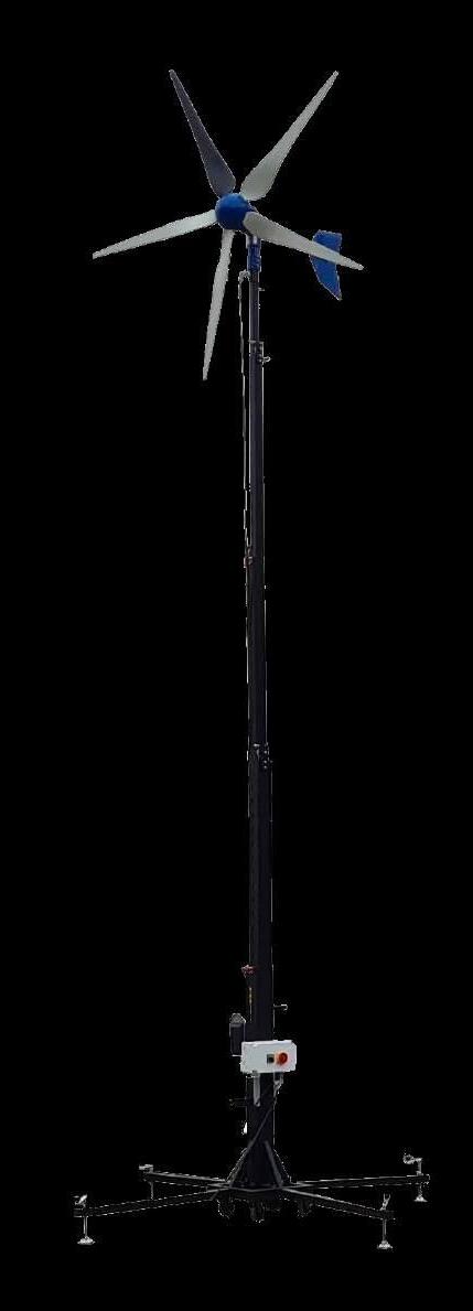
PST2290 Wind Power Module

The PTG2290 Wind Power Module models the inherent principles, functions and challenges in the different stages of a wind power plant project. This includes both the operation of the individual wind turbine, as well as the connection of the plant to an electrical grid. It promotes hands-on experience in order to understand and overcome the challenges when incorporating modern renewable energy power plants into classic grid topologies.
The module includes an actual smallscale wind turbine that conveys the fundamental physical, mechanical and electrical principles when harvesting electrical energy from the wind. It is mounted on a 3 m mobile and foldable mast unit that allows quick and easy setup and repositioning at an optimal location in accordance with the local wind conditions.
Weather independent simulation is also made possible by a fully programmable variable three phase power source, integrated into the PTG2290 Wind Power Module. This allows full control over wind conditions even when the weather is calm, maximizing the efficiency of student lab time.

Technical Specifications
Wind turbine type Vertical, Upwind
Additionally, a variable three phase electrical power source is integrated into the PTG2290 Wind Power Module, thus allowing the weather independent simulation of varying wind conditions and therefore maximizing the efficiency of student lab time.
Electrically, the module operates with a three phase permanent magnet alternator (PMA) connected to a three phase grid-tie inverter and includes all the necessary measuring, safety and display equipment for the operation of the wind power plant and execution of the provided experiments.


Aside from the three phase electrical data (voltagecurrent, active and reactive power as well as power factor), the data collected from the and included outdoor sensors on for wind speed, and wind direction, as well as air temperature and air pressure is displayed, logged and accessible for export.
The PST2290 Wind Power Module can function as stand alone equipment but can also easily be integrated into the Terco PTG and PST power system models and corresponding SCADA systems.
Weight
Windmill 32 kg
Mast 95 kg
Dimensions
Windmill 1120 x 420 x 430 mm
Mast 1000 x 1000 x 400 mm
23 www.tercosweden.com export@terco.se +46 8 506 855 00
Rated
Max
Rated
750
Start-up wind speed 6 m/s Rated wind speed 12 m/s Survival wind speed 50m/s Rotor diameter 1.96 m Swept area 3 m2 Generator 3-phase PMA Grid-tie inverter type Gridtie inverter type 3-phase Rated power 5.5 kW
power 1000 W
power 1 200 W
rotation speed
rpm
PST2250-150 TERCO SCADA System
Complete Laboratory Control and Monitoring System for the TERCO Power System
Simulator PST 2200 including General Electric iFix Software package and computer
iFIX is a superior proven real-time information management and SCADA solution, which is open, flexible and scalable. It includes impressive, latest generation visualization tools, a reliable control engine, and more.

Full system overview is provided via a tripple screen solution including user-selected page location.
As never before, this best in class software allows you to perform better analysis and leverage more reliability, flexibility, and scalability .
Complete access rights management and administration for both groups and individuals from Viewing Only to Full Control access of selectable modules.
Easy installation of additional power system modules for trouble-free future upgrades. Presentation of user-selected Trend Data for intuitive power system monitoring over time.
It is possible to connect multiple clients. Consequently multiple students can work simultaneously.
With the TERCO SCADA system, synchronization can be performed remotely at multiple points in the PST. Key parameters such as voltage and frequency are presented in real-time during the easy synchronization process.
All instruments, isolators and breakers, are indicated on screen even when operated from front panels. This facilitates for the teacher to study the work of the students without interfering.
The Equipment comprises:
A. Advanced Measuring System connected on a local bus for instrumentation which through SCADA will reflect the real environment.
B. PLC’s to operate Isolators and Circuit Breakers together with auxiliary contactor functions for external connections.
C. PLC’s to control Generator Speed/Frequency and Voltage.
D. Corresponding Software with Development Version License (Not only run-time).
Industrial SCADA system development version.
Features:
Indication Modules:
• Isolator and Breaker Status Control.
• Alarm Indications from Protection Relays.
• Extraction and Visualization of Disturbance Records
Full access to protections relays including parameter setting and Disturbance Records possible via a standard web browser.
It is possible to view important analogue current and voltage sinus waveforms in a suitable graph, together with protection’s binary input and output status for indepth fault analysis after such an event has occurred. Voltage and current vectors is presented alongside the graph with the possibility to scroll to any timepoint for simultaneous waveform and vector comparison.
Monitoring of system-wide power network characteristics occur via several industrial three-phase instruments, each comprising 20 parameters, such as:
• Voltage (ph-ph, ph-N, mean ph-ph, mean ph-N)
• Current (phases and mean) which enables the possibility to monitor non-symmetrical behaviour
• Active, reactive and apparent power (both phases and mean), cos phi etc.
24 www.tercosweden.com export@terco.se +46 8 506 855 00
To provide the best possible overview the system is delivered with 3 screens
.... continuation
PST2250-150 TERCO SCADA System

Additional characteristics are monitored via single phase instruments, such as:
• Generator exitation current
• Voltage meters for bus bars
Remotely Controlled Modules:
• Motor (Turbine) Speed
• Generator Voltage
• Synchronization
• Loads
• Circuit Breakers
• Isolators
• Alarm Resetting
• Protection relay parameter settings
• Fault injections
Others:
• All Isolators and Circuit Breakers are interlocked by PLC’s, to prevent faulty operation orders
• Replicates all PST 2200 System main module configurations
• Easily visualization of control and monitoring images
• Event logging (Alarm history)
The price includes the following:
• Complete hardware as above, software and software license
• Suitable high specification PC with 3 wide screens
• Manual covering essential descriptions
• Installation, commissioning and 1-2 days Basic Teacher Training at site by TERCO Engineer
Measurements:
Three screens per SCADA System as standard.
Each screen
Cubicle WxHxD 620x360x400 mm
Weight 5 kg
Computer (one computer per SCADA System):

Cubicle WxHxD 170x400x450 mm
Weight 6 kg
The dimensions and weights can vary slightly with any new screen and computer.
From the PST SCADA application (or Internet Explorer) the Protection Units can be accessed and configured by means of the ABB WHMI application (integrated in the Terco SCADA system). Below an example from the main page of a protection unit when a trip has occurred:

25 www.tercosweden.com export@terco.se +46 8 506 855 00
PST2252-1 SCADA Student Terminal
PST2252-1 SCADA Student Terminal contains:
• Suitable PC with wide screen
• Software license and communication card for connection to Master PC
• Necessary cables and components for connection to master PC in the same room
One SCADA Terminal can be able to control the whole PST system like the Master PC with the possibility to limit rights from Full Administrator Control to View Only Access.


This choice should be set from the Master PC via access rights management console.

Student Terminal requires SCADA iFix Master. Up to 64 students Terminals can be connected.
Full access to protections relays including parameter setting and Disturbance Records should be possible via a standard web browser.
It should be possible to view important analogue current and voltage sinus waveforms in a suitable graph, together with protection’s binary input and output status for in-depth fault analysis after such an event has occurred.
Voltage and current vectors should be presented alongside the graph with the possibility to scroll to any timepoint for simultaneous waveform and vector comparison.
Measurements
Screen
Cubicle WxHxD 620x360x400 mm
Weight 5 kg
Computer
Cubicle WxHxD 170x400x450 mm
Weight 6 kg
The dimensions and weights can vary slightly with any new screen and computer.
26 www.tercosweden.com export@terco.se +46 8 506 855 00
PST-Inst 1 Installation and Teacher Training
The installation is about 5 days and includes:
• Installation: TERCO presumes all necessary wiring and foundation to be ready according to instruction from TERCO prior to arrival of TERCO representative.
• Final Designation of Modules
• Electrical Internal Connection
• Electrical Installation to Main Supply
• Testing of Individual Modules
• Final Testing of the whole system.
All equipment packed in original crates. Unpacking are to be done together with TERCO representative.
The installation requires the support of one of your technicians.

Basic Teacher Training:
The proposed installation covers at the same time training with the system and presumes that the teachers are well familiar with electric power, theoretically and practically.
More comprehensive courses can be arranged at site or in Sweden and they can be tailor made according to customer requirement.
The training covers:
• Use of manual
• Technical Structure of the System including explanation of layout, external connections, internal connections and communication
• Starting, stopping and running the system for normal operation
• Operating the measuring systems
• Operating the CB and Isolators logical interlocking systems
• Performing a choice of experiments
• Performing a choice of network configurations
• The concept of synchronizing to a second generator or power source (if applicable)
• Fault Simulation Basic Service
27 www.tercosweden.com export@terco.se +46 8 506 855 00

28 www.tercosweden.com export@terco.se +46 8 506 855 00 ORDER DETAILS POWER SYSTEMS SIMULATOR Order code Description Pcs Level 1 Pcs Level 2 Pcs Level 3 Page PST2210-IED1 Power Plant Module, IED Level 1 1 8 PST2210-IED2 Power Plant Module, IED Level 2 1 8 PST2210-IED3 Power Plant Module, IED Level 3 1 8 PST2221 Transmission Lines Module 1 1 1 11 PST2222 Distribution Lines Module 1 1 1 14 PST2230-IED1 Receiving Substation Module, IED Level 1 1 12 PST2230-IED2 Receiving Substation Module, IED Level 2 1 12 PST2230-IED3 Receiving Substation Module, IED Level 3 1 12 PST2240 Load Module 1 1 1 15 PST2250-150 Terco SCADA System Master Module, 3 screen solution 1 1 1 24 Additional Modules PST2212 Mobile Additional Generator Module 1 1 1 17 PST2280 Power Factor Control Unit 1 1 1 16 PST2231 Power Grid Switchgear Module 1 1 1 19 Optional (one unit ofeach) PST2252-1 Terco SCADA System Student Module, 1 screen solution 1 1 1 26 Renewable Power modules PST2290 Wind Power Module 1 1 1 23 PST2291 Solar Power Module 1 1 1 21 Installation and Teacher Training PST-Inst 1 Installation and Basic Teacher Training 1 1 1 27 Ref. 101,102,103
Terco reserves the right to make changes in the design and modifications or improvements of the products at any time without incurring any obligations
Section
PTG2000 Modular Power System
• Prwer Generation
• Transmission
• Power Grid System
The PTG2000 is a miniature system of production and distribution modules that can fit on a few meters of table surface. Each module itself can be studied. Together, the modules form an easy-to-manage, educational and comprehensible lab for controlling electrical energy.


2
PTG2000 General Description
The system consists of equipment that together form a mini power system showing how the power system works from production to consumer. The electric power system has two voltage sources consisting of synchronous generator and one from the existing power distribution network.
Furthermore, one or more transformers can be used to connect the generator and load points to the mains. The switchgear has dual buses and three feeders for incoming and outgoing lines.
The system can be connected to renewable energy sources (solar and wind) via a grid inverter. At this point, it is also possible to connect three or single-phase loads.
The unit is equipped with a large graphical Human Machine Interface (HMI) with a single line diagram.
Control, monitoring and parameter setting can be performed either from the HMI or from a PC by means of the standardized Ethernet interface.

The PTG1450 Line Multi Protection Trainer is equipped with the fully IEC61850 compliant ABB protection REF630 which is one of the most modern and sophisticated protection units in the product family of Intelligent Electronic Devices (IEDs).
The use of a highly advanced IED enables great possibilities to perform a wide range of laboratory experiments. This unit is intended for advanced training in modern line distance protection technology.
Features
• Multiple Generators are possible. Motor 2.2 kW, Generator 1.2 kW
• Active Load Sharing
• Grid System
• Colour coded power inlet / outlets for easy recognizing


Power supply and communication of modules
Local Area Network.
The modules Power Supply can be dasychained so that only one Power outlet is required
Every Module has two 1A fuse for Power Supply of the Module
• Mimic diagrams on the panels
• Solar/Wind Simulation 0,3 kW
• Basic and Advanced Relay Protection
• Power Factor Control of Transmission Lines
• Fully IEC61850 compliant ABB Relays

Colouring of safety connections
Note the difference in colour marking of phases and neutral conductors according to International Standards
30 www.tercosweden.com export@terco.se +46 8 506 855 00
EU ASIA, Middle East Brown Black Grey Blue Red Yellow Blue Black
Power System Overview

MAIN LINE & PROTECTION
TRANSFORMER & PROTECTION
π Line page 11
Mobile Motor / Generator Unit page 8,9
Line Multi Protection page 12
Differential Realy Protection page 13
Busbar page15


LAN network for:
• SCADA Control & monitoring


• Disturbance Record Analysis
• via PC
RENEWABLE ENERGY


Renewable Power Interface page 15
AC Meters page20
π Line page 11
Transformer page 10
SCADA Module page 18

CONSUMER
Ind. load page14
π Line page 11
Power Factor Control page 16
Res. load page 14
Fault Connection page 17
π Cable Line page 11
Cap. load page 14
31
G G
LINE
Content in PTG2000 Level 1 with Variable Transformer and Connection Box
MV1103 Variable Transformer 3-phase
MV1429 Connection Box / Terminal Board

PTG1965 Transformer Module

PTG1521 Transmission HV OH-Line 230 kV, 100 km
PTG1523 Transmission HV OH-Line 35 kV, 20 km
PTG1455 Differential Relay Module
PTG1570 Fault Connection Module
PTG1560 Resistive Load Module 400V, 1,5 kW in 15 steps


PTG1561 Inductive Module 400V, 2,5 kVAr in 15 steps
PTG1562 Capacitor Load Module 400V, 2,8 KVAr in 15 steps
PTG1939 AC Power Energy Meter

MAT220118 Digital Multimeter
MAT220350 Digital Clamp Meter AC / DC current

MV1801-HF Flex Set 200 pc Safety Leads 5 colours

MV1904 Flex Stand 15
PTG2000 Level 1, 2 and 3 are examples of standard setup. For more information about content and setup of your own Laboratory, please contact us.
32
12 1 1 2 3 4 5 6 9 7 8 12 11 10 14 13
3 5 9 7 8 10 4 6 11 11 2 15 14
Content in PTG2000 Level 2 with Mobil Motor/Generator Module
PTG1561 Inductive Module 400V, 2,5 kVAr in 15 steps
PTG1562 Capacitor Load Module 400V, 2,8 KVAr in 15 steps
PTG1939 AC Power Energy Meter
MAT220118 Digital multimeter
MAT220350 Digital Clamp Meter AC / DC current
MV1801-HF Flex Set 200 pc Safety Leads 5 colours MV1904 Flex Stand
PTG2000 Level 1, 2 and 3 are examples of standard setup. For more information about content and setup of your own Laboratory, please contact us.

33 www.tercosweden.com export@terco.se +46 8 506 855 00
1 2 3 4 5 6 9 7 8 12 11 10 14 13
PTG1965
PTG1521 Transmission HV OH-Line
kV, 100 km PTG1523 Transmission HV OH-Line
PTG1305 Mobil Motor / Generator Module
Transformer Module
230
35 kV, 20 km PTG1455 Differential Relay Trainer PTG1570 Fault Connection Module PTG1565 Double Busbar Module with 4 feeders PTG1560 Resistive Load Module 400V, 1,5 kW in 15 steps
15 12 9 7 8 10 4 6 1 2 3 5 7 11 11
14 13 14
Content in PTG2000 Level 3 Extended and Advanced System
PTG1305 Mobil Motor / Generator Module
PTG1965 Transformer Module
PTG1521 Transmission HV OH-Line 230 kV, 100 km
PTG1523 Transmission HV OH-Line 35 kV, 20 km
PTG1522 Transmission Cable MV Line 11 kV, 5km
PTG1450 Line Multi Protection Trainer
PTG1455 Differential Relay Trainer
PTG1570 Fault Connection Module
PTG1560 Resistive Load Module 400V, 1,5 kW in 15 steps

PTG1561 Inductive Module 400V, 2,5 kVAr in 15 steps
PTG1562 Capacitor Load Module 400V, 2,8 KVAr in 15 steps
PTG1565 Double Busbar Module with 4 feeders
PTG2291 Solar Power Module (incl. stand for outdoor use)
PTG2290 Wind Mill Module (incl. Wind Mill for outdoor operation)
PTG1439-405 Power Factor Control Module
PTG1939 AC Power Energy Meter
MAT220118 Digital Multimeter
MAT220350 Digital Clamp Meter AC / DC current
PTG1631 SCADA System
MV1801-HF Flex Set 200 pc Safety Leads 5 colours
MV1904 Flex Stand
PTG2000 Level 1, 2 and 3 are examples of standard setup. For more information about content and setup of your own Laboratory, please contact us.
34
17
21 20 19 16 18 17 1 2 3 4 5 6 9 7 8 12 11 10 14 13 15
1 2 6 5 7 8 3 4 9 10 11 3 12 12 15 19 16 16 13 20 18 13 14 20
PTG1305 Mobile Motor / Generator Unit
PTG1305 Mobile Motor / Generator Unit
A standard laboratory for power transmission normally consists of one or two generators, which are connected to one or more transmission links which finally reach transformers, distribution units and loads.

For example, here can be seen turbine/generators in parallel on the same busbar, a synchronous machine used as a synchronous compensator in the middle of a line, a single generator unit and a heavy group of generators.
Energy transfer, load shedding, static and dynamic stability at disturbances as well as sophisticated protection schemes can be studied under realistic forms. Not to forget compensation possibilities.
Power and current paths in grid networks are complicated. The TERCO system will give understanding for these problems. Wide range of flexibility is achieved by the mobile generator station / synchronous alternator (compensator) PTG1305.Two sets of PTG1305-405 can operate as described or work in parallel.
Modes of Operation
PTG1305-405 can also be used to compensate for system power characteristics (active and reactive) via turbine speed and generator magnetisation.
Technical Specification
Power Supply: Voltage 380-415 V AC 3-ph
Frequency 50 Hz/60Hz
Max current 16 A
Turbine/AC-machine freq.drive:

Armature/stator Volt 323-528 V AC Frequency 47-63 Hz Armature/stator current 3.4 A Input current 5.9 A
Rated output current 4.0 A
Rated output capacity 3.2 kVA
Speed 0-1800 rpm
Speed control/ Speed 0-1800 rpm
Active power control: Frequency converter, electronic current limit setting, start- and stop ramps.
Feedback systems Manual frequency setting. Automatic/Constant setting
Field current supply Integrated
Synchronous generator:
Armature volt 0-140 / 240 V AC
Power 1.2 kVA
Cos φ 0.8
Field volt 0-230 V DC
Voltage control/
Reactive power control PWM min. ripple-converter, electronic current limit setting
Feedback systems Manual voltage setting. Automatic/Constant setting. Separate voltage feedback
35
The Mobile Motor / Generator Module is equipped with Local Area Network communication for monitoring via PTG1631 SCADA Module. Relevant faults can be connected for troubleshooting exercises via PTG1570 Fault Module
Instruments:
AC-machine freq.drive (Turbine simulator)
Parameters and indications selected by 4-lines display in HMI-unit for example:
• Frequency setpoint 50Hz
• Stator Electric Frequency 50Hz
• Actual motor speed (from encoder) 1500 rpm at 50Hz, 1800 rpm at 60Hz
• Motor current 2,20 A
• DC-interlink voltage 520 V
• Speed control potentiometer (=frequency control)
• Feedback selector (Auto/ Man)
AC-machine M/G
• Armature voltage
• Voltage selector switch
• Armature current
• Voltage control potentiometer
• Feedback selector (Auto/ Man)
• Field current ammeter
Synchronizing device
• Synchronizing instrument
• Double voltmeter Du
• Double frequency meter Df
• Synchronizing switch
• Automatic or manual synchronizing
Auxiliary
• Machines mounted on machine bed with Slid rails.
• Control panel integrated with machines to one mobile unit.
• Laboratory connections by 4 mm safety plugs. Possibilities of connecting different types of step-up transformers as well as other instruments and protections.
Dimensions 1550 x 800 x 1200 mm
Weight 200 kg (approx.)
36 www.tercosweden.com export@terco.se +46 8 506 855 00
Product no Power Supply Synchronous Generator PTG1305-405-235 400V 3-ph, 50Hz 230V 3-ph, 50Hz PTG1305-406-236 400V 3-ph, 60Hz 230V 3-ph, 60Hz PTG1305-405-405 400V 3-ph, 50Hz 400V 3-ph, 50Hz PTG1305-406-406 400V 3-ph, 60Hz 400V 3-ph, 60Hz
Voltage and frequency variants
Transformer
PTG1965 Transformer Module
Between the grid and generator station connects a generator. The transformer allows the user to configure the transformer with different vector groups such as Dyn / Yyn and so forth.
Technical Specifications
Power Supply: 1-ph 220 - 240 V, 50 - 60 Hz
Three-phase: 2 kVA, 50-60 Hz
Primary: 3 x 230V D, 3 x 400V, Y
Secondary: 3 x 380-400-420V, y
Secondary current: 2.9A
No load current: 0.25A
Uk: 3.7%
Losses: Po=40W, Pcu=107W
Vector group: Selectable
Dimension: 560 x 420 x 205 mm
Weight: 48 kg
PTG1939 AC Power Energy Meter
PTG1939 AC Power Energy Meter is a practical solution for the study of 1, 2 and 3-Phase AC power systems up to 500VAC/10A.


The Power Energy Meter enables the measurement and visualization of a wide range of parameters in the study of symmetrical as well as non-symmetrical networks, such as:
• phase voltages
• phase-to-phase voltages
• line currents
• mean three-phase current
• mean three-phase voltage
• mean phase-to-phase voltage
• three-phase active
• reactive and apparent powers
• mean three-phase power factors.
The visualization of parameters is distributed over several pages (default preset to display five pages) where each page simultaneously displays four parameters.
PTG1939 AC Power Energy Meter
Technical Specifications
Power supply 220-240VAC, 50/60Hz
Measurement ratings:
Voltage / Current 500VAC max / 10AAC max
Reactive / Active Power 5 kVAr / 5 kW Cos Phi 0-1-0
Communications:
Serial interface RS485
Transmission protocol Modbus RTU8N2
Baud Rate 19200kB
Dimension 255 x 205 x 335mm
Weight 10kg
37 www.tercosweden.com export@terco.se +46 8 506 855 00
PTG1520-1523 Transmission / Distribution OH Line Modules


PTG1522
The Transmission Lines have scaled down 3-phase OH transmission lines with different values. For each Line it is possible to change and combine impedance elements to constitute other Overhead Lines (OH) High Voltages (HV) levels.
On the request other line values are possible to order.
All models have inductors, capacitors and resistors designed to withstand overload and surges for dynamic as well as for static experiments.
All parameters of the transmission models can be changed easily by both internal and external combinations, together with the possibilities of arranging the models in series, parallel or in grid networks.
Each line model consists of a three-phase pi-link and an earth link.
A safety switch is incorporated on the backside to ensure earthing of the Module
PTG1520,-1521,-1523
With our Transmission Line Modules, we have a unique combination of HV-lines, Medium-Voltage lines, OH-distribution Voltage lines and Distribution Voltage cables which will enable studies of the typical parameters and characteristics within the four main groups of AC-power transmission and corresponding need of compensation.
It is possible to isolate/separate the different R, L, and C characteristics of each line for individual analysis.
Relevant errors can be programmed for troubleshooting exercises via PTG1570 Fault Module
Technical Specification
Power Supply: 1-ph 220 - 240 V, 50 - 60 Hz
Power bus: 3-phase 400V AC/ 2A with 4 mm safety connectors.
Dimension: 560 x 420 x 205 mm
Weight: 15 kg
Terco reserves the right to make changes in the design and modifications or improvements of the products at any time without incurring any obligations
38 www.tercosweden.com export@terco.se +46 8 506 855 00
PTG1520 OH-HV π-link 77 kV 13 MVA 136 km PTG1521 OH-HV π-link 230 kV 110 MVA 100 km PTG1522 Cable MV π-link 11 kV 5 MVA 5 km PTG1523 MV-HV π-link 33 kV 20 MVA 20 km
Protective Modules - Fully IEC 61850 compliant
PTG1450 Line Multi Protection Module
The PTG1450 Line Multi Protection Trainer module is intended for advanced training in modern line distance protection technology.
It is equipped with the fully IEC61850 compliant ABB protection REF630 which is one of the most modern and sophisticated protection units in the product family of Intelligent Electronic Devices (IEDs).
REF630 is designed for protection of transmission and distribution networks.
The use of a highly advanced IED enables great possibilities to perform a wide range of laboratory experiments.
Relevant faults can be connected for troubleshooting exercises via PTG1570 Fault Module.
General Features
• Colour coded power inlet- and outlets for easy recognition of each phase.
• Mimic diagrams of the circuit along with large clear symbols printed on the front panel
Power bus circuit breaker switch:
• A two state switch (ON/OFF) with LED indication of CB (Circuit Breaker) status.
• Internal circuitry prevents operation of the CB during an unacknowledged trip.
Trip reset button:
• Button for quick reset of LEDs and acknowledgement of a trip.
• Control, monitoring and protection integrated in one IED
• Fully IEC 61850 compliant.
• Four independent parameter setting groups.
• Large HMI with single line diagram.
• RJ-45 interface for communication with PC.
• Protection and Control IED Manager PCM600: Advanced software for configuration and parameter setting.
The protective relay REF630 used in PTG1450 enables the student to learn and explore how to protect a varity of different power line configurations from various fault conditions.

Technical Specification .
Power Supply: 1-ph 220 - 240 V, 50 - 60 Hz
Possible to supply a compatible device with power (at page 3)
Power bus: 3ph, 400VAC, 2A
Dimension: 560 x 420 x 430 mm
Weight: 37 kg
Protective earth: one 4mm safety connector for external components at the rear of the unit.
REF630 Important Protection functions
• Capable of a 5 zone full-scheme high-speed line distance protection with mho*), bullet and quadrilateral characteristics.
• Three stages of over-current protection (Low, high and instantaneous)
• Directional earth-fault protection
• Over-voltage protection
• Over-power protection (configurable direction)
*) In order to retain dependability and security in cases of close-in faults when the loop voltage is zero, mho distance elements use cross-phase and/or memory polarization
Full access to protection relays including parameter setting and Disturbance Records is possible via a standard web browser.
It is possible to view important analogue current and voltage sinus waveform vectors in a suitable diagram, together with protection binary input and output status for in-depth fault analysis after such an event has occurred.
SCADA ready for remote control of Circuit Breaker and Trip Reset via HMI
39 www.tercosweden.com export@terco.se +46 8 506 855 00
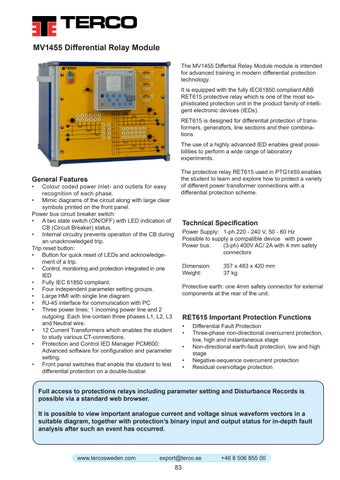
PTG1455 Differential Relay Module
The PTG1455 Differtial Relay Module module is intended for advanced training in modern differential protection technology.
It is equipped with the fully IEC61850 compliant ABB RET615 protective relay which is one of the most sophisticated protection unit in the product family of intelligent electronic devices (IEDs).
RET615 is designed for differential protection of transformers, generators, line sections and their combinations.

The use of a highly advanced IED enables great possibilities to perform a wide range of laboratory experiments.
Relevant faults can be connected for troubleshooting exercises via PTG1570 Fault Module.
General Features
• Colour coded power inlet- and outlets for easy recognition of each phase.
• Mimic diagrams of the circuit along with large clear symbols printed on the front panel.
Power bus circuit breaker switch:
• A two state switch (ON/OFF) with LED indication of CB (Circuit Breaker) status.
• Internal circuitry prevents operation of the CB during an unacknowledged trip.
Trip reset button:
• Button for quick reset of LEDs and acknowledgement of a trip.
• Control, monitoring and protection integrated in one IED
• Fully IEC 61850 compliant.
• Four independent parameter setting groups.
• Large HMI with single line diagram.
• RJ-45 interface for communication with PC
• Three power lines; 1 incoming power line and 2 outgoing. Each line contain three phases L1, L2, L3 and Neutral wire.
• 12 Current Transformers which enables the student to study various CT-connections.
• Protection and Control IED Manager PCM600: Advanced software for configuration and parameter setting.
• Front panel switches that enable the student to test differential protection on a double-busbar.
The protective relay RET615 used in PTG1455 enables the student to learn and explore how to protect a variety of different power transformer connections with a differential protection scheme.
Technical Specification
Power Supply: 1-ph 220 - 240 V, 50 - 60 Hz
Power bus: (3-ph) 400V AC/ 2A with 4 mm safety connectors
Dimension: 560 x 420 x 430 mm
Weight: 37 kg
Protective earth: one 4mm safety connector for external components at the rear of the unit.
RET615 Important Protection Functions
• Differential Fault Protection
• Three-phase non-directional overcurrent protection, low, high and instantaneous stage
• Non-directional earth-fault protection, low and high stage
• Negative-sequence overcurrent protection
• Residual overvoltage protection
Full access to protection relays including parameter setting and Disturbance Records is possible via a standard web browser. It is possible to view important analogue current and voltage sinus waveform vectors in a suitable diagram, together with protection binary input and output status for in-depth fault analysis after such an event has occurred.
SCADA ready for remote control of Circuit Breaker and Trip Reset via HMI
40
Loads
PTG1560 Resistive Load Module
The load can be changed in 15 steps with 100W / step at 400V. Totally 1500 W. The unit can be programmed for a typical load curve over 24 hours.

Power Supply: 1-ph 220 - 240 V, 50 - 60 Hz
Input Voltage: 3-phase 400V AC/ 2A with 4 mm safety connectors.
Dimension: 560 x 420 x 430 mm
Weight: 38 kg
PTG1560 consists of 2 units which can be split to optimize the bench top place.


PTG1561 Inductive Load
PTG1561 is housed in a metal cabinet with electrical data and symbols on the front panel. Both the 50 and 60Hz variants charge 1.5 kVAr and are Y-connected.
PTG1561 Inductive Load for 50 / 60Hz
Power Supply: 1-ph 220 - 240 V, 50 - 60 Hz
Current: 0.15-2.2A / 0.12-1.8 A
Input Voltage: 3-phase 400V 50Hz / 2A with 4 mm safety connectors
Dimension: 560 x 420 x 430 mm
Weight: 40 kg
PTG1561 consists of 2 units which can be split to optimize the bench top place.
PTG1562 Capacitor Load Module
PTG1562 is housed in a metal cabinet with electrical data and symbols on the front panel. Both the 50 and 60Hz variants charge 1.5 kVAr and are Y-connected.
PTG1562 Capacitive Load for 50Hz / 60Hz
Power Supply: 1-ph 220 - 240 V, 50 - 60 Hz
Current: 0.15-2.2A / 0.18-2.6A
Input Voltage: 3-phase 400V 50Hz / 2A with 4 mm safety connectors
Dimension: 560 x 420 x 205 mm
Weight: 15 kg
41 www.tercosweden.com export@terco.se +46 8 506 855 00
Power Components
PTG1565 Double Busbar Module
This unit is a double busbar module where the user has access to 4 feeders for incoming/outgoing power. Each feeder is connected to the two busbars through two isolators and one circuit breaker. Internal logic prohibits the user from incorrect switching (i.e breaking current with an isolator). This module can be used in the laboratory to assemble a larger power grid.
Relevant faults can be connected for troubleshooting exercises via PTG1570 Fault Module
Power Supply: 1-ph 220 - 240 V, 50 - 60 Hz
Power bus: 3-phase 400V AC/ 2A with 4 mm safety connectors.

Dimension: 560 x 420 x 205 mm
Weight: 10 kg
Fault Connection Module
All Load Modules are equipped with Local Area Network communication for monitoring and control via PTG1631 SCADA Module.

Relevant errors can be programmed for trouble shooting exercises via PTG1570 Fault Module
PST1570 Fault Connection Module
is a fault simulator with the ability to simulate many different types of variable short circuit and earth faults. The maintained / momentary switch allows safe and secure connection of permanent or instantaneous faults
Impedance errors can be connected individually, in parallel or in series.
PTG1570 is used together with Line Multi Protection Trainer and Differential Protection Trainer
Power supply: 1-ph 220 - 240 V, 50 - 60 Hz
Dimension: 560 x 420 x 205 mm
Weight: 15 kg
42 www.tercosweden.com export@terco.se +46 8 506 855 00
PTG1439-405 Power Factor Control Unit
General
With the Power Factor Control Module (PFC) you can minimise the currents caused by reactive losses of power thereby optimising the transfer of energy between generation and loading.

This is becoming more and more important today when “Saving energy” is vital in a world with focus on pollution and shortage of energy.
Field of application
Inductive or mixed inductive and resistive networks in need of compensation, for example when starting and running induction motors as in industrial applications.
Principles of operation
Depending on the power factor of the loading network a microprocessor will connect groups of capacitors. By measuring phase voltages and current the microprocessor will calculate how many capacitive groups that has to be connected and also in which combinations.
Electrical details
Number of 3-ph groups 6 capacitive
Power factor setting: 0 to 0.7
MV1439-235 nomial voltage 3 x 230V, 50-60 Hz
MV1439-405 nomial voltage 3 x 400V, 50-60 Hz
Nominal voltage : 3 x 400 V 50 – 60 Hz
Nominal power: 0 – 2 kVAr capacitive
PF-Controller: Automatic or manual Adjustable delay times, switching sequences and strategies.
Monitoring and Measurement on the controller:
Voltage, Current and Power factor
Switching modes: Linear and circular Indication lamps: Indication lamps for the capacitor groups which are connected
Physical design
The Power Factor Control Unit is housed in a sturdy apparatus box with a clear mimic diagram explaining how to connect the supplying net from the left to the right side where the network in need for power factor compensation is connected. Readings, parameters and sub parameters are indicated on the front of the controller. Other settings and programming than the defaults are simply performed from the keyboard and displayed on the controller front.
General data:
Power supply: 1-ph 220 - 240 V, 50 - 60 Hz
Dimension: 560 x 420 x 430 mm
Weight 24 kg
Typical Experiments with Terco PFC:
• The concept of active power, apparent power and reactive power
• The concept of power factor and cos φ
• The concept of measuring methods
• Start current settings (C/k)
• Delay times
• Efficiency and losses
• Linear and circular switching modes
• PF-Controller design and schematics
• Programming the controller
• PF-Controller and resistive/inductive loads
• PF-Controller and induction motor loads
• Control range limits
43 www.tercosweden.com
+46 8 506 855 00
export@terco.se
PTG2291 Solar Power Module

General
PTG2291 is a free standing module with the same form factor as the other modules.
PTG2291 is a generator station where the generator consists of three solar panels delivering three-phase power to the module that can further be tied to a grid.

The module simulates a solar farm, containing all necessary equipment such as solar panels, inverters, switchgear, protection modules and voltage transformation before interfacing the grid.
A Solar Farm provides a variety of switching equipment that handles control and switching of both AC and DC.
Technical Specifications
Electrical Data
General Data
Power Supply: 240V 3-phase, 10A. Each module connects 3 pole (L1, N, Earth)
Cubicle 560 x 420 x 430 mm
Weight 24 kg
Rear side I/O: 1 phase + N + PE 230V/50Hz protected by a Fuses
Photovoltic power in: 3 phase + N + PE 400V/50Hz (grid-tied) protected by a MCB and EF protection

DC- Switching
• DC CB Capable of switching the rated current remotely.
AC - Switching
• 6 x CB’s 3 pole breaking of current
Photovoltaic Module
The photovoltaic module consists of three solar panels framed in a sturdy Aluminum frame, designed to be mounted on ground or on a roof top. The panels together with the electrical equipment are all IP65 or higher classed, making them suitable for outdoor use in all weather conditions.
Panels Specification
3 x monocrystalline:
• Maximum Power (Pmax): 265W
• Short Circuit Current (typical A/lsc): 8.41
• Open Circuit Voltage (typical V/Voc: 37.7
Inverter
3 x micro inverter to convert the DC to AC. 250W / inverter, Grid-tied.
Measurements
Each panel incl.stand
Cubicle WxHxD 1650 x 990 x 120 mm
Dimension specifies panel folded down without wheels.
Weight 52 kg per panel
44 www.tercosweden.com export@terco.se +46 8 506 855 00
PTG2290 Wind Power Module
The PTG2290 Wind Power Module models the inherent principles, functions and challenges in the different stages of a wind power plant project. This includes both the operation of the individual wind turbine, as well as the connection of the plant to an electrical grid. It promotes hands-on experience in order to understand and overcome the challenges when incorporating modern renewable energy power plants into classic grid topologies.
The module includes an actual smallscale wind turbine that conveys the fundamental physical, mechanical and electrical principles when harvesting electrical energy from the wind. It is mounted on a 3 m mobile and foldable mast unit that allows quick and easy setup and repositioning at an optimal location in accordance with the local wind conditions.
Weather independent simulation is also made possible by a fully programmable variable three phase power source, integrated into the PTG2290 Wind Power Module. This allows full control over wind conditions even when the weather is calm, maximizing the efficiency of student lab time.
Technical Specifications
Additionally, a variable three phase electrical power source is integrated into the PTG2290 Wind Power Module, thus allowing the weather independent simulation of varying wind conditions and therefore maximizing the efficiency of student lab time.
Electrically, the module operates with a three phase permanent magnet alternator (PMA) connected to a three phase grid-tie inverter and includes all the necessary measuring, safety and display equipment for the operation of the wind power plant and execution of the provided experiments.
Aside from the three phase electrical data (voltagecurrent, active and reactive power as well as power factor), the data collected from the and included outdoor sensors on for wind speed, and wind direction, as well as air temperature and air pressure is displayed, logged and accessible for export.
The PTG2290 Wind Power Module can function as stand alone equipment but can also easily be integrated into the Terco PTG and PST power system models and corresponding SCADA systems.
Weight Windmill 32 kg
Mast 95 kg
Dimensions
Windmill 1120 x 420 x 430 mm
Mast 1000 x 1000 x 400 mm
45 www.tercosweden.com export@terco.se +46 8 506 855 00
Wind turbine type Vertical, Upwind Rated power 1000 W Max power 1 200 W Rated rotation speed 750 rpm Start-up wind speed 6 m/s Rated wind speed 12 m/s Survival wind speed 50m/s Rotor diameter 1.96 m Swept area 3 m2 Generator 3-phase PMA Grid-tie inverter type Gridtie inverter type 3-phase Rated power 5.5 kW
PTG1631 SCADA System
PTG1631 SCADA System Module includes an advanced and stylish industrial standard HMI where measurement data from throughout the power system is collected, logged and presented.

Power system characteristics can be monitored and investigated in real-time on attractive virtual instruments. Time-lapse data tracked and presented clearly in trend charts and values stored in the data logger can be saved and exported for further investigation at a later date. Clear indications of important system events help operators to understand the complicated relationships and balance required between modern components, in order to maintain a robust power supply.
PTG1631 SCADA System Module is designed to work with multiple PTG1939 Power Energy Meters. These measurement instruments provide information of over 30 3-phase parameters each and are connected via a LAN network.
The HMI can even be accessed and controlled remotely from a PC via a VNC Viewer. This allows for further presentation via projector, large-screen t.v. or other device
Power supply: 1-ph 220 - 240 V, 50 - 60 Hz
Dimension: 560 x 420 x 430 mm
Weight 17 kg
46
ORDER DETAILS POWER GENERATION AND GRID MODULAR SYSTEM Order code Description Pcs Level 1 Pcs Level 2 Pcs Level 3 Page MV1103 Variable Transformer, 3-phase 1 200 MV1429 Connection Box / Terminal Board 1 218 PTG1305-405 Mobil Motor / Generator Module 1 1 35 PTG1965 Transformer Module 1 1 1 37 PTG1521 Transmission HV OH Line 230 kV, 100 km 1 1 1 38 PTG1523 Transmission MV OH Line 35 kV, 20 km 1 1 1 38 PTG1522 Transmission Cable MV Line 11 kV, 5 km 1 38 PTG1450 Line Multi Protection Trainer 1 39 PTG1455 Differential Relay Trainer 1 1 1 40 PTG1570 Fault Connection Module 1 1 1 42 PTG1565 Double Bus bar Module with 4 feeders 2 2 42 PTG1560 Resistive Load Module 400 V, 1,5 kW in 15 steps 1 1 1 41 PTG1561 Inductive Load Module 400V, 2,5 kVAr in 15 steps 1 1 1 41 PTG1562 Capacitor Load Module 400 V, 2,8 kVAr, in 15 steps 1 1 1 41 PTG2291 Solar Power Module 1 44 PTG2290 Wind Mill Module 1 45 PTG1439-405 Power Factor Control Module 1 43 PTG1939 AC Power Energy Meter 2 2 2 37 MAT220118 Digital Multimeter 1 1 1 214 MAT220350 Digital Clamp Meter AC / DC current 1 1 1 211 PTG1631 SCADA System Module 1 46 MV1801-H Flex Set 200 Safety Leads 5 colours 1 1 1 221 MV1904 Flex Stand 1 1 1 222 Ref. 151,152,153
Technical specifications HMI Housing material: Powder-coated aluminum, Gray Screen: TFT-LCD 12”, 1280x800 px Class I (ISO9241-307) LED Backlight and Industrial dimming Resistive Touch Screen Full colour
Electrical Machines Laboratory
• Electrical Machines
• Drives
• Power Factor Control Wind Mill
For more than 50 years, Terco has developed and sold electrical machines for technical education. TERCO systems are today installed in hundreds of schools all over the world.

Through consultation, individual needs can be met with a customized package including hardware solutions and relevant study programs.
The test motors and generators have a power output of approximately 1 kW. This size of machines is such that :
• Standard instruments can be used.
• Safety precautions can be observed easily.
• It is possible to interchange the machines without using a crane or hoist.
• They represent typical characteristics for electrical machines.
• Prices are competitive.
Thanks to the top quality and robust construction of Terco products, they are able to withstand rough handling by young, unexperienced students.
With Terco Classic Machines it is possible to produce characteristics which are typical for machines with 6-8 kW ratings, partly because Terco Electrical Machines have a robust construction with a higher than normal iron and copper content.
This makes it possible to overload the machines more before reaching saturation. If you compare the weight of corresponding machines from other manufacturer you will see the difference.
Section 3
Notice - Explanation of Suffix at page 2
Important
Small machines 1 kW with characteristics as large
MV1028 DC Machine
(Motor and Brake Machine)
Complete with interpoles. This machine is used in test machine sets such as motors or generators, mounted on a 10 mm thick anodized Aluminum plate to be placed on the machine bed MV 1004.
General Data
MV1028-225
Generator 2.2 kW 1500 rpm
Motor 2.0 kW 1400 rpm
Excitation 220 V 0.8 A
Armature 220 V 12 A
Moment of inertia J = 0.012 kgm2
Dimensions 465 x 310 x 310 mm
Shaft height 162 mm
Weight 50 kg
MV1028-226
2.2 kW 1800 rpm
2.0 kW 1700 rpm
220 V 0.8 A
220 V 12 A
MV1028-226 and are designed for tests on 60 Hz networks.
MV1008-225 and -405 are designed for tests on 50 Hz networks. MV1008-226 and -406 are designed for tests on 60 Hz networks. DC machine MV1036-226 is designed for tests on electrical machines with 60 Hz ratings.
MV1006 DC-Machine
The machine has a shunt and a series winding and can be connected as shunt motor, series motor, compound motor, shunt generator, series generator or compound generator. MV1006 has also commutating poles (interpoles) which improve the characteristics of the machine.
General Data MV1006-225 MV1006-226
Excitation 220 V 0.55 A 220 V 0.55 A
The series winding has an extra terminal at 2/3 of the winding.
Moment of inertia J = 0.012 kgm2 (approx.)
Dimensions 465 x 300 x 310 mm, Shaft height 162 mm
Weight 45 kg
MV1008-225 and -405 are designed for tests on 50 Hz networks. MV1008-226 and -406 are designed for tests on 60 Hz networks. DC machine MV1036-226 is designed for tests on electrical machines with 60 Hz ratings.
MV1007-405 Induction Motor Slip Ring
The machine is a 3-phase slip-ring asynchrous motor with means to connect a rotor starter to be used for starting.Terminals on anodized front panel with symbols and electrical data.


General Data 50 Hz 60 Hz
Power 1.1 kW, 1.1 kW,
Speed 1440 rpm, 50 Hz 1680 rpm, 60 Hz
Star connection 380-415 V, 3.2 A 380-415 V, 3.2 A
Delta connection 220-240 V, 5.5 A 220-240 V, 5.5 V
Secondary 260 V, 3.0 A 260 V, 3.0 A
Moment of inertia J = 0.012 kgm2 (approx.)
Dimensions 465 x 300 x 310 mm, Shaft height 162 mm
Weight : 42 kg
MV1007-695 Induction Motor Slip Ring
As MV1007-405 but for 380-415 V 3-phase, Delta, 50-60 Hz
48
1.2 kW 1400 rpm 1.2 kW 1700
Shunt motor 1.0 kW 1400 rpm 1.0 kW 1700 rpm Series motor 1.0 kW 1150 rpm 1.0 kW 1400 rpm
Generator
rpm
Rotor 220 V 5.5 A 220 V 5.5 A
Important Notice
Explanation
-
of Suffix at page 2
MV1008 Synchronous Machine
The machine has a DC excited cylindrical rotor, operating on voltages up to 220 V DC (maximum excitation).
MV1008-235 and -405 are designed for tests on 50 Hz networks. MV1008-236 and -406 are designed for tests on 60 Hz networks.
MV1009-405 Induction Motor Squirrel Cage

MV1009-695 Induction Motor Squirrel Cage
As MV1009-405 but for 380-415 V 3-phase Delta. With this machine it is possible to do star/delta starts for 380-415 V lab voltage.
MV1009-385 Induction Motor Squirrel Cage
A
of 1.5 kW. Same design and electrical voltages as MV1009-405.

With Terco Classic Machines it is possible to produce characteristics which are typical for machines with 6-8 kW ratings, partly because Terco Electrical Machines have a robust construction with a higher than normal iron and copper content.
This makes it possible to overload the machines more before reaching saturation. If you compare the weight of corresponding machines from other manufacturer you will see the difference.
49 www.tercosweden.com export@terco.se +46 8 506 855 00
General Data MV1008-235 MV1008-236 (60 Hz) Synch. Gen. 1.2 kVA x 0.8 1.2 kVA x 0.8 Synch. Motor 1.0 kW 1500 rpm 1.0 kW 1800 rpm Star conn. 220-240 V 3.5 A 220-240 V 3.5 A Delta conn. 127-140 V 6.1 A 127-140 V 6.1 A Excitation DC 220 V 1.4 A 220 V 1.4 A MV1008-405 MV1008-406 (60 Hz) Synch. Gen. 1.2 kVA x 0.8 1.2 kVA x 0.8 Synch. Motor 1.0 kW 1500 rpm 1.0 kW 1800 rpm Star conn. 380-415 V 2.0 A 380-415 V 2.0 A Delta conn. 220-240 V 3.5 A 220-240 V 3.5 A Excitation DC 220 V 1.4 A 220 V 1.4 A Moment of inertia J = 0.012 kgm2 (approx.) Dimensions 465 x 300 x 310 mm, Shaft height 162 mm Weight 39 kg
General Data 50 Hz 60 Hz 4 pole machine 1.1 kW 1400 rpm 1.1 kW 1700 rpm Star (Y) 380-415 V, 2.4 A 380-415 V, 2.4 A Delta (D) 220-240 V, 4.1 A 220-240 V, 4.1 A Moment of inertia J = 0.0023 kgm2 (approx.) Dimensions 355 x 300 x
mm Shaft height 162 mm Weight 19
310
kg
4-pole motor
MV1054 is a modern torque meter based on the latest sensor technology. It comprises a magnetically based contactless torque sensor together with data acquisition and a display unit for torque, speed and shaft power. The sensor unit consists of a magnetically encoded torsion shaft with a magnetically based contactless sensor, together with a data acquisition unit with 15 bit resolution.

Torque measurement is performed/presented within the range -17.50Nm - +17.50Nm with exceptionally high accuracy including stand still torque as it is possible to lock the shaft with a specially attached bar.
Speed measurement is performed/presented within the range -3000- +3000rpm and the shaft power is calculated and presented within the range -5.50kW- +5.50kW

Technical Specifications
Nominal torque +/-17.50Nm
Max. mechanical torque 25Nm
Nominal shaft power +/-5.50kW
Nominal speed 0 - 3000rpm
Data acquisition protocol Modbus RTU 8N2
Baud Rate 9600kB/19200kB
Power supply 220-240VAC
1-phase, 50-60Hz
Sensor Unit Dimensions 200x190x146mm
Weight 5kg
Display Unit Dimensions 340x250x150mm
Weight 5kg

50 www.tercosweden.com export@terco.se +46 8 506 855 00
Terco reserves the right to make changes in the design and modifications or improvements of the products at any time without incurring any obligations
MV1054 Digital Torque-, Speed- and Shaft Power Meter
Measuring, Control and Data Acquisition for PC

Via the MV2658 PWM DC Control Module and the DC machine on the left, electric energy can be supplied or received for braking depending on which electric machine is being tested (right machine). Different lab setups can be selected via PC. All electrical and mechanical parameters can be logged for presentation in the PC.
The system contains of an combination of Measuring units, Control Units, Data Interface Module and Data acquisition software, enabling the user to observe, control, record and investigate relevant electrical data.

The software is designed to work with Terco Modbus instruments but may be set up to communicate with many Modbus devices.
Pre-configured experiment setups are included but the experiment presentation window is fully customizable, allowing the user to select available hardware, define data columns and set up graph parameters such as data sources and titles.
51 www.tercosweden.com export@terco.se +46 8 506 855 00
Graph presentation on PC
MV1943 Measuring and Control Module
The MV1943Measuring and Control Module integrates the communication interface functionalityof an USB to RS-485 adapter, with a 3-channel Modbus controlled 0-10V DC source in one compact unit.
Coupled with the MV2658 PWM Control unit, the MV1943 provides both communication between Terco measuring units and a PC, as well as simultaneous motor control.The 3-channel analog output is controlled via PC using the Terco Data Acquisition Software and enables additional futures such as fully automatic data acquisition.


Voltage output:
Channels 3
Channel output 0-10 V
Resolution 12 bit (2.5 mV)
Isolation 1500 Vac, Field to Logic Control system Terco MV2609 Control and Data
Aquisition Software
Dimensions 105mm x 147mm x 167mm
Weight 300g
MV1942 Data Interface Module
Technical Specifications
Communication:
Interface USB plug and play
Operating system 7/Vista/XP
Field interface RS485
Maximum devices 32 devices
Power source USB port
Power supply 220-240VAC, 50/60Hz
Communication:
Interface USB plug and play
Operating system 7/Vista/XP
Field interface RS485

Maximum devices 32 devices
Power source USB port
52 www.tercosweden.com export@terco.se +46 8 506 855 00
MV2609 Control and Data Aqusistion Software
Acquisition functions
Data is read into the PC via Modbus to USB link and presented in real-time in both tabular and graph form.
Data may be acquired using one of 4 possible acquirement modes: Single, Timed, Semi-Automatic and Full Automatic. The saved data can then be exported in Excel format for further investigation
Pre-configured experiment setups are included but the experiment presentation window is fully customizable, allowing the user to select available hardware, define data columns and set up graph parameters such as data sources and titles.

The software is designed to work with Terco Modbus instruments but may be set up to communicate with many Modbus devices.

MV2658 is an indispensable equipment in the electrical machines laboratory as it can be used in several different types of applications.
It can be used as a DC-Machine Drive in the range up to 1.2kW, a Generator Field Controller (VAr controller), or a Machine Brake Controller suitable with Terco equipment in the range up to 3.3kW
Technical Specifications
• PWM (16kHz) Based Excitation Voltage 0-260VDC.
• Selectable Current Limit Levels (front panel switch): 1.7ADC, 2.5ADC, 3.5ADC, 5.0ADC, 7.5ADC.

• Fixed Excitation Output 200VDC (for DC Drive application).
• PWM Controlled Excitation on the front panel control
• 0-100% Duty Cycle) or from the control input
• fully isolated, 0-10VDC = 0-100% Duty Cycle.
The control input can be used for instance in PC based control together with Terco DAQ software. (Optional analogue output interface unit necessary).

• Control Methods selectable between PWM Controlled Excitation Voltage Feedback and External Analog Voltage Feedback.
• Power Supply 220-240VAC, 50/60Hz
• Dimensions: 255 x 195 x 330mm
• Weight: 8kg (approximatly)
53 www.tercosweden.com export@terco.se +46 8 506 855 00
MV2658 PWM DC Control Module
Additional Machines
MV1015-405 Reluctance Motor
A reluctance motor starts as an induction motor, but operates normally as synchronous motor. A three-phase reluctance motor is self-starting when started as an induction motor. After starting, in order to pull it into step and then to run it as a synchronous motor, the reluctance motor has low rotor resistance. Some rotor teeth are removed to form a typical construction of a four-pole rotor.
General Data 50 Hz 60 Hz
Power 0.9 kW 0.9 kW
Speed 1500 rpm 1800 rpm
Delta Connection 220-240 V, 6.4 A 220-240 V, 6.4 A
Dimensions 360 x 300 x 310 mm
Shaft height 162 mm
Weight 25 kg
MV1015-695 Reluctance Motor
Same as MV 1015-235 but for 380-415 V, 3-phase, Delta.
MV1017-235 Induction Dahlander Motor
The winding of the Dahlander motor is arranged in a way, that by connecting in different formations 2 speeds are available. Switching can be performed using a cam switch or using contactors.

General Data
50 Hz 60 Hz
Power 0.9 / 1.3 kW 0.9 / 1.3 kW
Speed 1400 / 2800 rpm 1680 / 3310 rpm
Voltage D / YY 220-240 V D / YY 220-240 V 3-phase 3-phase
Current 5.4 / 4.7 A 5.4 / 4.7 A
Dimensions 355 x 300 x 340 mm
Shaft height 162 mm
Weight 17 kg
MV1017-405 Induction Dahlander Motor

As MV 1017-235 but for 380-415 V 3-phase
MV1505 Dahlander Switch
for Dahlander motor MV 1017, 16 A, 400 V, in metal case. Front panel showing symbols and technical data. Marking of terminals input R, S, T output 1 Ua, Va, Wa output 2 Ub, Vb, Wb

Dimensions 95 x 200 x 80 mm
Weight 1 kg
Important Notice - Explanation of Suffix at page 2
54 www.tercosweden.com
+46 8 506 855 00
export@terco.se
MV1018 Universal Motor

This is a commonly used motor in domestic appliances.It can be run on DC or AC 1-phase. The rotor is connected in series with the field winding and supplied via the commutator and brushes.


General Data
Power
1 kW DC at 2600 rpm, 0.4 kW AC
Speed 3000 rpm at 50 Hz
3600 rpm at 60 Hz
Voltage 220-240 V AC / DC
Current 8 A AC, 7 A DC
Dimensions 465 x 300 x 310 mm
Shaft height 162 mm
Weight 39 kg
MV1027 Synchronous Machine
The machine has a DC excited rotor with salient poles, operating on voltages up to 220 V DC (maximum excitation).
The advantages rising from this type of machine are measurements and characteristics corresponding to those of larger machines and the excitation voltage is readily available in most laboratories. An additional damping winding will counteract oscillations and also facilitate return to synchronism if the rotor falls out of phase.
The damping winding also allows the motor to be started as an asynchronous motor before energizing the field. Suitable excitation rheostat : MV1905.
MV1027-235 and -405 are designed for tests on 50 Hz networks. MV1027-236 and -406 are designed for tests on 60 Hz networks
MV1020 Induction Motor Capacitor Start
The capacitor assisted starting winding is disconnected from the circuit when the motor has built up speed, by means of a relay.
55
General Data MV1027-235 MV1027-236 MV1027-405 MV1027-406 Synch. Gen. 1.2 kVA x 0.8 1.2 kVA x 0.8 1.2 kVA x 0.8 1.2 kVA x 0.8 Synch. Motor 1.0 kW 1500 rpm 1.0 kW 1800 rpm 1.0 kW 1500 rpm 1.0 kW 1800 rpm Star conn. 220-240 V 3.5 A 220-240 V 3.5 A 380-415 V 2.0 A 380-415 V 2.0 A Delta conn. 127-140 V 6.1 A 127-140 V 6.1 A 220-240 V 3.5 A 220-240 V 3.5 A Excitation DC 220 V 1.4 A 220 V 1.4 A 220 V 1.4 A 220 V 1.4 A Moment of inertia J = 0.012 kgm2 (approx.) Dimensions 465 x 300 x 310 mm, Shaft height 162 m Weight 39 kg
General Data 50 Hz 60 Hz Power 0.75 kW 0.75 kW Speed 1425 rpm 1710 rpm Voltage 220-240 V 220-240 V 1-phase 1-phase Current 6.8 A 6.8 A Capacitors 310 uF 310 uF Dimensions 350 x 300 x 350 mm Shaft height 162 mm Weight 24 kg
MV1037 Induction Motor Cap. Start and Run
To obtain a higher starting torque, the starting winding has a capacitor connected in series. Continuous rating of start winding allows the circuit to remain the same during starting and running.
General Data 50 Hz 60 Hz
Power 0.75 kW 0.75 kW
Speed 1430 rpm 1715 rpm
Voltage 220-240 V 220-240 V
Current 5.4 A 5.4 A
Capacitors 25uF & 100 uF 25 uF & 100 uF
Dimensions 320 x 300 x 350 mm
Shaft height 162 mm
Weight 20 kg
MV1030-235 Induction Motor
2 Speed 2 Windings
This motor unlike MV 1017 which has only one set of windings, has 2 separate sets of windings for high and low speed.
Speed 930 / 1440 rpm
Current 4.7 / 6.0 A 4.7 / 6.0 A
Dimensions 450 x 300 x 340 mm
Shaft height 162 mm
Weight 24 kg
MV1030-405 Induction Motor
2 Speed 2 Windings
As MV1030-235 but for 380-415 V, 3-phase.
MV1031 Induction Motor
Thermistor Protected
This squirrel cage motor has a thermistor built into the windings for temperature control of the motor. Thermal relay MV 1032 is used in conjunction with this motor.


General Data 50 Hz 60 Hz
Power 1.1 kW 1.1 kW
Speed 1400 rpm 1700 rpm
Voltage 380-415/220-240 V 380-415/220-240 V 3-phase 3-phase
Current 3.0 / 5.2 A 3.0 / 5.2 A
Dimensions 340 x 300 x 310 mm, Shaft height 162 mm
Weight 22 kg
56 www.tercosweden.com export@terco.se +46 8 506 855 00
1-phase 1-phase
General Data 50 Hz 60 Hz
Power 0.8 / 1.0 kW 0.8 / 1.0kW
1120 / 1730 rpm
Voltage 220-240 V 220-240 V 3-phase 3-phase
MV1032 Thermal Relay
This is a control unit against overheating of motor MV1031. Most electrical machines withstand today 140ºC or more. However, it takes a long time to reach this temperature and the lab time is limited in the laboratory. Therefore we have chosen a cut off temperature at 60ºC for the experiments.
Dimensions 130 x 245 x 95 mm
Weight 1 kg
MV1047 Asynchronous Motor, 3-Phase Demonstration Set

The components of a type MT 63 induction motor are mounted on a wooden board. Only a screwdriver is needed to assemble the motor, and to permit repeated assembly and dismantling.


It is recommended to use 40V, 3-phase supply for testing the operation of the motor.

Dimensions 480 x 400 x 150 mm
Weight 7 kg
MV1010 Flywheel
The flywheel is stably journalled in 2 spherical bearings and secured to an Aluminum foundation. This ensures correct shaft height and lateral alignment. The flywheel is dynamically balanced and has a protective casing with 2 couplings. It is used in retardation tests for determining total friction losses, iron losses and short circuit losses at different excitation levels.
MV1010 is also suitable to use for tests with heavy load start.
Moment of inertia J = 0.406 kgm2
Dimensions 400 x 300 x 300 mm
Weight 56 kg
MV1905 Shunt Regulator
Used for field regulation of DC-machines MV1006, MV1028, MV1034 and for synchronous machines MV1008 and MV1027.
General Data
Power Supply

230V AC
Potentiometer-connected 440 ohms
Supply voltage
Max current
Dimensions
220 V DC
2 A
215 x 190 x 230 mm
Weight 3 kg
57 www.tercosweden.com export@terco.se +46 8 506 855 00
On the back of the MV1905 is placed a cooling fan
MV1903 Synchronizing Device
The equipment includes 1 zero voltmeter, 1 circuit breaker, 3 signal lamps and terminal bolts.

General Data MV1903-235 MV1903-405
Zero Voltmeter 2 x 140 V 2 x 220 V
Circuit Breaker 16 A 500 V 16 A 500 V
Synch. Lamps 130 V with resistor 220 V with resistor
Supply Voltage 220-240/127-140V 380-415/220-240 V 50-60 Hz 50-60 Hz
Dimensions 315 x 240 x 90 mm
Weight 3 kg
Other voltages can be supplied on request.
MV1004 Machine Bed
This strong, stable machine bed of anodized aluminum bars has rubber dampers on the underside to prevent transmission of vibration to the base. Clamps for mounting torque meter and machines are included


Dimensions 1500 x 300 x 65 mm
Weight 15 kg
MV1500 Load Switch

Three-pole, 16 A, 250 V- DC/440 V-AC,
Dimensions 95 x 200 x 80 mm
Weight 1 kg
MV1502 Reversing Switch
Suitable for 3-phase machine, 16 A, 500 V
Dimensions 95 x 200 x 80 mm
Weight 1 kg
MV1503 Star / Delta Switch
Suitable for 3-phase machine, 16 A, 500 V
Dimensions 95 x 200 x 80 mm
Weight 1 kg
58 www.tercosweden.com export@terco.se +46 8 506 855 00
MV1004 Machine Bed used with motors and generators.
Sectioned Motors
Not for connecting to the main and operation! The machines are sectioned about 90˚ allowing all the main components to be demonstrated clearly and in an educational way. Please note : It is not possible to do any practical experiments with the machines.
MV1006-C DC Machine
This machine is cut-away to show commutator, brushes, rotor, stator, windings, ball-bearings.


Rated power 1.0 kW
Dimensions 465 x 300 x 310 mm
Shaft height 162 mm
Weight 40 kg
MV1008-C Synchronous Machine
This machine is cut-away to show slip-rings, brushes, rotor, stator, windings, poles, ball-bearings etc.
Rated power 1.0 kW
Dimensions 465 x 300 x 310 mm
Shaft height 162 mm
Weight 35 kg
MV1007-C Induction Motor Slip-Ring
This motor is cut-away to show slip-rings, brushes, rotor, stator, windings, poles, fan, ball-bearings, etc.
Rated power 1.1 kW
Dimensions 440 x 300 x 350 mm
Shaft height 162 mm
Weight 37 kg
MV1009-C Induction Motor Squirrel Cage
This motor is cut-away to show rotor, stator, windings, poles, fan, ball-bearings, etc.
Rated power 1.1 kW
Dimensions 355 x 300 x 310 mm
Shaft height 162 mm
Weight 15 kg
59 www.tercosweden.com export@terco.se +46 8 506 855 00
MV1006-C
MV1007-C
MV1009-C
MV1915-C
Electric Torque Meter System, Analogue Dial incl. DC-brake / DC-drive Machine

A DC pendulum machine is freely suspended on plumber blocks and placed on an Aluminum foundation plate. The front panel is fitted with the necessary meters, controls and connection terminals. The torque is read on an analogue dial. The DC-machine has interpoles.
This analogue torque measuring system is very pedagogical and easy to handle. It is a reliable product which has been sold to many technical schools worldwide.
The picture shows MV1036 mounted on the machine bed MV1004 together with the tachometer generator MV1025 and the DC- test machine MV1006
MV1036-225 Electric Torque Meter System
Speed
0-4000 rpm
Ammeter 0-1 A (Field)
Ammeter 0-15 A (Arm.)
Shunt Control Potentiometer
Torque Grad. 0 – ± 25 Nm
Scale diam. 390 mm
Termination
Generator
Motor
4 mm terminals
2.2 kW 1500 rpm
2.0 kW 1400 rpm
Excitation 220 V 0.8 A
Armature 220 V 12 A
Dimensions 600 x 540 x 960 mm
Weight 90 kg
MV1036-226 Electric Torque Meter System
As MV1036-225 but following ratings.
Generator
Motor
2.2 kW 1800 rpm
2.0 kW 1700 rpm
Excitation 220 V 0.8 A
Armature 220 V 12 A
Weight 90 kg
Dim: 600 x 540 x 960 mm
DC machine MV1036-226 is designed for tests on electrical machines with 60 Hz ratings.
DC Machine MV1036-225 is designed for tests on electrical machines with 50 Hz ratings but can be used for 60Hz (higher speed but less torque)
MV1026-225 Electric Torque Meter System
Same as MV1036-225, but the drive motor has a double ended shaft, enabling to couple two machines at the same time for experiments and studying 4Q drives with one AC- and one DC drive/motor, Ward-Leonard system, cascade, etc. For central mounting on the machine bed. Designed for tests on electrical machines with 50 Hz ratings.
MV1026-226 Electric Torque Meter System
Same as MV1036-226 except that the drive motor has a double ended drive shaft, making it possible to couple two machines at the same time for experiments and studying 4Q drives with one AC- and one DC drive/ motor, Ward-Leonard system, cascade, etc. For central mounting on the machine bed. Designed for tests on electrical machines with 60 Hz ratings.
60 www.tercosweden.com export@terco.se +46 8 506 855 00
MV1004 MV1036 MV1025
MV1006
Terco reserves the right to make changes in the design and modifications or improvements of the products at any time without incurring any obligations

61 www.tercosweden.com export@terco.se +46 8 506 855 00 ORDER INFORMATION ELECTRICAL MACHINES LABORATORY Product no Description Pc Page Electrical Machines Laboratory. Experiment Voltage 3 x 400V or 3 x 230V (MV1300 is changeable) MV1028-225 DC-Machine, 2.2 kW complete with interpoles 220V 1 48 MV1006-225 DC-Machine 1 kW 220 V 50 Hz 1 48 MV1007-405 Induction Motor slip-ring 1.1kW 400/230V 50-60Hz 1.1kW 1 48 MV1008-235 Synchronous Machine, 230 V Y 50 Hz 1.2 kVA x 0.8 1 49 MV1009-405 Induction Motor Squirrel Cage, 400/230V 50-60 Hz 1,1 kW 1 49 MV1054 Digital Torque-, Speed- and Shaft Power Meter 1 50 MV1004 Machine Bed 1 58 MV2636 Starter AC- and DC-Motors, Classic 1 205 MV1300-405 Power Pack 3-ph, supply 400 V, out 230 V 1 200 MV1417 Terminal Board 1 218 MV1500 Load Switch, 3-pole 16A 1 58 MV1502 Reversing Switch 1 58 MV1503 Star-Delta Starter for 3-ph Machines 1 58 MV1905 Shunt Regulator 2 57 MV1903-235 Synchronizing Device 220-240 V 50-60 Hz 1 58 MV1003 Mobile Test Bench 1 220 MV1100-235 Load Resistor 3-ph 3.3 kW 1 204 MV1101 Load Reactor, 3-phase, 2.5 kVAr 1 204 MV1102 Load Capacitor, three-phase 2.8 kVAr 1 204 MV1830-HF Flex Set, 100 Safety Leads, Safety Plugs 1 221 MV1904 Flex Stand 1 222 Measuring and Data Acquistion MV1939 AC Power Energy Meter 1 210 MV1941 DC Measuring Unit 1 210 MV1943 Measuring and Control Module 1 52,28 MV2609 Control and Data Aquisition Software 1 53,209 Phase Cop 2 Phase Sequence Indicator 1 212 MV2658 MOSFET - PWM Module 1 53 Optional - Additional Machines and Torque Measuring, See page 56-60 Electrical Torque Meter System, Analogue Dial. incl. DC-brake / DC-Drive Machine See page 61 Ref. 200
Each delivery is packed according to export standard with correct marking and documentation


62 www.tercosweden.com export@terco.se +46 8 506 855 00
Training at the customer site or at TERCO Head Office in Stockholm, Sweden
DC-Drives
MV4207-1 DC-Motor Drive
Single-phase 4-Quadrant Rectifier, Three-Phase supply
Covers the latest development in DC-motor operation with analogue control. The equipment is designed to work according to different industrial environments. The drive has signal in- and outputs for connections to slave and/or master drives.
To cover a wider range of machines regarding voltage and speed the primary supply is taken from a standard 3-phase outlet which will supply the inverter bridges by 2-phase 400 V.

The design will enhance the possibilities of learning the theory and practice of understanding the operation of 4Q-drives for both single drives and the basic understanding of three bridges and their commutation.
The 4-Q-DC-Drive can be used in the conception of speed/torque control versus electro-machine theory. When braking, the energy is transferred directly to the supplying network by operating in all four quadrants.
Technical Specification
Input voltage: 3-phase 3 x 400 V + N + PE, 50-60 Hz
Input max current: 16 A, rotor inductance is included
Output voltage: 0-250 V DC
Output current: 0 - 12 A (max 16 A)
Nom. output power: 2 kW
Design: Tutorial where the 4Q industrial/ professional aspects are enhanced
Control: Manually operated Digital / Analogue
Front control parameters: 12
Feedback: DC-tacho or armature voltage
Built-in unit for immediate:
U+I+P signals, isolated, including MUX for oscilloscope.
Built-in protections and contactor relays
Dimensions 520 x 450 x 280 mm
Weight 23 kg
Standard Settings
12 Parameters are set manually:
Typically: Speed, Max Speed, Acc ram, Flux, Ret ramp, Ilim, Current/Speed proportional, Current demand in/ out, etc.
Floating switches and potentiometers are used to study step response and stability. The results of the dynamic response regarding voltage, current and immediate power can be studied fully isolated on a standard oscilloscope via the built in isolation amplifier and multiplexer.
Manuals
Consist of a theory section and an exercise section. The theory part explains for example general theory of the conditions for torque developed in an arbitrary machine, while the exercise section contains theory sections that are directly connected to the different experiments. The Manual consists of a complete binder together with an additional section , which will explain the UIP-unit (Voltage/Current/Power – unit) together with oscilloscope snap-shots showing different operation modes of the rectifier.

63 www.tercosweden.com export@terco.se +46 8 506 855 00
Manuals
Consists of a large quantity of experiments where related theoretical analyzes and explanations are performed in each experiment. Experiments furtheron covers basic operation and autotuning as well as more advanced operation directly from the drive keypad (operator station) or from PC where signal analysis also are possible by means of the chart recorder and the oscilliscope function.
MV4207-3 DC-Motor Drive
Three-phase 4-Quadrant Rectifier, Three-Phase supply covers the latest development in DC-motor PC-controlled operation with 6 pulse 4Q rectifiers. The equipment is designed to work according to different function principles and it is possible to explain several different types of DC-drives depending on the purpose and industrial environment from traction to paper- and steel mills.
Output current/voltage can be chosen to optimize torque/angular speed or to optimize other parameters by using a PC and the enclosed software. When braking, the energy is transferred directly to the supplying network by operating in all four quadrants. The field rectifier can be programmed manually or from a PC for optimized field control.
The 4Q DC Drive can be used in the conception of speed/torque control versus electro-machine theory. The equipment is also suitable for experiments and tests in industrial applications.

Technical Specification
Input voltage: 3-phase 3 x 400 V + N + PE, 50-60 Hz
Input max current: 16 A
Output voltage: 0 - 400 V DC
Output current: 0 - 12 A (max 16 A)
Nominal output power: 2 kW (max 3 kW)

Design: Tutorial but with the PC-controller industrial / professional aspects enhanced.
Control modes: Manually by front components, Manually by Operator Station, PC by RS 232 +”DELite”” + software
Front controls: Manually Digital > 20, Analogue > 4
Configuration: by PC or Operator Station
Self-tuning: by PC or Operator Station
Built-in protections and contactor relays
Dimensions 520 x 450 x 280 mm
Weight: 25 kg
Built-in Instruments and Oscilloscope Functions
The enclosed software will make it possible to configure the internal connections and operating principles by using a standard PC. On the screen it is possible to monitor 3 analogue instruments and edit a number of signals/parameters in parallel, which can be saved and printed. The number of parameters/tags possible to study exceeds 200.
Standard Settings and Advanced Settings
Most parameters are set by default but settings can also be done manually from the front controls.

Typically: Speed, Max Speed, Acc ram, Flux, Ret ramp, Ilim etc. Advanced settings, >200 parameters/tags, are performed by Operator Station on the unit, PC nearby the unit, connected to COM1 (COM2).

64
MV4206-1 AC-Motor Drive
AC-Drives
Covers the latest development in AC-motor operation with frequency converters. The equipment is designed to work according to different function principles and it is possible to explain several different types of frequency converters existing today.
4-Q-Drive: The Frequency Converter can be used in the conception of speed/torque control and electro-machine theory. The equipment is also suitable for experiments and tests in industries i.e. far beyond the area that the experiments show.

When braking, the energy is transferred by the DC-link and a brake chopper to a built-in load resistor.There is also an additional adjustable DC-injection brake.
Technical Specification
Input voltage: 3-phase 3 x 400 V + N + PE, 50-60 Hz
Input current: 16 A max

Output Power: 1.5 kW
Output voltage: 3 x 230 V
Max output current: 7 A
Max output frequency: 100 Hz
Choice of polygon: automatic
Breaking points: automatic
Internal switch frequency: 3 kHz max
Type of modulation: PWM sensorless vector
Intermediate DC-voltage: average value 300 V DC
Inverter bridge: MOSFET
Control voltage: +/- 10V DC analog, 0-24V DC Digital
Dimensions 520 x 450 x 280 mm
Weight 16 kg
Built-in Instruments Functions
The enclosed software will make it possible to configure the internal connections and operating principles by using a standard PC. On the screen it is possible to monitor 3 analogue instruments and scroll a number of signals/parameters in parallel, which can be saved and printed. The number of parameters/ tags possible to study exceeds 200.
Manuals
consist of a theory section and exercise section together with a software description. The theory part explains for example general theory of the conditions for torque developed in an arbitrary machine, while the exercise section contains theory that are directly connected to the different experiments. The instruction manual is enclosed as a complete binder together with a corresponding CD.
Standard Settings and Advanced Settings
Most parameters are set by default but settings can also be done manually from the front controls: Typically: Speed, Max Speed, Acc ram, Flux, Ret ramp, I-lim etc. Advanced settings: >200 parameters/tags, are performed by Operator Station on the unit, PC nearby the unit, connected via the comport.
65 www.tercosweden.com export@terco.se +46 8 506 855 00
Three-Phase supply, semi 4-Quadrant Drive frequency converter with MOS FET technique and a fixed intermediate DC-link.
MV2661 AC-Control

The MV2661 is an AC drive primarily designed for speed control of a 3-phase squirrel cage induction motor. Its purpose is to create a sinusoidal (or close to) 3-phase voltage that is connected to the stator of an AC-motor. The AC-drive controls the pulse width and the frequency of the supplied voltage and can therefore keep the motor running at constant speed although the mechanical load applied at the rotor shaft varies. The AC drive includes an autotune-function which automatically identifies the electrical and mechanical parameters of the connected induction motor.
The drive is capable of operating machines up to 1.5kW. It controls the output voltage 0-240V and frequency 0.1-600Hz. The maximum output current is 7.5A and the input current 15.7A (fuse size 15A).
It is mainly designed to operate together with Terco MV-machines, which are sized 1.1 – 1.5kW.
The AC CONTROL MV2661 is furtheron equipped with an internal brake chopper and an internal brake resistor which makes it possible to study short ramp time braking coarses.
All essential signals are connected to the front to make it possible not only to run typical experiments verifying the theory but also to make it possible to run the drive out of more advanced industrial aspects.
66 www.tercosweden.com export@terco.se +46 8 506 855 00 ORDER INFORMATION AC- AND DC-MOTOR DRIVES Additional quotation to Electrical Machines Laboratory Product no Description Pc Page DC-Drives MV4207-1 DC-Drive 1 63 MV4207-3 DC-Drive, Three-Phase supply 1 64 MV1024 DC-Tachogenerator incl. Cover, trim potentiometer incl. 1 201 MV2658 MOSFET - PWM Module 1 53,201 MV1055 Spacer Shaft 1 MV1974 Voltmeter, moving coil 0 - +/- 300 V 1 211 AC-Drives MV4206-1 AC Motor Drive 1 65 MV2661 AC-Control 1 66 Technical specifications Max. Applicable Motor Output 1.5kW Rated Output Capacity 2.9kVA Rated Output Current 7.5A Maximum Output Voltage 3-ph prop. to input V. Rated Input Current 15.7A (Fused 15A) Power Supply 220-240VAC, 50/60Hz, 50/60Hz Voltage Tolerance +-10% (180-264V) Frequency Tolerance +-5% (46-63Hz) Dimensions 340x250x150mm Weight 6.2kg Ref. 201
General
With the Power Factor Control Module (PFC) you can minimise the currents caused by reactive losses of power thereby optimising the transfer of energy between generation and loading.
This is becoming more and more important today when “Saving energy” is vital in a world with focus on pollution and shortage of energy.
Field of application
Inductive or mixed inductive and resistive networks in need of compensation, for example when starting and running induction motors as in industrial applications.
Principles of operation
Depending on the power factor of the loading network a microprocessor will connect groups of capacitors. By measuring phase voltages and current the microprocessor will calculate how many capacitive groups that has to be connected and also in which combinations.
Electrical details
Number of 3-ph groups 6 capacitive
Power factor setting 0 to 0.7
MV1439-235 nomial voltage 3 x 230V, 50-60 Hz
MV1439-405 nomial voltage 3 x 400V, 50-60 Hz
Nominal power 0 – 2 kVAr capacitive
PF-Controller Automatic or manual Adjustable delay times, switching sequences and strategies.
Monitoring and Measurement on the controller:
Voltage, Current and Power factor
Switching modes: Linear and circular Indication lamps: Indication lamps for the capacitor groups which are connected
Physical design
The Power Factor Control Unit is housed in a sturdy apparatus box with a clear mimic diagram explaining how to connect the supplying net from the left to the right side where the network in need for power factor compensation is connected. Readings, parameters and sub parameters are indicated on the front of the controller. Other settings and programming than the defaults are simply performed from the keyboard and displayed on the controller front.
General data:
Power supply: 1-ph 220 - 240 V, 50 - 60 Hz
Dimension: 510 x 570 x 280 mm
Weight 24 kg
Typical Experiments with Terco PFC:
• The concept of active power, apparent power and reactive power
• The concept of power factor and cos φ
• The concept of measuring methods
• Start current settings (C/k)
• Delay times
• Efficiency and losses
• Linear and circular switching modes
• PF-Controller design and schematics
• Programming the controller
• PF-Controller and resistive/inductive loads
• PF-Controller and induction motor loads
• Control range limits
67 www.tercosweden.com export@terco.se +46 8 506 855 00
MV1439 Power Factor Control Unit
68 www.tercosweden.com export@terco.se +46 8 506 855 00 ORDER INFORMATION POWER FACTOR CONTROL SYSTEM SYSTEM 220-240 V Product no Description Pc Page MV1439-235 Power Factor Control Unit 3 x 230V, 50-60 Hz 1 67 MV1100-235 Load Resistor 3-ph 3.3 kW 1 206 MV1101 Load Reactor, 3-phase, 2.5 kVAr 1 206 MV1102 Load Capacitor, three-phase 2.8 kVAr 1 206 MV1500 Load Switch, 3-pole 16A 3 220 MV1420 Line Model 3-phase, 230 V 3-phase 1 73 MAT220118 Digital Multimeter 2 216 MAT220350 Digital Clamp Meter AC / DC current 2 213 ELC133A LCR-meter 1 213 MV1830-HF Flex Set, 100 Safety Leads, Safety Plugs 1 223 MV1904 Flex Stand 1 224 Optional MV1009-405 Induction Motor Squirrel Cage, 400/230V 50-60 Hz 1,1 kW 1 51 MV1028-225 DC-Machine, 2.2 kW complete with interpoles 220V 1 50 MV1905 Shunt Regulator 1 208 MV1004 Machine Bed 1 221 MV1029 Protective Cover 1 201 ORDER INFORMATION POWER FACTOR CONTROL SYSTEM SYSTEM 380-440 V Product no Description Pc Page MV1439-405 Power Factor Control Unit 3 x 400V 50-60 Hz 1 67 MV1100-235 Load Resistor 3-ph 3.3 kW 1 206 MV1101 Load Reactor, 3-phase, 2.5 kVAr 1 206 MV1102 Load Capacitor, three-phase 2.8 kVAr 1 206 MV1500 Load Switch, 3-pole 16A 3 220 MV2221 Line Model 230 kV, 100 km, 400 V 3-phase 1 76 MV1103 Variable Transformer, 3-phase 1 200 MV1429 Connection Box / Terminal Board 1 220 MV1939 AC Power Energy Meter 2 212 MAT220350 Digital Clamp Meter AC / DC current 2 213 MV1830-HF Flex Set, 100 Safety Leads, Safety Plugs 1 223 MV1904 Flex Stand 1 224 Optional MV1009-405 Induction Motor Squirrel Cage, 400/230V 50-60 Hz 1,1 kW 1 51 MV1028-225 DC-Machine, 2.2 kW complete with interpoles 220V 1 50 MV1905 Shunt Regulator 1 208 MV1004 Machine Bed 1 221 MV1029 Protective Cover 1 201 Ref. 202 Ref. 205
MV4250 Asynchronous Wind Mill System including HVDC Light Transmission Cable
The total system is integrated in one single unit:
• Controls for asynchronous machine
• Necessary instruments
• Magnetizing capacitors
• Compensating inductances
• Variable resistive load
• HVDC-light cable (two distances)
• Advanced 4Q 3-ph line inverter which is manually, MMI- or PC-operated.
Background
Depending on energy prices, negative influence on the environment, running on the edge of available power, transmission costs and the risk of local black-outs the need for alternative energy sources is obvious.
Wind power has been existing in a smaller scale for decades but are now used as an important power producer in parallel with the classic energy sources. The former drawbacks like expensive turbines, generators, gear-boxes and conventional transmission lines together with disturbances on the environment are now overcome to a great extent.
It is now possible to use a cheap turbine with firm blades designed for floating speed with an operating range from low to higher speeds. The turbine is connected mechanically to a conventional asynchronous machine (self exciting induction motor), which is the cheapest and most sturdy machine available in the market.
For bigger units synchronous generators equipped with permanent magnets are standard. In this case we will study a type of wind mill used up to some hundred kW. These windmills can be put out in the sea along the coastline and the power is transferred to the grid network by HVDC-light cables on a floating voltage level which by means of modern technology is transformed to conventional 3-ph 50 (60) Hz energy.
Description
The Wind Mill Control Unit (MV4250) is designed to be connected to an external standard type induction machine (optional) to simulate the wind turbine, which speed can be varied.
By means of the MV4250 the asynchronous motor/generator will be self excited and deliver a lower or higher 3-phase voltage of different frequencies.
There is a continuously controllable built-in resistive load bank to give the induction generator different working points or break-down points.
By the built-in capacitor bank the excitation can be increased gradually to buffer increasing load. A group of compensating inductances will keep the voltage level within reasonable limits.
A 3-phase rectifier bridge will supply the output side with a floating DC-voltage which can either be loaded by the internal resistive loads or connected to a HVDC-light line model which is feeding an advanced 3-ph 6-pulse 4Q converter.
The converter is operating against the infinite bus in a floating voltage current limitation mode turning the DC-energy to 3-ph 50 (60) AC.
There are instruments for AC- and DC voltages and ammeters for AC-input power, inductive current and capacitive current together with a DC-ammeter on the output to give a clear view of the generator operation.

The rather complex procedure of turning floating voltage DC-energy to 3-ph 50 (60) Hz AC is studied thoroughly since most types of windmills are using this method. Jumpers will give possibilities to connect other instruments like watt-meters (optional).
Principle diagrams are printed on the front plate (see below).
69 www.tercosweden.com export@terco.se +46 8 506 855 00
... continuing MV4250 Asynchronous Wind Mill System
Technical Specifications
Minimum/maximum power by design 0,5 – 2,0 kVA input
Magnetising capacitors by 3-step selector switch
Compensating inductors by 3-step selector switch

Resistive load bank on DC-side continuously controlled by PWM-unit 3-phase rectifier block
V-meter for AC-input 250 V AC
V-meter for DC-output 400 V DC
A-meter for AC-input 6 A AC
A-meter for capacitive current 6 A AC
A-meter for inductive current 4 A AC
A-meter for DC-output 6 A DC
Short- and long HVDC cable model
Suitable induction machine std (or optional) 0,75 – 1,5 kW
Advanced 4Q-converter including software >1,5 kW

External alternative inputs from 3x230 V generator, ind. or synchr.,
3x230 V power supply max 300 V DC
Power supply 3x400 VAC, 16A, 50–60 Hz
Dimensions 510x360x570 mm
Weight 45 kg ORDER
Examples of experiment setups
• Self exciting of an asynchronous motor/generator
• Working points depending on speed and capacitance
• Working characteristics depending on resistive loads
• The influence of compensating inductances
• Total efficiency depending on involved parameters
• Magnetising currents and risk for over-excitation
• Rotating currents
• Principles of floating speed and frequency
• HVDC-light cables
• Principles of DC energy transfer using a 4Q-con verter operating in current limit mode at floating voltage
• Operating the main converter manually, via MMI or by PC
70 www.tercosweden.com export@terco.se +46 8 506 855 00
ENERGY
WIND
CONTROL Product no Description Pc Page MV4250 Asynchronous Wind Mill System incl. HVDC Light Line 1 69 Optional 1 MV1009-385 Induction Motor Squirrel Cage 2 49 MV1004 Machine Bed 1 58 MV1029 Protective Cover 1 201 MV4206-1 AC Motor Drive 1 65 Optional 2 Mavowatt 4 Wattmeter 2 212 MV1830-HF Flex Set, 100 Safety Leads, Safety Plugs 1 221 MV1904 Flex Stand 1 222 Ref.203
INFORMATION RENEABLE
-
MILL
Section
Transmission Line, Transformer & Protection Laboratory


In the electricity grid’s power lines and cables, electricity is transported from the power plants to industries and housing. On the way it passes a number of stations where it is converted and distributed, all the way to our electrical outlets.

In this chain of transformers and power lines, losses occur, in addition various faults such as interruptions, short circuits, earth faults etc. With TERCO’s training materials for line models, transformers and protective relays, you gain practical knowledge in the field.

4
Line Models

The following Line Models and Cable Model are designed for realistic conditions, such as overvoltage, overcurrent, and a certain magnetic coupling between the wires.
As linear behaviour for excess values is required, the line inductances must be represented by non-saturable induction coils. To withstand certain overvoltages, overdimensioning of wiring and capacitors is necessary.

One of the overhead models is representing a high voltage line of 220 kV, and the other a feeder at medium level 40 kV. All models are constructed as π-links, the HV model and the cable model as adouble π-link.
Flexibility to simulate typical situations, such as compensating a long line at both ends and also in the middle, must also be available. Combination of the π-links make it possible to create other characteristic data, e.g. capacitors can be connected in ∆ instead of Y.

72 www.tercosweden.com export@terco.se +46 8 506 855 00
MV1420 Line Model
The model corresponds to a power transmission line of a length 136 km, voltage 77 kV, amperage 100 A, power rating 13 MW.
Technical Specifications
Voltage 220-240 V, three-phase (corresponding to 77 kV)
Amperage 5 A (corresponding to 100 A)
Line resistance 1.5 ohms
Line reactance 3.15 ohms

Line capacitance divided into capacitance to earth (4 µF) and mutual line capacitance between phases (8 µF).
Earth impedance 0.8 ohm
Fuses 5 A
Dimensions: 410 x 245 x 160 mm
Weight: 10 kg
The network model can be used to complete a series of experiments with transmission lines. Those listed and described in detail in the instruction manual include:
• Characteristic data of the line
• Voltage drop on the lines
• Short circuit tests
• Earth fault
The following studies can be made:
1. Measurements of characteristic data, resisance, reactance and capacitance of a line.
2. As transmission line: Measurement of voltage drop and losses for different loads.
3. For two-phase and especially three-phase short circuit measurements with two three- phase transformers, one at each end.
4. For single-phase and two-phase earth fault measurements.
Terco reserves the right to make changes in the design and modifications or improvements of the products at any time without incurring any obligations
73 www.tercosweden.com export@terco.se +46 8 506 855 00
Optional Line Models equipment
MV1424 Line Model
Technical Specifications
Real line parameters
Nominal length: 40 km
Nominal voltage: 40 kV
Nominal current: 350 A
Positive sequence reactance X+: 15 ohm
Zero sequence reactance X0: 23 ohm
Positive sequence resistance R+: 8.4 ohm
Zero sequence resistance R0: 16.0 ohm
Positive sequence capacitance C+: 400 nF

Zero sequence capitance Co: 265 nF
Line Model specifications
Represented length: 40 km
Nominal voltage: 400 V
Maximum voltage: 600 V
Nominal current: 10 A
Maximum current : 32 A (60 sec)
R1 = 4.7 ohm
R0 = 0.8 ohm
X1 = 2πω x 5.45 mH
X0 = 2.62 ohm
C1 = 1.0 µF
C0 = 0.6 µF
Dimensions: 600 x 600 x 1720 mm
Weight: 190 kg
Technical Specifications
Represented length 100 km with two π-links, each corresponding to a 50 km section.
Data for one π-link
Nominal voltage: 400 V
Maximum voltage: 600 V
MV1425 Line Model
Real line parameters
Nominal length is100 km (2 sections, each 50 km).
Data for one 50 km section
Nominal voltage: 220 kV
Nominal current: 775 A
Positive sequence reactance X+ : 18 ohm
Zero sequense reactance X0: 24 ohm
Positive sequence resistance R+: 1.77 ohm
Zero sequence resistance R0: 8.0 ohm
Positive sequence capacitance C+: 475 nF
Zero sequence capacitance C0: 315 nF
Nominal current: 10 A
Maximum current (60 sec) 32 A
R1 = 0.5 ohm
R0 = 0.8 ohm
X1 = 2πω x 3.77 mH
X0 = 1.57 ohm
C1 = 8.9 µF
C0 = 0.6 µF
Dimensions: 600 x 600 x 1720 mm
Weight: 220 kg
74
MV1438 Cable Model
MV1438 consists of two cable sections with a nose section cable area of 150 square mm and 240 square mm respectively.

75 www.tercosweden.com export@terco.se +46 8 506 855 00
Technical Specifications Real line parameters Line Model Specifications PEX Cable 150 square mm Al (one π-link) Length 5 km corr. 5 km Nominal voltage 11 kV 400 V Nominal current 260 A 6 A Transmission ability 5.0 MVA 2.4 kVA Positive sequence 0.45 µF 0.28 µF capitance C+ Zero sequence 0.45 µF 0.28 µF capitance C0 Inductance 1.8 mH 2.84 mH Resistance 1.1 ohm 1.8 ohm Zero sequence 2.3 ohm 3.7 ohm reactance X0 (approx.) Real line parameters Line Model Specifications PEX Cable 240 square mm Al (one π-link) Length 5 km corr. 5 km Nominal voltage 11 kV 400 V Nominal current 340 A 6 A Transmission ability 6.5 MVA 2.4 kVA Positive sequence 0.55 µF 0.26 µF capitance C+ Zero sequence 0.55 µF 0.26 µF capitance C0 Inductance 1.6 mH 3.30 mH Resistance 0.7 ohm 1.5 ohm Zero sequence 2.1 ohm 4.3 ohm reactance X0 (approx.) Dimensions: 600x600x1720mm Weight: 190 kg
Technical Specifications
The 3 coils have following values:
L = 0.63 H and +/- 30 % terminals (70 kV)
L = 1.00 H and +/- 30 % terminals (230 kV)
L = 100 H and +/- 30 % terminals (11 kV)
MV2225 is to be used together with the Line Models
MV1420, MV2221 and MV2222.
Dimensions: 410 x 245 x 160 mm
Weight : 11 kg
MV2221 Line Model
The network model can be used to complete a series of experiments with transmission lines. Those listed and described in detail in the instruction manual include characteristic data of the line. Voltage drop on the lines. Short circuit. Earth fault.
Technical Specifications
Line Model 230 kV, 100 km, 400 V 3-phase.Threephase model of an overhead power transmission line 100 km long, voltage 230 kV and ability 110 MVA. Model value 400 V : R + 2.20 ohm, L 25 mH, C + 4uF, Co 2.5 uF.
Dimensions: 410 x 245 x 160 mm
Weight: 10 kg
MV2222 Line Model
The network model can be used to complete a series of experiments with transmission lines. Those listed and described in detail in the instruction manual include characteristic data of the line. Voltage drop on the lines. Short circuit. Earth fault.
Technical Specifications
Line Model 11 kV, 5 km, 400 V 3-phase.Three-phase model of an overhead power transmission line 5 km long, voltage 11 kV and ability 5 MVA.
Model value 400 V : R + 2.4 ohm, L 17 mH, C + 30 nF, Co 20 nF.
Dimensions: 410 x 245 x 160 mm
Weight: 10 kg
MV2225 Petersen Coil, Multi Terminal Unit

A Petersen coil is used together with OH-lines in the range of distribution voltage to medium voltage (MV). The most common fault is line-to-earth where the current is limited by the phase voltage from the two healthy leads divided by the capacitive impedance added by the arc resistance and the remaining zero sequence impedance.
Since this current is mainly capacitive it could be balanced by an inductance between the neutral point of the transformer and ground. That is to say: when a lineto-earth fault occurs it will be extinguished automatically by the current in the Petersen coil and the re-closing device will connect power again in a fraction of a second.


Normally a HV-line has a firm ground. However, in this case we may also study a 230 kV model because of tutorial aspects.
Each inductance coil has three steps to optimize the reactance value for each line of “11 kV”, “70 kV” and “230 kV”.
76
Terco reserves the right to make changes in the design and modifications or improvements of the products at any time without incurring any obligations
77 www.tercosweden.com export@terco.se +46 8 506 855 00 ORDER DETAILS FOR TRANSMISSION LABORATORY Cat. Code Description pc page MV1420 Line Model 3-phase, 230V 1 73 Recommended peripheral equipment for MV1420 MV1103 Variable Transformer, 3-phase 1 200 MV1429 Terminal Board 1 218 MV1100-235 Load Resistor 3-ph, 3.3kW 1 204 MV1107 Load Reactor, 3-ph, 3 kVAr 1 204 MV1102 Load Capacitor, 3-phase, 2.8 kVAr 1 204 MV1500 Load Switch, 3-pole 16A 2 58,218 MV1915 Transformer, 3-ph 2 kVA 50-60 Hz 2 78 MV1939 AC Power Energy Meter 2 210 MV1830-HF Flex Set, 100 Safety Leads, Safety Plugs 1 221 MV1904 Flex Stand 1 222 Optional Line Models and equipment: MV1424 Line Model, 3-ph, 400V, one phi-link (40kV, 40km) 1 74 MV1425 Line Model, 3-ph, 400, double phi-link (220kV, 100km) 1 74 MV1438 Cable Line Model 400V, 3-phase (11kV, 5km) 1 75 MV2221 Line Model 400V 3-phase (230kV, 100km) 1 76 MV2222 Line Model 400V, 3-phase (11kV, 5km) 1 76 MV2225 Petersen Coil, Multi Terminal 1 76 MV1439-235 Power Factor Control Unit 1 67 Additional Equipment: Measuring and Data Acquisition for PC MV1943 Measuring and Control Module 1 208 MV2609 Control and Data Aqusistion Software 1 209 Alternative instrument MV1922/23 Ammeter 0-10A, AC/DC 4 214 MV1926 Voltmeter 0-50-250-500V AC/DC 3 214 MV1937 Wattmeter 1-ph, 1-5A; 50-250-500V AC/DC 3 215 MV1929 Power Factor Meter 3-ph, 0-5A, 230V 1 215 MV1976 Power Factor Meter 3-ph, 0-5A, 400V 1 215
253
Ref.
MV1911Transformersinglephase
MV1911 Transformer Single-Phase
Ratings
Single-phase 1 kVA, 50-60 Hz
Primary: 230 V ± 5 %
Secondary: 4 x 57.5 V ± 5 %
The secondary winding is divided into four windings for series or parallel connection.
No load losses Po = 25 W
Impedance voltage ek = 8 %
Resistance voltage ek = 3 %
MV 1911 can be used for determination of operating characteristics, losses and efficiency of a single-phase transformer by means of no load, short-circuit and load tests. The transformer has safety sockets mounted on the frontpanel with mimic diagrams.
Dimensions: 210 x 150 x 210 mm
Weight: 22 kg
MV1915 Transformer 3-Phase
Three-phase, 2 kVA, 50-60 Hz, 230/2 x 66.5 V per phase
0-133-230 V ± 5 % per phase
Secondary Two 66.5 V windings per phase, each winding having tappings for 0-38.4-44-66.5 V (± 5 %)
The tappings are so arranged that 230 V (star or delta connection) and 133 V (star, delta or zig-zag connection) can be obtained for all standard connections. This transformer has safety sockets mounted on the frontpanel with mimic diagrams.


MV1915 Transformer 3 phase 230V
No load losses Po = 35 W
Impedance voltage ek = 8%
Resistance voltage ek = 3%
With MV 1915, asymmetrical loading and parallel connection of three-phase transformers for different three-phase combinations on the primary and secondary side, can be studied. It can also be used for determination of operating characteristics, losses and efficiency.
Dimensions: 300 x 190 x 345 mm
Weight: 33 kg
78 www.tercosweden.com export@terco.se +46 8 506 855 00
Transformers
MV1915 Transformer 3 phase 400V
Experiment Transformers
MV1972 Transformer 3-Phase
This transformer has an E-type core and is suitable for setting up a variety of circuits for 3-phase transformers. MV 1972 has safety sockets mounted on a frontpanel with mimic diagrams.

General Data
Power rating Three-phase 2 kVA, 50-60 Hz
Primary voltage 400 V ± 5 % or 230 V ± 5 % per phase
Secondary voltage 2 x 66.5 V ± 5 % per phase
Test voltage 2.5 kV
Efficiency 92 %
Percentage impedance 4 % approx.
Dimensions 350 x 165 x 260 mm 30 kg
These transformers are designed for studies of single and three-phase transformers, by the completion of a series of experiments, which are described indetail in the instruction manuals. These include:
• Efficiency and short circuit impedance.
• Waveform of the no-load current.
• Inrush current.
• Three-phase connections.
• Unbalanced loading.
Sectioned Transformer
Not for connecting to the main and operation! The machines are sectioned about 90˚ allowing all the main components to be demonstrated clearly and in an educational way. Please note : It is not possible to do any practical experiments with the machines.
MV1915-C Three-phase Transformer

This transformer is cut-away to show the windings, coils, terminals, insulation, iron core etc.
Rated power 2 kVA
Dimensions 300 x 190 x 345 mm
Weight 27 kg
Please note : It is not possible to do any practical experiments with the transformer.
79 www.tercosweden.com export@terco.se +46 8 506 855 00

80 www.tercosweden.com export@terco.se +46 8 506 855 00 ORDER DETAILS FOR TRANSFORMER LABORATORY Cat. Code Description pc page MV1911 Transformer Single-Phase 1 78 MV1915 Transformer 3-Phase 230V 1 78 MV1972 Transformer 3-Phase 400V 1 79 Recommended peripheral equipment for Transformer Laboratory MV1103 Variable Transformer, 3-phase 1 200 MV1429 Terminal Board 1 218 MV1100-235 Load Resistor 1 204 MV1101 Load Reactor, 3-phase, 2.5 kVAr 1 204 MV1102 Load Capacitor, 3-phase, 2.8 kVAr 1 204 MV1500 Load Switch, 3-pole 16A 1 58,218 MV1939 Power Energy Meter 1 210 MV1830-HF Flex Set, 100 Safety Leads, Safety Plugs 1 221 MV1904 Flex Stand 1 222 MAT220118 Digital Multimeter 1 214 Optional: MV1915-C Transformer 3-phase, sectioned 1 79 MV1931 Current Transformer 1 219 Alternative instruments instead of MV1939 above: MV1922/1923 Ammeter 4 214 MV1926 Voltmeter 2 214 MV1937 Wattmeter 3 215 Ref. 252
Protective Modules - Fully IEC 61850 compliant
MV1450 Line Multi Protection Module
The MV1450 Line Multi Protection Trainer module is intended for advanced training in modern line distance protection technology.
It is equipped with the fully IEC61850 compliant ABB protection REF630 which is one of the most modern and sophisticated protection units in the product family of Intelligent Electronic Devices (IEDs).
REF630 is designed for protection of transmission and distribution networks.
The use of a highly advanced IED enables great possibilities to perform a wide range of laboratory experiments.
The protective relay REF630 used in MV1450 enables the student to learn and explore how to protect a varity of different power line configurations from various fault conditions.
General Features
• Colour coded power inlet- and outlets for easy recognition of each phase.
• Mimic diagrams of the circuit along with large clear symbols printed on the front panel
Power bus circuit breaker switch:
• A two state switch (ON/OFF) with LED indication of CB (Circuit Breaker) status.
• Internal circuitry prevents operation of the CB during an unacknowledged trip.
Trip reset button:
• Button for quick reset of LEDs and acknowledgement of a trip.
• Control, monitoring and protection integrated in one IED
• Fully IEC 61850 compliant.
• Four independent parameter setting groups.
• Large HMI with single line diagram.
• RJ-45 interface for communication with PC.
• Protection and Control IED Manager PCM600: Advanced software for configuration and parameter setting.
Technical Specification
Power Supply: 1-ph 220 - 240 V, 50 - 60 Hz
Possible to supply a compatible device with power
Power bus: 3ph, 400VAC, 2A
Dimension: 483 x 356 x 422 mm.
Weight: 37 kg
Protective earth: one 4mm safety connector for external components at the rear of the unit.
REF630 Important Protection functions
• Capable of a 5 zone full-scheme high-speed line distance protection with mho*), bullet and quadrilateral characteristics.
• Three stages of over-current protection (Low, high and instantaneous)
• Directional earth-fault protection
• Over-voltage protection
• Over-power protection (configurable direction)
*) In order to retain dependability and security in cases of close-in faults when the loop voltage is zero, mho distance elements use cross-phase and/or memory polarization
Full access to protections relays including parameter setting and Disturbance Records is possible via a standard web browser.
It is possible to view important analogue current and voltage sinus waveform vectors in a suitable diagram, together with protection’s binary input and output status for in-depth fault analysis after such an event has occurred.
81
Power supply of modules

The modules Power Supply can be daisy-chained so that only one Power outlet is required
Terco reserves the right to make changes in the design and modifications or improvements of the products at any time without incurring any obligations

82 www.tercosweden.com export@terco.se +46 8 506 855 00 ORDER DETAILS FOR MV1450 LINE MULTI PROTECTION LABORATORY Cat. Code Description pc page MV1450 Line Multi Protection Trainer 1 81 Recommended peripheral equipment for MV1450 MV1450-COMP PC with installed & pre-programmed software for MV1450 1 81 MV1103 Variable Transformer, 3-phase 1 200 MV1429 Terminal Board 1 218 MV1100-235 Load Resistor 3-ph, 3.3kW 1 204 MV1101 Load Reactor, 3-phase, 2.5 kVAr 1 204 MV1102 Load Capacitor, 3-phase, 2.8 kVAr 1 204 MV1500 Load Switch, 3-pole 16A 2 58,218 MV1959 Rheostat 200W, 50 ohm,, 2A 1 206 MV2221 Line Model 230kV, 100km, 400V, 3-phase 2 76 MV2222 Line Model 11kV, 5km, 400V 3-phase 2 76 MV1922/23 Ammeter 0-10A, AC/DC 2 214 MV1926 Voltmeter 0-50-250-500V AC/DC 2 214 MAT220350 Digital Clamp Meter AC / DC current 1 211 MV1830-HF Flex Set, 100 Safety Leads, Safety Plugs 1 221 MV1904 Flex Stand 1 222
Every Module has two 1A fuse for Power Supply of the Module
Ref. 251A
MV1455 Differential Relay Module
The MV1455 Differtial Relay Module module is intended for advanced training in modern differential protection technology.
It is equipped with the fully IEC61850 compliant ABB RET615 protective relay which is one of the most sophisticated protection unit in the product family of intelligent electronic devices (IEDs).
RET615 is designed for differential protection of transformers, generators, line sections and their combinations.

The use of a highly advanced IED enables great possibilities to perform a wide range of laboratory experiments.
General Features
• Colour coded power inlet- and outlets for easy recognition of each phase.
• Mimic diagrams of the circuit along with large clear symbols printed on the front panel.
Power bus circuit breaker switch:
• A two state switch (ON/OFF) with LED indication of CB (Circuit Breaker) status.
• Internal circuitry prevents operation of the CB during an unacknowledged trip.
Trip reset button:
• Button for quick reset of LEDs and acknowledgement of a trip.
• Control, monitoring and protection integrated in one IED
• Fully IEC 61850 compliant.
• Four independent parameter setting groups.
• Large HMI with single line diagram.
• RJ-45 interface for communication with PC
• Three power lines; 1 incoming power line and 2 outgoing. Each line contain three phases L1, L2, L3 and Neutral wire.
• 12 Current Transformers which enables the student to study various CT-connections.
• Protection and Control IED Manager PCM600: Advanced software for configuration and parameter setting.
• Front panel switches that enable the student to test differential protection on a double-busbar.
The protective relay RET615 used in PTG1455 enables the student to learn and explore how to protect a variety of different power transformer connections with a differential protection scheme.
Technical Specification
Power Supply: 1-ph 220 - 240 V, 50 - 60 Hz Possible to supply a compatible device with power Power bus: (3-ph) 400V AC/ 2A with 4 mm safety connectors
Dimension: 357 x 483 x 420 mm
Weight: 37 kg
Protective earth: one 4mm safety connector for external components at the rear of the unit.
RET615 Important Protection Functions
• Differential Fault Protection
• Three-phase non-directional overcurrent protection, low, high and instantaneous stage
• Non-directional earth-fault protection, low and high stage
• Negative-sequence overcurrent protection
• Residual overvoltage protection
Full access to protections relays including parameter setting and Disturbance Records is possible via a standard web browser.
It is possible to view important analogue current and voltage sinus waveform vectors in a suitable diagram, together with protection’s binary input and output status for in-depth fault analysis after such an event has occurred.
83 www.tercosweden.com export@terco.se +46 8 506 855 00
ORDER DETAILS FOR MV1455 DIFFERENTIAL RELAY LABORATORY

84 www.tercosweden.com export@terco.se +46 8 506 855 00
Cat. Code Description pc page MV1455 Differential Relay Module 1 83 Recommended peripheral equipment for MV1450 MV1455-COMP PC with installed & preprogrammed software for MV1455 1 83 MV1103 Variable Transformer, 3-phase 1 200 MV1429 Terminal Board 1 218 MV1100-235 Load Resistor 3-ph, 3.3kW 1 204 MV1101 Load Reactor, 3-phase 2.5kVAr 1 204 MV1102 Load Capacitor, 3-phase, 2.8 kVAr 1 204 MV1500 Load Switch, 3-pole 16A 1 58,218 MV1957 Rhestat 200W, 5 ohm, 6.3A 3 206 MV1959 Rheostat 200W, 50 ohm,, 2A 1 206 MV1400 Push Button Panel 1 218 MV1911 Transformer 1-phase, 1kVA, 50-60 Hz 1 78 MV1915 Transformer 3-phase, 2kVA, 50-60 Hz 1 78 MV1922/23 Ammeter 0-10A, AC/DC 5 214 MV1926 Voltmeter 0-50-250-500V AC/DC 2 214 MAT220350 Digital Clamp Meter AC / DC current 1 211 MAT220118 Digital Multimeter 1 214 MV1830-HF Flex Set, 100 Safety Leads, Safety Plugs 1 221 MV1904 Flex Stand 1 222
Power supply of modules
The modules Power Supply can be daisy-chained so that only one Power outlet is required
Ref. 251B
Every Module has two 1A fuse for Power Supply of the Module
HV9000 High Voltage Modular Training Set
Energy Conservation
Energy conservation is becoming increasingly important. One method of conserving energy is by reducing losses. An important technique used to reduce losses is to transfer energy through High Voltage Transmission Lines. However, High Voltage is also difficult to handle properly and there are many technical problems to overcome to make handling of High Voltage even more efficient. With TERCO High Voltage Modular Training Set many of these problems can be studied.
TERCO High Voltage Modular Training Set HV9000 is based on a system of components made with the highest precision and can be used to build systems both for teaching and research as well as for industrial routine and type tests. The assembly of a test setup is easily done and requires no special tools. The system gives highly accurate values and can even be used for calibration purposes.

General Specifications:
Modular design makes it quick and easy to set up different test circuits, allowing maximum time for experimentation. Parts are easy to handle due to low
weight. All components, with the exception of the Test Transformer, can be handled by one person. Specially designed joints facilitate interconnection of components are designed to minimize partial discharge. It’s easy to follow equipment manuals and experiment manuals.
Major types of Electrical Power Equipment
• Power and Distribution Transformers (oil insulated and resin cast), Reactors
• Rotating Machines
• Power Cables
• Instrument Transformers
• Switch Gears, Isolators
• Power Capacitors
• Insulators
• Surge Arresters
• Bushings etc.
Each type of equipment requires different types of High Voltage Tests depending on their expected operational requirements.
Section 5
Experiments Manual
The TERCO High Voltage Experiments Manual is a comprehensive manual which contains laboratory exercises with detailed text and figures how to connect the equipment and perform the experiment
List of Experiments
1. Generation and Measurement of Alternating Voltage
A. Capacitive Divider
B. Sphere gaps and standard tables
2. Generation and Measurement of Direct Voltages 1
A. Load characteristics of Rectifiers
B. Measurement of Ripple Factor
3. Generation and Measurement of Direct Voltages 2
A. Greinacher Voltage Doubler Circuit
B. Polarity effect and Insulating screens
4. Generation of impulse voltages
A. Lightning impulse voltage
B. Single stage impulse voltage circuits
C. Peak value measurements with sphere gaps
D. Break down probability
5. Measurement of impulse voltages
A. Multiplex circuit after Marx
B. Impulse voltage divider
C. Impulse voltage time curves
6. Power frequency and Impulse Voltage Tests on Power Transformer
A. Specifications for high voltage tests
B. Insulation coordination
C. Break down test for insulating oil (Test oil is not supplied by TERCO)
D. Transformer test with alternating voltage (Transformer is not supplied by TERCO)
E. Transformer test with lightning impulse voltage (Transformer is not supplied by TERCO)
7. Experiment on solids and Insulating Liquids
A. Breakdown strength of hard board plate (Test oil and hard board is not supplied by TERCO)
8. Experiment on Partial Discharge and Corona
A. Partial discharge at Needle electrode in air
B. Measurement in corona cage
9. Experiment on PD and Gliding Discharges
A. PD measurement in High Voltage Insulation
B. Measurement of Onset Voltages of Gliding Discharge
10. Breakdown of gases
A. Townsend mechanism
B. Streamer mechanism
Terco reserves the right to make changes in the design and modifications or improvements of the products at any time without incurring any obligations
86 www.tercosweden.com export@terco.se +46 8 506 855 00
Test Room
It is very important to house the HV9000 in a specially designed test enclosure. This must be built in accordance with the guidelines below, to a high standard and local safety regulations must be followed. For a single stage kit a floor space of 4 x 5 m is recommended, with a height of 2.5-3 m. Since voltages in excess of 1000 V are generated the safety regulations must be carefully followed. Fencing and grounding of the Test Room are very important.
Safety Equipment
The test area should be enclosed by a metal fence of at least 1.8 m in height and the mesh width not exceeding 50 mm. All doors leading into the test room must be equipped with door contacts, which lock when the door is closed.

All contacts shall be connected in series and fed to the appropriate sockets on the control desk. Red and green warning lamps must be installed on all doors leading into the test room. These lamps should be connected to the control desk.
Earthing (grounding)
Earthing is very important, absolutely necessary for a good test room for high voltage test equipment. Connection should be made with low inductance connections copper cables which connect all components
of the high-voltage circuit that must be earthed to ONE earth terminal.
Earthing connections should be made without loops. A modern earthing technique is to cover the lab floor with Aluminum sheets ( 2mm thickness) which are bolted to the floor and connected internally with copper cables and to earth. 4 aluminum sheets 2 x 1 m are included in our Safety Cage (HV-CAGE 1).
Any screening surfaces, test objects and/or measuring instruments should be connected to the same earthing point which should be located inside the safety fence and have a lower earthing resistance than the surrounding building. In any case the earthing resistance should not exceed 2 ohm or local regulation values.

Installation and Training
The HV-Lab must be installed inside an appropriate protective shell. If installation and training is ordered from TERCO, the Safety Cage must also be included (compulsory).
Height of the Testroom :
1-Stage: min 3.0 m
2-Stage: min 3.5 m
3-Stage: min 4.0 m
Power Supply for HV9000 is 220/230V, 50/60Hz single phase.
Fuse 25A D characteristic.
Good earthing quality is recommended and should be carried out in accordance with local regulations
87 www.tercosweden.com export@terco.se +46 8 506 855 00
HV Cage Suggestion For Layout Of HV9000 Setup
Height of the Testroom: 1-Stage: min 3.0m;
HV-CAGE
1
Safety Cage for Stage 1, 2 and 3

Floor area : 4 x 5 m2
Comprising :
Net-section 1.5 m x 2.2 m 8 pcs
Net-section 1.0 m x 2.2 m 5 pcs
Safety door with Master lock 1 pc


Pillar 50 x 70 mm, height 2.3 m 14 pcs
Green & Red Lamps
Aluminum floor (8sqm) comprising: 4 pcs aluminum sheets 2000 x 1000 x 2mm Set of Cables and Screws.

88 www.tercosweden.com export@terco.se +46 8 506 855 00
Safety Door Lock
Green & Red Lamps
3.5m;
2-Stage: min
3-Stage: min 4.0m
Different Experiment setups and Safety Net Installation
Different Experiment Setups And Safety Net Installation


Measurement of flashover
Measurement of flashover
Measurement of flashover voltage in vacuum and under pressure
Impulse Set-up
Measurement of flashover voltage in vacuum and under pressure

Impulse setup
Installation of Safety Fence
Demonstrating easy assembly
Demonstrating easy assembly
Installation of Safety Net
89 www.tercosweden.com export@terco.se +46 8 506 855 00 13
Technical Specification
AC Voltage - Test Set-Up
Basic Components for Single-stage AC Set-up (no test apparatus)
HV9104 Control Desk 1
HV9105 Test Transformer 1
HV9107 Discharge Rod 1

HV9108 Connecting Rod 1
HV9109 Connecting Cup 1
HV9110 Floor Pedestal 1


HV9141 Measuring Capacitor 1 HV9130-AC Low Voltage Divider 1
Cables and connectors are included
90 www.tercosweden.com export@terco.se +46 8 506 855 00
Single-stage AC Voltage Test Set-up
3-stage AC Voltage Test Set-up
2-stage AC Voltage Test Set-up
Single-stage Two-stage Three-stage Rated no load voltage 100 kV (rms) Rated no load voltage 200 kV (rms) Rated no load voltage 300kV (rms) Output: Continuous 5 kVA Output: Continuous 5 kVA Output: Continuous 5 kVA < 60 min 10 kVA 1 Hr. on 10 kVA 1 Hr. on 10 kVA Rated current 50 mA 100 mA Rated current 25 mA 50 mA Rated current 16 mA 32 mA Impedance voltage 4% approx. Impedance voltage 7% approx. Impedance voltage 4% approx. Frequency 50/60 Hz Frequency 50/60 Hz Frequency 50/60 Hz
DC Voltage Test Set-Up
Single-stage DC Voltage Test Set-up (In the picture above AC-divider + Connecting Rod incl.)


2-stage Impulse Voltage Test Set-up

91 www.tercosweden.com export@terco.se +46 8 506 855 00
3-stage DC Voltage Test Set-up
Single-stage Two-stage Three-stage Rated no load voltage 140 kV Rated no load voltage 280 kV Rated no load voltage 420 kV Rated current 13 mA Rated current 10 mA Rated current 7.5 mA Basic Components for Single-stage DC Set-up (no test apparatus). HV9104 Control Desk 1 HV9105 Test Transformer 1 HV9107 Discharge Rod 1 HV9108 Connecting Rod 2 HV9109 Connecting Cup 3 HV9110 Floor Pedestal 3 HV9111 HV Rectifier 2 HV9112 Smoothing Capacitor 1 HV9113 Measuring Resistor 1 HV9114 Earthing Switch 1 HV9119 Spacer Tube 2 HV9124 Insulating Rod 1 HV9130-DC Low Voltage Divider 1 HV9138 Top Electrode 1 Technical Specification Cables and connectors are included
Impulse Voltage - Test Set-Up
Single stage Impulse Voltage Test Set-up (In the picture above AC-divider + Connecting Rod incl.)

92 www.tercosweden.com export@terco.se +46 8 506 855 00
Technical Specification Basic Components
Impulse Set-up (no test apparatus) HV9104 Control Desk 1 HV9105 Test Transformer 1 HV9107 Discharge Rod 1 HV9108 Connecting Rod 2 HV9109 Connecting Cup 7 HV9110 Floor Pedestal 7 HV9111 HV Rectifier 2 HV9112 Smoothing Capacitor/Impulse Capacitor 1 HV9113 Measuring Resistor 1 HV9114 Earthing Switch 1 HV9119 Spacer Tube 5 HV9120 Load Capacitor 1 Single-stage Two-stage Three-stage Rated DC charging voltage 140 kV Rated DC charging voltage 280 kV Rated DC charging voltage 420 kV Maximum stored energy with: Maximum stored energy with: Maximum stored energy with: 1. HV9112 (25 nF) 245 J 1. HV9112 (25 nF) 490 J 1. HV9112 (25 nF) 735 J Voltage efficiancy (approx) 92 % Voltage efficiancy (approx) 92 % Voltage efficiancy (approx) 92 % HV9130-IMP Low Voltage Divider 1 HV9121 Charging Resistor 1 HV9122 Wave Front Resistor 1 HV9123 Wave Tail Resistor 1 HV9124 Insulating Rod 2 HV9125 Sphere Gap 1 HV9126 Drive for Sphere Gap 1 HV9138 Top Electrode 1 Measuring and Control Equipment HV9130-DC Low Voltage Divider 1 HV9132 Electronic Trigger Sphere 1
for Single-stage
Impulse Voltage - Typical Configurations
Impulse Voltage Test Set-up Discharger Rod on the Capacitor


93 www.tercosweden.com export@terco.se +46 8 506 855 00
Single-stage
2-stage Impulse Voltage Test Set-up
3-stage Impulse Voltage Test Set-up
HV9104 Data Aquisition And Control Unit (DAQC)
The TERCO HV9104 DAQC unit is a unique solution for the comprehensive control of High Voltage AC, DC and Impulse test equipment. Via the latest TERCO DAQC software included in the package, the high-speed acquisition and presentation of real-time test measurement data, and system measurement values, can be viewed and manipulated easily on the attractive user interface comprising of 2 high-quality displays, keyboard, mouse and PC

Both manually-controlled and automated test sequences with data recording are possible. Test measurement data can be exported to EXCEL or CSV file-format for easy calculations or importation to popular 3rd-party software such as MATLAB.
The HV9104 DAQC comprises of 2 physical modules, the Control Module and the Switching Cabinet Module.
The Control Module houses a Dual Screen User Interface including all control elements for manual and automated operation of the high voltage test equipment.
All control module components including PC equipped with the TERCO DAQC software, Emergency Stop
button and Key Operated Mains Switch are mounted on an easily maneuverable roller-table with motorized height-adjustment for optimized versatility and user-comfort.
The Switching Cabinet Module contains all equipment for the actuation of commands received from the Control Module. The equipment includes the motor-operated regulating unit which consists of a ring-core regulating transformer and an isolating transformer.
The regulating module, which includes contactors, over-current tripping relays and equipment protection components, serves to energize the High Voltage test transformer HV9105.
Data Aquisition and Control Unit HV9104 replaces Control Unit HV9103.
94 www.tercosweden.com export@terco.se +46 8 506 855 00
All measurement components, pneumatics drive components and protection components for personal safety are also contained in the Switching Cabinet Module. The unit is powered via a standard 230V CEE socket. All controllable TERCO Test Apparatus can be remotely
Data acquisition / monitoring / control
maneuvered via the HV9104 DAQC. TERCO HV9104 DAQC together with the HV9105 Test Transformer are the basic components for every configuration of high voltage test setups, whether it be for HVAC, HVDC, or HV Impulse testing.
Reference standards: IEC60060-1, IEC60060-2, IEC61083-2
PC: Windows PC, monitor, keyboard, mouse
Digitizer: 12 bit, 200MS/s
• Programmable voltage sequence and capture control.
• Measurement display of HV AC / HV DC / Impulse output voltages: 0 - 300kV/420kV
• Measurement display of input values: 0-250V AC voltage, 0-25A AC current
• Waveform display of HV AC/DC/Impulse
• Impulse trigger sequence control (Auto/Manual)
Digital output and control
• Earthing Switch (HV9114)
• Sphere Gap (HV9125 / HV9126)
• Measuring spark Gap (HV9133)
• Vessel for Vacuum and Pressure (HV9134)
- HV9134-A1 Vacuum Pump
- HV9134-A2 Compressor
• Door contact and lights etc.
• Report generation and Export capability
Dimension and weight Control Unit:
Approx: 800 X 1050 X 1350 mm. Electrically Height- Adjustable
Approx.: 40 kg
Dimension and weight Switching Cabinet:
Approx.: 800 X 550 X 1100 mm
Approx.: 250 kg
Supply Voltages: 230V 50/60 Hz
Power rating: 5kVA continuous and 10kVA, 2 min. duty
Environment
Temperature range: 5-40 °C
Humidity: 20-80% relative (non-condensing)
The HV9104 Control and Data Acquisition Unit replaces the HV9103 Control desk which is no longer produced
Terco reserves the right to make changes in the design and modifications or improvements of the products at any time without incurring any obligations
95 www.tercosweden.com export@terco.se +46 8 506 855 00
HV9105 Test Transformer

Application.
Test transformer with coupling winding for cascade connection to produce AC high voltage. The transformer consists of three windings with insulating shell and top and bottom corona free Aluminum shielding electrodes.
The insulation cylinder is made of epoxy resin with glass fibre reinforcement and coated with anti tracking varnish.

The first exciter winding is a double winding 2x220V for connecting to approx. 220V (parallel connection) or 220 + 220V for connecting to approx. 440V (series connection) The series connection will require 50% of the parallel connection current.
The second winding is the HV winding of 100 kV connected in series.
The third winding, known as the "Coupler Winding” is provided for cascade connections of transformers.
The coil is vacuum impregnated and insulated with high quality grade transformer oil
Three HV9105 connected in cascade
Technical data
Number of phases: Single
Frequency: 50/60 Hz
Rated voltage: 100kV
Rated capacity: 10kVA
Rated current: 0.1 A
Short circuit impedance: ≤ 10%
PD under rated voltage: ≤ 5 pC
Dimensions (height x diam.): 845 x 550 mm
Weight: 220 kg
96 www.tercosweden.com export@terco.se +46 8 506 855 00
Basic Elements For Ac/Dc/Impulse Set-Ups
HV9111 Silicon Rectifier
Technical data
Inverse Peak voltage: 140 kV
Rated current: 20 mA
Protective Resistor: 100 k Ω
Length/ Height: 743 mm
Weight: 8 kg
HV9112 Impulse Capacitor
Technical data
DC and Impulse voltages: 140 kV
Capacitance: 25nF
Length/Height: 743 mm
Weight: 20 kg
HV9120 Load Capacitor


Technical data
DC and Impulse voltages: 140 kV
Capacitance: 1.2nF
Length/Height: 743 mm
Weight: 9 kg
HV9141 Measuring Capacitor
Technical data
AC voltages: 100 kV
Capacitance: 100 pF
Length/Height: 743 mm

Weight: 9 kg
HV9130 Low Voltage Divider

Technical data
Measuring Range 10-150 kV
Optional 300 kV - 450 kV
Weight: 0.4 kg
Application
Rectifier for use in impulse voltage and DC voltage generation.
Application
Impulse capacitor for generation of impulse voltages. It can also be used as smoothing capacitor in DC voltage generation.
Application
Load capacitor and high voltage divider capacitor for measurement of impulse voltages.
Application
High voltage divider capacitor for measurement of AC voltages.
HV9132 Electronic trigger sphere

Technical data
Measuring Range: 100-1000 Û / √2 kV

Dimensions: Diam. 100 mm
Weight: 1 kg
Application
Incorporates the Low Voltage Capacitors and the 50 ohm cable adapter. It is plugged in to the UHF socket of the load capacitor and connects the Impulse Voltage Meter by means of co-axial cable.
97 www.tercosweden.com export@terco.se +46 8 506 855 00
The picture shows HV9130-IMP mounted on HV9120.
HV9113 Measuring Resistor
Technical data
DC voltage: 140 kV
Resistance: 280 M Ω
Rated continuous current: 0.5 mA

Length/ Height: 743 mm
Weight: 5 kg
HV9121 Charging Resistor
Technical data
Impulse voltage: 140 kV
Resistance: 10 M Ω
Length/ Height: 743 mm
Weight: 5 kg
HV9122
Wave Front Resistor
Technical data
Impulse voltage: 140 kV
Resistance: 350 Ω
Length/ Height: 743 mm
Weight: 5 kg
HV9123
Wave Tail Resistor
Technical data
Impulse voltage: 140 kV
Resistance: 2800 Ω
Length/ Height: 743 mm
Weight: 5 kg
HV9127


Load Resistor
Can be used as charging resistor in impulse generators or loading resistors in HVDC Experiment.
Resistance: 2.5 Mohm
Length/ Height: 743 mm
Weight: 4.5 kg
HV9124 Insulating Rod


Technical data
AC voltage: 100 kV
DC and impulse voltage: 140 kV
Length/ Height: 743 mm
Weight: 1.5 kg
HV9125 Sphere Gap

Technical data
Impulse voltage: 140 kV
Spehere Diameter: 100 mm
Max. gap settings: 80 mm
With gap settings indicator
Length/ Height: 743 mm
Weight: 7 kg
HV9126-D Drive for Sphere
Gap
Technical data
Supply voltage: 24V DC
Dimensions: 85x115x185 mm
Weight: 1.9 kg
Application
High voltage resistor for measurement of DC voltages.
Application
Charging resistor for multistage impulse voltage test equipment and current limiting resistor in DC voltage generation.
Application
For generation of impulse voltages. The resistors determine the rise time of the impulse voltage in lightning and switching impulse voltage generation.
Application
For generation of impulse voltages. The resistors determine the time to half value of the impulse voltage in lightning and switching impulse voltage generation.
Application
Insulating component
Application
For impulse voltage generation, for pre-settings of Impulse voltage peak.
Application
Remote control of Shere Gap size. Mounted underneath the Sphere Gap and connected by drive shaft.
98
HV9140 Electrode 300
Technical data
Diameter: 800 mm
Height: 300 mm
Weight: 12 kg
HV9106
HV Connection
Length: approx 1.5 m
HV9106-3 HV Connection
Length: approx 2 m
HV9114 Earthing Switch, Electrically Operated
Technical data
Impulse voltage: 140 kV
DC voltage: 140 kV
Service voltage: 24 V, 50/60 Hz
Dim. (excl. earth rod): 230x115x160 mm
Weight: 8 kg
HV9138 Electrode

Technical data
Diameter: 300 mm
Weight: 1 kg
HV9107 Discharge Rod
Technical data
Length: 2.5 m
Weight: 2.5 kg
HV9109 Connecting Cup, Aluminum
Technical data
Dimension: Ø 157 x h 86 mm
HV9110
Application
Top electrode to be placed on the top transformer in 3-stage AC-Set-up. Manufactured in polished Aluminum.

Application
Flexible metal connection with connector for the test transformer and connecting cup. For connection of multi-stage AC voltage test equipment with the test transformer.
Application
For automatic safety earthing of the high voltage construction kit when de-energized.
Application
Serves as termination in conjunction with grounding switch for safety grounding. Also serves as corona free electrode.


Application
For manual discharging of HV components.
Application
Conductive Element: Four elements can be inserted in horizontal position and two in vertical position.
Floor Pedestal, Aluminum
Technical data
Dimension: 200 x 200 x 80 mm
Weight: 2 kg
Application
Conductive Element: For mounting up to four spacer bars horizontally and supporting one component vertically.
HV9108 Connecting Rod, Aluminum
Technical data
Length: 743 mm

Weight: 1 kg
HV9119 Spacer Tube, Aluminum

Technical data
Length: 718 mm
Weight: 1 kg
Application
Conductive connection element.
Application
Mechanical and electrical connection on ground level when inserted into floor pedestal.
99
HV9142 Two Stage Measuring Capacitor
Technical data
AC voltages: 200 kV
Capacitance: 100 pF
Height approx 1.70 m

Weight: approx 75 kg
Application
High voltage divider capacitor for measurement of AC voltages.
HV9143 Three Stage Measuring Capacitor
Technical data
AC voltages: 300 kV
Capacitance: 100 pF
Height: 2.30 m
Weight: approx 125 kg
HV9146 Coupling Capacitor
Technical data
Rated Voltag: 120 kV
Capacitance: 1 nF
Partial Discharge: 5 pC
Height: 1.30 m
Weight: 56 kg

Application
High voltage divider capacitor for measurement of AC voltages.
Application
High voltage coupling capacitor to be used mainly for partial discharge measurements in HV testing.

100 www.tercosweden.com export@terco.se +46 8 506 855 00
Terco reserves the right to make changes in the design and modifications or improvements of the products at any time without incurring any obligations
Test Apparatus
HV9134 Vessel for Vacuum and Pressure.

For the determination of the flashover voltage of electrode arrangements as a function of vacuum and pressure. The vessel consists of a Plexiglass cylinder fixed with top and bottom flanges which are connected to high voltage and ground potential respectively.
The bottom cover is equipped with the necessary accessories like inlet valve, outlet valve and measuring gauges for pressure and vacuum. The earthing terminal is provided in the bottom pedestal. The 50 mm sphere electrodes are mounted as shown in the HV9134 picture.
Technical data
AC Voltage 100kV DC Impulse Voltage 140 kV
Max. operating pressure (abs): 0-6 bar
Height approx 800 mm
Weight 12 kg
The vessel is delivered with the following different electrodes:
• Sphere electrodes 20 and 50 mm

• Needle electrodes
• Rod electrodes

• Flat electrodes
• Case for all parts
HV9134-A1 Vacuum Pump

Flat and 20 mm Sphere Electrodes Needle and Rod Electrodes
The Vacuum Pump HV9134-A1 is designed for pumping of inert gases in the range of rough vacuum, between atmospheric pressure and ultimate pressure of the pump.
Ultimate partial pressure without gas ballast mbar <1,5 < 1,5 Motor power kW 0,55 0,65
Dim: 320 x 270 x 220 mm
Weight with mineral oil kg 20 20
HV9134-A2 Compressor
This is a piston type oil-lubricated compressor driven by a single phase electric motor and of fully automatic design. The compressor works silently and vibration-free.
General Data:
Power supply: 220-240V, 50-60Hz 1-ph
Capacitiy: 26 l/min at 8 bar
Max. working pressure: 8 bar
Dimension: 380 x 380 x height 470 mm
Weight: 22 kg

101 www.tercosweden.com export@terco.se +46 8 506 855 00
50
60
Technical Data
Hz
Hz
Nominal pumping speed m3/h 11 13
HV9133 Measuring Spark Gap
Sphere Gap is a standard measuring device for flash over voltage using various electrode arrangements. It consists of supporting arrangements like remote and hand operated gear, for easy gap setting.

HV9133 can also be used as spark gap by mounting HV9132 Electronic Trigger Sphere.
10 m cable for remote spark gap control via the HV9104 Control Desk included together with 5 different electrodes.
Technical data:
AC, DC, IMP Voltage: 0-100 kV
Range: 1-70 mm
Power supply: 24V DC
Height approx. 800 mm
Weight 18 kg
HV9133-EL Sphere Electrode

Sphere Electrodes: 50 and 100 mm diam.

Rod Electrode: 20 mm diam.

Needle Electrode
Flat Electrode
The 100 mm sphere electrodes are mounted on the HV9133 above. All electrodes come in a specially fitted protective case.
HV9135 Corona Cage
The Corona Cage is inserted into the VVP (Vessel for Vacuum and Pressure) fordetermination of the partial discharge intensity as a function of the wire diameter and the voltage.
Measurement can be done with or without vacuum or pressure by means of a Micro meter and an Oscilloscope.
Technical data:
AC voltage: 20 kV
Weight: 1.5 kg
Picture "a" shows HV9135 Corona Cage.
Picture "b" shows HV9135 mounted in to HV9134, vessel for vacum pressure.
102 www.tercosweden.com export@terco.se +46 8 506 855 00
a b
HV9137 Oil Testing Cup
The Oil Testing Cup is used to measure breakdown of insulating oils. It has special spherical electrodes with a preset gap setting of 2.5 mm. Measuring Rod is included.

Dimension: 140x100x110 mm
Weight: 0.5 kg
Connection leads and electrode distance measuring tool that follows IEC 60156 standards is included.


The oil test cup is an arrangement for measuring breakdown voltage of insulating oils. The preset gap between the electrodes is 2.5 mm ± 0.05 mm. This is valid for transformer insulating oil according to IEC 60156 (Determination of breakdown voltage for insulating liquids) and is set with the included 2.5 mm spacer. To perform a test, required quantity of oil is poured inside the cup, till the electrodes are totally immersed in oil. High voltage is then applied at one electrode (the other electrode is earthed) until breakdown occurs. The measured voltage is then the breakdown voltage for the insulating oil.

103 www.tercosweden.com export@terco.se +46 8 506 855 00
HV9170 Test Object Package
Insulators are crucial components of all HV transmissions lines. It is thus very important to understand how insulators are selected and dimensioned.


The dimensioning of Insulators is critical in terms of electrical, mechanical and environmental stress. TERCO has for this package selected three typical high voltage Insulators.
They come in a sturdy Aluminum case complete with all the necessary connections and a complete experiment manual.

Above insulations are included in HV9170 package

Experiment 1. Disruptive discharge voltage tests with alternating current.
Experiment 2. Disruptive discharge voltage tests with direct current.
Experiment 3. Lightning impulse disruptive discharge test.
104 www.tercosweden.com export@terco.se +46 8 506 855 00
Rated system voltage (kV) 12 24 24 Dry flashover voltage (kV) 80 80 110 Wet flashover voltage (kV) 50 60 95 Impulse flashover Pos/Neg (kV) 125/130 130/155 150/170 Low puncture voltage (kV) 130 -Leakage distance (mm) 303 356 550 Dry arc distance (mm) 210 180 218 Height (mm) 146 226 322 Diameter (mm) 255 100 100 Weight (kg) 3.5 5.1 4.2
HV9171 Glas disc insulator (2 pc)
HV9172 Ceramic line post insulator
Type of insulator Characteristic
HV9173 Composite line post insulator
Accessories
HV9191 Component Stand


Sturdy welded construction on four wheels for easy storage of HV components can hold 8 cylindric components and 16 connecting cups / Floor pedestal.
Dim.: 745 x 560 x1145 mm
Weight: 25 kg
HV9105-CON Cascade Connection Set
To be used to couple 3 pcs HV9105 Transformers in a cascade position including base plate with four wheels.

105 www.tercosweden.com export@terco.se +46 8 506 855 00
HV9160-PD Partial Discharge System

Technical Description
TERCO HV9160-PD System is the ideal solution for pass/fail partial discharge testing and meets all IEC and IEEE/ANSI standards for PD testing. It’s designed to help you modernize your facility at an affordable price, and it’s simple to operate.


HV9160-PD System provides the most intuitive and easiest to use operator interface of any available digital PD testing system. Data analysis is fast, easy and requires little training. Its Windows™-based software allows flexible test recording and data export to Word™, Excel™ and other Windows programs. In addition, only HV9160 provides a completely open architecture.
Easy operation
HV9160 PD System uses Windows operating system and an intuitive control and display panel to allow even inexperienced operators to learn quickly with minimal training. All the features such as real-time bipolar pulse display, display graticules, analog readout, simple adjustment, etc., are built-in. In addition, advanced features such as higher accuracy, automated calibration, data analysis, and customized test recording, are standard.
HV9160-PD System can automate your entire PD testing process. Automated calibration simplifies setup. HV9160-PD can work with any HV source. When interfaced with other suitably equipped control systems for AC sources, control of the entire HV source is provided through the HV9160 PD System and test reports contain complete data on all aspects of the test..
HV9160-PD System has been designed with an open hardware and software architecture that eliminates obsolescence. Not only is this PD measuring instrument the most advanced instrument available, it will stay the most advanced well into the future, and adapting new emerging technology to meet changing testing needs. Microsoft ActiveX technology even allows third party developers to write new data analysis for the whole system.
106 www.tercosweden.com export@terco.se +46 8 506 855 00
Advanced Analysis Capability
HV9160-PD possesses the most flexible analysis tools of any digital partial discharge detector. Pulse capture can be achieved against phase or time.
There is full control over gating (vertical and horizontal) of pulses so that the effects of interference can be reduced. Optional software and hardware modules add capability for partial discharge site location, external pulse discrimination, noise suppression, three dimensional plots, and discharge pattern fingerprinting.
HV9160-PD System provides a color, bipolar pulse display that is easy to read and interpret. Calibration pulses and zero markers are clearly displayed, and pulses are easily viewed. Display update is fast (25 times/second).
HV9160-PD System allows you to automate your calibration. Just type in the value and HV9160-PD System does the rest. Manual calibration (as with conventional, analog detectors) can also be performed.
The TERCO HV9160-PD System provides complete control over horizontal and vertical gating (windowing) thereby suppressing noise!
Applications
• Power Cables
• Distribution and Power Transformers
• MV and HV Switchgear
• Power Circuit Breakers
• Gas Insulated Switchgear
• Bushings
• Shunt Reactors
• Potential Transformers and Current Tran formers
• Power Factor Correction Capacitors
• Line Insulator Products
• Lightning Arrestors
• High Voltage Laboratories
• HV Components
• Insulating Materials of All Types
Several standard test records are provided. Data can be inserted into any other Windows application for custom report generation.
Applicable Standards
IEC-60060 Part 1 & Part 2; IEC-60270; IEC-885-2 and IEC-885-3; IEEE Std. 4, 1995
Use Conditions
Operating Temp Range: 0°C to 40°C
Storage Temp Range: -10°C to 75 °C
Humidity Range: 95% non-condensing
Ethernet Port: Isolated 10 BaseT (note: optically isolated cable recommended)
Technical Specification Amplifier
Gain: 0 dB to 120 dB

Attenuator Accuracy: 1 %
Input Impedance: 1MΩ
System Noise: < 15 μV referred to input on highest gain range
Filters
High Pass: -10, 20,30, 50, 80 kHz
Low Pass: -100, 200, 300,400, 500 kHz
PD Measurement Range: 0.1 -10 000 000 pC
PD Meter Resolution: 0.2 %
Linearity Error: < 1 %
Voltage measurement
Input Voltage 0-50V: voltage measuring range 0-120 kV
Linearity (10-100% FS): < 1%
Resolution: 12 bits
107
ORDER DETAILS FOR HIGH VOLTAGE LAB AC, DC AND IMPULSE
108
AND
Product no Description AC-test DC-test Impulse page Basic Components No of items for each stage 1 2 3 1 2 3 1 2 3 HV9104 Control Desk 1 1 1 1 1 1 1 1 1 94 HV9105 Test Transformer 100kV 1 2 3 1 1 1 1 1 1 96 HV9105-CON Cascade Connection Set 1 1 105 HV9106 High Voltage Connection 1 1 99 HV9106-3 High Voltage Connection 3 99 HV9107 Discharge Rod 1 1 1 1 1 1 1 1 1 99 HV9108 Connecting Rod 1 2 3 3 2 5 8 99 HV9109 Connecting Cup 1 1 3 10 14 9 14 25 99 HV9110 Floor Pedestal 1 3 5 6 8 9 10 99 HV9111 HV Rectifier 2 4 6 2 2 2 97 HV9112 Smoothing Capacitor/Impulse Capacitor 1 3 5 1 2 3 97 HV9113 Measuring Resistor 1 2 3 1 1 1 98 HV9114 Earthing Switch 1 1 1 1 1 1 99 HV9119 Spacer Tube 2 5 7 5 8 10 99 HV9120 Load Capacitor 1 2 3 97 HV9121 Charging Resistors 1 2 3 98 HV9122 Wave Front Resistor 1 2 3 98 HV9123 Wave Tail Resistor 1 2 3 98 HV9124 Insulating Rod 1 9 10 5 5 14 98 HV9125 Sphere Gap 1 2 3 98 HV9126-D Electrical Drive for Sphere Gap 1 1 1 98 HV9138 Top Electrode 1 12 18 1 1 1 99 HV9139 Electrode 200 1 HV9140 Electrode 300 1 99 HV9141 Measuring Capacitor/100 1 97 HV9142 Measuring Capacitor/200 1 100 HV9143 Measuring Capacitor/300 1 100 HV9145 Compensating Reactor 1 2 Measuring and Control Equipment HV9130 Low Voltage Divider 1 2 3 97 HV9132 Electronic Trigger Sphere 1 1 1 97 Test Apparatus HV9127 Load Resistor 1 98 HV9133 Measuring Spark Gap 1 1 1 102 HV9134 Vessel for Vacuum/ and Pressure 1 1 1 101 HV9135 Corona Cage 1 102 HV9137 Oil Testing Cup 1 103 HV1946 Coupling Capacitor 1 100 HV9160-PD Partial Discharge Meter 1 106 HV9170 Test Object Package 1 1 1 1 1 1 1 1 1 104 Storage HV9191 Component Stand 1 1 1 2 4 2 4 8 105 HV-CAGE 1 Safety Cage for Stage 1 88 HV-Inst Installation and Training 87 Ref. 311,312,313
STAGE 1, 2
3
Electrical Installation Laboratory


Section 6
Installation Training
In order to be successful in the training of electrical installation, it is necessary to observe many important details.
These details can vary from place to place depending on local installation regulations, installation systems adopted, trainees background and levels of training.
A few of the points to be considered, which are common to most training situations, are:
a) Training objectives must be clearly defined be fore starting any training.
b) The requirements of the electrical regulations must be observed.

c) Safety must be an integral part of training.
d) Course planning and breakdown of actual prac tical and theoretical projects must be comple ted.
e) Material and equipment used must be to the standards, robust to withstand heavy treatment from beginners, compiled in such a way that the training follows a pedagogic sequence and should follow normal installation practice as far as it is possible.
f) Control and storage of training items must be easy to execute.
The training equipment listed in this brochure has been designed with these points in mind. Each unit is compact, sturdy, possible to use over and over again, and delivered with training instruction manual.
110 www.tercosweden.com export@terco.se +46 8 506 855 00
Rack MV1605 with different installation kits.
Installation Training Equipment
MV1608 Installation Training Equipment
The equipment consists of three units, the equipment cabinet, the control cabinet, and the control desk. The equipment cabinet is fitted with contactors, relays, signal lamps, terminal blocks and wiring channels. The illustration shows the equipment cabinet interconnected with the control cabinet and control desk having pushbuttons and signal lamps.
With the aid of various types of wiring diagrams, circuit diagrams and operating instructions, the student can install and test run various systems and practice in meter reading and measurement.

Detailed instructions for 14 exercises are supplied with the equipment, order no. MV1608-012. The motor and all cables shown on the picture are not included in the order no.
General Data
Three-phase voltage 380-415 V, 50-60 Hz
Control voltage 220-240 V, 50-60 Hz
Control Cabinet 215 x 120 x 215 mm
4 kg
Equipment Cabinet 540 x 240 x 660 mm 30 kg
Control Desk 215 x 120 x 325 mm
5 kg
Additional Equipment
MV1628 Induction Motor 3-phase
Power 0.37 kW
Speed 1400 rpm 50 Hz, 1680 rpm 60 Hz
Current 1.3 A (Star 380-415 V)
2.25 A (Delta 220-240 V)
MV1680 Assembly Kit
25 m Cable EKK-S 4-core and earth, 1.5 mm2
10 m Cable EKK-S 6-core and earth, 1.5 mm2
10 m Cable RK, PVC single, 1.5 mm2 yellow-green
100 m Cable RK, PVC single, 1.5 mm2 black
1 set Cable markers
2 m
2 pcs
Flexible conduit, PVC-covered
Glands for flexible conduit
100 pcs Fixing clips
111 www.tercosweden.com export@terco.se +46 8 506 855 00
Exercise 1
1. The motor M1 shall be controlled and protected by the direct-on-line starter K1.The control shall partly be done from the control cubicle M, partly from the control desk P. When the motor M1 is started, signal lamps in the apparatus cubicle, in the control cubicle and on the control desk shall light.
2. The apparatus shall be connected according to the wiring diagram.
Student´s task
Mounting of the apparatus and connection according to the wiring diagram.
3. After testing and control of the function, the following currents shall be measured:
a) Current through lamp no. 11.
(Extract from Exercise Manual MV 1608-012)
b) Current through the coil for the contactor K1.
After the above stated measurements are completed, the student shall note to which of the terminals the instruments have been connected and also, if other steps must be taken to get the desired measurement values, to be noted as well.
112


113 www.tercosweden.com export@terco.se +46 8 506 855 00
Electrical Installation Laboratory
Electrical Safety System and Installation Protection
MV1610-2 Protection Trainer
Designed for study of dangers arising in electrical installations and equipment used in the protection against such dangers. The equipment is complete and comprises also earth fault circuit breaker and motor circuit breaker.
The Protection Trainer consists of:
• Directly earthed system
• Indirectly earthed system
• Network forms
• Installation measurements
• Transformer
• Distribution board
• Diazed fuse
• Micro circuit breaker
• Motor circuit breaker
• Earth leakage circuit breaker
• Model for human body
• Model for electrical motor

• Resistances for earthing
• Conductors
• Protected earth
• Signal lamp
• Switch
Additional equipment as below is required to complete the experiments:
MV 1810-HF Laboratory leads, black (Set of 10)
MV 1809-HF Laboratory leads, blue (Set of 10)
MV 1811-HF Laboratory leads, green/yellow (Set of 10)
Multimeter (5 pcs)
Stop watch (1 pc)
General Data
Power supply 220-240 V, 1-phase AC, 50-60 Hz
Dimensions 485 x 200 x 315 mm
Weight 15 kg
114 www.tercosweden.com export@terco.se +46 8 506 855 00
Electrical Installation Kits

Electrical distribution systems and equipment must be correctly installed and maintained in accordance with accepted electrical engineering standards and practices, as stipulated in the publications of theInternational Electrotechnical Commission (IEC).
All of our products described in this manual are manufactured and tested in accordance with the relevant IEC standards.
Each kit is complete with cables, clips, screws, joint boxes, plugs and necessary electrical accessories ready to install. Installation instruction and circuit diagrams are prepared in pedagogical sequence thus ensuring easy installation and correct function. These training kits are designed to be installed on assembly boards which are placed in special frames. The boards can be removed from the frames and stored in a rack built for this purpose.
MV1605 Assembly Frame
Easily assembled and disassembled. Can be free standing or fixed to the floor or to a work bench. Plasterboard, chipboard or wood can be fitted to this frame providing total thickness is not more than 30 mm. The T-shaped assembly takes 3 boards each of the area 1200 x 2200 mm.
Weight 30 kg
MV1606 Assembly Boards
Chipboard Set of 3
Dimensions 1200 x 2200 x 22 mm (each board)
Weight 114 kg (3 pcs)
115 www.tercosweden.com export@terco.se +46 8 506 855 00
Terco reserves the right to make changes in the design and modifications or improvements of the products at any time without incurring any obligations
MV1600 PVC Conduit Installation Kit
Installation practice using PVC conduit in concealed conditions, complimented with different wiring circuits including
intermediate switching and socket circuits.
The kit consists of:
10 m Cable REV 3x1.5 mm sq
100 m Conduit cable FK 1 x 1.5 mm sq, white
100 m Conduit cable FK 1 x 1.5 mm sq, black
100 m Conduit cable FK 1 x 1.5 mm sq, blue
100 m Conduit cable FK 1 x 1.5 mm sq, yellow/green
4 pcs Junction box
9 pcs Terminal mounting box
4 pcs Blanking plates, diameter 100 mm
100 pcs Cable connectors
50 m PVC tubing flexible, approx. 15 mm diameter
1 pc Earth plug
2 pcs Switch, one way
1 pc Switch, one way, double
2 pcs Switch, two way (stair case)
1 pc Switch, intermediate
3 pcs Wall socket, one way, with earth

100 pcs Wood screws (4.15 x 19)
30 pcs Wood screws (for mounting boxes)
3 pcs Lamp holder, complete
5 pcs Bulbs
1 pc Plastic bin
1 pc Hole cutter T 70 (diameter 74 mm)
1 pc Hole cutter T 80 (diameter 84 mm)
1 pc Set of drills for wood
1 pc Draw spring
Some of the electrical components change design almost every year, so there can be changes in the specification above.
Complete with:
- Installation instruction manual incl. Installation plan with wiring diagram.
- Components/material box.
116 www.tercosweden.com export@terco.se +46 8 506 855 00
MV1601 Installation Kit for Surface Wiring
To be used for developing skills in clipping, bending and setting of surface mounted wires and cables, making circuit connections from a fuse experiment panel to single and three phase outlets, circuit breakers, controllers, etc.
The kit consists of:
1 pc Distribution panel, complete with MCB
10 A 1-pole (9 MCB's)
1 pc Main switch
1 pc Motor starter / circuit breaker with contactor and overload relay
1 pc Push button control box
1 pc Safety switch
3 pcs 3-phase outlets
1 pc Direct-on-line starter (manual)
100 m Cable EKK 5 x 1.5 mm sq.
200 pcs Clips TC 10-14
100 pcs Wood screws (4 x 16)
100 pcs Wood screws (4 x 24)
1 pc Plastic bin
Some of the electrical components change design almost every year, so there can be changes in the specification above.

Complete with:
- Installation instruction manual incl. Installation plan with wiring diagram.
- Components/material box.
Terco reserves the right to make changes in the design and modifications or improvements of the products at any time without incurring any obligations
117 www.tercosweden.com export@terco.se +46 8 506 855 00
Some of the electrical components change design almost every year, so there can be changes in the specification above.
MV1603 Three-phase Motor Wiring Kit
To be used for practical exercise in realistic full size wiring of industrial type of motor controls in accordance with wiring standards.
A three-phase motor is connected to the mains supply via a starter, fuseboard, earth leakage circuit breaker and kWh meter. PVC surface cable is used throughout except for the connection between the motor and terminal box where flexible conduit PVC single cable is used. Direct on line, manual, star delta and automatic star delta staring can be connected into the circuit. Isolated earthing is necessary on the motor circuit for correct operation of the ELCB.
The kit consists of:
1 pc 3-phase AC motor
1 pc Distribution panel complete with three MCB 10 A 1-pole and main switch

1 pc kWh-meter, 3-phase,
1 pc Earth leakage protection device
1 pc Motor starter / circuit breaker with contactor and overload relay
1 pc Direct-on-line starter (manual)
1 pc Manual Y / D starter
1 pc Automatic Y / D starter, 100 m Cable EKK 5 x 1.5 mm sq.
200 pcs Clips TC 10-14
100 pcs Wood screws (4 x 16)
1 pc Plastic bin
Complete with:
- Installation instruction manual incl. Installation plan with wiring diagram.
- Components/material box.
118 www.tercosweden.com export@terco.se +46 8 506 855 00
Some of the electrical components change design almost every year, so there can be changes in the specification above.
MV1604 Installation Kit for Lighting Wiring

To be used for the student to practice in wiring of lighting control circuits with fluorescent and incandescent lamps.
Two lighting control circuits are incorporated in this module. In circuit No. 1, a fluorescent lamp and an incandescent lamp are controlled by an automatic system using a photo-cell operated relay.
In circuit No. 2, a fluorescent lamp and an incandescent lamp are controlled by a manual pushbutton which operates a timing circuit.
The kit consists of:
1 pc Pushbutton box with contactor
1 pc Distribution panel with two MCB, 10 A, 1-pole
1 pc Photo cell operated relay
1 pc Staircase relay
1 pc Switch, 2-pole
100 m Cable EKK 3 x 1.5 mm sq.
25 m Cable EKK 4 x 1.5 mm sq.
1 pc Main cable
3 pcs Junction box
2 pcs Fluorescent lamp holder with choke and starter
2 pcs Fluorescent lamps
2 pcs Lamp holder, complete
2 pcs Bulb
500 pcs Clips TC 7-10
100 pcs Wood screws (4 x 16)
100 pcs Wood screws (4 x 25)
1 pc Plastic bin
Complete with:
- Installation instruction manual incl. Installation plan with wiring diagram.
- Components/material box.
119 www.tercosweden.com export@terco.se +46 8 506 855 00
Complete with:
- Installation instruction manual incl. Installation plan with wiring diagram. - Components/material box.
Some of the electrical components change design almost every year, so there can be changes in the specification above.
MV1665 Residential Wiring Trainer Kit
Residential Wiring Trainer (Kit) for instruction in principles and schematic diagrams of electric wiring in apartments.
The trainer consists of complete modules, representing a typical floor plan of an apartment. The trainer utilises, as much as technically possible, full size electrical components as switches, circuit breakers, receptacles, light fixtures and lamps.

Supply voltage: 24 V AC, 3-phase system from an overload protected power supply, simulating a 220-240 V 3-phase system. The trainer is equipped with an energy meter.
Complete with:
• Set of components to meet residential wiring curriculum requirements.
• Wire package set
• Hand tool set necessary for wiring.
• Student Work Book.
• Laboratory manual describing residential wiring fundamentals such as: Wiring material components and equipment conductors and overload protection wiring circuits, designing and wiring of a complete electrical system, installation of cables, raceways and trouble-shooting.
The kit consists of:
5 m Cable REV 5 x 2.5
200 m Cable FK 1.5, black
200 m Cable FK 1.5, blue
100 m Cable FK 1.5, brown
200 m Cable FK 1.5, yellow/green
1 pc Junction box
8 pcs Terminal mounting box
100 pcs Cable connectors
100 pcs Clips, JR 16
100 pcs Wood screws (4 x 16)
100 pcs Wood screws (4 x 30)
1 pc Distribution Panel
6 pcs MCB 10 A, 1-pole
120
50 m PVC tubing flexible 1 pc Switch, one way, double 5 pcs Switch, two way (stair case)
1 pc Wall socket, two way, no earth
3-ph transformer
pc Main switch
pc kWh-meter
pc Plastic bin
pc Cutter
pc Stripper
pc Screwdriver 5/150
pc Screwdriver Poz no 2
pc Particle board with layout of a flat
1 pc 3-ph PERILEX socket 1 pc Wall socket 1 pc Wall socket, Stromfors 6 pcs Bulbs, 24 V, 60 W 6 pcs Lamp holder, porcelain 1 pc
1
1
1
1
1
1
1
1
Tool Kits
MV1613 Electrical Student Tool Kit
Contents:
1 pc Tool box
1 pc Screwdriver set
1 pc Flat nose pliers
1 pc Diag. cutting nippers
1 pc Wire stripper
1 pc Hammer, cross pein
1 pc Hacksaw frame
1 pc Water pump pliers
1 pc Woodworkers knife
1 pc Measuring tape
1 pc Adjustable wrench
1 pc Voltage tester
1 pc Brad awl
1 pc Round-nose pliers
Test Instrument
Digital Multimeter
Clip-on ammeter
MV1614 Electrical Workshop Toolsf
1 pc Storage cabinet
1 pc Screwdriver set
2 pcs Plumb-Bob
12 rolls Plumb-Line
2 pcs Level
2 pcs Carpenters hammer
2 pcs Drill brace
2 pcs Center bit, 10 mm
2 pcs Center bit, 16 mm
2 pcs Center bit, 22 mm
2 pcs Center bit, 25 mm
1 pc Portable electric drill (Percussion)
2 sets Masonry drills set 5-10 mm
2 sets Drill set MAXI-Box
100 pcs Hacksaw blade RS 1218
100 pcs Hacksaw blade RS 1224
100 pcs Hacksaw blade RS 1232
1 set Set of ring spans 2-100 6-32 mm
1 set Open ended spanner
2 pcs Soldering pen, earthed
2 pcs Soldering pen W61
2 pcs Soldering pen W101
2 pcs Hand file
2 pcs Square file
2 pcs Three sq. file
2 pcs Half-round file
60 pcs File handle
1 set Tool kit 135 PC
3 pcs Water pump pliers
121 www.tercosweden.com
+46 8 506 855 00
export@terco.se
Order details
122 www.tercosweden.com export@terco.se +46 8 506 855 00
ORDER INFORMATION ELECTRICAL INSTALLATION LABORATORY Product no Description Pc Page Low Voltage (LV) MV1600 Installation Kit, PVC Conduit 2 116 MV1601 Installation Kit Surface Wiring 2 117 MV1603 Installation Kit, 3-ph Motor 1 118 MV1604 Installation Kit, Light Control 2 119 MV1665 Residential Wiring Trainer (Kit) 2 120 MV1605 Assembly Frame 2 115 MV1606 Assembly Boards, Chipboard, set of three. 2 115 MV1608 Installation Training Equipment 1 111 MV1628 Induction Motor 3-ph Sq.Cage 50-60 Hz 3 111 MV1680 Assembly Kit for MV 1608 1 111 MV1610-2 Distribution Protection Trainer 2 114 Tools MV1613 Tool Kit, Student, for electrician 8 121 MV1614 Tool Kit, Workshop 1 121 Measuring and Data Acquisition for PC MV1939 AC Power Energy Meter 1 210 MV1943 Measuring and Control Unit 1 208 MV2609 Control and Data Aquisition Software 1 209 Ref. 501


Electronics Section 7
Analogue Electronics - Basic
The course in Basic Analogue Electronics is an excellent introduction to electronics. The Laboratory Package consists of the Base Unit and five laboratory cards.

The Base Unit serves as a card holder and as a power supply with fuses for the laboratory cards. The Laboratory Package covers the basics in electronics, with special emphasis on the system method.
Laboratory card 4 is the most intricate and contains a power supply with which the student can learn the difference between component functions and to practice trouble shooting (fault finding), in order to get a better understanding of the system.
The educational package in Basic Analogue Electronics includes a Laboratory Exercise Book. Every effort has been put into the layout and teaching methods.
The course objectives are:
• To understand the function of the components, identify them and connect them in simple circuits.
• To complete fault finding and to be able to use the measurement exercises using Lab Card 5.
• To complete a construction set which, after completing successive stages results in a DC voltage unit.
BOK112010 Electronic Basic Laboratory Exercise Book

Contents:
• Identification & measurement of resistors
• Identification & measurement of capacitors
• The diode
• Half wave rectifiers
• Filtering
• Full wave rectifiers
• Voltage stablising with a Zener diode
• Light emitting diode (LED)
• Transistor, current and voltage amplification
• Current amplification with transistor
• Transistor as a regulater component
• Current limiters
• Function test
• Fault finding
124 www.tercosweden.com export@terco.se +46 8 506 855 00
ELE102000 Base Unit 2000
The Base Unit is used throughout the SYSTEM 2000. The unit supplies different output voltages suitable for the different lab cards used in the system. The Lab Cards put in slots and are automatically powered via a D-sub connector.

The base unit is accepted by CE standards.
Technical Data:
Supply voltage: 220 - 240V AC 50 - 60 Hz
The unit has 6 outputs with following data:
Output 1 - 3: DC 12 V / 3 A with LED indication and fuse
Output 4 - 6: AC 12 V / 3 A with LED indication and fuse
Dimension: 390 x 260 x 115 mm
Weight: 4 kg
ELE102010 Lab Card 1 Resistor
On Lab-card 1 there are 16 different hole mounted resistors, 2 potentiometers and 2 surface mounted (SMD) resistors.
With this card, measurement of components can be made, also recognition of values from the resistor code.
Technical Data:
Dimension: 220 x 140 x 10 mm
Weight: 0.1 kg
ELE102020 Lab Card 2 Capacitors
On Lab card 2 there are 20 different hole mounted capacitors, 1 trimmng capacitor and 4 surface mounted (SMD) capacitors.


With this card measurement of components can be made, recognition of diffferent types of capacitor.

Technical Data:
Dimension: 220 x140 x 20 mm
Weight: 0.1 kg
ELE102030 Lab Card 3 Diodes
Lab card 3 is used for measurement and documentation of the characteristics of diodes. A variable resistor 100 ohm is required to complete the exercises.
Technical Data:
Dimension: 180 x140 x 30 mm
Weight: 0.1 kg
125 www.tercosweden.com export@terco.se +46 8 506 855 00
ELE102040 Lab Card 4 Voltage Regulator
This is a stabilised DC voltage unit having different possibilities for connection. Measurement exercises include full and halve wave rectifiers, zener diodes, light emitting diodes (LED´s), transistors and electronic current limiters. There is also possibilty to train in fault finding.
Technical Data:
Variable output voltage approx. 7-12V DC. 250 mA
Dimension: 240 x 140 x 30 mm
Weight: 0.2 kg
ELE102050 Lab Card 5 Transistors
This card is used for measurement of the transistors current, voltage, power development, and function control.


Technical Data:
Dimension: 180 x 140 x 25 mm
Weight: 0.2 kg
126 www.tercosweden.com export@terco.se +46 8 506 855 00 Product no Description Pcs Page Basic Analogue Electronics ELE102000 Base Unit 2000 1 125 ELE102010 Lab Card 1 Resistor 1 125 ELE102020 Lab Card 2 Capacitors 1 125 ELE102030 Lab Card 3 Diodes 1 125 ELE102040 Lab Card 4 Voltage Regulator 1 126 ELE102050 Lab Card 5 Transistors 1 126 ELE102002 Storage Rack 1 row 1 219 MV1955 Rheostat 100 W 100 Ohm 1 A 1 206 STO170000 Lab Flex Set 1 221 Books BOK112010 Basic Electronics Laboratory Exercises 1 124 Optional XDO2040 Digitalt Oscilloskop 1 212 MAT220118 Digital Multimeter 2 214 ORDER DETAILS ANALOGUE ELECTRONICS Ref. 401
Terco
reserves the right to make changes in the design and modifications or improvements of the products at any time without incurring any obligations
Digital Electronics - Basic
Digital Electronics - Basic deals with the basic logical elements, number system,combination circuits and switches. The practical exercises are carried out on the connection board and on a completed printed circuit board connected as a house alarm. Fault finding is also possible with the house alarm.
TOPICS COVERED
Digital Electronics-Basic covers:
• The transistor as a switch
• The AND, OR, NOT, NAND, and NOR gates
• Logic families (S24), different types of outputs
• NAND synthesis
• Combinatory circuits
• XOR AND XNOR
• The comparator
• Decoder
• BCD Decoder and BCD to 7 segment decoder
• The demultiplexer
• Encoder (
• The multiplexer
• The Schmitt trigger
• Astable multivibrator (6) and monostable multivibrator
• The 555
• Bistable multivibrator
• D-multivibrator
• JK and T-multivibrator
• Registers
• Counters
• Fault detection
ELE102000 Base Unit 2000

The Base Unit is used throughout the SYSTEM 2000. The unit supplies different output voltages suitable for the different lab cards used in the system. The Lab Cards put in slots and are automatically powered via a D-sub connector. The base unit is accepted by CE standards.

Technical Data:
Supply voltage: 220 - 240V AC 50 - 60 Hz
The unit has 6 outputs with following data:
Output 1 - 3: DC 12 V / 3 A with LED indication and fuse
Output 4 - 6: AC 12 V / 3 A with LED indication and fuse
Dimension: 390 x 260 x 115 mm
Weight: 4 kg
127 www.tercosweden.com export@terco.se +46 8 506 855 00
BOK112030 Basic Digital Electronics Laboratory Exercises


8.27 In the diagram below G1 is used as a data input where G2A=G2B=L. How should A,B and C be set if the data at G1 shall be sent out on the lead connected to Y5?
If the Base Unit is used, the lab-card shall be inserted into the contact plinth where it will receive the correct voltage supply.
• On the lab-card, measurements will be made on an alarm system constructed from digital circuits. First an easy alarm function and then additional functions as each circuit has been understood.
• Start by inserting the circuit 74HCT08 in the socket marked IC2 on lab card 6. If another card is already there, remove it temporarily.
• Remove the jumpers between sockets 1 and 2 at J3, with IC1 and IC2 as shown in 9.15. All connections are made on the card.
As can be seen in the diagram 9.15, an extra function has been added, LED that will indicate when the alarm is active. The LED has a self blinking action built into the circuit.
ELE102065 Component Set DG1

The component set is delivered in a hard plastic box with ESD protection
ELE102060 Lab Card 6 House Alarm
Contains all the functions of a house alarm. The functions of an alarm system are learned step by step so making fault finding more easy to understand. Altogether 8 faults can be simulated. The alarm connections are built around normal digital components, e.g. logic gates, comparators, shift registers, counters, different types of switches and decoders. The lab card is connected to the Base Unit 2000. Technical Data:

140 x 240 x 20 mm
0.2 kg
128 www.tercosweden.com export@terco.se +46 8 506 855 00
Technical Data: Digital IC 25 Trim potentiometers 2 Diodes 2 Resistors 13 Transistors 2 Capacitors 4 Dimension: 120 x 80 x 20 mm Weight: 0.1 kg
Dimension:
Weight:
XELE102010 EK10A Digital PCB
EK10A is a printed circuit board with similar functions as the S24 above. The lab card is connected to the Base Unit 2000 and is ordered separately
Technical Data:
Dimension: 240 x 140 x 25 mm
Weight: 0.3 kg
XNOELE102110 EK10B Digital Connection Board for EK10A
This breadboard is easily connected to EK10A by means of 2 contact plugs. The board is suitable for projects where the student connects up circuits on EK10B and then connects this unit to EK10A for testing.


Technical Data:
Connection leads 4mm sockets: 4
Connection lead BNC contact: 1
Voltage outputs: (+5V, +12V, and -12V)
Dimension: 220 x 100 x 30 mm
Weight: 0.3 kg
129 www.tercosweden.com export@terco.se +46 8 506 855 00 Product no Description Pcs Page Basic Digital Electronics ELE102000 Base Unit 2000 1 127 ELE102060 Lab Card 6 House Alarm 1 128 ELE102065 Component Set DG1 1 128 XELE102010 EK 10 A Digital PCB 1 129 XNOELE102110 EK10B Digital Plinth for EK 10A 1 129 STO170000 Lab Flex Set 1 221 Books BOK112030 Basic Digital Electronics, Laboratory Exercises 1 128 Optional ELE102002 Storage Rack 1 row 219 XDO2040 Digitalt Oscilloskop 1 212
DETAILS
ORDER
DIGITAL ELECTRONICS
EK10B Digital Plinth mounted on EK10A
402
Ref.
Power Electronics
Power Electronics is a very important field within the industry worldwide. It is of utmost importance that students in the engineering branch have access to good laboratory equip-ment.
Within Power Electronics, Terco has a complete set of educational equipment, covering different components e.g. diode, thyristor, triac, diac, different transistors, amplifiers, etc., up to advanced AC- and DC drives.
Beyond the Basic Power Electronics Programme we present a package for traditional “Motor Control” covering Contactor Control, AC- and DC Converters, which also can be controlled by PLC.
Se catalogue: Basic Electricity and Motor Control
Besides our Power Electronics we have more advanced AC- and DC drives complete with motors, generators, loads etc.
Se catalogue: Electrical Machines Laboratory
ELE102000 Base Unit 2000
The Base Unit is used throughout the SYSTEM 2000. The unit supplies different output voltages suitable for the different lab cards used in the system. The Lab Cards put in slots and are automatically powered via a D-sub connector. The base unit is accepted by CE standards.

Technical Data:
• Supply voltage: 220 - 240V AC 50 - 60 Hz
• The unit has 6 outputs with following data:
• Output 1 - 3: DC 12 V / 3 A with LED indication and fuse
• Output 4 - 6: AC 12 V / 3 A with LED indication and fuse
Dimension: 390 x 260 x 115 mm
Weight: 4 kg
ELE102001 Lab Card HK1 Help Function Card
The HK1 Help Function Card, serves as additional power supply and function generator.


The HK1 slots into the Base Unit 2000, and the Lab Card IK1 to 6 slots into HK1.
Technical data:
• DC Output 1: 0 - +15 V, (5 V/1.6 A 10V/1.0 A 15 V/0,1 A)
• DC Output 2: 0 - -15 V, (5 V/1.6 A 10V/1.0 A 15 V/0,1 A)
• Sinus wave: 1Hz to 10 kHz in 4 steps
• Square wave: 1Hz to 10 kHz in 4 steps
• Amplitude: 0-15 V / 8 Watt
Dimension: 140 x 75 mm
Weight: 0.2 kg
ELE102221 Lab Card IK1 Power Regulator
The topics covered by Lab Card IK 1 Power Regulator, are the following exercises and experiments:
• Rectification, half bridge and full bridge
• Ripple Smoothing
• Voltage Stabilising with Zener Diode and IC
• Thyristor parameters
• Triac and Diac regulation with a lamp
Technical data:
4 mm panel sockets,
Dimension: 220 x 140 mm,
Weight: 0.2 kg
Powered from Base Unit 2000 via connector.
130 www.tercosweden.com export@terco.se +46 8 506 855 00
ELE102222 Lab Card IK2 Transistors
The topics covered by Lab Card IK 2 Transistors, are the following exercises and experiments:
• Power Transistors
• Bipolar Transistor
• MOSFET
Technical data:
• MOSFET Bridge
• IGBT
• Filters
• Output P1: DC 0 – 24 V
• Output P2: PWM Amplitude 24 V / Modulation 0 – 95% Powered from Base Unit 2000 via connector.
• 4 mm panel sockets
Dimension: 220 x 140 mm
Weight: 0.2 kg
ELE102223 Lab Card IK 3 Operational Amplifier


The topics covered by Lab Card IK 3 Operational Amplifier, are the following exercises and experiments:
• Operational Amplifier
• Voltage Follower
• Comparator
• Inverting Amplifier
Technical data:
4 mm panel sockets,
• Non Inverting Amplifier
• Inverting Adder
• Non Inverting Adder
• Different Amplifiers
Dimension: 220 x 140 mm,
Weight: 0.2 kg
Powered from Base Unit 2000 via connector.
ELE102224 Lab Card IK4 Static Converter
The topics covered by Lab Card IK4 Static Converter, are the following exercises and experiments:
• Current Converter
• Fault finding
• DC Motor Drive
• Speed Control
• Opto Switch
Lab Card IK 4 will also be used together with the IK DC-Motor
Technical data:
• 4 mm panel sockets
• Powered from Base Unit 2000 via connector
Dimension: 220 x 140 mm
Weight: 0.2 kg
ELE102225 Lab Card IK5 AD/DA Converter
The topics covered by Lab Card IK5 AD/DA Converter, are the following exercises and experiments.
• Resolution 8 bits
• AD/DA Converter Reference Voltage 5 V
Technical data:
• 4 mm panel sockets
• Powered from Base Unit 2000 via connector
Dimension: 220 x 140 mm
Weight: 0.2 kg
131 www.tercosweden.com export@terco.se +46 8 506 855 00
ELE102226 IK Component Setl
This Load Module consists of potentiometer, resistors, inductor and lamp holder with four lamps.

Dimension: 100 x 140 mm
Weight: 0.2 kg
ELE102227 Lab Card IK DC-Motor for IK4
DC-Motor with tachometer generator and rpm meter. The motor can be connected to IK 4 Static Converter. This DC-motor will be slot into the Base Unit ELE102000 when doing experiments together with the Static Converter ELE102224 (DC-motor Drive). For these experimets two Base Units are needed.
Technical data:
• DC-Motor 24V / 10 W
Dimension: 270 x 140 x 60 mm
Weight: 0.5 kg
ELE102228 Lab Card IK6 Frequency Converter
Lab Card IK6 Frequency Converter is a single phase frequency converter, to be used together with the IK AC-Motor. It covers the following exercises and experiments.

• Frequency speed control of an AC-Motor

• Regulation
• Distortion
• Fault finding
Technical data:
• Output Voltage 12 V, 2 A
• Adjustable 10 – 90 Hz
• 4 mm panel sockets
• Powered from Base Unit 2000 via connector
Dimension: 220 x 140 mm
Weight: 0.2 kg
ELE102229 Lab Card IK AC-Motor for IK6
AC-Motor with tachometer generator and rpm meter. The motor can be connected to IK 6 Frequency Converter.

This AC-motor shall be slot into the Base Unit ELE102000 when doing experiments together with the Frequency Converter ELE102228 (AC-motor Drive). For these experiments two Base Units are needed.
Technical data:
• AC-Motor 12 V / 10 W
Dimension: 270 x 140 x 60 mm
Weight: 0.5 kg
132
ELE102219 Lab Card IK Terminal Bord
Used as coupling table for component connections and for calculating impedance (coil).
Technical data:
• 4 mm panel socket
Dimension: 140 x 140 mm
Weight: 0.4 kg
ELE102220 Lab Card IK7 Motor Model

Used as control model together with Lab Card IK6 Frequency Converter.
Technical data:
• 4 mm panel sockets
Dimension: 190 x 140 mm
Weight: 0.4 kg
BOK112050 Basic Power Electronics, Laboratory Exercises

Contents:
• Rectifications
• Smoothing
• Voltage Stabilising
• Thyristors
• Triac and Diac
• Transistors
• Filters
• Opto Switches
• Operation Amplifiers
• Static Current Converter
• AD/DA Transducers
• Measuring Semiconductors with a Digital Multimeter

• Measuring Components with an Oscilloscope
• Trouble shooting
Measuring experiments may be performed with a voltage lower than 50 V when using equipment specified in this brochure. The fault searching training is done with help of the laboration card IK4.
After the course the student should be able to:
• Locate and write down PCB faults in an electronic system.
• Measure voltage and signals to and from circuit boards as applied in industrial- and/or power electronic systems.
• Interpret and use connection diagrams as they occur in electronic systems within production.
• Explain the principles of rectification, filtering and stabilization and perform simple trouble shooting in a power supply.
• Describe operation amplifiers and thyristor functions and their use in different industrial applications.
• Measure Semi-conductors with a Digital Multimeter.
• Measure Components with an Oscilloscope.
133 www.tercosweden.com export@terco.se +46 8 506 855 00
Terco reserves the right to make changes in the design and modifications or improvements of the products at any time without incurring any obligations
134 www.tercosweden.com export@terco.se +46 8 506 855 00 Product no Description Pcs Page Basic Power Electronics ELE102000 Base Unit 2000 2 130 ELE102001 HK 1 Help Function Card 1 130 ELE102221 Lab Card IK1 Power Regulator 1 130 ELE102222 Lab Card IK2 Transistors 1 131 ELE102223 Lab Card IK3 Operational Amplifier 1 131 ELE102224 Lab Card IK4 Static Converter 1 131 ELE102225 Lab Card IK5 AD/DA Converter 1 131 ELE102226 IK Component Kit 1 132 ELE102227 IK DC-Motor 1 132 ELE102228 Lab Card IK6 Frequency Converter, AC 1 132 ELE102229 IK AC-Motor 1 132 ELE102219 IK Terminal Board 1 133 ELE102220 Motor Model IK7 1 133 ELE102004 Storage Rack 2 row 1 219 STO170000 Lab Flex Set 1 221 Books BOK112050 Basic Power Electronics, Laboratory Exercises 1 133 Optional XDO2040 Digitalt oscilloskop 1 212 MAT220118 Digital Multimeter 1 214 MAT220020 Analogue Multimeter, moving coil 1 213 MV1937 Wattmeter 1 215 ORDER DETAILS BASIC POWER ELECTRONICS Ref. 404
Section 8
Three Phase and Motor Control Systems


3-Phase AC
3-Phase AC
In this section, basic knowledge of 3-phase systems is studied. These include single phase and three phase systems, phase difference, motors, three phase transformers and control of motors. The practical exercises are completed in two stages, first using extra low voltage (14V) and finally with supply voltage 380-415V, 3-phase, 50-60Hz.
This laboratory package for 3-phase consists of a 3-phase simulator board which produces a 3-phase sine wave voltage of 14V. There is also a measuring point, power output (touch protected) and 4 fault finding switches. The board is used together with the Base Unit 2000.

The 3-phase simulator board has a multiplexer function which enables the student to study three different waveforms on one channel on the oscilloscope. To study the different types of load, a special load unit for the 3-phase simulator board is used. The student can connect in Y, D, series and parallel, with different loads. A phase sequence meter is also included.
Using the 3-phase terminal, 400V AC can be connected. Different loads can be applied from the load unit which has R, L and C loads.
7 multimeters are required, (preferably with both analogue and digital scales). 1 wattmeter and an oscilloscope with digital memory are also required in order to complete the course.
This course is a continuation from the course in DC and single phase AC circuits. It provides a sound base for the study of electrical engineering and basic knowledge of 3-phase AC. The ability to calculate and solve problems with different types of load with phase difference, is developed.
The knowledge and skill required to complete fault finding and the ability to correct faults in equipment used in a 3-phase system can also be achieved.
136 www.tercosweden.com export@terco.se +46 8 506 855 00
Extracts from the Laboratory Experiment Book

3.2 Measurement of a star (Y) connection.
Delta Connection
Do not switch on the Base Unit.
Connect the measuring instruments and the 3 resistors (33ohms) in delta formation as shown in 3.4.
Fill in the measured values in the table.
Calculate the power in each resistor and enter the values in the table.
Technical Literature 3-phase
BOK102212 Laboratory Exercise Book
Contents:
• Measuring instruments
• Supply voltage and 3 Phase


• Balanced loads
• Unbalanced loads
• Phase shift
• Power measurement
• Phase compensation
• The transformer
• Motors
• Fault finding
Calculate the total power.
Describe the relationship between the power developed in D resp.Y connections.
137 www.tercosweden.com export@terco.se +46 8 506 855 00
ELE102000 Base Unit 2000
Base Unit 2000 is the base for the Lab System 2000. It is a Control Box comprising power supply, circuit box and PCB-holder.


Into the Base Unit laboratory cards can be fitted. The cards have been carefully designed to suit each particular area of study. The lab cards when fitted are automatically powered via D-sub connector.
Base Unit 2000 is a common unit to be connected to different equipment. The Base Unit is connected to 230 V AC and feeds voltage to the connected modules which are inserted between a pair of short guides and there connected to a 64-pole housing.
General data
Supply voltage 230 V , 50 - 60 Hz 1-phase
The unit has 6 outputs with following data:
Output 1 - 3: DC 12V / 3 A with LED indication and fuses
Output 4 - 6: AC 12V / 3 A with LED indication and fuses
Dimensions: 370 x 180 x 75 mm
Weight: 4 kg
ELE102230 3-Phase Simulator
The 3-phase simulator is used as a voltage source for most of the exercises using 3 phase.
Dimension: 100 x 140 x 40 mm
Weight: 1kg
ELE102231 3-Phase Load Unit Low Voltage

The 3-phase load unit is connected to the 3 phase simulator. From the load unit resistive, inductive and capacitive loads can be connected. These can be connected in star (Y) or delta (D). A phase rotation meter for voltages under 50V is built into the unit. The unit is delivered complete with the load components.
Dimension: 400 x 170 x 315 mm
Weight: 12 kg
138 www.tercosweden.com export@terco.se +46 8 506 855 00
ELE102234 3-Phase Transformer
The 3-phase transformer is designed to connect to the 3 phase simulator. Setting 1:2. The unit can be connected in different combinations of star(Y) and delta (D).
Dimension: 260 x 220 x 90 mm
Weight: 2.2 kg
ELE102236 Motor/Generator Model
This model consists of 3 coils which can be connected in Y or D. The coils have iron cores which are easily removed. The unit is complete with two rotors, one magnetic and one of metal plate. The 3 phase simulator is used to supply this model.

Dimension: 290 x 265 x 60 mm
Weight: 2.5 kg
ELE102232 Three Phase Terminal
The AC-motor can be connected to a 3-phase net by a 3-phase terminal with a 5-pole 16 A electrical output as to standard CEE17. Inside the terminal panel there is a control device for the 3-phases and the neutral line. The different phases are fused and in the terminal box is an insulation transformer (1:1) as well.
The terminal panel is equipped for current- and voltage measuring on all phases and includes a phase sequence display where LED indicate the phase sequence. The connection from the 3-phase terminal panel to the AC-motor is done with lab leads, directly or via the Contactor Unit. Only 4 mm safety lab sockets are used.

General data
Supply voltage: Prim. 5-pol. 400/230 V 3-ph, 50 - 60 Hz, 2,5A Sec. 5-pol 400/230 V 3-ph, 50-60 Hz, 2,5 A
Dimensions: 510 x 190 x 320 mm
Weight: 8.3 kg
ELE102233 3-Phase Power Load Unit


The 3 phase power load unit contains load components R, L, and C for use on supply voltage of 230/240 V. Connection is made via touch protected sockets.
Dimension: 350 x 250 x 180 mm
Weight: 8.5 kg
139 www.tercosweden.com export@terco.se +46 8 506 855 00
ELE102237 Capacitor Box
Three motor capacitors are mounted on a podium box. Connection is via touch protected sockets. The capacitors can be conneceted in series or parallel.

General data
Capacitance: 3 x 15 µF
Voltage: 450 V
Dimension: 240 x 220 x 150 mm
Weight: 2 kg
ELE102238 Current Transformer/ Earth Leakage Circuit Breaker
This unit consists of a current transformer and an automatic circuit breaker mounted on a pulpit box. Connection is via touch protected sockets.
General data
CT measuring range: 0.5 - 5A AC


Output Voltage: 0.1 - 4 V
ELCB 4 pole
Dimension: 390 x 260 x 140 mm
Weight: 3 kg
ELE102239 Heating Centre
Two single phase outlets and a metal pipe are mounted on a pulpit box. The pipe is used to simulate a water pipe which can cause stray currents. Connection is via touch protected sockets.
Dimension: 260 x 220 x 90 mm
Weight: 1.5 kg
ELK102240 3-Phase Asynchronous Motor with Baseplate
A 3ph asynchronous motor having a suitable baseplate for connection to the brake unit. It can also be used in the course for motor control.
General data
Power: 250 VA
Voltage: 230/400 V
Dimension: 280 x 220 x 180 mm
Weight: 9 kg
140 www.tercosweden.com export@terco.se +46 8 506 855 00
Terco reserves the right to make changes in the design and modifications or improvements of the products at any time without incurring any obligations
141 www.tercosweden.com export@terco.se +46 8 506 855 00 Product no Description Pcs Page Simulated 3-Phase 14V ELE102000 Base Unit 2000 1 138 ELE102230 3-Phase Simulator 1 138 ELE102231 3-Phase Load Unit Low Voltage 1 138 ELE102234 3-Phase Transformer 1 139 ELE102236 3-Phase Motor/Generator Module 1 139 LEY500590 Safety Jumpers, black, Set of 10 pcs, 4mm 1 222 3-Phase Voltage 400 / 230V ELE102232 3-Phase Terminal 1 139 ELE102233 3-Phase Power Load Unit 1 139 ELE102237 3-Phase Box for Condensators 1 140 ELE102238 CurrentTransformer / Earth Leahage Circuit Breaker 1 140 ELE102239 Heating Centre 1 140 ELK102240 3-Phase Asynchronous motor with Base Plate 1 140 LEY500590 Security Jumper (black), Set of 10 pcs, 4 mm 1 222 Instruments & Accessories MAT220118 Digital Multimeter 6 214 MAT220349 Clip-on Ammeter 0.5-240 A 2 V AC 1 211 MAT220020 Analogue Multimeter, moving coil 1 213 MV1939 Digital Wattmeter 1 210 XDO2040 GDS-1102A-U(CE) - Oscilloskop 2x100 MHz 25 GS/s 1 212 Books BOK102212 Three-Phase AC, Laboratory Exercises 1 137 Optional MV1830-HF MV1830-HF 100 pcs Flex Set Area 1.5 mm2 1 221 ORDER DETAILS BASIC PRINCIPLES OF 3-PHASE AC Ref.427
Motor Control System
A Motor Control package including the DC-motor and the AC-motor, controlled in different, modern ways. The AC- and the DC-drives are the main subjects to be studied in this package. Other types of drives can be studied in connection with motor control in industry.
The package also covers combinations with control techniques and electricity. The experiments are performed with AC- and DC-motors, which can easily be mechanically connected together. They can be loaded steplessly, with a magnetic powder brake. Experiments are made with different control equipment used to drive

and to control motors. Examples of control equipment are contactors, frequency converters, DC-drives and PLC. This equipment may be fixed in different units or on a module card to be connected to the Base Unit 2000.
Connection is done on terminals in an apparatus housing covering contactors, frequency converters, DCdrives, PLC and other applications. The experiment book is mainly built on connections with laboratory leads of safety design with 4 mm terminals.
ELK102240 Squirrel-cage 3-phase asynchronous motor
The motor is mounted on a steel base to be connected to a magnetic powder brake or to other electrical machines with a quick shaft coupling.
The AC-motor can be switched between Y and D. The supply to the main current circuit of the AC-motor leads through a 3-phase terminal connected to a 3-phase net.
The AC-motor can also be supplied via a frequency converter.

General data
Voltage: 230/400 V 3-ph, 50 - 60 Hz
Current: 1.55 / 0.9 A
Power: 0.25 kW, 1380 rpm, at 50 Hz
Power factor 0.68
Dimensions: 280 x 220 x 225 mm
Weight: 8 kg
142 www.tercosweden.com export@terco.se +46 8 506 855 00
The picture above shows the AC-Motor together with the Brake Unit and rpm-Meter.
ELK102250 DC-Motor
The motor is mounted on a steel base to be connected to a magnetic powder brake or to other electrical machines with a quick shaft coupling. The DC-Motor has open shunt winding to make it possible to connect it as shunt or separate excitated DC - Motor
General data
Shunt wound DC-motor.
Armature voltage: 160 V
Field voltage: 190 V
Armature current: 2.1 A
Power: 0.25 kW
Speed: 1500 rpm.
Dimensions: 380 x 220 x 250 mm
Weight: 13 kg
ELK102242 Magnetic Powder Brake
To be used together with the AC-motor ELK102240 and DC-motor ELK102250.
Brake 0-10 Nm adjustable with a 10-turn potentiometer.
General data
Power supply: 230 V, 50 - 60 Hz.
Effect consumption max: 25 W.
Dimensions: 300 x 160 x 200 mm
Weight: 7 kg
ELK102244 Tachometer
To measure the rpm of a motor, the tachometer is connected to the motor shaft. The tachometer shows an analogue signal output in form of voltage which is in proportion to the rpm of the rotating shaft. It works like a DC generator. The measuring instrument has a scale of 0-2500 rpm.
Voltage output DC 0-20 V, may be used for voltage feedback to the DC- or AC - Drive.
General data
Output: 20 V DC at 2500 rpm
Dimensions: 210 x 160 x 150 mm
Weight: 3 kg
ELK102246 AC - Drive
The AC-Drive is suitable to control the speed of an AC motor. It is perfect in many industrial applications e.g. pumps, fans, drilling machines etc. The AC - Drive can be set with 100 different parameters e.g. acceleration & retardation times, current limit, over load, alarm, speed ranges. It has also a built -in PID regulator. Here we focus the use of soft start and soft stop, rpm control and study the electronic overload protection.


General data
Max motor power: 0.4 kW
Input voltage: 230 V 1-ph, 50 - 60 Hz
Output voltage: 0-230 V 3-ph
Current. 2.5 A
Output frequency: 0.5-120 Hz
Dimensions: 230 x 250 x 245 mm
Weight: 2.6 kg
143 www.tercosweden.com export@terco.se +46 8 506 855 00
ELK102248 DC - Drive
The DC-Drive is used to run the DC motor. Here the parameters are set, as rpm, current limits, acceleration, ramps and others.
General data
Current max: 12 A
Armature voltage: 0-180 V DC.
Field voltage: 200 V DC.
Field current max: 1 A
Acceleration period: 0.2-5 s.
Feedback with armature current or tacho.
Supply voltage: 230 V 1-ph, 50 - 60 Hz.
Dimensions: 230 x 250 x 245 mm
Weight: 2.6 kg
ELE102232 Three Phase Terminal
The AC-motor can be connected to a 3-phase net by a 3-phase terminal with a 5-pole 16 A electrical output as to standard CEE17. Inside the terminal panel there is a control device for the 3-phases and the neutral line. The different phases are fused and in the terminal box is an insulation transformer (1:1) as well.
The terminal panel is equipped for current- and voltage measuring on all phases and includes a phase sequence display where LED indicate the phase sequence. The connection from the 3-phase terminal panel to the AC-motor is done with lab leads, directly or via the Contactor Unit. Only 4 mm safety lab sockets are used.

General data
Supply voltage: Prim. 5-pol. 400/230 V 3-ph, 50 - 60 Hz, 2,5A Sec. 5-pol 400/230 V 3-ph, 50-60 Hz, 2,5 A
Dimensions: 510 x 190 x 320 mm
Weight: 8.3 kg
ELE102000 Base Unit 2000
Base Unit 2000 is the base for the Lab System 2000. It is a Control Box comprising power supply, circuit box and PCB-holder. Into the Base Unit laboratory cards can be fitted. The cards have been carefully designed to suit each particular area of study. The lab cards when fitted are automatically powered via D-sub connector.
Base Unit 2000 is a common unit to be connected to different equipment. The Base Unit is connected to 230 V AC and feeds voltage to the connected modules which are inserted between a pair of short guides and there connected to a 64-pole housing.

General data
Supply voltage 230 V , 50 - 60 Hz 1-phase
The unit has 6 outputs with following data:
Output 1 - 3: DC 12V / 3 A with LED indication and fuses
Output 4 - 6: AC 12V / 3 A with LED indication and fuses
Dimensions: 370 x 180 x 75 mm
Weight: 4 kg
144 www.tercosweden.com export@terco.se +46 8 506 855 00
AUT302011 Control Module

The AC-motor is started and stopped by push button controlled electrical switches, located in the Control Module. They are specified with indication as normally closed (NC) or normally open (NO) contacts and there are two of each. In the Control Module you also find a number of indicating lamps. Two of them are red and two of them are green. To control the motor 24 V AC is used which is supplied from the Base Unit 2000, where the Control Module is to be connected. The Base Unit may be loaded up to 50 VA. The Control Module holds also 24 V DC for other experiments.
General data
The Control Module consists of:

• 2 push buttons, NC • 2 lamps
• 2 push buttons, NO • Output 24 V DC and 24 V AC The Control Module has to be connected to the Base Unit 2000.
Dimensions: 240 x 140 x 55 mm
Weight: 0.7 kg
AUT302012 Contactor Unit
The Contactor Unit is used to control the motor. It connects the 3-phases from the 3-phase terminal to the AC-motor.
3 mini-contactors are placed in the Contactor Unit. If any of the contactors is in use, this is indicated by a LED. Two of the contactors have an auxiliary contact block and the third one has both, an auxiliary contact block and a thermal overload protection which is released at too high current output at any of the three phases meant for the motor drive. The time relay can be connected to one of the contactors.The auxiliary contact blocks are used together with the contacts in the Control Module when controlling the AC-motor. Mains supply terminals of safety design.
General data
Operating voltage: 24 V AC
Main voltage: 400 V 3-ph, 50 - 60 Hz
Max current: 10 A
Dimensions: 390 x 260 x 130 mm
Weight: 3.3 kg
ELK102252 Rotary Index Table
The Rotary index table is to be connected to a motor via a coupling. The rotary index table includes a worm gear where the outgoing vertical shaft drives a fixture plate. The worm gear reduces the speed 30:1. The rotary index table shall be driven by an electrical motor by a ball bearing suspended shaft. The fixture plate with holders and sensors to recognize different materials. Suitable to learn about different controls with frequency converters or current rectifiers and PLC.

General data
Dimensions: 400 x 380 x 190 mm
Weight: 7.4 kg
145 www.tercosweden.com
+46 8 506 855 00
export@terco.se
PLC - System
A PLC is a small Mini -Computer for industrial use comprising all necessary logic functions gathered in one housing. The input to our PLC is done from, for example, different sensors or electrical contacts. The output of the signals is done via contactors, pneumatic valves etc.
AUT302000 PLC Module

The PLC - Module has to be connected to the Base Unit 2000. To program a PLC a PC is connected to a programming port via a cable alternatively a PC software may be used for programming.
The PLC-module contains a PLC-system with sockets to connect any chosen module card. For the sockets there are several switches to simulate faults at the different in- and outputs.
General data
Mitsubishi Melsec FX0-14 MR PLC ( 24 V )
8 inputs and 6 outputs
Input and output of the PLC is connected to a 20 pin socket
Dimensions: 240 x 140 x 55 mm
Weight: 0.5 kg
AUT302001 Simulation Module
The signal levels on the inputs can be altered through a simulation module, plugged into the sockets of the PLC module.

General data
Shows input status with 6 LED and has out-going signals simulated by 8 on/off switches.


Dimensions: 100 x 140 x 40 mm
Weight: 0.1 kg
AUT302008 Socket Adapter
To connect the PLC module to an control object, a 4 mm socket adapter is used. It is plugged onto the sockets of the PLC module and thus all in- and outputs of the PLC-system are connected to the 4 mm socket adapter. Thereupon it is easy to connect the PLC system to another control object with 4 mm lab leads.
The socket adapter has also four electrical switches to be able to give in-signals to the PLC-system. The electrical switches can be turned to NC or NO.
General data
Dimensions: 100 x 140 x 40 mm
Weight: 0.1 kg
AUT310712 Programming Software for PC
Programming software GX Works2 for programming of PLC from PC including USB cable.

146 www.tercosweden.com export@terco.se +46 8 506 855 00
USB Programming Cable for Mitsubishi Melsec FX Series PLCs,
BOK103615 Experiments Book & Motor Control

Terco reserves the right to make changes in the design and modifications or improvements of the products at any time without incurring any obligations
147 www.tercosweden.com export@terco.se +46 8 506 855 00
Contents • Ratings of a Motor • Clockwise and Counter Clockwise Rotation of a Motor • Overload Protection • Control of a Motor • Y / D Connection • Faultfinding Control Circuit • Motor Control of AC Drives • Motor Control of DC Drives • Motor Control with PLC Connected to Drives • Faultfinding on PLC • Sensors • Control of a Rotary Index Table Product no Description Pcs Page Motor Control System ELK102240 Squirrel-Cage 3-Phase Asynchronous Motor 1 142 ELK102250 DC-Motor 1 143 ELK102242 Magnetic Powder Brake 1 143 ELK102244 Tachometer - RPM-Meter 1 143 ELK102246 Frequency Converter AC-Drive Module 1 143 ELK102248 DC-Drive Module 1 144 ELE102232 Three-Phase Terminal 1 144 ELE102000 Base Unit 2000 2 144 AUT302011 Control Module 1 145 AUT302012 Contactor Module 1 145 ELK102252 Rotary Index Table 1 145 LEY500590 Safety Jumpers, black, Set of 10 pcs, 4mm 1 222 PLC AUT302000 PLC Module for Base Unit 2000 1 146 AUT302001 Simulation Module 1 146 AUT302008 Socket Adapter 1 146 AUT310712 Programming Software GX Works2 Class-Set 1 146 Optional ELE102002 Storage Rack 1 row 1 219 MV1830-H Flex Set 100 Safety Leads 5 colours, Retractable shroud 1 221 MAT220118 Digital Multimeter 2 214 Books BOK103615 Experiments Book Motor Control 1 147 BOK320030 Introdution to PLC 1 ORDER DETAILS MOTOR CONTROL SYSTEM INCL. PLC Ref.419
DC-Drives
MV4207-1 DC-Motor Drive
Single-phase 4-Quadrant Rectifier, Three-Phase supply Covers the latest development in DC-motor operation with analogue control. The equipment is designed to work according to different industrial environments. The drive has signal in- and outputs for connections to slave and/or master drives.
To cover a wider range of machines regarding voltage and speed the primary supply is taken from a standard 3-phase outlet which will supply the inverter bridges by 2-phase 400 V.

The design will enhance the possibilities of learning the theory and practice of understanding the operation of 4Q-drives for both single drives and the basic understanding of three bridges and their commutation.
The 4-Q-DC-Drive can be used in the conception of speed/torque control versus electro-machine theory. When braking, the energy is transferred directly to the supplying network by operating in all four quadrants.
Technical Specification
Input voltage: 3-phase 3 x 400 V + N + PE, 50-60
Hz
Input max current: 16 A, rotor inductance is included
Output voltage: 0-250 V DC
Output current: 0 - 12 A (max 16 A)

Nom. output power: 2 kW
Design: Tutorial where the 4Q industrial/ professional aspects are enhanced
Control: Manually operated Digital / Analogue
Front control parameters: 12
Feedback: DC-tacho or armature voltage
Built-in unit for immediate: U+I+P signals, isolated, including MUX for oscilloscope. Built-in protections and contactor relays
Dimensions 520 x 450 x 280 mm
Weight 23 kg
Manuals
Consist of a theory section and an exercise section. The theory part explains for example general theory of the conditions for torque developed in an arbitrary machine, while the exercise section contains theory sections that are directly connected to the different experiments. The Manual consists of a complete binder together with an additional section , which will explain the UIP-unit (Voltage/Current/Power – unit) together with oscilloscope snap-shots showing different operation modes of the rectifier.
Standard Settings
12 Parameters are set manually:
Typically: Speed, Max Speed, Acc ram, Flux, Ret ramp, Ilim, Current/Speed proportional, Current demand in/ out, etc.
Floating switches and potentiometers are used to study step response and stability. The results of the dynamic response regarding voltage, current and immediate power can be studied fully isolated on a standard oscilloscope via the built in isolation amplifier and multiplexer.

148 www.tercosweden.com export@terco.se +46 8 506 855 00
Manuals
Consists of a large quantity of experiments where related theoretical analyzes and explanations are performed in each experiment. Experiments furtheron covers basic operation and autotuning as well as more advanced operation directly from the drive keypad (operator station) or from PC where signal analysis also are possible by means of the chart recorder and the oscilliscope function.
MV4207-3 DC-Motor Drive
Three-phase 4-Quadrant Rectifier, Three-Phase supply covers the latest development in DC-motor PC-controlled operation with 6 pulse 4Q rectifiers. The equipment is designed to work according to different function principles and it is possible to explain several different types of DC-drives depending on the purpose and industrial environment from traction to paper- and steel mills.
Output current/voltage can be chosen to optimize torque/angular speed or to optimize other parameters by using a PC and the enclosed software. When braking, the energy is transferred directly to the supplying network by operating in all four quadrants. The field rectifier can be programmed manually or from a PC for optimized field control.
The 4Q DC Drive can be used in the conception of speed/torque control versus electro-machine theory. The equipment is also suitable for experiments and tests in industrial applications.

Technical Specification
Input voltage: 3-phase 3 x 400 V + N + PE, 50-60 Hz
Input max current: 16 A
Output voltage: 0 - 400 V DC
Output current: 0 - 12 A (max 16 A)
Nominal output power: 2 kW (max 3 kW)

Design: Tutorial but with the PC-controller industrial / professional aspects enhanced.
Control modes: Manually by front components, Manually by Operator Station, PC by RS 232 +”DELite”” + software
Front controls: Manually Digital > 20, Analogue > 4
Configuration: by PC or Operator Station
Self-tuning: by PC or Operator Station
Built-in protections and contactor relays
Dimensions 520 x 450 x 280 mm
Weight: 25 kg
Built-in Instruments and Oscilloscope Functions
The enclosed software will make it possible to configure the internal connections and operating principles by using a standard PC. On the screen it is possible to monitor 3 analogue instruments and edit a number of signals/parameters in parallel, which can be saved and printed. The number of parameters/tags possible to study exceeds 200.
Standard Settings and Advanced Settings
Most parameters are set by default but settings can also be done manually from the front controls.
Typically:
Speed, Max Speed, Acc ram, Flux, Ret ramp, Ilim etc. Advanced settings, >200 parameters/tags, are performed by Operator Station on the unit, PC nearby the unit, connected to COM1 (COM2).
149 www.tercosweden.com export@terco.se +46 8 506 855 00
MV2658 PWM DC Control Module
MV2658 is an indispensable equipment in the electrical machines laboratory as it can be used in several different types of applications.
It can be used as a DC-Machine Drive in the range up to 1.2kW, a Generator Field Controller (VAr controller), or a Machine Brake Controller suitable with Terco equipment in the range up to 3.3kW
Technical Specifications
• PWM (16kHz) Based Excitation Voltage 0-260VDC.
• Selectable Current Limit Levels (front panel switch): 1.7ADC, 2.5ADC, 3.5ADC, 5.0ADC, 7.5ADC.
• Fixed Excitation Output 200VDC (for DC Drive application).
• PWM Controlled Excitation on the front panel control (0-100% Duty Cycle) or from the control input (fully isolated, 0-10VDC = 0-100% Duty Cycle).
The control input can be used for instance in PC based control together with Terco DAQ software. (Optional analog output interface unit necessary).

• Control Methods selectable between PWM Controlled Excitation Voltage Feedback and External Analog Voltage Feedback.
• Power Supply 220-240VAC, 50/60Hz
• Dimensions: 255 x 195 x 330mm
• Weight: 8kg
MV1024 Tachogenerator
The generator is mounted inside a protective guard. The cover is hinged and can be fixed by a locking screw.

General Data
DC Generator 14 V at 1000 rpm (with trim potentiometer)
Dimensions 300 x 260 x 130 mm
Weight 2 kg
Please note : The protective guard can be fitted between the machines to cover the rotating couplings, thus minimising the risk of accidents from rotating machinery.
MV1055 Spacer Shaft

To be used as an shaft extension between MV1054 torque/speed meter and either the test machine or the braking/driving machine to give space for the MV1024 tachometer generator when doing closed-loop experiments with DC-drives.
MV1055 is also suitable between the MV1010 flywheel and the MV1054 torque/speed meter.
150 www.tercosweden.com export@terco.se +46 8 506 855 00
AC-Drives
MV4206-1 AC-Motor Drive
Semi 4Q frequency converter with MOS FET technique and a fixed intermediate DC-link.It covers the latest development in AC-motor operation with frequency converters. The equipment is designed to work according to different function principles and it is possible to explain several different types of frequency converters existing today.
4-Q-Drive: The Frequency Converter can be used in the conception of speed/torque control and electro-machine theory. The equipment is also suitable for experiments and tests in industries i.e. far beyond the area that the experiments show.

When braking, the energy is transferred by the DC-link and a brake chopper to a built-in load resistor. There is also an additional adjustable DC-injection brake.
Technical Specification
Input voltage: 3-phase 3 x 400 V + N + PE, 50-60 Hz
Input current: 16 A max
Output Power: 1.5 kW
Output voltage: 3 x 230 V
Max output current: 7 A
Max output frequency: 100 Hz
Choice of polygon: automatic
Breaking points: automatic
Internal switch frequency: 3 kHz max
Type of modulation: PWM sensorless vector
Intermediate DC-voltage: average value 300 V DC Inverter bridge: MOSFET
Control voltage: +/- 10V DC analog, 0-24V DC
Digital
Dimensions 520 x 450 x 280 mm
Weight 16 kg
Built-in Instruments Functions
Manuals consist of a theory section and exercise section together with a software description. The theory part explains for example general theory of the conditions for torque developed in an arbitrary machine, while the exercise section contains theory that are directly connected to the different experiments.
The instruction manual is enclosed as a complete binder together with a corresponding CD.
The enclosed software will make it possible to configure the internal connections and operating principles by using a standard PC. On the screen it is possible to monitor 3 analogue instruments and scroll a number of signals/ parameters in parallel, which can be saved and printed. The number of parameters/tags possible to study exceeds 200.
Standard Settings and Advanced Settings
Most parameters are set by default but settings can also be done manually from the front controls.
Typically: Speed, Max Speed, Acc ram, Flux, Ret ramp, I-lim etc.
Advanced settings: >200 parameters/tags, are performed by Operator Station on the unit, PC nearby the unit, connected via the comport.
151 www.tercosweden.com export@terco.se +46 8 506 855 00
Semi 4-quadrant Drive
General data
Max. Applicable Motor Output 1.5kW
Max. Applicable Motor Output 2.0hp
Rated Output Capacity 2.9kVA
Rated Output Current 7.5A
Maximum Output Voltage 3-ph prop. to input V.
Supply Input Current 15.7A (Fused 15A)
Supply Voltage/Frequency 1-phase 200-240VAC, 50/60Hz
Voltage Tolerance +-10% (180-264V)
Frequency Tolerance +-5% (46-63Hz)
MV2661 AC-Control
The MV2661 is an AC drive primarily designed for speed control of a 3-phase squirrel cage induction motor. Its purpose is to create a sinusoidal (or close to) 3-phase voltage that is connected to the stator of an AC-motor.
The AC-drive controls the pulse width and the frequency of the supplied voltage and can therefore keep the motor running at constant speed although the mechanical load applied at the rotor shaft varies. The AC drive includes an autotune-function which automatically identifies the electrical and mechanical parameters of the connected induction motor.
The drive is capable of operating machines up to 1.5kW. It controls the output voltage 3x(0-240)V and frequency 0.1-600Hz. The maximum output current is 7.5A and the input current 15.7A (fuse size 15A). It is mainly designed to operate together with TERCO MV-machines, which are sized 1.1 – 1.5kW.
The AC CONTROL MV2661 is furtheron equipped with an internal brake chopper and an internal brake resistor which makes it possible to study short ramp time braking coarses.
All essential signals are connected to the front to make it possible not only to run typical experiments verifying the theory but also to make it possible to run the drive out of more advanced industrial aspects.
152 www.tercosweden.com export@terco.se +46 8 506 855 00
Dimension 340x250x150mm Weight 6.2kg Product no Description Pcs Page DC-Drives MV4207-1 DC-Drive 1 148 MV4207-3 DC-Drive, Three-Phase supply 1 149 MV1024 DC-Tachogenerator incl. Cover, trim potentiometer incl. 1 201 MV2658 MOSFET - PWM Module 1 150 MV1055 Spacer Shaft 1 150 MV1974 Voltmeter, moving coil 0 - +/- 300 V 1 211 AC-Drives MV4206-1 AC Motor Drive 1 151 MV2661 AC-Control 1 152 ORDER DETAILS FOR AC- AND DC-DRIVES Ref.201
Section 9
Process-, Energy, Controland Servo- Systems


Process Control Technology and Measuring Technique PID

Process control and measuring techniques is a modern educational package containing technical literature and hardware. The system is developed and tested in a working environment in line with the demands of modern education.The program product PID-Future together with the interface (PF-1) and many different control components combine to give a package that can handle the most common control processes, together with the help of a computer.
The program package consists of a PID regulator with which it is easy to adjust the different regulation parameters P, I and D and at the same time supervise the results. All of the Lab-Cards can be assembled on the Base Unit 2000. The equipment used in the experiments can also be used for Control Techniques (basic) and Control Techniques (advanced). The experiment book has clear instructions with 4-colour illustrations.
The educational package includes technical information, exercises and experiments
PRG302200 PID-Future Software
Windows based Programme Software for measurement, control and regulation. Setting of the set points, P. I and D. Simulation of a sine wave formed process value. Parameters are shown in number form and graphical. The programme material is bought under licence for 8 users. The program is based on Windows.

ELE102000 Base Unit 2000
The starting point of this laboratory system is Base Unit 2000, a control panel and PCB-holder.


The Base Unit can be loaded with laboratory cards which have been carefully designed to suit each particular area of study.
The Lab Cards are placed in slots and are automatically powered via a D-sub connector.
General Data:
Supply voltage: 220 - 240 V 50-60Hz 1-phase.
The unit has 6 outputs with following data:
Outputs 1-3: DC 12V / 3A with LED indication and fuse.
Outputs 4-6: AC 24V / 3A with LED indication and fuse.
Dimension: 370 x 180 x 75 mm.
Weight: 4 kg
154 www.tercosweden.com export@terco.se +46 8 506 855 00
Pause mode. The Graph is saved.
AUT302201 PID Interface PF1
PF1 is to be mounted on the Base Unit 2000 and connected to a PC using the software PRG 302200 (See page 5). The PF1 has one analogue input, one analogue output, current or voltage loop, one PWM output, one output for control of the fan and two inputs for temperature sensors.

General data:
Input Signal: 0-20 mA
4-20 mA
0-1 V (diff.input)
Output Signal: 0-20 mA 4-20 mA 20-0 mA
Smart Temperature Transmitter
20-4 mA -300C - +1300C
PWM output: 1Hz
Dimension: 135 x 140 x 36 mm
Weight: 0.5 kg
AUT302202 Temperature Module PF2
PF2 is a Temperature Regulation system including a heating chamber (oven) of approx. 50W, a temperature sensor and a fan for cooling. It is connected to and regulated by the PID Interface PF1.
General Data:
Heating Chamber: 50 W
Dimension: 145 x 140 x 105 mm
Weight: 0.5 kg
AUT302203 Speed Regulation Module


PF3
PF3 consists of a 12V DC motor, which has a 12V DC generator as a load. The purpose is to regulate the speed of the motor. It is connected to the PID interface PF1.
Dimension: 150 x 140 x 60 mm
Weight: 1 kg
155 www.tercosweden.com export@terco.se +46 8 506 855 00
AUT302204 Signal Converter PF4 Including Band Cable
PF4 is an interface for adapting signals from the PC based PID- Future to the Tank Model. It is connected to PF1.
The Signal Converter is required to communicate between the PID Interface PF1 and the Car and Tank Models.
Dimension: 140 x 58 x 24 mm
Weight: 0.2 kg
AUT302103 Regulator module

The analogue controller, complete with contact module and band cable, is connected to base unit 2000. Setting of P, I and D is completed by trimming the potentiometer and setting of relays, rather than input data via a computer.

Dimensions: 240 x 140 x 30 mm
Weight: 0.3 kg
AUT302102 Tank Model
The Tank Model can be used to regulate level and flow. It is connected via a band cable to the signal converter PF4 which is connected to the regulator interface PF1. The model consists of a container (tank) having a capacity of 1 liter, where the level is measured at 2 places by means of a pressure gauge. The level tank can be divided into max three volumes to create different flow levels in the process. There are four taps for draining off the water to create different loads. The flow to the tank is measured by a sensor on a turbine wheel. The pump motor is driven via a rectifier which regulates the speed of the pump.

General data:
Supply Voltage: 24V DC
Current: 5A
Dimension: 550 x 350 x 510 mm
Weight: 11.7 kg
156 www.tercosweden.com export@terco.se +46 8 506 855 00
AUT302210 Sensor Set

The sensor kit consists of:
• 1 m thermocouple wire
• 1 PT 100 closed sensor
• 1 temperature sensor
The sensor kit is supplied with the required data sheets and is adapted for measuring courses, but can be used in other courses.
Dimensions: 250 x 90 x 65 mm
Weight: 0.4 kg
BOK302205 Control Techniques - Basic

Contents:
Control of the car model
Equipment installation
Temperature regulation
Speed regulation
Regulator models time constant
Measuring techniques
Examination of the tank model
Analogue regulator
Thermo element
Resistive temperature sensor
Light relay
Project work
157 www.tercosweden.com export@terco.se +46 8 506 855 00
Product no Description Pcs Page Process Control Technology PRG302200 PID-Future Program Software 1 154 ELE102000 Base Unit 2000 1 154 AUT302201 PID Interface PF1 1 155 AUT302202 PF2 Temperature Regulation Module 1 155 AUT302203 PF3 Speed Regulation Module 1 155 AUT302204 PF4 Signal Converter PF4 1 156 AUT302103 Regulator Module 1 156 AUT302102 Liquid Tank Model 1 156 STO170000 Lab Flex Set 1 221 Measuring Technique AUT302210 Sensor Set 1 157 Accessories ELE02002 Storage Rack 1 row 2 219 Book BOK302205 Control Technology Basic Laborations 1 157 ORDER DETAILS PROCESS CONTROL TECHNOLOGY AND MEASURING TECHNIQUE PID Ref.429
Servo Systems
This Servo Technique Set is an educational packet covering different types of servo motors and the associated electronics.

The experiments are carried out on a servo baseplate containing fixtures for the different motors having ball bearing screws for positioning. The different motors
used, are DC stepper motors, AC and DC servo motors with relevant controls.
The control card is fitted to the Base Unit 2000. Servo motors are being used more and more in industry and are to a certain extent replacing both hydraulic and pneumatic. The Laboratory Exercise Book is easily understood with colour illustrations.
Basic Equipment
ELE102000 Base Unit 2000
The starting point of this laboratory system is Base Unit 2000, a control panel and PCB-holder.
The Base Unit can be loaded with laboratory cards which have been carefully designed to suit each particular area of study.
The Lab Cards are placed in slots and are automatically powered via a D-sub connector.
General Data:
Supply voltage: 220 - 240 V 50-60Hz 1-phase.
The unit has 6 outputs with following data:
Outputs 1-3: DC 12V / 3A with LED indication and fuse.
Outputs 4-6: AC 24V / 3A with LED indication and fuse.
Dimension: 370 x 180 x 75 mm.
Weight: 4 kg
Other supply voltages available on request.
158 www.tercosweden.com export@terco.se +46 8 506 855 00
AUT302500 Servo Base Plate with Linear Unit


The Servo Base Plate consists of a hard, sprayed Aluminum profile. On the base plate a ball bearing supported axle is assembled. On the axle a disc, graduated from 0 to 360 degrees, is attached, also a code disc, that controls an optical encoder with 500 pulses per rotation. At one end of the axle, different types of motor can be attached. A Linear Unit, having a stroke length of 140 mm, is mounted on the base plate.
A millimetre scale showing 70-0-70 with an index on the travel carriage is also mounted on the base plate. The unit rises by 1mm/revolution, making it possible for good accuracy. The Linear Unit is equipped with a friction coupling.
Dimension: 420 x 240 x 100 mm,
Weight: 5 kg
DC-Speed Servo
AUT302502 DC Servo Motor without Gears

A DC Servo Motor for direct connection to a servo system. It is connected to the axle on the servo base plate. data:

Nominal voltage 12 V
Nominal torque 10 Nmm
Nominal speed 2850 rpm
Input power 3.6 W
Dimension: 100 x 70 x 60 mm
Weight: 0.3 kg
AUT302504 Flywheel
The Servo System 2000 is loaded by connecting a Flywheel to the motor shaft by means of a shaft coupling. The flywheel weight excluding housing weighs 0.3kg.
General data:
Dimension: 100 x 40 x 60 mm
Weight: 0.4 kg
AUT302506 Generator Brake
For stepless adjustment of different loads, a Generator Brake is connected to the motor shaft. The brake action can be varied by means of a potentiometer.
General data:
Dimension: 110 x 90 x 60 mm.
Weight: 0.4 kg
159 www.tercosweden.com export@terco.se +46 8 506 855 00
AUT302508 SR1 Servo Regulator
The Servo Regulator lab card is connected to the Base Unit 2000. It is used to regulate the DC servo. SR3 positioning module is used for positioning and SR2 speed module for control of speed.


Dimension: 290 x 140 x 45 mm.
Weight: 0.4 kg
AUT302510 SR2 Speed Regulation Module
Used together with the SR1 Servo Regulation Module for speed control of the DC-Motor without gear. The SR2 Speed Regulation Module will be mounted on the SR1 Servo Regulator with two electrical connectors.
Dimension: 140 x 55 x 40 mm.
Weight: 0.1 kg
160 www.tercosweden.com export@terco.se +46 8 506 855 00
Terco reserves the right to make changes in the design and modifications or improvements of the products at any time without incurring any obligations
DC-Position Servo

AUT302512 DC Servo Motor with Gears
This item is used with the DC positioning servo (see page 8). It is a 12V DC servo motor with built-in gears for reducing the speed to the base plate axle.

General data:
Voltage 24 V
Power 4 W
Off load speed 5940 rpm
Max load Current 285 mA
Max torque 10.8 Nmm
Dimension: 110 x 100 x 60 mm
Weight: 0.3 kg
AUT302514 Process Value Module
The Process Value Module for the potentiometer, functions as an analogue positioning sensor. The moving parts follow the turn of the axle. The potentiometer has an operational angle of 360o . There is no stop and the potentiometer follows the axle, changing the resistance continually.
Dimension: 160 x 60 x 60 mm.
Weight: 0.1kg
AUT302516 SR3 Positioning Module
SR3 Positioning Module is an analogue positioning sensor which can be connected via a shaft coupling to the Servo Base Plate. It includes a potentiometer which follows the torsion of the shaft. The potentiometer is single wound with an electrical angle of 360º. The potentiometer has no end stop, and it accompanies the shaft, continuously changing it’s resistance.
Positioning Module SR3 is mounted on the Servo Regulator SR1.

Dimension: 140 x 55 x 40 mm
Weight: 0.1 kg
161
AUT302518 Stepper Motor
The Stepper Motor is a brush-less DC motor with a rotor that can rotate to selected positions.

The motor can be made to move forwards or backwards and at different speeds with great accuracy by energising the motors different windings. The stepper motor is connected to the axle on the Servo Base Plate. It is regulated by the Stepper Motor Module SM1.
Dimension: 100 x 100 x 60 mm
Weight: 0.7 kg
AUT302520 Stepper Motor Module SM1
The Stepper Motor Module SM1 is connected to the Base Unit 2000 for regulation of the stepper motor, which is mounted on the Servo base plate.

Dimension: 240 x 140 x 50 mm
Weight: 0.2 kg
162 www.tercosweden.com export@terco.se +46 8 506 855 00
AC- Servo
AUT302522 AC Servo Motor
The AC Servo Motor is mounted on the motor bracket with four quick release wing nuts. It is coupled to the shaft of the servo system.The servo motor is connected to the AC servo amplifier.

General data:
This AC Servo Motor has the following data:
Voltage 200 V
Current 0.9 A
Power 100 W
Speed 3000 rpm
Torque 0.3 Nm
Dimension: 90 x 100 x 60 mm
Weight: 0.8 kg
AUT302524 AC Servo Amplifier
The Amplifier contains a control unit, flash memory and a power amplifier. From the control unit there are many switches for the control of the servo system.

Connection to the PLC is at the back of the amplifier. The servo system can be programmed using a computer and then transferred to the flash memory in the amplifier.
Dimension: 290 x 260 x 170 mm
Weight: 5.3 kg
PRG302500 Programme Software

Sigma Win
Sigma Win is a software for programming AC servo´s. The program is based on Windows.
163 www.tercosweden.com export@terco.se +46 8 506 855 00
system 2000
Programming software for the AC servo system. To make it easier to programme and analyse the servo system a windows based software is used.
Different systems can be tested, servo systems variables can be configured and the signal flow observed.


BOK302500 Text Book
BOK302505 Laboratory
Exercise Book
164
Servo
with AC servo motor connected to Servo amplifier with PC control
Contents:
Contents: Product no Description Pcs Page Servo Systems Basic Equipment ELE102000 Base Unit 2000 1 158 AUT302500 Servo Base Plate with Linear Unit 1 159 DC-Speed Servo AUT302502 DC Servo Motor without Gears 1 159 AUT302504 Flywheel 1 159 AUT302506 Generator Brake 1 159 AUT302508 SR1 Servo Regulator 1 160 AUT302510 SR2 Speed Regulation Module 1 160 DC-Position Servo AUT302512 DC Servo Motor with Gears 1 161 AUT302514 Process Value Module 1 161 AUT302516 SR3 Positioning Module 1 161 AUT302518 Stepper Motor 1 162 AUT302520 Stepper Motor Module SM1 1 162 AC Servo AUT302522 AC Servo Motor 1 163 AUT302524 AC Servo Amplifier 1 163 PRG302500 Programme Software Sigma Win for AC Servo 1 163 Accessories ELE102002 Storage Rack 1 row 1 219 Books BOK302500 Theory Book Servo Techniques 1 164 BOK302505 Servo Control, Laboratory Exercise Book 1 164 ORDER DETAILS SERVO SYSTEMS • Servo techniques • Servo motors • Sensors • Servo amplifiers • Servo control • Automation with servo • Hints for starting up • DC-Servo motor and encoder • Speed servo with DC motor • Positioning servo with DC motor • Positioning with stepper motor • Connection of linear unit • AC servo Ref.425
EB3000
Energy- and Process Control Trainer
EB3000 Energy and Process Trainer will be used for studies in:

• Transformation of energy. For example, from electrical Power to warm water.
• Storage of energy.
• Distribution of energy.
”Exercises on the most common application that occurs in energy transport systems”
The equipment consists of a primary circuit which transports energy to a secondary circuit by a heat exchanger. Boiler and pumps are controlled individually via potentiometers on the front (or an operator’s panel or a PC). Values for temperature, pressure and flow may be read out directly with separate instruments, or via the HMI (Human Machine Interface) operator’s panel. All values shown on the operator’s panel may also be transferred to a PC and used in an Excel-sheet.
Control of the EB3000 can also be done via PC and VNC viewer.
Technical Specification
The Energy Process Trainer is built up with industrial components on a varnished steel construction. All signals are to be found on the internal mode bus.
As option it can be delivered with external connections. All signals can be obtained as analogue industrial standard 4–20 mA or 0–10 V.
Boiler power: 1000 W
Pumps: 2 x 25 W
Working temperature: Nominal up to 65°C
Flow: Primary 2-7 l/min; secondary 1-6 l/m
Dimension:
Length x depth x height: 1540 x 510 x 620 mm
Total weight: approx.: 125 kg
165 www.tercosweden.com export@terco.se +46 8 506 855 00
Terco reserves the right to make changes in the design and modifications or improvements of the products at any time without incurring any obligations
Overview
The overview page shows how EB3000 is constructed. On this page you can see the instruments via Modbus and how they are connected to the operator's panel. EB3000 can be connected to internet and be remote controlled from any computer. Moreover, you can log, and store data in the memory of the operator's panel for later export of the data to a USB memory.

All exercises are prepared in the programme. Facts, instructions and questions are included in the Manual. Teachers Manual is included.
Graph Controls
The graph control panel is accessed by pressing anywhere in the diagram. The active trend display can be paused whilst data continues to be logged allowing instant analysis of live data. Pan and zoom functions enable close up investigation of data trend curves.


166 www.tercosweden.com export@terco.se +46 8 506 855 00
Principle Diagram
Plate heat exchanger
Boiler with electric heater
Heater with electric fans
Expansion tank
Expansion tank
Energy and Process Control Trainer Laboratory Exercises


Chapter 1 – Introduction to the Energy Process Trainer EB 3000
Chapter 2 – The Energy Process Trainer corresponding to reality
Chapter 3 – Function of the components
Chapter 4 – Fundamental concepts within energy
Chapter 5 – Experiment; Heat and temperature
Chapter 6 – Experiment; Flow control
Chapter 6 – Experiment; System pressure
Chapter 7 – Experiment; Measurement of effect
Chapter 8 – Experiment; Efficiency
Chapter 10 – Free log
Chapter 11 – Specifications
167 www.tercosweden.com export@terco.se +46 8 506 855 00
ORDER INFORMATION ENERGY AND PROCESS CONTROL TRAINER Product no Description Pcs Page EB3000 Energy and Process Control Trainer including: Ind Pressure vessel for filling water 1 165 ELE309902 Table with wheel for Energy Bench 1 165 Laboratory Exercises and Teachers Manual included 1 Ref.500
Rear side of EB3000
Control Techniques - PLC
The Basic Control Technology course offers a good ground training before more advanced courses in control technology and automation. The courses in this concept make use of a Laboratory Exercise Book.
The logic module for the Base Unit 2000 contains a logic block with switch and light diodes and various other relays.
The IDEC PLC board has 12 inputs and 8 outputs. Inputs and outputs of the PLC are connected to a 20 pin socket. The PLC is to be programmed by using the software Automatic Organizer.
The simplest PLC practices can be performed using a simulator board which shows the input status in the form of 6 LED´s and has output signals simulated by 8 on/off switches.
With the traffic lights module, pedestrian and vehicle control can be programmed. The cylinder module introduces pneumatics and sensors.
The ball selection module gives more training with pneumatics. Balls of metal and non-metal are taken from a storage area and sent to a selection station where the balls are detected by an optical sensor.
The laboratory package includes:
• Base Unit 2000
• Logic Module
• Software Automation Organizer
• PLC-Module
• Ball Selection Module
• Simulation Module
• Cylinder Module
• Terminal Block Module
• Traffic Lights Module
Technical Literature:
BOK312002 Basic PLC, Laboratory Exercises
ELE102000 Base Unit 2000
The starting point of this laboratory system is Base Unit 2000, a control panel and PCB-holder.


The Base Unit can be loaded with laboratory cards which have been carefully designed to suit each particular area of study.
The Lab Cards are placed in slots and are automatically powered via a D-sub connector.
General Data:
Supply voltage 220-240V 50-60Hz 1-phase.
The unit has 6 outputs with following data:
Outputs 1-3: DC 12V / 3A with LED indication and fuse.
Outputs 4-6: AC 24V / 3A with LED indication and fuse.
Dimension: 370 x 180 x 75 mm.
Weight: 4 kg
168 www.tercosweden.com export@terco.se +46 8 506 855 00
Other supply voltages available on request.
AUT302000 PLC Module

The PLC - Module has to be connected to the Base Unit 2000. To program a PLC a PC is connected to a programming port via a cable Alternatively a PC software may be used for programming.
The PLC-module contains a PLC-system with sockets to connect any chosen module card. For the sockets there are several switches to simulate faults at the different inand outputs.
General data
Mitsubishi Melsec FX3s DS PLC ( 24 V ) 8 inputs and 6 outputs
Input and output of the PLC is connected to a 20 pin socket
Dimensions: 240 x 140 x 55 mm
Weight: 0.5 kg
AUT302001 Simulation Module
The signal levels on the inputs can be altered through a simulation module, plugged into the sockets of the PLC module.
General data
Shows input status with 6 LED and has out-going signals simulated by 8 on/off switches.

Dimensions: 100 x 140 x 40 mm
Weight: 0.1 kg
AUT302002 Traffic Lights Module

The Traffic Lights Module is to be connected to the PLC Module.The Module simulates a traffic crossing for cars and pedestrians at a pedestrian crossing.
When experimenting with the Traffic Module, the student has the task of creating a PLC program to control the traffic lights.
There are red and green lights for the pedestrian crossing, and red, yellow and green for the vehicle traffic
Dimension: 100 x 140 x 40 mm
Weight: 0.1 kg
169 www.tercosweden.com export@terco.se +46 8 506 855 00
USB Programming Cable for Mitsubishi Melsec FX Series PLCs,
:
AUT302003 Cylinder Module
This module is used to study the actions and uses of electrically controlled valves.

General Data:
The module consists of two pneumatic cylinders, two electrically controlled valves and four sensors. The components are mounted on a metal panel. Compressed air (3-8bar) is required.

Dimension: 200 x 140 x 90 mm
Weight: 1 kg
AUT302004 Terminal Block Module

The Terminal Block Module is to be connected to the PLC-Module. The PLC-Module together with the the Terminal Block Module will be used for connections to the Ball Selection Module. The connections will be made with one wire to each output and input. In this case there will be 8 inputs and 6 outputs for control of the valves (for the cylinders), and sensors on the Ball Selection Module.
Connection between PLC and Lab Equipment
Dimension: 100 x 140 x 40 mm
Weight: 0.1 kg
AUT302005 Ball Selection Module
This module is used to select balls of different colour and material to two different stores. It includes store, collect position having a measurement fixture, two output positions and two stores.
On the board there is magnetic detection, inductive sensor and micro switch. The Ball Selection Module gives the student more advanced training in pneumatics. From a storage area, the balls of metal and non-metallic materials are sent down to a sorting station.
The arrival of the balls is detected by an optical sensor. The selection is made by a shuttle cylinder that carries the balls to the relevant container. A mini cylinder deposits the balls into the correct container. The Ball Selection Module is connected to the PLC board via the Terminal Block Module.
Dimension: 340 x 360 x 240 mm
Weight: 5.5 kg
170 www.tercosweden.com export@terco.se +46 8 506 855 00


171 www.tercosweden.com export@terco.se +46 8 506 855 00 Product no Description Pcs Page ELE102000 Base Unit 2000 1 168 AUT302000 PLC Module for Base Unit 2000 1 169 AUT302001 Simulation Module 1 169 AUT302002 Traffic Lights Module 1 169 AUT302003 Cylinder Module 1 170 AUT302004 Terminal Block Module 1 170 AUT302005 Ball Selection Module 1 170 Programming Tools when using PC AUT310710 IQ Works Programming Software for PC 1 171 Books BOK320030 Introduction to PLC 1 171 BOK312002 PLC Programming, Laboratory Exercises 1 171 ORDER DETAILS MOTOR CONTROL SYSTEM INCL. PLC
Programming software IQ Works for programming of PLC from PC including USB cable. Ref. 419
AUT310710 Programming Software for PC
Automatic Sectional Door Model
The Automatic Sectional Door package offers a good training in control technology and automation. The course starts with basic exercises on logical functions with relays up to more advanced PLC - exercises. A complete laboratory package includes:

AUT309905-M Automatic Sectional Door Model
The Door is a miniature of a garage door. It consists of a roller shutter which can be hoisted up and down by means of a motor coupled to a cable system. The garage door can be controlled by either a rely-based control system or PLC. You can study start-stop functions, logical functions sequence and timing etc. Inductive sensors are used as limit switches. Other sensors can of course be used as optional. The garage door is moved up and down by a DC - motor. It can be controlled manually by the push-buttons on the door side or with the switches on the Control Panel AUT309907 which is needed for both exercises. It can also be controlled by a PLC e.g. AUT302020 via either labflexes or cables with D-sub contacts. For these experiments the socket Module AUT302008 plus D-sub Module AUT309906 or D-sub / Sim Module AUT309908 are needed.
The laboratory exercises comprises various labs where you get to test a number of logical functions and how you gradually build up different controls of the door.
Dimension: 500 x 400 x 430 mm
Weight: 8 kg
The laboratory package consist of:
• Automatic Sectional Door Model
• Control Module
• D-sub / Socket Module
• D-sub / Sim Module
• Socket Module
• Simulation Module
• PLC Module
• Base Unit 2000

172 www.tercosweden.com export@terco.se +46 8 506 855 00
*)PC not included
AUT309907 Control Module ME1
This Control Module contains components for doing basic experiments with relays, switches and LED’s. ME1 is to be placed in slots of the Base Unit 2000 and automatically powered via a 32-pole D-sub connector. ME1 has following components:


• 4 pcs switching relays 24V DC
• 4 pcs toggle switches
• 4 pcs LED's
• 4 pcs pushbuttons
Dimension: 280 x 140 x 50 mm
Weight: 0.4 kg
AUT309906 D-sub/Socket Module ME2
With this module it is possible to connect the inputs and outputs of the Automatic Door Model to 4mm lab flexes. I contains:
• 16 sockets (4 mm)
• 2 D-sub contacts
• 2 sockets for power supply +24V DC
Dimension: 175 x 65 x 50 mm
Weight: 0.15 kg
AUT 302000 PLC Module
The PLC - Module has to be connected to the Base Unit 2000. To program a PLC a PC is connected to a programming port via a cable. Alternatively a PC software may be used for programming. The PLC-module contains a PLC-system with sockets to connect any chosen module card. For the sockets there are several switches to simulate faults at the different inand outputs.
General data
Mitsubishi Melsec FX3s DS PLC ( 24 V )
8 inputs and 6 outputs
Input and output of the PLC is connected to a 20 pin socket
Dimensions: 240 x 140 x 55 mm
Weight: 0.5 kg
AUT302008 Socket Module
The Socket Module is to be connected to the PLCModule. The PLC-Module together with this socket Module will be used for 4 mm connections to the Automatic Door Model.
4 Toggle switches
Dimension: 100 x 140 x 45 mm
Weight: 0.1 kg
173 www.tercosweden.com export@terco.se +46 8 506 855 00
USB Programming Cable for Mitsubishi Melsec FX Series PLCs,
AUT309908 D-sub / Sim Module
With the D-sub / Sim Module, you can either simulate your program function using the switches or connect to your process model using the 37-pol D-sub contacts. Two cables are included.
The Module contains:
• 2 D-sub contacts
• 6 LED's (Y0 - Y5)
• 8 Switches (X0 - X7)
Dimension: 100 x 140 x 30 mm (only the card)
Weight: 0.6 kg (incl. the cables)
AUT302001 Simulation Module
The output signal levels can be altered using the Simulation Module that is plugged into the sockets of the PLC Module.
The 6 LED's shows output status and has input signals simulated by the 8 on/off switches.

Dimension: 100 x 140 x 40 mm
Weight: 0.1 kg

AUT310710 Programming Software for PC
Programming software IQ Works for programming of PLC from PC including USB cable.

174
+46 8 506 855 00
www.tercosweden.com export@terco.se
Product no Description Pcs Page AUT309905-M Automatic Sectional Door Model 1 172 AUT309907 ME1 Console 1 173 AUT309906 M2 Socket Module 1 173 AUT302000 PLC Module for Base Unit 2000 1 173 AUT302008 Socket Module 1 173 AUT309908 D-Sub / Sim Module 1 174 AUT302001 Simulation Module 1 174 Programming Tools when using PC AUT310710 IQ Works Programming Software for PC 1 174 Base Unit with Power supply ELE102000 Base Unit 2000 1 168 Optional ELE102002 Storage Rack 1 row 1 219 ORDER DETAILS MECHATRONICS, AUTOMATIC DOOR
MODEL
Ref. 432
Elevator Model
AUT300080 Lift Model
This Elevator Model is intended as a control object for programming exercises with a control system, PLC or computer. The process consists of a lift cage to be moved between four levels. The pushbuttons at each level and inside the lift cage have LEDs for indication.


General Data
Power supply: 24V DC
Inputs: 10
Outputs: 12
LEDs: 8 (acknowledgement)

Position sensors: 4 levels
1 Lift minimum
1 Lift maximum
Logic level: 24 V DC
Connection: Via terminal block or two 37 - pin
D - connectors for quick connection to I/O Module
Dimensions: 340 x 405 x 650 mm
Weight: 9 Kg
AUT300010 PLC Plate
PLC mounting profile with pre-mounted DIN rail and terminals incl. 28-pin D-sub male and female contact. Optional PLC can be mounted.


Dimension: 320x360x 100 mm
Weight: 3.2 kg
175 www.tercosweden.com export@terco.se
8 506 855 00
+46
Product no Description Pcs Page AUT300080 Lift Model - Elevator 1 175 AUT302000 PLC Plate Module 1 175 AUT302000 PLC Module for Base Unit 2000 1 175 Programming
AUT310710 IQ Works Programming Software for PC 1 174 Books BOK110120 Lift Model, Laboratory Exercises 1 175 BOK320030 Introduction to PLC 1 175 ORDER DETAILS LIFT
Tools when using PC
Ref.430
Module
Rear side of Lift Model
AUT300010 PLC Plate Module
Mecha-Kit System
AUT300200 Mecha-Kit
Terco Mecha-Kit is a modular system for education in pneumatic and control techniques, known today as Mechatronics.
The Kit consists of an Aluminum base plate and a hard case, and a plastic box containing a number of different components within the field of Mechanics, Electronics, and Pneumatics.


With the Kit the students can build a number of simple automatically controlled handling units where only the imagination of the students sets the limit.
All electrical wiring and pneumatic circuitry work is done by the students.
The combination of direct hands on training and almost unlimited possibilities, inspire the students and quickly increases their interest in this kind of engineering. Most of the handling units can be linked to a PLC unit for automated control.

The units can be linked together and form a network and simulate a flexible manufacturing cell.
Mecha-Kit components are contained in a hard shell hand box which is easy to carry and easy to stowe away
General Data:
Operating Voltage 24V DC +/- 10%
Working Pressure 5-7 bars
Dimension: 600 x 590 x 220 mm
Weight: 17.5 kg
An assembled portal robot, 2 axis.
176 www.tercosweden.com export@terco.se +46 8 506 855 00
List of components in Mecha-Kit system
Profile System
1 Base plate with carrier handle, 600 x 560 mm, no. 1
1 Assembly bracket, low angle and two mounting screws, no. 2
1 Assembly bracket, high angle and two mounting screws, no. 3
2 T-profile, long angle and two mounting screws, nos. 4 and 5
1 T-profile, smaller, no. 6
1 Frame profile, larger, length 506 mm, no. 7
1 Frame profile, larger, length 467 mm, no. 8
1 Frame profile, smaller, length 150 mm, no. 9
1 Frame profile, short, length 55 mm, with T-groove mounting, no. 10
1 Short tube for suction plug, no. 11
1 Long tube for suction plug, no. 12
6 T-groove mountings for profiles
12 Mounting nuts, round, with plastic
1 Mounting for sensors, no. 13
Pneumatic and Electrical Components


1 Air handling unit 1/4” conn. with shut-off valve, filter, pressure regulator and pressure gauge
1 Manifold lock, with connections
1 Pressure regulator with pressure gauge and non-return throttle valve
1 Double-acting cylinder, Ø 20 mm, stroke 40 mm, complete with mounting plate and mounting nuts
1 Double-acting cylinder, Ø 20 mm, stroke 50 mm, complete with mounting plate
1 Swivel device with 180° swivel, complete with mounting bracket, rotary arm and two PNP sensors
1 Shuttle cylinder Ø 16 mm, stroke 300 mm, complete with subplate and mounting brackets

8 Variable non-return throttle valves, mounted on all cylinder ports
1 Valve unit comprising six unistable valves, electrical control with spring return

1 Manifold block, electrical with starter button
6 PNP sensors, 3-wire
1 Vacuum monitor sensor
1 Ejector, complete with vacuum gauge
1 Plastic ejector, complete with connections
1 Suction pad with nipple
1 Suction pad, bellows type
1 Main air supply valve
177 www.tercosweden.com export@terco.se +46 8 506 855 00
Manometers and components of lndustrial standards are used.
Frame profiles. Air handling unit.
Shuttle cylinder.
Valve unit consisting of six unistable valves.
Other components included
1 Plastic storage box, 250 x 205 x 40 mm
2 Mountings for ball conveyor
1 Ball conveyor, 600 mm
1 Plastic cup, red Ø 35 x 15 mm
3 Pucks Ø 50 mm, height 30 mm, white, black and metallic
1 Square, 50 mm side, height 30 mm.
4 Wooden balls Ø 22 mm
1 Ball socket
5 Straight connection leads for sensors, 1 m
3 Angle connection leads for sensors, 1 m
4 Sensor mountings with double-acting cylinders
3 Sensor mountings for shuttle cylinder (painted red)
1 Dismantling fork
1 Plastic tube 4 mm, 5 m
1 Spiral hose, one of each single, double, triple 4 mm
1 Plastic tube clipper
2 Plastic mountings for cable and sensors

1 Screwdriver
1 8mm spanner
3 Hexagon (Allen) keys, 2 mm, 3 mm, 4 mm
2 T-coupling Ø 4 mm
10 Plugs Ø 4 mm
1 Tote box for profile systems and components, with inlay and mounting for tube and spiral hose, 530 x 385 x 120 mm

ELE102000 Base Unit 2000
The starting point of this laboratory system is Base Unit 2000, a control panel and PCB-holder.
The Base Unit can be loaded with laboratory cards which have been carefully designed to suit each particular area of study.
The Lab Cards are placed in slots and are automatically powered via a D-sub connector.
General Data:
Supply voltage 220-240V 50-60Hz 1-phase.
The unit has 6 outputs with following data:
Outputs 1-3: DC 12V / 3A with LED indication and fuse. Outputs 4-6: AC 24V / 3A with LED indication and fuse.
Dimension: 370 x 180 x 75 mm.
Weight: 4 kg
AUT302000 PLC Module
The PLC - Module has to be connected to the Base Unit 2000. To program a PLC a PC is connected to a programming port via a cable. Alternatively a PC software may be used for programming.
The PLC-module contains a PLC-system with sockets to connect any chosen module card. For the sockets there are several switches to simulate faults at the different inand outputs.
General data
Mitsubishi Melsec FX3s DS PLC ( 24 V )
8 inputs and 6 outputs
Input and output of the PLC is connected to a 20 pin socket.
Dimensions: 240 x 140 x 55 mm
Weight: 0.5 kg
178 www.tercosweden.com export@terco.se +46 8 506 855 00
Other supply voltages available on request.
USB Programming Cable for Mitsubishi Melsec FX Series PLCs,
AUT302001 Simulation Module
The output signal levels can be altered using the Simulation Module that is plugged into the sockets of the PLC Module.
Shows output status with 6 LED´s and has input signals simulated by 8 on/off switches.

Dimension: 100 x 140 x 40 mm
Weight: 0.1 kg
AUT302004 Terminal Block Module
The Terminal Block Module is to be connected to the PLC-Module. The PLC-Module together with the the Terminal Block Module will be used for connections to the Ball Selection Module. The connections will be made with one wire to each output and input. In this case there will be 8 inputs and 6 outputs for control of the valves (for the cylinders), and sensors on the Ball Selection Module.
Conection between PLC and Lab Equipment
Dimension: 100 x 140 x 40 mm
Weight: 0.1 kg
AUT302002 Traffic Lights Module

The Traffic Lights Module is to be connected to the PLC Module.The Module simulates a traffic crossing for cars and pedestrians at a pedestrian crossing.
When experimenting with the Traffic Module, the student has the task of creating a PLC program to control the traffic lights.
There are red and green lights for the pedestrian crossing, and red, yellow and green for the vehicle traffic.
Dimension: 100 x 140 x 40 mm
Weight: 0.1 kg
AUT310710 Programming Software for PC
Programming software IQ Works for programming of PLC from PC including USB cable.
179 www.tercosweden.com export@terco.se +46 8 506 855 00
BOK300201 Text Book
Contents:
• What is Automation
• Actuators
• Valves
• Grippers
• Sensors
• Control systems

• Automation units
• Hints on commissioning and fault finding
• For practical training we have a laboratory exercise book.
BOK300200 Laboratory Exercise Book
Contents:
• Equipment explanation
• Cylinder power, setting force
• Deceleration, setting speed and deceleration
• Vacuum, use vacuum to grip
• Measuring fixture
• Pick and Place robot with short movements

• Pick and Place with rotation
• Linear movements
• Assembly station
• Hoist
• Pick and Place with shuttle, rotation device and cylinder
• Self-constructed Pick and Place
180 www.tercosweden.com export@terco.se +46 8 506 855 00
ORDER DETAILS MECHA-KIT SYSTEM INCL. BASIC PLC-SYSTEM Product no Description Pcs Page Lab. Equipment AUT300200 AU5900 Mecha-Kit Modular System 1 176 ELE102000 Base Unit 2000 1 178 AUT302000 PLC Module for Base Unit 2000 1 178 AUT302001 Simulation Module 1 179 AUT302004 Terminal Block Module 1 179 AUT302002 Traffic Lights Module 1 179 Programming Tools when using PC AUT310710 IQ WorksProgramming Software for PC 1 179 Books BOK300200 Laboratory Exercise Book 1 180 BOK300201 MECHA-Kit, Text book 1 180 BOK300202 MECHA-Kit, Laboratory Exercises 1 BOK312002 PLC Programming, Laboratory Exercises 1 BOK320030 Introduction to PLC 1 Optional (One Unit only) MT0415 Compressor 1 222 Ref.421


Automotive Electronics Section 10
Two steps to teach modern vehicle electronics
TERCO Automotive Electronics has been divided into two educational stages: Automotive Step One which covers basic electricity and electronics and is a training package for the basics of automotive electronics.
Training equipment makes it possible to create a simple learning situation, minimize the connection and measurement errors, and above all the time to complete all phases of the course in the time available.
Automotive Step One
The training package is built around power a base unit, which contains the power supply and is holder of the power adapter and the various lab-cards.
Automotive Step Two shows how different things happen in a vehicle by sending signals on two wires. To demonstrate this, there are two circuit boards that represent the dashboard and a car module for illumination and door closing. PCB dashboard each model are respectively coupled to the CPU.
Between CPUs go signals on the two wires (CAN-BUS) for various indications and actions.
A “fault finding unit” placed between CPUs makes it possible to learn the errors that may occur.
FOR102000 Base Unit
The power unit contains a power supply and is holder of the power adapter and the various lab cards. Power base unit can also be used to all other lab cards in the System 2000 series.

Mains: 230V / 50Hz
Power Supply: 12V AC and DC, 8A
Dimension: 376x215x355 mm
Weight: 7.8 kg
FOR102001 ES1 Series Connection

By connecting a number of lamps in series in different ways the student can study the current and the voltage across each lamp.
Dimension: 240x50x140 mm
Weight: 0.3 kg
FOR102002 ES2 Parallel connection

By connecting a number of lamps in parallel in different ways the student can study the voltage and the current through each lamp.
Dimension: 240x50x140 mm
Weight: 0.3 kg
182 www.tercosweden.com export@terco.se +46 8 506 855 00
FOR102003 Heating chair
The student studies the current and voltage and the heat that arises. If a heating coil fails, the effect can be so great that a fire occurs. Current and voltage generate heat, sometimes with fire as a result. The exercises show what happens when transferring to the ground, short-circuiting and interrupting and treating the concept of power.
Dimension: 240x95x140 mm
Weight: 0.3 kg
FOR102004 ES4 Inductive Sensor. This card consists of an inductive sensor and a toothed wheel driven by an electric motor with two different speeds. Speed by switched using a switch. The inductive sensor is an important component in automotive electronics. It is appropriate to use both multimeter and oscilloscope.

Dimension: 240x80x140 mm
Weight: 0.3 kg
FOR102005 ES5 Hall Sensor.
An electric motor drives a rotor gap where a Hall sensor is placed. Two different speeds can be obtained by means of switches. Measurement done with the oscilloscope.

Dimension: 240x65x140 mm
Weight: 0.3 kg
FOR102006 ES6 Relay
The card contains a closing relay, the opening relay and 3 lamp holder. The lamp holder can use bulbs with different power.

Dimension: 260x55x140 mm
Weight: 0.3 kg
FOR102007 ES7 Electronic Power Control PWM

With electronic control effect can continually be adjusted with pulse width modulation. The losses will be minimal compared to control using resistor.

The technique of varying the pulse width of the pulsating DC voltage is used in many applications in vehicles.
Dimension: 240x36x140 mm
Weight: 0.3 kg
183 www.tercosweden.com export@terco.se +46 8 506 855 00
FOR102008 ES8 Terminal Board

The card consists of a number of 4mm connection socket where you can connect components contained in kit component (plug-in components). There are a number of exercises using components which are common in vehicles.
Dimension: 260x18x140 mm
Weight: 0.3 kg
FOR102010 ES10 Demister
The card is an example of an electrically heated car window. Because the card has a smaller area than a normal car window it uses a lower voltage at the trials so that no overheating occurs.
Dimension: 260x42x140 mm
Weight: 0.2 kg
FOR102009 ES9 Additional Power Supply
12V AC and DC
Dimension: 130x18x140 mm
Weight: 0.1 kg
FOR102011 ES11 Component Kit
Component kit for coupling table ES8. The Component kit contains various electrical and electronics components:


• Resistors
• PTC and NTC resistors
• Capacitors
• Diodes
• Transistors
• Switches
• Coil with an iron core
• Lamps
• Wires
Dimension: 335x50x255 mm
Weight: 1.3 kg
184 www.tercosweden.com export@terco.se +46 8 506 855 00
Automotive Step Two - CAN-BUS basic
The equipment provides an easy way to visualize communication with CAN-BUS. With the two ES35 control boxes, coupled with the driver’s function card (dashboard) and the car’s exterior (car model), the communication becomes clear and easy to access.
With the PC-CAN view software, you can watch the data packets sent via the CAN bus communication and thus see how the information differs when activating, for example, the direction and direction indicators right and left. You can also send signals from the software to the control box, thus activating functions.
The two function cards have expansion locations where sensors and actuators can be connected to get additional features to work with. Each expansion card has its own address, which means that the ES35 control box recognizes which card has been connected and communicates with the correct function on the receiving device.

The CAN bus signal can be sent via a fault simulation box where 8 different electrical errors can be advanced via buttons on the panel. Examples of common errors that can be generated:

• Short circuit between CAN H and CAN L
• Short circuit between CAN H and +
• CAN H interruption
• Incorrect resistance in termination
FOR102050 Instrument panel with expansion site
• Switch for parking lights, dipped beam, blinkers and brake lights
• Indicator of blinker / solved door
• Display for displaying messages
• Diodes for simulation of windscreen wipers (rain sensor)
Dimension: 175x140x20mm
Weight: 0.3 kg
185 www.tercosweden.com export@terco.se +46 8 506 855 00
Terco
reserves the right to make changes in the design and modifications or improvements of the products at any time without incurring any obligations
FOR102051 Car model with expansion site
• Indicator for interior lighting, headlights, tail lights, brake lights and blinkers
• Indication of open door
Dimension: 175x140x20 mm
Weight: 0.3 kg
FOR102061 Parking Sensor

With ultrasound, transmitter and receiver, Indicates distance to obstacles on the dashboard display.
Active distance is 3 - 50cm, at distances less than 30cm, an audio signal is also activated.
Dimension: 88x140x20 mm
Weight: 0.2 kg
FOR102062 Gear Indicator

With the help of hall sensor it is indicated on the display in which mode the gear selector is.
Dimension: 88x140x20 mm
Weight: 0.2 kg
FOR102063 Touch Sensor


2 capacitive sensors, which in this case indicate that the hand approaches the door and unlocks. (In reality, this is combined with signal from the start key.)
Dimension: 88x140x20 mm
Weight: 0.2 kg
186 www.tercosweden.com export@terco.se +46 8 506 855 00
FOR102064 Rain sensor
IR sensors detect moisture and via the CAN box activates the windscreen wipers.
Dimension: 88x140x20 and 45x45x20 mm
Weight: 0.3 kg
FOR102035 ES35 CAN-BUS ECU
Module
The card has: 6 digital inputs. 6 digital outputs USB connector Program and USB cable included
Dimension: 180x140x20 mm
Weight: 0.5 kg
FOR102052 Troubleshooting Module

8 electrical, Commonly occurring errors are generated.

Using an oscilloscope, CAN-BUS examines the signals, and the error can be detected.

The errors can be set by the teacher with two buttons on the front of the device, and there is also a reset button (reset) of the device.
Dimension: 180x100x20 mm
Weight: 0.5 kg
187 www.tercosweden.com export@terco.se +46 8 506 855 00
Terco reserves the right to make changes in the design and modifications or improvements of the products at any time without incurring any obligations
188 www.tercosweden.com export@terco.se +46 8 506 855 00 ORDER SPECIFICATION AUTOMOTIVE ELECTRONICS PART 1 Order code Description Pcs page FOR102000 Base Unit 1 182 FOR102101 ES1 Series connection 1 182 FOR102002 ES2 Parallel connection 1 182 FOR102004 ES4 Inductive Sensor 1 183 FOR102005 ES5 Hall Sensor 1 183 FOR102006 ES6 Relay 1 183 FOR102007 ES7 Electronic Power Control PWM 1 183 FOR102008 ES8 Terminal Board 1 183 FOR102009 ES9 Additional Power Supply 1 184 FOR102010 ES10 Demister 1 184 FOR102011 ES11 Component Kit 1 184 ELE102004 Storage rack 2-row 1 219 MAT220575 Handscope 20MHz incl. software 1 213 MAT2200118 Digital Multimeter 1 214 Exercises part 1 CAN-BUS Basic. 1 ORDER SPECIFICATION AUTOMOTIVE ELECTRONICS PART 2 Order code Description Pcs page FOR102000 Base Unit 1 182 FOR102059 Instrument panel with expansion site 1 185 FOR102060 Car Model with expansion site 1 186 FOR102061 Parking Sensor 1 186 FOR102062 Gear Indicator 1 186 FOR102063 Touch Sensor 1 186 FOR102064 Rain Sensor 1 187 FOR102035 ES35 CAN-BUS ECU Module 2 187 FOR102052 Fault Simulator Box, CAN-BUS (ES35) 1 187 MAT220575 Handscope 20MHz incl. software 1 213 MAT220118 Digital Multimeter 1 214 Exercises part 2 CAN-BUS Basic. 1 Ref.503
Material Testing Laboratory


In all industrial production, from the smallest parts in electronics to large bridge structures, it is important to design materials so that they withstand the stresses they are subjected to. TERCO’s Material Testing Laboratory provides a basic knowledge for higher studies in materials engineering.


Section 11
MT3005 Twist and Bend Testing Machine
MT3005 is a combined twist and bend testing machine. It can be used both in laboratory exercises, and in conjunction with theoretical work on twist and bending. Its size and weight makes it easy to carry between classrooms.

Twist
You use twist tests to determine and compare the modulus of rigidity for different materials and to demonstrate the deformation formula.
Bending
You use bending tests to determine the modulus of elasticity of different materials. You also use them to demonstrate, for example, the relation between load, moment of inertia, distance between supports, modulus of elasticity, and deflection.


The test pieces for bending tests are of different dimensions, so you can determine the relation between moment of inertia and dimension of a material.
190 www.tercosweden.com export@terco.se +46 8 506 855 00
supported in both ends One end fixed and one end freely supported
supported in both ends
ends fixed
Freely
Freely
Both
Twisting Twist diagram
Exemples of experiments
- Investigate the relationship between load, span, dimensions and deflection of a beam.
- Ascertain the coefficient of elasticity for steel, brass, Aluminum and wood.
- Investigate the relationship between the torsional moment, clamping length and torsional angle of a shaft.
- Determine the shear modulus of steel, brass, and Aluminum.
- Investigate the difference of having one end of the test piece fixed, both ends fixed, and no end fixed.
Technical data
Max distance between supports: 600 mm
Accuracy of bending: 0.01 mm
Accuracy of twisting: 0.01 mm (degrees)
MT3005 comprises:
- Twist and Bend Testing Machine
- Two loading devices ( 0.25 Kg )
- Two 1 kg weights
- Four 0.5 kg weights
- One dial gauge
- Seven steel test pieces of rectangular cross-section
- One wood test piece of rectangular cross-section
- Three test pieces, diameter 8 mm, of resp. steel, Aluminum, and brass
- Two end fixtures
- Laboratory manual
Dimensions 790x225x345 mm
Weight 13 kg
MT3004-E is a measuring bridge for the study of deflection and load variations, suitable for use in combination with the Twist and Bend Testing Machine MT3005 and the test pieces of steel and Aluminum. The two included test pieces are provided with two strain gauges (120 ) each, connecting cables and contacts. The gauges are protected against the ingress of moisture and against mechanical damage. The measuring bridge is controlled by a microprocessor. The strain per unit of length (micro strain) is read directly on the instrument. The instrument has very high accuracy and can be used in connection with any strain gauge measurement provided the gauge factor value K is within 1.50 - 2.50. The equipment is equipped with interface for connection to PC and the necessary software is included in the delivery. Software includes: Save measured data, graphic presentation, and calculations.


MT3004-E comprises
- Strain Gauge Bridge
- 2 test pieces with strain gauges (2 different steels)
- Connecting cables and contacts (4 mm)
- Manual
- Software
Technical data
Self zeroing
Adjustable Gauge Factor value ( 1.5 < K > 2.5 )
Range +/- 2000 microstrain
Linearity 0.2 %
Accuracy 1 %
Supply Voltage 230 V 50/60 Hz (MT3004-E) 110 V 60 Hz (MT3004-E-116)
Dimensions 250 x 150 x 300 mm
Weight 2 Kg
191
MT3004-E Strain Gauge Bridge
MT3004-E Strain Gauge Bridge with PC Interface
MT3004-E connected to MT3005
Examples of experiments
MT3012-E comprises
- Fatigue Testing Machine

- Tool box containing all the necessary tools
- 5 test pieces of each (tot. 15 pcs)
- Computer Interface
- Laboratory manual
MT3012-E Fatigue Testing Machine
Rotary bending
With the varying load to which most machines are exposed it is not the static break point but the fatigue limit which decides when a fracture occurs. Fatigue strength is thus of very great significance in machine design.
MT3012-E provides a simple way of learning the effect of radius of fillet, surface smoothness, etc. on a material subjected to fluctuating flexural stresses.The machine is delivered with interface to PC and Software.
MT3012-E is driven by a 1-phase asynchronous motor. The number of load changes is read directly on the LCD-display as well as the applied force. The tapered test pieces is attached to a very stable shaft in two spherical ball bearings. The force is applied to the test piece with a spring and can be varied between 0 and 255 N Test can be carried out with
a) Fixed applied force
b) Fixed deviation
By use of the front panel you can program the test to stop at certain preset values. This ensure exact measurement and is of great advantage in experiments of a lengthy nature such as recording of a complete Wöhler curves. By using the included software you can set all para-meters and start and stop the machine.
During the test the revolutions, force, limited force and real time diagram will be indicated on the screen. The events will be recorded and can be printed. The machine can be used with or without PC.
MT3012-E has a micro-processor which, on the fracture of the test piece, automatically switch-off the voltage to the motor via a relay. This ensures exact measurement and is of great advantage in experiments of a lengthy nature, such as the recording of complete Wöhler curves.
- Test the fatigue strength of a material subjected to changes in bending stress
- Investigate the effect of the radius of the fillet and suface smoothness
- Record a simple Wöhler diagram
- Determine a Wöhler diagram for different radii of fillet and for different materials
Technical data
Test piece diameter 8 mm

Max. load 255 N
Supply voltage 230V 50-60Hz (MT3012-E) 110V 60Hz (MT3012-E-116)
Speed (approx) 3000 rpm resp. 3600 rpm
Dimension 980x280x460 mm
Weight 24 kg
192 www.tercosweden.com export@terco.se +46 8 506 855 00
Radius of fillet Working principle Static fracture Fatigue fracture
Test pieces steel Qty Radius of fillet Surface smoothnes 1 (MT3026-1) 5 0.5 mm 4 µ 2 (MT3026-2) 5 2 mm 4 µ 3 (MT3026-3) 5 2 mm 25 µ
MT3016 Impact Tester
MT3016 is a robust, easily handled bench impact tester (Charpy) made to standard specifications.
It demonstrates in a simple and reliable manner how the impact strength characteristics of a material are affected at, for example, low temperature. This is of great importance for the choice of material in applications subjected to heavy temperature fluctuations.
It is also useful when a teacher wishes to demonstrate how the impact strength of a material is affected by different kinds of heat treatments, e.g. hardening, tempering, and normalizing.
With MT3016 the student can do his laboratory exercises without difficulty.
Description
The machine has a heavy and stable cast iron mounting with holes for bench attachment. The stand consists of two robust steel bars.
The pendulum is mounted in ball bearings and precision balanced. The test piece supports are hardened and ground. The distance between supports can easily be adjusted. The scale is graduated in joules and shows directly the energy required to break off the test piece. The pendulum is braked with a friction brake.


Examples of experiments
- Investigate the effect of carbon content on impact strength
- Investigate the effect of temperature on impact strength
- Investigate the effect of normalization on impact strength
MT3016 comprises:
- Impact Tester
- 5 test pieces of 3 different steel qualities (Tot 15 pieces)
- Laboratory Manual
193
L/2 L
LR = Reduced length of pendulum = distace to centre of impact strength
Technical data Max. impact energy 15 joule (1 J= 1 Nm) 1 Scale graduation 0.1 joule LR 358 mm Dimensions of test pieces 6x6x44 mm Dimensions 170x290x615 mm Weight 30 kg
Product no Impact Test Piece Qty MT3027-1 Construction Steel (red) 5 MT3027-2 Engineering Steel (yellow) 5 MT3027-3 Tooling Steel (green) 5 Test pieces for MT3016
MT3016 Impact Tester
Tensile, Compression and Brinell Testing
MT3017 Tensile and Brinell Testing Machine
is a hydraulic tensile testing machine with a screw-type operating cylinder which results in completely smooth and stepless loading.
The cylinder is operated by a crank designed so only light hand power is required to obtain maximum load. The pedagogic design of the machine allows the student to observe what is happening throughout the entire process. Its convenient size and sturdy structure make the MT3017 a highly reliable and safe machine. The power is shown on a large and clearly visible indicating instrument which is graduated in kN (kilo Newton). The instrument has a maximum value indicator on the test rod which shows the power at failure.


The extension is measured by a gauge with an accuracy of 0.01 mm.
The machine provides extremely fine tensile testing charts where the elastic range, the yield range, and the plastic range are clearly indicated.
The tensile test rods for the MT3017 are 5 mm in diameter with threaded ends. This makes them very easy to mount and also ensures reliable fastening.
The MT3017 can also be used for Brinell testing. A Brinell kit MT3019-3017 and measuring magnifier are included. This machine may also be used for bending and buckling tests.
MT3017 Tensile and Brinell Testing Machine
Technical data
Maximum load 20 kN
Max movment of Approx. 20mm
operating cylinder
Dimensions 360x360x820 mm
Weight 24 kg
MT3017 Tensile and Brinell Testing Machine comprices:
- Tensile Equipment
MT3018 Test piece holders (standard model)
• MT3018-1, Tensile Test Rods, steel - 5 pcs
• MT3018-2, Tensile Test Rods, aluminum - 5 pcs
• MT3018-3, Tensile Test Rods, brass - 5 pcs
• MT3018-4, Tensile Test Rods, copper - 5 pcs
- Brinell Testing Set
• Steel ball intendor (10 mm)
• MT3019-1, Brinell Test Piece, steel - 5 pc
• MT3019-2, Brinell Test Piece, aluminum - 5 pc
• MT3019-3, Brinell Test Piece, brass - 5 pc
• MT3019-4, Brinell Test Piece, copper - 5 pc
- Laboartory Manual and - Tool Box containing Sliding Caliper and above test pieces
194
Holders for Tensil Rods are Incl. in MT3017
MT3047 PC Measuring Device


MT3047 is a kit of components designed to be adapted on the Terco Tensile Testing Machine MT3017. Together with a computer interface and dedicated software, (the same as for MT3037), all tests can be recorded by the computer and displayed both as tables and as diagrams. The diagrams can be printed. The kit is very easy to install and no drilling or machining is necessary. A user friendly installation description is included.

Tensile diagrams for different materials
MT3047 comprises:
• Pressure transducer
• Digital dial gauge
• Computer interface
• Software
• Mounting details incl. cables
• Manual
• Adapter 230 V (MT3047) or 110V (MT3047-116)
MT3007 Bending Test Set (optional)
MT3007 Terco Bending Test Set is an easy to use kit for bending tests, and can be used together with our Tensile Testing Machines MT3017.
The system consists of a study base profile of steel where two supports can be placed in four different fixed positions. The span width is varied between 100 and 200 mm.

The test set comprises:
• Holders
• Test piece of steel, length 250 mm, dim. 6x25 mm
• Test piece of steel, length 250 mm, dim. 6x35 mm
• Test piece of steel, length 250 mm, dim. 8x25 mm
• Test piece of steel, length 250 mm, dim. 10x25 mm
195 www.tercosweden.com export@terco.se +46 8 506 855 00
Steel Aluminum Brass Copper
MT3017 with MT3047 adapted.
Tensile Test pieces

Separate orders of Tensile Test Rods

• MT3018-1, Tensile Test Rods, steel - 5 pcs
• MT3018-2, Tensile Test Rods, aluminum - 5 pcs
• MT3018-3, Tensile Test Rods, brass - 5 pcs
• MT3018-4, Tensile Test Rods, copper - 5 pcs
(Standard Tensile holders are incl. in MT3017)
Brinell Test pieces
Separate orders of Tensile Test Piecses
• MT3019-1, Brinell Test Piece, steel - 5 pc
• MT3019-2, Brinell Test Piece, aluminum - 5 pc

• MT3019-3, Brinell Test Piece, brass - 5 pc
• MT3019-4, Brinell Test Piece, copper - 5 pc
(Standard Steel ball intendor 10 mm is incl in MT3017)
MT3037-2 (optional)
Clamping Jaws
To be used for testing of sheet material like metal sheet and plastics. It requires special designed test pieces to avoid breaking inside the jaws.
Test material is not included.
Brinell Test Piece after Brinell Indent
MT3037-3 (optional)
Compression Test Set for MT3017
• MT3037 Compression test holders incl. Test Rods below

Separate ordes of Compression Test Rods
• MT3017-51, 5 mm, steel - 5pcs
• MT3017-52, 5 mm, aluminum - 5pcs
• MT3017-53, 5 mm, brass - 5pcs
• MT3017-54, 5 mm, copper - 5pcs


196 www.tercosweden.com export@terco.se +46 8 506 855 00
data
speciment thickness 2 mm Max width of speciment 22 mm
1.5 kg
Technical
Maximum
Weight
Sets of Tensile Test Roads
Terco Material Testing DAQ Interface


Terco Material Testing DAQ Interface is our new PC-Program for all our Material Testing Laboratories. Data, such as elongation and force are sampled during the experiment and shown on the screen. Compared to our old Program, this is a great update that supports Windows 10. Several graphs can be imported and shown on the screen and be exported to excel.

Terco reserves the right to make changes in the design and modifications or improvements of the products at any time without incurring any obligations
197 www.tercosweden.com export@terco.se +46 8 506 855 00
ORDER DETAILS MATERIAL TESTING LABORATORY
198 www.tercosweden.com export@terco.se +46 8 506 855 00 Product no Description Pcs Page Twist and Bend Testing MT3005 Twist and Bend Test Machine Set 1 190 MT3004E Strain Gauge Bridge, 220 V, 50 Hz 1 191 Fatique Testing MT3012E Fatigue Testing Machine, 220 V, 50 Hz 1 192 MT3026-1 Fatigue Test Piece, (5 pcs), 0,5 mm/4u 1 192 MT3026-2 Fatigue Test Piece, (5 pcs), 2 mm/4u 1 192 MT3026-3 Fatigue Test Piece, (5 pcs), 2 mm/25u 1 192 Impact Testing MT3016 Impact Tester 1 193 MT3027-1 Impact testpiece (construction steel) 5 pcs 1 193 MT3027-2 Impact testpiece (engineering steel) 5 pcs 1 193 MT3027-3 Impact Test Piece (tooling steel) 5 pcs 1 193 Tensile,Compression and Brinell Testing MT3017 Tensile and Brinell Test Machine incl Standard holders, Box with Slide Caliper, 40 test peices in different material for Tensile, Compression and Brinell Testing 1 194 Optional accessories for MT3017 MT3047 PC Measuring Device for MT 3017 1 195 MT3007 Bending Test Set for MT3017 incl. test peices 1 195 MT3037-2 Clamping Jaws for test of thin material (Material not incl.) 1 196 MT3037-3 Compression Test Set incl. Holders and Test Rods 1 196 Test pieces for MT3017 MT3018-1 Tensile set 5 pcs / steel diam. 5 mm 1 196 MT3018-2 Tensile set 5 pcs/aluminum diam. 5 mm 1 196 MT3018-3 Tensile set 5 pcs / brass diam. 5 mm 1 196 MT3018-4 Tensile set 5 pcs / copper diam. 5 mm 1 196 MT3019-1 Brinell Test Piece steel 5 pcs 1 196 MT3019-2 Brinell Test Piece aluminum 5 pcs 1 196 MT3019-3 Brinell Test Piece m brass 5 pcs 1 196 MT3019-4 Brinell Test Piece copper 5 pcs 1 196 MT3017-51 Compression Test Rods 5 mm, steel 5 pcs 1 196 MT3017-52 Compression Test Rods 5 mm, aluminum, 5 pcs 1 196 MT3017-53 Compression Test Rods 5 mm, brass, 5 pcs 1 196 MT3017-54 Compression Test Rods 5 mm, copper, 5 pcs 1 196 MTH600 Brinell Hardness Tester 1 197
Ref.550
Section 12
Power Supply and Generators

MV1304 Power Pack
As MV1300-415 but with the following data
Output voltage DC fixed 220 V 3.5 A
DC variable 0-220 V 16 A
AC fixed 415 / 240 V 10 A 3-ph
AC variable 3 x 0-415 V 10 A 3-ph
Supply voltage 415 / 240 V 50-60 Hz 3-ph
MV1300 Power Pack
This power supply unit is especially adapted for laboratory experiments on electric machines and power systems. The contactor for variable voltages has a safety limit switch which eliminates switching on high voltages by mistake, thus protecting students and equipment especially when working on electrical machines. All outputs are fused by MCB´s and have load switches. The Power Pack has also Earth Leakages Circuit Breaker (ELCB).
General Data
MV1300-235
Supply voltage 220-240/127-140V, 50/60Hz 3-ph.
MV1300-405
Supply voltage 380-400/220-230V, 50/60 Hz 3-ph.
MV1300-415
Supply voltage 415/240V 50/60 Hz3-ph.
Output voltage DC fixed 220 V 3.5 A
DC variable 0-220 V 16 A
AC fixed 230/133 V 10 A 3-ph
AC variable 3 x 0-230 V 10 A 3-ph
Standard Fixed AC 230 V 10 A
Dimensions 660 x 435 x 790 mm
Weight 103 kg
MV1302 Power Pack
Same as MV 1300-405 but with the following data
Supply voltage 380-400/220-230V, 50/60 Hz 3-ph
Output voltage DC fixed 220 V 3.5 A
DC variable 0-220 V 16 A
AC fixed 400 / 230 V 10 A 3-ph AC variable 3 x 0-400 V 8 A 3-ph
MV1103 Variable Transformer 3-phase
Supplied with a scale showing output voltage.Thermal overload protection for three output phases are placed on the front panel. A common shaft rotates all output voltage sliders in parallel. The unit is mobile on 4 wheels.


Input: 3 x 400 V, 8 A, 50-60 Hz
Output: 3 x 0-450 V, 8 A
Dimensions: 280 x 290 x 560 mm
Weight: 34 kg
200
+46 8
855 00
www.tercosweden.com export@terco.se
506
Tachogenerators
The generator is mounted inside a protective guard. The cover is hinged and can be fixed by a locking screw.

MV1024 DC Generator
14 V at 1000 rpm (with trim potentiometer)
MV1025 DC Generator
14 V at 1000 rpm. (to be used with the MV1036 Electric Torque Meter System which has built-in trim potentiometer)
MV1029 Protective Cover (only)
Please note : The protective guard can be fitted between the machines to cover the rotating couplings, thus minimising the risk of accidents from rotating machinery.
Dimensions: 200 x 190 x 205 mm
Weight: 2 kg
MV1104 Variable Transformer Single Phase

The annular core of this variable transformer is of high alloy transformer sheet with small losses.
The contact point on the winding, which is wound for a constant current obtained throughout the entire range, is provided by a sliding carbon contact. Thermal overload protector.
Switch with pilot lamp. Rubber pedestals at the bottom and rear for convenient placing in the most suitable position at any time.
Input: 230 V, 50-60Hz
Output-max: 0-260 V, 8 A, 50-60 Hz, 4mm outlets
Dimensions: 200 x 190 x 205 mm
Weight: 9 kg
201
Important Notice - Explanation of Suffix
Suffixes indicating voltage and/or frequency ensure that equipment corresponds with the various voltages in different countries.
For DC-machines, all having 220 V supply, the suffix indicates different to match synchronous speeds, speeds alternatively 50 or 60 Hz, when DC and AC machines are coupled together.
Examples of codes involved:
Torque Meter DC-Machines:
MV1036-225 DC-machine Torque Meter (analogue), Voltage 220 V 50 Hz
Rated speed: Generator 1500 rpm, Motor 1400 rpm
MV1036-226 DC-Machine Torque Meter (analogue), Voltage 220 V, 60 Hz
Rated speed: Generator 1800 rpm, Motor 1700 rpm
DC machine MV1036-226 is designed for tests on electrical machines with 60 Hz ratings.
The same concerns Torque Meter DC-Machines with double ended shafts, with basic codes MV1026 and Drive Machine MV 1028 as well as test machinesDC MV1006, to which one of the suffixes, -225 or -226, is added as necessary.
AC Test Machines
The suffix indicates in this case frequency and supply voltage as follows:
-405 supply voltage Star 400 V, Delta 230 V, Frequency 50 Hz
-406 same supply voltages, Frequency 60 Hz
Examples:
MV1007-405: Induction Motor, slip-ring, Star 400 V, Delta 230 V, 50 Hz and 60 Hz
MV1008-236: Synchronous Machine, Start 230 V, Delta 133 V, 60 Hz
Sometimes, when there is a '5' as last digit in the suffix, e. g. MV 1007-405, the product can be used both for 50 Hz and 60 Hz (see data in the catalogue).
Load Resistor MV1100
Suffix -115 or -235 indicates only supply voltage for the cooling fan. The unit itself can be used asa load for all the voltages occuring in the electrical machine laboratories, within theadmitted current limits.
Other Equipment
The same principles apply to all other items in the price list, coded with a basic number with a suffix. For other technical details, please check the catalogue.
PLEASE NOTE:
Equipment for other supply voltages can be supplied on request
Terco reserves the right to make changes in the design and modifications or improvements of the products at any time without incurring any obligations
202 www.tercosweden.com export@terco.se +46 8 506 855 00

Loads Section 13
MV1100 Load Resistor
MV1100 Load resistor contains three ganged resistors with continuous spindle regulation. The resistors are connected to terminals for 3-ph, single-phase or DC-voltage. The current in the resistor is limited by tubular wire fuses in each phase. A cooling fan is placed at the bottom of the resistor.

MV1100-235 Cooling fan supply 230 V AC 50 - 60 Hz
MV1100-116 Cooling fan supply 110 V AC 60 Hz General
MV1101 Load Reactor
Enclosed in a strong metal cabinet. The front panel has mimic diagram, terminals, fuses and electrical data. The unit can be used on 1- and 3-phase systems. 12 step regulation.
MV1102 Load Capacitor
Housed in a metal cabinet. Electrical data and symbols on the front panel with terminals and fuses. This unit can be used on 1- and 3-phase systems. 6 step regulation.


204
Data
adjustable. Star connection 400 / 230 V 0.8-5 A Star connection 230 / 133 V 0.5-5 A Delta connection 400 / 230 V 2.4-8.7 A Delta connection 230 / 133 V 1.3-8.7 A DC parallel connection 220 V 2.3-15 A Overload capacity, brief duration, approx. 20 %. Dimensions 630 x 250 x 890 mm Weight 46 kg
3-phase 3.3 kW, continuously
General Data 2.5 kVAr, 50-60 Hz V Connection Hz A 230 star 50 0.2-2.2 230 delta 50 0.6-6.6 400 star 50 0.4-3.8 230 star 60 0.2-1.9 230 delta 60 0.5-5.6 400 star 60 0.3-3.3 Dimensions 510 x 220 x 320 mm Weight 40 kg
General Data 2.8 kVAr at 50 Hz, 3.3 kVAr at 60 Hz. V Connection Hz A 230 star 50 0.4-2.4 230 delta 50 1.2-7.2 400 star 50 0.7-4.2 230 III (parallel) 50 2.1-12.6 230 star 60 0.5-2.8 230 delta 60 1.4-8.6 400 star 60 0.8-5.0 230 III (parallel) 60 2.5-15 Dimensions 185 x 370 x 170 mm Weight 7 kg
MV1100 Load Resistor
MV1101 Load Reaktor
MV1102 Load Capacitor
MV1106 Load Capacitor
The bank is made of metallized paper capacitors. The capacitors are fitted with discharging resistors. The capacitance of the bank can be varied in seven steps by means of rotary switches. It can be used in single-phase or three-phase circuits.

General Data
5.3 kVAr at 50 Hz, 6.3 kVAr at 60 Hz
Dimensions: 520 x 225 x 360 mm Weight 13 kg
MV1107 Load Reactor
The reactor is continuously variable within the range 0.5-3.0 kVAr. When the reactor is connected to a system with 230 V between lines, the setting range can be increased to 0.15-3.0 kVAr by using Y-connection.

The required reactive power is set by means of a crank. For easier setting, the load reactor has a tenturn scale with 100 scale divisions for each turn. Each winding is fitted with a fuse.
Data 3-phase 0.5-3.0 kVAr, 400 V Y, 230 V Y, 50-60 Hz

340 x 170 x 380 mm
Weight: 30 kg
MV2636 AC & DC Starter
This is an universal starter for both AC slip-ring induction motors like MV1007 and for DC-motors like MV1006, MV1028
Dimensions 350 x 260 x 150 mm Weight 4 kg
205 www.tercosweden.com export@terco.se +46 8 506 855 00
230
1.9-13.4 400
1.1-7.7 230
3.3-23.2 230
2.3-16.1 400
1.3-9.2 230
V Connection Hz A
delta 50
star 50
III (parallel) 50
delta 60
star 60
III (parallel) 60 3.9-27.8
V
230 star / delta 50 0.4-7.8 400 star 50 0.7-4.5 230 star / delta 60 0.3-7.6 400 star 60 0.6-3.7
General
Connection Hz A
Dimensions:
MV1957, MV1959, MV1963 Rheostats
Each rheostat is enclosed in a robust metal case. The back, bottom and top of the case are perforated to provide optimum cooling. 2 glass fuses protect the resistor agains excessive current and incorrect connection. A scale with 100 scale divisions shows the resistance setting.
A front panel of yellow painted steel with black screen painted symbols simplifies series and potentiometer connection.


Constructional features
The insulation is of high class ceramic material. The resistance wire used is of highest quality with very good linearity.
Large flat brush with a sliding contact of copper graphite with specially balanced mounting guarantees perfect contact with negligible wear on the resistance.
MV1955 Rheostat
The rheostat is enclosed in a robust metal case. The back, bottom and top of the case are perforated to provide optimum cooling.
Two glass fuses protect the resistor against excessive current and incorrect connection. A scale having 100 divisions indicates the resistance setting. General Data Power 100W Resistance 100 Ohms
Max Current 1 A
Dimension: 140 x 130 x 145 mm
Weight: 1 kg
206 www.tercosweden.com export@terco.se +46 8 506 855 00
Cat. no. W Ω I (A) Dimension HxWxD mm Weight MV1957 200 5 6.3 140 x 130 x 145 1.5 MV1959 200 50 2.0 MV1963 500 2500 0.45 215 x 195 x 230 3.5
Instruments and Measuring Devices
Measuring and Data Acquisition for PC
The system contains of an combination of Measuring units, Control Units, Data Interface Module and Data acquisition software, enabling the user to observe, control, record and investigate relevant electrical data. An other typical application is electrical machines laboratory.

Measurement values from the line models, loads and PFC
MV1939
AC
Power
Energy
Meter
MV1943 Analogue Output Module MV2609
Control
and Data Acquistion Software
MV1420 MV2221 MV2222 MV1424 MV1425 MV1438 MV1439
Section 14
MV1942 Measuring Module
Technical Specifications
Communication:
Interface USB plug and play
Operating system 7/Vista/XP
Field interface RS485
Maximum devices 32 devices
Power source USB port
MV1943 Anlogue Output Module
The MV1943 Anlogue Output Module integrates the communication interface functionalityof an USB to RS485 adapter, with a 3-channel Modbus controlled 0-10V DC source in one compact unit.
Coupled with the MV2658 PWM Control unit, the MV1943 provides both communication between Terco measuring units and a PC, as well as simultaneous motor control.

The 3-channel analog output is controlled via PC using the Terco Data Acquisition Software and enables additional futures such as fully automatic data acquisition.
Technical Specifications
Power supply 220-240VAC, 50/60Hz
Communication:
Interface USB plug and play
Operating system 7/Vista/XP
Field interface RS485

Maximum devices 32 devices
Power source USB port
Voltage output:
Channels 3
Channel output 0-10 V
Resolution 12 bit (2.5 mV)
Isolation 1500 Vac, Field to Logic
Control system Terco MV2609 Control and Data
Aqusistion Software
Dimensions 105mm x 147mm x 167mm
Weight 300g
208 www.tercosweden.com export@terco.se +46 8 506 855 00
Terco reserves the right to make changes in the design and modifications or improvements of the products at any time without incurring any obligations
MV2609 Control and Data Aqusistion Software

Acquisition functions
Data is read into the PC via Modbus to USB link and presented in real-time in both tabular and graph form.
Data may be acquired using one of 4 possible acquirement modes: Single, Timed, Semi-Automatic and Full Automatic*.
The saved data can then be exported in Excel format for further investigation.
Pre-configured experiment setups are included but the experiment presentation window is fully customizable, allowing the user to select available hardware, define data columns and set up graph parameters such as data sources and titles.


The software is designed to work with Terco Modbus instruments but may be set up to communicate with many Modbus devices.

Control functions*
When used together with the MV1943 Analog Output Module and the MV2658 PWM DC Control Module, the Control and Data Aqusistion Software can be used to automatically control a DC machine which can be implemented, for example, as a mechanical brake.
209
Software delivered on USB flashdrive.
Instrument
MV1939 AC Power Energy Meter
MV1939 AC Power Energy Meter is a practical solution for the study of 1, 2 and 3-Phase AC power systems up to 500VAC/10A.


The Power Energy Meter enables the measurement and visualization of a wide range of parameters in the study of symmetrical as well as non-symmetrical networks, such as:
• phase voltages
• phase-to-phase voltages
• line currents
• mean three-phase current
• mean three-phase voltage
• mean phase-to-phase voltage
• three-phase active
• reactive and apparent powers
• mean three-phase power factors.
The visualization of parameters is distributed over several pages (default preset to display five pages) where each page simultaneously displays four parameters.
Technical Specifications
Power supply 220-240VAC, 50/60Hz
Measurement ratings:
Voltage / Current 500VAC max / 10AAC max
Reactive / Active Power 5 kVAr / 5 kW
Cos Phi 0-1-0
Communications:
Serial interface RS485
Transmission protocol Modbus RTU8N2
Baud Rate 19200kB
Dimension 255 x 205 x 335mm
Weight 10kg
MV1941 DC Measuring Unit
for study of DC circuits up to 350VDC/12ADC. The simplified connection process means your laboratory experiments can be set up and taken down in just minutes, leaving more time to investigate and understand the characteristics and ambiguities of the circuits being investigated. Robust components provide a good level of protection against incorrect connection, mishandling and carelessness.
Technical Specifikations
Power supply 220-240VAC, 50/60Hz
Measurement ratings:
Voltage / Current 350V DC max / 12A DC
Communications:
Serial interface RS485
Transmission protocol Modbus RTU8N2
Baud Rate 19200kB
Dimension 255x205x335mm
Weight 7kg
210 www.tercosweden.com export@terco.se +46 8 506 855 00
MV1974 Voltmeter, moving coil
Voltage: 0 - +/- 300V
Safety sockets
Accuracy class: 1.0
Dimensions (HxWxD): 95 x 200 x 80 mm
Weight: 1,4 kg
MAT220350 Digital Clampmeter


AC/DC current
MAT220350 is a AC/DC clamp meter in a very practical size. The instrument measures both AC and DC current and is able to, due to the size, to measure almost everywhere - also in places where it should be impossible with a normal clamp meter. The instrument is equipped with an automatic zero adjustment function. It has data hold for locking of measuring values and complies with IEC 61010-1 CAT III 300V. Is delivered in pouch incl. batteries and manual.
Technical data
Current: 0-40-300A AC/DC
Resolution: 0,01-0,1
Accuracy: DC ± 1%+ 2D, AC ± 2%+5D
Display: 3 3/4 digits Max display: 3999
Clamp size: 24mm
Battery: 2x1,5V LR44 (inkl.)
Size: 145x51x25 mm
Weight: 95 g
211 www.tercosweden.com export@terco.se +46 8 506 855 00
MAT220730 Benchtop digital oscilloscope, 2 x 70 MHz channels
The oscilloscope is particularly compact and simple to use, with a casing specially designed for laboratory use. It’s equipped with a wide display offering 18 div. in full-screen mode. This allows customization of the display: choice between normal or persistent display, YT or XY format, adjustment of the colours, graticule, brightness, contrast, etc. Rotary buttons and backlit keys give access to the commands on the front panel. With its handle, oscilloscope is easy to transport and its non-slip feet make it particularly stable. High performance and multiple functions for acquisition and analysis. There are 3 acquisition levels for acquisition and analysis, in real time or equivalent time. The memory depth for acquisition is 32 kpoints or 2 MPoints to optimize your analyses. The vertical sensitivity is from 2 mV/div. to 10 V/div. with 12 ranges and the horizontal sensitivity is from 2.5 ns to 50 s/div. Advanced functions are also available: simple MATH functions (+/-/x/÷) and “real-time” FFT with simultaneous display of the traces.

The EASYSCOPE software delivered with the product can be used to control and test the oscilloscope and to recover the trace and screenshot files.
7-inch ¼ VGA colour display
Full menus in 5 languages + on-screen contextual help in English
2-channel measurement capture + Ext Trig and complex triggers
Vertical resolution: 8 bits
32 automatic measurements + cursors
USB host and device communication
IEC 61010-1 / 300 V CAT II
PHASECOP2 Phase Cop 2 Phase Sequence Indicator
Tester for determining the direction of rotation or phase sequence in 3-phase systems.

- 3 LEDs indicate whether or not the 3-phase conductors are live
- Very large voltage and frequency range
- Simple operation
- Rugged design
- Permanently connected cables with contact-protected connector plugs, three plug-on test probes and one plug-on alligator clip
Voltage range 90-660 V

Frequency 45-1000 Hz
Dimensions 70 x 105 x 40 mm
Weight 0.3 kg
212
Specifications
Channels 2
Inputs/ Bandwith 2 X 600V Isolated channels / 20MHz
Max. sampling rate 2GS/s in ETS – 50MS/s in Single Shot Mode on each channel (9 bits
Sensitivity ≤ 1.2 divisions p-p up to 20 MHz
Communication USB
Memory Depth 2500 points/channel
Warranty 3 year
Safety IEC/EN 61010-1 (1000V CAT II; 600V CAT III), IEC 1326-1
MAT220020 Analogue Multimeter

Genuinely double-insulated up to 1500 V in line with safety standards (case insulation voltage above 8 kV).
SECUR’X locking prevents the test leads from being disconnected accidentally. If the leads remain connected, it is impossible to open the case (to change the battery or fuses). With protection of all ranges, the inputs support transients up to 6 kV.
37 functions and ranges: audible warning with rapid continuity, safety alarm, measurement up to 1500 V, diode test, measures 10 A DC with low voltage drop. Flexible, moulded, splash-proof case, with 80 mm linear scale. AA alkaline batteries.
Standards
class 2 IEC 61010-1, cat. III Pol-2
Functions
MAT220575 Handscope 20MHz incl. software
20MHz bandwidth, two galvanically insulated channels and two independent 8000 digit multimeters with power measurement.

TFT color screen with 320 x 240 pixels resolution and with LED backlight for clear and accurate reading of measurement data.
Up to 2MB of data can be stored in memory as a waveform or text file as well as screenshots such as images, bmp. Configuration settings can also be saved. With insulated USB that has SCPI protocol, it’s easy to use remote control. With the rechargeable batteries available up to 8 hours of use.
Delivered with:
• 2 probes 1/10 500 MHz
• 2 banana adapters
• cable set, red / black with crocodile clips and measuring tips
• charger 230 V AC and rechargeable batteries
• bag
• USB cable HX0056-Z and 1 CD with SX-Metro software
• USB drivers
213 www.tercosweden.com
+46 8 506 855 00
export@terco.se
Maximum Resistance Measurement 20kΩ
Measured:
Current,
True RMS No Maximum Frequency 1000Hz Maximum Operating Temperature +50°C Best AC Current Accuracy ±2.5 % Width 98mm Length 40mm Dimensions 40x98x150mm Best DC Voltage Accuracy ±2 % Best AC Voltage Accuracy ±2.5 % Height 150mm Weight 420g Safety Category Level CAT III Best DC Current Accuracy ±2 % Safety Category Voltage 600V Battery Type AA Best Resistance Measurement Accuracy ±10 %
DC+AC
DC+AC Voltage, Resistance
MAT220118 Digital multimeter
TRMS multimeter with a bandwidth up to 1 kHz. The instrument has built-in voltage indication, so-called ”phase function”.


Measurement of current up to 10 A as well as capacitance and temperature with thermocouple type K. Further available is Min / Max function and relativity measurement.
The instrument is rated for category IV 600V and has a large, backlit 6000-digit display with bargraph function. Automatic voltage detection and auto shutdown. Built-in shock protection and high enclosure class
MV1922/1923 Ammeter
A sturdy amperèmeter with high accuracy and reliability. Extremely safe with safety sockets and dual insulation. Moulded, water-resistant casing.
Range AC 10mA - 10A (7 steps)
DC 100µA -10A (7 steps)
Accuracy 1,5% (DC), 2% (AC)
Operating frequency 45 - 400Hz
Fuse 1A and 10
Dimensions: 170 x 110 x 60 mm
Weight: 0.4 kg
MV1926 Voltmeter
A sturdy voltmeter with high accuracy and reliability. Extremely safe with safety sockets and dual insulation. Moulded, water-resistant casing.

Range AC 3V - 1000V (6 steps)
DC 100mV - 1000V (8 steps)
Accuracy 1,5% (DC), 2% (AC)
Operating frequency 20 - 400Hz
Fuse Electronic Protection
Dimensions: 170 x 110 x 60 mm
Weight: 0.4 kg
214 www.tercosweden.com export@terco.se +46 8 506 855 00
Terco reserves the right to make changes in the design and modifications or improvements of the products at any time without incurring any obligations
MV1937 Wattmeter
MV 1937 is an Electronic Wattmeter with active power transducer. The instrument is panel-type 96 x 96 mm and mounted in durable varnished sheet metal enclosures having plastic feet. The instrument has a 90° scale and manages temperatures between -20° and +50°C.It complies with IEC recommendations.


Technical Data
Voltage ranges: 50 – 250 – 500 V AC / DC
Current ranges: 5 – 10 A, AC / DC
The current ranges can be changed with a switch when measuring.
Voltage inputs: max 600 V
Current inputs: max 20 A
The current inputs and voltage inputs are insulated from each other : 1.5 kV
Accuracy: 2.5 %
Frequency range: DC – 20 kHz
Input impedance: > 100 kohm (voltage input) < 3 mohm (current input)
Power supply: 220 – 240 V 50 – 60 Hz
Dimensions: 220 x 117 x 125 mm
Weight: 2 kg
MV1929 Power Factor Meter
Three-phase instrument, symmetric load.
Measuring range cap. 0.5 ... 1 ... 0.5 ind.
Current range 0-5 A
Voltage range 220 V ± 20 % 3-phase
Frequency range 40-65 Hz
Accuracy class 1.5
Dimensions: 220 x 117 x 125 mm
Weight: 2 kg
MV1976 Power Factor Meter
Three-phase instrument, symmetric load.
Measuring range cap. 0.5 ... 1 ... 0.5 ind.
Current range 0-5 A
Voltage range 380 V ± 20 % 3-phase
Frequency range 40-65 Hz
Accuracy class 1.5
Dimensions: 220 x 117 x 125 mm
Weight: 2 kg
215 www.tercosweden.com export@terco.se +46 8 506 855 00
Note : This wattmeter has a lamp and a buzzer warning for both overvoltage and overcurrent.
MV1971 Differential Probe

Voltage up to 1200 V

Frequency range: DC - 1 MHz
Impedance in: approx. 1 Mohm
Impedance out: approx. 500 ohm
Dimensions (HxWxD): 40 x 120 x 65 mm
Weight: 0.3 kg
216 www.tercosweden.com export@terco.se +46 8 506 855 00
Terco Electrical Machines Laboratory in Umeå University in northern Sweden
Accessories
MV1400 Push Button Panel


MV1400 is a suitable control device
It consists of :
• a signal lamp
• an OFF-button with one break and one make contact
• an ON-button with one break and one make contact.
The buttons are of non-locking type with instantaneous action so thatcontact operations are felt on depression of a button.
Dimensions (HxWxD): 75 x 175 x 130 mm
Weight: 1 kg
MV1417 Terminal Board with Short-Circuit Buttons
Combined terminal and protection board for instruments. Current coils of ammeters and wattmeters connected to the board through a normally short-circuited contact which is opened during measurement. Opening of the contacts for phase R, S, T is done with a robust push-button for each phase. Reading of the instrument can be done only when the button is pressed, which is of great advantage in the event of wrongly terminated instruments.
Dimensions 245 x 195 x 50 mm
Weight 1.5 kg
MV1429 Terminal Board
The box has outlets (three phases, zero and earth) for laboratory leads with 4 mm diameter plug ins. These outlets are connected to a 5 x 2.5 mm2 cable with a 3-phase CEE plug rated 16A. The connection box is equipped with miniature circuit breakers for 16 A.

Dimensions: 250 x 240 x 75 mm
Weight: 2.0 kg
MV1500 Load Switch
Three-pole, 16 A, 250 V- DC/440 V-AC,
Dimensions 95 x 200 x 80 mm
Weight 1 kg
MV1502 Reversing Switch
Suitable for 3-phase machine, 16 A, 500 V
Dimensions 95 x 200 x 80 mm
Weight 1 kg
MV1503 Star / Delta Switch
Suitable for 3-phase machine, 16 A, 500 V
Dimensions 95 x 200 x 80 mm
Weight 1 kg
218
Section 15
MV1931 Current Transformer
Primary: 20-15-5 A/Sec. 1 A
Safety sockets

Accuracy class:1.0
Dimensions (HxWxD): 95 x 200 x 80 mm
Weight: 6 kg
MV1402 Contactor

The contactor is one of the most common components in automation. It issued, for instance, in remote control and automatic control systems.
General data
• 3 main contacts with thermal current rating 25 A at resistive load
• 5 auxiliary contacts (3 make and 2 break) with thermal current rating 10 A
• Operating coil, 50 Hz or 60 Hz, 230 V
Dimensions (HxWxD) 150 x 245 x 130 mm
Weight: 1.3 kg
ELE102002 Storage Rack 1 row
Storage rack for safe storage of the lab cards. It is constructed of hard plastic and very durable.


Dimension: 355 x 180 x 180 mm
Weight: 1.4 kg
ELE102004 IK Storage Rack 2 rowl
A system storage rack for IK 1 to IK 6 and HK 1. The storage rack will protect the Lab Card against electrical and mechanical damage.
Dimension: 340 x 180 x 355 mm
Weight: 2 kg
219 www.tercosweden.com export@terco.se +46 8 506 855 00
purchased separately
purchased separately
MV1003 Mobile Test Bench
For mobile use, the torque meter or brake system and test machines with machine bed are placed on a mobile bench having one folding leaf, one fixed shelf and four wheels, of which 2 can be locked.

Dimensions of the folding leaf 1490 x 400 x 30 mm
Dimensions 1500 x 600 x 840 mm
Weight 55 kg
Terco reserves the right to make changes in the design and modifications or improvements of the products at any time without incurring any obligations
220 www.tercosweden.com export@terco.se +46 8 506 855 00
Laboratory Flexes with Safety Plugs, Fixed Sleeve
MV1830-HF Flex Set Area 1.5 mm2
Set of 100 leads in 5 different colours, red, yellow, blue, black, yellow/ green, and 4 different lengths, 25, 50, 100 and 200 cm, 5 of each.


STO170000 IK Laboratory Flexesl
This set contains all the cords needed for the laboratory work.

3 pcs red 25 cm
3 pcs black 25 cm
1 pcs Test Clip red
3 pcs red 50 cm
3 pcs black 50 cm
1 pcs Test Clip black
221 www.tercosweden.com export@terco.se +46 8 506 855 00
25 cm 50 cm 100 cm 200 cm Red 5 5 5 5 Yellow 5 5 5 5 Blue 5 5 5 5 Black 5 5 5 5 Yellow/green 5 5 5 5
LEY500590 Safety Jumpers
Short circuiting 4 mm black jumpers used for connecting motors etc
Dimension: 38 x 26 x 8 mm
Weight: 0.05 kg.
MV1904 Flex Stand
For suspension of laboratory flexes. The stand has 12 slots between parallel tubes with space for 10-15 laboratory flexes in each slot. Flexes of length 200 cm are suspended in a separate position above the stand. This rigid stand has a heavy steel plate pedestal.

Height: 1170 mm
Weight: 9 kg
MT0415 Compressor

Suitable compressor for Mecha-Kit. This is a piston type oil-lubricated compressor driven by a single phase electric motor and of fully automatic design. The compressor works silently and without vibrations. The compressor is equipped with:
• Overload protection
• Pressure switch with unloader
• Safety valve
• Manometer

• Drain cock
• Filter regulator with 5µm filter
General Data:
Power supply: 220-240V, 50-60Hz 1-ph
Power consumption: 250W
Capacitiy: 26 l/min at 8 bar
Max. working pressure: 8 bar
Tank size: 15 l
Dimension: 380 x 380 x height 470 mm
Weight: 22 kg
222 www.tercosweden.com export@terco.se +46 8 506 855 00
Foldable Device Panel
Stowed during theory lessons...


In summary, design with FDP2100 Foldable Device Panel means:
• High security
• RCCD switch that breaks at 10mA.
• It is quick
• Better utilization.
For further information contact TERCO at export@terco.se
Section 16
Raised for experimentation...
Product number Index
Product number Index
224 www.tercosweden.com export@terco.se +46 8 506 855 00 Product no Description page AUT300080 Elevator Model Elevator 175 AUT300200 AU5900 Mecha-Kit Modular System 176 AUT300303 I/O-Module with DC Power Supply (Au5591) AUT302000 PLC Module for Base Unit 2000 146,169 173,178 AUT302001 Simulation Module 146,169 174,179 AUT302002 Traffic Lights Module 169,179 AUT302003 Cylinder Module 170 AUT302004 Terminal Block Module 170,179 AUT302005 Ball Selection Module 170 AUT302008 Socket Adapter 146,173 AUT302010 PLC mounting profile 175 AUT302011 Control Module 145 AUT302012 Contactor Module 145 AUT302102 Liquid Tank Model 156 AUT302103 Regulator Module 156 AUT302201 PID Interface PF1 155 AUT302202 PF2 Temperature Regulation Module 155 AUT302203 PF3 Speed Regulation Module 155 AUT302204 PF4 Signal Converter PF4 156 AUT302210 Sensor Set 157 AUT302500 Servo Base Plate with Linear Unit 159 AUT302502 DC Servo Motor without Gears 159 AUT302504 Flywheel 159 AUT302506 Generator Brake 159 AUT302508 SR1 Servo Regulator 160 AUT302510 SR2 Speed Regulation Module 160 AUT302512 DC Servo Motor with Gears 161 AUT302514 Process Value Module 161 AUT302516 SR3 Positioning Module 161 AUT302518 Stepper Motor 162 AUT302520 Stepper Motor Module SM1 162 AUT302522 AC Servo Motor 163 AUT302524 AC Servo Amplifier 163 AUT309905-M Automatic Sectional Door Model 172 AUT309906 M2 Socket Module 173 AUT309907 ME1 Console 173 AUT309908 D-Sub / Sim Module 174 AUT310710 IQ Works Programming Software for PC 171 AUT310710 IQ Works Programming Software for PC 174 AUT310710 IQ Works Programming Software for PC 174 AUT310710 IQ WorksProgramming Software for PC 179 AUT310712 Programming Software GX Works2 Class-Set 146 BOK102212 Three-Phase AC, Laboratory Exercises 137 BOK103615 Experiments Book Motor Control 147 BOK110120 Lift Model, Laboratory Exercises 175 BOK112010 Basic Electronics Laboratory Exercises 124 BOK112030 Basic Digital Electronics, Laboratory Exercises 128 Product no Description page BOK112050 Basic Power Electronics, Laboratory Exercises 133 BOK300200 Laboratory Exercise Book 180 BOK300201 MECHA-Kit, Text book 180 BOK300202 MECHA-Kit, Laboratory Exercises BOK302205 Control Technology Basic Laborations 157 BOK302500 Theory Book Servo Techniques 164 BOK302505 Servo Control, Laboratory Exercise Book 164 BOK312002 PLC Programming, Laboratory Exercises 171 BOK320030 Introduction to PLC 171,175 EB3000 Energy and Process Control Trainer 165 ELE02002 Storage Rack 1 row 219 ELE102000 Base Unit 2000 125,127 130,138 144,154 158,168 178 ELE102001 HK 1 Help Function Card 130 ELE102002 Storage Rack 1 row 219 ELE102004 Storage Rack 2 row 219 ELE102010 Lab Card 1 Resistor 125 ELE102020 Lab Card 2 Capacitors 125 ELE102030 Lab Card 3 Diodes 125 ELE102040 Lab Card 4 Voltage Regulator 126 ELE102050 Lab Card 5 Transistors 126 ELE102060 Lab Card 6 House Alarm 128 ELE102065 Component Set DG1 128 ELE102219 IK Terminal Board 133 ELE102220 Motor Model IK7 133 ELE102221 Lab Card IK1 Power Regulator 130 ELE102222 Lab Card IK2 Transistors 131 ELE102223 Lab Card IK3 Operational Amplifier 131 ELE102224 Lab Card IK4 Static Converter 131 ELE102225 Lab Card IK5 AD/DA Converter 131 ELE102226 IK Component Kit 132 ELE102227 IK DC-Motor 132 ELE102228 Lab Card IK6 Frequency Converter, AC 132 ELE102229 IK AC-Motor 132 ELE102230 3-Phase Simulator 138 ELE102231 3-Phase Load Unit Low Voltage 138 ELE102232 3-Phase Terminal 139,144 ELE102233 3-Phase Power Load Unit 139 ELE102234 3-Phase Transformer 139 ELE102236 3-Phase Motor/Generator Module 139 ELE102237 3-Phase Box for Condensators 140 ELE102238 CurrentTransformer / Earth Leahage Circuit Breaker 140 ELE102239 Heating Centre 140 ELE309902 Table with wheel for Energy Bench 165 ELK102240 3-Phase Asynchronous motor with Base Plate 140,142
Product number Index
Product number Index
225 www.tercosweden.com export@terco.se +46 8 506 855 00 Product no Description page ELK102242 Magnetic Powder Brake 143 ELK102244 Tachometer - RPM-Meter 143 ELK102246 Frequency Converter AC-Drive Module 143 ELK102248 DC-Drive Module 144 ELK102250 DC-Motor 143 ELK102252 Rotary Index Table 145 FOR102000 Base Unit 182 FOR102002 ES2 Parallel connection 182 FOR102004 ES4 Inductive Sensor 183 FOR102005 ES5 Hall Sensor 183 FOR102006 ES6 Relay 183 FOR102007 ES7 Electronic Power Control PWM 183 FOR102008 ES8 Terminal Board 183 FOR102009 ES9 Additional Power Supply 184 FOR102010 ES10 Demister 184 FOR102011 ES11 Component Kit 184 FOR102035 ES35 CAN-BUS ECU Module 187 FOR102052 Fault Simulator Box, CAN-BUS (ES35) 187 FOR102059 Instrument panel with expansion site 185 FOR102060 Car Model with expansion site 186 FOR102061 Parking Sensor 186 FOR102062 Gear Indicator 186 FOR102063 Touch Sensor 186 FOR102064 Rain Sensor 187 FOR102101 ES1 Series connection 182 HV1946 Coupling Capacitor 100 HV9104 Control Desk 94 HV9105 Test Transformer 100kV 96 HV9105-CON Cascade Connection Set 105 HV9106 High Voltage Connection 99 HV9106-3 High Voltage Connection 99 HV9107 Discharge Rod 99 HV9108 Connecting Rod 99 HV9109 Connecting Cup 99 HV9110 Floor Pedestal 99 HV9111 HV Rectifier 97 HV9112 Smoothing Capacitor/Impulse Capacitor 97 HV9113 Measuring Resistor 98 HV9114 Earthing Switch 99 HV9119 Spacer Tube 99 HV9120 Load Capacitor 97 HV9121 Charging Resistors 98 HV9122 Wave Front Resistor 98 HV9123 Wave Tail Resistor 98 HV9124 Insulating Rod 98 HV9125 Sphere Gap 98 Product no Description page HV9126-D Electrical Drive for Sphere Gap 98 HV9127 Load Resistor 98 HV9130 Low Voltage Divider 97 HV9132 Electronic Trigger Sphere 97 HV9133 Measuring Spark Gap 102 HV9134 Vessel for Vacuum/ and Pressure 101 HV9135 Corona Cage 102 HV9137 Oil Testing Cup 103 HV9138 Top Electrode 99 HV9139 Electrode 200 HV9140 Electrode 300 99 HV9141 Measuring Capacitor/100 97 HV9142 Measuring Capacitor/200 100 HV9143 Measuring Capacitor/300 100 HV9145 Compensating Reactor HV9160-PD Partial Discharge Meter 106 HV9170 Test Object Package 104 HV9191 Component Stand 105 HV-CAGE 1 Safety Cage for Stage 1 88 HV-Inst Installation and Training 87 LEY500590 Safety Jumpers, black, Set of 10 pcs, 4mm 222 MAT220118 Digital Multimeter 214 MAT220350 Digital Clamp Meter AC / DC current 211 MAT220575 Handscope 20MHz incl. software 213 Mavowatt 4 Wattmeter 212 MT0415 Compressor 222 MT3004E Strain Gauge Bridge, 220 V, 50 Hz 191 MT3005 Twist and Bend Test Machine Set 190 MT3007 Bending Test Set for MT3017 incl. test peices 195 MT3012E Fatigue Testing Machine, 220 V, 50 Hz 192 MT3016 Impact Tester 193 MT3017 Tensile and Brinell Test Machine 194 MT3017-51 Compression Test Rods 5 mm, steel 5 pcs 196 MT3017-52 Compression Test Rods 5 mm, aluminum, 5 pcs 196 MT3017-53 Compression Test Rods 5 mm, brass, 5 pcs 196 MT3017-54 Compression Test Rods 5 mm, copper, 5 pcs 196 MT3018-1 Tensile set 5 pcs / steel diam. 5 mm 196 MT3018-2 Tensile set 5 pcs/aluminum diam. 5 mm 196 MT3018-3 Tensile set 5 pcs / brass diam. 5 mm 196 MT3018-4 Tensile set 5 pcs / copper diam. 5 mm 196 MT3019-1 Brinell Test Piece steel 5 pcs 196 MT3019-2 Brinell Test Piece aluminum 5 pcs 196 MT3019-3 Brinell Test Piece m brass 5 pcs 196 MT3019-4 Brinell Test Piece copper 5 pcs 196 MT3026-1 Fatigue Test Piece, (5 pcs), 0,5 mm/4u 192 MT3026-2 Fatigue Test Piece, (5 pcs), 2 mm/4u 192
Product number Index
Product number Index
226 Product no Description page MT3026-3 Fatigue Test Piece, (5 pcs), 2 mm/25u 192 MT3027-1 Impact testpiece (construction steel) 5 pcs 193 MT3027-2 Impact testpiece (engineering steel) 5 pcs 193 MT3027-3 Impact Test Piece (tooling steel) 5 pcs 193 MT3037-2 Clamping Jaws for test of thin material (Material not incl.) 196 MT3037-3 Compression Test Set incl. Holders and Test Rods 196 MT3047 PC Measuring Device for MT 3017 195 MTH600 Brinell Hardness Tester 197 MV1003 Mobile Test Bench 220 MV1004 Machine Bed 58 MV1006-225 DC-Machine 1 kW 220 V 50 Hz 48 MV1007-405 Induction Motor slip-ring 1.1kW 400/230V 50-60Hz 1.1kW 48 MV1008-235 Synchronous Machine, 230 V Y 50 Hz 1.2 kVA x 0.8 49 MV1009-385 Induction Motor Squirrel Cage 49 MV1009-405 Induction Motor Squirrel Cage, 400/230V 50-60 Hz 1,1 kW 49 MV1010 Flywheel 57 MV1015 Reluctance Motor 54 MV1017 Induction Dalander Motor 54 MV1018 Universal Motor 55 MV1020 Induction Motor Capacitor Start 55 MV1024 DC-Tachogenerator incl. Cover, trim potentiometer incl. 201 MV1027 Synchronous Machine (sailent poles) 55 MV1028-225 DC-Machine, 2.2 kW complete with interpoles 220V 48 MV1029 Protective Cover 201 MV1030 Induction Motor 2 speed, 2 Windings 56 MV1031 Induction Motor 56 MV1032 Termal Relay 57 MV1037 Induction Motor Cap. Start and Run 56 MV1047 Asynchronous Motor 3-phase Demo Set 57 MV1054 Digital Torque-, Speed- and Shaft Power Meter 50 MV1055 Spacer Shaft 150,221 MV1100-235 Load Resistor 3-ph 3.3 kW 204 MV1101 Load Reactor, 3-phase, 2.5 kVAr 204 MV1102 Load Capacitor, three-phase 2.8 kVAr 204 MV1103 Variable Transformer, 3-phase 200 MV1107 Load Reactor, 3-ph, 3 kVAr 204 MV1300-405 Power Pack 3-ph, supply 400 V, out 230 V 200 MV1400 Push Button Panel 218 MV1417 Terminal Board 218 MV1420 Line Model 3-phase, 230V 73 MV1424 Line Model, 3-ph, 400V, one phi-link (40kV, 40km) 74 MV1425 Line Model, 3-ph, 400, double phi-link (220kV, 100km) 74 MV1429 Connection Box / Terminal Board 218 MV1429 Terminal Board 218 MV1438 Cable Line Model 400V, 3-phase (11kV, 5km) 75 MV1439-235 Power Factor Control Unit 67 MV1450 Line Multi Protection Trainer 81 MV1450COMP PC with installed & pre-programmed software for MV1450 81 Product no Description page MV1455 Differential Relay Module 83 MV1455COMP PC with installed & preprogrammed software for MV1455 83 MV1500 Load Switch, 3-pole 16A 58 MV1500 Load Switch, 3-pole 16A 58,218 MV1502 Reversing Switch 58 MV1505 Dahlander Switch 54 MV1503 Star-Delta Starter for 3-ph Machines 58 MV1600 Installation Kit, PVC Conduit 116 MV1601 Installation Kit Surface Wiring 117 MV1603 Installation Kit, 3-ph Motor 118 MV1604 Installation Kit, Light Control 119 MV1605 Assembly Frame 115 MV1606 Assembly Boards, Chipboard, set of three. 115 MV1608 Installation Training Equipment 111 MV1610-2 Distribution Protection Trainer 114 MV1613 Tool Kit, Student, for electrician 121 MV1614 Tool Kit, Workshop 121 MV1628 Induction Motor 3-ph Sq.Cage 50-60 Hz 111 MV1665 Residential Wiring Trainer (Kit) 120 MV1680 Assembly Kit for MV 1608 111 MV1801-H Flex Set 200 Safety Leads 5 colours 221 MV1830-H Flex Set 100 Safety Leads 5 colours, Retractable shroud 221 MV1830-HF Flex Set, 100 Safety Leads, Safety Plugs 221 MV1903-235 Synchronizing Device 220-240 V 50-60 Hz 58 MV1904 Flex Stand 222 MV1905 Shunt Regulator 57 MV1911 Transformer 1-phase, 1kVA, 50-60 Hz 78 MV1915 Transformer, 3-ph 2 kVA 50-60 Hz 78 MV1915-C Transformer 3-phase, sectioned 79 MV1922/23 Ammeter 0-10A, AC/DC 214 MV1926 Voltmeter 0-50-250-500V AC/DC 214 MV1929 Power Factor Meter 3-ph, 0-5A, 230V 215 MV1931 Current Transformer 219 MV1937 Wattmeter 1-ph, 1-5A; 50-250-500V AC/DC 215 MV1939 AC Power Energy Meter 210 MV1941 DC Measuring Unit 210 MV1942 Measuring Module 52 MV1943 Measuring and Control Module 52,28 MV1955 Rheostat 100 W 100 Ohm 1 A 206 MV1957 Rhestat 200W, 5 ohm, 6.3A 206 MV1959 Rheostat 200W, 50 ohm,, 2A 206 MV1972 Transformer 3-Phase 400V 79 MV1974 Voltmeter, moving coil 0 - +/- 300 V 211 MV1976 Power Factor Meter 3-ph, 0-5A, 400V 215 MV2221 Line Model 400V 3-phase (230kV, 100km) 76 MV2222 Line Model 400V, 3-phase (11kV, 5km) 76 MV2225 Petersen Coil, Multi Terminal 76 MV2609 Control and Data Aquisition Software 53,209 MV2636 Starter AC- and DC-Motors, Classic 205 MV2658 MOSFET - PWM Module 53,201
Product number Index Alphabetical Index
227 Product no Description page MV2661 AC-Control 66,152 MV4206-1 AC Motor Drive 65,151 MV4207-1 DC-Drive 63,148 MV4207-3 DC-Drive, Three-Phase supply 64,149 MV4250 Asynchronous Wind Mill System incl. HVDC Light Line 69 MAT220020 Analogue Multimeter, moving coil 213 Phase Cop 2 Phase Sequence Indicator 212 PRG302200 PID-Future Program Software 154 PRG302500 Programme Software Sigma Win for AC Servo 163 PST2210-IED1 Power Plant Module, IED Level 1 8 PST2210-IED2 Power Plant Module, IED Level 2 8 PST2210-IED3 Power Plant Module, IED Level 3 8 PST2212 Mobile Additional Generator Module 17 PST2221 Transmission Lines Module 11 PST2222 Distribution Lines Module 14 PST2230-IED1 Receiving Substation Module, IED Level 1 12 PST2230-IED2 Receiving Substation Module, IED Level 2 12 PST2230-IED3 Receiving Substation Module, IED Level 3 12 PST2231 Power Grid Switchgear Module 19 PST2240 Load Module 15 PST2250-150 Terco SCADA System Master Module, 3 screen solution 24 PST2252-1 Terco SCADA System Student Module, 1 screen solution 26 PST2280 Power Factor Control Unit 16 PST2290 Wind Power Module 23 PST2291 Solar Power Module 21 PST-Inst 1 Installation and Basic Teacher Training 27 PTG1305 Mobil Motor / Generator Module 35 PTG1439-405 Power Factor Control Module 43 PTG1450 Line Multi Protection Trainer 39 PTG1455 Differential Relay Trainer 40 PTG1521 Transmission HV OH Line 230 kV, 100 km 38 PTG1522 Transmission Cable MV Line 11 kV, 5 km 38 PTG1523 Transmission MV OH Line 35 kV, 20 km 38 PTG1560 Resistive Load Module 400 V, 1,5 kW in 15 steps 41 PTG1561 Inductive Load Module 400V, 2,5 kVAr in 15 steps 41 PTG1562 Capacitor Load Module 400 V, 2,8 kVAr, in 15 steps 41 PTG1565 Double Bus bar Module with 4 feeders 42 PTG1570 Fault Connection Module 42 PTG1631 SCADA System Module 46 PTG1939 AC Power Energy Meter 37 PTG1965 Transformer Module 37 PTG2290 Wind Mill Module 45 PTG2291 Solar Power Module 44 STO170000 Lab Flex Set 221 XDO2040 Digitalt Oscilloskop 212 XELE102010 EK 10 A Digital PCB 129 XNOELE102110 EK10B Digital Plinth for EK 10A 129 Description Product no Page 3-Phase Asynchronous motor with Base Plate ELK102240 140,142 3-Phase Box for Condensators ELE102237 140 3-Phase Load Unit Low Voltage ELE102231 138 3-Phase Motor/Generator Module ELE102236 139 3-Phase Power Load Unit ELE102233 139 3-Phase Simulator ELE102230 138 3-Phase Terminal ELE102232 139,144 3-Phase Transformer ELE102234 139 AC Motor Drive MV4206-1 65,151 AC Power Energy Meter MV1939 210 AC Power Energy Meter PTG1939 37 AC Servo Amplifier AUT302524 163 AC Servo Motor AUT302522 163 AC-Control MV2661 66,152 Ammeter 0-10A, AC/DC MV1922/23 214 Analogue Multimeter, moving coil MAT220020 213 Assembly Boards, Chipboard, set of three. MV1606 115 Assembly Frame MV1605 115 Assembly Kit for MV 1608 MV1680 111 Asynchronous Motor 3-phase Demo Set MV1047 57 Asynchronous Wind Mill System incl. HVDC Light Line MV4250 69 AU5900 Mecha-Kit Modular System AUT300200 176 Automatic Sectional Door Model AUT309905-M 172 Ball Selection Module AUT302005 170 Base Unit FOR102000 182 Base Unit 2000 ELE102000 125,127, 130,138, 144,154, 158,168, 178 Basic Digital Electronics, Laboratory Exercises BOK112030 128 Basic Electronics Laboratory Exercises BOK112010 124 Basic Power Electronics, Laboratory Exercises BOK112050 133 Bending Test Set for MT3017 incl. test peices MT3007 195 Brinell Hardness Tester MTH600 197 Brinell Test Piece aluminum 5 pcs MT3019-2 196 Brinell Test Piece copper 5 pcs MT3019-4 196 Brinell Test Piece m brass 5 pcs MT3019-3 196 Brinell Test Piece steel 5 pcs MT3019-1 196 Cable Line Model 400V, 3-phase (11kV, 5km) MV1438 75 Capacitor Load Module 400 V, 2,8 kVAr, in 15 steps PTG1562 41 Car Model with expansion site FOR102060 186 Cascade Connection Set HV9105-CON 105 Charging Resistors HV9121 98 Clamping Jaws for test of thin material (Material not incl.) MT3037-2 196 Compensating Reactor HV9145 Component Set DG1 ELE102065 128 Component Stand HV9191 105 Compression Test Rods 5 mm, aluminum, 5 pcs MT3017-52 196
Alphabetical Index
Alphabetical Index
228 www.tercosweden.com export@terco.se +46 8 506 855 00 Description Product no Page Compression Test Rods 5 mm, brass, 5 pcs MT3017-53 196 Compression Test Rods 5 mm, copper, 5 pcs MT3017-54 196 Compression Test Rods 5 mm, steel 5 pcs MT3017-51 196 Compression Test Set incl. Holders and Test Rods MT3037-3 196 Compressor MT0415 222 Connecting Cup HV9109 99 Connecting Rod HV9108 99 Connection Box / Terminal Board MV1429 218 Contactor Module AUT302012 145 Control and Data Aquisition Software MV2609 53,209 Control Desk HV9104 94 Control Module AUT302011 145 Control Technology Basic Laborations BOK302205 157 Corona Cage HV9135 102 Coupling Capacitor HV1946 100 Current Transformer MV1931 219 CurrentTransformer / Earth Leahage Circuit Breaker ELE102238 140 Cylinder Module AUT302003 170 Dahlander Switch MV1505 54 DC Measuring Unit MV1941 210 DC Servo Motor with Gears AUT302512 161 DC Servo Motor without Gears AUT302502 159 DC-Drive MV4207-1 63,148 DC-Drive Module ELK102248 144 DC-Drive, Three-Phase supply MV4207-3 64,149 DC-Machine 1 kW 220 V 50 Hz MV1006-225 48 DC-Machine, 2.2 kW complete with interpoles 220V MV1028-225 48 DC-Motor ELK102250 143 DC-Tachogenerator incl. Cover MV1024 201 Differential Relay Module MV1455 83 Differential Relay Trainer PTG1455 40 Digital Clamp Meter AC / DC current MAT220350 211 Digital Multimeter MAT220118 214 Digital Torque-, Speed- and Shaft Power Meter MV1054 50 Digitalt Oscilloskop XDO2040 212 Discharge Rod HV9107 99 Distribution Lines Module PST2222 14 Distribution Protection Trainer MV1610-2 114 Double Bus bar Module with 4 feeders PTG1565 42 D-Sub / Sim Module AUT309908 174 Earthing Switch HV9114 99 EK 10 A Digital PCB XELE102010 129 EK10B Digital Plinth for EK 10A XNOELE102110 129 Electrical Drive for Sphere Gap HV9126-D 98 Electrode 200 HV9139 Electrode 300 HV9140 99 Electronic Trigger Sphere HV9132 97 Elevator Model Elevator AUT300080 175 Energy and Process Control Trainer EB3000 165 Description Product no Page ES1 Series connection FOR102101 182 ES10 Demister FOR102010 184 ES11 Component Kit FOR102011 184 ES2 Parallel connection FOR102002 182 ES35 CAN-BUS ECU Module FOR102035 187 ES4 Inductive Sensor FOR102004 183 ES5 Hall Sensor FOR102005 183 ES6 Relay FOR102006 183 ES7 Electronic Power Control PWM FOR102007 183 ES8 Terminal Board FOR102008 183 ES9 Additional Power Supply FOR102009 184 Experiments Book Motor Control BOK103615 147 Fatigue Test Piece, (5 pcs), 0,5 mm/4u MT3026-1 192 Fatigue Test Piece, (5 pcs), 2 mm/25u MT3026-3 192 Fatigue Test Piece, (5 pcs), 2 mm/4u MT3026-2 192 Fatigue Testing Machine, 220 V, 50 Hz MT3012E 192 Fault Connection Module PTG1570 42 Fault Finding Equipment MV1609 113 Fault Simulator Box, CAN-BUS (ES35) FOR102052 187 Flex Set 100 Safety Leads 5 colours, Retractable shroud MV1830-H 221 Flex Set 200 Safety Leads 5 colours MV1801-H 221 Flex Set, 100 Safety Leads, Safety Plugs MV1830-HF 221 Flex Stand MV1904 222 Floor Pedestal HV9110 99 Flywheel AUT302504 159 Frequency Converter AC-Drive Module ELK102246 143 Gear Indicator FOR102062 186 Generator Brake AUT302506 159 Heating Centre ELE102239 140 High Voltage Connection HV9106 99 High Voltage Connection HV9106-3 99 HK 1 Help Function Card ELE102001 130 HV Rectifier HV9111 97 I/O-Module with DC Power Supply (Au5591) AUT300303 IK AC-Motor ELE102229 132 IK Component Kit ELE102226 132 IK DC-Motor ELE102227 132 IK Terminal Board ELE102219 133 Impact Test Piece (tooling steel) 5 pcs MT3027-3 193 Impact Tester MT3016 193 Impact testpiece (construction steel) 5 pcs MT3027-1 193 Impact testpiece (engineering steel) 5 pcs MT3027-2 193 Induction Motor 3-ph Sq.Cage 50-60 Hz MV1628 111 Induction Dalander Motor MV1017 54 Induction Motor MV1031 56 Induction Motor 2 speed, 2 Windings MV1030 56 Induction Motor Cap. Start and Run MV1037 56 Induction Motor Capacitor Start MV1020 55
Alphabetical Index Alphabetical Index
229 www.tercosweden.com export@terco.se +46 8 506 855 00 Description Product no Page Induction Motor slip-ring 1.1kW 400/230V 50-60Hz 1.1kW MV1007-405 48 Induction Motor Squirrel Cage MV1009-385 49 Induction Motor Squirrel Cage, 400/230V 50-60 Hz, 1.1kW MV1009-405 49 Inductive Load Module 400V, 2,5 kVAr in 15 steps PTG1561 41 Installation and Basic Teacher Training PST-Inst 1 27 Installation and Training HV-Inst 87 Installation Kit Surface Wiring MV1601 117 Installation Kit, 3-ph Motor MV1603 118 Installation Kit, Light Control MV1604 119 Installation Kit, PVC Conduit MV1600 116 Installation Training Equipment MV1608 111 Instrument panel with expansion site FOR102059 185 Insulating Rod HV9124 98 Introduction to PLC BOK320030 171,175 IQ Works Programming Software for PC AUT310710 171 IQ Works Programming Software for PC AUT310710 174 IQ Works Programming Software for PC AUT310710 174 IQ WorksProgramming Software for PC AUT310710 179 Lab Card 1 Resistor ELE102010 125 Lab Card 2 Capacitors ELE102020 125 Lab Card 3 Diodes ELE102030 125 Lab Card 4 Voltage Regulator ELE102040 126 Lab Card 5 Transistors ELE102050 126 Lab Card 6 House Alarm ELE102060 128 Lab Card IK1 Power Regulator ELE102221 130 Lab Card IK2 Transistors ELE102222 131 Lab Card IK3 Operational Amplifier ELE102223 131 Lab Card IK4 Static Converter ELE102224 131 Lab Card IK5 AD/DA Converter ELE102225 131 Lab Card IK6 Frequency Converter, AC ELE102228 132 Lab Flex Set STO170000 221 Laboratory Exercise Book BOK300200 180 Lift Model, Laboratory Exercises BOK110120 175 Line Model 3-phase, 230V MV1420 73 Line Model 400V 3-phase (230kV, 100km) MV2221 76 Line Model 400V, 3-phase (11kV, 5km) MV2222 76 Line Model, 3-ph, 400, double phi-link (220kV, 100km) MV1425 74 Line Model, 3-ph, 400V, one phi-link (40kV, 40km) MV1424 74 Line Multi Protection Trainer MV1450 81 Line Multi Protection Trainer PTG1450 39 Liquid Tank Model AUT302102 156 Load Capacitor HV9120 97 Load Capacitor, three-phase 2.8 kVAr MV1102 204 Load Module PST2240 15 Load Reactor, 3-ph, 3 kVAr MV1107 204 Load Reactor, 3-phase, 2.5 kVAr MV1101 204 Load Resistor HV9127 98 Description Product no Page Load Resistor 3-ph 3.3 kW MV1100-235 204 Load Switch, 3-pole 16A MV1500 58 Load Switch, 3-pole 16A MV1500 58,218 Low Voltage Divider HV9130 97 M2 Socket Module AUT309906 173 Machine Bed MV1004 58 Magnetic Powder Brake ELK102242 143 ME1 Console AUT309907 173 Merasuring Module MV1942 52 Measuring and Control Module MV1943 52,28 Measuring Capacitor/100 HV9141 97 Measuring Capacitor/200 HV9142 100 Measuring Capacitor/300 HV9143 100 Measuring Resistor HV9113 98 Measuring Spark Gap HV9133 102 MECHA-Kit, Laboratory Exercises BOK300202 MECHA-Kit, Text book BOK300201 180 Mobil Motor / Generator Module PTG1305 35 Mobile Additional Generator Module PST2212 17 Mobile Test Bench MV1003 220 MOSFET - PWM Module MV2658 53,201 Motor Model IK7 ELE102220 133 Oil Testing Cup HV9137 103 Oscilloscope Handscope 20MHz incl. software MAT220575 213 Parking Sensor FOR102061 186 Partial Discharge Meter HV9160-PD 106 PC Measuring Device for MT 3017 MT3047 195 PC with installed & pre-programmed software for MV1450 MV1450COMP 81 PC with installed & preprogrammed software for MV1455 MV1455COMP 83 Petersen Coil, Multi Terminal MV2225 76 PF2 Temperature Regulation Module AUT302202 155 PF3 Speed Regulation Module AUT302203 155 PF4 Signal Converter PF4 AUT302204 156 Phase Sequence Indicator Phase Cop 2 212 PID Interface PF1 AUT302201 155 PID-Future Program Software PRG302200 154 PLC Module for Base Unit 2000 AUT302000 146,169, 173,178 PLC mounting profile AUT302010 175 PLC Programming, Laboratory Exercises BOK312002 171 Power Factor Control Module PTG1439-405 43 Power Factor Control Unit MV1439-235 67 Power Factor Control Unit PST2280 16 Power Factor Meter 3-ph, 0-5A, 230V MV1929 215 Power Factor Meter 3-ph, 0-5A, 400V MV1976 215 Power Grid Switchgear Module PST2231 19 Power Pack 3-ph, supply 400 V, out 230 V MV1300-405 200
Alphabetical Index
Alphabetical Index
230 www.tercosweden.com export@terco.se +46 8 506 855 00 Description Product no Page Power Plant Module, IED Level 1 PST2210-IED1 8 Power Plant Module, IED Level 2 PST2210-IED2 8 Power Plant Module, IED Level 3 PST2210-IED3 8 Process Value Module AUT302514 161 Programme Software Sigma Win for AC Servo PRG302500 163 Programming Software GX Works2 Class-Set AUT310712 146 Protective Cover MV1029 201 Push Button Panel MV1400 218 Rain Sensor FOR102064 187 Receiving Substation Module, IED Level 1 PST2230-IED1 12 Receiving Substation Module, IED Level 2 PST2230-IED2 12 Receiving Substation Module, IED Level 3 PST2230-IED3 12 Regulator Module AUT302103 156 Reluctance Motor MV1015 54 Residential Wiring Trainer (Kit) MV1665 120 Resistive Load Module 400 V, 1,5 kW in 15 steps PTG1560 41 Reversing Switch MV1502 58 Rheostat 100 W 100 Ohm 1 A MV1955 206 Rheostat 200W, 50 ohm,, 2A MV1959 206 Rhestat 200W, 5 ohm, 6.3A MV1957 206 Rotary Index Table ELK102252 145 Safety Cage for Stage 1 HV-CAGE 1 88 Safety Jumpers, black, Set of 10 pcs, 4mm LEY500590 222 SCADA System Module PTG1631 46 Sensor Set AUT302210 157 Servo Base Plate with Linear Unit AUT302500 159 Servo Control, Laboratory Exercise Book BOK302505 164 Shunt Regulator MV1905 57 Simulation Module AUT302001 146,169, 174,179 Smoothing Capacitor/Impulse Capacitor HV9112 97 Socket Adapter AUT302008 146,173 Solar Power Module PST2291 21 Solar Power Module PTG2291 44 Spacer Shaft MV1055 150,221 Spacer Tube HV9119 99 Sphere Gap HV9125 98 SR1 Servo Regulator AUT302508 160 SR2 Speed Regulation Module AUT302510 160 SR3 Positioning Module AUT302516 161 Star-Delta Starter for 3-ph Machines MV1503 58 Starter AC- and DC-Motors, Classic MV2636 205 Stepper Motor AUT302518 162 Stepper Motor Module SM1 AUT302520 162 Storage Rack 1 row ELE02002 219 Storage Rack 1 row ELE102002 219 Storage Rack 2 row ELE102004 219 Strain Gauge Bridge, 220 V, 50 Hz MT3004E 191 Synchronizing Device 220-240 V 50-60 Hz MV1903-235 58 Description Product no Page Synchronous Machine, 230 V Y 50 Hz 1.2 kVA x 0.8 MV1008-235 49 Synchronous Machine (sailent poles) MV1027 55 Table with wheel for Energy Bench ELE309902 165 Tachometer - RPM-Meter ELK102244 143 Tensile and Brinell Test Machine MT3017 194 Tensile set 5 pcs / brass diam. 5 mm MT3018-3 196 Tensile set 5 pcs / copper diam. 5 mm MT3018-4 196 Tensile set 5 pcs / steel diam. 5 mm MT3018-1 196 Tensile set 5 pcs/aluminum diam. 5 mm MT3018-2 196 Terco SCADA System Student Module, 1 screen solution PST2252-1 26 Terco SCADA System Master Module, 3 screen solution PST2250-150 24 Termal Relay MV1032 57 Terminal Block Module AUT302004 170,179 Terminal Board MV1417 218 Terminal Board MV1429 218 Test Object Package HV9170 104 Test Transformer 100kV HV9105 96 Theory Book Servo Techniques BOK302500 164 Three-Phase AC, Laboratory Exercises BOK102212 137 Tool Kit, Student, for electrician MV1613 121 Tool Kit, Workshop MV1614 121 Top Electrode HV9138 99 Touch Sensor FOR102063 186 Traffic Lights Module AUT302002 169,179 Transformer 1-phase, 1kVA, 50-60 Hz MV1911 78 Transformer 3-Phase 400V MV1972 79 Transformer 3-phase, sectioned MV1915-C 79 Transformer Module PTG1965 37 Transformer, 3-ph 2 kVA 50-60 Hz MV1915 78 Transmission Cable MV Line 11 kV, 5 km PTG1522 38 Transmission HV OH Line 230 kV, 100 km PTG1521 38 Transmission Lines Module PST2221 11 Transmission MV OH Line 35 kV, 20 km PTG1523 38 Twist and Bend Test Machine Set MT3005 190 Variable Transformer, 3-phase MV1103 200 Wattmeter Mavowatt 4 212 Wattmeter 1-ph, 1-5A; 50-250-500V AC/DC MV1937 215 Wave Front Resistor HV9122 98 Wave Tail Resistor HV9123 98 Vessel for Vacuum/ and Pressure HV9134 101 Wind Mill Module PTG2290 45 Wind Power Module PST2290 23 Voltmeter 0-50-250-500V AC/DC MV1926 214 Voltmeter, moving coil 0 - +/- 300 V MV1974 211
TERCO AB was founded in 1963 with the aim of producing and supplying practically oriented equipment for technical education.


TERCO develops, manufactures and markets advanced equipment and systems for technical education. TERCO is today represented in more than 50 countries world wide.


Office/Works: Pyramidbacken 6 SE-141 75 KUNGENS KURVA STOCKHOLM Tel +46 8 50 685 500 export@terco.se www.tercosweden.com 220919 Power Systems Trainer Transmission Process, Control & Servo System Automotive Electronics Electronics & Mechatronics Material Testing High Voltages lab Electrical Machines & Drives Power Distribution & Furniture for Lab
TRAINING FOR TOMORROW´S WORLD www.tercosweden.com Modular Power system