
3 minute read
Process-, Energy, Controland Servo- Systems

from Terco Catalogue 2022
by terco-swe


Advertisement

Process Control Technology and Measuring Technique PID
Process control and measuring techniques is a modern educational package containing technical literature and hardware. The system is developed and tested in a working environment in line with the demands of modern education.The program product PID-Future together with the interface (PF-1) and many different control components combine to give a package that can handle the most common control processes, together with the help of a computer.
The program package consists of a PID regulator with which it is easy to adjust the different regulation parameters P, I and D and at the same time supervise the results. All of the Lab-Cards can be assembled on the Base Unit 2000. The equipment used in the experiments can also be used for Control Techniques (basic) and Control Techniques (advanced). The experiment book has clear instructions with 4-colour illustrations.
The educational package includes technical information, exercises and experiments
PRG302200 PID-Future Software
Windows based Programme Software for measurement, control and regulation. Setting of the set points, P. I and D. Simulation of a sine wave formed process value. Parameters are shown in number form and graphical. The programme material is bought under licence for 8 users. The program is based on Windows.

ELE102000 Base Unit 2000
The starting point of this laboratory system is Base Unit 2000, a control panel and PCB-holder.
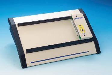

The Base Unit can be loaded with laboratory cards which have been carefully designed to suit each particular area of study.
The Lab Cards are placed in slots and are automatically powered via a D-sub connector.
General Data:
Supply voltage: 220 - 240 V 50-60Hz 1-phase.
The unit has 6 outputs with following data:
Outputs 1-3: DC 12V / 3A with LED indication and fuse.
Outputs 4-6: AC 24V / 3A with LED indication and fuse.
Dimension: 370 x 180 x 75 mm.
Weight: 4 kg
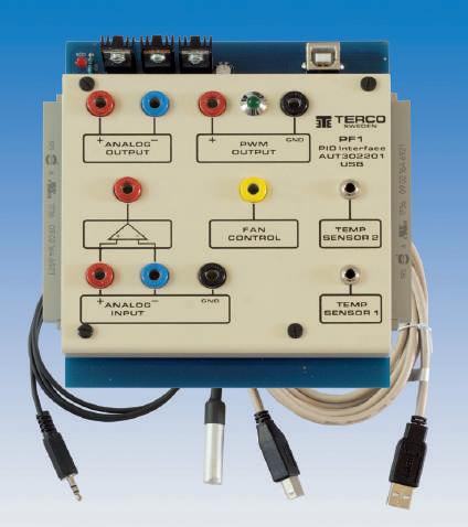
AUT302201 PID Interface PF1
PF1 is to be mounted on the Base Unit 2000 and connected to a PC using the software PRG 302200 (See page 5). The PF1 has one analogue input, one analogue output, current or voltage loop, one PWM output, one output for control of the fan and two inputs for temperature sensors.
General data:
Input Signal: 0-20 mA
4-20 mA
0-1 V (diff.input)
Output Signal: 0-20 mA 4-20 mA 20-0 mA
Smart Temperature Transmitter
20-4 mA -300C - +1300C
PWM output: 1Hz
Dimension: 135 x 140 x 36 mm
Weight: 0.5 kg
AUT302202 Temperature Module PF2
PF2 is a Temperature Regulation system including a heating chamber (oven) of approx. 50W, a temperature sensor and a fan for cooling. It is connected to and regulated by the PID Interface PF1.
General Data:
Heating Chamber: 50 W
Dimension: 145 x 140 x 105 mm
Weight: 0.5 kg
AUT302203 Speed Regulation Module


PF3
PF3 consists of a 12V DC motor, which has a 12V DC generator as a load. The purpose is to regulate the speed of the motor. It is connected to the PID interface PF1.
Dimension: 150 x 140 x 60 mm
Weight: 1 kg
AUT302204 Signal Converter PF4 Including Band Cable
PF4 is an interface for adapting signals from the PC based PID- Future to the Tank Model. It is connected to PF1.
The Signal Converter is required to communicate between the PID Interface PF1 and the Car and Tank Models.
Dimension: 140 x 58 x 24 mm
Weight: 0.2 kg
AUT302103 Regulator module

The analogue controller, complete with contact module and band cable, is connected to base unit 2000. Setting of P, I and D is completed by trimming the potentiometer and setting of relays, rather than input data via a computer.

Dimensions: 240 x 140 x 30 mm
Weight: 0.3 kg
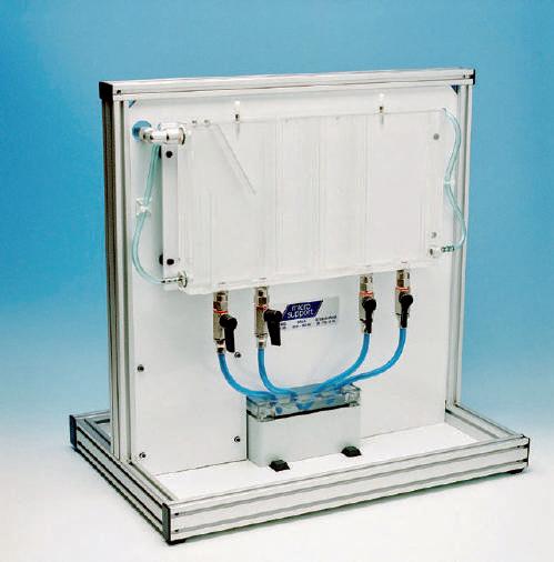
AUT302102 Tank Model
The Tank Model can be used to regulate level and flow. It is connected via a band cable to the signal converter PF4 which is connected to the regulator interface PF1. The model consists of a container (tank) having a capacity of 1 liter, where the level is measured at 2 places by means of a pressure gauge. The level tank can be divided into max three volumes to create different flow levels in the process. There are four taps for draining off the water to create different loads. The flow to the tank is measured by a sensor on a turbine wheel. The pump motor is driven via a rectifier which regulates the speed of the pump.
General data:
Supply Voltage: 24V DC
Current: 5A
Dimension: 550 x 350 x 510 mm
Weight: 11.7 kg
AUT302210 Sensor Set

The sensor kit consists of:
• 1 m thermocouple wire
• 1 PT 100 closed sensor
• 1 temperature sensor
The sensor kit is supplied with the required data sheets and is adapted for measuring courses, but can be used in other courses.
Dimensions: 250 x 90 x 65 mm
Weight: 0.4 kg
BOK302205 Control Techniques - Basic

Contents:
Control of the car model
Equipment installation
Temperature regulation
Speed regulation
Regulator models time constant
Measuring techniques
Examination of the tank model
Analogue regulator
Thermo element
Resistive temperature sensor
Light relay
Project work


