
7 minute read
Mecha-Kit System

from Terco Catalogue 2022
by terco-swe

AUT300200 Mecha-Kit
Terco Mecha-Kit is a modular system for education in pneumatic and control techniques, known today as Mechatronics.
Advertisement
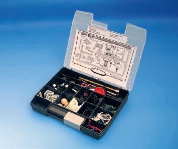
The Kit consists of an Aluminum base plate and a hard case, and a plastic box containing a number of different components within the field of Mechanics, Electronics, and Pneumatics.

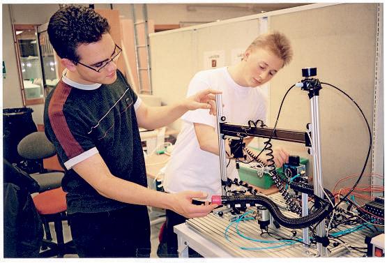
With the Kit the students can build a number of simple automatically controlled handling units where only the imagination of the students sets the limit.
All electrical wiring and pneumatic circuitry work is done by the students.
The combination of direct hands on training and almost unlimited possibilities, inspire the students and quickly increases their interest in this kind of engineering. Most of the handling units can be linked to a PLC unit for automated control.
The units can be linked together and form a network and simulate a flexible manufacturing cell.
Mecha-Kit components are contained in a hard shell hand box which is easy to carry and easy to stowe away
General Data:
Operating Voltage 24V DC +/- 10%
Working Pressure 5-7 bars
Dimension: 600 x 590 x 220 mm
Weight: 17.5 kg
An assembled portal robot, 2 axis.
List of components in Mecha-Kit system
Profile System
1 Base plate with carrier handle, 600 x 560 mm, no. 1
1 Assembly bracket, low angle and two mounting screws, no. 2
1 Assembly bracket, high angle and two mounting screws, no. 3
2 T-profile, long angle and two mounting screws, nos. 4 and 5
1 T-profile, smaller, no. 6
1 Frame profile, larger, length 506 mm, no. 7
1 Frame profile, larger, length 467 mm, no. 8
1 Frame profile, smaller, length 150 mm, no. 9
1 Frame profile, short, length 55 mm, with T-groove mounting, no. 10
1 Short tube for suction plug, no. 11
1 Long tube for suction plug, no. 12
6 T-groove mountings for profiles
12 Mounting nuts, round, with plastic
1 Mounting for sensors, no. 13
Pneumatic and Electrical Components


1 Air handling unit 1/4” conn. with shut-off valve, filter, pressure regulator and pressure gauge
1 Manifold lock, with connections
1 Pressure regulator with pressure gauge and non-return throttle valve
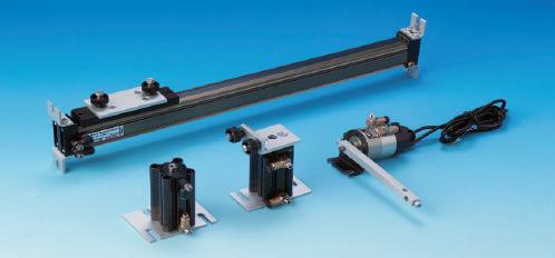
1 Double-acting cylinder, Ø 20 mm, stroke 40 mm, complete with mounting plate and mounting nuts
1 Double-acting cylinder, Ø 20 mm, stroke 50 mm, complete with mounting plate
1 Swivel device with 180° swivel, complete with mounting bracket, rotary arm and two PNP sensors
1 Shuttle cylinder Ø 16 mm, stroke 300 mm, complete with subplate and mounting brackets
8 Variable non-return throttle valves, mounted on all cylinder ports
1 Valve unit comprising six unistable valves, electrical control with spring return
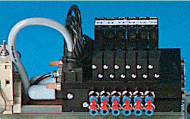
1 Manifold block, electrical with starter button
6 PNP sensors, 3-wire
1 Vacuum monitor sensor
1 Ejector, complete with vacuum gauge
1 Plastic ejector, complete with connections
1 Suction pad with nipple
1 Suction pad, bellows type
1 Main air supply valve
Other components included
1 Plastic storage box, 250 x 205 x 40 mm
2 Mountings for ball conveyor
1 Ball conveyor, 600 mm
1 Plastic cup, red Ø 35 x 15 mm
3 Pucks Ø 50 mm, height 30 mm, white, black and metallic
1 Square, 50 mm side, height 30 mm.
4 Wooden balls Ø 22 mm
1 Ball socket
5 Straight connection leads for sensors, 1 m
3 Angle connection leads for sensors, 1 m
4 Sensor mountings with double-acting cylinders
3 Sensor mountings for shuttle cylinder (painted red)
1 Dismantling fork
1 Plastic tube 4 mm, 5 m
1 Spiral hose, one of each single, double, triple 4 mm
1 Plastic tube clipper
2 Plastic mountings for cable and sensors

1 Screwdriver
1 8mm spanner
3 Hexagon (Allen) keys, 2 mm, 3 mm, 4 mm
2 T-coupling Ø 4 mm
10 Plugs Ø 4 mm
1 Tote box for profile systems and components, with inlay and mounting for tube and spiral hose, 530 x 385 x 120 mm
ELE102000 Base Unit 2000
The starting point of this laboratory system is Base Unit 2000, a control panel and PCB-holder.

The Base Unit can be loaded with laboratory cards which have been carefully designed to suit each particular area of study.
The Lab Cards are placed in slots and are automatically powered via a D-sub connector.
General Data:
Supply voltage 220-240V 50-60Hz 1-phase.
The unit has 6 outputs with following data:
Outputs 1-3: DC 12V / 3A with LED indication and fuse. Outputs 4-6: AC 24V / 3A with LED indication and fuse.
Dimension: 370 x 180 x 75 mm.
Weight: 4 kg
AUT302000 PLC Module

The PLC - Module has to be connected to the Base Unit 2000. To program a PLC a PC is connected to a programming port via a cable. Alternatively a PC software may be used for programming.
The PLC-module contains a PLC-system with sockets to connect any chosen module card. For the sockets there are several switches to simulate faults at the different inand outputs.
General data
Mitsubishi Melsec FX3s DS PLC ( 24 V )
8 inputs and 6 outputs
Input and output of the PLC is connected to a 20 pin socket.
Dimensions: 240 x 140 x 55 mm
Weight: 0.5 kg
AUT302001 Simulation Module
The output signal levels can be altered using the Simulation Module that is plugged into the sockets of the PLC Module.
Shows output status with 6 LED´s and has input signals simulated by 8 on/off switches.

Dimension: 100 x 140 x 40 mm
Weight: 0.1 kg
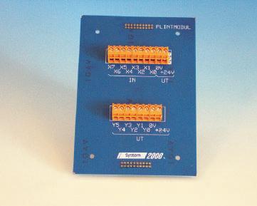
AUT302004 Terminal Block Module
The Terminal Block Module is to be connected to the PLC-Module. The PLC-Module together with the the Terminal Block Module will be used for connections to the Ball Selection Module. The connections will be made with one wire to each output and input. In this case there will be 8 inputs and 6 outputs for control of the valves (for the cylinders), and sensors on the Ball Selection Module.
Conection between PLC and Lab Equipment
Dimension: 100 x 140 x 40 mm
Weight: 0.1 kg
AUT302002 Traffic Lights Module

The Traffic Lights Module is to be connected to the PLC Module.The Module simulates a traffic crossing for cars and pedestrians at a pedestrian crossing.
When experimenting with the Traffic Module, the student has the task of creating a PLC program to control the traffic lights.
There are red and green lights for the pedestrian crossing, and red, yellow and green for the vehicle traffic.
Dimension: 100 x 140 x 40 mm
Weight: 0.1 kg
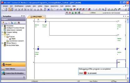
AUT310710 Programming Software for PC
Programming software IQ Works for programming of PLC from PC including USB cable.
BOK300201 Text Book
Contents:
• What is Automation
• Actuators
• Valves
• Grippers
• Sensors
• Control systems

• Automation units
• Hints on commissioning and fault finding
• For practical training we have a laboratory exercise book.
BOK300200 Laboratory Exercise Book
Contents:
• Equipment explanation
• Cylinder power, setting force
• Deceleration, setting speed and deceleration
• Vacuum, use vacuum to grip
• Measuring fixture
• Pick and Place robot with short movements

• Pick and Place with rotation
• Linear movements
• Assembly station
• Hoist
• Pick and Place with shuttle, rotation device and cylinder
• Self-constructed Pick and Place


Two steps to teach modern vehicle electronics
TERCO Automotive Electronics has been divided into two educational stages: Automotive Step One which covers basic electricity and electronics and is a training package for the basics of automotive electronics.
Training equipment makes it possible to create a simple learning situation, minimize the connection and measurement errors, and above all the time to complete all phases of the course in the time available.
Automotive Step One
The training package is built around power a base unit, which contains the power supply and is holder of the power adapter and the various lab-cards.
Automotive Step Two shows how different things happen in a vehicle by sending signals on two wires. To demonstrate this, there are two circuit boards that represent the dashboard and a car module for illumination and door closing. PCB dashboard each model are respectively coupled to the CPU.
Between CPUs go signals on the two wires (CAN-BUS) for various indications and actions.
A “fault finding unit” placed between CPUs makes it possible to learn the errors that may occur.
FOR102000 Base Unit
The power unit contains a power supply and is holder of the power adapter and the various lab cards. Power base unit can also be used to all other lab cards in the System 2000 series.

Mains: 230V / 50Hz
Power Supply: 12V AC and DC, 8A
Dimension: 376x215x355 mm
Weight: 7.8 kg
FOR102001 ES1 Series Connection

By connecting a number of lamps in series in different ways the student can study the current and the voltage across each lamp.
Dimension: 240x50x140 mm
Weight: 0.3 kg
FOR102002 ES2 Parallel connection

By connecting a number of lamps in parallel in different ways the student can study the voltage and the current through each lamp.
Dimension: 240x50x140 mm
Weight: 0.3 kg
FOR102003 Heating chair
The student studies the current and voltage and the heat that arises. If a heating coil fails, the effect can be so great that a fire occurs. Current and voltage generate heat, sometimes with fire as a result. The exercises show what happens when transferring to the ground, short-circuiting and interrupting and treating the concept of power.
Dimension: 240x95x140 mm
Weight: 0.3 kg
FOR102004 ES4 Inductive Sensor. This card consists of an inductive sensor and a toothed wheel driven by an electric motor with two different speeds. Speed by switched using a switch. The inductive sensor is an important component in automotive electronics. It is appropriate to use both multimeter and oscilloscope.

Dimension: 240x80x140 mm
Weight: 0.3 kg
FOR102005 ES5 Hall Sensor.
An electric motor drives a rotor gap where a Hall sensor is placed. Two different speeds can be obtained by means of switches. Measurement done with the oscilloscope.

Dimension: 240x65x140 mm
Weight: 0.3 kg
FOR102006 ES6 Relay
The card contains a closing relay, the opening relay and 3 lamp holder. The lamp holder can use bulbs with different power.

Dimension: 260x55x140 mm
Weight: 0.3 kg
FOR102007 ES7 Electronic Power Control PWM

With electronic control effect can continually be adjusted with pulse width modulation. The losses will be minimal compared to control using resistor.

The technique of varying the pulse width of the pulsating DC voltage is used in many applications in vehicles.
Dimension: 240x36x140 mm
Weight: 0.3 kg
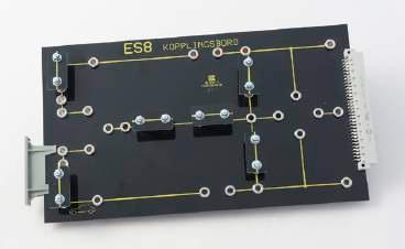
FOR102008 ES8 Terminal Board

The card consists of a number of 4mm connection socket where you can connect components contained in kit component (plug-in components). There are a number of exercises using components which are common in vehicles.
Dimension: 260x18x140 mm
Weight: 0.3 kg
FOR102010 ES10 Demister
The card is an example of an electrically heated car window. Because the card has a smaller area than a normal car window it uses a lower voltage at the trials so that no overheating occurs.
Dimension: 260x42x140 mm
Weight: 0.2 kg
FOR102009 ES9 Additional Power Supply
12V AC and DC
Dimension: 130x18x140 mm
Weight: 0.1 kg
FOR102011 ES11 Component Kit
Component kit for coupling table ES8. The Component kit contains various electrical and electronics components:


• Resistors
• PTC and NTC resistors
• Capacitors
• Diodes
• Transistors
• Switches
• Coil with an iron core
• Lamps
• Wires
Dimension: 335x50x255 mm
Weight: 1.3 kg


