14 minute read
Motor Control System

from Terco Catalogue 2022
by terco-swe

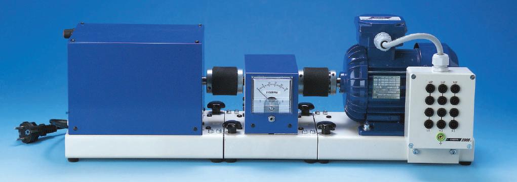
A Motor Control package including the DC-motor and the AC-motor, controlled in different, modern ways. The AC- and the DC-drives are the main subjects to be studied in this package. Other types of drives can be studied in connection with motor control in industry.
The package also covers combinations with control techniques and electricity. The experiments are performed with AC- and DC-motors, which can easily be mechanically connected together. They can be loaded steplessly, with a magnetic powder brake. Experiments are made with different control equipment used to drive and to control motors. Examples of control equipment are contactors, frequency converters, DC-drives and PLC. This equipment may be fixed in different units or on a module card to be connected to the Base Unit 2000.
Advertisement
Connection is done on terminals in an apparatus housing covering contactors, frequency converters, DCdrives, PLC and other applications. The experiment book is mainly built on connections with laboratory leads of safety design with 4 mm terminals.
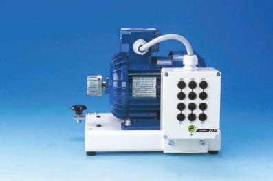
ELK102240 Squirrel-cage 3-phase asynchronous motor
The motor is mounted on a steel base to be connected to a magnetic powder brake or to other electrical machines with a quick shaft coupling.
The AC-motor can be switched between Y and D. The supply to the main current circuit of the AC-motor leads through a 3-phase terminal connected to a 3-phase net.
The AC-motor can also be supplied via a frequency converter.
General data
Voltage: 230/400 V 3-ph, 50 - 60 Hz
Current: 1.55 / 0.9 A
Power: 0.25 kW, 1380 rpm, at 50 Hz
Power factor 0.68
Dimensions: 280 x 220 x 225 mm
Weight: 8 kg
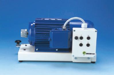
ELK102250 DC-Motor
The motor is mounted on a steel base to be connected to a magnetic powder brake or to other electrical machines with a quick shaft coupling. The DC-Motor has open shunt winding to make it possible to connect it as shunt or separate excitated DC - Motor
General data
Shunt wound DC-motor.
Armature voltage: 160 V
Field voltage: 190 V
Armature current: 2.1 A
Power: 0.25 kW
Speed: 1500 rpm.
Dimensions: 380 x 220 x 250 mm
Weight: 13 kg
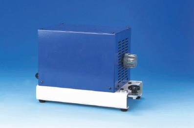
ELK102242 Magnetic Powder Brake
To be used together with the AC-motor ELK102240 and DC-motor ELK102250.
Brake 0-10 Nm adjustable with a 10-turn potentiometer.
General data
Power supply: 230 V, 50 - 60 Hz.
Effect consumption max: 25 W.
Dimensions: 300 x 160 x 200 mm
Weight: 7 kg
ELK102244 Tachometer
To measure the rpm of a motor, the tachometer is connected to the motor shaft. The tachometer shows an analogue signal output in form of voltage which is in proportion to the rpm of the rotating shaft. It works like a DC generator. The measuring instrument has a scale of 0-2500 rpm.
Voltage output DC 0-20 V, may be used for voltage feedback to the DC- or AC - Drive.
General data
Output: 20 V DC at 2500 rpm
Dimensions: 210 x 160 x 150 mm
Weight: 3 kg
ELK102246 AC - Drive
The AC-Drive is suitable to control the speed of an AC motor. It is perfect in many industrial applications e.g. pumps, fans, drilling machines etc. The AC - Drive can be set with 100 different parameters e.g. acceleration & retardation times, current limit, over load, alarm, speed ranges. It has also a built -in PID regulator. Here we focus the use of soft start and soft stop, rpm control and study the electronic overload protection.


General data
Max motor power: 0.4 kW
Input voltage: 230 V 1-ph, 50 - 60 Hz
Output voltage: 0-230 V 3-ph
Current. 2.5 A
Output frequency: 0.5-120 Hz
Dimensions: 230 x 250 x 245 mm
Weight: 2.6 kg
ELK102248 DC - Drive
The DC-Drive is used to run the DC motor. Here the parameters are set, as rpm, current limits, acceleration, ramps and others.
General data
Current max: 12 A
Armature voltage: 0-180 V DC.
Field voltage: 200 V DC.
Field current max: 1 A
Acceleration period: 0.2-5 s.
Feedback with armature current or tacho.
Supply voltage: 230 V 1-ph, 50 - 60 Hz.
Dimensions: 230 x 250 x 245 mm
Weight: 2.6 kg
ELE102232 Three Phase Terminal
The AC-motor can be connected to a 3-phase net by a 3-phase terminal with a 5-pole 16 A electrical output as to standard CEE17. Inside the terminal panel there is a control device for the 3-phases and the neutral line. The different phases are fused and in the terminal box is an insulation transformer (1:1) as well.
The terminal panel is equipped for current- and voltage measuring on all phases and includes a phase sequence display where LED indicate the phase sequence. The connection from the 3-phase terminal panel to the AC-motor is done with lab leads, directly or via the Contactor Unit. Only 4 mm safety lab sockets are used.

General data
Supply voltage: Prim. 5-pol. 400/230 V 3-ph, 50 - 60 Hz, 2,5A Sec. 5-pol 400/230 V 3-ph, 50-60 Hz, 2,5 A
Dimensions: 510 x 190 x 320 mm
Weight: 8.3 kg
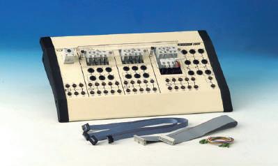
ELE102000 Base Unit 2000
Base Unit 2000 is the base for the Lab System 2000. It is a Control Box comprising power supply, circuit box and PCB-holder. Into the Base Unit laboratory cards can be fitted. The cards have been carefully designed to suit each particular area of study. The lab cards when fitted are automatically powered via D-sub connector.
Base Unit 2000 is a common unit to be connected to different equipment. The Base Unit is connected to 230 V AC and feeds voltage to the connected modules which are inserted between a pair of short guides and there connected to a 64-pole housing.


General data
Supply voltage 230 V , 50 - 60 Hz 1-phase
The unit has 6 outputs with following data:
Output 1 - 3: DC 12V / 3 A with LED indication and fuses
Output 4 - 6: AC 12V / 3 A with LED indication and fuses
Dimensions: 370 x 180 x 75 mm
Weight: 4 kg
AUT302011 Control Module
The AC-motor is started and stopped by push button controlled electrical switches, located in the Control Module. They are specified with indication as normally closed (NC) or normally open (NO) contacts and there are two of each. In the Control Module you also find a number of indicating lamps. Two of them are red and two of them are green. To control the motor 24 V AC is used which is supplied from the Base Unit 2000, where the Control Module is to be connected. The Base Unit may be loaded up to 50 VA. The Control Module holds also 24 V DC for other experiments.
General data
The Control Module consists of:
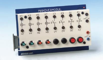
• 2 push buttons, NC • 2 lamps
• 2 push buttons, NO • Output 24 V DC and 24 V AC The Control Module has to be connected to the Base Unit 2000.
Dimensions: 240 x 140 x 55 mm
Weight: 0.7 kg
AUT302012 Contactor Unit
The Contactor Unit is used to control the motor. It connects the 3-phases from the 3-phase terminal to the AC-motor.
3 mini-contactors are placed in the Contactor Unit. If any of the contactors is in use, this is indicated by a LED. Two of the contactors have an auxiliary contact block and the third one has both, an auxiliary contact block and a thermal overload protection which is released at too high current output at any of the three phases meant for the motor drive. The time relay can be connected to one of the contactors.The auxiliary contact blocks are used together with the contacts in the Control Module when controlling the AC-motor. Mains supply terminals of safety design.
General data
Operating voltage: 24 V AC
Main voltage: 400 V 3-ph, 50 - 60 Hz
Max current: 10 A
Dimensions: 390 x 260 x 130 mm
Weight: 3.3 kg
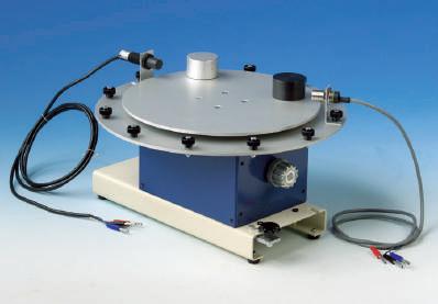
ELK102252 Rotary Index Table
The Rotary index table is to be connected to a motor via a coupling. The rotary index table includes a worm gear where the outgoing vertical shaft drives a fixture plate. The worm gear reduces the speed 30:1. The rotary index table shall be driven by an electrical motor by a ball bearing suspended shaft. The fixture plate with holders and sensors to recognize different materials. Suitable to learn about different controls with frequency converters or current rectifiers and PLC.
General data
Dimensions: 400 x 380 x 190 mm
Weight: 7.4 kg
PLC - System
A PLC is a small Mini -Computer for industrial use comprising all necessary logic functions gathered in one housing. The input to our PLC is done from, for example, different sensors or electrical contacts. The output of the signals is done via contactors, pneumatic valves etc.
AUT302000 PLC Module

The PLC - Module has to be connected to the Base Unit 2000. To program a PLC a PC is connected to a programming port via a cable alternatively a PC software may be used for programming.
The PLC-module contains a PLC-system with sockets to connect any chosen module card. For the sockets there are several switches to simulate faults at the different in- and outputs.
General data
Mitsubishi Melsec FX0-14 MR PLC ( 24 V )
8 inputs and 6 outputs
Input and output of the PLC is connected to a 20 pin socket
Dimensions: 240 x 140 x 55 mm
Weight: 0.5 kg
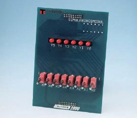
AUT302001 Simulation Module
The signal levels on the inputs can be altered through a simulation module, plugged into the sockets of the PLC module.
General data
Shows input status with 6 LED and has out-going signals simulated by 8 on/off switches.

Dimensions: 100 x 140 x 40 mm
Weight: 0.1 kg
AUT302008 Socket Adapter
To connect the PLC module to an control object, a 4 mm socket adapter is used. It is plugged onto the sockets of the PLC module and thus all in- and outputs of the PLC-system are connected to the 4 mm socket adapter. Thereupon it is easy to connect the PLC system to another control object with 4 mm lab leads.
The socket adapter has also four electrical switches to be able to give in-signals to the PLC-system. The electrical switches can be turned to NC or NO.
General data
Dimensions: 100 x 140 x 40 mm
Weight: 0.1 kg
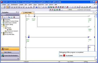
AUT310712 Programming Software for PC
Programming software GX Works2 for programming of PLC from PC including USB cable.
BOK103615 Experiments Book & Motor Control

Terco reserves the right to make changes in the design and modifications or improvements of the products at any time without incurring any obligations
DC-Drives
MV4207-1 DC-Motor Drive
Single-phase 4-Quadrant Rectifier, Three-Phase supply Covers the latest development in DC-motor operation with analogue control. The equipment is designed to work according to different industrial environments. The drive has signal in- and outputs for connections to slave and/or master drives.
To cover a wider range of machines regarding voltage and speed the primary supply is taken from a standard 3-phase outlet which will supply the inverter bridges by 2-phase 400 V.

The design will enhance the possibilities of learning the theory and practice of understanding the operation of 4Q-drives for both single drives and the basic understanding of three bridges and their commutation.
The 4-Q-DC-Drive can be used in the conception of speed/torque control versus electro-machine theory. When braking, the energy is transferred directly to the supplying network by operating in all four quadrants.
Technical Specification
Input voltage: 3-phase 3 x 400 V + N + PE, 50-60
Hz
Input max current: 16 A, rotor inductance is included
Output voltage: 0-250 V DC
Output current: 0 - 12 A (max 16 A)
Nom. output power: 2 kW
Design: Tutorial where the 4Q industrial/ professional aspects are enhanced
Control: Manually operated Digital / Analogue
Front control parameters: 12
Feedback: DC-tacho or armature voltage
Built-in unit for immediate: U+I+P signals, isolated, including MUX for oscilloscope. Built-in protections and contactor relays
Dimensions 520 x 450 x 280 mm
Weight 23 kg
Manuals
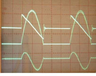
Consist of a theory section and an exercise section. The theory part explains for example general theory of the conditions for torque developed in an arbitrary machine, while the exercise section contains theory sections that are directly connected to the different experiments. The Manual consists of a complete binder together with an additional section , which will explain the UIP-unit (Voltage/Current/Power – unit) together with oscilloscope snap-shots showing different operation modes of the rectifier.
Standard Settings
12 Parameters are set manually:
Typically: Speed, Max Speed, Acc ram, Flux, Ret ramp, Ilim, Current/Speed proportional, Current demand in/ out, etc.
Floating switches and potentiometers are used to study step response and stability. The results of the dynamic response regarding voltage, current and immediate power can be studied fully isolated on a standard oscilloscope via the built in isolation amplifier and multiplexer.
Manuals
Consists of a large quantity of experiments where related theoretical analyzes and explanations are performed in each experiment. Experiments furtheron covers basic operation and autotuning as well as more advanced operation directly from the drive keypad (operator station) or from PC where signal analysis also are possible by means of the chart recorder and the oscilliscope function.
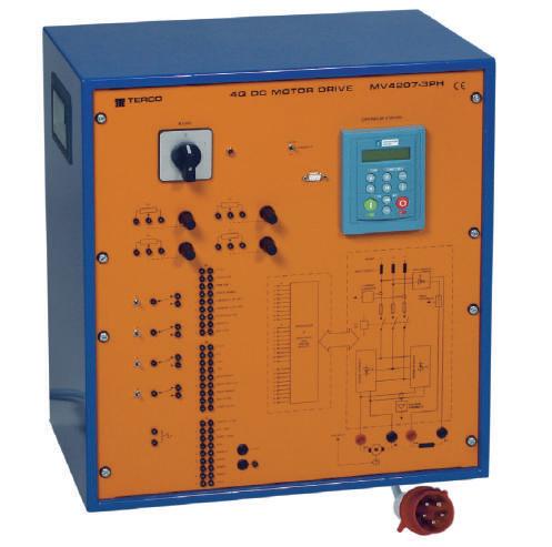
MV4207-3 DC-Motor Drive
Three-phase 4-Quadrant Rectifier, Three-Phase supply covers the latest development in DC-motor PC-controlled operation with 6 pulse 4Q rectifiers. The equipment is designed to work according to different function principles and it is possible to explain several different types of DC-drives depending on the purpose and industrial environment from traction to paper- and steel mills.
Output current/voltage can be chosen to optimize torque/angular speed or to optimize other parameters by using a PC and the enclosed software. When braking, the energy is transferred directly to the supplying network by operating in all four quadrants. The field rectifier can be programmed manually or from a PC for optimized field control.
The 4Q DC Drive can be used in the conception of speed/torque control versus electro-machine theory. The equipment is also suitable for experiments and tests in industrial applications.
Technical Specification
Input voltage: 3-phase 3 x 400 V + N + PE, 50-60 Hz
Input max current: 16 A
Output voltage: 0 - 400 V DC
Output current: 0 - 12 A (max 16 A)
Nominal output power: 2 kW (max 3 kW)
Design: Tutorial but with the PC-controller industrial / professional aspects enhanced.
Control modes: Manually by front components, Manually by Operator Station, PC by RS 232 +”DELite”” + software
Front controls: Manually Digital > 20, Analogue > 4
Configuration: by PC or Operator Station
Self-tuning: by PC or Operator Station
Built-in protections and contactor relays
Dimensions 520 x 450 x 280 mm
Weight: 25 kg
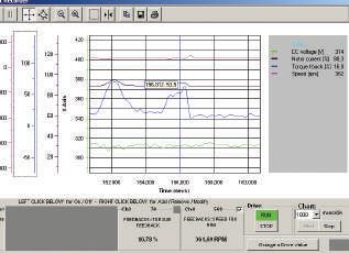
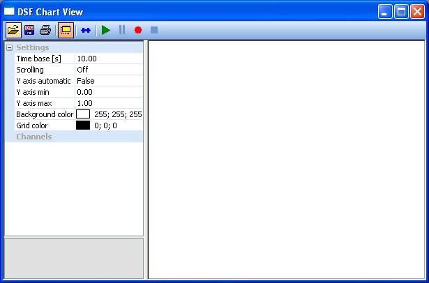
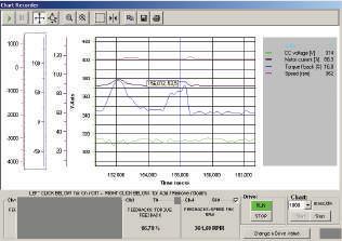
Built-in Instruments and Oscilloscope Functions
The enclosed software will make it possible to configure the internal connections and operating principles by using a standard PC. On the screen it is possible to monitor 3 analogue instruments and edit a number of signals/parameters in parallel, which can be saved and printed. The number of parameters/tags possible to study exceeds 200.
Standard Settings and Advanced Settings
Most parameters are set by default but settings can also be done manually from the front controls.

Typically:
Speed, Max Speed, Acc ram, Flux, Ret ramp, Ilim etc. Advanced settings, >200 parameters/tags, are performed by Operator Station on the unit, PC nearby the unit, connected to COM1 (COM2).
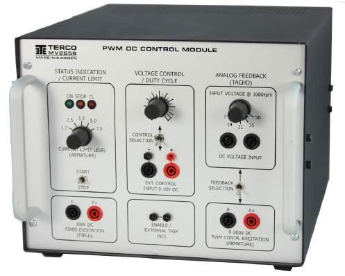
MV2658 PWM DC Control Module
MV2658 is an indispensable equipment in the electrical machines laboratory as it can be used in several different types of applications.
It can be used as a DC-Machine Drive in the range up to 1.2kW, a Generator Field Controller (VAr controller), or a Machine Brake Controller suitable with Terco equipment in the range up to 3.3kW
Technical Specifications
• PWM (16kHz) Based Excitation Voltage 0-260VDC.
• Selectable Current Limit Levels (front panel switch): 1.7ADC, 2.5ADC, 3.5ADC, 5.0ADC, 7.5ADC.
• Fixed Excitation Output 200VDC (for DC Drive application).
• PWM Controlled Excitation on the front panel control (0-100% Duty Cycle) or from the control input (fully isolated, 0-10VDC = 0-100% Duty Cycle).
The control input can be used for instance in PC based control together with Terco DAQ software. (Optional analog output interface unit necessary).
• Control Methods selectable between PWM Controlled Excitation Voltage Feedback and External Analog Voltage Feedback.
• Power Supply 220-240VAC, 50/60Hz
• Dimensions: 255 x 195 x 330mm
• Weight: 8kg
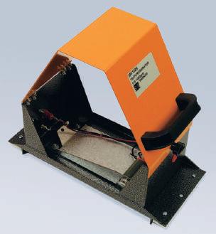
MV1024 Tachogenerator
The generator is mounted inside a protective guard. The cover is hinged and can be fixed by a locking screw.
General Data
DC Generator 14 V at 1000 rpm (with trim potentiometer)
Dimensions 300 x 260 x 130 mm
Weight 2 kg
Please note : The protective guard can be fitted between the machines to cover the rotating couplings, thus minimising the risk of accidents from rotating machinery.
MV1055 Spacer Shaft
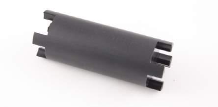
To be used as an shaft extension between MV1054 torque/speed meter and either the test machine or the braking/driving machine to give space for the MV1024 tachometer generator when doing closed-loop experiments with DC-drives.
MV1055 is also suitable between the MV1010 flywheel and the MV1054 torque/speed meter.
AC-Drives
MV4206-1 AC-Motor Drive
Semi 4Q frequency converter with MOS FET technique and a fixed intermediate DC-link.It covers the latest development in AC-motor operation with frequency converters. The equipment is designed to work according to different function principles and it is possible to explain several different types of frequency converters existing today.
4-Q-Drive: The Frequency Converter can be used in the conception of speed/torque control and electro-machine theory. The equipment is also suitable for experiments and tests in industries i.e. far beyond the area that the experiments show.
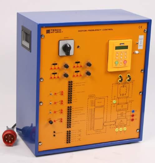
When braking, the energy is transferred by the DC-link and a brake chopper to a built-in load resistor. There is also an additional adjustable DC-injection brake.
Technical Specification
Input voltage: 3-phase 3 x 400 V + N + PE, 50-60 Hz
Input current: 16 A max
Output Power: 1.5 kW
Output voltage: 3 x 230 V
Max output current: 7 A
Max output frequency: 100 Hz
Choice of polygon: automatic
Breaking points: automatic
Internal switch frequency: 3 kHz max
Type of modulation: PWM sensorless vector
Intermediate DC-voltage: average value 300 V DC Inverter bridge: MOSFET
Control voltage: +/- 10V DC analog, 0-24V DC
Digital
Dimensions 520 x 450 x 280 mm
Weight 16 kg
Built-in Instruments Functions
Manuals consist of a theory section and exercise section together with a software description. The theory part explains for example general theory of the conditions for torque developed in an arbitrary machine, while the exercise section contains theory that are directly connected to the different experiments.
The instruction manual is enclosed as a complete binder together with a corresponding CD.
The enclosed software will make it possible to configure the internal connections and operating principles by using a standard PC. On the screen it is possible to monitor 3 analogue instruments and scroll a number of signals/ parameters in parallel, which can be saved and printed. The number of parameters/tags possible to study exceeds 200.
Standard Settings and Advanced Settings
Most parameters are set by default but settings can also be done manually from the front controls.
Typically: Speed, Max Speed, Acc ram, Flux, Ret ramp, I-lim etc.
Advanced settings: >200 parameters/tags, are performed by Operator Station on the unit, PC nearby the unit, connected via the comport.
General data
Max. Applicable Motor Output 1.5kW
Max. Applicable Motor Output 2.0hp
Rated Output Capacity 2.9kVA
Rated Output Current 7.5A
Maximum Output Voltage 3-ph prop. to input V.
Supply Input Current 15.7A (Fused 15A)
Supply Voltage/Frequency 1-phase 200-240VAC, 50/60Hz
Voltage Tolerance +-10% (180-264V)
Frequency Tolerance +-5% (46-63Hz)
MV2661 AC-Control
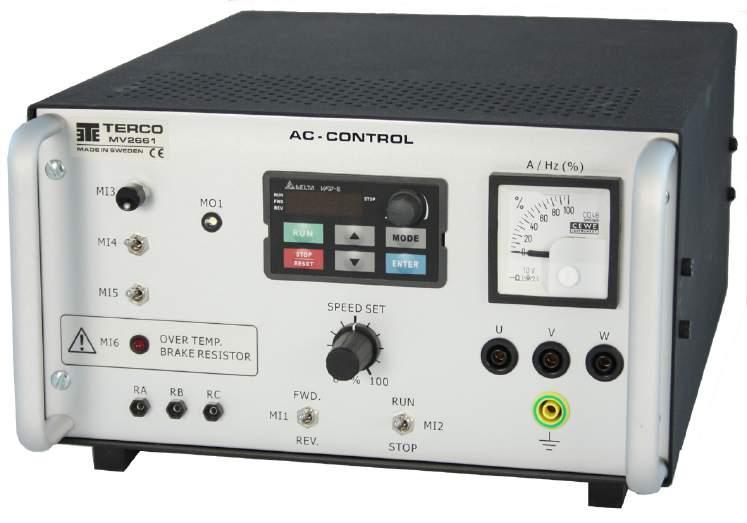
The MV2661 is an AC drive primarily designed for speed control of a 3-phase squirrel cage induction motor. Its purpose is to create a sinusoidal (or close to) 3-phase voltage that is connected to the stator of an AC-motor.
The AC-drive controls the pulse width and the frequency of the supplied voltage and can therefore keep the motor running at constant speed although the mechanical load applied at the rotor shaft varies. The AC drive includes an autotune-function which automatically identifies the electrical and mechanical parameters of the connected induction motor.
The drive is capable of operating machines up to 1.5kW. It controls the output voltage 3x(0-240)V and frequency 0.1-600Hz. The maximum output current is 7.5A and the input current 15.7A (fuse size 15A). It is mainly designed to operate together with TERCO MV-machines, which are sized 1.1 – 1.5kW.
The AC CONTROL MV2661 is furtheron equipped with an internal brake chopper and an internal brake resistor which makes it possible to study short ramp time braking coarses.
All essential signals are connected to the front to make it possible not only to run typical experiments verifying the theory but also to make it possible to run the drive out of more advanced industrial aspects.


