
3 minute read
Experiments Manual

from Terco Catalogue 2022
by terco-swe

The TERCO High Voltage Experiments Manual is a comprehensive manual which contains laboratory exercises with detailed text and figures how to connect the equipment and perform the experiment
List of Experiments
Advertisement
1. Generation and Measurement of Alternating Voltage
A. Capacitive Divider
B. Sphere gaps and standard tables
2. Generation and Measurement of Direct Voltages 1
A. Load characteristics of Rectifiers
B. Measurement of Ripple Factor
3. Generation and Measurement of Direct Voltages 2
A. Greinacher Voltage Doubler Circuit
B. Polarity effect and Insulating screens
4. Generation of impulse voltages
A. Lightning impulse voltage
B. Single stage impulse voltage circuits
C. Peak value measurements with sphere gaps
D. Break down probability
5. Measurement of impulse voltages
A. Multiplex circuit after Marx
B. Impulse voltage divider
C. Impulse voltage time curves
6. Power frequency and Impulse Voltage Tests on Power Transformer
A. Specifications for high voltage tests
B. Insulation coordination
C. Break down test for insulating oil (Test oil is not supplied by TERCO)
D. Transformer test with alternating voltage (Transformer is not supplied by TERCO)
E. Transformer test with lightning impulse voltage (Transformer is not supplied by TERCO)
7. Experiment on solids and Insulating Liquids
A. Breakdown strength of hard board plate (Test oil and hard board is not supplied by TERCO)
8. Experiment on Partial Discharge and Corona
A. Partial discharge at Needle electrode in air
B. Measurement in corona cage
9. Experiment on PD and Gliding Discharges
A. PD measurement in High Voltage Insulation
B. Measurement of Onset Voltages of Gliding Discharge
10. Breakdown of gases
A. Townsend mechanism
B. Streamer mechanism
Terco reserves the right to make changes in the design and modifications or improvements of the products at any time without incurring any obligations
Test Room
It is very important to house the HV9000 in a specially designed test enclosure. This must be built in accordance with the guidelines below, to a high standard and local safety regulations must be followed. For a single stage kit a floor space of 4 x 5 m is recommended, with a height of 2.5-3 m. Since voltages in excess of 1000 V are generated the safety regulations must be carefully followed. Fencing and grounding of the Test Room are very important.
Safety Equipment
The test area should be enclosed by a metal fence of at least 1.8 m in height and the mesh width not exceeding 50 mm. All doors leading into the test room must be equipped with door contacts, which lock when the door is closed.
All contacts shall be connected in series and fed to the appropriate sockets on the control desk. Red and green warning lamps must be installed on all doors leading into the test room. These lamps should be connected to the control desk.
Earthing (grounding)
Earthing is very important, absolutely necessary for a good test room for high voltage test equipment. Connection should be made with low inductance connections copper cables which connect all components of the high-voltage circuit that must be earthed to ONE earth terminal.
Earthing connections should be made without loops. A modern earthing technique is to cover the lab floor with Aluminum sheets ( 2mm thickness) which are bolted to the floor and connected internally with copper cables and to earth. 4 aluminum sheets 2 x 1 m are included in our Safety Cage (HV-CAGE 1).
Any screening surfaces, test objects and/or measuring instruments should be connected to the same earthing point which should be located inside the safety fence and have a lower earthing resistance than the surrounding building. In any case the earthing resistance should not exceed 2 ohm or local regulation values.

Installation and Training
The HV-Lab must be installed inside an appropriate protective shell. If installation and training is ordered from TERCO, the Safety Cage must also be included (compulsory).
Height of the Testroom :
1-Stage: min 3.0 m
2-Stage: min 3.5 m
3-Stage: min 4.0 m
Power Supply for HV9000 is 220/230V, 50/60Hz single phase.
Fuse 25A D characteristic.
Good earthing quality is recommended and should be carried out in accordance with local regulations
HV Cage Suggestion For Layout Of HV9000 Setup
Height of the Testroom: 1-Stage: min 3.0m;
HV-CAGE
1
Safety Cage for Stage 1, 2 and 3
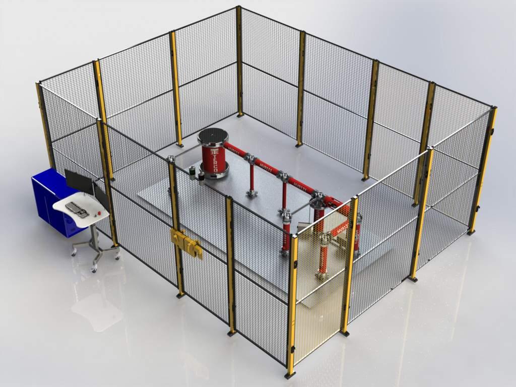
Floor area : 4 x 5 m2
Comprising :
Net-section 1.5 m x 2.2 m 8 pcs
Net-section 1.0 m x 2.2 m 5 pcs
Safety door with Master lock 1 pc
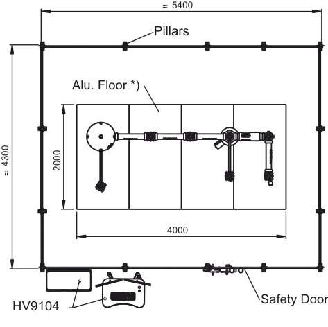
Pillar 50 x 70 mm, height 2.3 m 14 pcs
Green & Red Lamps
Aluminum floor (8sqm) comprising: 4 pcs aluminum sheets 2000 x 1000 x 2mm Set of Cables and Screws.
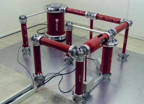
Different Experiment setups and Safety Net Installation
Different Experiment Setups And Safety Net Installation


Measurement of flashover
Measurement of flashover
Measurement of flashover voltage in vacuum and under pressure
Impulse Set-up
Measurement of flashover voltage in vacuum and under pressure

Impulse setup
Installation of Safety Fence
Demonstrating easy assembly
Demonstrating easy assembly
Installation of Safety Net
Technical Specification


