39 minute read
Chapter 4 SketchUp Basics


In order to use the methods in this book, you must understand the concepts, tools, and commands presented in this chapter. Any additional knowledge you have is a plus. However, don’t underestimate the usefulness of this chapter, even if you already consider yourself a SketchUp expert. It has plenty of tips, tricks, and helpful theories that will come up again later.
f i V e c ore c once PTS
Advertisement
Before you even open SketchUp, you need to understand the core concepts that make it unique. First, SketchUp is a surface modeler that is unlike most 3D modeling programs. Everything in SketchUp is composed of edges and surfaces, the basic building blocks used in SketchUp. A surface cannot exist without a closed loop of coplanar edges, and the simplest surface possible is a triangle (Figure 4.1).
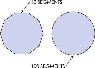
Second, because it is a surface modeler, there are no true, perfect vector curves, arcs, or circles in SketchUp. However, you can still represent circles and curves with a series of small edges (Figure 4.2).
Figure 4.1 All of the endpoints (corners) of the triangle are at the same blue elevation—in other words, the edges are all on the same plane (coplanar).
Third, SketchUp geometry has a tendency to stick together. This concept is known as the “stickiness of geometry” in SketchUp. Adjoining surfaces stick together and move with each other. Connected endpoints will move with each other and stretch their corresponding lines (Figure 4.3). Even though this can be frustrating at first, once you learn to control the stickiness, you will realize how much it speeds up the modeling process.
Figure 4.2 are represented by a series of smaller line segments. Increasing the number of segments makes a smoother circle, but can also decrease computer performance and lead to large file sizes.
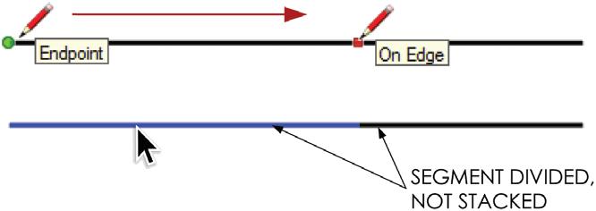
Fourth, geometry does not stack in SketchUp. Only one edge or surface can exist between the same series of points. Even when multiple edges are drawn on top of each other, the edges simply combine into one. When an edge is drawn that intersects or overlaps an existing edge, the existing edge will be broken into two pieces (Figure 4.4).
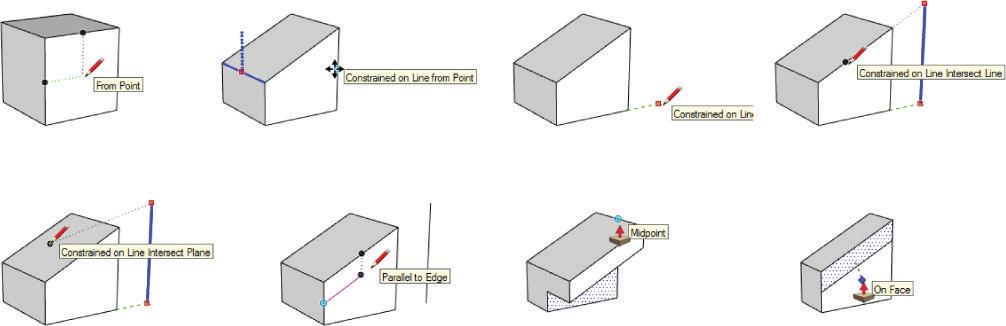
Lastly, the inference engine is the “brain” in SketchUp that is always working for you; it is what assumes meaningful relationships between points, edges, and surfaces. Although you can’t turn off the inference engine, you can control it through the power of suggestion. There are several inferences available in SketchUp, some are shown in Figure 4.5.
er A ging Ske T chU P
The five core concepts combine to make SketchUp a fast, fun, and unique 3D modeling program, but using it is not necessarily easy. By embracing and controlling these core concepts, you’ll be able to successfully leverage SketchUp into your workflow.
Selecting a Template
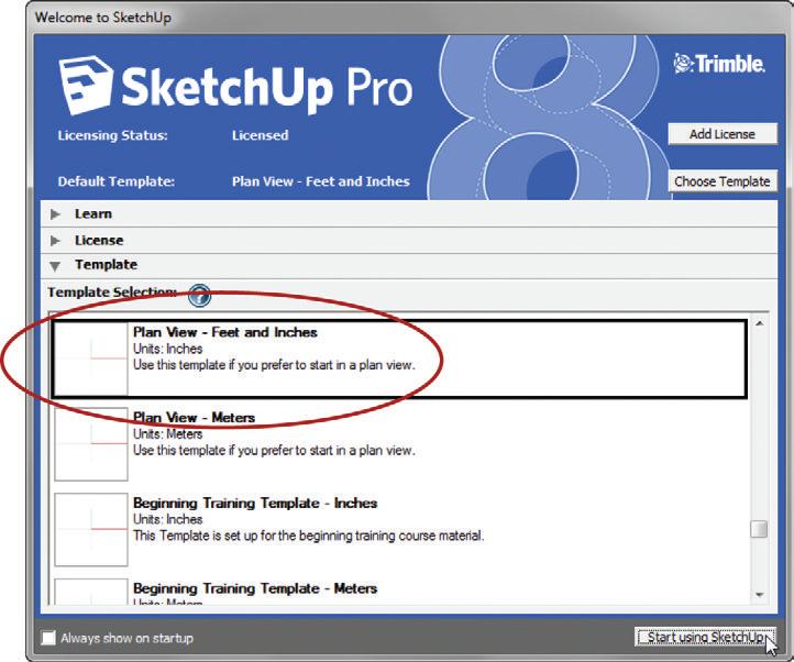
When you open the SketchUp application, the first window you’ll see is the Welcome to SketchUp window (Figure 4.6). You can also access it by clicking on the Help dropdown menu and choosing Welcome to SketchUp. From there, you can access learning resources, license information, and most important for now your default template. Within the Template tab, select the Plan View – Feet and Inches template and then click on Start Using SketchUp.
navigating the 3D environment
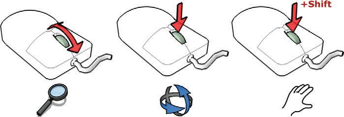
The best way to navigate in SketchUp is to use a three-button scroll-wheel mouse, even when you’re working on a laptop with a touch pad. Push down on the scroll-wheel button to orbit, hold down the Shift key with the scroll-wheel button to pan, and roll the scrollwheel to zoom (Figure 4.7).
You don’t need to use the Camera Tools icons on your screen because all of the Navigation tools are readily available at your fingertips (Figure 4.8). Actually, you’ll be better off if you completely ignore these icons. If you use them, you’ll have to search your screen outside of the work area. Every time you take your eyes off your design, you’ll focus on the wrong thing. Furthermore, you’ll give yourself a headache when you have to hunt around the screen for buttons.
Your cursor is the focal point of all navigation. Position it on the object you want to zoom in on, pan by, or orbit around so you will have more navigational control.
When you’re completing any task in SketchUp, always navigate to a view that is strategic for the task at hand. For instance, if you are trying to work on the elevation, don’t look at the model from a plan view. For any operation, you should always first determine the view that will make it easiest to perform the task. Also, be sure to utilize your large LCD monitor and really zoom in on the area you are working on.
Measurements
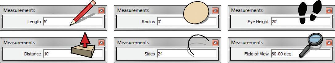
The Measurements dialog in SketchUp gives you complete control over any tool. Keep in mind that the Measurements dialog is always ready for your input. You never need to click in the Measurements dialog to enter a precise dimension or value; you just need to start typing.
By default, the Measurements toolbar is docked at the bottom-right corner of the SketchUp interface. You can reposition this toolbar by clicking on the View drop-down menu and choosing Toolbars c Measurements. Once the Measurements toolbar is floating, it can be repositioned or docked anywhere on the screen (Figure 4.9). The screen captures used in this chapter show a floating Measurements toolbar.
c re AT ing g eo M e T ry
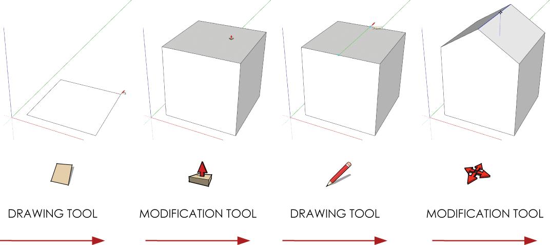
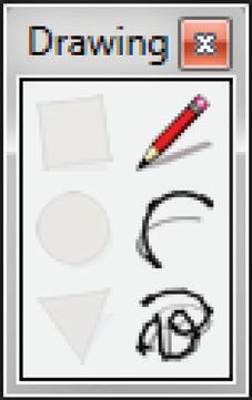
The most frequently used tools for creating geometry in SketchUp can be categorized into two groups: the Drawing tools and the Modification tools. To get started with any model, you must first create the geometry using the Drawing tools (the Line tool, Rectangle tool, Circle tool, Arc tool, Polygon tool, and Freehand tool). Once you’ve created simple 2D geometry, you can shape and change that geometry into a more complex form using the Modification tools (the Move tool, Push/Pull tool, Rotate tool, Follow Me tool, Scale tool, and Offset tool). Throughout the modeling process, you will likely go back and forth between these toolsets (Figure 4.10). Use the Drawing tools to create simple 2D geometry and make additional edges to break surfaces to set up operations for the Modification tools.
Drawing Tools
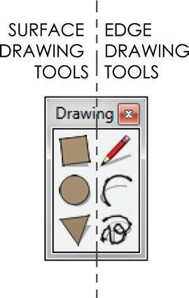
The Drawing tools can be further broken down into two groups: the Surface Drawing tools and the Edge Drawing tools. A Surface Drawing tool creates a closed loop of coplanar edges, including a surface, in a specified shape. An Edge Drawing tool creates straight and curved edges (no surface). These tools provide infinite combinations to complete additive and subtractive modeling operations (Figure 4.11).
Surface Drawing Tools
The Surface Drawing tools include the Rectangle, Circle, and Polygon tools. All of these tools create a closed loop of coplanar edges and a surface. It is best to start building a model using these tools (Figure 4.12).
Figure 4.12 Typically, you will begin a model using one of the Surface Drawing tools.
To use the Surface Drawing tools, you’ll need to click twice. Click once to start, move your cursor to suggest a direction, then click again to finish. Keep in mind that you can enter precise dimensions during the command or after the command, until another command is started. The same is true for most SketchUp tools.
TIP The best way to execute most SketchUp commands is to use the click-and-release method. The click-and-drag method will get you into trouble because it is easy to accidentally perform small unnoticeable commands with many of the tools. Typically, you should click once to start, move your cursor, click again to finish, and then enter a precise dimension.
Rectangle Tool
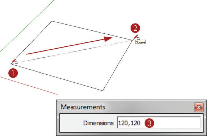
The Rectangle tool is a very effective tool for creating surfaces, and it certainly is one of the most frequently used tools in SketchUp. One of its great features is that the geometry it creates is always aligned with the axes. This means that you can create four edges and a surface, all squared up, with just two clicks (Figure 4.13).
1. Activate the Rectangle tool and click once to start.
2. Move your cursor to suggest a direction and click again to finish.
3. At this point, you can enter precise dimensions such as 120,120, then press Enter.
TIP you can override the alignment with axes by starting a rectangle on an off-axis edge. The rectangle tool will align new geometry with the edge on which it is started.
Circle and Polygon Tools
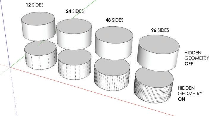
Because SketchUp is a surface modeler—meaning that the basic building blocks are edges and surfaces—there are no “true” circles in SketchUp. All circles are represented by a series of connected edges. The more sides a circle has, the smoother it looks (Figure 4.14). The default number of sides for a circle is 24 sides, and this number works for just about any circle you will need to create. Keep in mind that when you extrude a circle into a 3D form, every edge will become a surface with three additional edges. As a result, the more edges you have, the more 3D surfaces you create, and ultimately the slower your model will perform, which can be problematic.
Be aware of what you are modeling and how many sides you will need to achieve the quality you want. If you are creating a close-up rendering of a column, it would be appropriate to increase the number of sides before you create the circle base of the column. If you are rendering several columns for a building off in the distance, you could decrease the number of sides used to create the circle bases of the columns. There are times when a drastically lower number of sides is not noticeable. When you activate the Circle tool, you can change the default number of sides used to represent a circle (Figure 4.15).
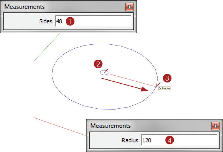
To create a circle, follow these steps:
1. Activate the Circle tool, then immediately type 48 and press Enter to change the default number of sides on a circle to 48 sides.
2. Click once to define the center point of the circle.
3. Move your cursor away from the center point on axis, click again to finish.
4. At this point, you can enter a precise radius such as 120, then press Enter.
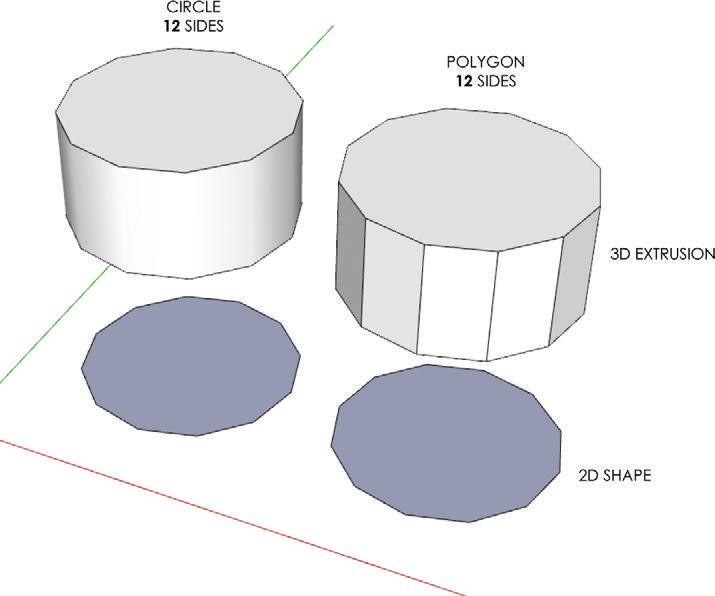
The Polygon tool works the same way the Circle tool does. The difference between the two is that a polygon’s edges are not softened when extruded (Figure 4.16).
Edge Drawing Tools
The Edge Drawing tools include the Line, Arc, and Freehand tools (Figure 4.17). These tools only create edges, not surfaces. You can use the Edge Drawing tools to make small additive and subtractive adjustments to existing surfaces. Although they aren’t the most efficient tools for creating surfaces from scratch, you can use them to actually draw the sides of a closed loop of coplanar edges.
Line Tool
The Line tool is the most basic Edge Drawing tool in SketchUp, and it is the tool with which most designers begin. Although it has many uses, surprisingly, using it is not the most effective way to create geometry. The Line tool is best used to make small adjustments and modifications.
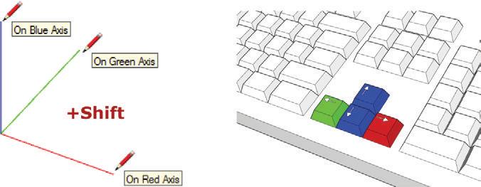
When you’re drawing in 3D with the Line tool, you can draw on axis by locking the Line tool on an axis.
To lock an axis, first find the axis and then hold down the Shift key to lock it. Finish the operation by clicking on a point to define the distance, and then release the Shift key. You can also lock an axis by tapping an arrow key while drawing a line. The Right arrow key locks the red axis, the Left arrow key locks the green axis, and the Up and Down arrow keys lock the blue axis.
Locking an axis eliminates two of the three dimensions, so all you need to do is define a distance along the specified locked axis (Figure 4.18). You can do this by using the inference engine to snap to a point, edge, or surface. Also, you can enter precise dimensions into the Measurements dialog.
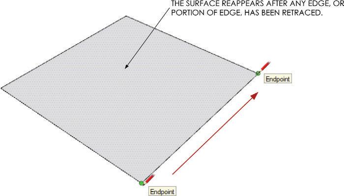
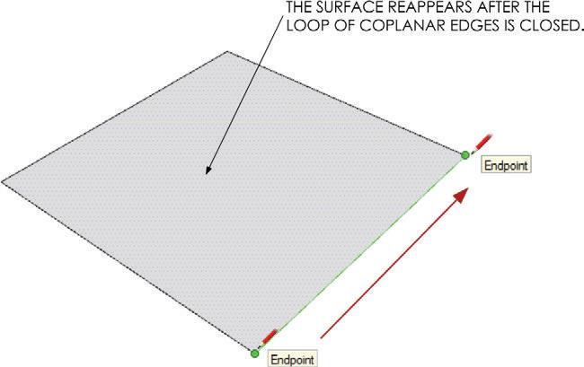
The Line tool can also be used to heal surfaces (Figure 4.19). Right-click on an edge of a surface and choose Erase. When you erase an edge, you break the closed loop of coplanar edges and, in turn, lose the surface. Redraw the line from point to point and you will have the edge and surface back.
Now, right-click on the surface and choose Erase to delete only the surface. Use the Line tool to retrace any edge around the closed loop of coplanar edges. The surface is now healed (Figure 4.20). Keep in mind that because geometry does not stack in SketchUp, there is only one edge remaining where you traced the edge.
Arc Tool
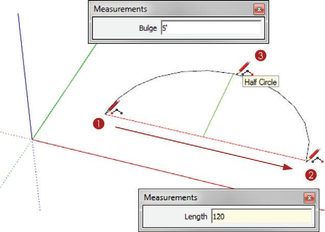
Use the Arc Tool to create precise curves. 1. Click once to define the starting point of the arc. 2. Click again to define the endpoint of the arc, or enter a precise dimension into the measurements dialog. 3. Click once more to define the bulge (Figure 4.21). Using the Measurements dialog, you can also enter a specific distance for the bulge.
need to make
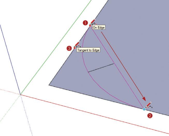
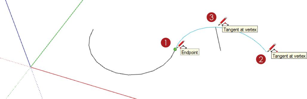
When you’re using the Arc tool to round the corners of a rectangle, look for the magenta Equidistant and Tangent to Edge inferences (Figure 4.22). When you’re continuing an arc, look for the cyan Tangent at Vertex inference to make a smooth transition between the two arcs (Figure 4.23).
Freehand Tool
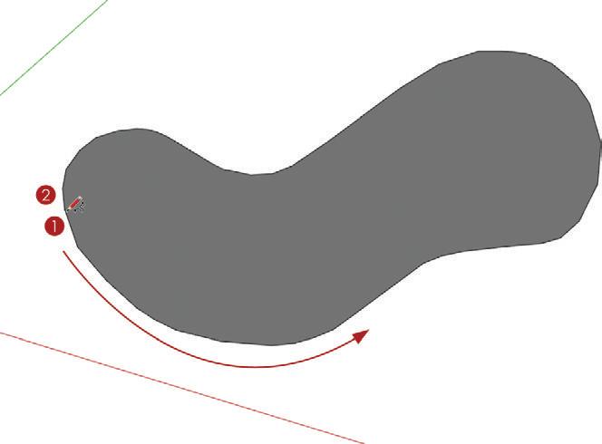
The Freehand tool is one of the few tools that require you to click and drag (Figure 4.24). You can use it to draw loose, sketchy lines. 1. Click and drag to draw a line. Release on the starting point to finish and create a surface.
TIP To learn how to draw more accurate loose curves, read about the Bézier curve plugin in chapter 8, “ruby Scripts.”
Modification Tools
Once you’ve created the geometry using the Drawing tools, you can change it using the Modification tools (Figure 4.25). The Modification tools can quickly transform 2D geometry into 3D objects and quickly create complex geometry by scaling, stretching, moving, and copying.

The Select Tool
The Select tool is included in the Principal tools, but it is critical for using the Modification tools. Of all the tools you need to master, this one is by far the most underestimated and the most important. You will use the Select tool before you use most of the other SketchUp tools. Typically, you will default back to the Select tool after issuing a command. All modification operations are complemented by the Select tool. It is best to preselect an entity before you use the Modification tools. Some of the Modification tools have a hot spot that auto-selects entities, but you will find that you can obtain complete control by first preselecting an entity with the Select tool. Click once on an edge or surface to select it. Double-click on a surface to select the surface as well as the bounding edges. Triple-click on a surface to select all of the connected geometry (Figure 4.26).
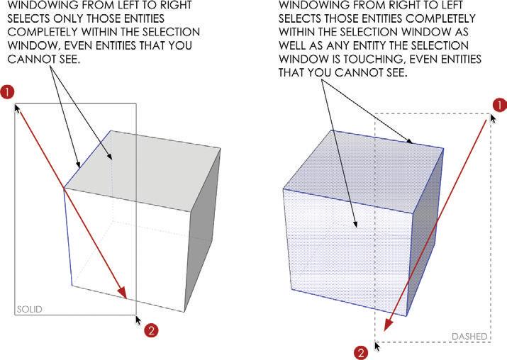
To perform a window selection, click and drag from left to right over the entities you want to select (Figure 4.27). Only the entities that are completely in the selection window will be selected. A window selection is represented by a solid selection window.
To perform a crossing selection, click and drag right to left over the entities you want to select. A crossing selection will select the entities that are completely within the selection window as well as any entity that the selection window touches. A crossing selection is represented by a dashed selection window.
Hold down the Ctrl key (Option on Mac) while you are using the Select tool to add entities to the selection. Hold down the Ctrl (Option on Mac) and Shift keys while you are using the Select tool to remove entities from the selection. Hold the Shift key while you are using the Select tool to inverse the selection. All of these modifier keys work with selection windows, too (Figure 4.28).
TIP Before starting any command it is best to clear all selections. you can deselect all of the entities in a model by clicking on the edit drop-down menu and choosing Deselect All, or by right-clicking on the model background.
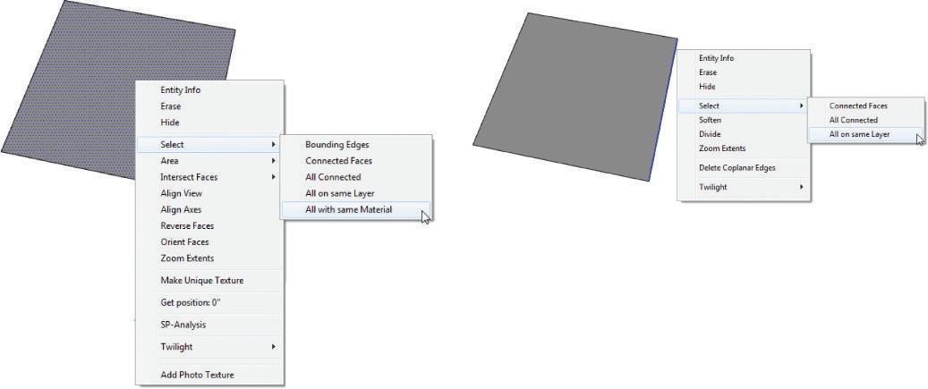
To see additional selection options, right-click on an edge or surface (Figure 4.29). From this menu, you can select Bounding Edges, Connected Faces, All Connected, All on Same Layer, or All with Same Material. These unique selection options can help you make complex selections faster.
If you find yourself tediously picking through a model, keep in mind that there is always a fast and easy way to make the selection you need. Use a combination of all of the selection techniques to select only what you need in the most effective manner. Approach the selection process just as you do the modeling process; the process can be additive or subtractive. Before starting the selection, ask yourself if it would be easier to select several entities and then deselect what you don’t need, or would it be better to add each piece individually. Perhaps using a combination of the two techniques would be the most effective. Every selection is different, so be sure to keep your approach flexible.
The Move Tool
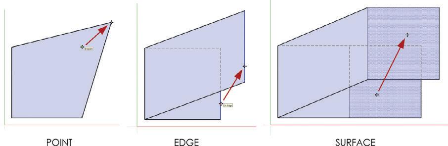
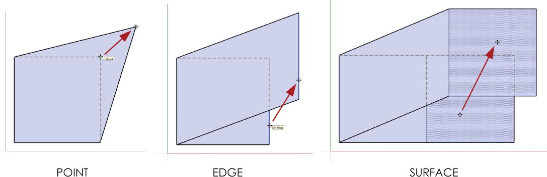
The Move tool’s efficiency relies heavily on the stickiness of the geometry. You can move points, edges, and surfaces using the Move tool. Moving each of these entities has a different effect on the entity, as well as the adjacent, connected entities (Figure 4.30). The Move tool’s hot spot is right in the middle of the icon. Place your cursor on an edge or a surface, and note that the Move tool will auto-select entities. Click once to pick an entity up, then click again to put it down.
TIP Beware! The Move tool is the number one destroyer of models. Be careful about what you are selecting and what is beyond your selection. you can select entities that are visibly blocked by other geometry, which makes it very easy to move entities accidentally and “blow out” the back of a model.
Precise Move
A precise move is executed by preselecting entities and then moving the selection from a specific spot on the selection to another specific spot in the model (Figure 4.31). A precise move can be started and ended on an edge, endpoint, midpoint, or surface, depending on the desired final location.
To make a precise move, follow these steps:
1. Using the Select tool, preselect the entity you want to move.
2. Activate the Move tool. Hover on the front-bottom corner of the cube until you see the Endpoint inference notification. Click once to pick up the cube.
3. Move your cursor, and the cube, to the front-bottom of the large cube. Hover on the corner until you see the Endpoint inference notification and click to place the cube.

TIP Don’t “eyeball it” when you can be precise. When performing a precise move, be sure to snap to other entities in your model.
Linear Copy and Array
The Move tool is also the “copy tool.” To toggle the Copy command on and off, tap the Ctrl key (Option on Mac). As you are moving any entity, tap the Ctrl key (Option on Mac) to leave a copy of it behind.
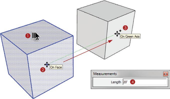
To make a copy, follow these steps (Figure 4.32):
1. Using the Select tool, preselect the entity that you want to copy.
2. Activate the Move tool and click once on the entity (you could start the copy from anywhere in the model).
3. Tap the Ctrl key (Option on Mac) to toggle on the Copy command while you move the cursor along an axis, then click again to finish.
4. At this point, enter a precise distance into the Measurements dialog, such as 20 f, then press Enter.
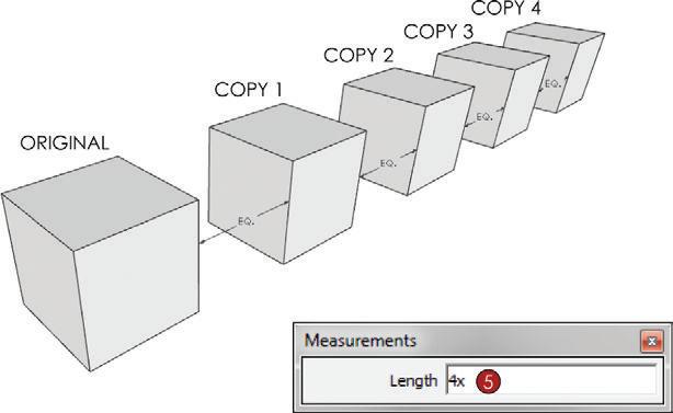
5. To create multiple copies at a specified distance, immediately after you complete the Move/Copy command, enter the number of copies you want to make—for example, type 4x , then press Enter. This will create four copies of the selection in addition to the original, just as a copy machine would (Figure 4.33).
Another way to array using the Move tool is to divide the distance between the copies (Figure 4.34). After you complete a copy, specify the number of divisions between the two copies within the Measurements dialog, as follows:
1. Using the Select tool, preselect the entity that you want to copy.
2. Activate the Move tool and click once on the entity (you could start the copy from anywhere in the model).
3. Tap the Ctrl key (Option on Mac) to toggle on the Copy command while you move the cursor along an axis, then click again to finish.
4. At this point, enter a precise distance into the Measurements dialog—for example, type 100', then press Enter.
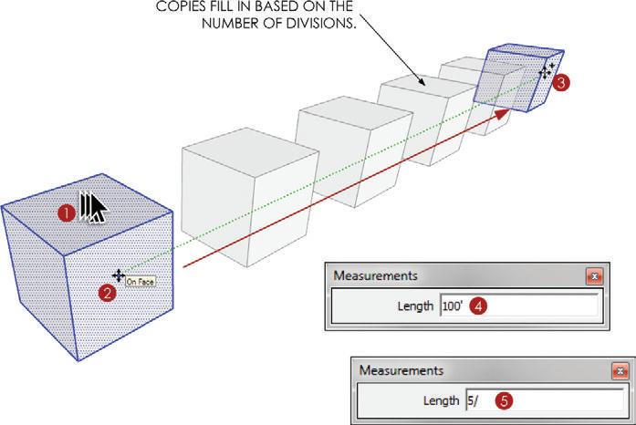
5. Immediately after entering the distance, enter the desired number of divisions between the two copies—for instance, type 5/, then press Enter.
You can continue to modify the copy and array until you start another command. Try entering different numbers of copies and different distances, and switch between using multiply and divide arrays. Once you click on another tool, you will lose the ability to modify the array (Figure 4.35). At that point, the new geometry will be just that, geometry. You will need to delete or reposition geometry to change the array.
Auto-fold
If a surface does not have the proper lines, or breaks, to fold the surface and allow the selection to move on all axes, it can stick to another surface. The Auto-fold command automatically draws all the lines needed to break a surface and allow the selected surface to move in any direction (Figure 4.36). While performing a move, tap the Alt key (command key on Mac) to toggle the Auto-fold command on.
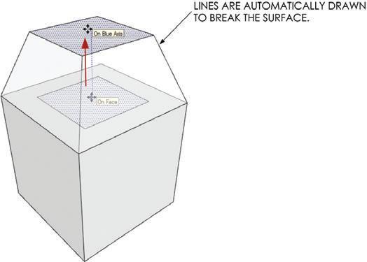
TIP Don’t use the Auto-fold command as a crutch. Sometimes it can appear to help make an entity move where you want it to, but it can actually create off-axis geometry that will be problematic later.
Push/Pull Tool
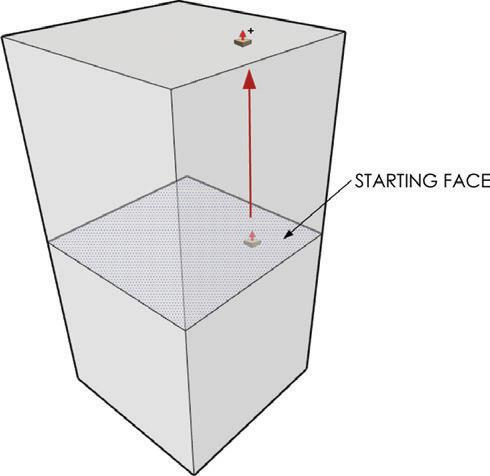
The Push/Pull tool is one of the fastest and easiest ways to generate large amounts of geometry. The Push/Pull tool extrudes 2D surfaces into 3D forms, perpendicular to the starting face. This means that geometry is typically on axis, or at least perfectly square with the starting surface. The Push/Pull tool affects only surfaces. Just follow these steps:
1. Position the Push/Pull tool on a surface; it will auto-select the surface. The hot spot of the Push/Pull tool is at the tip of the red arrow on the icon. Click on the surface to start the operation.
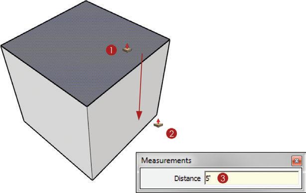
2. Move your cursor to push or pull the surface. The surface will extrude perpendicular to the starting surface (Figure 4.37). Click again to finish.
3. At this point, you can enter a precise dimension, type 5', then press Enter. Tap the Ctrl key (Option on Mac) before or during any Push/Pull operation to leave a copy of the starting face (Figure 4.38). This is a toggle, so tap the Ctrl key (Option on Mac) again and the starting face will disappear. In Chapter 17, “Site Analysis: Documenting an Existing Building,” you will see how valuable this function is for creating floorplans.
TIP The Push/Pull tool has a memory. once you have completed a Push/Pull operation, you can double-click on another surface to reproduce the last push/pull.
Follow Me Tool
The Follow Me tool generates massive amounts of complex geometry with very few clicks. This tool works by extruding a 2D profile along a path (Figure 4.39). A path can be a series of connected edges, or a surface which defines the path with its bounding edges. Follow these steps:
1. Using the Select tool, preselect the path, in this example a surface.
2. Activate the Follow Me tool.
3. Click on the profile to finish.
TIP The profile does not have to touch the path for the follow Me tool to work, although the operation and results make more sense and are easier to predict if it does touch the path.
Rotate Tool
The Rotate tool spins entities around a defined center point of rotation at a specified angle (Figure 4.40). To use it, follow these steps:
1. Using the Select tool, preselect the entity you want to rotate.
2. Activate the Rotate tool. Click and hold at the desired center point of rotation, and drag away to set the axis of rotation. Look for the inference line to turn red, green, or blue. Release once you have found the desired axis of rotation—for this example, rotate about the red axis.
TIP Use guides or encourage an inference to specify a meaningful center point of rotation.
3. Move your cursor around and notice that it is locked at the defined center point of rotation. Click to define the reference angle. The reference angle can be arbitrary for most rotations, unless you are trying to align one object with another.

4. Move your cursor and click again to define the degree of rotation away from the reference angle. You can click at a random angle, or
5. At this point let go of the mouse and enter a precise angle into the Measurements dialog—for example, type 90 , then press Enter. This will rotate the object 90 degrees off the reference angle around the defined center point of rotation.
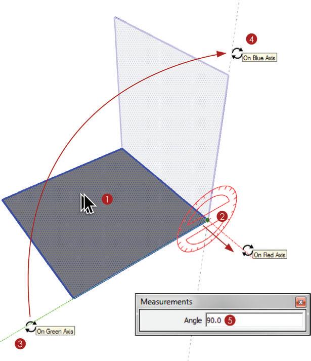
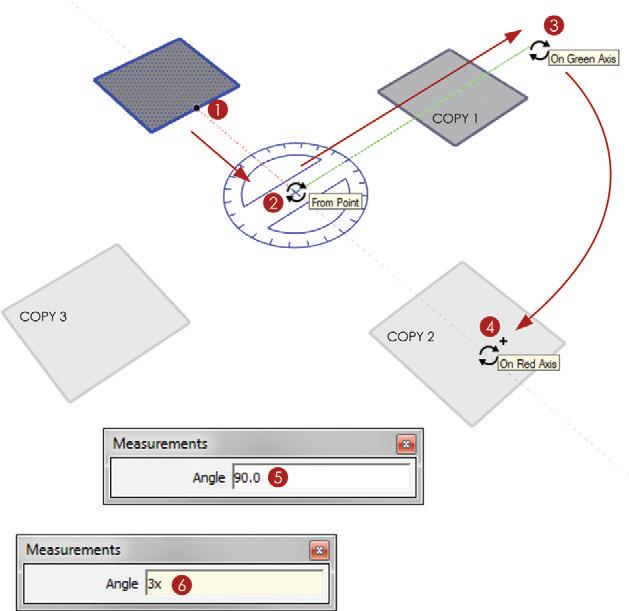
Similar to the Move tool, during any rotation, tap the Ctrl key (Option on Mac) to toggle on the Copy command. This will leave a copy of the selected object behind (Figure 40.41). To perform a polar copy and array, follow these steps:
1. Pre-select the entity you wish to rotate and copy. Activate the Rotate Tool, hover on a point to encourage an inference and use a meaningful starting point.
2. Click and drag and release on the blue axis.
3. Move your cursor to the right and click once to set the reference line. Tap the Ctrl key (Option on Mac) to toggle on the Copy command while you move your cursor down the screen.
4. Click to place the copy.
5. Immediately type a precise degree of rotation, such as 90 , then press Enter.
6. To make three copies, immediately type the number of copies as 3x , then press Enter. You can continue to change both the degree of rotation and the number of copies until you invoke another command.
TIP Similarly to the way you use the Move tool, you can also enter the overall copy rotation and specify divisions. for example, after making a copy type 180, then press enter, immediately type 5/, then press enter. This will make the original copy at 180 degrees and fill the space between with five divisions.
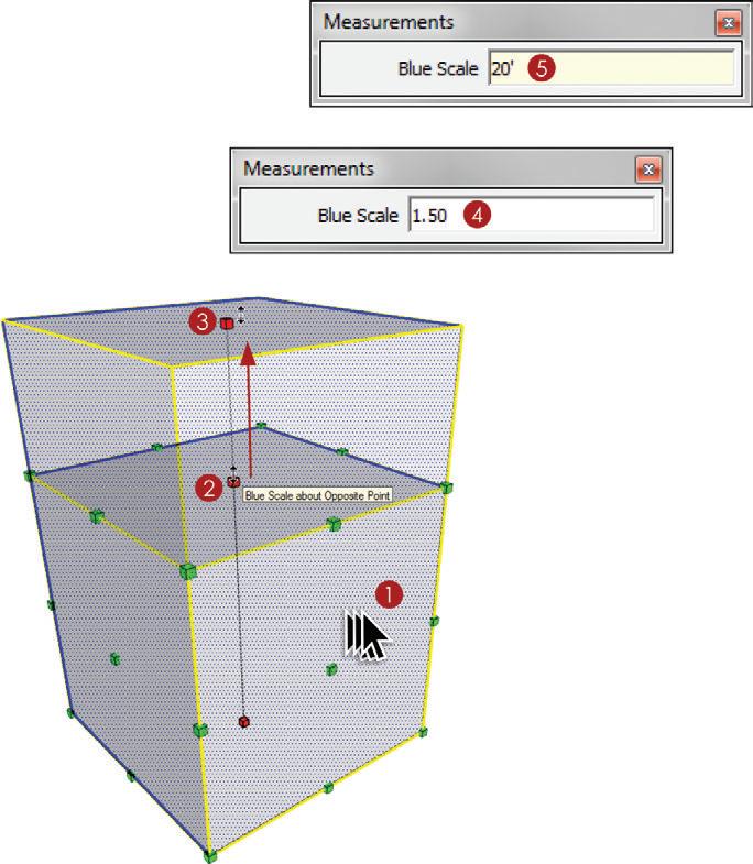
Scale Tool
The Scale tool distorts entities based on a scale factor or a “hard” dimension. The hot spot of the Scale tool is at the tip of the red arrow, but it usually is best to preselect entities before scaling. Follow these steps:
1. Using the Select tool, preselect the entity you want to scale.
2. Activate the Scale tool and click on the top center grip.
3. Move your cursor to scale the object and click to finish the command.
4. Immediately enter a scale value, such as 1.5 , then press Enter.
5. You can also type a precise dimension into the Measurements dialog—for example, 20 ', then press Enter. Be sure to specify feet or inches because the Scale Tool defaults to a scale value rather than the models default units (Figure 4.42).
TIP The Scale tool also has modifier keys to help you achieve the desired scaling effect. hold the Shift key to toggle between a uniform and nonuniform scale. hold the ctrl key (option key on Mac) to scale about the center of the entity.
Offset Tool
The Offset tool concentrically copies a series of connected edges or a surface’s bounding edges (Figure 4.43). Follow these steps:
1. Use the Select tool to preselect a series of connected coplanar edges, or use the tool’s hot spot at the tip of the red arrow to auto-select a surface and offset its bounding edges. Hover on an edge to set the starting point.
2. Move your cursor to suggest the direction of the offset and let go of the mouse.
3. At this point, you can type a precise dimension, such as 2', then press Enter.
A DVA nce D i nferencing
The inference engine is always running in the background and is there to help keep your geometry aligned in accurate and meaningful ways. Mastering inferences is essential to fast and efficient drafting in SketchUp. The inferences discussed in this section are advanced techniques; becoming familiar with each of these inferences will make you much faster at drawing in SketchUp. Try to think of ways to eliminate clicks from your own modeling techniques. Often, inferences can eliminate guides and clicks. Many of the following inferences work with both the Drawing tools and the Move tool.

TIP The inference engine cannot be turned off, but why would you want to? once you master the available inferences, you will wonder how you ever lived without advanced inferences.
Multiple Points
You can encourage an inference from a point, a midpoint, or even two points (Figure 4.44). Follow these steps:
1. With the Line tool active, hover on an endpoint until you see the Endpoint notification. When you see the notification, the edge is loaded into the inference engine. Move your cursor away from the point and you will see a dotted inference line representing the axis it is on.
2. Hover on another endpoint until you see the Endpoint notification. When you see the notification, the edge is loaded into the inference engine. Move your cursor away from the point and you will see two dotted inference lines projecting from the two inferenced points.
3. Click where the inference lines meet to start the line at a meaningful point. Now you can go on to encourage more inferences and click to finish.
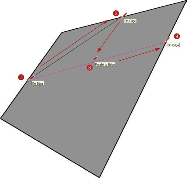
Parallel to edge
Draw parallel to an existing edge by encouraging a Parallel to Edge inference (Figure 4.45). Follow these steps:
1. Click once to start a line.
2. Position your cursor on the edge to which you want to draw a line parallel. Wait for the On Edge inference to appear; this lets you know that SketchUp loaded that edge into the inference engine.
3. Position you cursor roughly parallel to the edge. The active line will turn magenta and you will see the Parallel to Edge notification appear. At this point you can hold down the Shift key to lock the inference.
4. Position your cursor over a point, edge, or surface to specify the distance and click to finish.
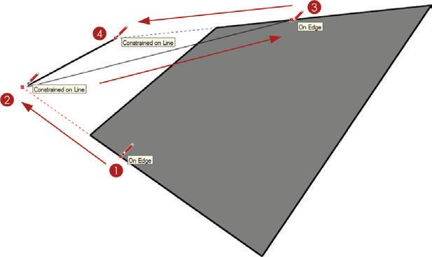
The Edge Constrained inference allows you to either start or finish an operation along a specific edge (Figure 4.46). Follow these steps:
1. Using the Line tool, hover on an edge. When you see the On Edge inference, hold down the Shift key.
2. Move your cursor off of the existing geometry and notice that the starting point is constrained on the edge. Click to start the line.
3. Hover on another edge. Once you see the On Edge inference, hold down the Shift key to constrain the next point along that edge.
4. Click to finish the line.
TIP you can also constrain an operation on a surface by first hovering on the surface and then holding the Shift key. This will limit any line that you draw to be coplanar with the inferred surface. constrained inferences, both edge and surface, are especially helpful when you’re working out complex roofs in three dimensions.
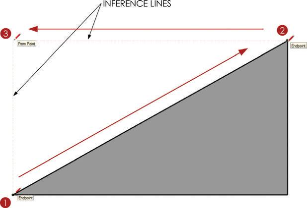
Line Intersect
Use the Line Intersect inference to take the place of guides and project intersections between lines (Figure 4.47). Follow these steps:
1. To encourage the inference, use the Line tool to hover on an endpoint until you see the Endpoint inference notification.
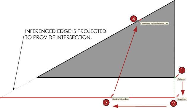
2. Move your cursor down away from the Endpoint on the green axis and click to set the starting point.
3. Move your cursor to the left until you find the red axis. Once the active line turns red, hold down the Shift key to lock the axis.
4. Position you cursor on the angled line. The endpoint of the line has been projected to the intersection of the locked axis and the inferenced edge. Click to finish.
o rg A nizing g eo M e T ry W i T h c on TA iner S
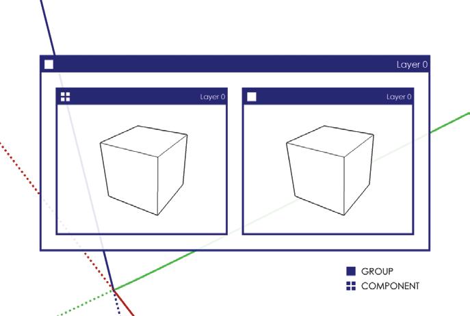
SketchUp has two basic containers for geometry: groups and components (Figure 4.48). These containers not only separate edges to control stickiness, but also organize entities and geometry to make more efficient models. Groups are unintelligent containers that have no connection between copies. Groups simply hold geometry. Components on the other hand have intelligence in that each instance is connected. If any instance of a component is modified, all instances of the same component reflect those changes as well.

TIP in this book, the term container refers to both groups and components.
Groups
Groups are unintelligent containers that simply hold geometry (Figure 4.49). If you make a copy of a group, there will be no connection between the original and the new copy. Almost every object should be made into a group. It is almost impossible to make too many groups.
Groups are mainly used to contain entities, form a hierarchy of layers, and control the stickiness of geometry.
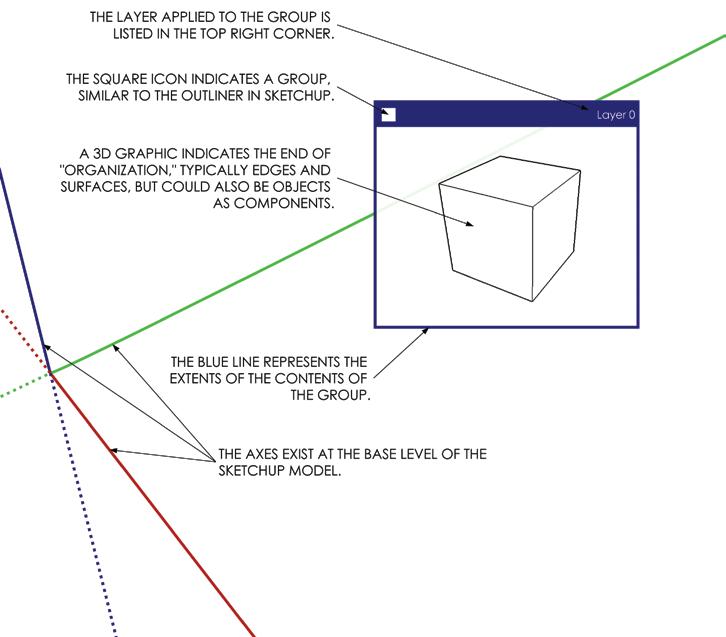
The organization techniques utilized during The SketchUp Workflow for Architecture require advanced layering and organization of groups. Model organization diagrams (Figure 4.50) are used to complement the text and further explain layering and grouping.
Creating a Group
To create a group, follow these steps:
1. Using the Select tool, select at least two entities (edges, surfaces, groups, or components).
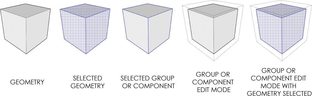
Figure 4.49 Groups can hold any entity created in SketchUp. When selected, both groups and components highlight with a blue bounding box.
2. Right-click on the selection and choose Make Group, or click on the Edit drop-down menu and choose Make Group.
Components
Unlike groups, components are intelligent containers. They hold geometry just as groups do, but there is a linkage between all copies of a component. Suppose you make a component and then copy it several times throughout a model. If you edit any one instance of a component, all instances of that component will update simultaneously to reflect those changes (Figure 4.51).
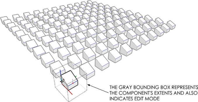
Components are used to make extremely efficient models. When you see repeating elements, similar elements, and lines of symmetry, you should think component.
TIP A component's behavior is similar to a block in cAD, or a smart object in Adobe Photoshop.
Creating a Component
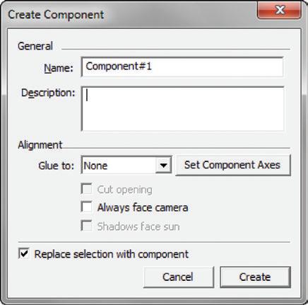
To create a component, follow these steps (Figure 4.52):
1. Using the Select tool, select at least two entities.
2. Right-click on the selection and choose Make Component.
3. In the Create Component dialog, assign the desired properties and choose Create. Figure 4.52 The
TIP if you are making a copy of a group, it should most likely be made into a component first. To change a group into a component, right-click on the group and choose Make component. it is easier to make a group first, and then choose Make component because this method bypasses the often unnecessary create component dialog.
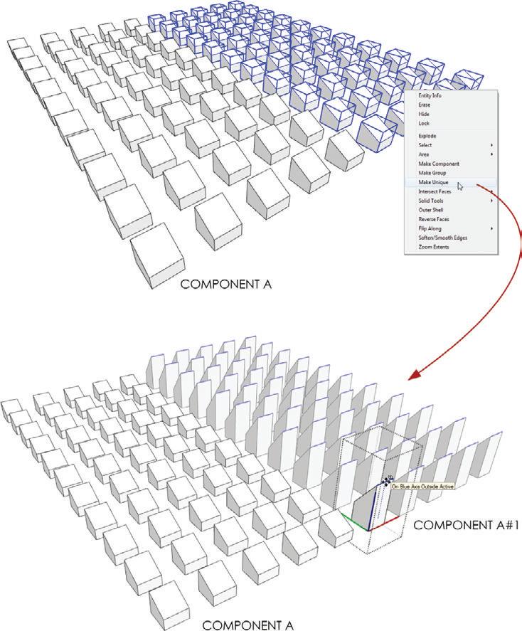
Making Unique Components
The Make Unique command is used for similar elements. It is similar to a Save Copy As command in other programs. The original component instance(s) are left connected and intact, and a new component instance is created based on the selected component (Figure 4.53). To make a component, or multiple components unique, select them, then right-click on the selection and choose “Make Unique.”
Figure 4.53 Once a component or selection of components is made unique, the components are independent of the original instance and are connected only to each other.
Navigating Containers
The ability to quickly move in and out of containers is essential to fast and efficient modeling in SketchUp. The first way to navigate containers is slow and methodical. Use this method when you’re first learning to navigate containers; it is easy to understand which container level of the model you are in. Follow these steps:
1. Right-click on a container and choose Edit Group or Edit Component, depending on which type of container you are editing.
2. To close the container, right-click outside of the container bounding box and choose Close Group or Close Component.
A much faster method for navigating containers utilizes the Select tool. Use the Select tool method for navigating containers after you have a solid understanding of which container level of the model you are in. Follow these steps:
1. Using the Select tool, double-click on a container to move in one level (Figure 4.54).
2. To close the container, press the Esc key to back out while the Select tool is active. You can also click outside the bounding box of the container to back out one level.
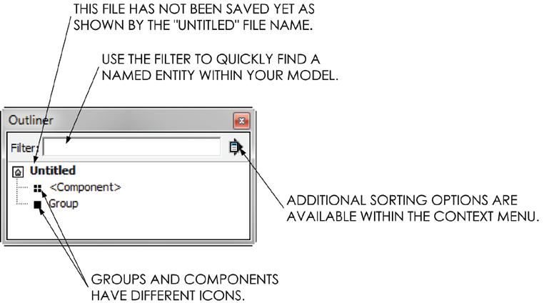
The Outliner shows a file-structure-type diagram of the contents of your model to help you find your way through the various container levels (Figure 4.55). To open the Outliner, click on the Window drop-down menu and choose Outliner. Click on entity names in the Outliner to select them. Double-click or right-click on containers within the Outliner to navigate in and out of the container.
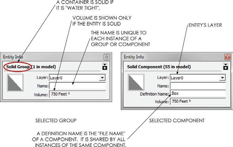
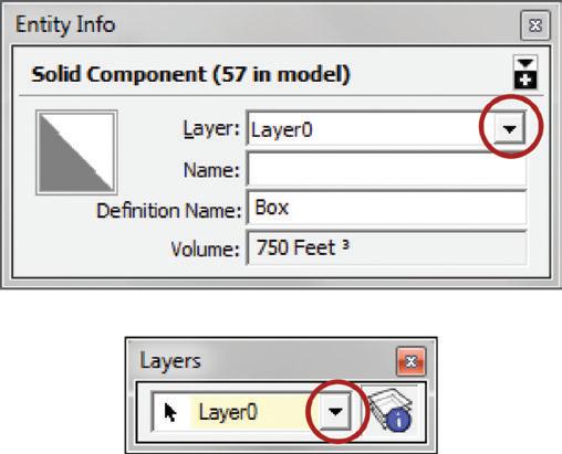
The Outliner is very helpful when all the groups and components in your model are accurately named. Groups and components can be named using the Entity Info dialog. To open the Entity Info dialog, click on the Window drop-down menu and select Entity Info (Figure 4.56). Then, use the Select tool to select an entity; its properties will be displayed in the Entity Info dialog where they can be edited. Make sure to assign logical names. For instance, if a group contains walls, name the group WALLS.
Modifying containers
Containers in SketchUp, including groups and more importantly components, can be modified without affecting the contents of the container. For instance, you can move and rotate a container without affecting the contents of the container. Remember, if you were to move or rotate the contents of a component, all instances would reflect that change. Rotating and moving are fairly easy concepts to grasp, but there are also more abstract ideas related to modifying containers covered in this section. In this section, you will learn to make components (and groups) different without actually affecting the contents of the component.
Move Tool
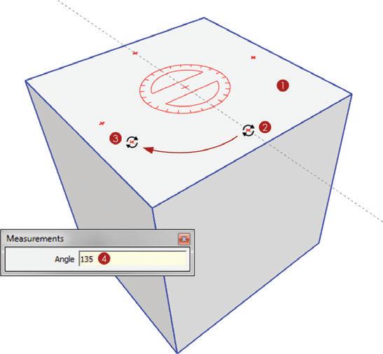
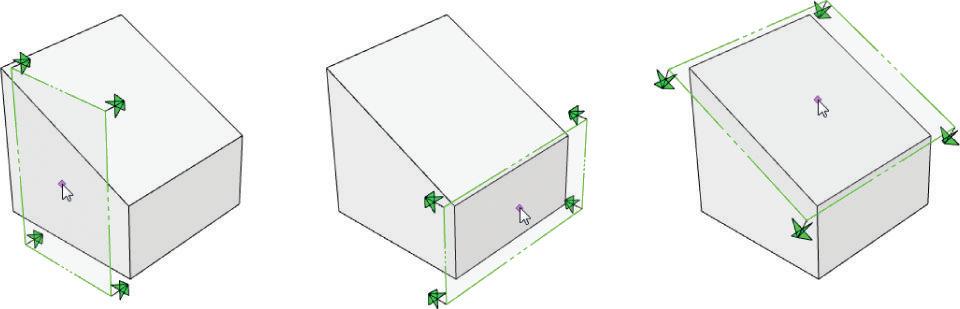
Use the Move tool to reposition containers exactly the same way you would reposition edges and surfaces. The Move tool also auto-selects entire containers and offers a rotate option (Figure 4.57). Just follow these steps:
1. Deselect all entities by right-clicking on the background, activate the Move tool and hover over a container. The Move tool auto-selects the container and displays red crosses on each side that you hover on.
2. Hover on one of the red crosses and you will see the Rotate tool positioned at the center of the container. Click once to start the rotation.
3. Move your cursor to rotate the container, then click again to define the actual rotation of the container.
4. At this point, you can enter a precise degree of rotation by typing 135 , then press Enter.
Figure 4.57 Auto-select a component with the Move tool and rotate. The contents of the container will not be modified.
Scale Tool
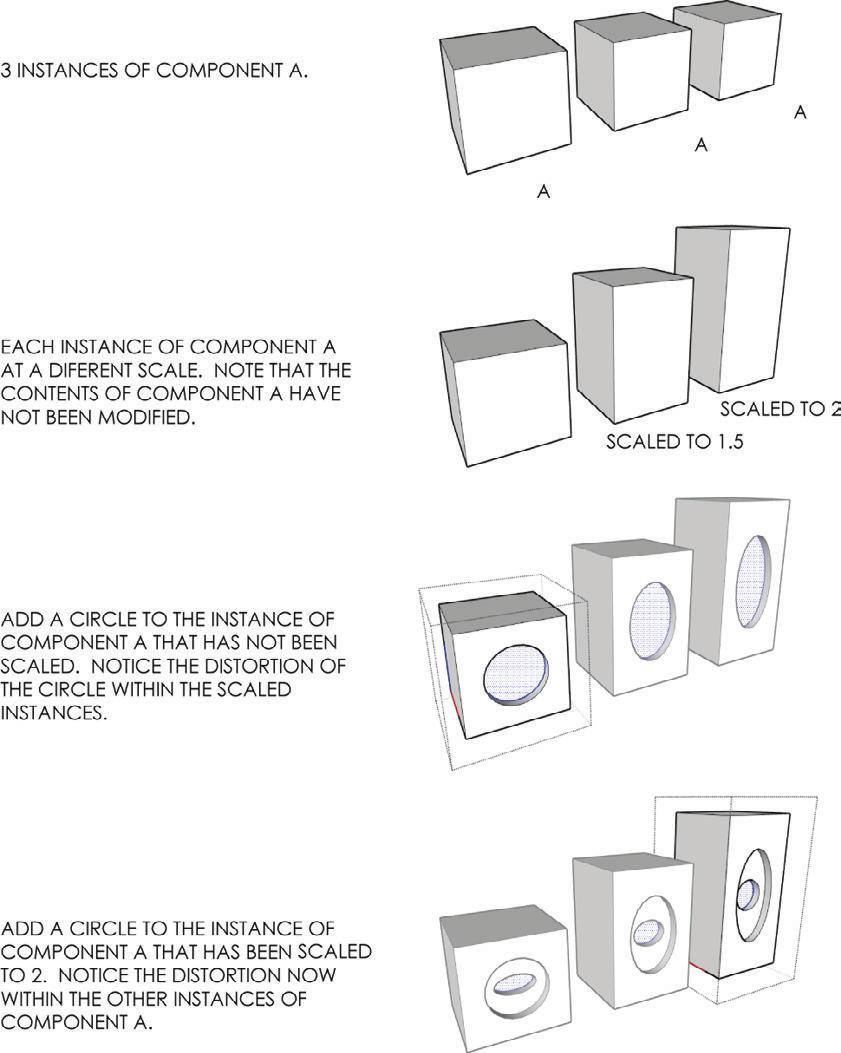
The Scale tool allows you to stretch and distort geometry, as well as containers. Scaling a container does not affect the contents of the container, so these changes will not be reflected in all instances of the component (Figure 4.58).
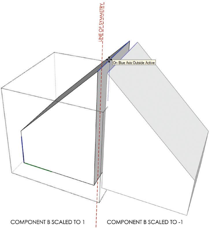
To create a line of symmetry, use the Scale tool and assign a scale factor of –1 to mirror the component (Figure 4.59).
TIP Scaling to –1 does the same thing as the flip Along command; however, the Scale tool is more visual and therefore easier to use. if you do choose to use the flip Along command, you can access it by right-clicking on an entity and choosing flip Along. Then you will have to define the axis along which you want to flip.
Default Material
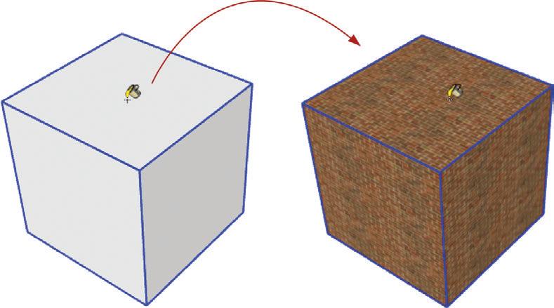
Any surface in a container that has the default material applied to it will take on the material of its parent (Figure 4.60). In other words, suppose there is a cube (six surfaces) in a container that has the default material applied to each surface. If you paint the outside of the group with a material, all the surfaces in the group will take on that material. This default material can be overridden by applying a different material to the actual surface in the group.
By leveraging the default material behaviors, you can have components that have efficiently linked geometry but display different materials. This characteristic can come into play when you use repeating elements that need to be slightly different. For example, you could have a chair component that is efficiently linked, but has a different colored cushion.
TIP At some point, you may try to right-click on a surface with a material applied to it and not see the Texture menu. if this happens, you are probably actually clicking on a surface that has the default material applied to it, within a group that has a texture image material applied to the outside of it. you can fix this by applying the desired texture image material directly to the surface.
Nested Containers
Nested containers are containers within containers within containers (Figure 4.61). There is virtually no limit to the number of “levels” deep your model can be. Mastering the concept of nested containers is essential to organizing for The SketchUp Workflow for Architecture. Select any two containers, right-click on the selection and choose Make Group or Make Component, depending on the desired container.
The need for nested containers depends on layering, repeating elements, and lines of symmetry. The organization techniques utilized during The SketchUp Workflow for Architecture require advanced layering and organization of nested containers, groups, and components. Model organization diagrams (Figure 4.62) are used to complement the text and further explain these layering and grouping strategies.

E Xplode
The Explode command could also be called the “Un-Container” tool. Right-click on a group or component and choose Explode to remove the container. Keep in mind that when a container is exploded, all entities previously within the container take on the layer previously applied to the exploded container.
Sec T ion Pl A ne S
The best way to open up a model and look inside is to use section planes. A section in SketchUp does not delete or modify geometry in any way; it simply hides geometry in front of the section plane. Follow these steps:
1. Activate the Section Plane tool.
2. Position the section plane on a face that is parallel to the desired section’s cut direction (Figure 4.63a).
3. Once you find the proper section orientation hold the Shift key to constrain it.
4. Continue holding the Shift key until you click again to place the section cut. You will now see the section plane hiding all geometry in front of it (Figure 4.63b).
Once a section cut is placed, it can be reversed, moved, rotated, copied, deleted, activated, and deactivated. Right-click on a section plane to access a helpful context menu. The Reverse command will flip the section plane to point the opposite direction. Check Active Cut on and off to activate and deactivate the section plane. Select Create Group from Slice to generate a group containing the 2D linework of the section cut.
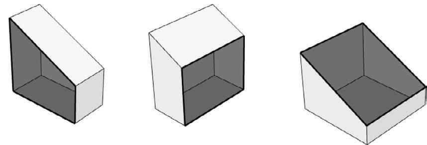
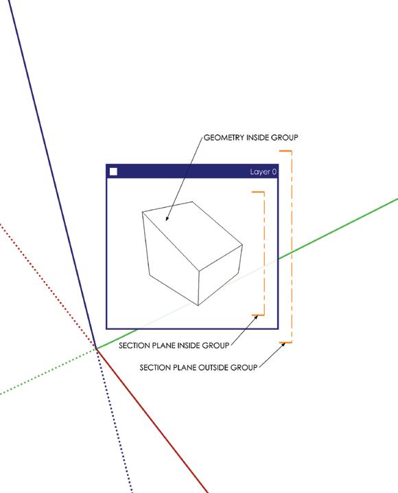
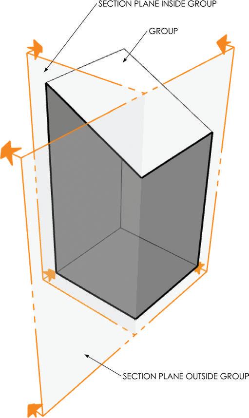
Only one section plane can be active at a time in each level of a model. If you want to have multiple section cuts, you must separate them into containers (Figure 4.64, Figure 4.65).
lAyer S , S T yle S , A n D Scene S
Layers, styles, and scenes are all related. Layers control the visibility of entities within SketchUp. Styles control the way in which entities are displayed in SketchUp. Layers and styles attach to scenes. So, by clicking on a scene, you can jump to a preset state for layers and styles, as well as several other properties that can be attached to scenes.
By mastering layers, styles, and scenes, you will gain full control over any drawing you want to create and you will become a faster modeler. In this section, you will learn the basic functions and operations of these features, and how they relate to each other. Later in this book, you will flex these features and leverage them to make more efficient models, presentations, and construction documents.
Layers
SketchUp layers are different than layers in many other 3D and 2D programs—but in a good way. SketchUp layers are simple. There is no stacking of layers in SketchUp, so the order in which layers are displayed in the Layers dialog has nothing to do with the way in which geometry is displayed in your SketchUp model. Layers can be assigned to any entity in SketchUp, including edges, surfaces, groups, and components. You are only able to control whether or not a layer is visible and the color of the layer when on a color-by-layer style. That’s it!
Click on the Window drop-down menu and choose Layers. The Layers dialog is where you set the current layer, visible layers, and layer colors; it is also where you add, delete, and rename layers (Figure 4.66).
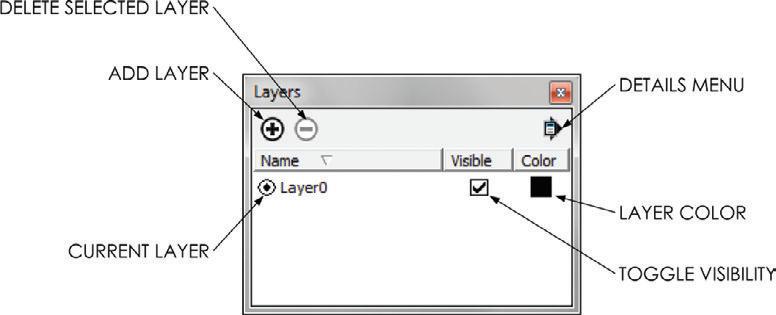
The current layer, defined by the dot to the left of the layer name, should always be set to Layer0. Layer0 cannot be deleted or renamed. Any entity created within or added to the model will be assigned to the current layer, Layer0. It is possible to change the current layer, but doing so is not advisable. The workflow presented in this book requires that all edges and surfaces be drawn on Layer0. So, it is best to always leave Layer0 as the current layer. To work with layers, follow these simple guidelines:
☑ To add a layer, click on the plus sign (+) in the top-left corner of the Layers dialog. Once a new layer is created, you can immediately rename the layer by typing over the blue highlighted text and pressing Enter to finish.
☑ To rename a layer, double-click on the layer name and type over the blue highlighted text, then press Enter to finish.
☑ To delete a layer, first click on the layer name to select it. Then, click on the minus sign (–) in the top-left corner of the Layers window to delete it. If there are entities on the layer you are deleting, you will be asked “What to do with the entities.”
☑ Click on a layer’s color swatch to change it. A layer’s color will only show when on a color-by-layer style.
☑ Click on the check box next to a layer in the Visible column to toggle the layer’s visibility on and off.
☑ To organize the list of layers by name, visibility, or color, click on the headings at the top of the columns.
☑ To assign an entity to a layer, rightclick on the entity and choose Entity Info. Within the Entity Info dialog box, click on the Layers drop-down menu and choose a different layer. A Layers toolbar is available by clicking on the View drop-down menu and choosing Toolbars c Layers. The Layers toolbar works the same way as the Layer dropdown menu in the Entity Info dialog (Figure 4.67).
Once the Entity Info dialog and the Layers toolbar are open, you can simply select an entity and adjust its layer in one of these dialogs. There is no need to right-click on the entity every time.
Styles
Styles provide a different way to look at your model. Styles do not affect geometry; they are simply a unique set of lenses for looking at your model. You can make the model edges sketchy, change the color of the sky, make all faces render as the same color, and use many other attractive visual settings without actually affecting any edges or surfaces.
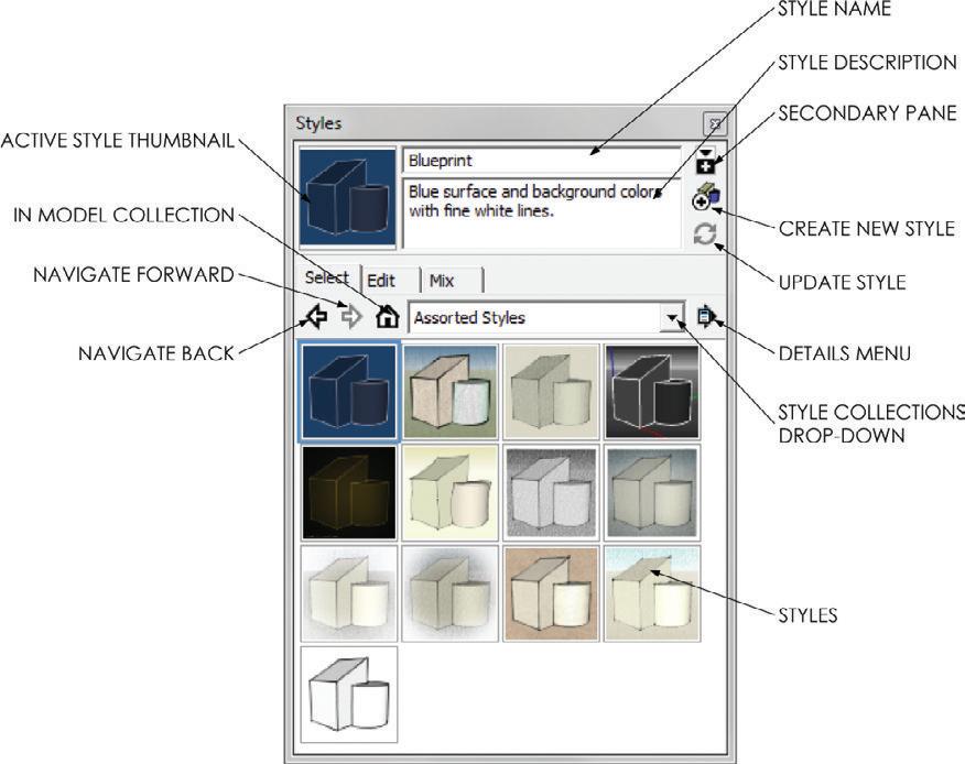
To open the Styles browser, click on the Window drop-down menu and choose Styles. Within the Styles browser, you can select from preloaded styles by clicking on the Libraries drop-down menu (Figure 4.68). Once you find a style you like, click on it.
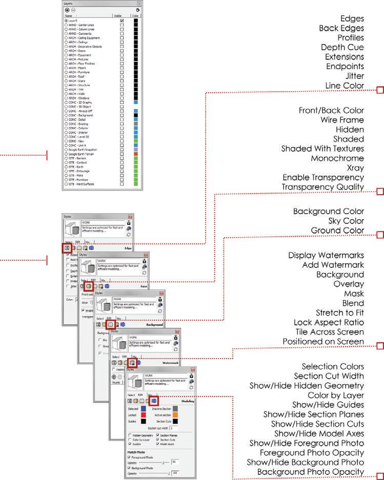
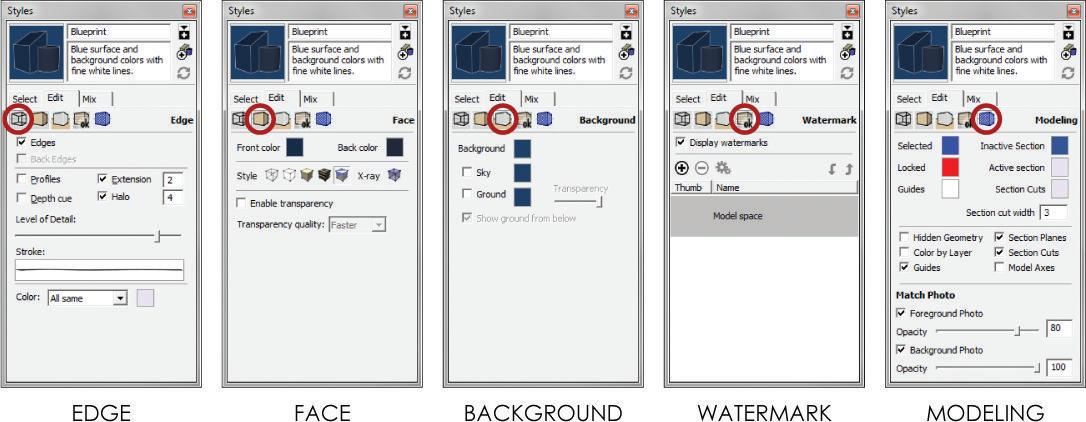
To change the properties of a style, click on the Edit tab. Five boxes in the Edit tab represent Edge, Face, Background, Watermark, and Modeling settings (Figure 4.69). Try changing a few of the settings and see how the display properties of the geometry in your model are affected.
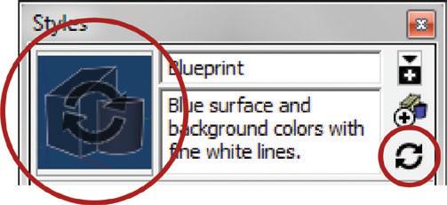
Changing any of the Style properties means that the style is now out of date. A “recycle” watermark will appear on the active style’s thumbnail image. In order to save any changes you’ve made, you must update the style by clicking on the Style thumbnail or on the Refresh button in the Style browser (Figure 4.70). If any property of a style is changed, the style must be updated to save the changes.
Use the Mix tab to make your own unique Style creations. See “Chapter 7: SketchUp Collections” for more information on using the Mix tab.
TIP it is possible to change many of the Style settings using drop-down menus. for instance, if you click on View c Axes and turn off the Axes, that is actually a Style setting. you must be aware and update the style within the Styles browser if you want to save that change.
Scenes
Scenes are most often associated with a camera. In other words, most people assume that a scene is just like a bookmark for a specific view of your model. This is true, but scenes also save many other properties in addition to the camera location. Scenes can also save hidden geometry, visible layers, active section planes, style and fog, shadow settings, and axes locations. By creating complex scenes, you can create any rendering, drawing, or diagram that you need.
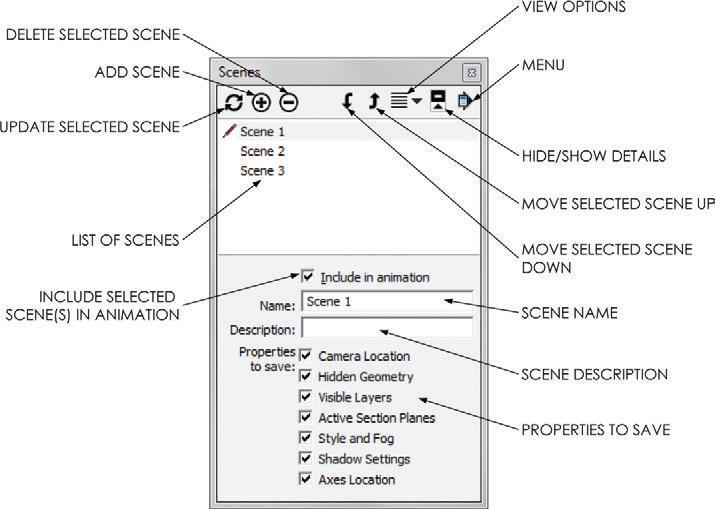
Take a look at the Scenes browser by clicking on the Window drop-down menu and selecting Scenes. The Scenes browser is where you will add, name, delete, and update the scenes in your model (Figure 4.71).
In the Scenes browser, you can see that scenes have a name, description, and properties to save. The name of a scene will appear in the Scene browser as well as on the corresponding Scene tab at the top of the screen. The description of a scene, which is usually unnecessary, is displayed in the Scene browser and also when you hover your cursor over a Scene tab. The Properties to Save are the critical attributes of scenes (Figure 4.72). The check boxes next to the properties control whether or not the selected scene will hold onto the named settings. For example, if the Camera Location property is not checked on to be saved, there will be no camera location information associated with that scene.
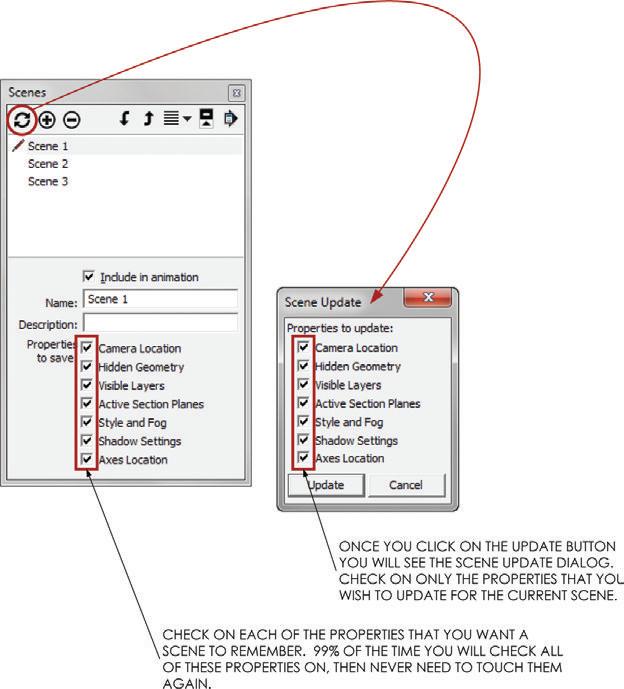
Frequently, the Properties to Save are confused with the Properties to Update. Remember, 99 percent of the time you will want all of the Properties to Save checked on, and you will never need to touch them again once the scene is created. When you want to modify the scene, click on the Refresh button and check and uncheck the desired Properties to Update.
Similar to styles, scenes also need to be updated if you want to save any changes to the scene. The tricky thing about scenes is that there is no visual cue that that tells you the scene needs to be updated.
Typically, the only time you would uncheck certain properties within the Properties to Update dialog is when you are applying aspects of one scene to another scene. For instance, to match the camera view from one scene to another, first go to the scene with the desired camera view by clicking on its scene tab. Then click on the scene you want to have the same camera view within the Scenes dialog. Click on the Update Scene button and uncheck everything but the Camera Location in the Properties to Update dialog. Click on Update and the two scenes will have the same camera location.
combining layers, Styles, and Scenes
By combining layers, styles, and scenes, you can completely control a model. Experiment with all of the settings shown in the following diagrams until you have fully mastered them (Figure 4.73, Figure 4.74).
Keep these tips in mind when you’re working with layers, styles, and scenes:
☑ When you’re creating scenes, it is usually best to change all of the desired settings so that your screen looks the way you want the scene to look. Then you add the scene to take a digital “snapshot” of the settings that make the screen look that way.
☑ If you decide to change a property that is saved within a style, you will need to update the style. You do not need to update the scene after making changes to a style if the style is already attached to the scene.
☑ When you’re creating a scene, most of the time you will want to have all of the Properties to Save checked on. After checking them on, there is almost never any reason to go back and uncheck them.
☑ If a Property to Save is unchecked, that property won’t be saved with the scene. For instance, if the camera location is unchecked, then no matter how many times you click on that scene or update it, it will not take you back to a camera view. The camera location must be checked on in Properties to Save in order for the scene to remember the camera location.
☑ If you decide to change a property that is saved by a scene, and you want the scene to reflect those changes, you will need to update the scene. Typically, it is safest to make the adjustments, click on the Update button, then uncheck all properties in the Properties to Update dialog, except the properties that you have changed.
☑ If you need to modify the properties of a scene, you’ll be better able to keep track of what you’re doing if you first click on the Scene tab to see all of the Scene settings visually presented on your screen. Make only the changes that you want, and then right-click on the Scene tab and choose Update to update all of the properties at the same time. This can be dangerous if you don’t completely understand how to use scenes, but it will ultimately save you time because you’ll avoid the Properties to Update dialog and all of the checking and unchecking.
c h APT er Poin TS
☑ SketchUp is a surface modeler, which means its basic building blocks are edges and surfaces. All shapes in SketchUp are composed of edges and surfaces; there are no true solid shapes such as spheres, cubes, and cylinders.
☑ Inferencing and axis locking allow you to interact with the 3D SketchUp environment effectively through your 2D computer screen.
☑ Typically, you should start with a Drawing tool that adds surfaces, such as the Rectangle tool, Polygon tool, or Circle tool.
☑ Use Drawing tools that only add edges to set up slight additive and subtractive adjustments.
☑ Use the Modification tools to turn simple forms into complex geometry.

☑ When you’re creating components, look for repeating elements. If you need a similar element, use the Make Unique command. Mirror a component container using the Scale tool or Flip Along command to create lines of symmetry.
☑ Layers, styles, and scenes are absolutely necessary for creating a useful SketchUp model. To avoid frustration in later chapters, you should explore these combined concepts until you completely understand how they work before you proceed.
☑ The best way to learn about layers, styles, and scenes is to review this chapter while playing around with their settings. Don’t be afraid to make a copy of a model and mess it up by experimenting.