
13 minute read
Chapter 18 Schematic Design


Duringthe schematic design (SD) phase, you interpret the site analysis (SA) data and develop the initial draft presentation of your design ideas. In this section, you will learn how to efficiently organize your model for rendering, sharing with consultants, exporting to other CAD programs, and preparing for construction documents.
r e M o D el De S ign
Advertisement
Now that you’ve collected all the data during the SA phase, it’s time to utilize it. In this section, you’ll further develop the 3D as-built model and transform it into a design model. Working with existing conditions lends itself to precise modeling. If you are working from an accurate as-built, there is no need to convolute it with new inaccurate “sketchy” geometry. Stick with the plan and continue to treat this model as a pristine, accurate, and organized model.
Proposed conditions Model
The proposed conditions model is where you will demolish select existing conditions and add your new design. At this point, having a complete existing conditions model is imperative. In the future, any changes you make to the existing conditions model will need to be duplicated in your new proposed conditions model. So make sure you take the time to accurately finish the as-built model. When you are ready to transition your existing conditions model to a proposed conditions model, just follow these steps:
1. In SketchUp, open the BIC_3458 Steele St – Existing Conditions.skp model from Chapter 17, “Site Analysis: Documenting an Existing Building.”
2. Click on the File drop-down menu and select Save As.
3. Name the file BIC_3458 Steele St – Proposed Conditions.skp
4. Navigate to your TEMP folder or the appropriate project folder and click the Save button.
Demolition
Often, you will need to demolish portions of an existing building in order to complete your renovation. Within the model, simply remove the walls you want to demolish and delete any entities you do not want as part of your design.
If at some point you need to restore a demolished entity, you can copy it from the existing conditions model and paste it in place in the proposed conditions model. For walls, it is fairly intuitive to just redraw them in the existing container.
There is no need to save anything that is being demolished in the proposed conditions model. You will see in Chapter 20 “Construction Documents” that the the demolition plan is a product of the existing conditions model combined with the proposed conditions model.
New Construction
To complete the design, you’ll need to add new walls and entities to your model. To do that, all you need to do is add one more layer “switch”, or level of organization to the model. Within each of the ARCH groups, at the same level as the CONC – Existing container, add a container assigned to the CONC – New layer. This is where you will add new entities based on the container on which you are working (Figure 18.1). Add a CONC – New container to each of the ARCHITECTURAL layers as you are adding the new entities.
Scope Diagram
When you’re working on a remodel design, you can view the model as a Scope Diagram to see which entities are new and which are existing (Figure 18.2). This will help you make informed design decisions visually, without always having to check the layering of the model. Open the completed BIC_3458 Steele St - Proposed Conditions.skp model from the chapter files. Click on the scope diagram’s Scene tab and explore the model’s organization strategies and layering.
Pro J ec T Ty P e S
Every project requires different layers, different containers, and different organizational strategies. It is always best to think through your project’s requirements before you start the model. When you approach and organize your models, keep the following tips in mind:
☑ Identify the layers your model will need based on what drawings you need. If you don’t need a Finish Plan, you might not need to use the ARCH – Floor Finishes container and layer. If your model has only one floor, you won’t need the CONC – Level 00 layers.
☑ A new construction project will not need the CONC – Existing or CONC – New layers because everything will be new.

☑ A rowhouse model might have several layers for the units, such as CONC – Unit A, CONC – Unit B, CONC – Unit C, etc.
☑ A campus model might have several layers for individual buildings, such as CONC –Building 1, CONC – Building 2, CONC – Building 3, etc.
☑ One of the simplest project types would be a one-level new-construction project.
☑ One of the most complex project types would be a multilevel, multiunit remodel.
☑ Think of each of the ARCH and SITE layers as nouns and the CONC layers as adjectives that describe the ARCH and SITE entities.
☑ Become comfortable with your location in the model. Pay attention to visual cues that identify the organizational levels of your model. Practice navigating the groups and components (use the Select tool, double-click, and the Esc key).
It is impossible to create one template that accommodates every project type. This means you’ll be adding layers to almost all the new models on which you work. When you use the Layer dialog to add a layer, the newly added layer is visible by default in every scene. When you use the Add Hidden Layer ruby (see Chapter 8, “Ruby Scripts”), the new layer will be invisible in all existing scenes, which is more desirable.
Models have different needs. Visit www.suexch.com/tSWFa to see several models and model organization diagrams that represent different project scopes and types.
Mo D eling S T r AT egy
At this point, it should be very clear that you can be very loose and sketchy in SketchUp, or you can be accurate and precise. Just as each project type has a unique organizational strategy, each project type has a unique modeling strategy. There are two schools of thought: model sketchy and then clean up, or model precisely from the beginning. There is no one right way to design in SketchUp, but some of the suggestions presented here can help you determine how SketchUp is best leveraged.
Sketchy Modeling
If you model without paying attention to precise dimensions, you are creating a throw-away model. When you create sketchy models, the amount of effort you’ll need to edit the loose geometry back into precision is not worth the time it would take. Typically, it is easier to rebuild the design in a new file after you have poured your thoughts into the sketchy model. If you are going to model in this way, keep these tips in mind:
☑ Turn on length snapping to make the sketchy dimensions snap to a clean, round number. This will make it a little easier to transition if you are cutting and pasting into your precise model.
☑ Group everything! Once geometry is stuck together, it becomes much more difficult (but not impossible) to sort it all out.
☑ Assume that your sketchy model is going to be a throw-away model. Usually, it takes more effort to edit the geometry back into precise dimensions than it would to rebuild the model.
☑ During the Schematic Design phase, create a programming diagram, mass models, and quick plan sketches without being too hung up on precise modeling practices.
☑ A new construction project lends itself to brainstorming on a larger and freer scale, and sometimes without paying close attention to precise dimensions. Because you aren’t limited by the constraints of an existing building, you are free to develop any style and space plan you desire.
Precise Modeling
Modeling with exact dimensions right from the beginning is the best method. Even though it is easy to push, pull, move, and scale without being precise, there is really no reason to do that. Keep your dimensions clean from the beginning by organizing your model and performing accurate operations. If you are going to model in this way, keep these tips in mind:
☑ If you have used a sketch model, or concept, then start a new file to create the SD/DD/ CD model.
☑ Move groups, components, and entities between groups and components and even other files using the Paste in Place command. Copy or cut a selection, and once you are inside the desired model or container, click on the Edit drop-down menu and choose Paste in Place.
☑ From the beginning, a remodeling project lends itself to precise modeling because you need to work within the constraints of the existing construction.
level of Detail
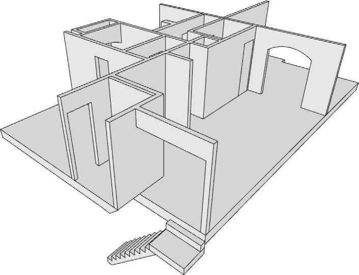
You need to determine the level of detail that should be included in your models. If you are creating a building model to be used for design, presentation, and construction documents, you should think in terms of 1/8 g plans. Typically, generic wall thicknesses provide plenty of detail, either to studs or including gypsum board. You don’t need to model layers for drywall, studs, or plates in the main design model; you only need to include generic thicknesses and openings (Figure 18.3). Excessive detail is usually unnecessary, and it will slow you down. You can describe any detail beyond that in a detail drawing, detached from the main, proposedconditions, design model.
oBJ ec TS
Approaching and modeling objects is a challenging task. Typically, everyday objects that make a convincing scene are “organic” in shape. Many modelers approach these objects with the standard SketchUp modeling tools, which ultimately creates a hard-lined object that was obviously modeled in SketchUp (Figure 18.4). When you’re modeling objects, keep the following tips in mind:
☑ Examine the object to determine the details that make it unique and recognizable.
☑ Think about your approach. What basic forms can be modified to create the desired object? Is an additive approach the best? Or would the subtractive approach be better?
☑ You will probably come to the conclusion that it is worth it to pay for professionally built models of objects at www.formfonts.com Many objects have a 3D form that produces the correct graphic when it is rendered in a plan— for example, couches, sinks, counters, and toilets (Figure 18.5).

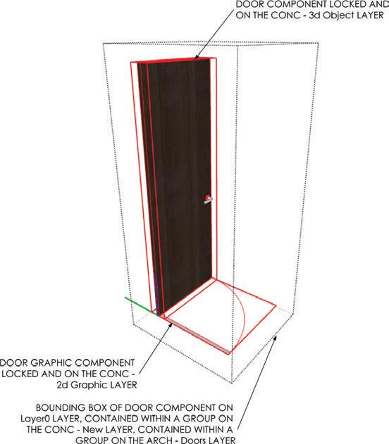
There are also many objects that have a 3D form that does not render correctly in plan. Some examples are doors, upper cabinets, and electrical outlets. To help you understand this concept, realize that a door shown in plan has a very graphical representation (Figure 18.6). Slicing through a three-dimensional door with a section plane will not produce the graphic you need for a plan. For any object like this, there will be a 3D object that will be visible in perspective and elevation views, and a 2D graphic that will be visible in plan views (Figure 18.7).

eXP or T ing T o c AD
At some point you may want to move your SketchUp design into your favorite CAD program. The Model Organization tools in this book make it simple to export your design as a 2D or 3D model—and share your design with consultants so that engineering drawings can be completed. Typically, consultants do not work with SketchUp, so you will need to either export to a 3D format they can work with or to a 2D format that is easily adapted to their layering system.
e xporting 3D
Exporting your SketchUp model to another 3D model format is the easiest way to communicate with other programs. Depending on your needs, this method does not always
Chapter 18: Schematic Design provide the flexibility needed to utilize the model. If you do want to export to another 3D format, follow these steps:

1. Within SketchUp, click on the File drop-down menu and select Export c 3D Model (Figure 18.8).
2. Click on the Export Type drop-down menu and select the desired format. You can export to several formats, including .dae, .kmz, .3ds, .dwg , .dxf, .fbx , .obj, .wrl , and .xsi.
3. Click the Options button to adjust specific settings relating to the file type you are exporting. They will be different for each export file type.
4. Navigate to the TEMP folder (or the appropriate EXPORTS folder), add a YYMMDD folder, and then click the Export button to finish. A 3D model export maintains all layering and grouping; component instances are turned to blocks and maintain their connectivity.
TIP exporting to revit is the elusive holy grail of SketchUp workflow efficiency. The problem is that revit is a completely different type of program than SketchUp. There is no clean, seamless import workflow that pulls all the intelligence from SketchUp and translates directly into the revit format. Think about everything you have learned about the way that SketchUp works. There are no walls, floors, doors, or windows in SketchUp. you know what these entities are because you are putting them in containers and assigning layers. SketchUp can’t communicate them to revit because revit actually has walls, doors, and windows. The best thing to do is import the 3D model as a mass and trace it in revit. Another option is to import the 2D cAD drawings and trace those while applying the entity properties.
e xporting 2D
Typically, you export to 2D CAD to move into another CAD program, or you might just need to share 2D CAD backgrounds with other consultants. A major benefit of 2D CAD is that it is fairly fast and easy to use, and almost everyone in the design field knows how to use it. Sometimes you just need to get the job done. It is okay to think and design in SketchUp 3D, and then refine and document your design in a familiar 2D CAD program. The SketchUp Workflow for Architecture is extremely flexible, so don’t hesitate to abandon ship at this point and use another program if that is what works for you.
Exporting to 2D CAD that everyone can use has different challenges. The main one is that the layers in most CAD programs are not set up the way they are in SketchUp. You can get around this by exporting 2D DWGs from SketchUp to CAD by layers or line weights. You will export once for the doors, windows, walls, fixtures, etc., and then export another set based on new and existing (Figure 18.9).

Creating the Export Model
If at all possible, you should always reference the proposed conditions model into another file in order to export the 2D backgrounds. Doing so limits the number of Scene tabs and clutter within the main design model. Follow these steps:
1. Start a new SketchUp model.
2. Within SketchUp, click on the File drop-down menu and choose Import.
3. Navigate to and select the BIC_3458 Steele St – Proposed Conditions.skp model. Click the Open button to finish the import.
4. Save the model as BIC_3458 Steele St – Backgrounds in the appropriate project folder.
Creating Scenes
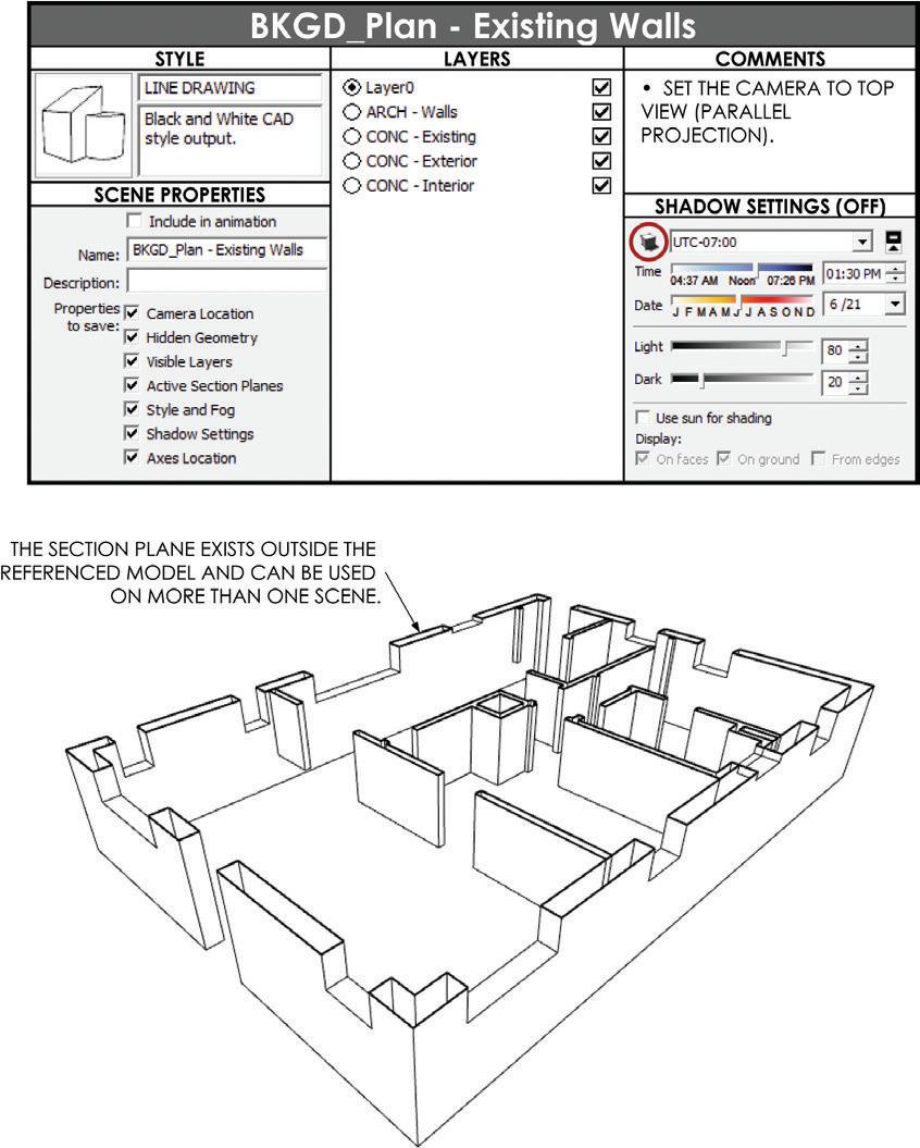
Now it’s time to set up the scenes that represent each piece of the .dwg backgrounds. You can visualize the scenes using a SOD (scene organization diagram) for the existing walls (Figure 18.10) and a SOD for the new walls (Figure 18.11). The 3D views shown in the figures are in perspective for effect; they will actually be top-down parallel projection views.
1. Adjust the layer visibility, style, and shadow settings to reflect the desired background export.
2. In the Scenes dialog, click on the plus sign (+) to add a new scene.
3. Repeat this process for each desired background export.

TIP every scene you create must have the same camera view. To ensure that they are all the same, set the camera view to top, select all of the BkgD scenes in the Scenes dialog, and then click the Scene Update button; update only the camera view and uncheck all other properties. click Update. now all the scenes have the same camera view.
Exporting 2D Graphic
Now that you have scenes created, export them to a .dwg for use in other CAD programs.
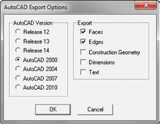
1. Click on the File drop-down menu and choose Export c 2D Graphic (Figure 18.12).
2. Click on the Export Type drop-down menu and choose .dwg .
3. Click on the Options button to open the Export Options dialog. Set the format to ACAD 2000. (The year 2000 is a pretty good year for compatibility between software packages and CAD versions. If you know exactly the version you need, choose it instead.)
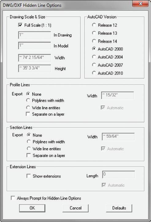
4. Navigate to the appropriate EXPORTS folder, and add a folder with today’s date in the YYMMDD format to keep things organized.
5. Click the Export button to finish.
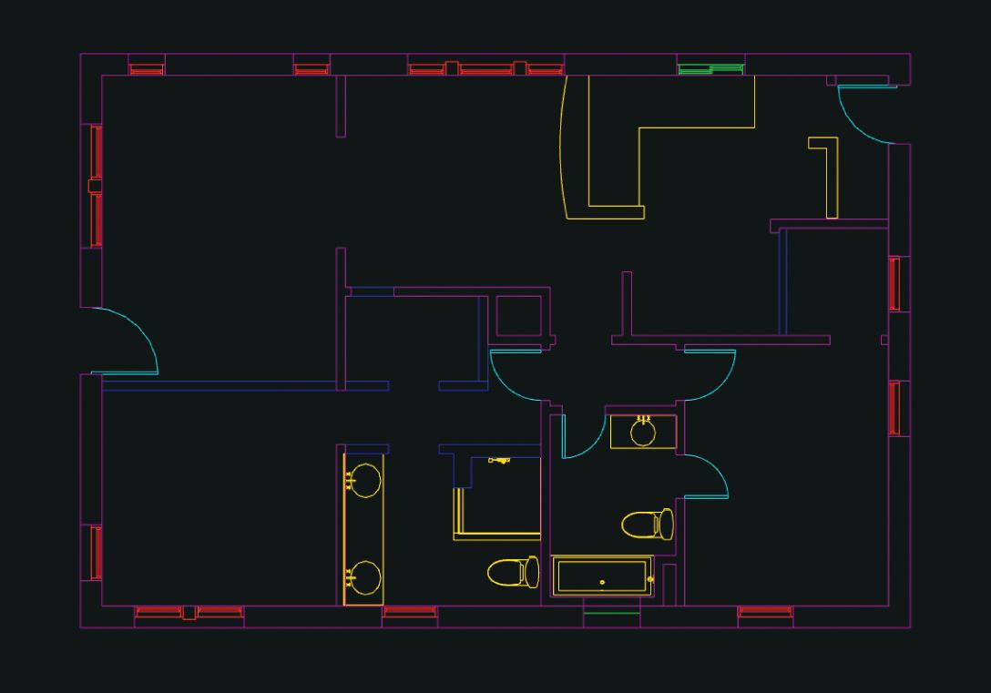
Using the DWG Exports
Once all of the exports are completed, they can be compiled into a single CAD drawing to create any type of plan needed (Figure 18.13). Ideally, you will email all of these background .dwg files to consultants, or host them for download on a server. Then, the consultants can insert the drawings into their CAD program however they like. When you update the design, re-export the backgrounds and then just send a message to the consultants so they know to download and overwrite their files. This method is by far the most efficient way to keep everyone on the same page, but it requires all consultants to be proficient in 2D CAD.
For consultants who don’t really know how to use CAD this way, you might find it easier to just do it for them. Simply reference the DWG exports into your favorite CAD program to create a series of drawings for them. Be sure to maintain the drawing origin for each reference, to insure that all drawings stack right into place. At this point, assign line weights to each of the external references as a whole.
TIP if you don’t have a cAD program to compile the drawings, you can import all the drawings into SketchUp as .dwg files, and then export the entire file as a 3D .dwg.
You can also use the 2D export to abandon ship, and then finish the documentation in your favorite 2D CAD program. Reference the files in the same, and then you can explode, redraw, and modify your file at will. Keep in mind that when you export 2D CAD snapshots, there is no connectivity between the components—they do not become blocks. These DWGs are basically exploded, simple linework and might require some rebuilding and redrawing.
c h APT er Poin TS
☑ For an extensive collection of building model organization diagrams (MODs , scene organization diagrams (SODs), and their corresponding SketchUp models, visit www.suexch.com.
☑ While you’re brainstorming in SketchUp, use the tools loosely and freely. Keep in mind that there are built-in ways to tighten up the dimensions and keep the geometry organized, even in a concept model.
☑ When moving a concept to a precise model, it is usually best to start a fresh model. Use Paste in Place to pull useful pieces of the concept model into the precise model.
☑ Typically, it is best to use precise dimensions and modeling techniques right from the beginning. Once you get the hang of the model organization and tool operations, it takes just as much effort to create a sketchy model as it does a precise model.
☑ A cloud file storage solution comes in really handy when you’re distributing lots of large files to consultants.


