
31 minute read
Chapter 19 Design Development Rendering


During the Design Development phase, it is often necessary to present a refined design in 3D. By doing this, you will enable the client to fully understand the design and sign off so you can quickly move on to the Construction Documents phase. Throughout the architectural design process, you will still use the modeling and organization techniques from the previous chapters, but in this chapter you’ll focus on presentation. You’ll learn how to create beautiful SketchUp animations and renderings, prepare your model for photorealistic rendering, and explore your photorealistic rendering options.
Po PU l AT ing A Scene
Advertisement
Any image you create will ultimately be used to sell an idea. Your design image should evoke excitement and the desire to be a participant in the image. You should put as much thought into populating your renderings as a realtor puts into staging a house for sale. Breathe life into the space by adding decorative objects, people, and action. Keep the following tips in mind when you’re populating a scene.
☑ Address your audience. Who are you selling this design to, and what will get them excited about the space? Now is a good time to think back to your first meetings when the client expressed their main desires. If they expressed a strong desire for a fireplace, show the fireplace glowing with a family gathered around.
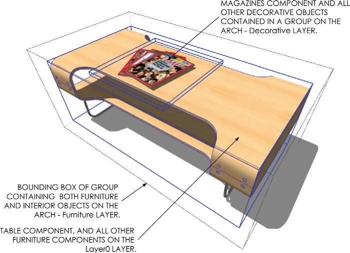
☑ Add decorative objects within the ARCH - Furniture container (Figure 19.1, Figure 19.2). Tables without food, magazines, or other details are boring. Such details are the objects that make a scene realistic; however, you don’t want them to render in the furniture plan.
☑ Download professionally modeled and textured components at www.FormFonts.com .
☑ Use custom textures from Google image searches or from FormFonts. See Chapter 7, “SketchUp Collections.”

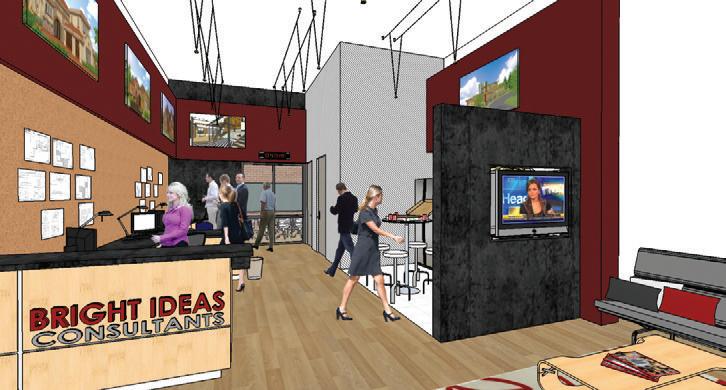
☑ To sell the experience, populate models with people participating in appropriate activities. Add them to the SITE – Entourage container. For winter scenes, use people in jackets. At a restaurant, mix casually and professionally dressed people. For an office, add activity such as presentations and collaborative group discussions. Perform a Google search for office and investigate what a real office looks like. Take note of the clutter that can add realism to an image, then apply those subtle nuances when staging your scenes. (Figure 19.3, Figure 19.4).
r en D ering in Ske T chU P
SketchUp renderings are traditionally “sketchy.” Utilizing the loose lines and cartoonish materials available in SketchUp conveys design intent in a way that is much softer than a sharp photorealistic rendering.
choosing an Appropriate Style
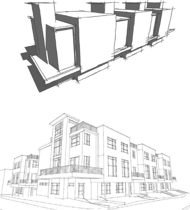
A style will drastically affect the way in which your audience receives your SketchUp rendering. If your design is still in a loose schematic state, present it with a sketchy style to remove some of the details you haven’t thought out. If your design is fairly complete and advanced, use a hard-line style rather than a sketchy style to insure the details are clearly represented. See Figure 19.5, Figure 19.6, and Figure 19.7.
Figure 19.5 A sketchy style rendered in Hidden Line mode leaves much of the detail to the viewer’s imagination or presenter’s explanation, which is great for designs that are still in schematics. If you haven’t addressed the materials, don't show them.
creating Scenes
After you determine the style you want to use, you can create the scene.


1. Navigate to a desired view, and then select an appropriate style from the Style browser. You might want to click on the PRESENTATION utility scene tab and use the final PRESENTATION style that was created in Chapter 5, “The Professional’s SketchUp Template.”
TIP Use the Advanced camera tools and Position camera tools to place yourself in the model accurately, set the eye height, etc.
2. To add a new scene, click on the plus sign (+) at the top-right corner of the Scenes dialog.
3. Using the LO_ format, rename the scene LO_Perspective 01. Check on all of the Properties to Save.
4. Repeat to create additional scenes.
e xporting images from SketchUp
The easiest way to produce an image is to use the Export 2D Graphic command in SketchUp. This creates a 2D snapshot of the screen in several formats, including raster and vector.
1. Click on the Scene tab that you would like to export.
2. Click on the File drop-down and select Export 2D Graphic.
3. Set the Export Type to .jpg if you plan to print or email the rendering as is. This is one of the most common raster-image formats. If you plan to perform a lot of postprocessing, consider exporting the scene as a .tiff file.
4. Click on the Options button to set the image resolution as shown in Figure 19.8.

E Xporting Images From Layout
Exporting images from LayOut is a very efficient way to export multiple views from SketchUp, and it allows you to leverage all of LayOut’s professional export settings.
Adding Pages
Add a page within your LayOut presentation for each perspective rendering scene you created in SketchUp. Just follow these steps:
1. Within LayOut, start a new file using the BIC_8.5x11 – Landscape template. Save this file to your TEMP folder or an appropriate project folder and name the file BIC_Row House – Renderings.layout.
2. Click on the File drop-down and choose Insert. Navigate to the BIC_Denver Row House.skp model in the chapter files folder, select it, and click the Open button.

3. Click and drag on the edge of a viewport to loosely resize the viewport. Once you let go, immediately enter new viewport dimensions: 11 g, 8.5 g , then press Enter (Figure 19.9).
4. Center on the page horizontally and vertically. To do that, use the Custom Arrange toolbar, or right-click on the viewport and select Center c Horizontally on Page and repeat for Center c Vertically on Page.
5. Select the viewport, and then assign the LO_Perspective 01 scene, rendering type, and line weight in the SketchUp Model Inspector.
6. Duplicate the page and repeat the process for every desired scene.
Exporting Multiple Images
Although it is usually best to export a .pdf file, sometimes you’ll want to export a series of images for post-processing in an image editor. Follow these steps to batch export raster images from LayOut.
1. Click on the File drop-down and choose Export c Images.
2. Navigate to the appropriate project folder, assign an appropriate name, choose a .jpg or .png export, and click on Save.
3. In the Image Export Options dialog, which is automatically launched, choose which LayOut presentation pages will be exported as well as the image resolution (Figure 19.10). Typically, 300 pixels/inch is an acceptable highresolution export for print, and 72 pixels/inch is an acceptable resolution for screen presentations, such as a website.

TIP it is okay to keep your large-format renderings in a separate layout presentation from your drawings. you can link one SketchUp model to as many layout presentations as you like.
creating Animations
SketchUp animations are easy to create, and they provide an excellent way to explore a 3D space without having the model open and rendering in real time.
Creating an Animation Model
To create an animation file, follow these steps:
1. Within SketchUp, click on the File drop-down and select New to start a new model.
2. Click on the File drop-down and choose Import. Verify that the Files of Type dropdown menu is set to SketchUp Files (*.skp).
Inserting one SketchUp model into another creates a link between the instance and the referenced model. This technique will limit the number of scenes and Scene tabs in the proposed conditions model. When you make changes to the original BIC_ Denver Row House.skp model, you can just right-click on the reference in the Animation file and select Reload to see the updated model.
3. Navigate to and select the BIC_Denver Row House.skp file. Click the Open button to import the model.
4. Save the file as BIC_Denver Row House – Animation.skp.
Adding Scenes
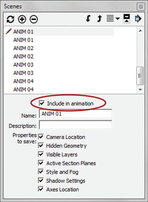
SketchUp animations are scene based. This means that SketchUp will link together all of the scenes in the animation into one movie. Be sure to check on all of the properties to save and choose which scenes should be included in the animation (Figure 19.11). Typically, every scene you create in the animation file will be included in the animation.
1. In the Scenes browser, click the Add New Scene button to create a new scene.
2. Name the scenes based on segments. For example, each scene in the first stream of animation should be titled 01.
3. Click on the Window drop-down and choose Model Info. Click on the Animations tab.
4. Check on the Scene Transitions and adjust the amount of time between scenes based on personal preference. Typically, you should leave the Scene Delay set to 0 for a more fluid animation.
Exporting Animations
To export your animation, follow these steps:
1. Click on the File drop-down and choose Export c Animation.
2. Click the Options button at the bottomleft corner of the Export Animation dialog (Figure 19.12).

3. Navigate to your TEMP folder or an appropriate project folder, and select Export.
Animation Tips
Keep the following tips in mind when you’re creating animations in SketchUp.
☑ Add a sky dome to the animation file to create a more realistic sky effect. Search the 3D warehouse for sky dome (Figure 19.13).
☑ Use ruby scripts to make your animations smoother. Visit www.smustard.com to purchase and experiment with Flight Path, Page Smoother, TimeEdit, and PageDelayEdit.
☑ The dimensions for high definition 1080p are 1920 pixels wide by 1080 pixels high. Thin out lines by exporting at a higher resolution, such as 3840 n 2160, and then crunching the file down in a video editor.
☑ Each instance of SketchUp utilizes one core. Therefore, if you have a quad-core system, you could maximize your machine by opening four instances of SketchUp and rendering the animation in four separate segments, and then compiling the segments in a video editor. To do this, you would need one animation file with all of the scenes set up. Every time you opened the animation file, you would need to uncheck different scenes to include in the animation.
☑ With more time between scene transitions, the camera will appear to fly slower.

☑ A higher frame rate will allow you to slow down an animation in a video editor without deteriorating the quality.
☑ By using simple video editing programs such as Windows Movie Maker or iMovie, you can add a lot to your animations. For example, you can add captions, fade effects, and chop out the “bouncing” effect often present in scene based animations.
☑ Sketchy styles do not typically render well in animations.
Pho T ore A li ST ic r en D ering
Once a design has reached a level of detail that resembles a real space, it is best to render it as a photorealistic image. Photorealistic renderings make typical “cartoony” SketchUp renderings look real by adding soft shadows, reflections, light sources, and other natural properties of light.

TIP if a design is incomplete and isn’t populated, your photorealistic rendering will look amateurish.
In the not-so-distant past, photorealistic rendering was a huge task involving exporting to expensive software packages that only Hollywood studios could afford and only Hollywood special effects wizards knew how to use. Today, photorealistic rendering can be accomplished in SketchUp. Most rendering plugins are extremely inexpensive, and they produce beautiful images that rival professional stand-alone rendering software (Figure 19.14, Figure 19.15).
Preparing a Model
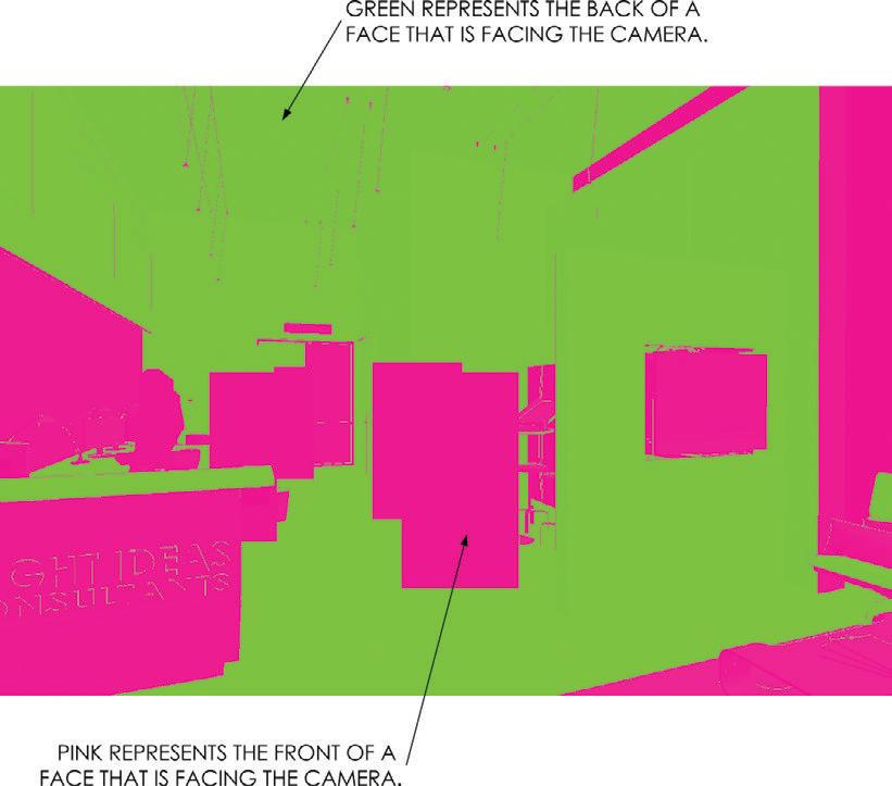
Photorealistic rendering is a breeze with many of the available plugins for SketchUp, but you should first optimize the model for rendering using the Orient Faces utility scene (Figure 19.16). This utility scene displays the geometry in your model based on which side of the surface is facing you. The front is pink and the backs are green. Rendering the front of faces will produce more predictable results.
1. Click on the Orient Faces utility scene tab.
2. Double-click into Groups and Components, and then right-click on a green face and choose Reverse Faces to change it to pink. You can select multiple faces, right-click on the selection, and choose Reverse Faces to change more than one face at a time.
3. Click on the Design utility tab to verify that the correct material is applied to the surface. Usually, after reversing a face, you will need to apply a material to the front that was previously hidden.
4. Reverse the rest of the faces until all of them are pink.
Figure 19.16 The Orient Faces utility scene makes it easy to identify the front and back of faces. Typically, your results will be more consistent when your render the fronts of surfaces.
Photorealistic rendering Programs
Listed are several options for rendering inside SketchUp. Each program or plugin has its own unique features and benefits.
☑ Twilight Render: http://twilightrender.com/
☑ Shaderlight: http://www.artvps.com/
☑ Podium: http://suplugins.com/
☑ Render Plus: http://www.renderplus.com/wp2/
☑ Indigo Renderer: http://www.indigorenderer.com/sketchup
☑ Renditioner Pro: http://www.imsidesign.com/Products/Renditioner/tabid/1756/
Default.aspx
☑ RenderPlus: http://www.renderplus.com/wp2/wk/IRender_nXt.php
☑ LumenRT: http://www.lumenrt.com/
☑ RenderIn: http://www.renderin.com/
☑ LightUp: http://www.light-up.co.uk/
☑ Vray: http://www.chaosgroup.com/en/2/vrayforsketchup.html
☑ Maxwell for SketchUp: http://www.maxwellrender.com/index.php/maxwell_for_sketchup
☑ Caravaggio: http://www.caravaggio3D.com/
☑ Lumion: http://www.lumion3d.com/
Post-Processing
It is always a good idea to run your final images through an image processor to fine-tune the brightness, contrast, color balance, etc. GIMP and Adobe Photoshop are powerful image editors that you install locally on your computer. There are also several image editors that can accomplish many of the same tasks for less money. Several cloud-based image editors are listed here:
☑ http://www.photoshop.com/tools
☑ http://www.splashup.com/
☑ http://pixlr.com/
☑ http://www.picmonkey.com/
☑ http://www.sumopaint.com/app/
c h APT er Poin TS
☑ Populate your scenes to sell your idea. Make the viewer want to participate in the image.
☑ To minimize cost and exports while maximizing efficiency and connectivity, pick a photorealistic renderer that works inside SketchUp.
☑ Use an image editor to fine-tune the final output.
Chapter 20
Construction Documents
During the CD phase, you (or the designer) will document all of the final design decisions and compile them into a set of construction documents. These documents are the culmination of The SketchUp Workflow for Architecture, and they are where all of your hard work and organization really pay off. In this section, you will see that you can create construction documents in LayOut and that the process is actually very efficient .
c r U ci A l c once PTS for Doc UM en TAT ion
Before you create the construction documents, you should understand some basic concepts that will help you create your drawings quickly and efficiently.
Section Planes
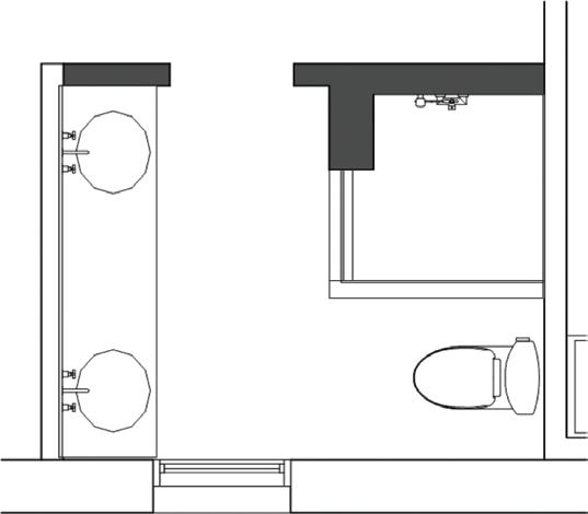
Section planes are the key to describing 3D spaces in 2D diagrams. Most people think section planes are just used for building sections; but really, any plan is also created using a section plane, placed horizontally (Figure 20.1).
Horizontal section planes can be placed at the main level of the model or in an ARCH container if needed. One reason for placing the section plane in an ARCH container is to cut different entities at different heights. Multiple section planes allow you to control which entities are being cut at what height (Figure 20.2). For instance, you might want the exterior walls to be cut at a different height than the interior walls. In such case, you could add several section planes within the ARCH containers to cut everything exactly as needed.

Section planes are separated by containers. In other words, a section plane within a group affects only the geometry in that group. This means that you can have multiple active section planes per scene , as long as each active section plane is in a separate container..

TIP keep in mind that you can reuse the same section plane for multiple plan views.
Vertical section planes are typically placed on the outside of the model, at the base level, because everything is cut at the same time for elevations and sections.
Stacking Viewports to control line Weights
The ability to completely control line weights in your drafting software is critical to any drafting workflow. To completely control line weights in LayOut, you will need to master the concept of stacking viewports.
Each plan drawing in your set of construction documents is composed of one or more viewports. Each viewport is linked to a plan scene within SketchUp. Each plan scene within SketchUp represents an array of line weights. This means that you will typically create one scene for “heavy” line weights (walls and floors) and one scene for “light” line weights (doors, windows, furniture, etc.).

To do this, you will need to actually stack the viewports in LayOut. Each viewport can have a line weight applied to it.
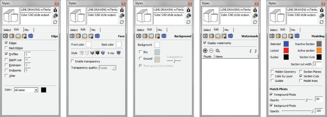
Each scene represented in LayOut has an array of line weights. (See the “Line Weight Theory” section in Chapter 10, “The LayOut Interface.”) You apply a line weight to the viewport, and the style will translate that line weight into an array based on the profile and section cut settings. Figure 20.3 illustrates why it is best to assign line weights of .2 and .6. As you can see in the figure, these settings provide the largest array of line weights.
There is really no limit to the number of viewports you could stack; however, to keep your presentation and number of scenes manageable, two is usually enough, and three or more are necessary only if you need several different hatches.
All viewports that compose a drawing belong on the DRAWINGS layer in LayOut. You could use layers to control the stacking order, but then you would have a lot more layers to manage in LayOut. An easier way to manage the stacking order is to send the viewport backward and forward. Use either the Arrange toolbar, or right-click on a viewport and select Arrange c Send Backward/Forward to manage the stacking order, or sublevels of the layer.
The suggested stacking order and rendering settings of viewports is as follows:
☑ Light line weight on top, rendered as a hybrid (.2 line weight)
☑ Heavy line weight below, rendered as a vector (.6 line weight)
☑ Any hatching on the very bottom, rendered as a vector (line weight n/a)
TIP There is no need to insert the SketchUp model multiple times to create multiple stacked viewports. you can copy and paste the viewport right on top of the copied viewport. you can also use the Duplicate command available in the edit drop-down menu to duplicate a selected viewport. Then hold down the Shift key and use the arrow keys to nudge the new viewport four times up and four times to the left so that it is once again aligned.
Hatching
Through the creative use of styles, or simply by drawing the hatch in LayOut, you can add hatching to your LayOut drawings. Each hatch method has its own limitations and requirements regarding efficiency and rendering settings. Before you incorporate hatching, explore all the options and then apply the best strategy for your particular design and set of drawings.
SketchUp Hatch
Using SketchUp to create the hatch provides a dynamically linked hatch in LayOut. This means that if you move a wall, the wall lines and hatch will update simultaneously in all the LayOut drawings. This method is ideal because it eliminates the need to redraw hatches as your design evolves.
A limitation to this method is that you can use only vector fills, and not the patterns or materials that most CAD users have come to expect. The good news is that if you are printing in color, you can use color fills.
If you are printing in black and white, you can create a nice array of fills with grays 10 to 25 percent apart. However, you will need to be selective with the amount of hatching you use in this way because each hatch requires its own viewport, which further complicates the stacking of viewports.
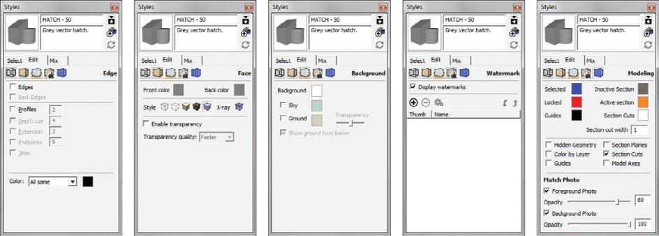
Create the Hatch – 50 (Figure 20.4) style now, and you can use it later when you create drawings composed of several stacked viewports. You can also create other hatch styles, such as HATCH – 25 and HATCH – 75 by adjusting the HLS lightness slider within the Style Edit tab.

LayOut Hatch
Another hatching method is to use the Drafting tools in LayOut to create a solid vector fill (Figure 20.5). To do that, activate any of the Drawing tools, set the fill to the desired “hatch color,” and turn off the stroke. Add LayOut shapes or lines with fill to define special hatched areas. Be sure to right-click on the fill and select Arrange c Send to Back so that the lines will be on top.
You could also use the fill you just created as a clipping mask for a hatch image or a .skp hatch file. To do that, create a repeating pattern in an image editor or in SketchUp and use the fill as a clipping mask (Figure 20.6).
The major downside to creating hatches in LayOut is that there is no dynamic link between the hatch and the drawing. If you update the plan, you will need to be aware of any conflicts created with the hatching. The benefit of this method is that you will be able to add as much hatching as you like with any pattern you need. Typically, this technique is best utilized for smaller areas of hatching.
TIP right-click on any hatch and choose Send to Back. All hatches sit at the bottom of the stack on the DrAWingS layer.
Conceptual Layers
CONCEPTUAL layers are typically used as adjectives that explain the ARCH and SITE containers, but they can also help you achieve a desired look. As you saw in previous chapters, anything that does not render correctly in 3D can be corrected with a 2D graphic by using the CONC – 2D Graphic and CONC – 3D Object layers. In this section you will see how The CONC – Always Off and CONC – Details layers help you eliminate unneeded lines and excessive detail while maintaining model organization and efficiency.
CONC – Always Off
Because of the way SketchUp works as a surface modeler, there will be times when you don’t want to see an edge but you won’t be able delete it because it is needed to complete a surface. This often happens when containers meet—for example, at new and existing walls, between levels, and where exterior meets interior.

One option that will solve this problem is to hide the edge, but hiding is more of a modeling tool than a permanent fix. If you never want to see a specific entity, assign it to the CONC – Always Off layer, which is always turned off (Figure 20.7).
Refer to the following images in Figure 20.7:
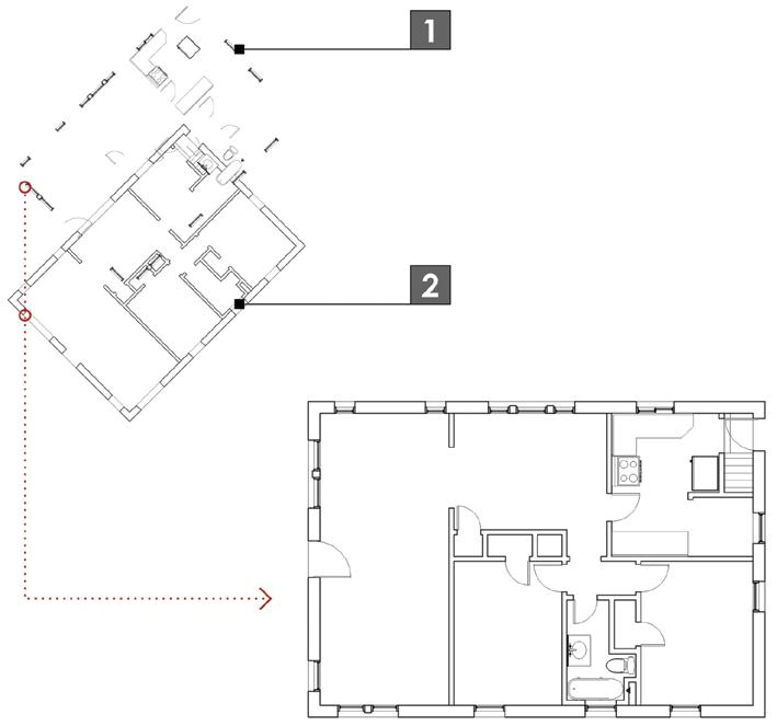
1. Notice that where the door was demolished and the new wall container meets the existing wall container, there are still lines. These lines need to remain in the model to make the surfaces, but they shouldn’t be seen.
2. Double-click all the way into the existing wall’s container and select the edges as shown. Assign them to the CONC – Always Off layer. The edges are not gone yet because they also exist in the new wall’s container.
3. Double-click all the way into the new wall’s container and select the edges as shown. Assign them to the CONC – Always Off layer.
4. The wall appears seamless now, as it should for perspective renderings and elevations.
5. Switch to the SCOPE utility scene, and note that both the new and existing functionality are maintained.
TIP remember the “All edges and surfaces are drawn on layer0” rule discussed in chapter 4, “SketchUp Basics”? The conc – Always off layer is the one exception to that rule, although this layer is not limited to edges.

CONC – Detail
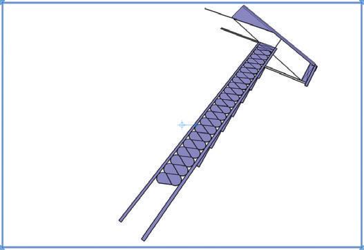
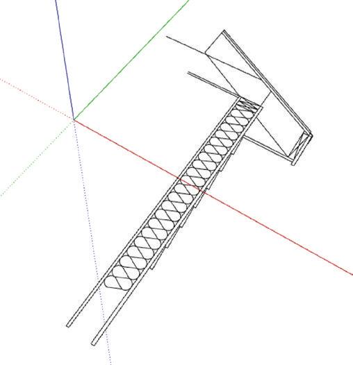
The CONC – Details layer helps you increase or decrease the level of detail shown for an object. There are often details associated with 3D objects that don’t render properly in plan, so you need this layer “switch” to control the amount of detail shown. The entities placed on the CONC - Details layer are desirable in 3D views and elevations, but not in plan (Figure 20.8). Think of stair railings, door hardware, and window fenestrations (Figure 20.9).
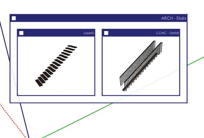
Figure 20.8 Some details of objects and architectural features do not render properly in plan, but are needed for a convincing elevation or 3D perspective view. Such entities belong on the CONC – Detail layer.
Figure 20.9 In this MOD, the stairs where the railings and main support are placed on the CONC – Detail layer. This will allow the stairs to render correctly when shown in plan.

Dr AW ing S
Every drawing is composed of a scene, or combination of several scenes with varying styles, all combined and carefully stacked within LayOut. The following instructions explain how to make many common drawings that are needed to describe a building.
Plans
Each plan drawing is created by stacking two or more viewports on top of each other. Use the scene organization diagrams (SODs) to create the necessary scenes in SketchUp. Next, assign the scenes to viewports in LayOut and stack the plans as shown to create each plan drawing. While you’re building these plans, keep in mind the following:
☑ All of the plans should share the same camera location, with the top-down view set to parallel projection.
☑ It is okay for several floorplan scenes to share the same section plane.
☑ Typically, the section plane for a plan should be approximately 4 f off the finished floor.
☑ Each viewport will be set to a scale appropriate for the plan. Assume that all plans, elevations, and sections for the model will be set to 1/8 g = 1 f-0 g, and enlarged plans will be set to 1/4 g = 1 f-0 g .
TIP This is a complicated process with a lot of steps represented by the Scene organization Diagrams and Viewport Stacking Diagrams. your first time through might be a little frustrating. now would be a good time to visit www.suexch.com and watch the video tutorial on how to create these drawings, then use the book as a guide as you make the drawings yourself.
Existing Conditions Plan
The existing conditions plan represents the structure as it stands, before you make any changes (Figure 20.10). You will be using only the BIC_3458 Steele St – Existing Conditions.skp model for this drawing. This is the simplest plan drawing to create because it uses one model and only has two stacked viewports (Figure 20.11).
Demolition Plan
The demolition plan represents the pieces of the structure that will remain, as well as the pieces that will be removed (Figure 20.12). The demolition plan (Figure 20.13) utilizes the existing conditions model combined with the proposed conditions model.
Walls and entities to be removed are represented by dashed lines in this plan (Figure 20.14). To show the existing conditions dashed, you must first explode the existing conditions viewports. Although this removes the dynamic link between the SketchUp model and the viewport, it is okay because, technically, the existing conditions model is complete and will never change.


Construction Plan

The construction plan describes what is to be built (Figure 20.15). New walls are delineated through the use of a hatch fill (Figure 20.16).

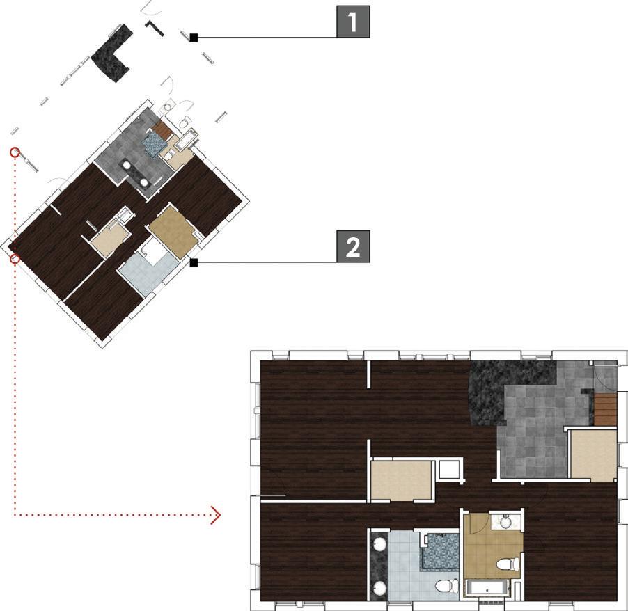
Finish Plan

The finish plan describes the materials that will be used to finish the space (Figure 20.17). You can use the standard LINE DRAWING style to create a black-and-white finish plan, or you can create a new LINE DRAWING style (Figure 20.18) that also shows colors and textures (Figure 20.19).
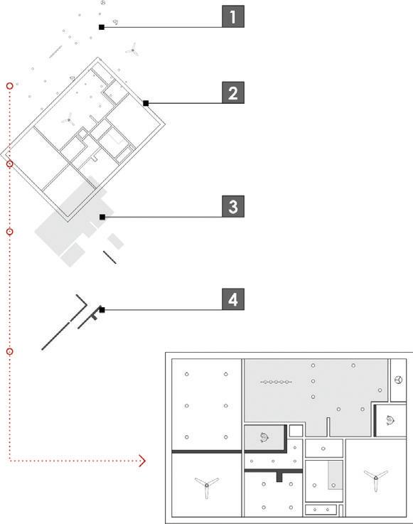
Reflected Ceiling Plan
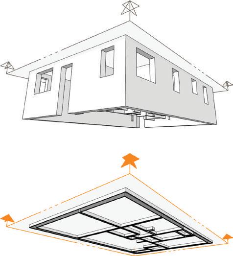
A reflected ceiling plan describes what will be built on the ceiling of the space (Figure 20.20). Imagine looking down on a plan, through the ceiling, from above, and the floor is a mirror. What you would see is a reflected ceiling plan (Figure 20.21). This plan is very diagrammatic in nature, so creating it can be a little tricky.
Add the section plane above the window and door headers, but below the ceiling (Figure 20.22). Set the view from the bottom as a parallel projection, similar to a plan. Once you insert the drawing into LayOut, right-click on the viewport and choose Flip c Left to Right. This will make the reflected ceiling plan drawing read the same as the other plans.

Enlarged Plans
Sometimes you need a bigger plan to further explain a complex space and make room for cramped annotations and dimensions. To create a bigger plan, use the same methods you used for creating any plan—just use a larger scale (Figure 20.23).
Sections and elevations
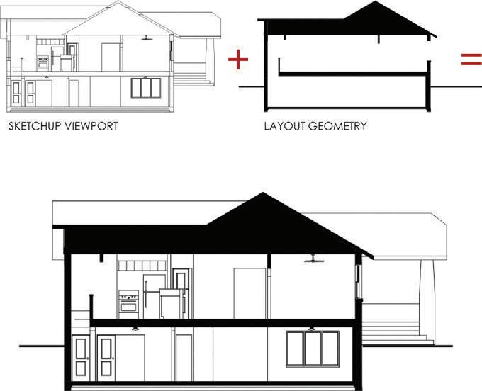
Creating section drawings and elevation drawings is much easier in that they only require one viewport. The downside is that you’ll need to complete many of the graphics in LayOut. This will essentially break the dynamic link because you will need to update the LayOut geometry if you update the section drawing.
To learn how to create sections and elevations, you will use a more complex and developed model, BIC_3458 Steele St – FINAL.skp, that includes multiple levels. Typically, a section or elevation section plane will exist at the base level of the model, outside of any container.
Building Sections
Building sections describe the relationship between the levels of a structure, and they provide interior elevation information. Keep these other tips in mind when you create section drawings:
☑ Place the building section plane at the base level of the model (Figure 20.24).
☑ Right-click on a section plane and choose Align View to set the camera view perpendicular to the section plane.
☑ Within SketchUp, right-click on a section plane and choose Create Group from Slice. Then, cut the group of linework and paste it into LayOut. Render it as a vector and explode. Now all of the linework for the section is readily available—but keep in mind, it is not dynamically linked to the section.
☑ Use the Line Drawing style to create a black-and-white drawing, or use the LINE DRAWING w/Textures style to create a color section.
☑ Use the Drawing tools in LayOut to create fills and accentuate the 2D SketchUp drawings to give them more visual pop (Figure 20.25).
Exterior Elevations
Exterior elevations convey materials and vertical heights. Elevations are possibly the simplest drawings to create because frequently they do not require any section planes and there is only one viewport. Keep the following tips in mind when you’re creating exterior elevations.
☑ Right-click on a surface on the elevation that you are creating and choose Align View to set the camera perpendicular to the selected face. This technique is especially helpful when aligning the camera view with an angled wall.
☑ In SketchUp, use section planes to peel away unwanted portions of the site.
☑ In SketchUp, use fog to provide a sense of depth.
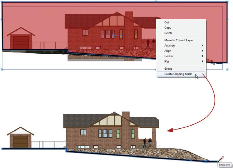
☑ In LayOut, use a clipping mask to remove unwanted portions of the site (Figure 20.26).
☑ You can get trees from 3D trees in SketchUp or from the pre-loaded 2D tree scrapbook collections in LayOut.
☑ Use the LINE DRAWING w/Textures style to make a color elevation, depending on the type of project and printing you are doing.
TIP Any layout entity that complements the drawing, such as a hatch or ground line, belongs on the DrAWingS layer.
Interior Elevations
Interior elevations are typically drawn at a larger scale than building sections, and they describe vertical dimensions and finishes. Keep the following tips in mind when you’re creating interior elevations.
☑ Start by using a building section scene in SketchUp, or even using an existing building section scene.

☑ Turn off layers and hide as much geometry as possible in SketchUp. LayOut will process all the geometry that is turned on, even if it is not shown in your viewport.
☑ Apply a clipping mask in LayOut to isolate the desired portion of the drawing (Figure 20.27).
☑ Use the Line Drawing style to create a black-and-white drawing, or use the LINE DRAWING w/Textures style to create a color interior elevation.
☑ Use the Drawing tools in LayOut to create fills. This will give your drawing more pop.
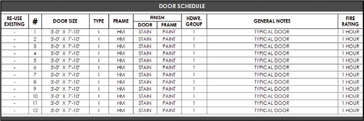
Schedules
Schedules are used to convey the quantities you’ll need of products, such as doors, windows, and finishes (Figure 20.28). A schedule in LayOut is actually very simple, created mostly of text boxes with different fills, strokes, fonts, and text sizes (Figure 20.29). Keep the following tips in mind when you’re creating schedules in LayOut.
☑ There is no dynamic link to the entities you are scheduling, so make sure you count carefully. It is usually easier to catch schedule mistakes when the schedule and drawings are printed.
☑ Once you build a schedule, add it to a scrapbook collection for use on other projects.
☑ Use the Drawing tools in LayOut to complement complex schedules.

Details
A detail explains the finite construction of a specific building condition. When you’re creating details in any drafting program, there is a disconnect between the dynamically linked design model and the detail drawings. It would be nearly impossible to build a model with the level of detail and organization necessary to show all levels of detail at any architectural scale. Because of this, it is okay to “detach” your details from the design model.
Draft the details in 3D SketchUp just as you would in 2D CAD (Figure 20.30). Use SketchUp’s ground plane as your digital drafting table. Consider using a separate SketchUp model, or even a “throwaway model,” when you’re creating details.

Once you have finished drafting the detail, select all of the lines, and then cut the lines out of SketchUp. Paste the lines into LayOut to insert them as a linked SketchUp model (Figure 20.31).
With the viewport still selected, use the SketchUp Model Inspector to set the viewport to Top View, Ortho, Vector Rendering, and choose an appropriate scale for a detail drawing, such as 1 g = 1 f-0 g (Figure 20.32).
Explode the viewport so that you can control the line weights. Once it’s exploded, you will probably need to ungroup several LayOut groups. To do that, right-click on the group and select Ungroup. Then, use LayOut’s Drawing and Modification tools in conjunction with the Shape Style Inspector to complete the detail drawing (Figure 20.33).
SketchUp is a 3D program, so there is no reason you shouldn’t branch out and create 3D details. Often 3D details can do a better job explaining conditions than 2D can. As a starting point, try searching the 3D Warehouse for Construction Details (Figure 20.34).

TIP Save all of your details in the Scrapbooks library so you can use them on other projects. frequently, a typical project type uses standardized details, and you can save a significant amount of time by building a collection of details.

Anno TAT ion S
Annotations are the extra layer of information that further describe the drawings. Annotations complement the graphic with accurate dimensions and precise descriptions. Keep these tips in mind when you annotate your drawings:
☑ Because it is difficult to draw accurate column lines in LayOut, draw them in SketchUp. Treat column lines as 2D Graphics that compliment a 3D object of a beam.
☑ Door and window center lines are drawn in LayOut
☑ Be sure to switch to the ANNOTATIONS layer, which should be active most of the time.
☑ It is okay to link your model to several different layout files to break up the set. This will reduce rendering time and allow you to distribute work among the team.
☑ When you’re dimensioning, typically it is best to turn off Auto Scale and set the Dimension Scale manually in the drop-down menu. This will eliminate potential errors from snapping to a point outside of a viewport.
☑ If you find yourself using the same annotation, take the time to add it to your scrapbooks.
c h APT er Poin TS
☑ Leverage conceptual layers to achieve a desired look and level of detail within your drawings.
☑ You can download professionally built title blocks and scrapbooks at www.suexch.com , as well as review extended content regarding the creation of construction documents with SketchUp Pro and LayOut.
☑ Any drawing can be exploded to provide you with complete line-weight control in LayOut.
Index
2D graphic, 225
3D object, 335
A acronym, identifying, 33–34 add hidden layer plugin, 146 add location, 263–265 animation, 350–353 exporting, 351–352 scenes, 351 tips, 352–353 annotation tools, LayOut, 214–220 dimensions tool, 217–218 label tool, 216–217 text tool, 214–216 annotation, LayOut 283–284 arc tool, 62–64 architectural scale, 173–174, 309–310
Archiving, 45–48
ARCHIVE folder, 37, 47 closing a project, 47 organizing, 46–47 project ARCHIVE folder, 39–40, 46 re-opening an archived project, 48 strategy, 45–46 arcs, LayOut
2-point arc tool, 210–211
3-point arc tool, 211–212 arc tool, 210 pie tool, 211–212 array, linear, see move tool array, polar, see rotate tool as-built drawings, 305–327 auto-render, 172, 181, 195–196 axes, move, 121 B background drawings, see consultants Bezier Spline Tool, 144 BIM, 20–29 common features of, 21 explanation of, 20–21
SketchUp and LayOut as, 22–28 advantages of, 22–27 disadvantages of, 28 extended functionality, 28–29 stages and uses of, 21 building context, 286 building information modeling, see BIM building section, see drawings
CAD exporting to 2D, 336–341 exporting to 3D, 335–336 modeling from existing, 326–327 callout, see scrapbooks, creating custom center lines, 379 circle tool
LayOut, 212
SketchUp, 58–60 circles and segments, 51, 58–60 clipping mask, 252–254 cloud storage, 45 colors inspector, 177 column lines, 379 components, 137–140 accessing collections, 139–140 component collections, 137 components browser, 137 finding, 138–139 organizing models with, see containers conceptual layers, 362–364 construction plan, see drawings
Consultants background drawings, 336–341 folder, 38, 40–41
Containers, 82–93 components, 84–85 explode, 93 groups, 82–83 modifying, 88–91 naming, 86–87 navigating, 86 nested, 91–92 overview, 82 context, see building context copy
LayOut, see select tool
SketchUp, see move tool core concepts, SketchUp, 51–53 creating geometry, 56 custom toolbars, LayOut 197–199
D
Dashed Lines ruby, 145 default material, 90–91 default settings, tool, 205 demolition, 329 demolition plan, see drawings detail, see drawings detail callout, 245–246 detail, level of, 333 diagrammatic utility scenes, 119–121 dialogs, SketchUp, 125–126 dimension style inspector, 185–186 dimension tools, LayOut angular, 218 linear, 217–218 dimensions
LayOut edit, 219–220 properties of, 219
SketchUp, 106 document setup general, 162 grid, 163–165 paper, 165–166 references, 166–168 units, 168–169 door tag, 236–237 drawing title, 241–242 drawing tools, LayOut, 205–213 drawing tools, 56–64 drawings detail, 377–378 elevation, exterior, 373–374 elevation, interior, 374–375 plans construction, 368 demolition, 365–367 enlarged, 372 existing conditions, 365 finish, 369–370 reflected ceiling, 370–371 schedule, 375–376 section, building, 372–373
DWG exporting to, see CAD modeling from existing, see CAD edge drawing tools, 60–64 edge, heal an, 62 edit linked, LayOut image, 255
SketchUp model, 254 text, 257 elevation, see drawings elevation levels, 284 ellipse tool, LayOut, 212–213 enlarged plan, see drawings entity info, 87 entourage, 345 eraser tool, LayOut, 225 existing conditions model, 319–326 explode
SketchUp, 93, 316
LayOut, 280 export
2D DWG, 336–341
3D DWG, 335–336 animation, 350–352 images
LayOut, 348–350
SketchUp, 348
PDF, 285 extensions, see ruby scripts existing conditions plan, see drawings exterior elevation, see drawings f field measurements importing, 315–317 modeling from, 319–326 preparing for, 305–306 recording, 312–315 scaling, 317–319 file management, see project organization file names, see project organization fill patterns, see hatch fill, 178 finish plan, see drawings flatten tool, 146 flip along, 90 folder management, see project organization folder names, see project organization follow me tool, 73–74 freehand tool, 64 g geo-location, 263–267 geo-modeling, 290–300 adding 3D detail, 296 importing 2D detail, 296–297 mass model, 291–292 match photo, 293–295 photographing a building, 290–291 tweaking textures, 298–300 getting started window, 160–161
Google Earth, 284 graphic scale, 239–240 grid, 163–165 align to, 311 custom, 311 groups, see containers h hatch
LayOut, 361–362
SketchUp, 360–361 hotkeys, see keyboard shortcuts hybrid rendering, 184, see also SketchUp model inspector image, import
LayOut, see insert
SketchUp, 296–297, 315–317 inferences, 53, 78–82 constrained on line, 80–81 introduction, 53 line intersect, 81–82 multiple points, 79 parallel to edge, 79–80
Insert, LayOut images, 254
SketchUp models, 250–252 text, 256 instant road plugin, 146, 268 instructor inspector, 190 interior elevation, see drawings interior elevation callout, 243–244 join tool, LayOut, 227 junk drawer, see MISC folder, see TEMP folder keyboard shortcuts
LayOut, 175, 196–197
SketchUp, 129–131 layer state utility scenes, 114–117 layer, ARCH – decorative objects, 344 layer, ARCH – furniture, 344 layer, CONC – 2D graphic, 334–335 layer, CONC – 3D object, 334–335 layer, CONC – always off, 362–363 layer, CONC – detail, 363–364 layers inspector, 188–189 layers
LayOut, 188–189, 233, 202–203
SketchUp, 95–96, 101, 109
LayOut benefits, 155–158 dynamic link, 154 paper space and model space, 152–153 what is LayOut, 149–152 line editing, LayOut, 224–225 line of symmetry, 90 line tool, 61–62 line weights, 182–183, 339–340 linear array, see move tool lines, LayOut, 205–208 curved, 207 edit, 224–225 freehand, 208 straight, 206–207 location of model, 266 locking axes, 61
M make unique, 85 mask, see clipping mask match photo, 293–295, see also geomodeling materials, 132–137 accessing material collections, 136–137 creating, 134–136 editing, 133–134 finding texture images, 134–135 materials browser, 133–134 measurements dialog, 55–56 measuring an existing building, see field measurements mental preparation, 10 mirror, see flip along
MISC folder, 38, 42–43
Model Info dialog, 105–109 animation, 105–106 credits, 106 dimensions, 106 rendering, 107 statistics, 302 text, 107 units, 108–109 model layering, 330–331, see also layers model organization, see containers model space, 152 modeling strategies, 331–332 modification tools
LayOut, 220–227
SketchUp, 56, 65–78 move tool
LayOut, see select tool
SketchUp, 67–71, 88 auto-fold, 72 linear copy and array, 69–71 precise move, 68 naming standards, see project organization navigating the 3D SketchUp environment, 54–55 navigating the 2D LayOut environment, 204 nearby buildings collection, 289–290 new construction, 329 north arrow, 239 outliner, 86–87, 325 overlapping edges, 52 P pages inspector, 187–188 palette, 246–248 pan tool
SketchUp, see navigating the 3D SketchUp environment
LayOut, see navigating the 2D LayOut environment paper space, 153 paste SketchUp model into LayOut, 308–309 PDF, export to, 285 photorealistic rendering, 353–356 post processing a, 356 preparing a model for, 354–355 plugins for, 355–356 plan, see drawings plugins, see ruby scripts poche, see hatch polar array, see rotate tool polygon tool oobjects, modeling, 333–335 offset Tool, 78 orbit tool, SketchUp, see navigating the 3D SketchUp environment organizing geometry, see containers
SketchUp, 58–60 LayOut, 213 populating a scene, 343–345 portfolio, 10–18 precise modeling, 332 preferences LayOut applications, 169–170, 194 backup, 170 folders, 171–172, 194–195 general, 172–173, 195–196 presentation, 173 scales, 173–174 shortcuts, 175, 197 startup, 176
SketchUp, 127–131
Drawing, 127
Files, 127–128
General, 128
Open GL, 129
Shortcuts, 129–131 prerequisites, 7–8 presentation utility scenes, 117–119
Project Organization, 35–37 naming standards files, 34–35 folders, 34 project folders, 38–44 standard folders, 35–37 proposed conditions model, 328–329 push/pull tool, 72–73 raster rendering, 183, see also SketchUp model inspector recover a document, 161 rectangle tool, 58 rectangles, LayOut, 208–209 bulged, 209 lozenged, 209 rounded, 209 reflected ceiling plan, see drawings remodel, 328 rendering
LayOut, 348–350
SketchUp, 347–348 rendering settings, 183–184 hybrid, 184 raster, 183 vector, 184 rendering quality, 201 reverse faces, 355–356 rotate tool, 74–76 polar copy and array, 75–76 rubies, see ruby scripts ruby scripts, 143–146 finding, 143 installing, 143–144 recommended, 144–146 using, 144 S save as scrapbook, 248 template
LayOut, 234
SketchUp, 122 scale and rotate multiple ruby script, 145 scale imported image, 317–319 scale tool, 76–77, 89–90 scale, architectural, 173–174, 309–310 scenes, 95, 99–102 creating, 114–121 dialog, 99 updating, 100–101 utility, 114–121
2D Drawing, 118
3D Perspective, 118
45, 120–121
90, 120–121
All Off, 116
All On, 115
Axis Check, 119
Design, 117
Exterior, 116
Interior, 116
Orient Faces, 120
Perspective, 118
Scope, 119–120
Site, 117 schedule, see drawings scope diagram, 330 scrapbooks inspector, 189–190 scrapbooks, 235–248 creating custom, 235–248 detail callout, 245–246 door tag, 236–237 drawing title, 241–242 graphic scale, 239–240 interior elevation callout, 243–244 north arrow, 239 palette, 246–248 section callout, 244 window tag, 237–238 save as scrapbook, 248 using, 248 scripts, see ruby scripts section, see drawings section callout, 244 section planes, 93–94, 357–359
Select tool
SketchUp, 65–67 modifying a selection, 66 selecting multiple entities, 65–66 right-click selection options, 67 window selection, 66
LayOut, 220–224 copying entities, 221–222 moving entities, 221–222 precise move and copy, 222 rotating entities, 223 scaling entities, 223–224 selecting, 221 shadow study, 301–303 shape style inspector, 178–179 sharing files, 45 shortcuts, see keyboard shortcuts site plan, 267–271, 274–275, 278–281 site section, 276–278, 282 site survey, digital, 261–285 site visit, preparing for , 305–306
SketchUp model inspector, 179–181
SketchUp comparison of free and pro, 8–9 future of, 31–32 sketchy modeling, 331–332 solar north, 266–267 split tool, LayOut, 226–227 stickiness of geometry, 52, 67–68, 82–83 stroke, 178 style tool, LayOut, 225–226 styles, 95, 97–98, 101–103, 110–114, 140–142 accessing collections, 141–142 choosing appropriate, 346–347 mix tab, 140–141 styles browser, 97–98 updating styles, 98
Utility, 110–114
Color by Axis Style, 112–113
Color by Face Style, 113
Color by Layer Style, 114
Design Style, 110–111
Line Drawing Style, 111 Presentation Style, 112 surface drawing tools, 57–60 surface modeler, 51 surface, heal a, 62 survey, topographic, 271–274, 284 symmetry, line of, 90 tag, see scrapbooks, creating custom
TEMP folder, 35, 48 template
LayOut, 229
SketchUp, 105 text style inspector, 186–187 text, LayOut properties of, 216, 232 text style inspector, 186 text tool, 214–216 texture images, see materials title block, custom LayOut, 230–234 toolbars
LayOut custom toolbars, 197–199 main toolbar, 161
SketchUp, 123–125 topographic survey, see survey, topographic trace building footprint, 307–308 roads, 267–268 trays, LayOut, 199–200
U Units
LayOut, 168–169
SketchUp, 108–109 update scene, 100–101 update style, 98 utility scenes, see scenes, utility
Vvector rendering, 184, see also SketchUp
Model inspector
Wwindow tag, 237–238 workflow, 4–5 zzoom tool
SketchUp, see navigating the 3D SketchUp environment
LayOut, see navigating the 2D LayOut environment
Zorro tool, 146


