
12 minute read
f


in D ing n e A r B y B U il D ing S
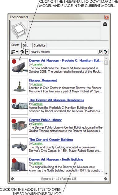
Instead of spending hours trying to measure and build your own context models, find someone else’s. Geo-located models uploaded to 3D Warehouse, as well as some buildings from Google Earth, are searchable and available for download through the Components browser. Once a location is attached to your model, you will be able to find other buildings that are close to your site in the Nearby Buildings collection. To do that, follow these steps:
Advertisement
1. To open the Components browser, click on the Window drop-down menu and choose Components.
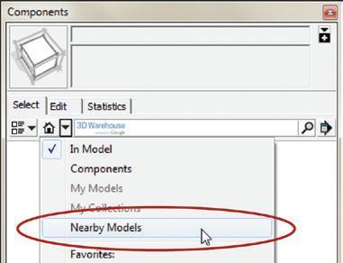
2. In the Components browser, click on the Collections drop-down menu and choose Nearby Buildings (Figure 16.4). Remember, this collection is available only after a model has been geo-located.
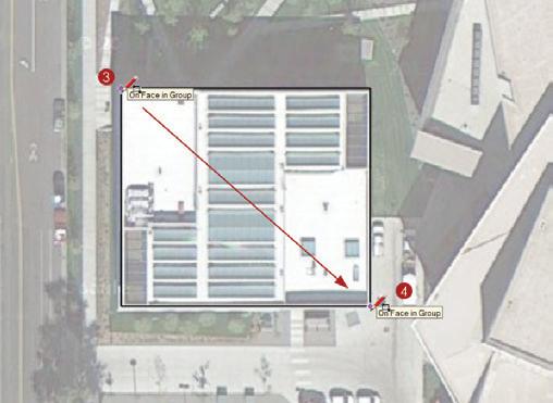
3. Click on the thumbnail icon to immediately download a model directly into the current SketchUp model. Find and import the models indicated with red dots in Figure 16.5.
4. Double-click on each of the context building models, click on the Edit drop-down menu, and choose Unhide c All. The lines you need to create a complete building-elevation line drawing will appear.
5. Unlock and delete the 3D terrain and aerial imagery in all of the imported context models. The most current and accurate terrain is already imported into your model (Figure 16.6).
TIP The nearby Buildings collection is very helpful for working with heavily populated areas. Useful models are readily available for most downtown areas, while models for the suburbs are typically not.
g eo-Mo D eling
If you don’t find everything you need in the Nearby Models collection, you can always build models yourself.
Match Photo is a SketchUp feature that allows you to reverse engineer the perspective of a photograph to trace a 2D image and ultimately produce a 3D model. You may have completed a studio project in college where you enlarged a photograph on a copy machine, taped it to your desk, and then used a T-square to project the vanishing points onto your neighbor’s desk. Then, you used those points to trace the rest of the photograph and generate new designs with the same perspective. SketchUp allows you to do the same thing in a much more efficient digital interface.
The photograph is taped to your digital desk in SketchUp as an image file import. The T-square to trace the photograph and project the vanishing points is replaced with the axes bars in the Match Photo interface. Your pencil is replaced with SketchUp’s Drawing and Modification tools.
Once Match Photo is set up, the process can be as easy as tracing a 2D photograph with the Drawing tools to create a 3D model. In the following exercise, you will leverage Match Photo by combining a properly scaled building footprint imported from Google Earth with a perspective photograph to create an accurate and detailed 3D SketchUp model.
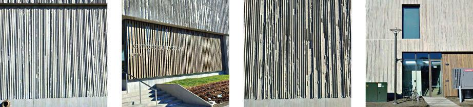
Photographing a Building
When you’re taking photographs to use in Match Photo, keep the following tips in mind: ☑ Do not use any special lenses on your camera. A typical, inexpensive camera or even a phone camera will work just fine.
☑ Walk around the entire site and photograph the entire building from every angle possible.
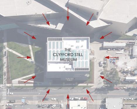
☑ Too many pictures are better than too few. When you’re working at 2:00 a.m., you don’t want to need more than you shot.
☑ Do not crop or resize the images before you import them into SketchUp.
creating a Mass Model
To create a building mass model, follow these steps:
1. For now, hide the four context models and the proposed building mass. To do this, select all of them, right-click on the selection, and choose Hide.
2. Click on the File drop-down menu and select the Geo-Location menu. Uncheck the Show Terrain option so that only the flat 2D aerial imagery is showing.
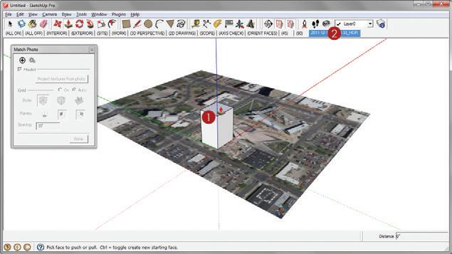
3. Activate the Rectangle tool and click once on the top-left corner of the building footprint.
4. Move your cursor away from the start point and click again on the bottom-right corner of the building footprint to finish the rectangle (Figure 16.7). There is no need for precise dimensions on this geo-model.

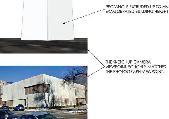
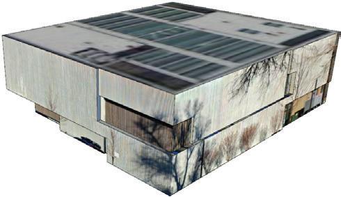
5. Use the Push/Pull tool to extrude the rectangle up to an exaggerated height as shown in Figure 16.8.
6. Set the origin at an appropriate starting point for sketching. For this model, and most others, set the axes at the front-bottom corner of the model when viewing the model from a vantage point similar to the Match Photo photograph.
7. Within SketchUp, position yourself in a view similar to the photograph you are using for Match Photo (Figure 16.9).
Using Match new Photo
To use the Match Photo interface, follow these steps:
1. Click on the Camera drop-down menu and choose Match New Photo.
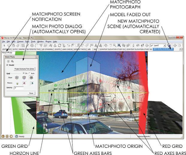
2. Navigate to your Project Files folder and select the Match Photo image BIC_01Clyfford Still Museum.jpg . Click on Open to return to SketchUp; an admittedly intimidating grid will appear over the photograph. Take a moment to study the image in Figure 16.10.
3. Navigate the Match Photo interface using familiar mouse navigation techniques. Push down and hold the scroll-wheel button to pan the screen up, down, left, and right. Roll the scroll-wheel toward the screen to zoom in, and away from the screen to zoom out. Click outside of the Match Photo photograph to exit Match Photo mode.
TIP To get back to Match Photo mode, right-click on the automatically created Match Photo Scene tab and choose edit Matched Photo.
4. In the Match Photo dialog box, uncheck the Model check box to turn off the model and clarify the Match Photo screen, which will make working with the Match Photo interface much easier.
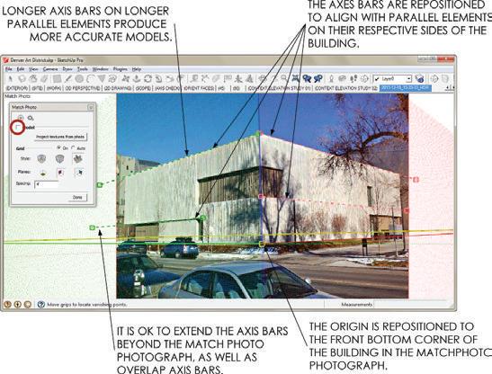
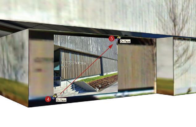
5. Align the axis bars with parallel elements on the building, such as window headers and mullions, ledges, and roof lines. The green axis bars should be aligned with parallel elements on the west side of the building, and the red axis bars should be aligned with parallel elements on the south side of the building (Figure 16.11).
TIP Avoid using the ground plane as a parallel element because it will never be perfectly parallel with the building.
6. Position the Match Photo origin at an appropriate starting point for sketching (Figure 16.12). This will be at the same front-bottom corner you positioned the axes at in the beginning of the exercise.
7. In the Match Photo dialog, turn on the model.
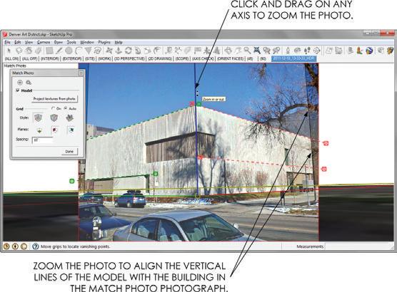
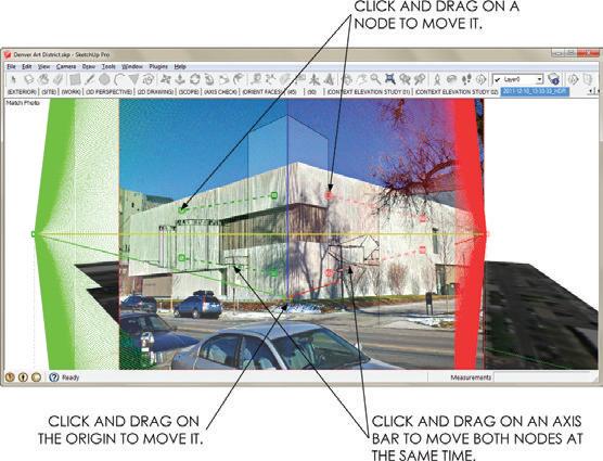
8. Zoom the Match Photo photograph to match the model by clicking and dragging on an axis until the vertical walls of the SketchUp model match the walls of the Match Photo photograph (Figure 16.13). The footprint is correct now; that is why you align the vertical walls. The building height is not yet correct and should be ignored for now because it was drawn at an exaggerated height.
9. In the Match Photo dialog, click the Done button.
Setting Building height
To accurately set the height of the building, follow these steps:
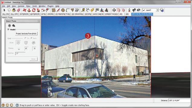
1. Orbit to a bird’s eye view. Activate the Push/Pull tool and click once on the top of the building (Figure 16.14).
2. Click on the Match Photo Scene tab to get back to Match Photo mode.
3. Move your cursor down until the top of the 3D building mass is aligned with the top of the building in the photograph (Figure 16.15). Click to finish the Push/ Pull command.
4. Take a moment to orbit around and inspect the 3D mass model.
The building width and height are now accurately set. You know this because the building length and width are derived from the building footprint imported from Google Earth. The height of the building is accurately determined by reverse engineering a perspective photograph and aligning it with the known building footprint.
Adding 3D Detail
To add detail to your model, follow these steps:
1. Once again, click on the Match Photo scene tab at the top of your screen.
2. In the Match Photo dialog, click on Project Textures to apply the Match Photo photograph to the 3D surfaces. This is what makes a geo-model so “light.” The detail is held in a photograph rather than represented by 3D geometry.
3. Orbit to a 3D view, and then trace over the applied texture images using the SketchUp Drawing tools to create the major breaks in the facades.
4. Use the Modification tools to turn those breaks in the surfaces into further developed 3D details. Go back to the Match Photo scene to use the photograph as a guide for modeling. Draw from other photographs and your own experience when modeling.
5. Using the Paint Bucket tool, hold the Alt key (Command on Mac) to sample the Google Earth Snapshot, then apply the Google Earth Snapshot to the roof (Figure 16.16).
TIP you can gather additional texture images by using google Street View in SketchUp. The imagery pulled from Street View is not nearly as high-resolution as an imported image or Match Photo, but it is often all you need to generate detail on a context building that you can’t photograph in person. right-click on a surface and choose Add Photo Texture to launch the Street View imagery dialog.
importing 2D Detail
Match Photo is best used to create the broad strokes of a model, or the massing in general. Once a building mass is complete, you can use imported images to add high-resolution texture images where they are needed. Use the import image as material technique to replace low-resolution match photo materials with your high-resolution close-up photographs.
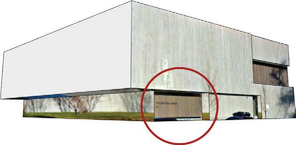
1. Zoom in on the entry of the building (Figure 16.17).
2. Click on the File drop-down menu and choose Import.
3. Verify that the Files of Type drop-down menu is set to All Supported Image Types , and the “Use as Texture” radio button is on. Navigate to the class files folder for this chapter and select BIC_02 - Clyfford Still Museum Entry.jpg . Click the Open button.
4. Click once directly on the surface to place the image (Figure 16.18).
5. Move your cursor away from the start point to loosely scale the image; click again to finish the import. The image will repeat, or tile, across the surface.
Tweaking a Texture
You can use the Texture Tweaker pins to fine-tune your texture images. Just follow these steps:
1. Right-click on the surface with the new image, and select Texture c Position to modify the imported texture image.
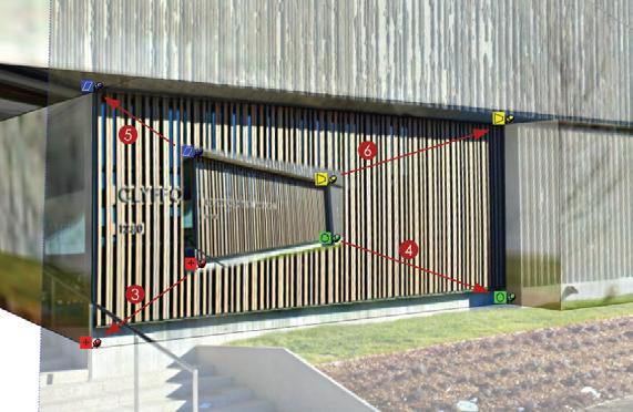
2. Each of the Texture Tweaker fixed pins has a specific job for modifying the texture image. Click once on a pin to pick it up, and click again to put it down. Reposition the four pins on the four corners of the entry wall in the photograph shown in Figure 16.19.
3. Click and drag the red pin to the bottom-left corner of the entry wall in the model. This will move the entire texture image (Figure 16.20).
4. Click and drag the green pin to the bottom-right corner of the entry wall in the model. This will properly scale and rotate the image to align with the model (Figure 16.20).
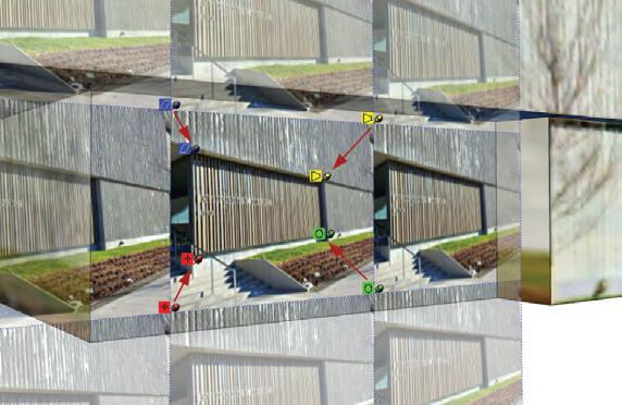
5. Click and drag the blue pin to the top left corner of the entry wall in the model. This will properly scale and shear the image to further align with the model (Figure 16.20).
6. Click and drag the yellow pin to the top-right corner of the entry wall in the model. This will properly distort the image so that it fits the entry wall perfectly (Figure 16.20).
7. Press the Enter key to finish the Texture Tweak and apply the changes (Figure 16.21).
TIP Another way to remove unwanted objects from a texture image is to use an external image editor. right-click on a surface with a texture applied to it and select Texture c edit Texture image. This will open the texture image in the assigned image editor.
Making Unique Materials
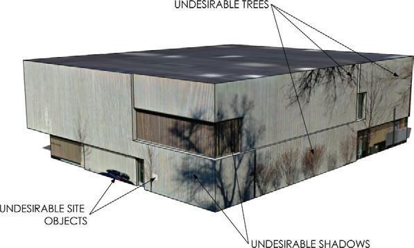
The Make Unique Material feature allows you to find a good chunk of one material and make another unique material from that. You can apply the new, optimized material to the rest of the model, eliminating trees, shadows, and low-resolution texture images (Figure 16.22).
1. Draw a rectangle around a piece of the scored concrete that is free of trees, shadows, and objects. A projected texture image’s quality will be best toward the foreground of the Match Photo image (Figure 16.23).
2. Right-click in the rectangle and select Make Unique Texture. This will create a new material cropped to the extents of the rectangle.
3. Activate the Paint Bucket tool. Hold down the Alt key (Command on Mac) and click on the new unique material to sample it, making it the current material.
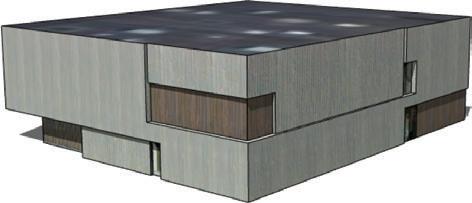
4. To apply the new, optimized material, click on surfaces that have a lower-resolution texture image (Figure 16.24).

Another benefit to making a material unique is that you eliminate pieces of images that are not being used, resulting in smaller file sizes.
1. Right-click on the front-entry walltexture image and select Make Unique Material. You won’t see a difference in your model, but everything in the image that is not shown on the surface will be deleted.
TIP View your designs in the context of the real world in google earth. google earth lets you view all context in the entire city as well as 3D terrain that extends as far as the eye can see. click on the file drop-down menu and choose Preview in google earth.
Continue to use the import texture image and make unique texture strategies to further develop and add detail to the Clyfford Still Museum context model.
creating Scenes
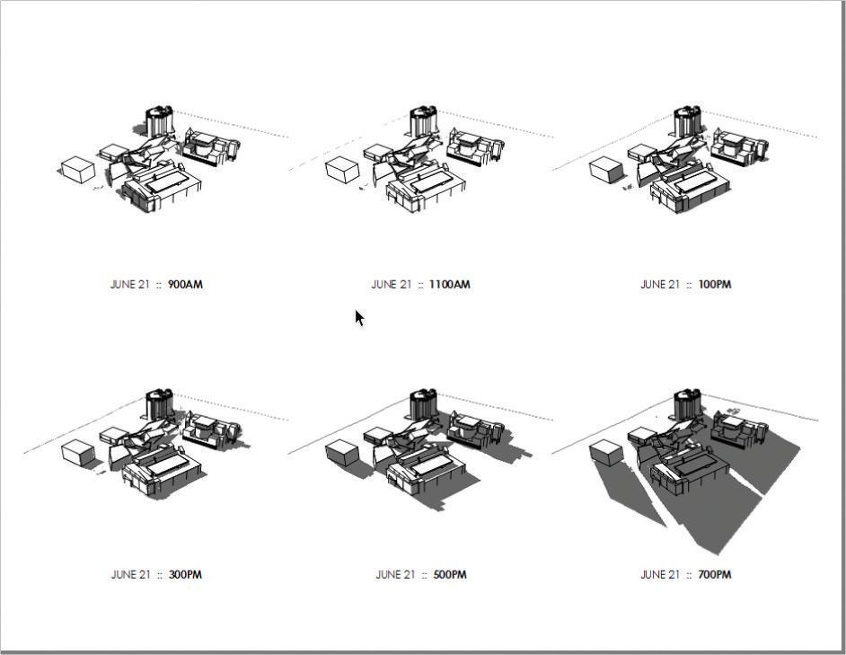
Now that the proposed building and context are in a model, you can closely study the interaction between a proposed design and existing site conditions. One way to do this is through a shadow study. Create scenes to illustrate the effects of shadows on your neighbors. Just follow these steps:
1. Orbit to a 3D perspective view, click on the Edit drop-down menu, and choose Unhide c All.
2. To switch to a line-drawing style and turn on the shadows, click on the 2D DRAWING Scene tab at the top of your SketchUp template.
3. Adjust the shadow settings time to 9:00 a.m.
4. In the Scenes browser, click on the plus sign (+) to add a scene.
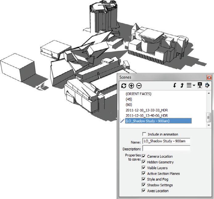
5. Rename the scene LO_ Shadow Study - 900AM and check on all of the Properties to Save . Move the scene to the bottom of the list using the “Move Scene Down” button in the Scenes dialog (Figure 16.25).
6. Repeat steps 3 through 5 for the following scenes: 1100AM, 100PM, 300PM, 500PM, and 700PM. Adjust the shadow time to the respective scene name.
7. Save the model to your TEMP folder or a logical project folder. Name the file BIC_Golden Triangle Museum District.skp.
TIP Purge your models to completely remove unused entities. click on the Window drop-down menu and choose Model info. in the Statistics tab, click on Purge Unused to remove all unused layers, materials, styles, and components. Purging before saving often drastically reduces the size of the file.
Now that you have the context models, you might want to send them over to your favorite 2D or 3D CAD program. To do that, follow these steps:
1. Right-click on the surface of an elevation and select Align View.
2. Click on the View drop-down menu and choose Zoom Extents.
3. Click on the File drop-down menu and select Export c 2D Graphic.
4. Set the Export Type to .dwg /.dxf and click the Export Options button to select a .dwg format.
5. Click the Export button to finish.
lAyoUT Di A gr AMS
To create and annotate a shadow study, send the SketchUp model to LayOut. Just follow these steps:
1. Within SketchUp, click on the File drop-down menu and choose Send to LayOut.
2. Within LayOut, select the BIC_8.5x11 – Landscape template (or your favorite template or title block).
3. Move and scale the viewport so that it takes up the top-left one-sixth of the page.
4. Select the viewport; in the SketchUp Model Inspector, assign the LO_Shadow Study900AM scene.
5. Shadows must render as rasters, and lines look best when rendered as vectors. Therefore, set the viewport to render as Hybrid.
6. While holding down the Ctrl key, click and drag on the viewport to make a copy.
7. In the SketchUp Model Inspector, change the scene to LO_Shadow Study - 1100AM.
8. Repeat steps 6 and 7 for each additional shadow study scene.
9. Below each image, add text that indicates the time of day (Figure 16.26).
TIP it is possible to modify a viewport’s style and shadow settings in the SketchUp Model inspector, although it is almost always better to assign these properties to a scene in SketchUp and then assign each scene to a viewport in layout.
c h APT er Poin TS
☑ For those really tricky buildings that you just can’t see on Street View and can’t take any worthwhile pictures of, try using Building Maker. Building Maker uses multiple aerial shots combined with simple Shape tools to create photo-textured models. Click on the File drop-down menu and choose Building Maker c Add New Building.
☑ Market your firm with an online portfolio of geo-models representing completed projects. Submit your designs to be included in Google Earth through the 3D Warehouse upload. Click on the File drop-down menu and choose 3D Warehouse > Share Model.
☑ There are other, more advanced techniques for using Match Photo. View a tutorial that explains how to use multiple Match Photos to further advance the Clyfford Still Museum model at www.suexch.com/TSWFA.
☑ Match Photo is best for creating the building mass. Use a combination of projected photos and higher-resolution imported photos to get the best results. Use the texturetweaking tools to optimize higher-resolution photo-textures.
☑ Geo-modeling is not an exact science. Don’t hesitate to sketch in minor details to make the model more complete.


