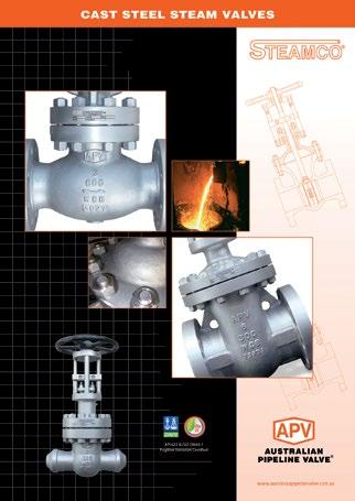
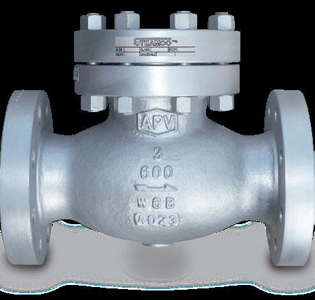
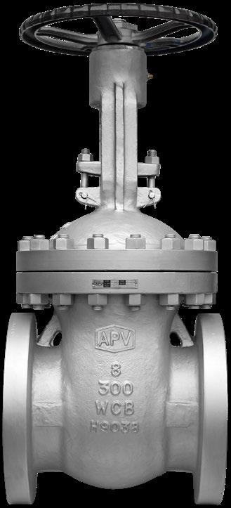
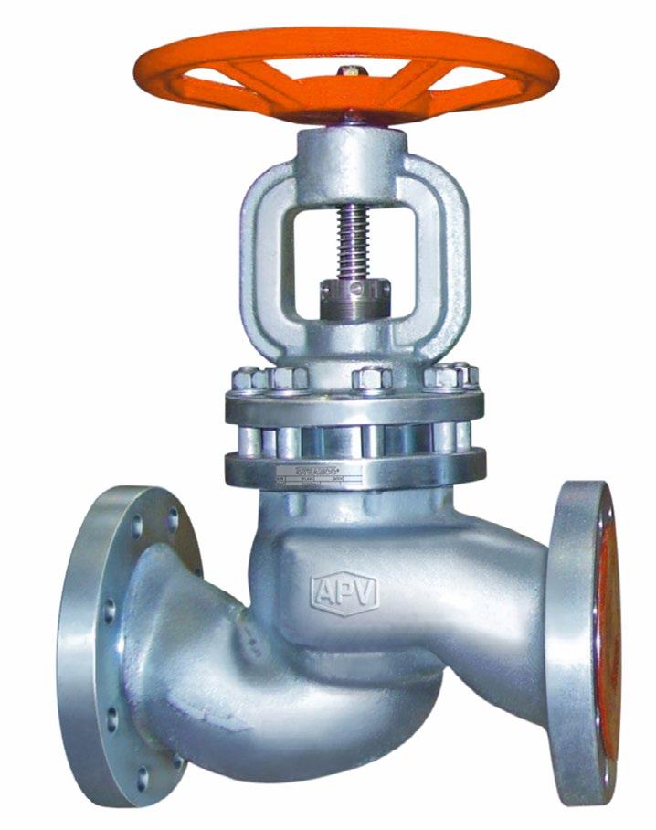
CAST STEEL STEAM VALVES


Quality is Our First Priority.
Consistent product quality and a proven track record makes Australian Pipeline Valve a dependable choice where total reliability is the number one concern.
Since its founding, APV’s philosophy has been focused on quality. Our valves are manufactured in full compliance to worldwide standards (such as ASME/ANSI, API, EN, ISO, BS, AS).

Bonnet gasket:
Blank Standard:- SS + GRP (BB), Pressure Seal Ring (PSB). N/A:- (WB). A SS + PTFE B S318 03 Spiral C PTFE
D SS + PTFE + GRP E Ring Z Special
Stem packing: Blank Standard:- Graphite. N/A:- (Check Valves) L Live Loaded F Fugitive Emission GRP I Fugitive Emission PTFE J Special P Graphite + PTFE T PTFE
Denotes special suffix - Packing/Gasket
Operator: Blank Handwheel or N/A A Actuator C Counter-Weight D Dampner G Gear H Hammer Blow Handwheel L External Lever
End connection: Blank RF (B16.5) BA RF B16.47A (MSS SP44)
BB RF B16.47B (API 605) RJ RTJ BW Buttweld FF Flat Face SP is special drilling UD Undrilled UM Unmachined for RF/RJ
Bonnet: Blank Bolted C Cryogenic H Pillar & Bridge L Low Temperature P Pressure Seal S Bellows Sealed W Welded
Body material: - see page 5. (WCB is Blank)
Denotes special suffix - Body/Bonnet/Ends/Operator
Blank Non NACE N NACE
Blank Standard Configuration (Example Solid Wedge) A S Bend Globe D Globe-Stop Check
DG Globe - Stop Check Guided F Flexible Disc Gate J Slab Gate K Expanding Gate L Lever (Swing Check)
P Full Opening Swing Check (API 6D) Q Full Opening Piston Check (API 6D) R Right Angle S Parallel Slide Y Inclined Bonnet Z c/w Spring
Denotes trim - Code & Modifier (see below)
Basic identifier number denoting valve class and valve type (As shown in catalogue)
Prefix: Blank APV FZV APV-FZV J.V.
Valve Size
BODY MATERIAL CODE • BODY/BONNET MATERIALS
A890/A995-4A/CD3MN Duplex (F51)
A995-6A/CD3MWCuN
AL-Bronze
Duplex (F55)
B62/LG2/B148
A995-5A/CE3MN Super Duplex (F53) 22 A296 M-35 Monel 23 A296 CW-12M Hastelloy C 24 A484 CU-5M CUC Inconel 825 25 A494 CY40 Inconel 600
A494 CW6MC Inconel 625
B367 GR.C2
Titanium (F2) 28 B367 GR.C3
Titanium (F3) 29 A358 LC4 Low Temp. 4-1/2% Nickel Steel 30 A358 LC9 9% Nickel Steel
31 A358 CA6NM 18-1/2% Chromium, Nickel-Molybdenum Steel
32 A217 WC4
33 A217 WC5
34 A217 WC11
35 A217 C12
36 A217 C12A
37 A217 CA15
0 SPECIAL
Nickel Chromium Molybdenum
Nickel Chromium Molybdenum
Chromium Molybdenum
Chromium Molybdenum
Chromium Molybdenum Vanadium
Chromium Steel
PHYSICAL & CHEMICAL PROPERTIES
CAT P316S CLASS 150-900
For superheated steam etc. consult chart.
for
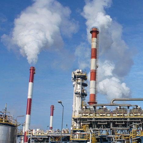
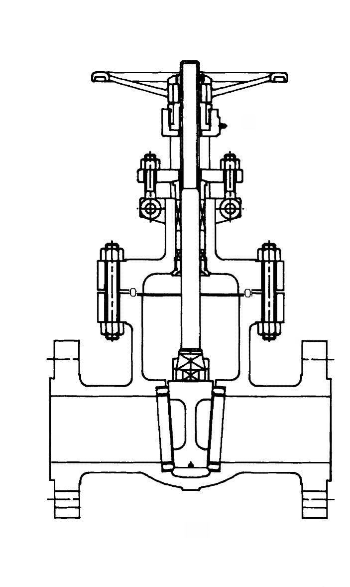
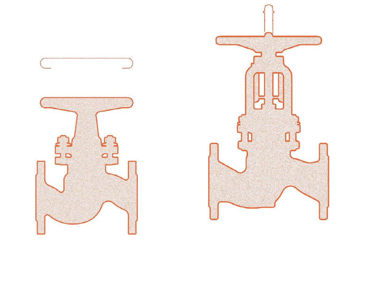
For installation in applications such as industrial, mining and mechanical services. Suitable for super-heated steam, H.T.H.W steam condensate and water.
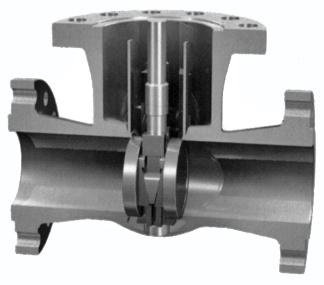
This design consists of two discs, kept in contact with parallel body seats, using the line pressure and seating action to effect tight closure.
Temperature changes in the line are accommodated by the expanding disc & do not affect the action of the valve. When being opened or closed, the discs slide across the seat faces, dislodging any foreign matter. The valve operating stem is outside screw rising through the handwheel.
These valves are suitable for full bore steam use, where a low pressure drop across the valve is required. Also suitable for water, oil, gas, etc.
STANDARD MATERIAL SPECIFICATIONS
Part Material
1 Body ASTM A216 WCB
2 Seat ASTM A105+ST#6
3 Spring Inconel X-750
4 Disc Support Guide ASTM A105
5 Disc ASTM A105+ST#6 6 Stem (1) ASTM A182 F6A 7 Bolt ASTM A193 B7 8 Nut ASTM A194 2H
9 Gasket Spiral Wound SS316 + Graphite 10 Bonnet ASTM A216 WCB
11 Back Seat ASTM A274 410SS
12 Packing (2) Flexible Graphite
12A Packing (2) Braided Graphite
13 Spacer Ring ASTM A276 410SS
14 Gland ASTM A276 410SS
15 Yoke Flange ASTM A276 WCB
16 Nut ASTM A194 2H
Bolt ASTM A193 B7 18 Pin AISI 1020
Yoke ASTM A216 WCB
Grease Nipple SS304
Stem Nut ASTM A439 D2 22 Gland Nut AISI 1035 23 Handwheel Malleable Iron 24 Locking Nut AISI 1035 (1) Stem smoothness Ra ≤ 0.80 µm (2) Stuffing box smoothness Ra ≤ 3.2 µm (superior to API 600)
Basic Design API 600, ANSI B16.34, BS 5157
Face to Face Dimension ANSI B16.10
End to End Dimension ANSI B16.10
Flanged Ends ANSI 16.5
B.W. Ends ANSI B16.25
Drilling to ANSI or BS/AS 2129 Table D to H or AS 4087 / AS 4331 / ISO 7005-1 PN 10 to 250
Pressure/Temperature Ratings to ANSI B16.5
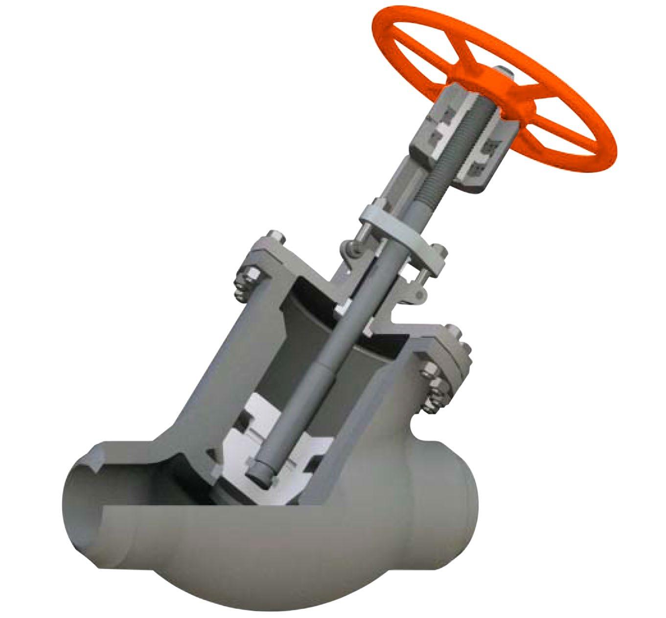
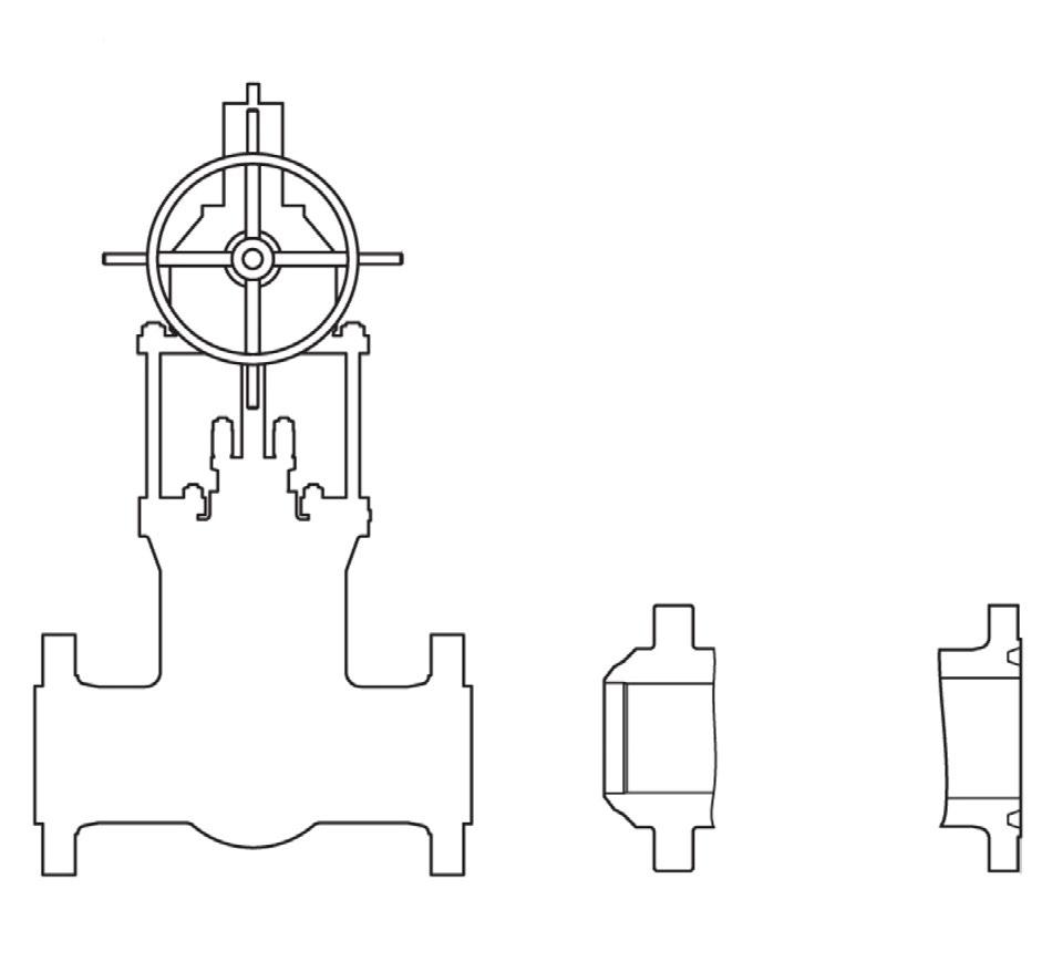
O.S. & Y. Rising Stem Full Port, Expanded Parallel Slide Gate Valve, Double Disc, Pressure Seal or Bolted Bonnet, Welded-in or Threaded Seat Rings. Mechanically loaded seating for low and high pressure sealing.
Parallel slide dual loaded discs ensure superior shut off and allow by-pass/bleed fitment (double block and bleed requires soft seat inserts).
Pressure/temperature charts available on request.
CAT P316S CLASS 150-900
* Add XU modifier to end of model suffix if stellite seat, if stellite seat & disc add U modifier to end.
Note: 15mm to 40mm NB 150 ~ 2500 Class also available refer to individual drawings.
PRESSURE/ TEMPERATURE WCB BODY
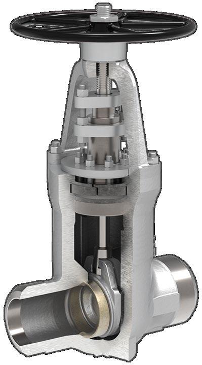
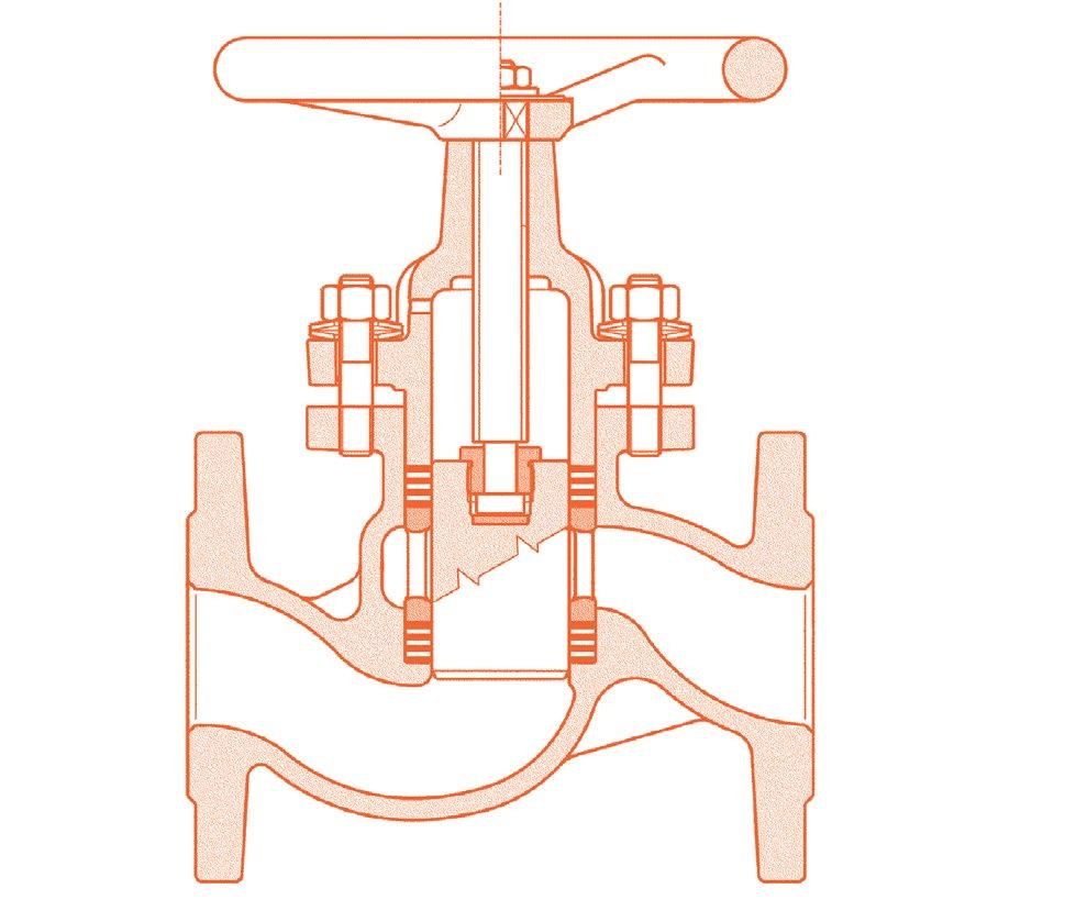
The P316H style parallel slide is the same dimensions as the P316S except has pillar & bridge type top works. The P316H has spring energised discs. For installation in applications such as industrial, mining and mechanical services. Suitable for super-heated steam, H.T.H.W steam condensate and water.
This design consists of two discs, kept in contact with parallel body seats, using the tension spring to effect tight closure.
Temperature changes in the line are accommodated by the energised discs and do not affect the action of the valve. When being opened or closed, the discs slide across the seat faces, dislodging any foreign matter. The valve operating stem is outside screw rising through the handwheel (OSY).
These valves are suitable for full bore steam use, where a low pressure drop across the valve is required. Also suitable for water, oil, gas, etc.

Spring Inconel X750
Spring Coil AISI 410
Parallel Disc ASTM
For superheated steam etc. consult chart. * WC6 chrome-moly available body for high temperature applications.
Yoke Plate 1025
Bolt ASTM A194 Gr. 2H
Supporting Disc 1025
Stem Nut D-2
Retaining Nut 1035
Handwheel A47
Handwheel Nut 1035
Basic Design API 600/BS EN 1984/S 5157/ANSI B16.34
Face to Face Dimension ANSI B16.10
End to End Dimension ANSI B16.10
Flanged Ends ANSI 16.5
B.W. Ends ANSI B16.25
Drilling to ANSI, BS/AS 2129 Table D to H or AS 4087/AS 4331.1/ISO 7005-1/EN 1092-1/PN10 to 250
Pressure/Temperature Ratings to ANSI B16.34/BS 1560
O.S. & Y. Rising Stem, Full Port, Expanded Parallel Slide Gate Valve, Double Spring energised Discs, Pressure Seal or Bolted Bonnet, Welded-in or Threaded Seat Rings. Spring energised loaded seating for low and high pressure sealing.
Parallel slide dual loaded discs ensure superior shut off and allow by pass/bleed fitment (double block and bleed requires soft seat inserts).
CAT P316H CLASS 150-1500
* Add XU modifier to end of model suffix if stellite seat, if stellite seat & disc add U modifier to end. OVERALL
(MM) & WEIGHT (KG)
Note: 15NB to 40NB 150 ~ 2500 Class also available. Refer to drawings.
CAT P316K CLASS 150-1500
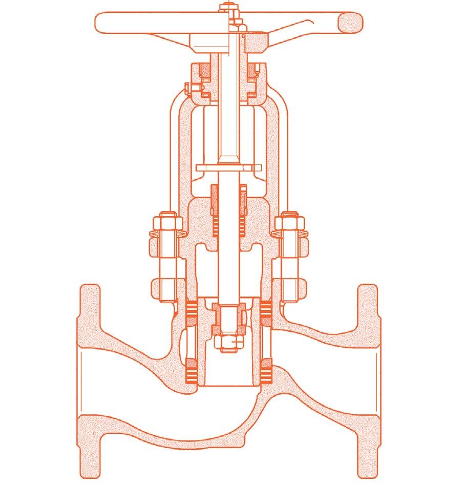
Expanding style parallel slide gate valve suitable for super-heated steam, H.T.H.W steam condensate and water.
Temperature changes in the line are accommodated by the expanding disc and do not affect the action of the valve. When being opened or closed, the discs slide across the seat faces, dislodging any foreign matter. These valves are suitable for full bore steam use, where a low pressure drop across the valve is required.
Also suitable for water, oil, gas, etc.
O.S. & Y. Rising Stem Full Port, Expanded Parallel Slide Gate Valve, Double Disc, Pressure Seal or Bolted Bonnet, Welded-in or Threaded Seat Rings. Mechanically loaded seating for low and high pressure sealing.
Parallel slide dual loaded discs ensure superior shut off and allow by-pass/bleed fitment (double block and bleed requires soft seat inserts).
Pressure/temperature charts available on request.
STANDARD MATERIAL SPECIFICATIONS
For superheated steam etc. consult chart. WC6 chrome-moly available body for high temperature applications.
Part Material
1 Body ASTM A217 WCB
2 Seat Ring ASTM A105+STL.6
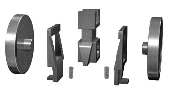
3 Wedge Blocks ASTM A743 CA40
4 Discs ASTM A105+STL.12
5 Springs Inconel X-750
6 Disc Yoke ASTM A743 C40
7 Guides C.S.
8 Stem ASTM A182 F6A
9 Studs ASTM A193 B7
10 Nuts ASTM A194 2H
11 Gasket 304SS+GRAPHITE
12 Bonnet ASTM A216 WCB
13 Back Seat ASTM A276 410
14 Packing FLEXIBLE GRAPHITE
15 Packing 316+BRAIDED GRAPHITE
16 Gland ASTM A276 410
17 Gland Flange ASTM A217 WCB
18 Pins AISI 1035
19 Eyebolts ASTM A193 B7
20 Nuts ASTM A194 2H
21 Stem Nut ALUMINIUM BRONZE
22 Retaining Nut AISI 1035
23 Handwheel MALLEABLE IRON
24 Nuts AISI 1035
Rivets 316SS
Bearings SUB-ASSEMBLY
Yoke ASTM A216 WCB
Studs ASTM A193 B7
Nuts ASTM A194 2H 31 Grease Nipple BRASS
* Also available with expanding wedge energiser (no spring) style - refer to drawing.
CAT P316K CLASS 150-1500
SPECIFICATIONS
Basic Design API 600, ANSI B16.34
Face to Face Dimension ANSI B16.10
End to End Dimension ANSI B16.10
Flanged Ends ANSI 16.5
B.W. Ends ANSI B16.25
Drilling to ANSI or BS/AS 2129 Table D to H or AS 4087 / AS 4331.1 / ISO 7005-1 PN 10 to 250
Pressure/Temperature ratings to ANSI B16.5
PARALLEL SLIDE GATE VALVES - CAST STEEL * Add XU
OVERALL DIMENSIONS (MM) & WEIGHT (KG)
Note: 15mm to 40mm NB 150 ~ 2500 Class also available refer to individual drawings.
FEATURES
Pressure seal bonnet
Complete flow isolation in either direction
Minimum pressure drop
Inherent self cleaning action
Freedom from leakage, resistant to temperature or pressure changes
In line maintenance
By pass available upon request
SPECIFICATIONS
Basic Design ASME B16.34
Face to Face Dimension ASME B16.10
End Flange ASME B16.5
B.W. Ends ASME B16.25
Test and Inspection API 598
(AS/BST D to F)
(AS/BST H to J)
For installation in applications such as industrial, mining & mechanical services Suitable for super-heated steam, H.T.H.W steam condensate & water. This design consists of two discs, kept in contact with parallel body seats, using the line pressure and sprung seating action to effect tight closure.
Temperature changes in the line are accommodated by the expanding disc & do not affect the action of the valve. When being opened or closed, the discs slide across the seat faces, dislodging any foreign matter. The valve operating stem is outside screw rising through the handwheel.
These valves are suitable for steam use, where a low pressure drop across the valve is required. Also suitable for water, oil, gas, etc.
Basic Design API 602/ANSI B16.34, BS 5157
Face to Face Dimension ANSI B16.10
End to End Dimension ANSI B16.10
Flanged Ends ANSI 16.5
B.W. Ends ANSI B16.25
S.W. Ends ANSI B16.11
Drilling to ANSI or BS/AS 2129 Table D to H or AS 4087 / AS 4331 / ISO 7005-1 PN 10 to 250
Pressure/Temperature Ratings to ANSI B16.5
O.S. & Y. Rising Stem Full Port, Expanded Parallel Slide Gate Valve, Double Disc, Pressure Seal or Bolted Bonnet, Welded-in or Threaded Seat Rings. Mechanically loaded seating for low and high pressure sealing.
Parallel slide dual loaded discs ensure superior shut off and allow by-pass/bleed fitment (double block and bleed requires soft seat inserts).
Pressure/temperature charts available on request. Available in A105N, F22, F11, F5, 316, 304 etc.
For installation in applications such as industrial, mining and mechanical services Suitable for super-heated steam, H.T.H.W steam condensate and water. This design consists of two discs, kept in contact with parallel body seats, using the line pressure and sprung seating action to effect tight closure.
Temperature changes in the line are accommodated by the expanding disc & do not affect the action of the valve. When being opened or closed, the discs slide across the seat faces, dislodging any foreign matter. The valve operating stem is outside screw rising through the handwheel.
These valves are suitable for full bore steam use, where a low pressure drop across the valve is required. Also suitable for water, oil, gas, etc.
PRESSURE/TEMPERATURE A105N BODY
(AS/BST D to F)
For superheated steam etc. consult chart. F11, F22, F5 chrome-moly available body for
STANDARDS COMPLIANCE
Basic Design API 600, ANSI B16.34, BS 5157 Face to Face Dimension ANSI B16.10
End to End Dimension ANSI B16.10
Flanged Ends ANSI 16.5
B.W. Ends ANSI B16.25
S.W. Ends ANSI B16.11
Drilling to ANSI or BS/AS 2129 Table D to H or AS 4087 / AS 4331 / ISO 7005-1 PN 10 to 250
Pressure/Temperature Ratings to ANSI B16.5
Bolted Bonnet O.S. & Y. Rising Stem Full Port, Expanded Parallel Slide Gate Valve, Double Disc, Pressure Seal or Bolted Bonnet, Welded-in or Threaded Seat Rings. Mechanically loaded seating for low and high pressure sealing.
Parallel slide dual loaded discs ensure superior shut off and allow by-pass/bleed fitment (double block and bleed requires soft seat inserts).
Pressure/temperature charts available on request.
Available in A105N, F22, F11, F5, 316, 304 etc. (Pillar & Post style bonnet also available.)
For installation in applications such as industrial, mining and mechanical services. Suitable for super-heated steam, H.T.H.W steam condensate and water. This design consists of two discs, kept in contact with parallel body seats, using the line pressure and sprung seating action to effect tight closure. Temperature changes in the line are accommodated by the expanding disc and do not affect the action of the valve. When being opened or closed, the discs slide across the seat faces, dislodging any foreign matter. The valve operating stem is outside screw rising through the handwheel. These valves are suitable for full bore steam use, where a low pressure drop across the valve is required. Also suitable for water, oil, gas, etc.
PRESSURE/TEMPERATURE
(AS/BST D to F)
(AS/BST H to J) 300-P316SFXU-S
For superheated steam etc. consult chart. F11, F22, F5 chrome-moly available body for high temperature applications.
MATERIAL CODES
Hastelloy B Hastelloy B Hastelloy B Hastelloy B
to end.
Contact us for detailed drawing.
STANDARDS COMPLIANCE
Basic Design API 600, ANSI B16.34, BS 5157
Face to Face Dimension ANSI B16.10
End to End Dimension ANSI B16.10
Flanged Ends ANSI 16.5
B.W. Ends ANSI B16.25
S.W. Ends ANSI B16.11
Drilling to ANSI or BS/AS 2129 Table D to H or AS 4087 / AS 4331 / ISO 7005-1 PN 10 to 250
Pressure/Temperature Ratings to ANSI B16.5
Pressure Seal Bonnet O.S. & Y. Rising Stem
Full Port, Expanded Parallel Slide Gate Valve, Double Disc, Pressure Seal or Bolted Bonnet, Welded-in or Threaded Seat Rings. Mechanically loaded seating for low and high pressure sealing.
Parallel slide dual loaded discs ensure superior shut off and allow by-pass/bleed fitment (double block and bleed requires soft seat inserts).
Pressure/temperature charts available on request. Available in A105N, F22, F11, F5, 316, 304 etc. (Pillar & Post style bonnet also available.)
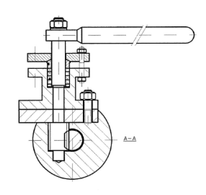
Quick acting - Uniflo style lever or key operated continuous boiler blow down valves (blow off) for installation in applications such as industrial, mining and mechanical services. Suitable for super-heated steam, H.T.H.W steam condensate and water.
This design consists of two discs, kept in contact with parallel body seats, using the line pressure & sprung seating action to effect tight closure. Temperature changes in the line are accommodated by the expanding disc and do not affect the action of the valve. When being opened or closed, the discs slide across the seat faces, dislodging any foreign matter. The valve operating stem is outside screw rising through the handwheel. These valves are suitable for full bore steam use, where a low pressure drop across the valve is required. Also suitable for water, oil, gas, etc. Also available in Globe style, quick acting.
Basic Design ANSI B16.34, BS 5157
Face to Face Dimension ANSI B16.10
End to End Dimension ANSI B16.10
Flanged Ends ANSI 16.5
150 (AS/BST D to F)
300 (AS/BST H to J)
For superheated steam etc. consult chart. F11, F22, F5 chrome-moly available body for high temperature applications.
TRIM MATERIAL CODES
B.W. Ends ANSI B16.25
S.W. Ends ANSI B16.11
Drilling to ANSI or BS/AS 2129 Table D to H or AS 4087 / AS 4331 / ISO 7005-1 PN 10 to 250
Pressure/Temperature Ratings to ANSI B16.5
O.S. & Y. Rising Stem Full Port, Expanded Parallel Slide Gate Valve, Double Disc, Bolted Bonnet, Integral Seal Rings - Metal to Metal. Mechanically loaded seating for low and high pressure sealing.
Parallel slide dual loaded discs ensure superior shut off and allow by-pass/bleed fitment (double block and bleed requires soft seat inserts).
Pressure/temperature charts available on request. Available in A105N, F22, F11, F5, 316, 304 etc.
A182 F5/F5A
Description
Body
Bonnet
Disc
Stem
Hand
Seat
Back
Yoke Sleeve
Sleeve
Gland
Gland
Bonnet
Bonnet
Gland
Gland
Gland
Grease
DIMENSIONS (MM)
DIMENSIONS (MM)
Body
Bonnet
Disc
Stem
Hand
Seat Ring
Back Seat Ring
Yoke Sleeve
Sleeve Gland
Gland Flange
Gland
Bonnet
Gland
Gland
Gland
Bearing
Grease
(MM)
(MM)
STANDARD MATERIAL SPECIFICATIONS
Part Name Materials
1 Body ASTM A216 Gr. WCB
For horizontal installations in applications such as industrial, mining and mechanical services, suitable for H.T.H.W., steam, condensate and water.
WORKING PRESSURE
P143XXXXXXXXXX XU-D 150 CLASS
280 PSI CWP (WOG)
170 PSI Saturated Steam (at 260ºC)
P151XXXXXXXXXX XU-D 300 CLASS
720 PSI CWP (WOG)
600 PSI Saturated Steam (at 260ºC)
P171XXXXXXXXXX XU-D 600 CLASS
1440 PSI CWP (WOG) 1100 psi at 260°C, 825 psi at 400°C.
2 Seat Ring ASTM A105 with HF overlay 3 Disc ASTM A105 with F6 overlay 4 Stem ASTM A182 Gr.
* Fitted on larger sizes & higher classes.
† Gearboxes on larger sizes
Screw-Down Non-Return Globe Valve
Guided loose disc for combination check & stop. Bolted Bonnet, O.S. & Y., Swivel Disc.
STANDARDS COMPLIANCE
Basic Design API 600/BS 1873 & ANSI B16.34
Face to Face Dimension ANSI B16.10
End to End Dimension ANSI B16.10
Flanged Ends ANSI 16.5
B.W. Ends ANSI B16.25
Drilling to ANSI or BS/AS 2129 Table D to H or AS 4087/AS 4331.1/ISO 7005-1/EN 1092-1/PN10 to PN100
*Available in undrilled to accommodate AS/BS or PN/JIS table drilling. ANSI flanges can also be machined to AS/BS table thickness to allow face to face dimension alteration. 1/2” to 1-1/2” see page 44 of APV Cast, Gate, Globe, Check Catalogue (Full Version).
For horizontal installations in applications such as industrial, mining and mechanical services, suitable for super-heated steam, H.T.H.W., steam, condensate and water.
WORKING PRESSURE
P143XXXXXXXXXX XU-D 150 CLASS
280 PSI CWP (WOG)
170 PSI Saturated Steam (at 260ºC)
P151XXXXXXXXXX XU-D 300 CLASS
720 PSI CWP (WOG)
600 PSI Saturated Steam (at 260ºC) For superheated steam consult pressure/temp chart
P171XXXXXXXXXX XU-D 600 CLASS
1440 PSI CWP (WOG)
1100 psi at 260°C, 825 psi at 400°C. For other temperatures consult chart.
Screw-Down Non-Return Globe Valve Cage guided disc for combination check & stop. Bolted Bonnet, O.S. & Y., Swivel Disc
STANDARDS COMPLIANCE
Basic Design API 600/BS 1873 & ANSI B16.34
Face to Face Dimension ANSI B16.10
End to End Dimension ANSI B16.10
Flanged Ends ANSI 16.5
B.W. Ends ANSI B16.25
Drilling to ANSI or BS/AS2129 Table D to H or AS 4087/AS 4331.1/ISO 7005-1/EN 1092-1/PN10 to PN100
Pressure/Temperature Ratings to ANSI B16.34
*Available in undrilled to accommodate AS/BS or PN/JIS table drilling. ANSI flanges can also be machined to AS/BS table thickness to allow face to face dimension alteration. 1/2” to 1-1/2” see page 44 of APV Cast, Gate, Globe, Check Catalogue (Full Version).
STANDARD MATERIAL SPECIFICATIONS
FEATURES
Screw-Down Non-Return Globe Valve Fully guided disc for combination check & stop. Bolted Bonnet, O.S. & Y, Swivel Disc
STANDARDS COMPLIANCE
Basic Design API 623 & ANSI B16.34
Face to Face Dimension ANSI B16.10
End to End Dimension ANSI B16.10
Flanged Endss ANSI 16.5
Globe Valve, Model 250AP151XUD-G, SDNR, NPS 10” (DN250) Class 300, RF, FP, BBOSY, Gearbox
B.W. Ends ANSI B16.25
Drilling to ANSI or BS/AS2129 Table D to H or AS 4087/AS 4331.1/ISO 7005-1/EN 1092-1/PN10 to PN260
Pressure/Temperature Ratings to ANSI B16.34
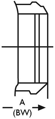
Buttweld ends
For horizontal and vertical (with upwards flow) installations in applications such as industrial, mining and mechanical services. Suitable for super-heated steam, H.T.H.W., steam, condensate & water. Available as a stop valve or stop-check valve.
P143XXXXXXXX XU-D-Y 150 CLASS
280 PSI CWP (WOG)
170 PSI Saturated Steam (at 260ºC)
P151XXXXXXXX XU-D-Y 300 CLASS
720 PSI CWP (WOG)
Customer must specify flow direction (Horizontal or Vertical)
600 PSI Saturated Steam (at 260ºC) For superheated steam consult pressure/temp chart
P171XXXXXXX XU-D-Y 600 CLASS 1440 PSI CWP (WOG)
1100 psi at 260°C, 825 psi at 400°C. For other temperatures consult chart.
* Fitted on larger sizes & higher classes.
† Gearbox or Hammer Blow wheel on larger sizes.
Other Body and Trim materials available such as WC6, ductile iron (250 Class), bronze, etc. see ‘overview brochure’.
DESIGN
Y-Pattern bonnet design allows a straightway flow path which provides a lower pressure drop at equal flow rates compared to conventional straight pattern ‘T-Pattern’ globe valves
FEATURES
Screw-Down Non-Return Globe Valve. Guided loose disc for combination check & stop. Bolted Bonnet, O.S. & Y., Swivel Disc in plug type or parabolic shape.
STANDARDS COMPLIANCE
Basic Design API 600/BS 1873, ANSI B16.34
Face to Face Dimension ANSI B16.10
End to End Dimension ANSI B16.10
Flanged Ends ANSI 16.5
B.W. Ends ANSI B16.25
Drilling to ANSI or BS/AS 2129 Table D to H and PN 10 to 100 Pressure/Temperature Ratings to ANSI B16.34.
For horizontal and vertical (with upwards flow) installations in applications such as industrial, mining and mechanical services. Suitable for super-heated steam, H.T.H.W., steam, condensate & water. Available as a stop valve or stop-check valve.
WORKING PRESSURE
P151XXXXXXXXX XU-D-Y 300 CLASS
720 PSI CWP (WOG) 600 PSI Saturated Steam (at 260ºC) For superheated steam consult pressure/temp chart
† Gearbox or Hammer Blow wheel on larger sizes. Other Body and Trim materials available such as WC6, ductile iron (250 Class), bronze, etc.
Y-Pattern bonnet design allows a larger flow path which provides a lower pressure drop at equal flow rates compared to conventional straight pattern angle globe valves
FEATURES
Screw-Down Non-Return Globe Valve. Guided loose disc for combination check & stop. Bolted Bonnet, O.S. & Y., Swivel Disc in plug type or parabolic shape.
STANDARDS COMPLIANCE
Basic Design BS 1873, ANSI B16.34
Face to Face Dimension ANSI B16.10
End to End Dimension ANSI B16.10
Flanged Ends ANSI 16.5
B.W. Ends ANSI B16.25
Drilling to ANSI or BS/AS 2129 Table D to H and PN 10 to 100
Pressure/Temperature Ratings to ANSI B16.34.
to drawing 15NB
Globe Valve (combination globe & check valve), Bolted Bonnet, O.S. & Y., Swivel Disc (guided loose disc for combination check & stop). Can also be supplied as standard globe stop valve. Drilling to ANSI, AS 2129 Table D to H or AS 4331.1 /ISO 7005-1 / AS 4087 PN10 to 100.

For installations in application such as industrial, mining & mechanical services. Suitable for super-heated steam, H.T.H.W, steam, condensate and water. Stem is guided for smooth operation. Also available in Bronze, Iron, chrome-moly etc.
Customer must specify flow direction (Horizontal or Vertical)
VALVE SIZE (NPS)
CLASS 300 (Table F
A105+STL#6 overlay
Disc ASTM A105+13CR
Disc Cover ASTM A276 410
Stem ASTM A182 F6A
Gasket SS316+Graphite
Bonnet ASTM A216 WCB
Back Seat ASTM A276 410
Bolt ASTM A193 B7
Nut ASTM A194 2H
Packing Graphite
Gland ASTM A216 410
Gland Flange ASTM A216 WCB
Bolt ASTM A193 B7
Nut ASTM A194 2H
Pin AISI 1035
Stem Nut Copper Alloy
Set Screw ASTM A193 B7
Handwheel Malleable Iron
Washer A3+ZP 21 Locking Nut ASTM A194 2H 22 Guide Pin AISI 1035 23 Guide Cage AISI 1035
Note: Other body & trim materials are available upon request, such as bronze.
P143XXXXXXR 150 CLASS
280 PSI CWP (WOG)
170 PSI Saturated Steam (at 260ºC)
P151XXXXXXR 300 CLASS
720 PSI CWP (WOG)
600 PSI Saturated Steam (at 260ºC)
For superheated steam consult pressure/temp chart
P171XXXXXXR 600 CLASS
1440 PSI CWP (WOG)
WC6 body is available for high temperature applications, consult P/T chart.
Globe Valve, Bolted Bonnet, O.S. & Y., Swivel Disc (guided loose disc for combination check & stop). Can also be supplied as standard globe stop valve. Drilling to ANSI, AS 2129 or Table D to H or A 4087/AS 4331.1 / ISO 7005-1 PN10 to 100.
For installations in application such as industrial, mining & mechanical services. Suitable for super-heated steam, H.T.H.W, steam, condensate and water. Stem is guided for smooth operation. Also available in Bronze, Iron, chrome-moly etc.
Customer must specify flow direction (Horizontal or Vertical) Buttweld ends
BS/AS TABLE D, E, ANSI 125, PN10, JIS10
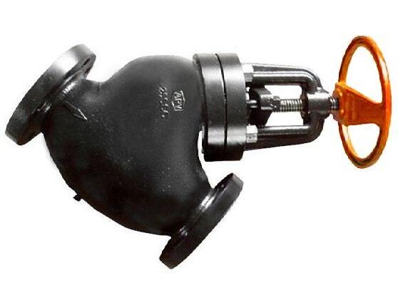
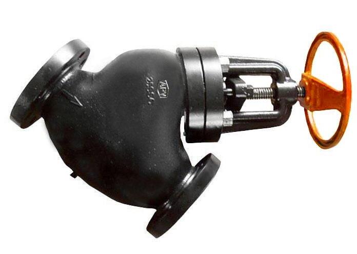
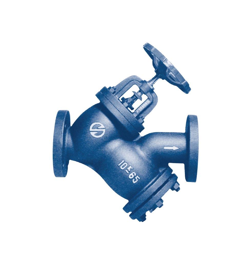
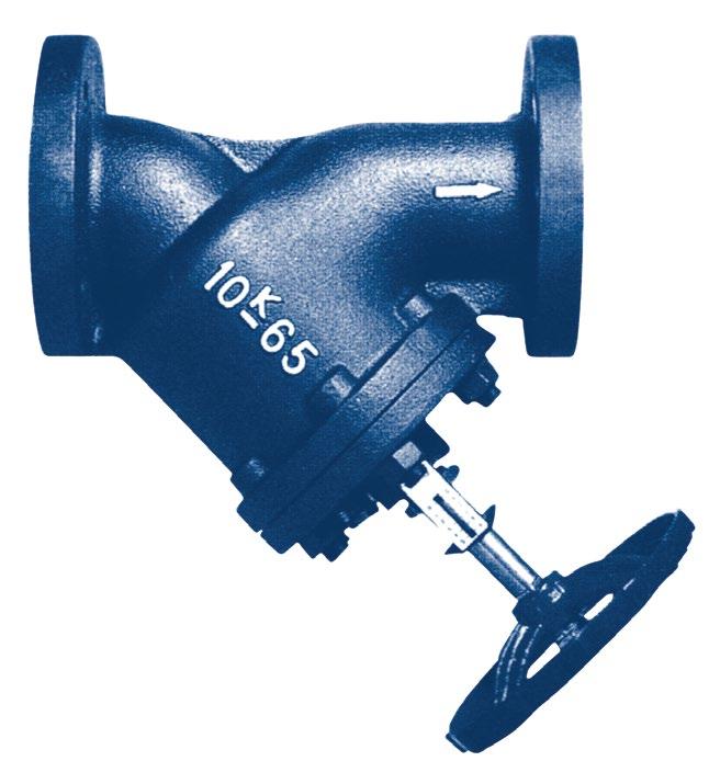
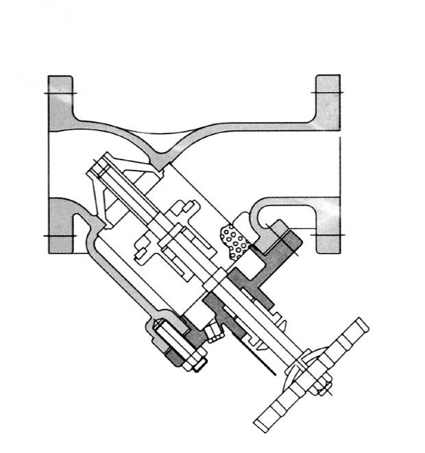
• Y Type for large flow area.
• As a valve having both valve and strainer functions, it is light weight, & can be installed with minimum piping space & effort.
• As Teflon (PTFE) is used for the stem packing, superior corrosion resistance, cold-resistance & abrasion-resistance are achieved. There is no leakage at all, & the valve operates smoothly.
• An indicator is attached to the valve to make it is easy to check the open/close status and to make the fluid volume control possible.
• The valve is designed to eliminate pressure spot in order to prevent fluid resistance or concentration of pressure and thus increase the volume of fluid.
• The open area of strainer screen is 3 times larger than bore area to minimize presssure loss.
• Foreign substances inside the screen can be removed at any time via the drain plug, without removing the bonnet.
• Available with strainer and tamper switch as options (available ISY & OSY)
SPECIFICATIONS
DIMENSIONS
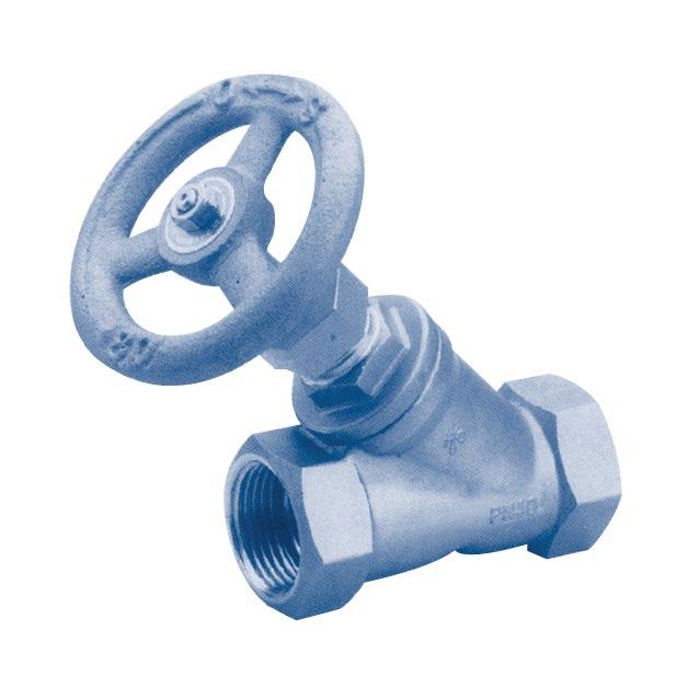
S.D.N.R. GLOBE Y-TYPE 600PSI
Suitable for W.O.G. saturated steam, chemicals etc
Body and bonnet quality investment casting
Metal to metal seat design
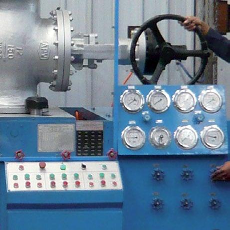
100% air tested under water, at 100 psi, open and closed positions.
Hydrostatic test pressure - 1,200 psi
SPECIFICATIONS
Working Pressure PN40 (600psi) WOG
Temperature Rang -40 to 450°F
End Type Threaded ANSI B2.1, BS21, DIN
ASME B16.10 Class 150, 300 & 800
Face to Face Dimension to ASME B16.10
Also Available in PN16, PN40 & PN63 Flanging Design to ASME B16.34 & EN 12526-2
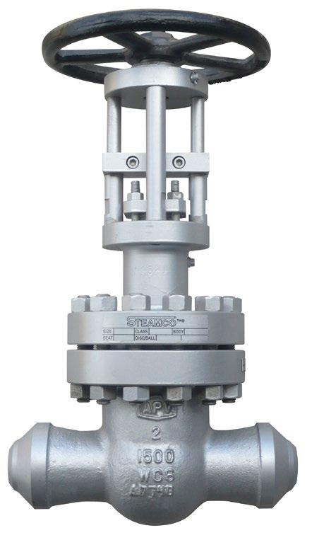
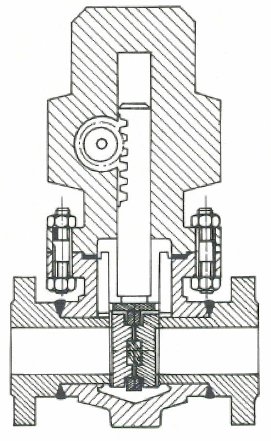
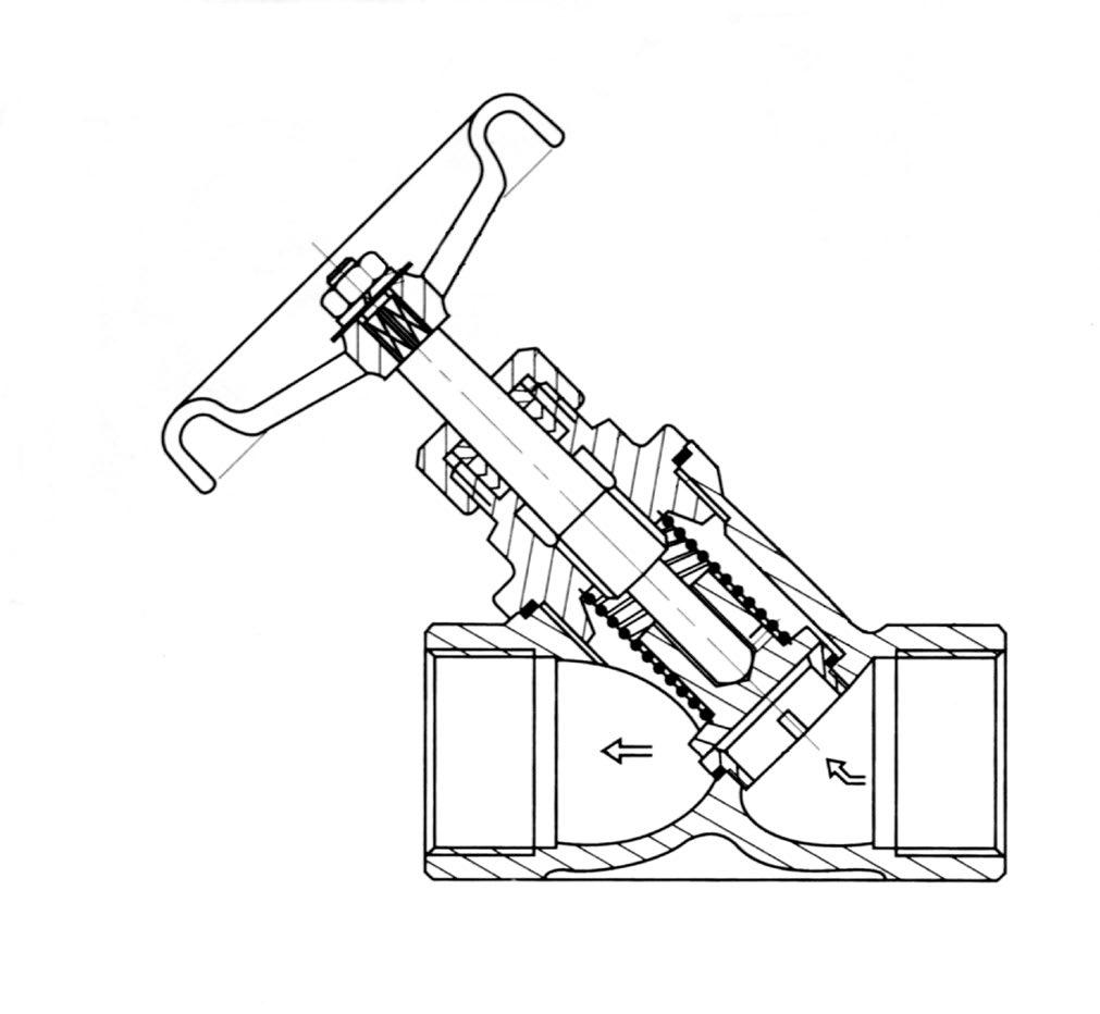
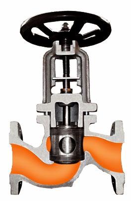
Piston valves are used to regulate and control steam as well as highly aggressive media in the chemical industry as well as for fine regulating in the oil industry. Piston valves are leak tight on the seat (ANSI CL VI) as well as through the body to the atmosphere.
Steamco piston valves are a true isolation valve whilst still allowing a degree of flow regulation. The Piston valve has a superior system to a conventional globe valve, it has a cylindrical piston & two resilient, replaceable jointing rings. Balance piston option is available to address high torque requirements in sizes above 65NB.
Advantages of Piston valves -
• Exceptional leak tightness across the ports and to atmosphere
• Insensitive to impurities due to the combination sealing system
• Maintenance free
• Unaffected by wire drawing in steam service
• Environmentally safe and energy efficient
• Inherently fugitive emission design
• Valve rings are replaceable in line
• Excellent control statistics
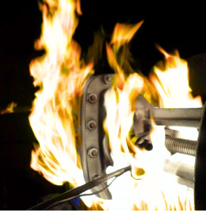
• Inherently fire safe design
• High return on investment across full service life compared to globe valves
Cast Iron, Carbon Steel, Stainless Steel Valves ASME Class 125, 150, 300, 800 – PN 16/40/63
• Size 6NB to 200NB (¼” to 8”)
• Standard female screwed ends:
- B.S.P. – NPT – ASME B1.20.1
• Socket weld ends – SW to:
- ASME B16.11
• Butt weld ends to:
- ASME B16.25 and pipe Sch 160
• Flanged ends to:
- ASME B16.5
- AS 2129
- AS 4087
- AS 4331 (ISO 75005-1)
- EN 1092
Materials/Class (End Connections)
Cast Steel/Class 150 (Flanged End)
Cast Steel/Class 300 (Flanged End)
Cast Steel/Class 300 (Screwed/Socket-weld)
Cast Steel/Class 150 (Flanged End)
Forged #800: DN15, 20, 25 - Angle pattern; DN25, 40 - Straight pattern. Weld-on flanges available
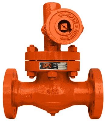
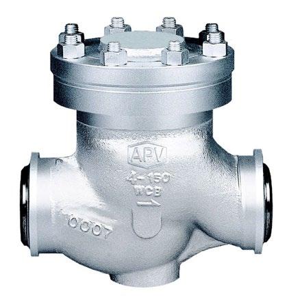
Non return Piston Check valve, lift type, bolted bonnet, guided disc. Flange drilling ANSI 150 to 600 and AS2129 table D to H and PN10 to 100.
For horizontal installations in applications such as industrial, mining and mechanical services. Suitable for super-heated steam, H.T.H.W., steam, condensate and water. Guiding of stem assures smooth operation. Other body materials like Bronze and WC6 also available.
(Guiding mechanism varies according to size class, refer to drawing)
SLCLXU-Z 150 CLASS
280 PSI CWP (WOG)
170 PSI Saturated Steam (at 260°C)
SLCLXU-Z 300 CLASS
720 PSI CWP (WOG)
600 PSI Saturated Steam (at 260°C) For superheated steam consult pressure/temp chart
SLCLXU-Z 600 CLASS
1440 PSI CWP (WOG)
1100 PSI at 260°C, 825 psi at 400°C. Consult chart for other temperatures WC6 body is available for high temperature applications
OVERALL
(Table D to F) (PN10~21)
CLASS 300 (Table F to H) (PN25~50)
(RF-BW)
Gasket Stainless Steel/Graphite
Bonnet/Guide ASTM A216 Gr. WCB
Bonnet Nut ASTM A194 Gr. 2H
Bonnet Bolt ASTM A193 Gr. B7
Spring Inconel X750
Gasket Graphite
*1 Spring Optional. *2 Drain Optional.
Basic Design API 600/BS 1873 and ANSI B16.34
Face to Face Dimension ANSI B16.10
End to End Dimension ANSI B16.10
Flanged Ends ANSI 16.5
B.W. Ends ANSI B16.25
Drilling to ANSI or BS/AS 2129 Table D to H and PN10 to 100
(MM & INCHES) & WEIGHT (KG)
Non return Piston Check valve, lift type, bolted bonnet, guided disc. Flange drilling ANSI 150 to 600 & BS/AS2129 table D to H, and PN10 to 100.
For horizontal installations in applications such as industrial, mining and mechanical services. Suitable for super-heated steam, H.T.H.W., steam, condensate and water.
Guiding of stem assures smooth operation.
Other body materials like Bronze and WC6 also available. (S-Bend Type Body shown)
STANDARD MATERIAL SPECIFICATIONS
1 Body/Guide ASTM A216 Gr. WCB 2 Seat Ring ASTM A105 with HF overlay
SLCLXU-Z 150 CLASS
280 PSI CWP (WOG)
170 PSI Saturated Steam (at 260°C)
SLCLXU-Z 300 CLASS
720 PSI CWP (WOG)
600 PSI Saturated Steam (at 260°C) For superheated steam consult pressure/temp chart
SLCLXU-Z 600 CLASS
1440 PSI CWP (WOG)
1100 PSI at 260°C, 825 psi at 400°C. Consult chart for other temperatures WC6 body is available for high temperature applications
Spring Activated Buttweld
Inconel X750 10 Gasket Graphite 11*2 Drain Plug A105N
*1 Spring Optional. *2 Drain Optional.
STANDARDS COMPLIANCE
Basic Design API 600/BS 1873 and ANSI B16.34
Face to Face Dimension ANSI B16.10
End to End Dimension ANSI B16.10
Flanged Ends ANSI 16.5
B.W. Ends ANSI B16.25
Drilling to ANSI, BS/AS 2129 Table D to H or PN10 to 100
(Table D to F) (PN10~21)
CLASS 300 (Table F to H) (PN25~50)
Non return Piston Check valve, lift type, bolted bonnet, guided disc. Flange drilling ANSI 150 to 600 and AS 2129 table D to H and AS 4087/EN/ISO PN10 to 100. Guide pin and cage and/or bonnet guide cage as required (refer to drawings). For horizontal installations in applications such as industrial, mining and mechanical services. Suitable for super-heated steam, H.T.H.W., steam, condensate and water. Guiding of stem assures smooth operation. Other body materials like Bronze and WC6 also available.
Centre Guided Style
SLCLXU-Z 150 CLASS
280 PSI CWP (WOG)
170 PSI Saturated Steam (at 260°C)
SLCLXU-Z 300 CLASS
720 PSI CWP (WOG)
600 PSI Saturated Steam (at 260°C) For superheated steam consult pressure/temp chart
SLCLXU-Z 600 CLASS
1440 PSI CWP (WOG)
1100 PSI at 260°C, 825 psi at 400°C. Consult chart for other temperatures WC6 body is available for high temperature applications
(Table D to F) (PN10~21)
CLASS 300 (Table F to H) (PN25~50)
5 Gasket SS304+GRAPHITE/SS316+GRAPHITE 6 Cover/Guide
Basic Design ASME B16.34/BS 1873 or API 6D or API 623
Face to Face Dimension ASME B16.10
End to End Dimension ASME B16.10
Flanged Ends ASME 16.5
B.W. Ends ASME B16.25
Drilling to ANSI or BS/AS 2129 Table D to H and PN10 to 100
(MM & INCHES) & WEIGHT (KG)
OVERVIEW
• ASME B16.34 Design
• 15NB - 50NB (1/2 - 2”) Bolted Bonnet
• Flange Ends, SW, NPT, BSP or Buttweld ends available 150 to 2500 Class
• Design - API 602, BS 5352, MSS SP11, ANSI/ASME B16.34
• End Connections Socket Weld - ANSI/ASME B16.11 Thread - ANSI/ASME B1.20.1
• Test and Inspection - API 598 / BS 5146
MATERIALS
* Stem Smoothness ≤ Ra 0.80 µm
** Stuffing Box Smoothness ≤ Ra 3.2 µm
DESIGN FEATURES
• Inconel or 321SS Bellows
- For longer life
- Maximum corrosion resistance
• Flanged, screwed or welded end connections
• Welded or bolted bonnet design
• Zero stem leakage
- Eliminates media loss
- Satisfies environmental regulations
• Zero maintenance
- Lower operating costs/no downtime
• Three stem seals for safety
- Metallic bellows
- Graphite packing
- Backseat in open position
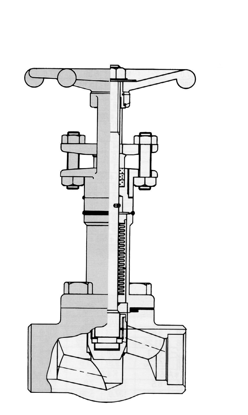
• Reduce monitoring costs
• Hardfaced seating surface - Stellite 6 for long life
• Valve designed, manufactured and tested
- To ANSI B16.34/API 602 & 598
• Additional alloy and trims available
• For applications where leakage into or out of the valve is unacceptable
Heat transfer oil
OVERVIEW
• ASME B16.34 Design
• 15NB - 50NB (1/2 - 2”) Bolted Bonnet
• Flange Ends, SW, NPT, BSP or Buttweld ends available 150 to 2500 Class
• Design - API 602, BS 5352, MSS SP11, ANSI/ASME B16.34
• End Connections Socket Weld - ANSI/ASME B16.11
Thread - ANSI/ASME B1.20.1
Butt Weld - ANSI/ASME B16.25
Flange - ANSI/ASME B16.5
• Test and Inspection - API 598 / BS 5146
MATERIALS
* Stem Smoothness ≤ Ra 0.80 µm
** Stuffing Box Smoothness ≤ Ra 3.2 µm
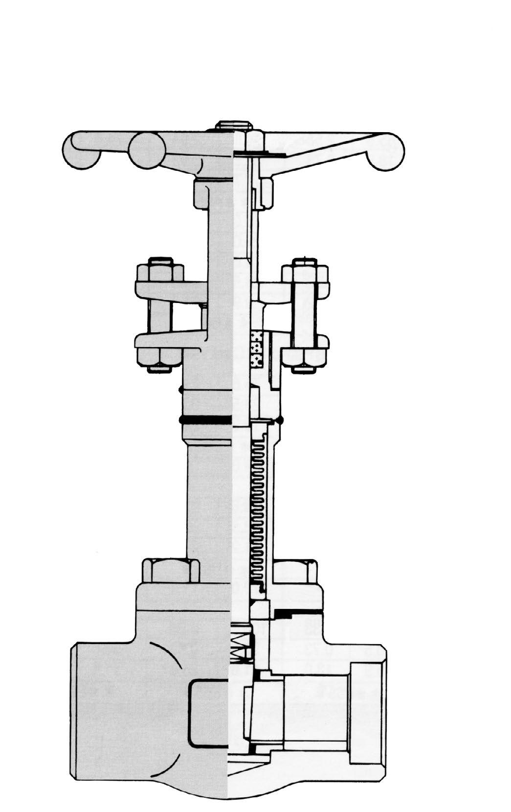
• Inconel or 321SS
- For longer
- Maximum
• Flanged, screwed or welded end connections
• Welded or bolted bonnet design
• Zero stem leakage
- Eliminates media loss
- Satisfies environmental regulations
• Zero maintenance
- Lower operating costs/no downtime
• Three stem seals for safety
- Metallic bellows
- Graphite packing
- Backseat in open position
• Reduce monitoring costs
• Hardfaced seating surface - Stellite 6 for long life
• Valve designed, manufactured and tested
- To ANSI B16.34/API 602 & 598
• Additional alloy and trims available
• For applications where leakage into or out of the valve is unacceptable
- Heat transfer oil
- Toxic fluids
- Steam - Regulated media DESIGN FEATURES
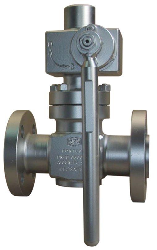
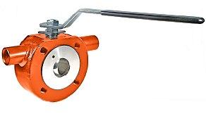
FEATURES
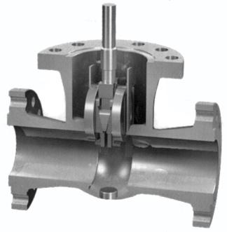
• Wafer jacketed ball valve
• Jacket connections - threaded, flanged, oversized (on request).
• Oversized and /or special jackets in carbon and stainless steel.
• Adjustable packing gland.
• Also available in 150 to 600 class
• Bottom-loaded blow-out proof stem.
• Low operating torque to reduce automation costs.
• Optional mounting pad complied with ISO 5211 for ease and interchangeability of actuation.
• Tested according to MSS SP-110/API 598.
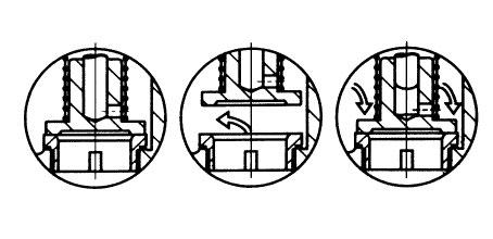
HEATING JACKET FLANGE CONNECTION
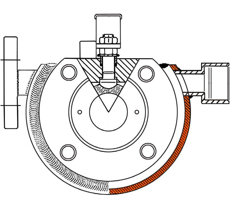
HEATING JACKET THREADED CONNECTION
HEATING CHAMBER JACKET
* Or Stainless Steel on request.

DIMENSIONS 150 & 300 CLASS
“Australian Pipeline Valve produces isolation, control and flow reversal protection products for severe and critical service media in utility, steam, pipelines, oil & gas and process industries. APV valves and pipeline products form the most competitive portfolio in the market.”