SAFETY INFORMATION
The following general safety information should be taken in account in addition to the specific warnings and cautions specified in this manual. They are recommended precautions that must be understood and applied during operation and maintenance of the equipment covered in this I.O.M.
• Gearbox surface temperature may be dangerously too hot or too cold for skin contact.
• Ensure adequate ventilation is available for service.
This manual provides instructions for storing, general servicing, installation and removal of gearboxes.
APV and it’s resellers refuse any liability for damage to people, property or plant as well as loss of production and loss of income under any circumstances but especially if caused by: Incorrect installation or utilisation of the gearbox or if the gearbox installed is not fit for intended purpose. It is the sole responsibility of the user to ensure the gearbox type and materials are correctly specified.
DURING OPERATION TAKE INTO ACCOUNT THE FOLLOWING WARNINGS:
a- The gearboxes internal parts shall be handled with care avoiding scratches or surface damage.
b- All tools and equipment for handling the internal parts shall be soft coated.
c- Gearboxes can be fitted with seals in Buna, Viton, etc., hence high temperatures will damage sealing components.
For all operations make reference to position number on part list of the applicable drawing listed.
Personal injury may result from sudden release of any process pressure. APV recommends the use of protective clothing, gloves and eye wear when performing any installation or maintenance.
Isolate the valve from the system and relieve pressure prior to performing maintenance.
Disconnect any operating line providing air pressure, control signals or electrical power to actuators.
If a gasket seal is disturbed while removing or adjusting gasketed parts, APV recommends installing a new gasket while reassembling. A proper seal is required to ensure optimum operation.
Australian Pipeline Valve - Installation, Operation and Maintenance Manual 3 MANUAL OVERRIDE GEARBOX - SERIES MO
Potential HIGH PRESSURE vessel - be aware of high-pressure hazards associated with the attached valve or other actuated device when installing or performing maintenance on the operator. Do not remove the operator bolts from the valve or actuated device unless the valve or device stem is secured or there is no pressure in the line.
For maintenance and/or disassembly of the operator when installed on the valve, ensure that the operator is not under thrust or torque load. If the valve must be left in service, the valve stem must be locked in such a way as to prevent any movement of the valve stem.
Do not manually operate the operator with devices other than the installed handwheel. Using force beyond the ratings of the operator and/or using additive force devices such as cheater bars, wheel wrenches, pipe wrenches, or other devices on the operator handwheel may cause serious personal injury and/or damage to the operator and valve.
Do not exceed any design limitations or make modifications to this equipment without first consulting us.
Use of the product must be suspended any time it fails to operate properly. Standard gearboxes are not suitable for motor actuation. A special heavy duty version can be specified for this purpose.
Do not use replacement parts that are not genuine Diamond Gear parts, as serious personal injury and/or damage to the operator and valve may result.
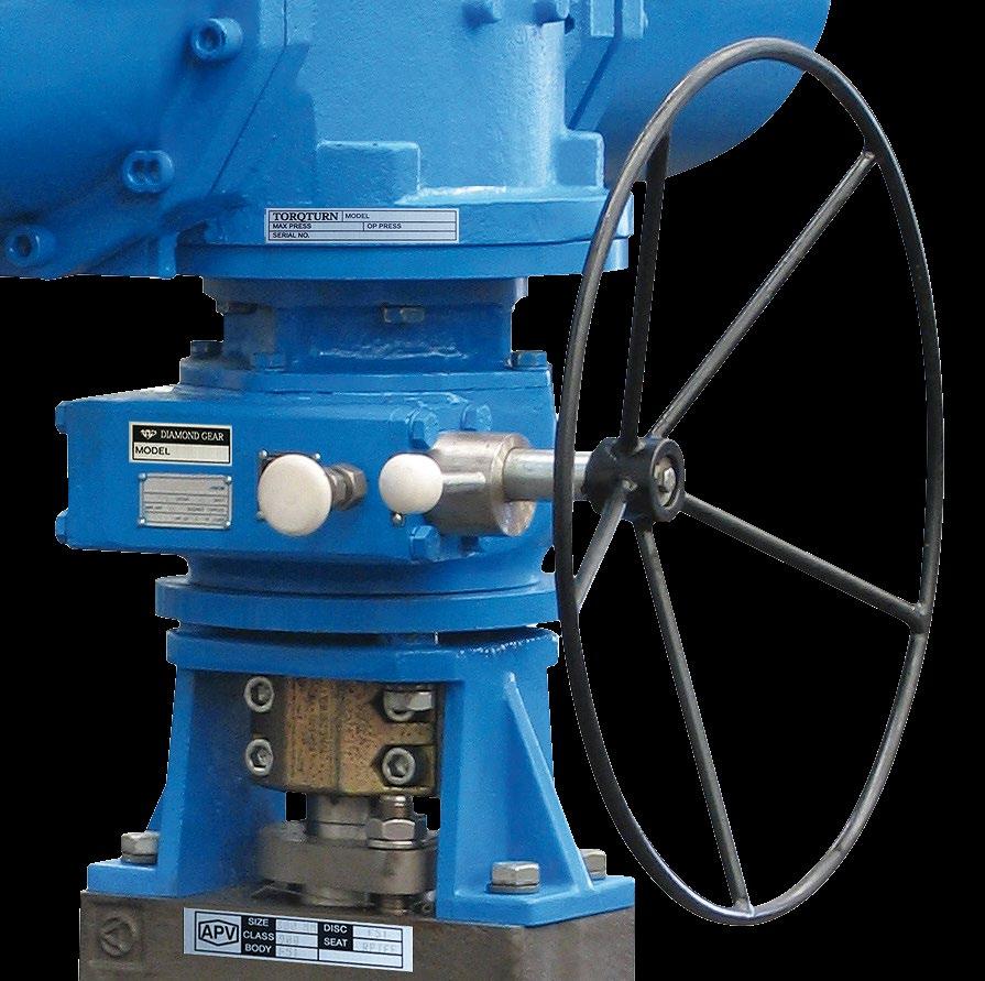
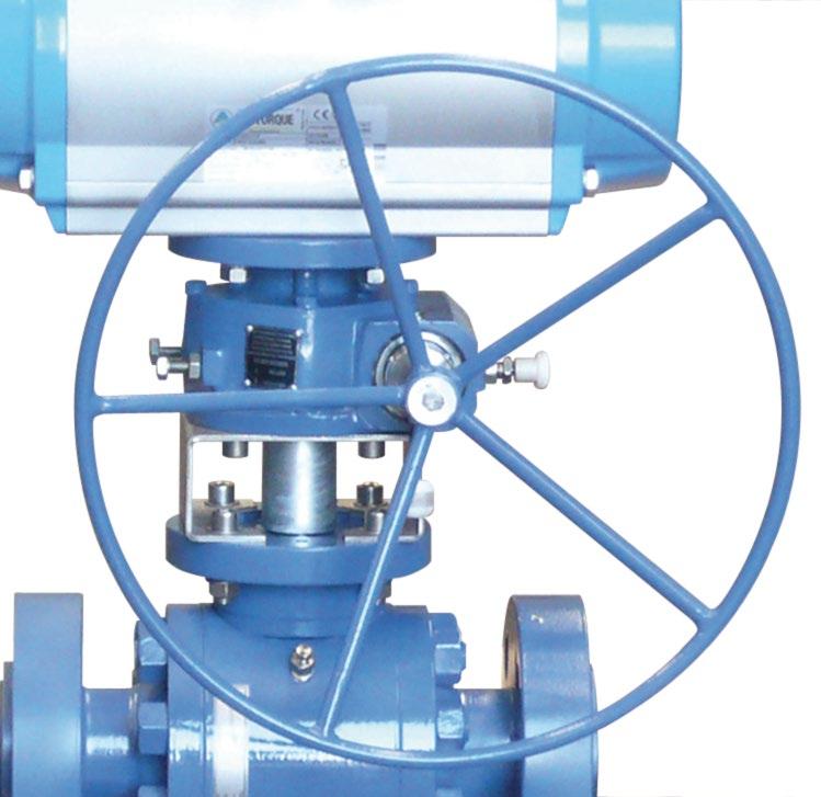
1.0 DESCRIPTION
The Diamond Gear MO series declutchable gear operators offer simple and reliable manual positioning of valves, dampers and other quarter turn devices when over-riding exiting pneumatic or hydraulic rotary actuators. All Diamond Gear MO units combine rugged construction, light weight and modular design to provide the most efficient and most cost effective solution to a full range of manual override requirements. The self locking SGI/Bronze or steel worm gear design means safe and easy operation, positive manual positioning and extremely long life the MO can be adapted to any quarter turn actuator and may even be installed in the field on existing valves.
Gear operators should be sized with at least a 40% safety factor or even more if high or low temperature or dirty service or infrequent use. Valves should be regularly opened to avoid sticking. Most valves will increase in torque over time as debris, corrosion, increased pressure, erosion, infrequent use, sticking of seats, etc., all effect torque. Bear in mind, some valves like plug valves need regular lubrication. Also the theorectical torque of a valve can be dramatically different to the actual torque.
MANUAL OVERRIDE GEARBOX - SERIES MO Australian Pipeline Valve - Installation, Operation and Maintenance Manual 4
2.0 SPECIAL FEATURES
Stroke Adjustment: 10° at each end, clutch arrangement for engagement and disengagement. Possibility or provision of handwheel at either end of worm shaft. Please refer to drawing for more information.
3.0 STORAGE
MO Gear Operators don’t have a shelf life however, store in a clean, dry area protecting the input and output bores from corrosion and damage by sealing each unit in a plastic bag.
Store on wooden skids to protect the machined mounting flange. If the operators must be stored outside, they must be covered in polyethylene with silica gel crystals to absorb moisture. Input shafts should be rotated every three months to mix lubricant.
4.0 OPERATION
Normal operation is with the selector-lever in the ‘OFF’ position. In this mode, the worm & worm wheel are disengaged and the actuator is free to operate the valve. When ‘ON’ mark on the indicator plate is aligned with the arrow mark on the label plate. Operation of the wheel will actuate the process valve. In case of aligning of ‘OFF’ mark, the wheel will move the spindle of the manual override freely as the unit would be declutched.
Valve/Actuator/Gear Operator Engagement
Valve, actuator and segment gear are always permanently engaged when assembled. The clutch DOES NOT disconnect the actuator from the valve.
Clutch Lever Mechanism
Clutch Lever engages or disengages the worm gear with the segment gear, so that the segment gear spins freely. The gear operator travel stops limit the travel of the segment gear, thereby limiting rotation of the whole actuator/valve assembly.
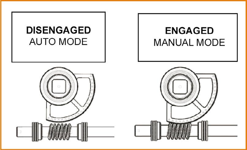
To engage manual operation, first pull out the spring loaded locking pin, then rotate the clutch lever clockwise until the locking pin re-engages. Anti-clockwise lever movement disengages manual operation and returns the system to automatic operation. Instructions given on the label plate should be
Australian Pipeline Valve - Installation, Operation and Maintenance Manual 5 MANUAL OVERRIDE GEARBOX - SERIES MO
followed.
If the turning of the clutch lever happens to be tight, turn the handwheel a little to make the clutch lever movement free.
The manual override also has a limit Stop arrangement by which it is possible to control the stroke by ±10° from either open or closed range. This can be achieved by adjusting the two stroke limiting screws to the extent desired. For normal operation of the valve, ensure the screws to be set in the extreme out position.
Note, When under normal control the valve remains locked in the last set position.
4.1 INTEGRATED BLOCK & BLEED AIR TUBING OPTION
Optional block & bleed valve triggered but the clutching mechanism is a recommended option to avoid gearbox damage due to operator error. If using a separate block & bleed device, please follow manufacturer’s instructions.
Air tubing from integrated block & bleed valve to actuator air ports should be as follows. If not using, leave ports unplugged or install dust screens/filters. Integral design shown. Separate limit switch box c/w seat limit switch box is fitted depending on model.
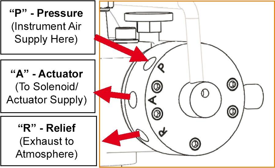
Note: Filter/regulator is recommended to ensure clean, dry air is supplied to block & bleed valve and actuator.
5.0 INSTALLATION
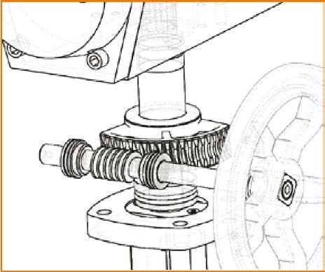
The MO unit is installed by sandwiching them between the valve and actuator. The drive sleeve of the MO accepts the valve shaft on one end and the actuator drive adapter from the other end. The bottom flange of the MO is bolted to the valve flange and the top flange of the MO is bolted to the base pad of the actuator. Install as follows:
a) Check the coupling pin dimensions and ensure they match with the gear unit being installed in the system.
b) Bring the valve and the pneumatic actuator to the intermediate position.
c) Position of gear unit ‘OFF’ (i.e. ‘Pneumatic’ mode, where the gear unit is disengaged) by pulling out the
MANUAL OVERRIDE GEARBOX - SERIES MO Australian Pipeline Valve - Installation, Operation and Maintenance Manual 6
locking assembly pin & bringing the unit to ‘OFF’ position by rotating the selector lever.
d) Assemble the valve, gear unit and pneumatic actuator firmly in position.
e) Bring the gear unit to ‘ON’ position (i.e. ‘Manual’ mode, where the gear unit is engaged) by reversing the sequence explained in point (c) above.
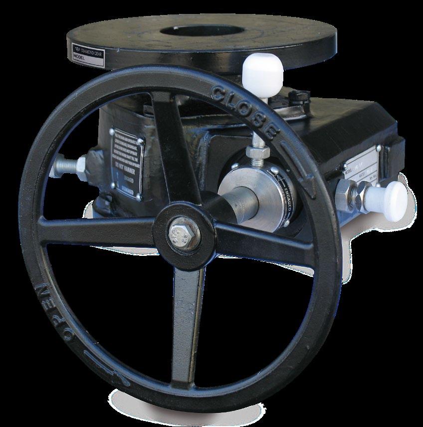
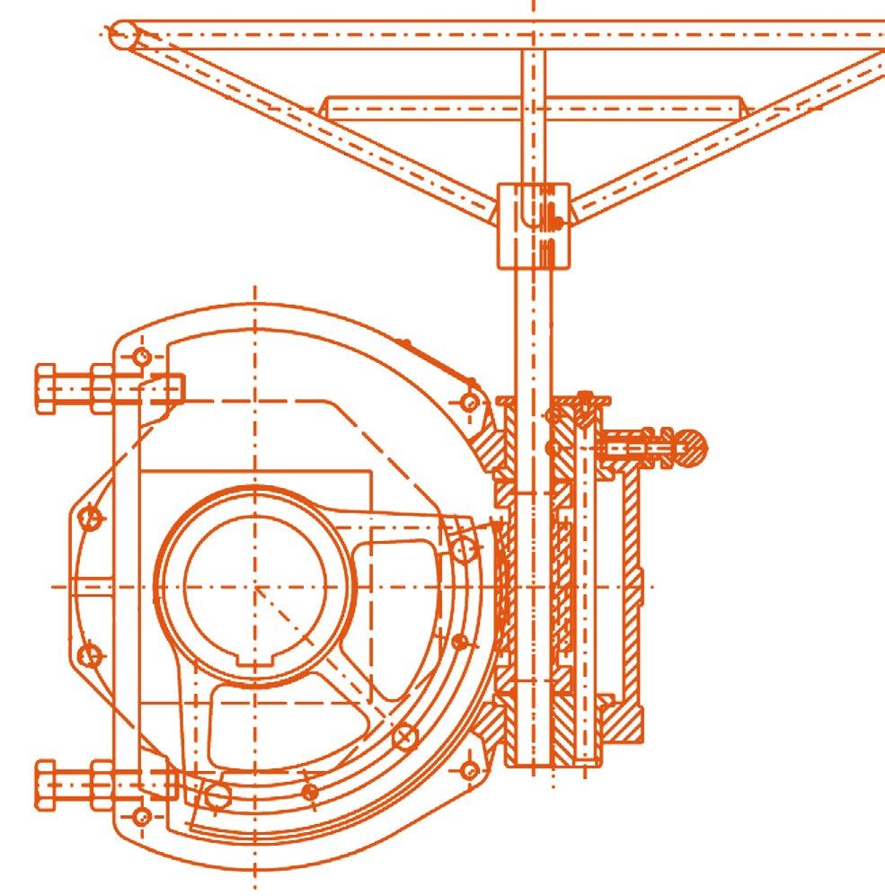
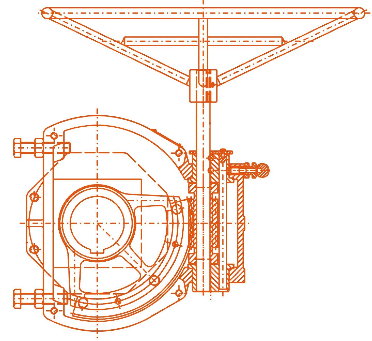
*
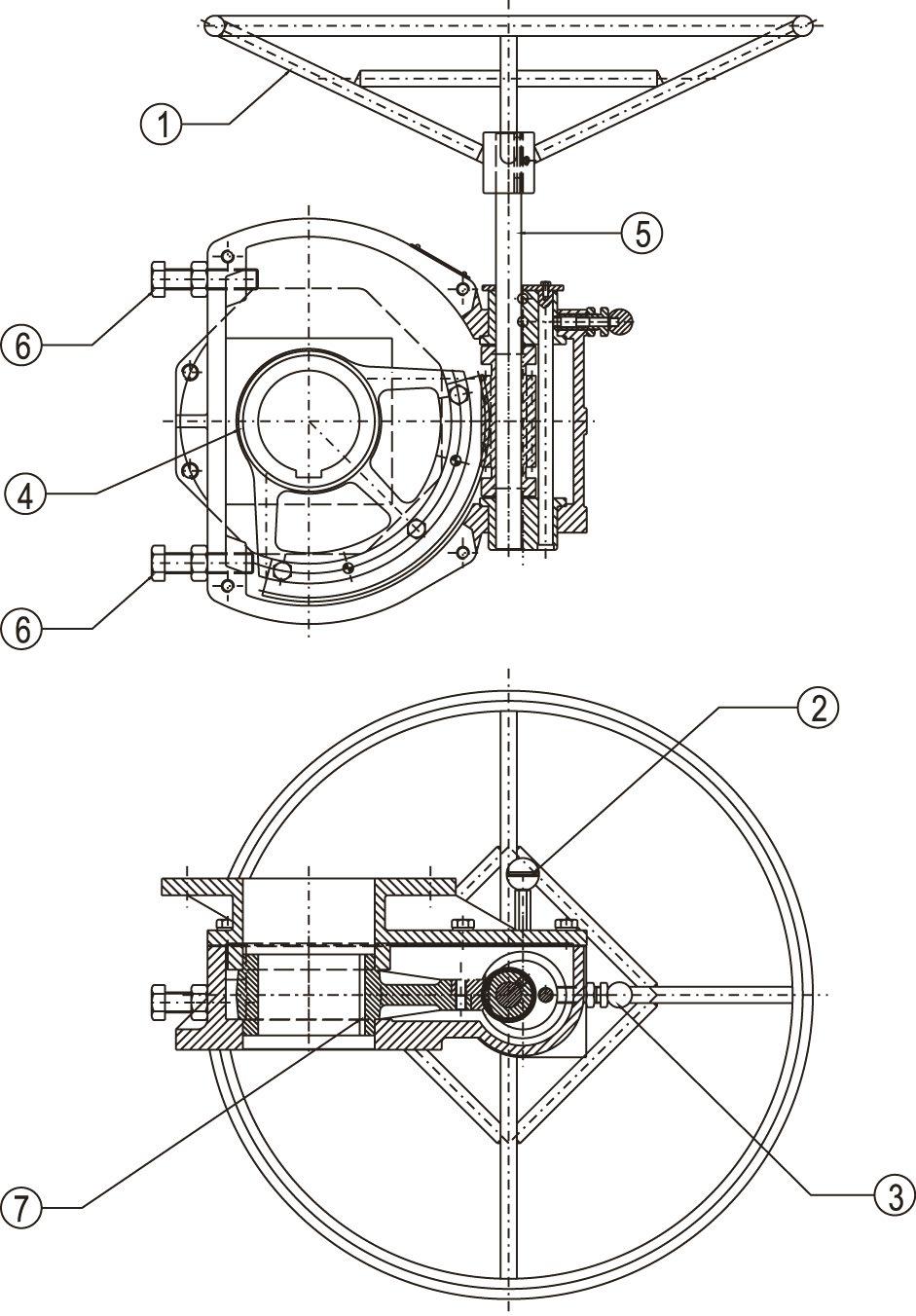
1. HAND WHEEL
2. LOCKING PIN
3. CLUTCH LEVER*
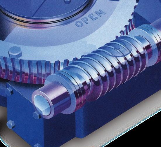
4. WORM WHEEL
5. WORM SHAFT
6. LIMIT STOP ARRANGEMENT
7. DRIVE SLEEVE
* Can be handle bar in some sizes
Indicative drawing only, refer to as-built drawing, design varies depending on size, materials and mounting option specified.
Keep the equalising valve in the “OPEN” position for manual operation (rotate the knob anti-clockwise direction to open) and “CLOSE” position for auto mode (rotate knob in clockwise direction to close).
Never operate manual overrides beyond adjusted stroke of actuators fitted with limit stop screws. Stop Rotation of handwheels when rotation becomes hard. Never use extra leverage to operate handwheels.
5.1 SETTING ADJUSTMENT SCREWS
1. Move the valve to the fully closed position. Set the adjustment screw (6) clockwise until it makes contact with the segment in the gear then lock the adjustment screw in place with the lock nut.
2. Move the valve to the fully open position.
Note: If the valve is installed in the line and you cannot see if the valve is full open, count the number of turns of the handwheel required to reach 90 degrees. For example, if the gear box is a 100:1 ratio,
Australian Pipeline Valve - Installation, Operation and Maintenance Manual 7 MANUAL OVERRIDE GEARBOX - SERIES MO
rotate the handwheel 25 times to reach 90 degrees. This can still be inaccurate and it is recommended to remove the valve from the line and properly calibrate the operator at the next opportunity.
3. Set the other adjustment screw clockwise until it makes contact with the segment inside the gear. Lock the adjustment screw with the lock.
Do not use oversize handwheels or leverage/cheater bars. This can result in damage to the gear box.
Note
Do not operate actuator whilst manual over-ride engaged
Torque Sizing Guidelines
• Size gear operators at 5%-10% below rated Max Output Torque
• Use highest expected valve torque value
• For spring return applications, add actuator spring torque plus valve torque (gear operator must overcome valve torque plug spring force)
6.0 MAINTENANCE
Gearboxes are factory pre-greased for life depending on the environment and service, for water resistant service. Inspect the internal gears and bearings annually and re-lubricate where required. Obviously for special, critical or frequent service applications, inspect the internals more regularly. To inspect the internals, remove cover bolts.
Complete overhaul or extra ordinary repairs should be sent back to APV. However, it is usually cheaper to replace the unit with a brand new operator.
Should extra lubricant be required, use suitable multipurpose grease containing ‘EP’ additive that is non separating and contains no additive that will damage Viton or Buna O-rings.
MANUAL OVERRIDE GEARBOX - SERIES MO Australian Pipeline Valve - Installation, Operation and Maintenance Manual 8
7.0 TROUBLESHOOTING
SL NO.FAULT
1. Valve not opening/ closing even when handwheel is rotated
2. Clutch lever not rotating/ getting engaged
3. Full open/ closing of valve not achieved/ obtained
4. Valve opening/ closing found to be more than 90º, Over closing/ over opening
5. Excessive force required for handwheel rotation
PROBABLE CAUSE REMEDIAL ACTION
Clutch lever not engaged properly
Worm to shaft locking pin broken due to over loading.
Handwheel to shaft locking failed, key sheared/ missing.
Broken locking pin.
Broken clutch lever
Bent worm shaft due to excess loading.
Improper adjustment of limit stop screw on MO
Fixing bolts between valve and MO loose. Play between the joint
Excessive play in adaptor linkage/ keyway
Improper adjustment of limit stop screws.
Excessive valve torque. MO not selected properly
Trapped air inside Actuator chamber.
Engage clutch properly by shifting clutch lever to manual position (ON). See instruction label on Actuator
Open gear box and replace locking pin/ grub screws
Check handwheel to shaft joint and replace key/ pin if broken.
Open gear box, remove broken piece, fit fresh locking pin.
Replace broken piece and fit fresh lever on gear box
Open check worm shaft. Replace, if bent or damaged
Re-adjust limit stop screws and lock in position.
Check mounting bewteen valve and MO. Tighten nuts after aliging in correct position.
Check linkage between valve and shaft and gear box. Replace key, if required.
Loosen locknuts. Adjust stopper screws to the desired opening/ closing and tighten locknuts.
Check valve torque and replace with higher size MO, if required.
Open equalising valve, if provided. Provide equalising valve if not provided already for DA Actuators.
Australian Pipeline Valve - Installation, Operation and Maintenance Manual 9 MANUAL OVERRIDE GEARBOX - SERIES MO

www.australianpipelinevalve.com.au AUSTRALIAN PIPELINE VALVE® HEAD OFFICE 70-78 Stanbel Road Salisbury Plain South Australia 5109 Telephone +61 (0)8 8285 0033 email: admin@australianpipelinevalve.com.au If you have any requirements in the field of valves, please contact us for a prompt response. Continuous development of Australian Pipeline Valve products may necessitate changes in the design or manufacture process. Australian Pipeline Valve reserves the right to effect any such changes without prior notice. © Australian Pipeline Valve 1990 - 2024 Edition LOCAL DISTRIBUTOR/AGENT IOM Diamond Gear Override