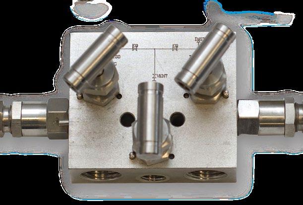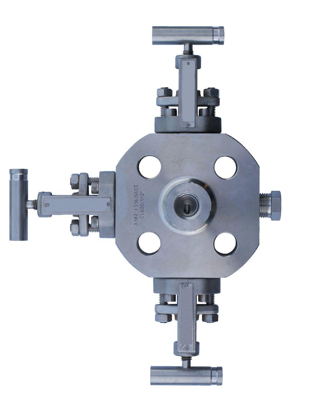


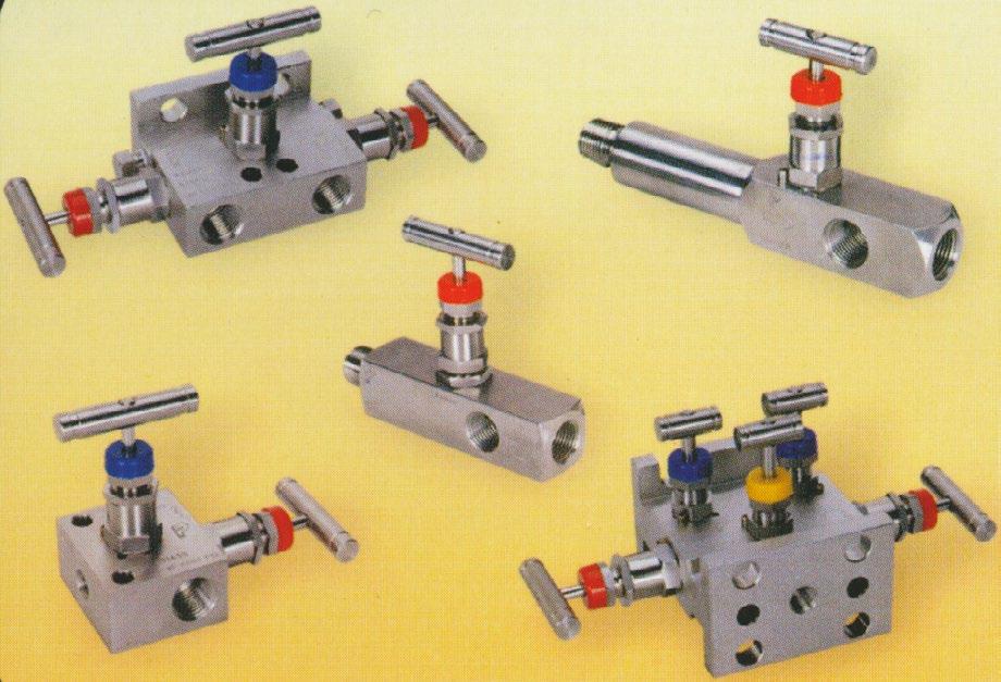
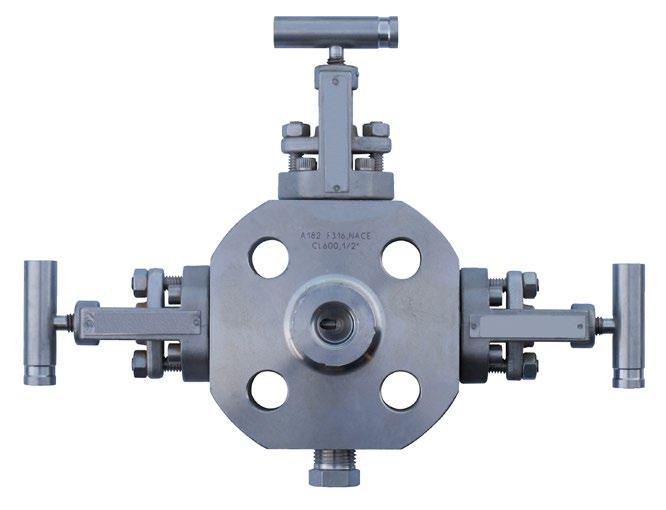
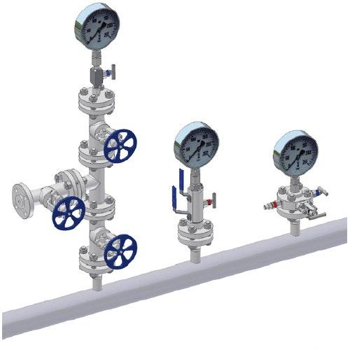
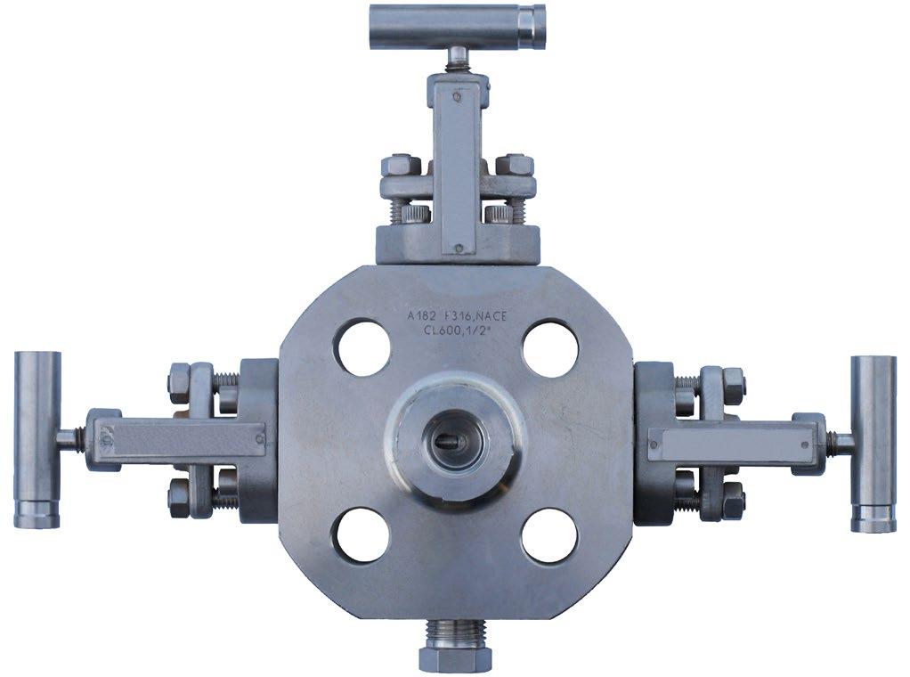
Flowturn offers a variety of 2, 3 and 5 valve instrument manifolds.
The 2 valves manifolds are designed for static pressure and liquid level application; the 3 and 5 valve manifolds are designed for differential pressure appplications.
FEATURES
• Convenient method of blocking, bleeding, and calibrating pressure instruments.
• Designed for connected system impulse line & transmitter.
• Combines the function of a tee, calibration valve, isolation valve, all tubing and fittings in a single valve configuration.
• Bonnet stopper prevents accidental movement.
• Free swiveling ball end stem (metal seat, standard.) assures bubbles tight valve closure without seat galling.
• Special hardened ball seat is ideal for both gas and liquid service.
• All stem packing is located below the stem threads preventing galling, corrosion and contamination.
• Adjustable packing reduces the possibility of bonnet/body leaks.
• Full back sealed bonnets prevents accidental stem removal and blowout.
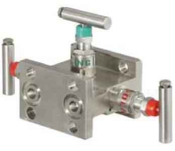
The Flowturn range of Manifolds offer a safe and economical method of installation to control and measure pressure of liquids and gaseous media. They are ruggedly manufactured and precision machined to the most exacting dimensional tolerance to ensure perfect installation and application.
Flowturn Manifolds are functionally installed to control, measure, isolate, equalise, calibrate, drain, vent or differentiate the pressure of liquids and gases.
Flowturn Manifold series offer optional 2, 3 and 5 valve configurations which come in remote mounting (pipe to pipe), direct mounting (pipe to flange, flange to flange) onto the instrument on a 2 1/8” (54mm) centre. Working Pressure up to 6000 PSI.
• Working pressure up to 6000 psig (413 bar).
• Temperature up to 450°F (232°C) with PTFE packing up to 1200°F (648°C) with Grafoil® packing.
• Orifice Size - 0.156 inch (4.0 mm).
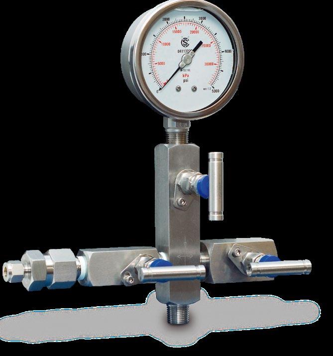
• For block and bleed (or calibration) of a gauge or absolute pressure transmitter or gauge.
• Consists of equalizing, isolation and vent.
• Direct instrument mount and remote mount.
• End connections pipe or flange.
APPLICATIONS
• General plant service.
• Pressure instrumentation devices.
• Differential pressure instruments devices.
• Pressure equalization.
• Block and bleed applications.
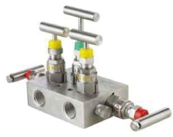
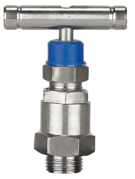
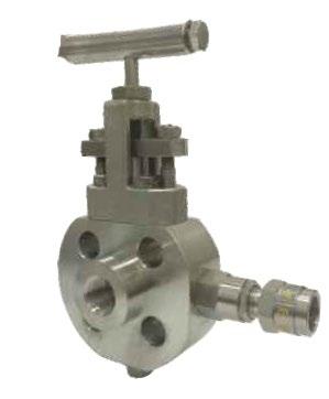
T-TYPE SINGLE
(SINGLE FLANGE, PIPE TO FLANGE)
Manifolds bolt directly to the differential pressure Instruments which eliminate the need for unnecessary piping, valves and fittings. T-Type manifolds come complete with mounting kit for quick and easy installation to a pipe stand.
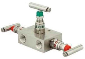
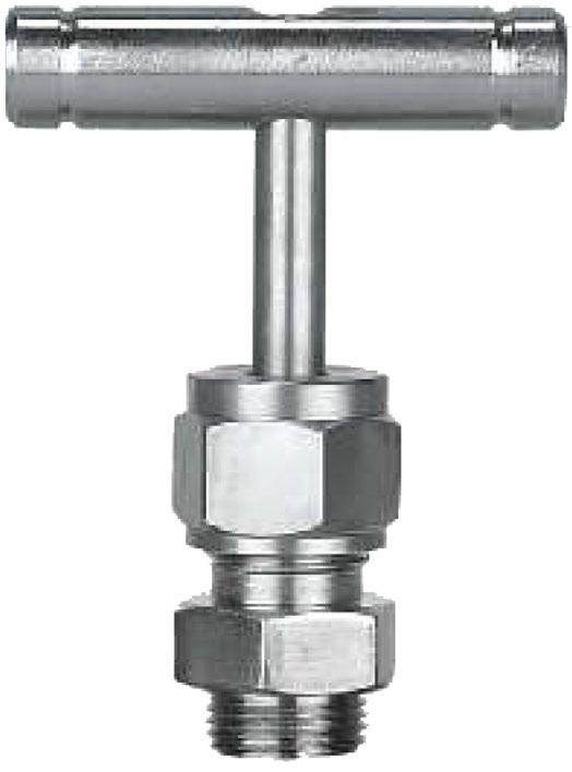
R-TYPE (PIPE TO PIPE IN-LINE)
Manifolds are designed for differential pressure of flowrecorder to impulse tubing. Connections are 1/2” NPT industry standard and 2 1/8” (54mm) centre dimension (Model for 2 3/16” & 21/4” dimension) (Model for 2 3/16” & 21/4”- centre dimension).
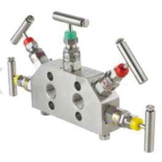
H-TYPE (DUAL FLANGE, FLANGE TO FLANGE)
Manifolds bolt directly to the differential pressure instruments which eliminate the need for unnecessary piping, valves and fittings.
Flowturn supply quality precision valves for each application.
As well as hand valves, Flowturn can produce monoflange double block and bleed integral manifolds.
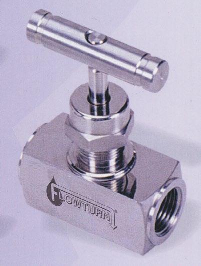
Flowturn’s hand valve and gauge valves include multi-port and block and bleed styles suitable for gauge isolation, calibration and venting with a choice of either globe pattern or through bore designs. A wide choice of end connections and comprehensive range of standard gauge accessories allows complete flexibility for individual installations.
SPECIFICATIONS
Materials CS, SS, Duplex and other exotic materials.
Seats Metal (and soft)
Orifice Size 1/8 inch (3mm) to 5/8 inch (16mm).
Pressure (max) 10,000psig [690 bar]
Temperature (max) 1000OF [538OC]

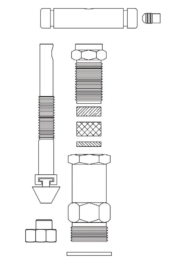
FEATURES
ROLLED STEM THREADS
BACK SEAT DESIGN
BODY MATERIAL
Available in 316SS, carbon steel with yellow or plain zinc plated.
VARIETY OF THREADED CONNECTIONS
Choice of NPT, BSPT or TUBE.
Male - Male
Male - Female
Female - Female
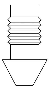
NON-ROTATING BALL OR CONICAL ‘V’ STEM TIP
Providing an excellent seal between the seat and stem tip without galling.
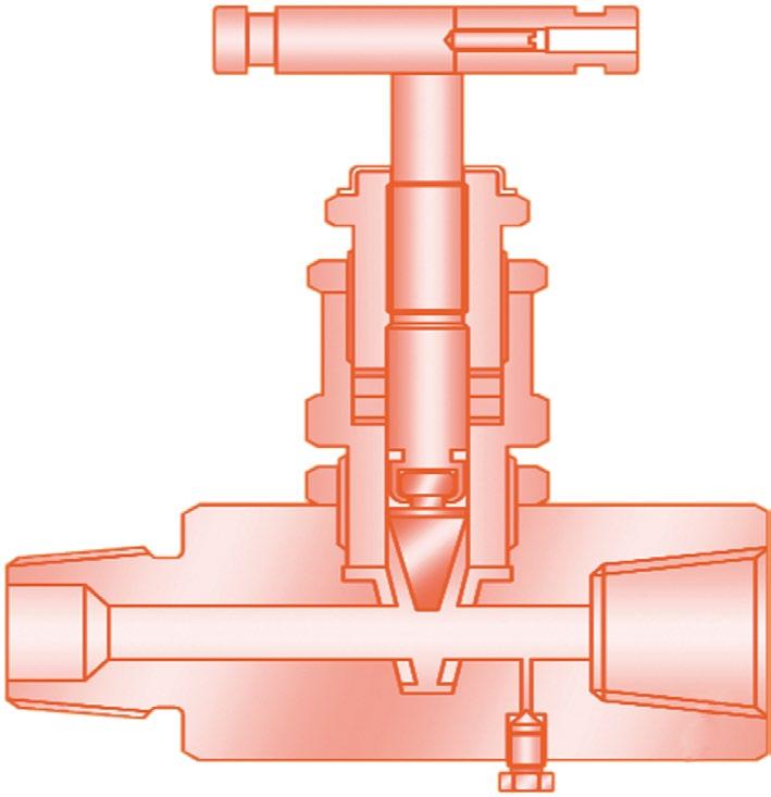
*S-M9 has integral bleed plug
HANDLE
Standard with tee bar handles.
1/2” to 1” Style Shown
MODEL S-H7/H71-PM
1/8” to 3/8” Style Shown
DUST CAP (PTFE PACKED ONLY)
Keeps external contamination out of thread area.
MIRROR FINISH STEM
Burnished to 16 RMS.
REINFORCED GLAND PACKAGE
Eliminating potential leakage.
SEALING AREA BELOW STEM THREAD
Protecting the thread from contamination by process media.
BONNET STOPPER
Preventing accidental emission.
METAL TO METAL SEAT
Serving the working conditions of high pressure and temperature. Integral hard seat. Soft seat also available in plug type straight through style.
OPTIONAL PANEL MOUNT NUTS
FEATURES
ROLLED STEM THREADS
BACK SEAT DESIGN
BODY MATERIAL
Available in 316SS, carbon steel with yellow or plain zinc plated.
VARIETY OF THREADED CONNECTIONS
Choice of NPT, BSPT or TUBE.
Male - Male
Male - Female
Female - Female
NON-ROTATING RISING PLUG
Providing an excellent seal between the seat and plug.
*S-M9S has integral bleed plug See below.
HANDLE
Standard with tee bar handles.
DUST CAP (PTFE PACKED ONLY) Keeps external contamination out of thread area.
MIRROR FINISH STEM
Burnished to 16 RMS.
REINFORCED GLAND PACKAGE
Eliminating potential leakage.
SEALING AREA BELOW STEM THREAD
Protecting the thread from contamination by process media.
BODY TO BONNET METAL SEAT
BUBBLE TIGHT SHUT OFF Soft Delrin or PTFE seat.
1/8” to 3/8” Style Shown 1/2” to 1” Style Shown
INTEGRAL BLEED
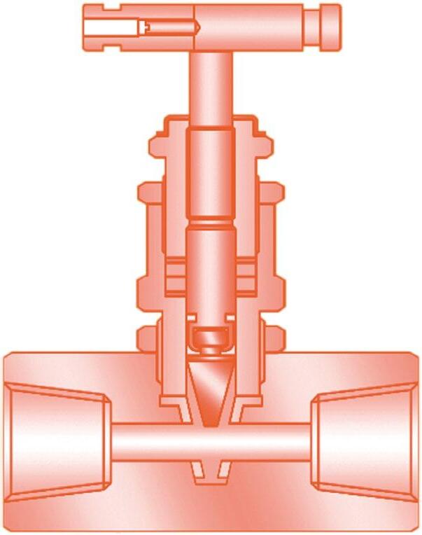
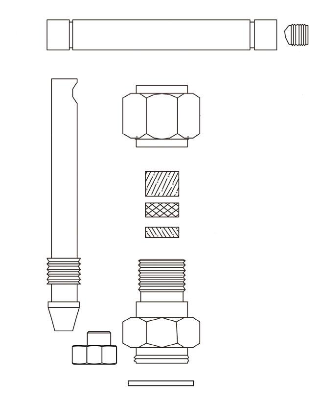
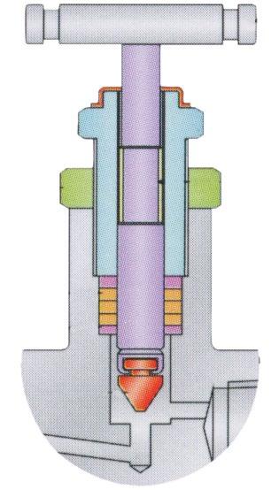
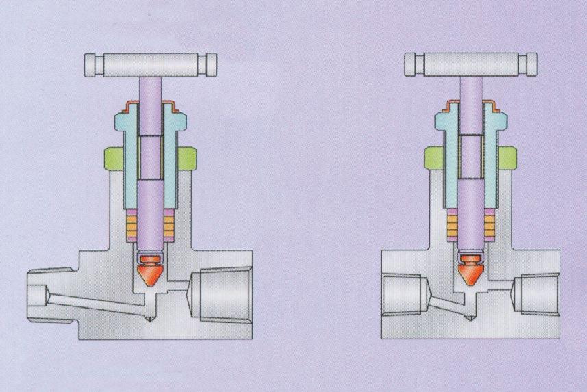
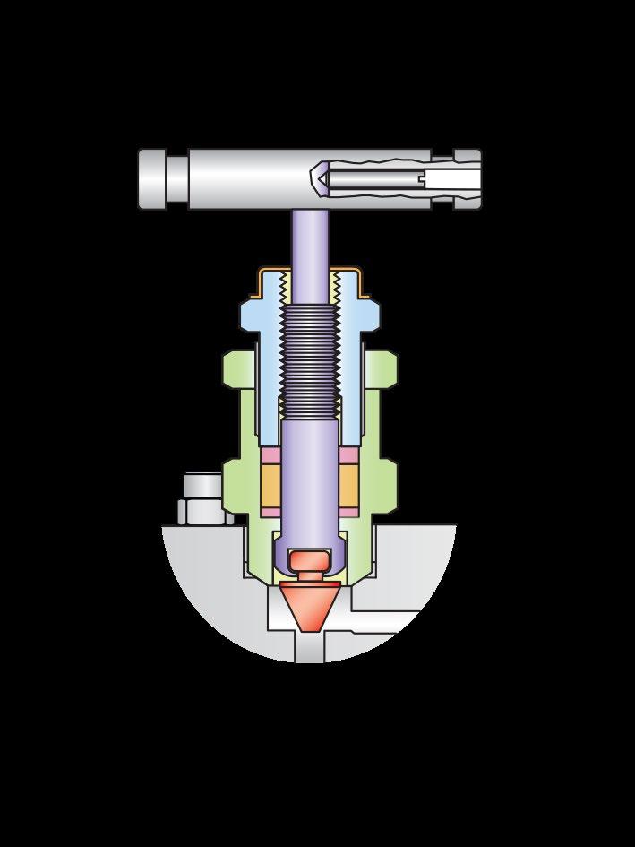
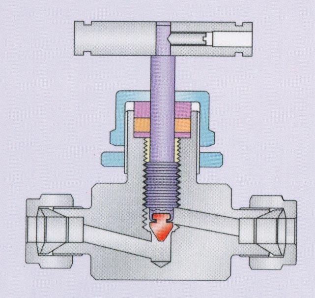
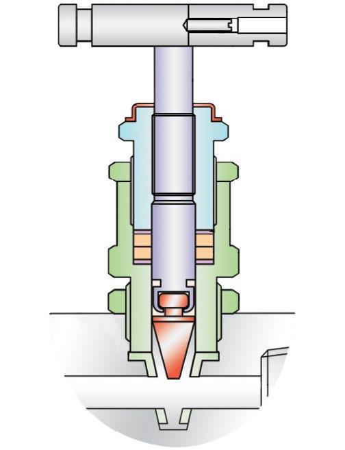
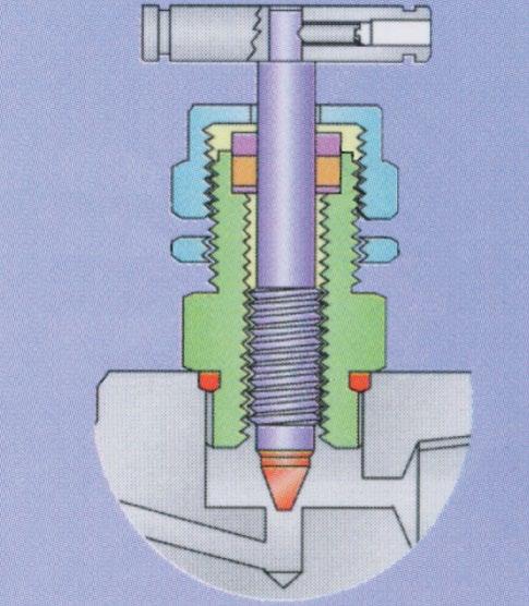
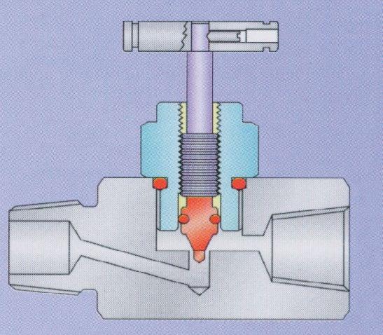
DESIGN OVERVIEW
ROTATING

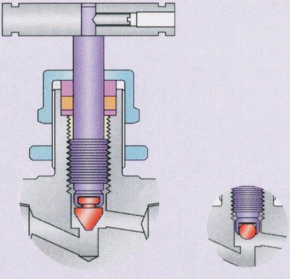
One piece bar stock construction with full material traceability. Back seating of stems in a fully open position prevents stem back out. All types of valves have self centring, non rotating needle on the valve seat, alternative seating to choose for every application requiring bubble tight shut off. Safety Stop Pin, 316 stainless steel stopper prevents detachment of the bonnet from the body due to vibration.
Stainless steel models of needle, gauge and instrument manifold valves, equipped with needle stems, meet NACE MR-01-75.
Bonnet-to-body-seat, metal-to-metal seal eliminates the need for O-ring seals.
Shroud with colour identification -
Handle - T-bar metal (standard) or circular plastic optional.
Double bonnet or single bonnet (optional).
Optional high temperature packing for compatibility to 1000°F on certain models.
All valves are designed in accordance with ASME/ANSI B16.34-1988 and ASME Section VIII, Div 1.
Low torque operation.
Spindle treated for durable operation.
Stem Types
Taper Regulating Ball Soft Ball (only for NUH Series) 10,000 PSI
MODEL
SH1 - Rising Plug Straight Through Type 6000 PSI or 10000 PSI
SM5 - Multiport Gauge Valve Globe Type MxF 6000 PSI
SM5A - Multiport Gauge Valve Straight Through MxF 6000 PSI
SM5F - Multiport Gauge Valve Straight Through FxF 6000 PSI
SM5K - OS&Y Root Isolation Valves
SH7 - Globe Type 6000 PSI
S15K - Globe Type 15,000 PSI
SM9 - Integral Block & Bleed Gauge-Globe Type 6000 PSI
SM9S - Integral Block & Bleed Gauge-Straight Thru Type 6000PSI
SH5 - Miniature Globe Type 6000 PSI (Soft) 3000 PSI (Metal)
SMO - Monoflange Instrument Valve
SBB - Block & Bleed Valves
ALTERNATE PRESSURE SUFFIX
BLANK - 6000 PSI 3 - 3000 PSI
1 - 10,000 PSI 5 - 15,000 PSI
V - Teflon®
R - Viton® O-Ring with Teflon® or 316 backup ring
H - Graphoil®
E - Fugitive / Low emission Graphoil (or use FE suffix) H7 & M5 do use E
L - Low Temp. Viton - 46˚C or HNBR
PACKING SEAT
D - Delrin® I - Integral Metal N - Nylon
K - PCTFE / KELF V - Teflon® Z - Special
E - PEEK M - 316 Overlay
MATERIAL
C - CS (CAD or Zinc Plated) J - Hastelloy®
S - 316 SS W - 316L
M - Monel® 400 Z - Special
CONNECTIONS INLET x Outlet †
2 - 1/4 -inch NPTF x 1/4 -inch NPTF
3 - 3/8 -inch NPTF x 3/8 -inch NPTF
22 - 1/4 -inch NPTM x 1/4 -inch NPTF
24 - 1/2 -inch NPTM x 1/4 -inch NPTF
33 - 3/8 -inch NPTM x 3/8 -inch NPTF
4 - 1/2 -inch NPTF x 1/2 -inch NPTF
4M - 1/2 -inch NPTM x 1/2 -inch NPTM
AT* - Tube Compression Fitting End(s)
44 - 1/2 -inch NPTM x 1/2 -inch NPTF
46 - 3/4 -inch NPTM x 1/2 -inch NPTF
48 - 1/2 -inch NPTM x 1 -inch NPTF
6 - 3/4 -inch NPTF x 3/4 -inch NPTF
66 - 3/4 -inch NPTM x 3/4 -inch NPTF
8 - 1-inch NPTF x 1-inch NPTF
88 - 1-inch NPTM x 1-inch NPTF ** - 1 1/4-inch to 2-inch
*Concatenate with size, example 4AT4 is 1/2 inch Tube x 1/2 inch NPTF, 4AT is 1/2 inch Tube x 1/2 inch Tube
† SH1 is Bi-Directional **32/40/50
SPECIAL SUFFIX FOR SH1/S-H7/S-H71 ONLY
Q - 1/2 inch & Over End connections (S-H1/S-H7/S-H71 ONLY)
BLANK- Under 1/2 inch End connections (Except 6.4mm Orifice 1/4 inch ~ 1/2 inch S-H1 see below.)
QR - 6.4mm Orifice 1/4 inch ~ 1/2 inch (S-H1 ONLY)
CONNECTION VARIATION SUFFIX
BLANK - No Variation
BSP - BSP
MSW - Male plain end (Male Socket Weld)(CS is black oxide coated)
SWF - Female Socket Weld
TB - Female Tube End
TC - Male Tube Stub End
BODY STYLE VARIATION SUFFIX
BLANK - Inline A- Angle
BONNET VARIATION SUFFIX
L - Integral Long body extension
BLANK- Threaded Bonnet (Standard) I - Integral Bonnet W - Welded Bonnet
B - Bolted Bonnet OS&Y O - OS&Y Bonnet Z - Special
OPTIONS
BL - Bonnet Lock Device
BS - Bellow Sealed
LT - Low Temp Lubricant (low temperature service -46˚C)
MO - Monel® Stem
OX - Oxygen Cleaning
PM - Panel Mount
RH - Black Round Handle
SG - (Sour Gas) meets NACE MR0175/ISO 15156-3 -2 (for Chloride
conditions ≤ 50 mg/l [ppm]) and NACE MR0103-2005 (316 SS only)
SG1 - (Sour Gas) meets NACE MR0175/ISO 15156-3 -2 (for Chloride conditions > 50 mg/l [ppm])
SV6 - Side Bleeder Fitted Type SV6
SVA - Side Bleeder Fitted Type SVA
BP - Bleed Plug
DB - Bleed Valve Bonnet
DBB - Two Bleed Valve Bonnets Z - Special
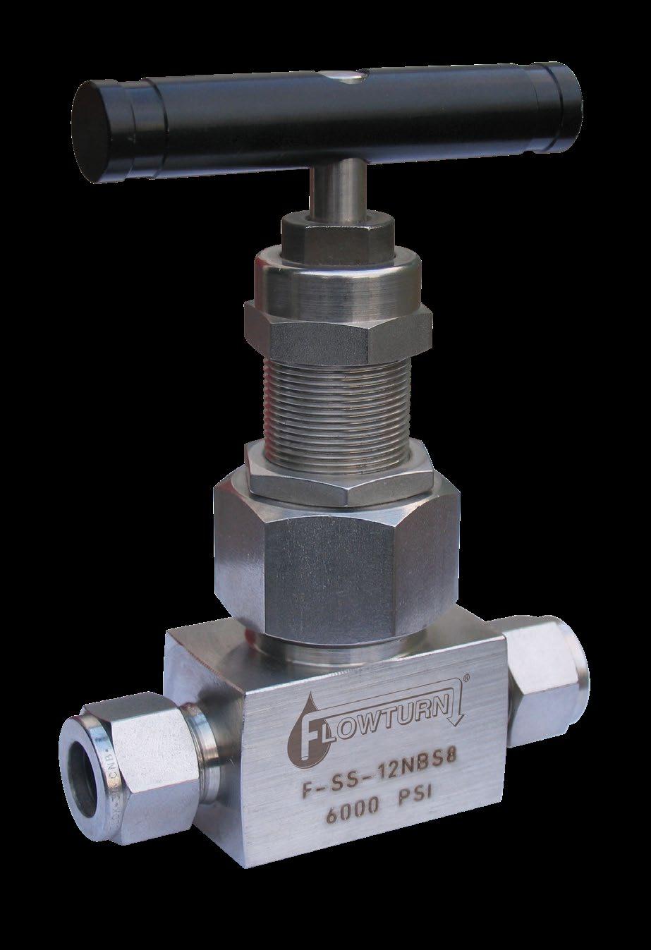
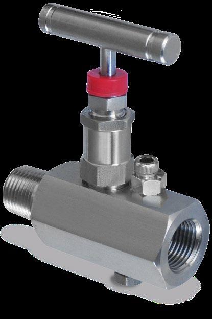
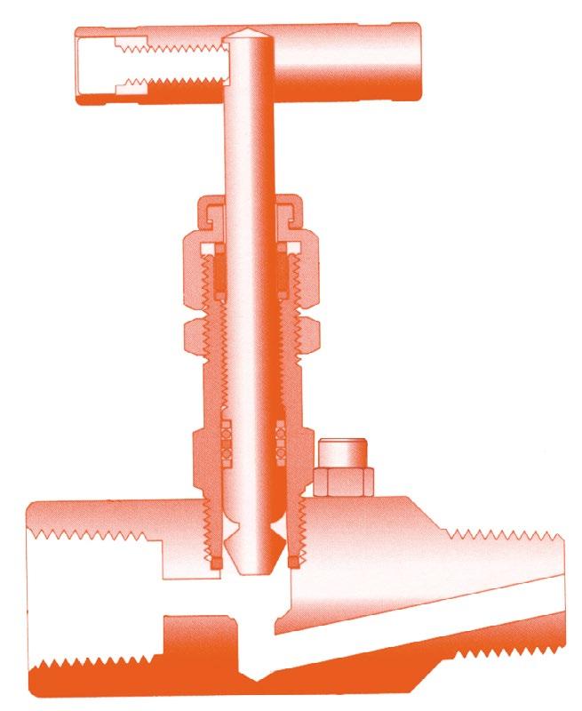
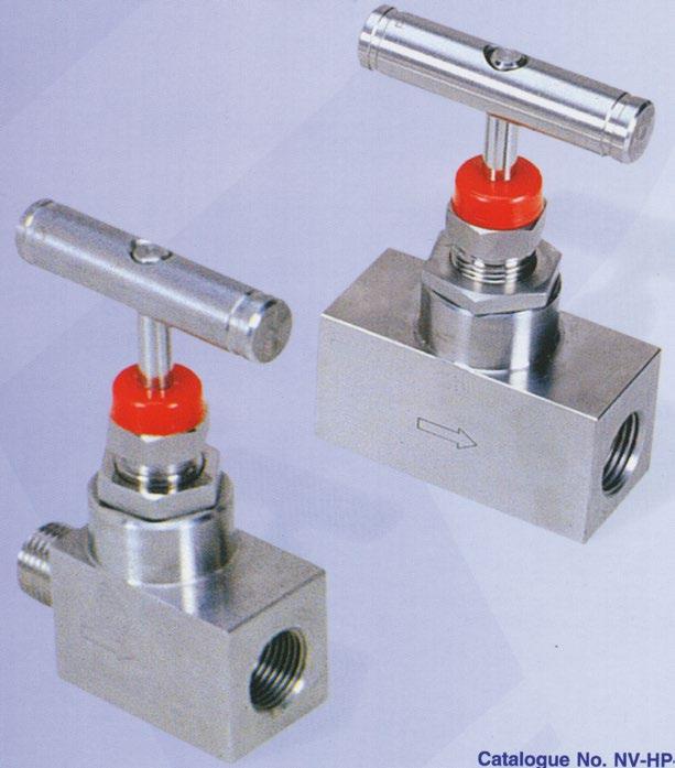
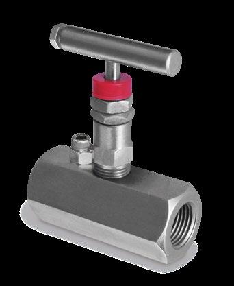
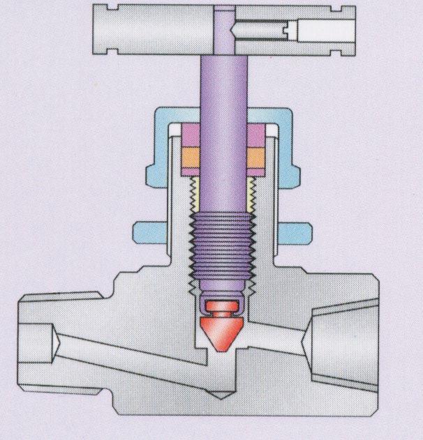
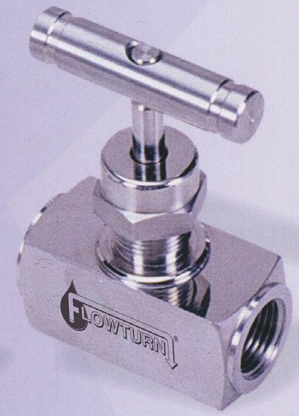
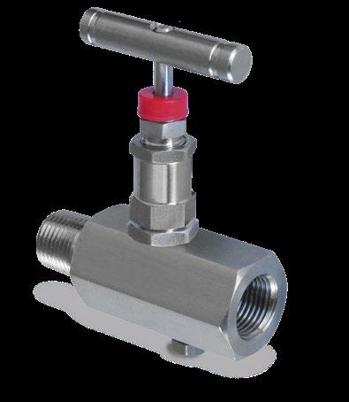
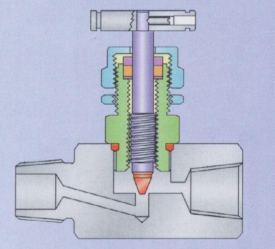
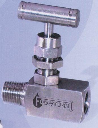
Flowturn ‘HP’ Series Globe Pattern Needle Valves are specially designed and ruggedly manufactured for use in corrosive and hazardous environments. ‘HP’ Series valves are used in process control, instrumentation and flow control applications. ‘HP’ Series valves are precision machined, and designed for durability and maximum efficiency to provide a high quality valve for use in fluid and gaseous control systems of different applications, to meet the exacting standards of our growing and demanding customers.
Flowturn ‘HP’ Series Valves are available in high grade stainless steel, carbon steel, monel and other materials in a variety of end connections including male / female threaded NPT, BSP, BSPT, ISO, DIN and JIS tapered pipe ends. Valves can be supplied to meet current revision of NACE MR-01-75 (Sour Gas Service).
FEATURES - BENEFITS
• One piece body construction no welding - for high strength and safety.
• Vee tip design - controls accurate flow.
• Stem thread rolled and hard plated - provides additional strength and maximum service life.
• Mirror finish stem, burnished to Ra 0.20 µm (8~10 RMS) - extends packing life and smooth stem operation. Fugitive Emission compliant.
• Stainless steel handle - for proper actuation.
• Dust cap - prevents contaminants and lubricant washout of bonnet assembly.
• Repairable Metal Seat - can be resurfaced without removing valve from line.
TESTING
Every Flowturn ‘HP’ Series Needle Valve is 100% tested with nitrogen gas at 1200psig (80Bar) for leakage at seal and seat. Hydrostatic test performed with pure water at 1 1/2 times the working pressure. Other optional tests like helium and low temperature are available upon request.
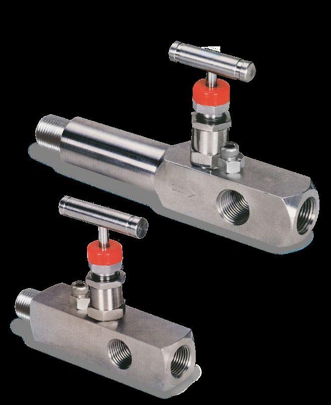
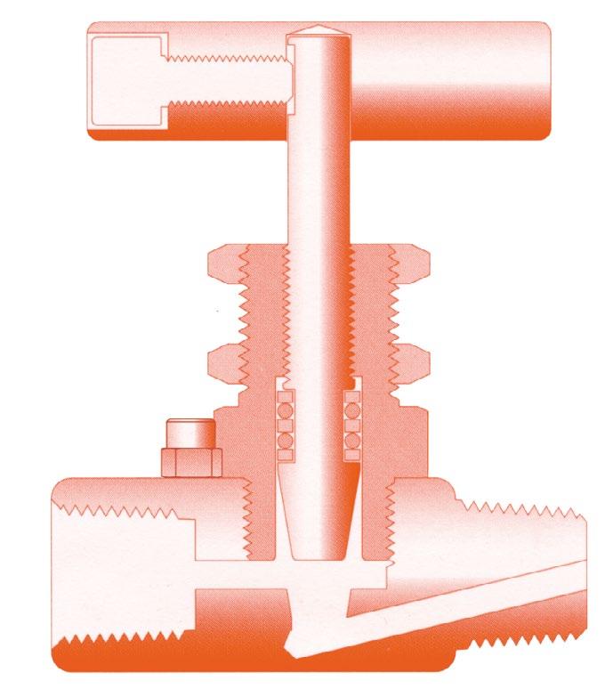
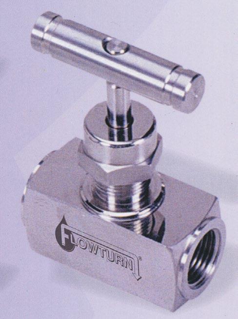
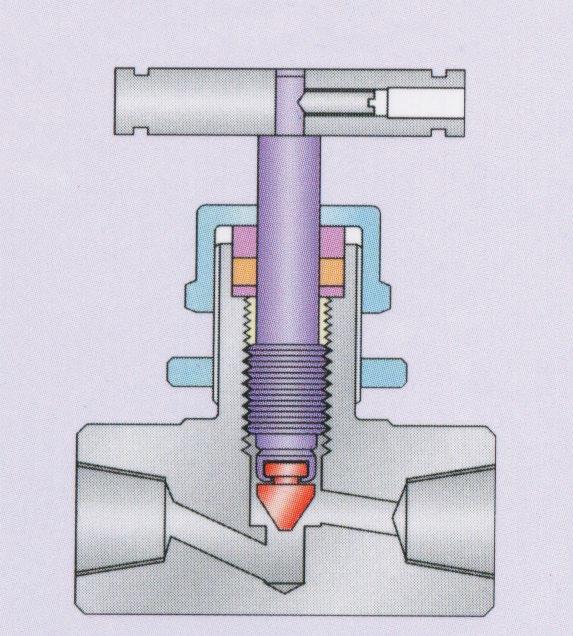
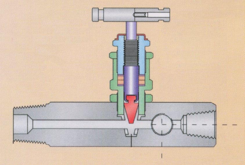
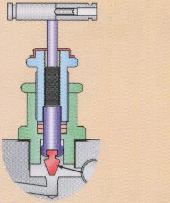
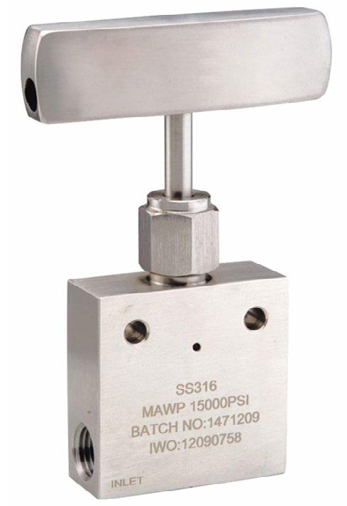
Flowturn ‘HB’ Series Globe Pattern Needle Valves are specially designed and ruggedly manufactured for use in corrosive and hazardous environment. ‘HB’ Series valves are used in process control, instrumentation and flow control applications. ‘HB’ Series are precision machined, and designed for durability and maximum efficiency to provide a high quality valve for use in fluid and gaseous control systems of different applications, to meet the exacting standards of our growing and demanding customers. The model S-M9 is complete with an integral bleed plug.
Flowturn ‘HB’ Series Valves are available in high grade stainless steel, carbon steel, monel and other materials in variety of end connections including male / female threaded NPT, BSP, BSPT, ISO, DIN and JIS tapered pipe ends. Valves can be supplied to meet current revision of NACE MR01-75 (Sour Gas Service). All valves are 100% factory tested and complete traceability is available upon request.
FEATURES - BENEFITS
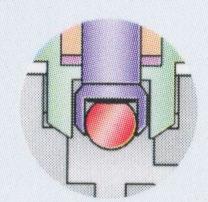
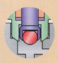
• Non rotating vee / ball tip design - which forms a bearing joint with the stem eliminates rotation between plug and seat at closure. This prevents scoring and galling up the valve seat and ensure long life in repetitive shut off service.
• Safety bonnet lock - prevents accidental disassembly.
• Stem thread rolled and hard plated - provides additional strength and maximum service life
• Mirror finish stem, burnished to Ra 0.20 µm (8~10 RMS) - extends packing life and smooth stem operation. Fugitive Emission compliant.
• Adjustable packing below stem threads - prevents stem lubrication washout and isolate threads from process contamination.
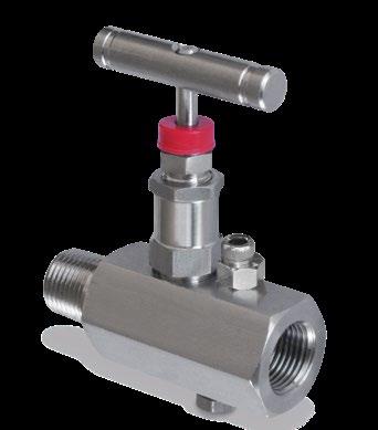
• Safety back seating - provides secondary stem seal in full open position, prevents stem blow out.
• Stainless steel handle - for proper actuation.
• Body to bonnet seal - metal to metal constant compression isolates bonnet threads from system fluids.
• Dust cap - prevents contaminants and lubricant washout of bonnet assembly.
• Repairable Metal Seat - can be resurfaced without removing valve from line.
MATERIAL OF CONSTRUCTION
or zinc plated See Page 15 for dimensions (same as S-H7-PM).
TESTING
Every Flowturn ‘HB’ Series Needle Valve is 100% tested with nitrogen gas at 1200 psig (80Bar) for leakage at seal and seat. Hydrostatic test performed with pure water at 1 1/2 times the working pressure. Other optional tests like helium and low temperature are available upon request. PRESSURE/TEMPERATURE RATINGS
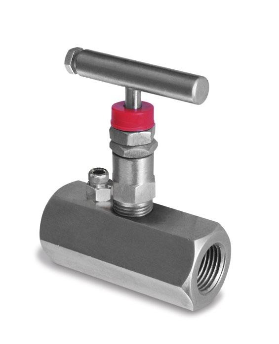
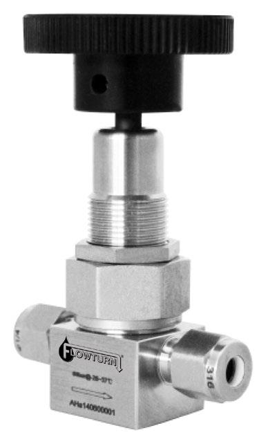
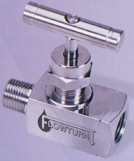
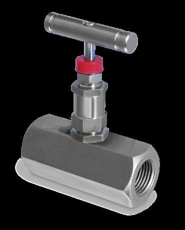
Flowturn ‘IB’ Series Panel Mount Globe Type Needle Valves are specially designed and ruggedly manufactured for use in corrosive and hazardous environments. ‘IB’ Series valves are used in Process control, instrumentation and flow control applications. ‘IB’ Series Valves are precision machined, and designed for durability and maximum efficiency to provide a high quality valve for use in fluid and gaseous control systems of different applications, to meet the exacting standards of our growing and demanding customers.
Flowturn ‘IB’ Series Valves are available in high grade stainless steel, carbon steel, monel and other materials in a variety of end connections including male / female threaded NPT, BSP, BSPT, ISO, DIN and JIS tapered pipe ends. Valves can be supplied to meet current revision of NACE MR01-75 (Sour Gas Service). All valves are 100% factory tested and complete traceability is available upon request. Model S-H71-PM 10,000 psi is also available.
FEATURES - BENEFITS
• One piece body construction no welding used - for high strength and safety.
• Non rotating vee / ball tip design - which forms a bearing joint with the stem eliminates rotation between plug and seat at closure. This prevents scoring and galling up the valve seat and ensure long life in repetitive shut off service.
• Stem thread rolled and hard plated - provides additional strength and maximum service life.
• Mirror finish stem, burnished to Ra 0.20 µm (8~10 RMS) - extends packing life and smooth stem operation. Fugitive Emission compliant.
• Stainless steel handle - for proper actuation.
• Repairable Metal Seat - can be resurfaced without removing valve from line.
MATERIAL OF CONSTRUCTION
PRESSURE/TEMPERATURE RATINGS
TESTING
Every Flowturn ‘IB’ Series Needle Valve is 100% tested with nitrogen gas at 1200psig (80Bar) for leakage at seal and seat. Hydrostatic test performed with pure water at 1 1/2 times the working pressure. Other optional tests like helium and low temperature are available upon request.
NEEDLE VALVE MODEL S-H7-PM
DIMENSIONS* (MM)
NEEDLE VALVE I.B. FF (MODEL S-H7-PM)
DIMENSIONS* (MM)
NEEDLE VALVE I.B. OD (MODEL S-H7-PM)
DIMENSIONS* (MM)
WARNING: Inadequate care and improper utilisation of valves can cause intense and excessive damage to life and property. Flowturn’s products are not for your liable use and at the behest of the user’s responsibility to check and analyse the service in which it is going to be inserted into, so that the valve functions properly and the relevant product type and materials have been selected. Also all other precautions should be taken before the user puts the product into service.
Flowturn SH1 and S-M9S Needle Valves are specially designed and ruggedly manufactured for use in corrosive and hazardous environment. S-H1 & S-M9S valves are used in process control, instrumentation and flow control applications. ‘HB’ Series are precision machined, and designed for durability and maximum efficiency to provide a high quality valve for use in fluid and gaseous control systems of different applications, to meet the exacting standards of our growing and demanding customers. The model S-M9S is complete with an integral bleed plug.
Flowturn Needle Valves are available in high grade stainless steel, carbon steel, monel and other materials in variety of end connections including male/female threaded NPT, BSP, BSPT, ISO, DIN and JIS tapered pipe ends. Valves can be supplied to meet current revision of NACE MR01-75 (Sour Gas Service). All valves are 100% factory tested and complete traceability is available upon request.
FEATURES - BENEFITS
• Straight through flow path - provides high flow capacity bi-directional ‘roddable’ capability.
• Safety bonnet lock - prevents accidental disassembly.
• Stem thread rolled and hard plated - provides additional strength and maximum service life.
• Mirror finish stem, burnished to Ra 0.20 µm (8~10 RMS) - extends packing life and smooth stem operation. Fugitive Emission compliant.
• Adjustable packing below stem threads - prevents stem lubrication washout and isolate threads from process contamination.
• Safety back seating - provides secondary stem seal in full open position, prevents stem blow out.
• Stainless steel handle - for proper actuation.
• Body to bonnet seal - metal to metal constant compression isolates bonnet threads from system fluids.
• Dust cap - prevents contaminants and lubricant washout of bonnet assembly.
MATERIAL OF CONSTRUCTION
Every Flowturn Needle Valve is 100% tested with nitrogen gas at 1200 psig (80Bar) for leakage at seal and seat. Hydrostatic test performed with
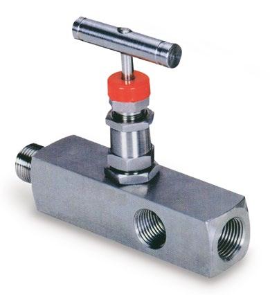
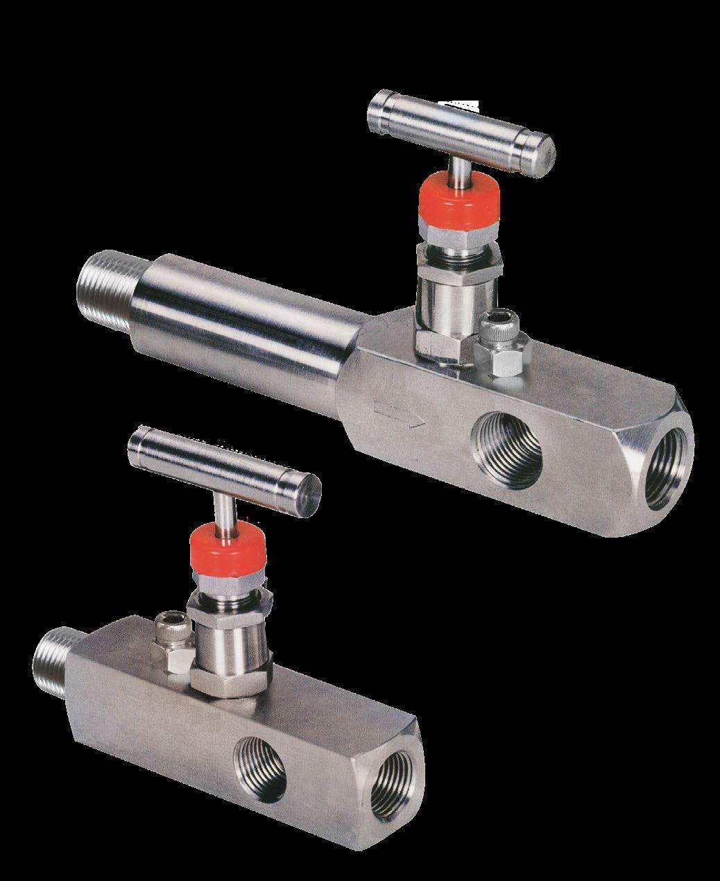
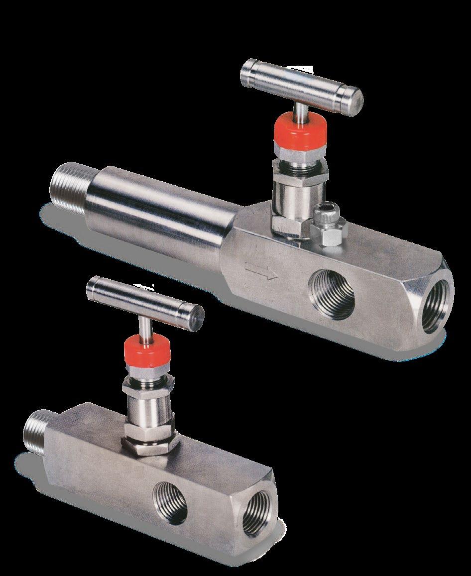
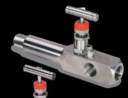
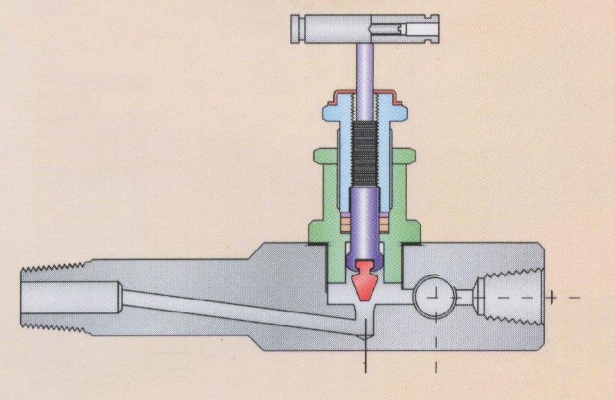
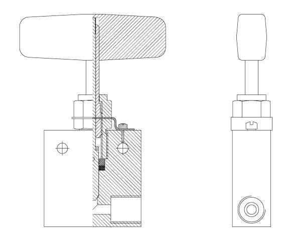
Flowturn Gauge Root Globe and Plug Type Needle Valves are used for safe installation in pressure switches, gauges and differential pressure transmitters, suitable for blockand bleed assemblies to test pressure source required in sampling line or purge valve.
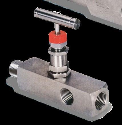
316 S.S. construction for corrosion resistance. Non rotating vee or ball tip. Extended body for insulation clearance. Scheduled 160 or heavier pipe valve inlet for strength. Optional graphoil packing available for high temperatures. Ball*/vee tip design forms a bearing joint with the stem which eliminates rotation between ball/vee tip and seat at closure. This prevents scoring and galling up the valve seat and ensures long life in repetitive shut off service.

• Non rotating vee / ball* tip design - which forms a bearing joint with the stem eliminates rotation between plug and seat at closure. This prevents scoring and galling up the valve seat and ensure long life in repetitive shut off service.
• Safety bonnet lock - prevents accidental disassembly.
• Stem thread rolled and hard plated - provides additional strength and maximum service life.
• Mirror finish stem, burnished to Ra 0.20 µm (8~10 RMS) - extends packing life and smooth stem operation. Fugitive Emission compliant.
• Adjustable packing below stem threads - prevents stem lubrication washout and isolate threads from process contamination.
• Safety back seating - provides secondary stem seal in full open position, prevents stem blow out.
• Stainless steel handle - for proper actuation.
• Body to bonnet seal - metal to metal constant compression isolates bonnet threads from system fluids.
• Dust cap - prevents contaminants and lubricant washout of bonnet assembly.
• Repairable Metal Seat - can be resurfaced without removing valve from line.
*Ball tip available as option only on S-M5 globe style.
Each valve is tested with nitrogen gas at 1000 psi for seat and packing leakage with a maximum allowable leak rate of 0.1 sec/min. Hydro test performed with pure water at 1
/2 times the working pressure. Other tests like vibration and temperature, helium etc. are available upon requests.
Flowturn Mini Series Needle Valves are specially designed and ruggedly manufactured for use in corrosive and hazardous environment. Mini valves are used in process control, instrumentation and flow control application. Mini valves are precision machined, and designed for durability and maximum efficiency to provide a high quality valve for use in fluid and gaseous control systems of different applications, to meet the exacting standards of our growing and demanding customers.
Flowturn Mini Series Valves are available in high grade stainless steel, carbon steel, monel and other materials in a variety of end connections including male / female threaded NPT, BSP, BSPT, ISO, DIN and JIS tapered pipe ends. Valves can be supplied to meet current revision of NACE MR-01-75 (Sour Gas Service).
FEATURES - BENEFITS
• One piece body construction no welding - for high strength and full safety.
• Vee tip design - controls accurate flow.
• Dust cap - prevents contaminants and lubricant washout of bonnet assembly.
• Stem thread rolled and hard plated - provides additional strength and maximum service life.
• Mirror finish stem, burnished to Ra 0.20 µm (8~10 RMS) - extends packing life and smooth stem operation. Fugitive Emission compliant.
• Stainless steel handle - for proper actuation.
MATERIAL OF CONSTRUCTION
5
6
DIMENSIONS (MM)
TESTING
in 1/4”, 3/8”, 1/2”
Every Flowturn Needle Valve is 100% tested with nitrogen gas at 1200psig (80Bar) for leakage at seal and seat. Hydrostatic test performed with pure water at 1 1/2 times the working pressure. Other optional tests like helium and low temperature are available upon request. PRESSURE/TEMPERATURE RATINGS
PEEK (3/16”) [4.8MM]
PEEK (1/4”) [6.4MM] Delrin® (3/16”) [4.8MM] PCTFE (KELF) (3/16”) [4.8MM] Delrin® (1/4”) [6.4MM] Teflon®
Denotes intersecting data * Based on up to 6.4mm orifice. Temperature also may be limited by PTFE
PRESSURE TEMPERATURE SEAT RATING* 10,000PSI * Based on up to 4.8mm orifice.
[°C]
PEEK
Delrin®
Denotes intersecting data
Flowturn ARY - S15K Needle Valves are specially designed and ruggedly manufactured for use in corrosive and hazardous environment. S15K valves are used in process control, instrumentation and flow control application. S15K valves are precision machined and designed for durability and maximum efficiency to provide a high quality valve for use in fluid and gaseous control systems of different applications, to meet the exacting standards of our growing and demanding customers. Valves can be supplied to meet current revision of NACE MR-01-75 (Sour Gas Service).
BENEFITS
One piece heavy duty body construction no welding - for high strength and full safety. Vee tip design - ensures accurate flow control.
Stem thread rolled and hard plated - provides additional strength and maximum service life. Mirror finish stem, burnished to 16RMS - extends packing life and smooth stem operation. Stainless steel handle - for proper actuation.
FEATURES
• NPT threads to assure 15,000 psi.
• Valve design provides in-line pipe connections for 1/4” to 1/2” pipe sizes.
• Rising stem & bar stock body design.
• Non-rotating stem prevents stem/seat galling. These stems are standard for on-off service and insure long life on valve seats.
• Metal-to-metal seating achieves bubble-tight shut-off, longer stem/seat life in abrasive flow, greater durability for repeated on/off cycles and excellent corrosion resistance.
• PTFE (Teflon) encapsulated packing provides dependable stem and body sealing. Teflon 232°C (450°F) standard with optional Viton 177°C (350°F), BUNA-N 93°C (200°F) and Grafoil 343°C (650°F) available.
• Materials include high tensile Type 316 stainless steel for valve bodies and hardened 17-4PH stainless steel for lower section stems. Stem sleeve and packing gland materials have been carefully chosen to achieve extended thread cycle life and reduced handle torque.
• Operating temperature range from -17°C (0°F) TO 204°C (400°F).
MATERIAL OF CONSTRUCTION
DIMENSIONS
TESTING
Every Flowturn Needle Valve is 100% tested with nitrogen gas for leakage at
Other optional tests like helium and low temperature are available upon request.
and seat. Hydrostatic test performed with
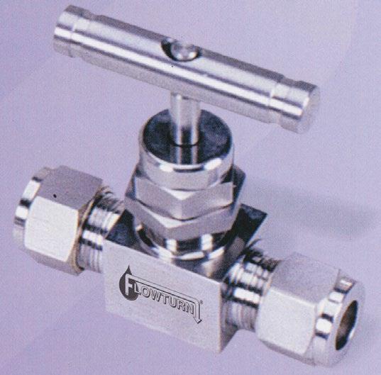
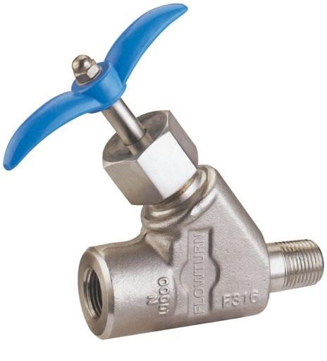
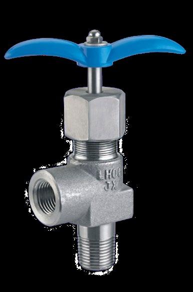
Flowturn KER-JY Series Needle Valves, with their rugged compact design, offer positive shut off or directional control of fluids in process, oilfield wellhead and instrumentation applications. The unique proven design ensures excellent sealing characteristics while accomodating a superior temperature range and cycle life. A high integrity metal to metal bonnet anti ingress seal ensures leak tightness at high pressures.
These valves are available in Y-type and right angle configurations in steel, stainless steel, Monel, Duplex and Inconel construction, with a wide variety of port connections.
• Globe Style, Metal Seat.
• Compact and lightweight.
• Pressure responsive PTFE packing seal arrangement.
• Bi-directional flow, with preferred flow indicated.
• Ingress seals fitted as standard.
• Full material traceability of main components.
• 100% Hydrotestic testing.
• Materials of construction can be supplied to NACE MR 01-75.
Flowturn ‘KER-JY’ Series Valves are available in high grade stainless steel, carbon steel, monel and other materials in variety of end connections including male / female threaded NPT, BSP, BSPT, ISO, DIN and JIS tapered pipe ends. Valves can be supplied to meet current revision of NACE MR01-75 (Sour Gas Service). All valves are 100% factory tested and complete traceability is available upon request.
FEATURES - BENEFITS
• Non rotating vee / ball tip design - which forms a bearing joint with the stem eliminates rotation between plug and seat at closure. This prevents coring and galling up the valve seat and ensure long life in repetitive shut off service.
• Safety bonnet lock - prevents accidental disassembly.
• Stem thread rolled and hard plated - provides additional strength and maximum service life.
• Mirror finish stem, burnished to Ra 0.20 µm (8~10 RMS) - extends packing life and smooth stem operation. Fugitive Emission compliant.
• Adjustable packing below stem threads - prevents stem lubrication washout and isolate threads from process contamination.
• Safety back seating - provides secondary stem seal in full open position, prevents stem blow out.
• Body to bonnet seal - metal to metal constant compression isolates bonnet threads from system fluids.
• Repairable Metal Seat - can be resurfaced without removing valve from line.
MATERIAL OF CONSTRUCTION
1
2 Gland Body 1 A479-316 / A-105*
3 Gland Retainer 1 A479-316 / A-105*
4 Washer 1 A479-316
5 Packing 1 PTFE / Graphoil
6 Packing
7
8
9
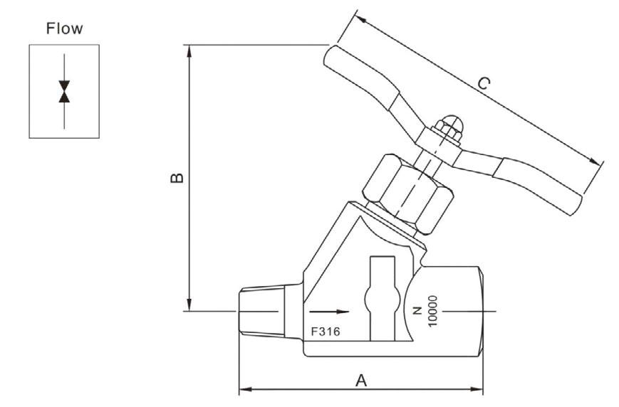
SPECIFICATIONS
Pressure Rating Up to 10,000PSI (700 Bar)
Size Range 1/4” to 1”
Temperature Rating PTFE Packing
-54°Cto 200°C (-65°F to 392°F)
Graphite Packing
-50°C to 550°C (-58°F to 1022°F)
Tube compression - Twin Ferrule
Port Connections
NPT (Male / Female)
BSP
DIMENSIONS
TESTING
Every Flowturn ‘KER-JY’ Series Needle Valve is 100% tested with nitrogen gas at 1200 psig (80Bar) for leakage at seal and seat. Hydrostatic test performed with pure water at 1 1/2 times the working pressure. Other optional tests like helium and low temperature are available upon request.
The SLNT6000 is an economical Globe Style Needle Valve with needle point tip. This valve has a smaller orifice than the S-H7 Globe Type Needle Valve. This valve is available in Female X Female and Male X Female end connections.
PRESSURE/TEMPERATURE CHART
SEATED VALVE)
graphite packing, metal seated version will do 315oC Max)
MATERIAL OF CONSTRUCTION
DIMENSIONS (MM)
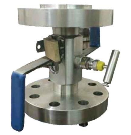
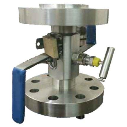
MONO FLANGE
Flowturn Design Mono Flange, Single block and bleed and Double block and bleed valves incorporate primary process valves together with standard isolation and vent needle valves in one single compact unit to offer a space, weight and cost saving compared to traditional block & bleed valve. The compact size allows the use of more expensive materials like 316 & F51 to provide a longer life.
FEATURES
• Single piece body with Bonnet assembly.
• Flange connection 15NB to 50NB (1/2” to 2”).
• TFE or Graphite Packing for Bubble tight sealing.
• Non-Rotating Tip to provide positive, bubble - tight seal.
• Metal to Metal Body/Bonnet Seal.
• Tbar Handle.
• Designed to comply with requirements of ANSI/ASME B16.5. Optional valve Bonnet assembly OS & Y bolted, Anti Tamper and globe Style assembly with non roating needle trim.
1500-lb, One -piece integrally forged valve -
• Reduced weight
• Reduced height
• Reduced leakage points
• Reduced effect of system vibration
• Supporting brackets are not required
• Reduced bending moment acting on the vessel branch fitting weld.
• Reduced installation cost
• Reduced gaskets and bolting
TECHNICAL
• NACE MR-01-75.
• ASTM (Gr) Stainless steel, F316/F316LCarbon steel, A150/ LF2 and duplex or Super duplex and Alloy (400, 625, 825 and C276).
• Heat Code for material traceable to EN 10204.3.1.B.
• End connection accordance with ASME B16.5 RF and RTJ NPTconnection accordance with ASME B1.20.1
• Working pressure in accordance to ASME B16.5 class 150 to 2500 class working temperature -58 to 400°F (-50 to 204°C ) for stainless steel and duplex -50 to 400°F (-46 to 204°C ) carbon steel valve
• All valves are 100% factory testing hydrostatically and pneumatic leakage accordance with BS 12266.1
Mono Flange Wafer Type
Double Block & Bleed Valve
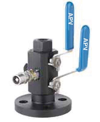
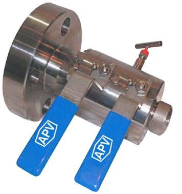
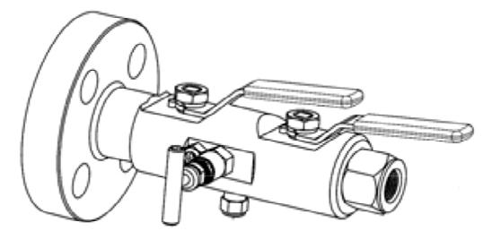
BALL/NEEDLE BALL ASSEMBLY
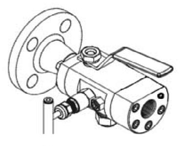
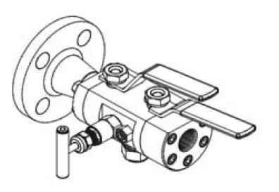
Flowturn provides needle/ball valve assembly in Single block and bleed and Double block and bleed in one single compact unit. This combination of primary and secondary valve provides shut off assurance & verification as well as space, weight and cost savings. This style is configured with one ball and one needle isolation valve in-line with an additional needle valve side bleed for block & bleed use. Flowturn can supply this style of valve in very short delivery in A105N, LF2, 316, F51, etc., in 150 to 2500 class
FEATURES
• Process interface in one compact ball/needle ball valve assembly.
• Three piece bolted body and integral single piece forged body styles.
• Flanged or Flanged & Screwed connection 15NB to 100NB (1/2” to 4”).
• Graphite packing for bubble tight sealing.
• Ball seats in PTFE, Delrin or PEEK.
• Bore size available 10mm to 100mm.
• Anti-blowout valve stems and non rotating needles.
• Fire safe designed to meet API 607.
• Optional vent valve bonnet assembly, OS&Y bolted, Anti-Tamper and globe style assembly with non-rotating needle trim.
• NACE MR-01-75.
• ASTM (Gr) Stainless steel, F316/F316L carbon steel, A105/ LF2 and duplex F51/F53 and Alloy 400, 625, 825 and C276.
• Heat Code for material traceable to EN 10204.3.1.B.
• Flange connection accordance with ASME B16.5 RF, RTJ or NPT connections in accordance with ASME B1.20.1.
• Working pressure in accordance to ASME B16.5 class 150 to 2500 class working temperature -58 to 400°F (-50 to 204°C) for stainless steel and duplex -50 to 400°F (-46 to 204°C) for carbon steel valve.
• All valve 100% factory testing hydrostatically and pneumatic leakage accordance with BS 12266.1.

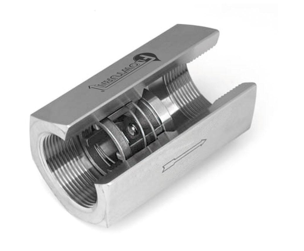
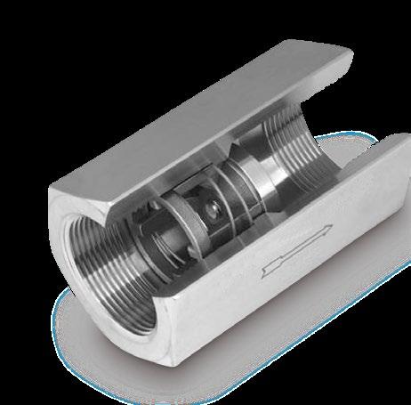
The CAV-3 check valve is a one piece body machined from bar stock and is designed for minimum pressure drop. The valve has a light weight compact design that provides maintenance-free dependable service. 10,000PSI Model also available to 2”
Note: All flow curves and Cv values presume the valves are fully open with 1/2 PSI cracking pressure springs. Consult the factory for more information.
ALLOY 20 = A2
BRASS = BR
CARBON STEEL = CS
HASTELLOY ®B = HB
HASTELLOY ®C = HC
MONEL® = MO
316 SS = SS
TITANIUM = TI
VALVE STYLE
SIZE
3/8 = C
1/2 = D
3/4 = F
1 = H
1-1/4 = I
1-1/2 = J
2 = K
2-1/2 = L
3 = M
4 = N
SPRING CRACKING PRESSURES
Replace “X” with actual desired setting. Must use decimal as a character. (PSI) FORMAT
0.000 TO 0.999 = .XXX
1.00 TO 9.99 = X.XX
10.0 TO
= XX.X
SPRING = NOSPRG STANDARD CRACKING PRESSURES (1)
.500 1.50 3.50 (Sizes C-I Only)
Note: Many other cracking pressures are available. Consult factory.
SPECIAL OPTIONS
T = FEP ENCAPSULATED SPRING Contact the factory for more options
SEAT MATERIAL (2)
AFLAS® = AS
BUNA-N = BN
EPDM = EP
KALREZ® = KZ
METAL-TO-METAL = MT
NEOPRENE = NE
PTFE = TF
VITON® = VT
SPRING MATERIAL
316 SS = SS
HASTELLOY®C = HC
HASTELLOY®B = HB
INCONEL® X-750 = IX
MONEL® = MO
17-7PH SS = PH
TITANIUM = TI
Listed above are the most common material selections. Please contact the factory for additional options.
(1) .500 PSI is the only standard cracking pressure for spring materials other than Stainless Steel.
Cracking pressure tolerance is +/- 15%. .125 PSI springs are not recommended for installations with flow vertical down.
(2) Seat materials other than metal-to-metal have a maximum pressure rating of 1500 PSI. PTFE seats are not resilient.
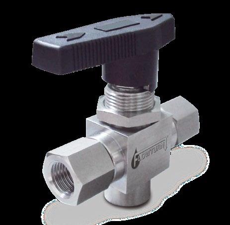
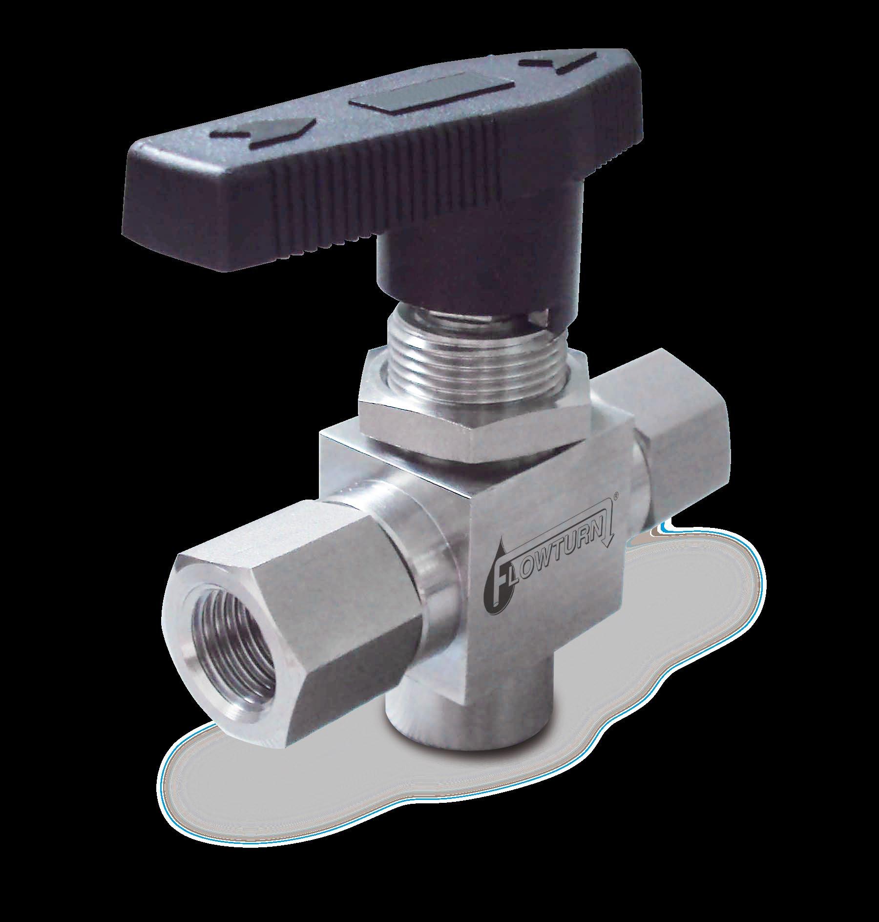
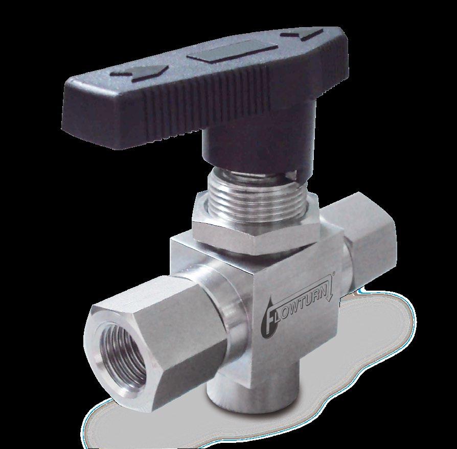
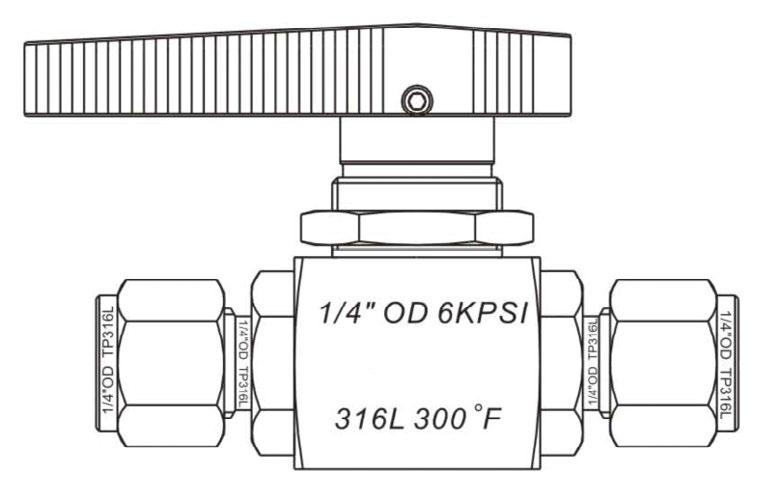
Flowturn 40 Series 3 way L-port Ball Valves, are a rugged compact design, offer positive shut off or directional control of fluids in process, power and instrumentation applications. The unique design ensures excellent sealing characteristics while accomodating a superior temperature range and cycle life.
A high integrity metal to metal bonnet anti ingress seal ensures leak tightness at high pressures up to 413 Bar (6000 PSI). These valves are available in two-way and multi-way 3/4/5 configurations in brass, 316 stainless steel, Monel and Inconel construction, with a wide variety of port connections. A trunnion mounted version with Kel-F or Polyaman or metal seats is available for higher pressures up to 689 Bar (10,000 PSI).
FEATURES
• 6~25 NB (1/4”~1”)
• Uni-Body, multi gland seal design*.
• L-port.
• Broad temperature range.
• Blow out proof stem.
• Available in one piece stem/ball*, floating ball.
• Panel mountable option.
• Bi-Directional flow.
• Handle indicates preferred direction of flow.
• Positive handle stops.
• 100% factory Nitrogen tested.
• Low operating torque.
• Vent option.
• Manual, electric or pneumatic actuation.
• Screwed tube fitting ends.
• Option - also available with 316SS handle and locking device
* Refer to drawing, several design options available.
MATERIAL OF CONSTRUCTION
• Ingress seals fitted as standard
• Flexible packing for replacement can extend field life further.
• Full material traceability of main components.
• Materials of construction can be supplied to meet the requirements of NACE MR-01-75 latest revision.
8
9
11
12
Also refer to pressure temperature ratings of elastomers (such as Viton and Buna) and the overall pressure rating of the valve design itself, can reduce the pressure temperature rating of the valve.
Configurations
way, 3-way, 4 way and 5 way
(1/4”~1”)
- Twin Ferrule
(Male / Female)
MODEL FCV3 (ONE WAY)
3000 SERIES
Available Size 1/8” to 1/2” pipe thread.
Pressure Rating Up to 16 bar [232psi]
Temperature Rating Up to 120OC
End Connection
BSP/BSPT/NPT/SAE Straight Thread
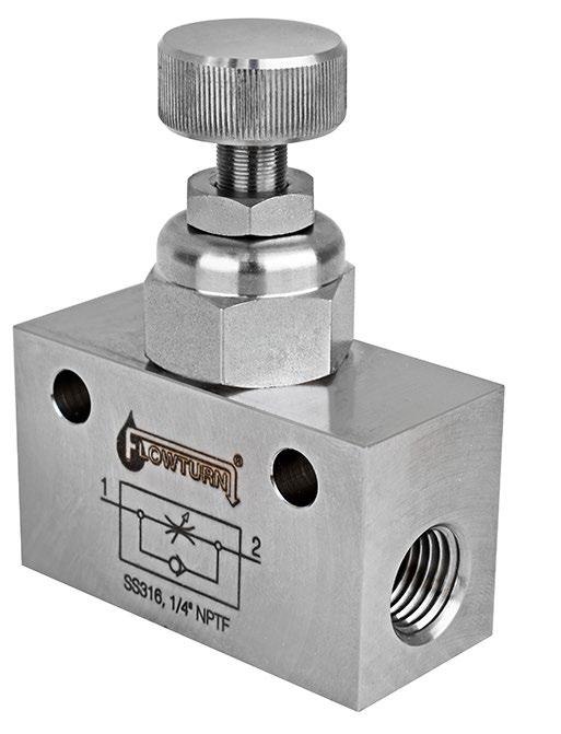
• Bifold style
• Side fixing panel or mount option.
MATERIAL OF CONSTRUCTION
MODEL FCV4 (BI-DIRECTIONAL)
4000 SERIES
Available Size 1/8” to 1/2” pipe thread.
Pressure Rating Up to 40 bar [580psi]
Temperature Rating Up to 120OC
End Connection
BSP/BSPT/NPT/SAE Straight Thread
8 Valve Body
(1) Adjustable Nut set to maximum travel. (3) Variable controllable open position.
DIMENSIONS
Allows direct exhaust of compressed air due to increase of cylinder rod displacement speed, this result in reductions of cycle time.
Operating Media Air, Sweet and Sour Gas
Available Size 8~25NB (1/4” to 1”) Pipe Thread
Pressure Rating Up to 12 bar [174psi]
Temperature Rating -20OC to 180OC Standard Service
Sealing Material Viton
End Connection
BSPP/BSPT/NPT Pipe Threads
Style Bifold Quick Acting Shuttle Style
OF CONSTRUCTION
PART NUMBER SYSTEM
S Standard Service (-20OC to 180OC) AS Arctic Service (-60OC to 60OC)
06 1/4” NPT
09 3/8” NPT
12 1/2” NPT
19 3/4” NPT 25 1” NPT FL-QEV Quick Exhaust Valve
NPT
Bug Vent
BSPP Straight Port Option
BSPT Taper Thread Option S - 06 - FL-QEV
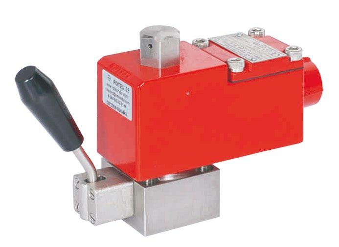
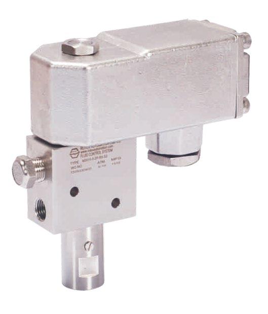
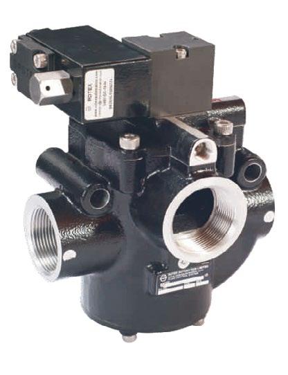
ATEX/ANZ/IEC EXd Hazardous, Flameproof, SIL Approved for Oil and Gas, Fertilizer, Power-Thermal, Metal, Chemical & Pharma etc..
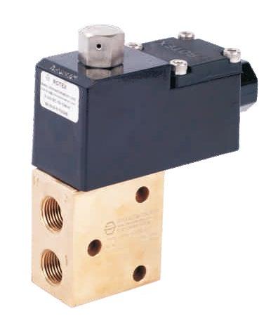
2/3/5 Way Solenoid valves with manual reset option, T3,T4,T6
IP 66, IP67 Positioners
complete electro-hydraulic actuation systems (linear multi/part turn and rotary in controls and on-off ) positioners
FLUID CONTROLS
3 Port Solenoid Valve

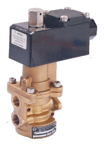
FLUID CONTROLS Positioners POWER-THERMAL
“Australian Pipeline Valve produces isolation, control and flow reversal protection products for severe and critical service media in utility, steam, pipelines, oil & gas and process industries. APV valves and pipeline products form the most competitive portfolio in the market.”