

Bonnet gasket:
Blank Standard:- SS + GRP (BB), Pressure Seal Ring (PSB). N/A:- (WB). A SS + PTFE B S318 03 Spiral C PTFE D SS + PTFE + GRP E Ring Z Special
Stem packing: Blank Standard:- Graphite. N/A:- (Check Valves) F Fugitive Emission GRP I Fugitive Emission PTFE J Special L Live Loaded P Graphite + PTFE T PTFE
Denotes special suffix - Packing/Gasket
Operator: Blank Handwheel or N/A A Actuator C Counter-Weight D Dampner G Gear H Hammer Blow Handwheel L External Lever
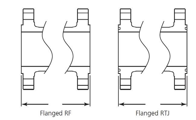
End connection: Blank RF (B16.5) BA RF B16.47A (MSS SP44)
BB RF B16.47B (API 605) RJ RTJ BW Buttweld FF Flat Face SP is special drilling UD Undrilled UM Unmachined for RF/RJ
Bonnet: Blank Bolted C Cryogenic H Pillar & Bridge L Low Temperature Ext. P Pressure Seal S Bellows Sealed T Threaded W Welded
Body material: - see page 5. (WCB is Blank)
Denotes special suffix - Body/Bonnet/Ends/Operator
Blank Non NACE N NACE C Cryogenic
Blank Standard Configuration (Example Solid Wedge) A S Bend Globe D Globe-Stop Check
DG Globe - Stop Check Guided F Flexible Disc Gate J Slab Gate K Expanding Gate L Lever (Swing Check)
P Full Opening Swing Check (API 6D) Q Full Opening Piston Check (API 6D) R Right Angle S Parallel Slide Y Inclined Bonnet Z c/w Spring
Denotes trim - Code & Modifier (see below)
Basic identifier number denoting valve class and valve type (As shown in catalogue)
Prefix: Blank APV FZV APV-FZV J.V.
Valve Size
BODY MATERIAL CODE • BODY/BONNET MATERIALS
(F55)
(F53) 22 A296 M-35 Monel 23 A296 CW-12M Hastelloy C
CUC
A494 CW6MC Inconel 625
B367 GR.C2 Titanium (F2) 28 B367 GR.C3 Titanium (F3) 29 A358 LC4 Low Temp. 4-1/2% Nickel Steel 30 A358 LC9 9% Nickel Steel 31 A358 CA6NM 18-1/2% Chromium, Nickel-Molybdenum Steel
32 A217 WC4
33 A217 WC5
34 A217 WC11
35 A217 C12
36 A217 C12A
37 A217 CA15
0 SPECIAL
Nickel Chromium Molybdenum
Nickel Chromium Molybdenum
Chromium Molybdenum
Chromium Molybdenum
Chromium Molybdenum Vanadium
Chromium Steel


ANSI CLASS 150 ~ 2500
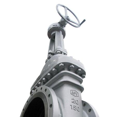
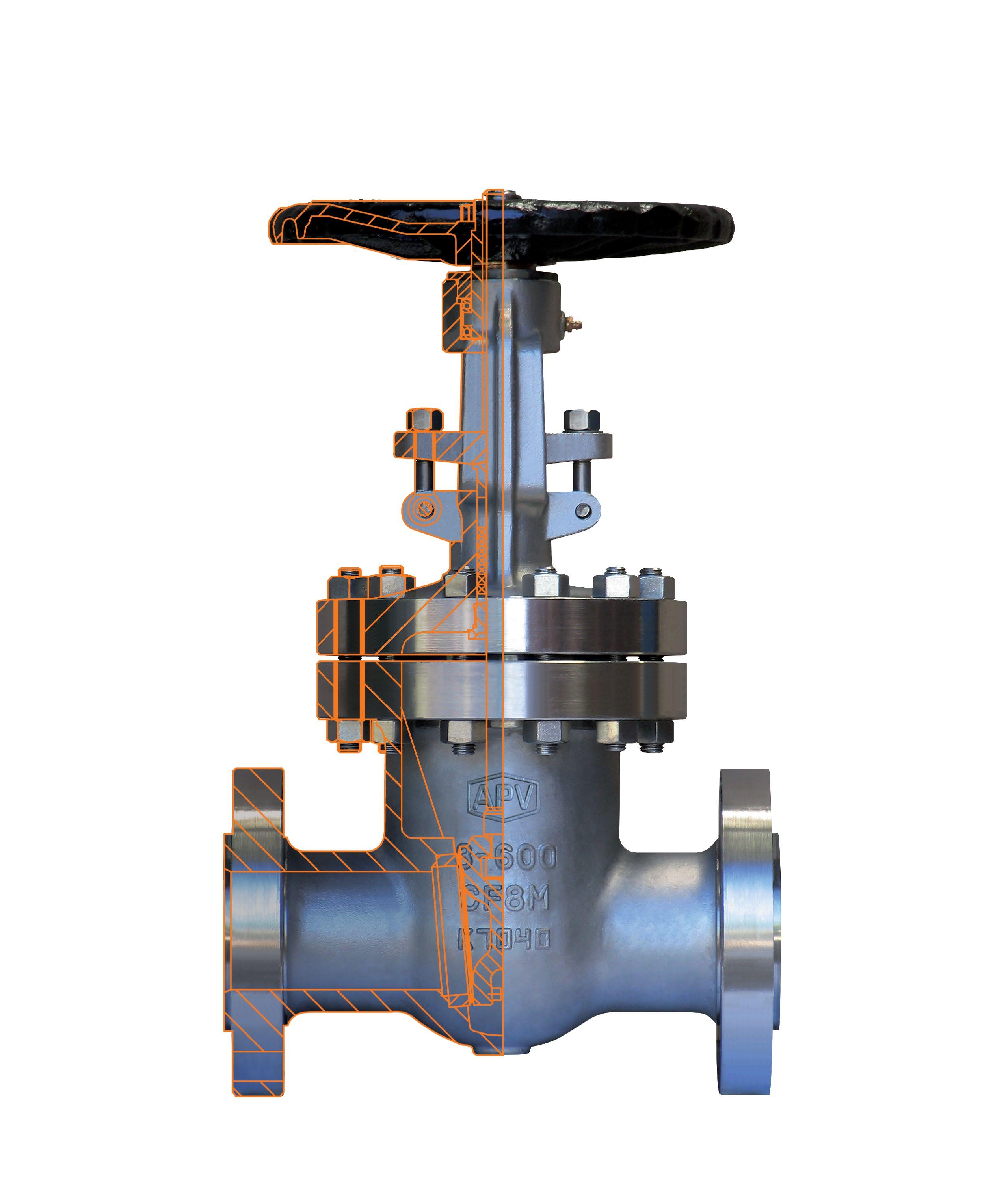
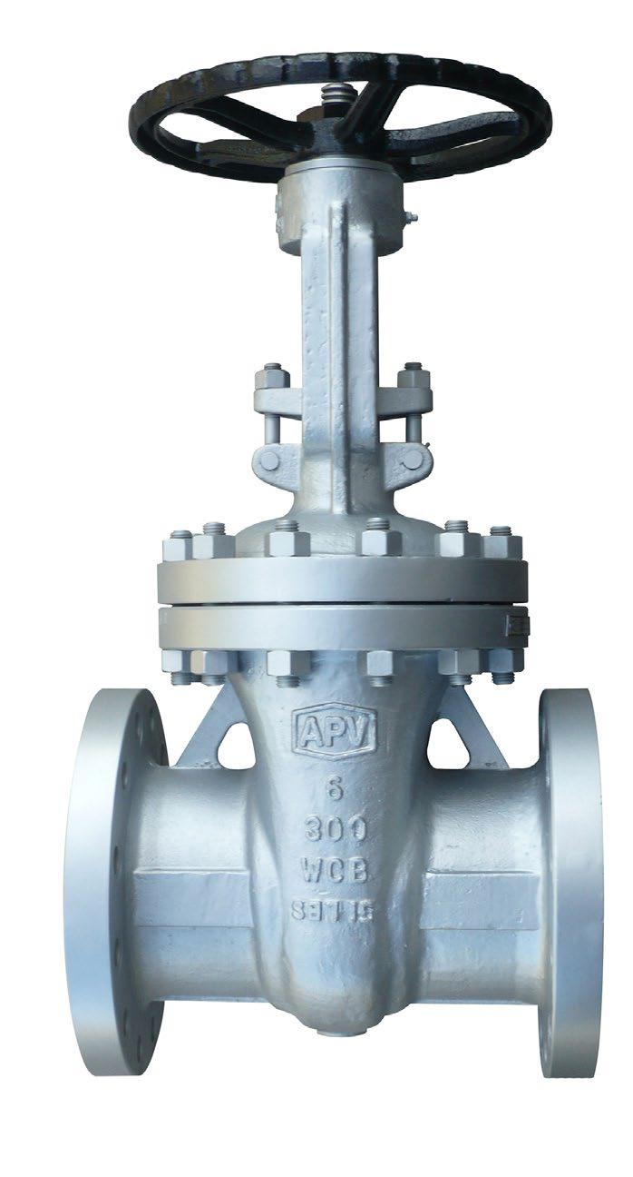
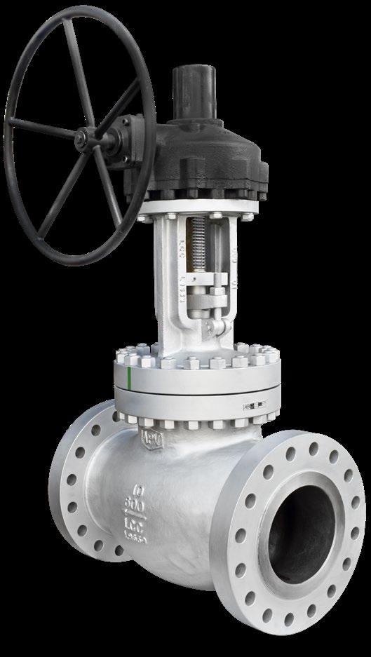
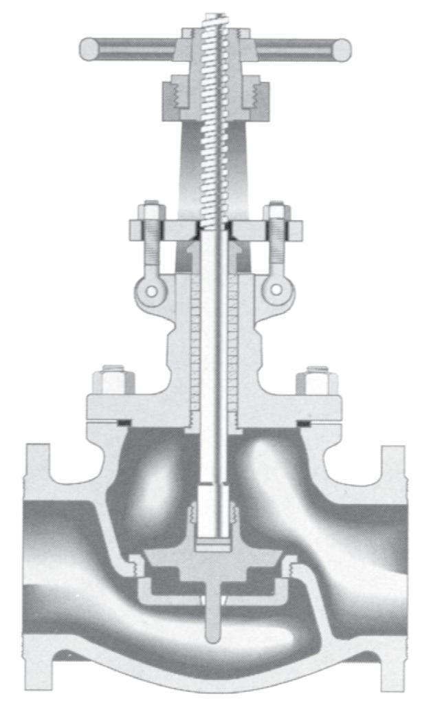
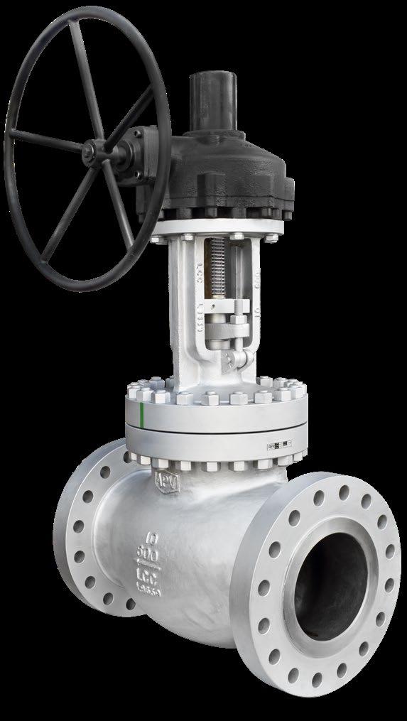
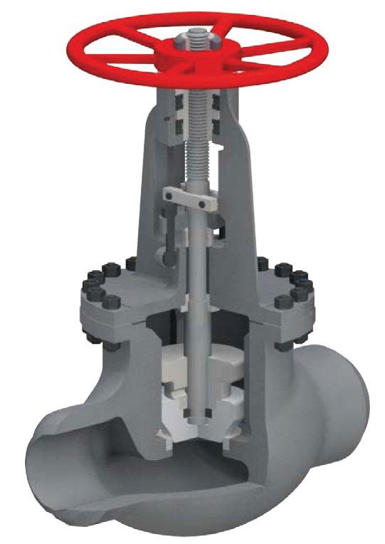
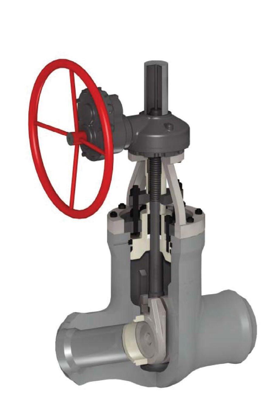
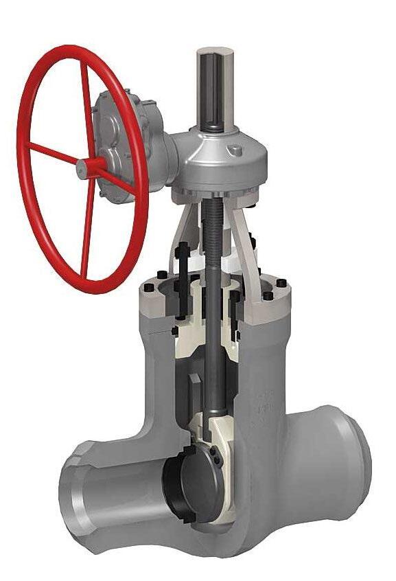
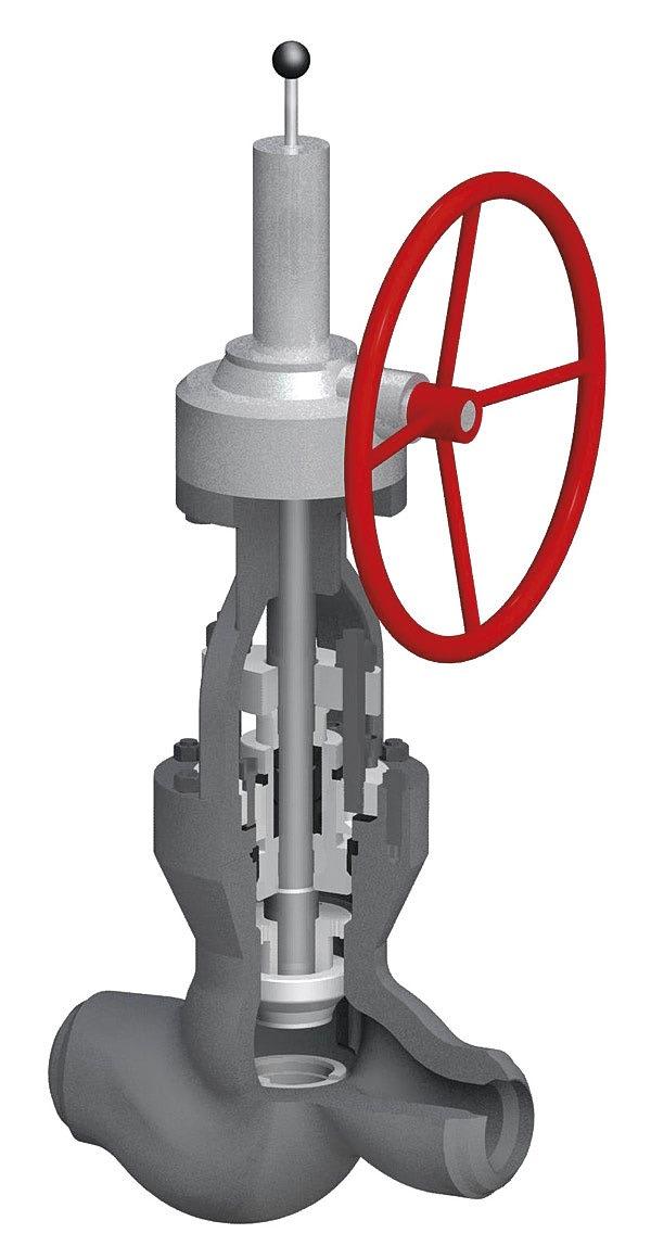
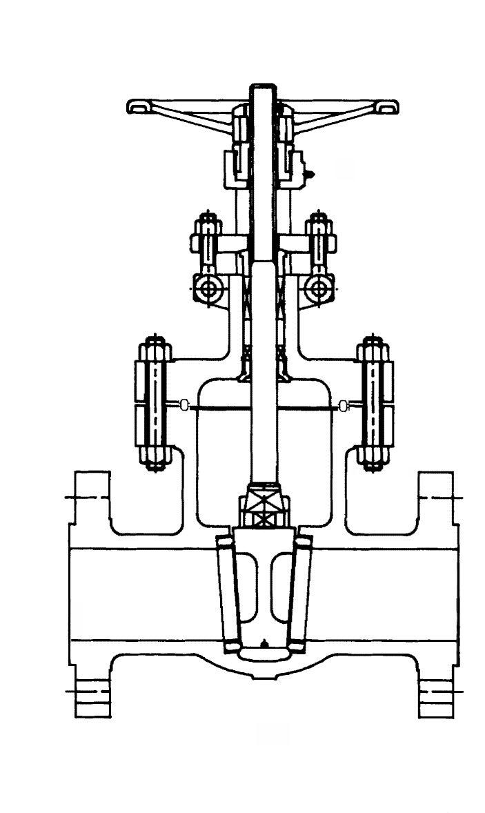
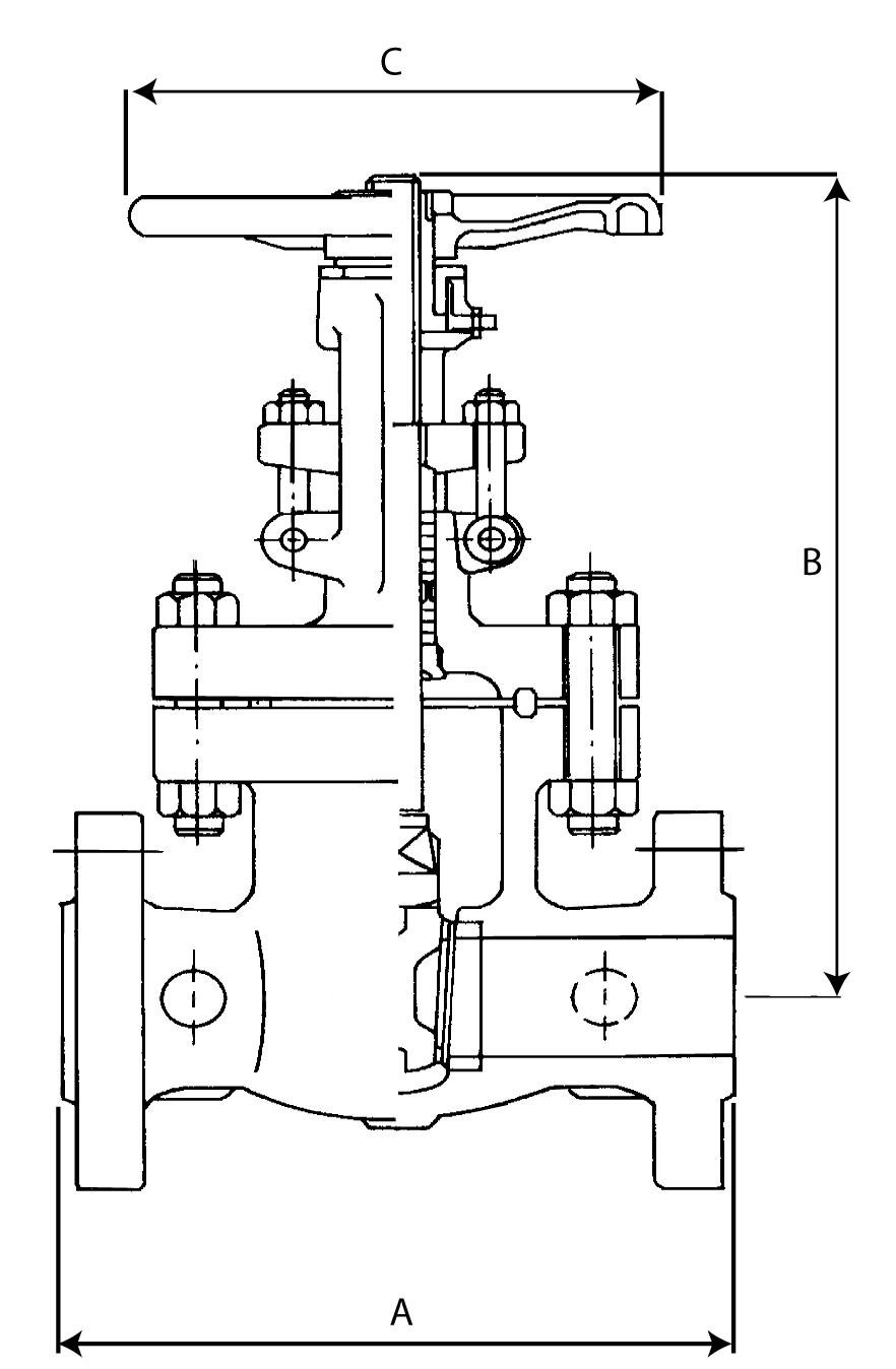
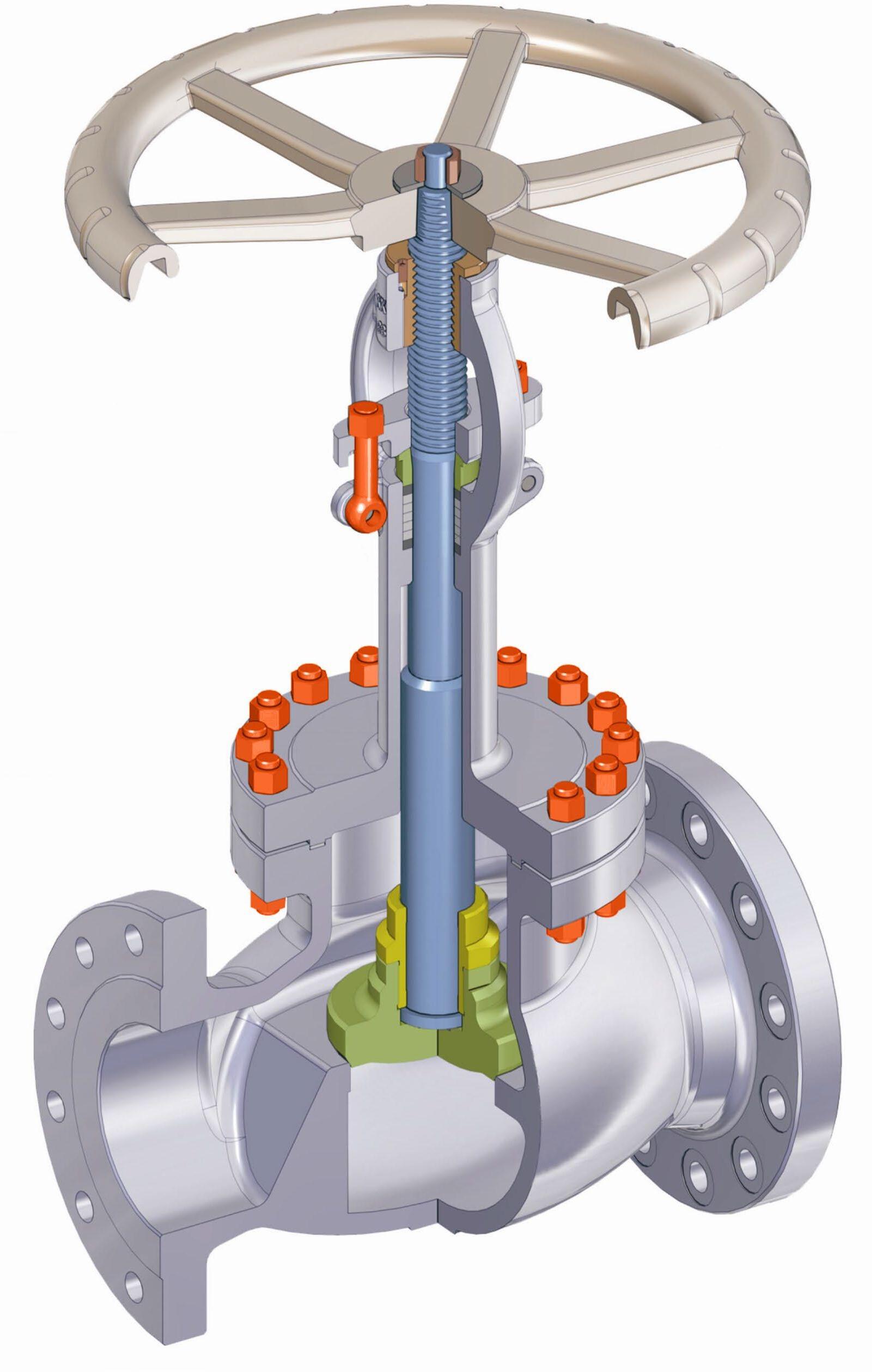
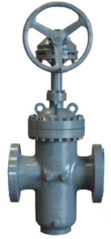
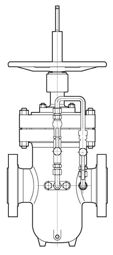
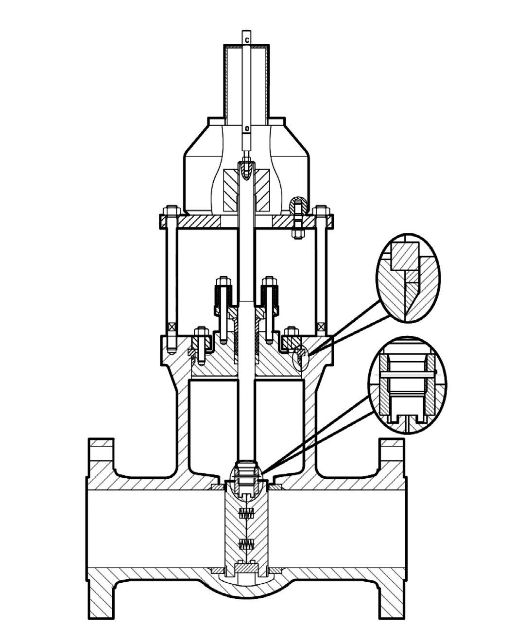
• Bolted bonnet, OS&Y, Flexible wedge.
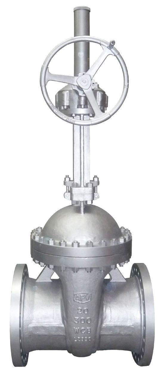
• On smaller size valves, the yoke is cast integral with bonnet. Larger size valves have two piece yoke, refer to individual drawing.
• Stem nut is mounted with ball bearings to reduce operating torque for ease of manual operation in larger sizes and higher classes.
• Self aligning two piece gland.
• Valves designed to API Std. 600
• Valves tested to API Std. 598
• Face-to-face to ANSI B16.10
• Flanged ends to ANSI B16.5
• Butt-welding ends to ANSI B16.25
• Trim and seating surface as per API 600 standard.
• Stuffing box smoothness ≤Ra 3.2 µm (superior • Stem smoothness to API 600 ≤Ra 0.80 µm MATERIAL LIST
4
5
1
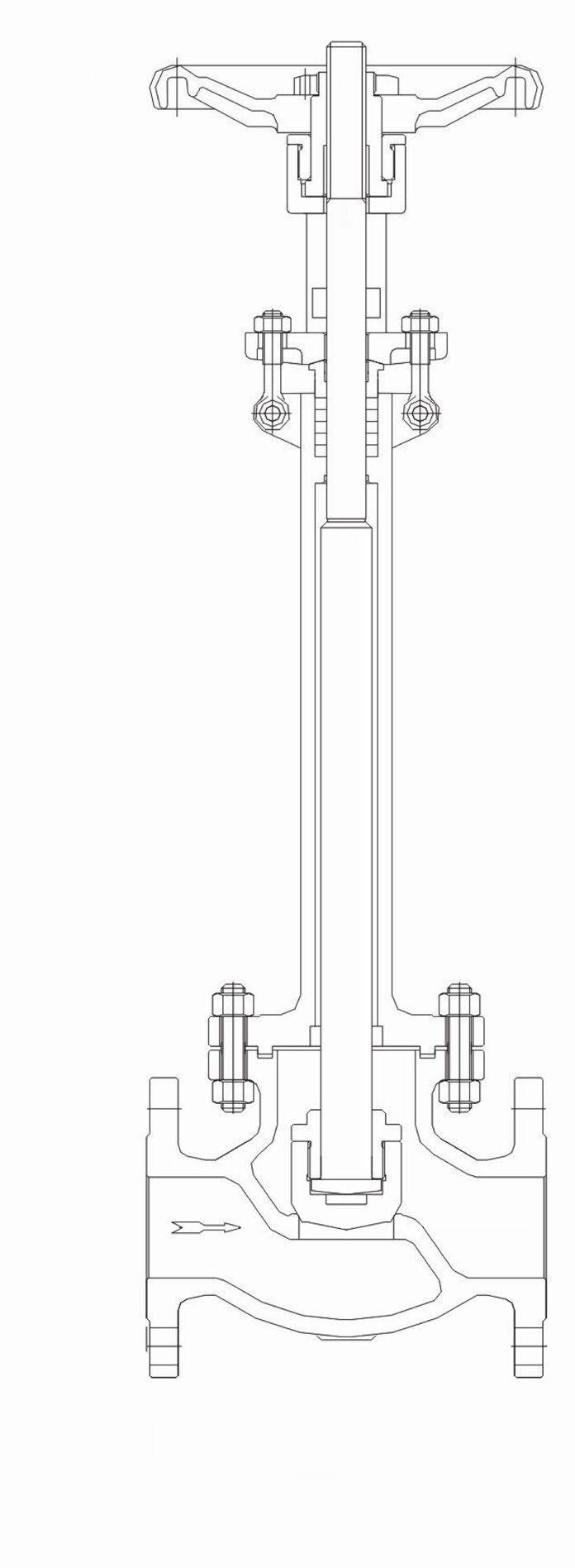
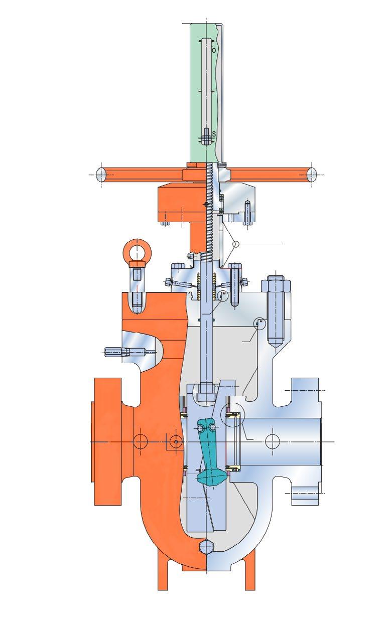
ANSI CLASS 150 ~ 2500
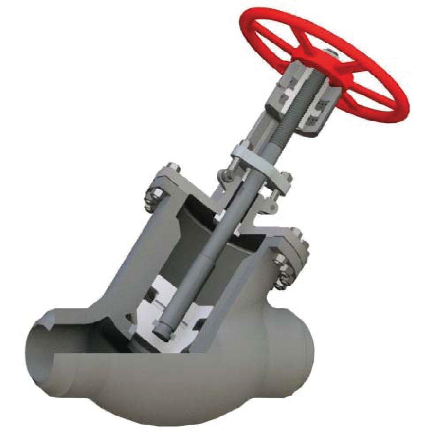
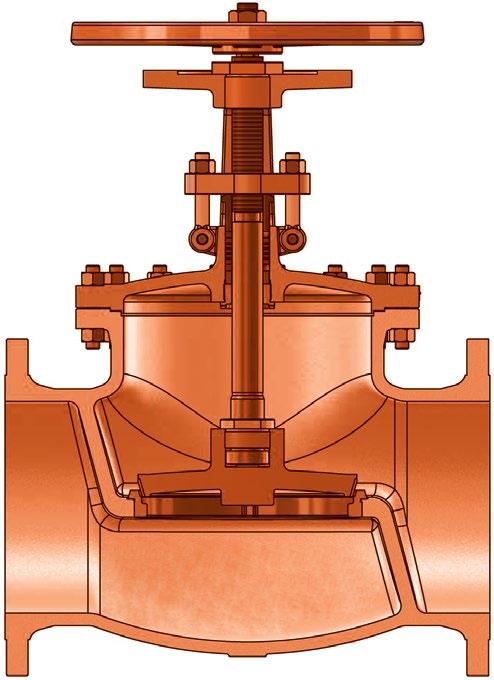
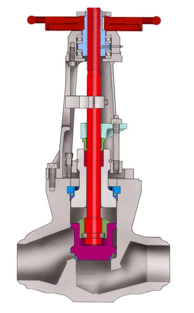
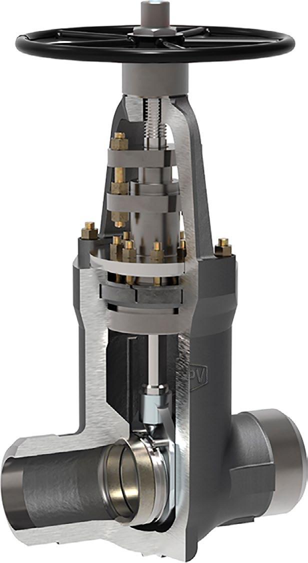
• Bolted bonnet, OS&Y, Swivel Disc.
• Plug type disc (Ball type also available).
• On smaller sizes, the yoke is cast integral with bonnet. Larger sizes have two piece yoke, refer to individual drawing.
• Stem nut is mounted with ball bearings to reduce operating torque for ease of manual operation in larger sizes and higher classes.
• Valves designed to ASME B16.34 / API 623
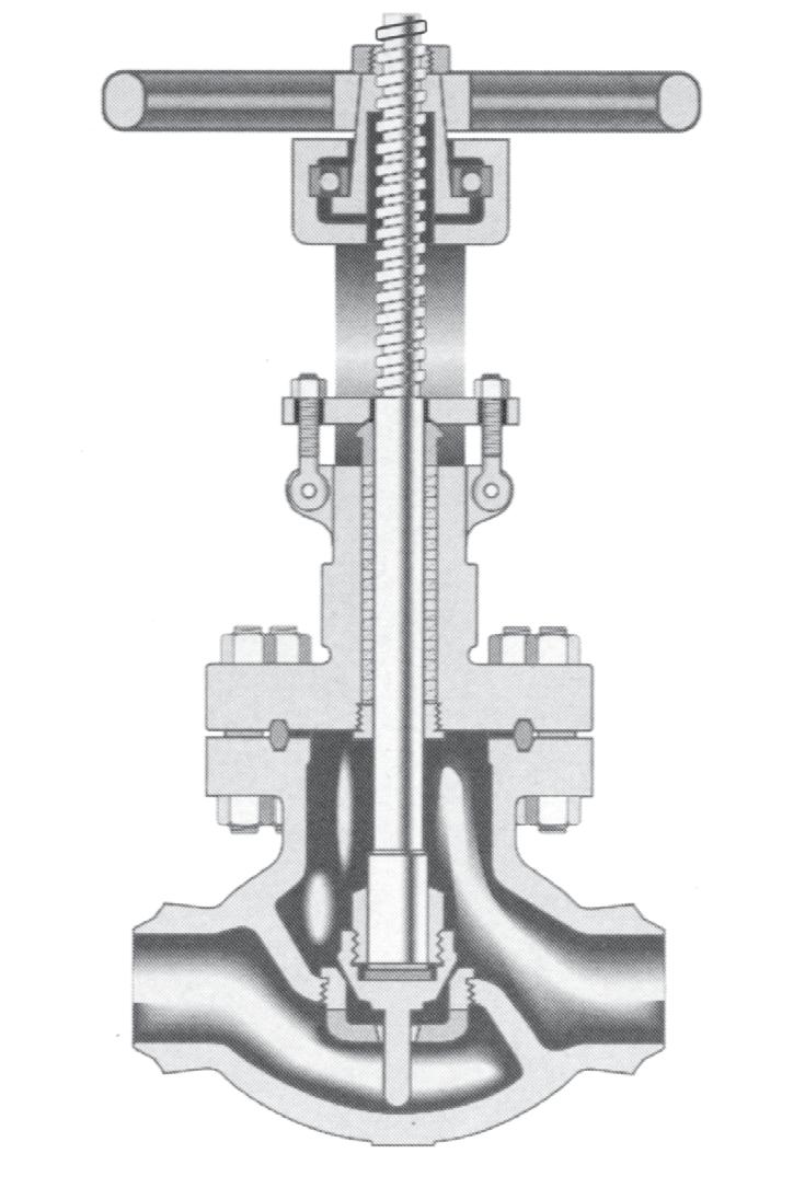
Body Guided Disc style eliminates side thrust and provides longer disc, seat and body life as well as ensuring positve shut-off and low closing torque.
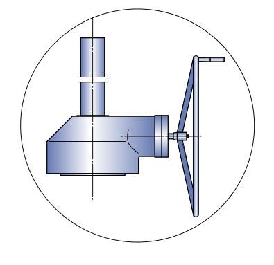
Torque Arm
wall thickness to API 623
• Valves tested to API Std. 598
• Face-to-face to ANSI B16.10
• Flanged ends to ANSI B16.5
• Butt-welding ends to ANSI B16.25
• Trim and seating surface as per API 600
• Stuffing box smoothness ≤Ra 3.2 µm (superior to API 623 / API 600)
• Stem smoothness to API 623 ≤Ra 0.80 µm
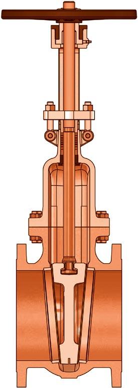
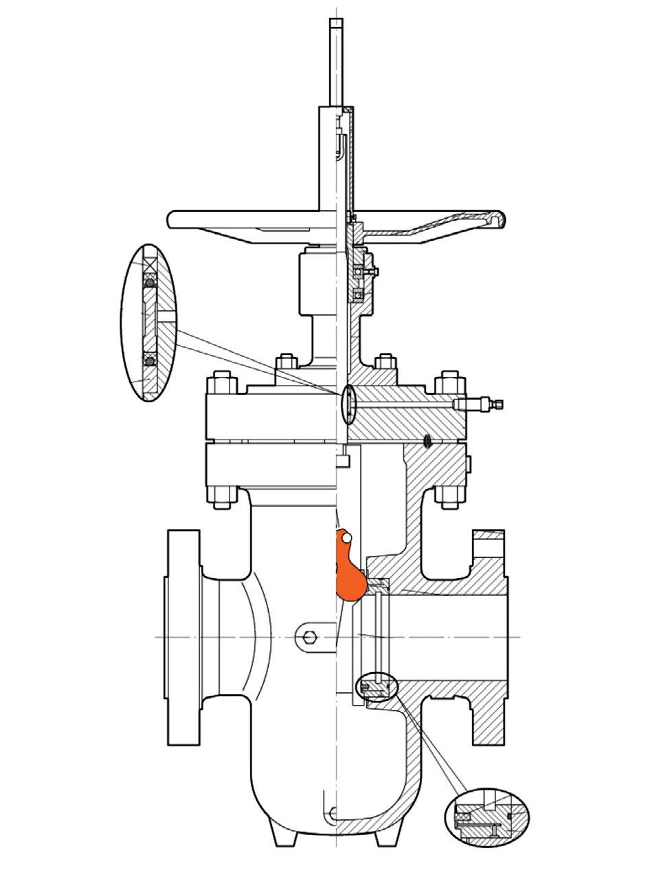
Used in larger sizes the torque arm prevents stem movement which reduces wear on packing rings and enables better sealing as well as reducing torque. Non rotating stem, only the stem nut rotates. The arm also provides visual stem position indication and can be interfaced with position switches. Optional live loaded packing system is shown.


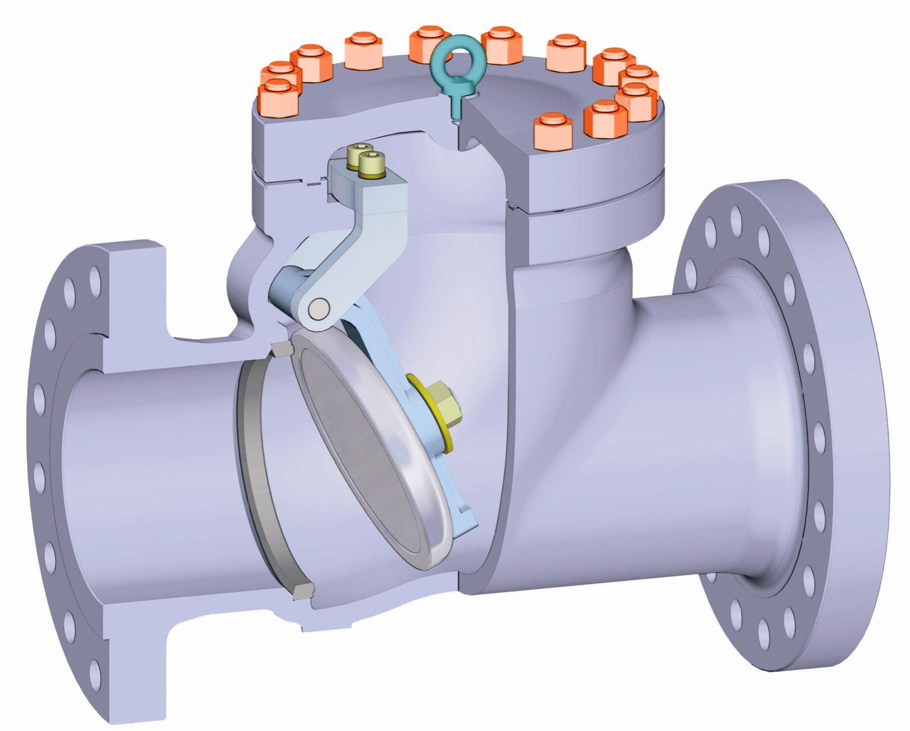
ANSI CLASS 150 ~ 2500
FEATURES
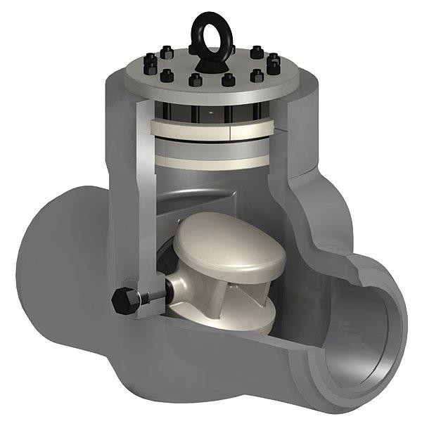
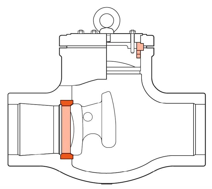
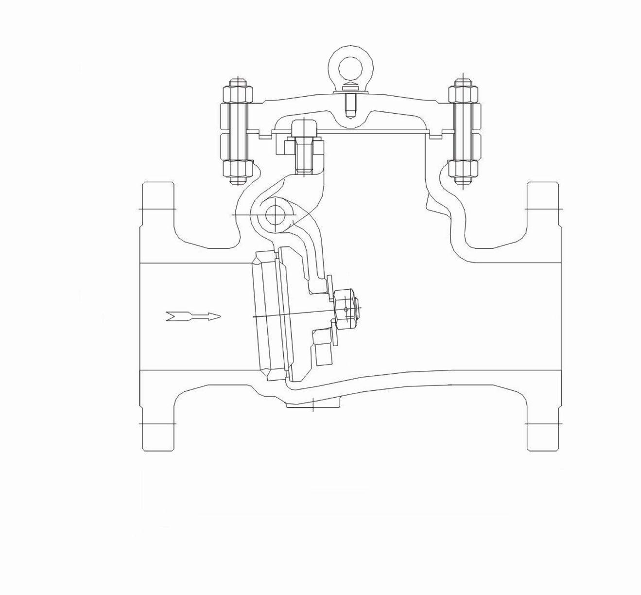
• Bolted or pressure seal bonnet
• Swing disc
APPLICABLE STANDARDS
• Valves designed to ASME B16.34 and API 594/API 6D
• Valves tested to API Std. 598/API 6D/ISO 5208
• Face-to-face to ANSI B16.10
• Flanged ends to ANSI B16.5
• Butt-welding ends to ANSI B16.25
• Trim and seating surface as per API 600 standard.
MATERIAL LIST
9
6
5
material is according to
Eye bolt supplied in larger sizes & higher classes.
1 410 F6 410 (13Cr) (200-275 HBN) F6 (13Cr) (200 HBN) 410 (13Cr) (250 HBN min) 13Cr-0.75Ni-1Mn
2 304 304 304 304 (18Cr-8Ni) 304 (18Cr-8Ni)
3 310 310 (25Cr-20Ni) 310 (25Cr-20Ni) 310 (25Cr-20Ni)
4 410 Hard F6H 410 (13Cr) (200-275 HBN) F6 (13Cr) (200-275 HBN) F6 (13Cr) (275 HBN min)
5 410 Full Hard faced F6HF 410 (13Cr) (200-275 HBN) F6+St Gr6 (CoCr Alloy) (350 HBN min) 410+St Gr6 (CoCr Alloy) (350 HBN min)
5a 410 Full Hard faced F6HF 410 (13Cr) (200-275 HBN) F6+Hardf. NiCr Alloy (350 HBN min) 410+Hardf. NiCr Alloy (350 HBN min)
6 410 and Ni-Cu F6HFS 410 (13Cr) (200-275 HBN) Monel 400® (NiCu Alloy) (250 HBN min) Monel 400® (NiCu Alloy) (175 HBN min)
7 410 Very Hard F6HF+ 410 (13Cr) (200-275 HBN) F6 (13Cr) (250 HBN min) F6 (13Cr) (750 HB)
8 410 Hard faced F6HFS 410 (13Cr) (200-275 HBN) 410 (13Cr) (250 HBN min) 410+St Gr6 (CoCr Alloy) (350 HBN min)
8a 410 Hard faced F6HFS 410 (13Cr) (200-275 HBN) F6 (13Cr) (250 HBN min) 410+Hardf. NiCr Alloy (350 HBN min)
19Cr-9.5Ni-2Mn-0.08C
For oil and oil vapors and general services with heat treated seats and wedges. General very low erosive or non-corrosive service between -100°C and 320°C. This stainless steel material lends itself readily to hardening by heat treatment and is excellent for contacting parts such as stems, gates, and discs. Steam, gas & general service to 370°C. Oil & Oil vapor 480°C.
For moderate pressure in corrosive, low erosive service between -265°C and 450°C.
For moderate pressure in corrosive or non corrosive service between -265°C and 450°C.
13Cr-0.75Ni-1Mn Seats 275 BHN min. As trim 1 but for medium pressure and more corrosive service.
13Cr-0.5Ni-1Mn/Co-Cr-A
High pressure slightly erosive and corrosive service between -265°C and 650°C and higher pressure. Premium trim service to 650°C. Excellent for high pressure water and steam service.
13Cr-0.5Ni-1Mn/Co-Cr-A As trim 5 where Co is not allowed.
13Cr-0.5Ni-1Mn/Ni-Cu As trim 1 and more corrosive service.
13Cr-0.5Ni-1M0/13Cr-0.5Ni-1Mo Seats 750 BHN min. As trim 1 but for higher pressure and more corrosive/erosive service.
13Cr-0.75Ni-1Mn/1/2Co-Cr-A
Universal trim for general service requiring long service life up to 593°C. As trim 5 for moderate pressure and more corrosive service. Steam, gas & general service to 540°C. Standard trim for gate valves.
13Cr-0.75Ni-1Mn/1/2Co-Cr-A As trim 5a for moderate pressure and more corrosive service
9 Monel Monel Monel® (NiCu Alloy) Monel 400® (NiCu Alloy) Monel 400® (NiCu Alloy) 70Ni-30Cu
10 316 316 316 (18Cr-Ni-Mo) 316 (18Cr-Ni-Mo) 316 (18Cr-Ni-Mo)
11 Monel Hard faced MonelHFS Monel® (NiCu Alloy) Monel 400® (NiCu Alloy) Monel 400®+St Gr6 (350HBN min)
For corrosive service to 450°C such as acids, alkalies, salt solutions, etc. Very corrosive fluids. Erosive-corrosive service between -240°C and 480°C. Resistant to sea water, acids, alkalies. Has excellent corrosion resistance in chlorine and alkylation service.
For superior resistance to corrosion for liquids and gases which are corrosive to 410 stainless steel up to 455°C. As trim 2 but a higher level of corrosive service. Provides excellent resistance to corrosive media at high temperatures and toughness for service at low temperatures. Low temperature service standard for 316SS valves.
70Ni-30Cu/1/2Co-Cr-A As trim 9 but for medium pressure and more corrosive service.
11a Monel Hard faced MonelHFS Monel® (NiCu Alloy) Monel 400® (NiCu Alloy) Monel 400®+HF NiCr Alloy (350 HBN min) 70Ni-30Cu/1/2Co-Cr-A As trim 9 but for medium pressure and more corrosive service.
12 316 Hard faced 316HFS 316 (Cr-Ni-Mo) 316 (18Cr-8Ni-Mo) 316+St Gr6 (350 HBN min) 18Cr-12Ni-2.5Mo-2Mn1/2Co-Cr-A As trim 10 but for medium pressure and more corrosive service.
12a 316 Hard faced 316HFS 316 (Cr-Ni-Mo) 316 (18Cr-8Ni-Mo)
13
14a Alloy 20 Hard faced Alloy 20HFS Alloy 20 (19Cr-29Ni) Alloy 20 (19Cr-29Ni) Alloy 20 Hardf. NiCr Alloy (350 HBN min)
15
more corrosive service.
FERRITIC STEELS

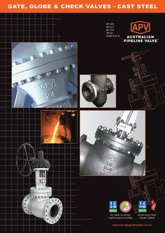
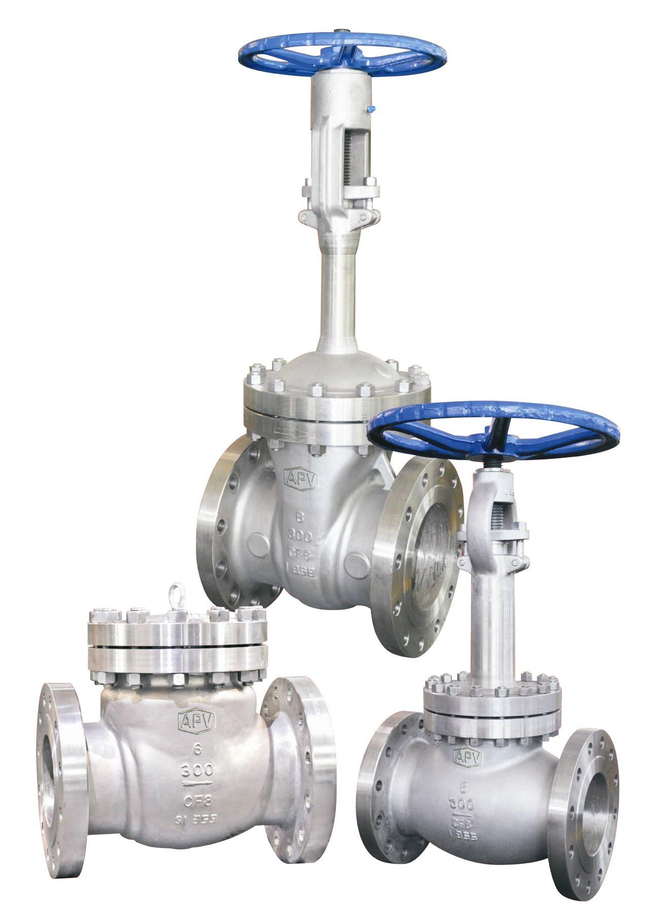
Cast steel valves are designed and manufactured to conform with API, ASTM, ANSI and other applicable internationally recognised standards, to possess all the qualities to meet with stringent requirement criteria of petroleum, petro-chemical and general industrial applications.

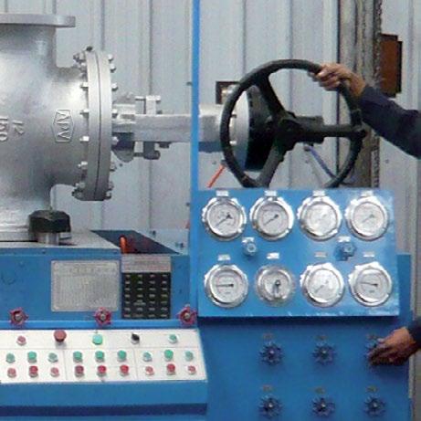
Valves are tested in accordance with applicable API standards. Full traceability is maintained.
Valves offer the option of hard facing on the wedge (disc) and seating areas.
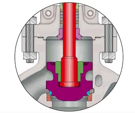
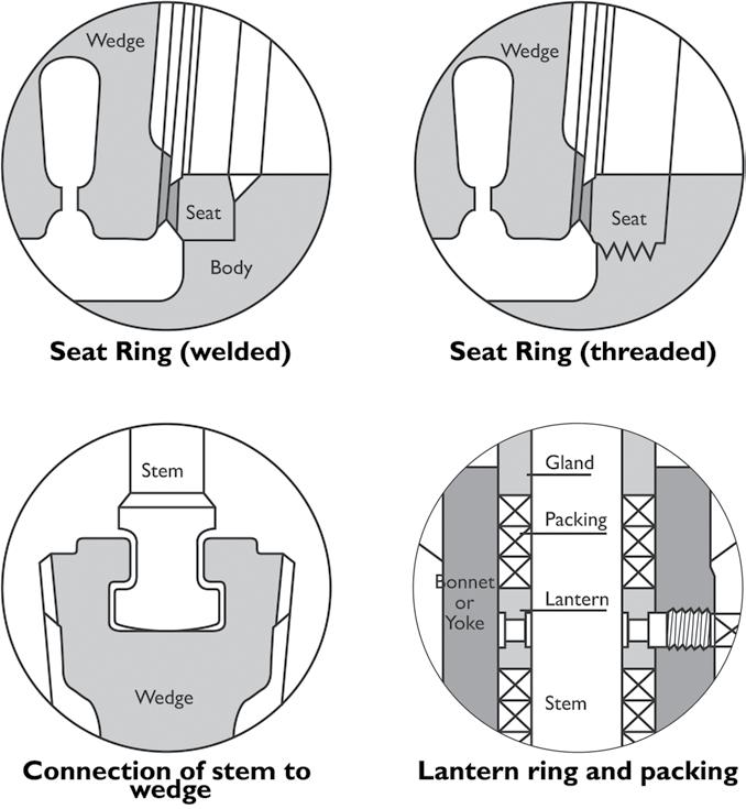
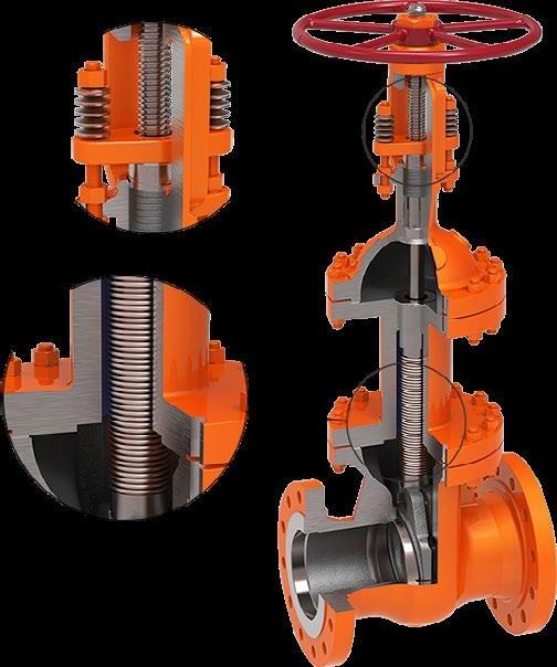
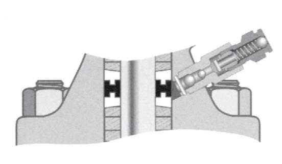
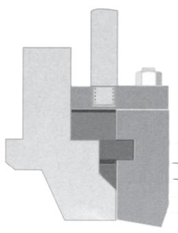
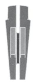
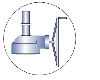
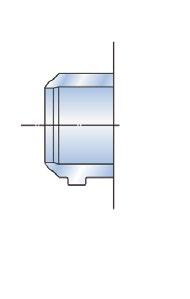
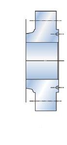
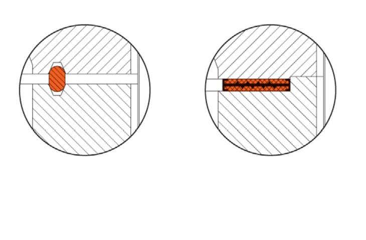
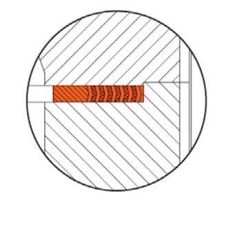
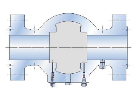
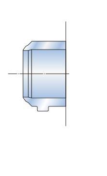
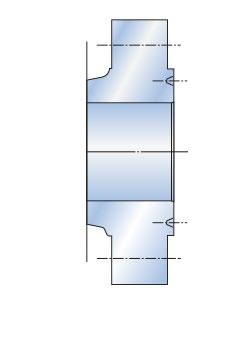
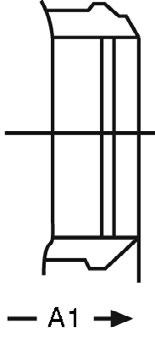
Gate Valves are optionally available with lantern rings. These rings along with double packing provide a leak-off connection. Alongside are illustrations of lantern rings as well as disc connection. Fugitive emission packing sets do normally need a lantern ring.
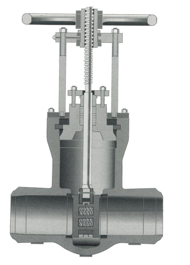
APV offers fugitive emission service valves on special request. The valves comply with environmental protection requirements. APV fugitive emission valves are designed, manufactured and tested to meet less than 100ppm with packing conforming to API 622 and valve design tested to API 624 and ISO 15848-1. Furthermore, optional live-loading of packing bolts is available. Two sets of belleville plate springs maintain a permanent packing stress of 24,000-28,000 kPa. Live-loading extends low emission service life especially in service with high pressure/temperature transients.
The stem on all APV fugitive emission service valves is surface finished to ≤Ra 0.80 µm. Straightness and roundness are precisely controlled. The stuffing box has a maximum ≤Ra 3.2 µm surface finish. Cylindricity and verticality are precisely controlled.
Shell wall thickness and general valve design specifications
API 600 (Gate Valves)
API 603 (Gate Valves)
API 594 (Check Valves)
API 623 (Globe Valves)
B16.34

B16.10 Flanged end dimensions
end dimensions
B16.5*
B16.25
Live Loading is an addition of spring washers to the gland studs to maintain the packing load of the valve over time.
The bellow seal replaces the dynamic sealing system of a stem packing by a static sealing system between the valve bonnet and the valve stem bottom. It prevents the valve from the risk of leakage from the valve packing for VOC or toxic services.
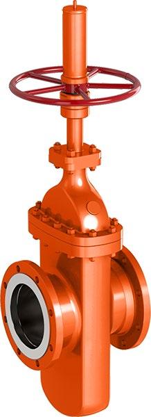
Gate valves are used for bi-directional shut off applications where minimum pressure drop is required. They are not designed for throttling service. Gear operators, actuators, by-passes, actuators etc, can be fitted on request. Parallel slide style also available.
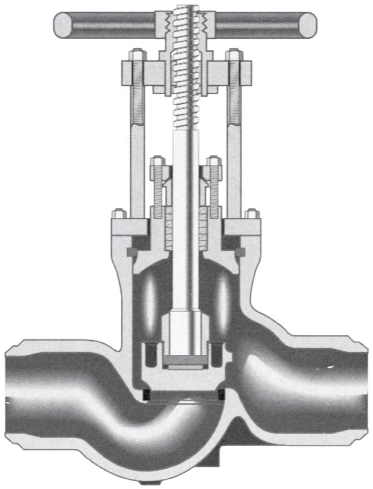
Globe valves are ideal for throttling and shut off. They can be used for shut off service, but do have a higher pressure drop and seat leakage allowance than gate valves. Globe valves should not be used for prolonged throttling at less than 10% open. Gearboxes, actuators, bypasses etc, can be fitted.
Valves must only be used in operating conditions within the correct ANSI pressure-temperature ratings for valve class rating and body/bonnet material.
Only use valves within the correct temperature limitations of their construction. Temperature limitations of body/bonnet materials, trim, bolting, packing and gaskets must all be considered.
Stop check valves are combination globe and check valves. In the open position, they function as a lift check valve. In the closed position, they are seated by manually closing the stem like a globe valve. Stop check valves must be installed vertically (in a horizontal pipeline). They provide positive shutoff in either direction when the stem is in the closed position. Right angle and inclined ‘Y’ style are also available.
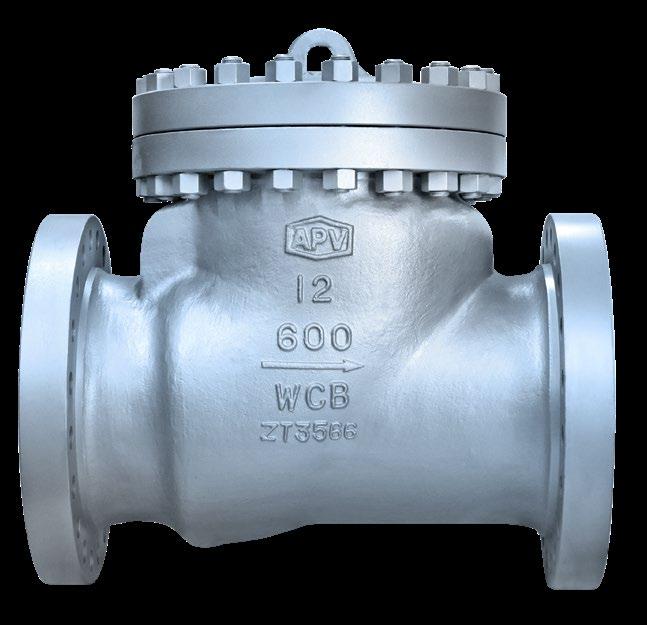
Swing check valves are used to prevent flow reversal. They are suitable for service in horizontal or upwards vertical. They have low pressure drop and are best suited for moderate velocity applications. Either too low a line velocity or too high a velocity can damage valve internals and shorten valve life hence correct size selection is important. Service in systems involving rapid and frequent flow reversals, pulsation or turbulent flow should be avoided. Also API 6D full opening (piggable) type available on request.
APPLICATIONS (150LB ~ 600LB)
Extended Service
Application Requirements
Function
Fugitive Emission
High Flow Capacity
Low Torque
Reduced Maintenance
Diverting
On/Off
Throttling
Abrasive Slurries
Clean Liquids & Gases
Corrosive Liquids & Gases
Dirty Liquids & Gases
Media
Dry Material
Fibrous Slurries
Hazardous Liquids & Gasses
Scaling Liquids & Slurries
Vacuum Service
Viscous Liquids
Recommended
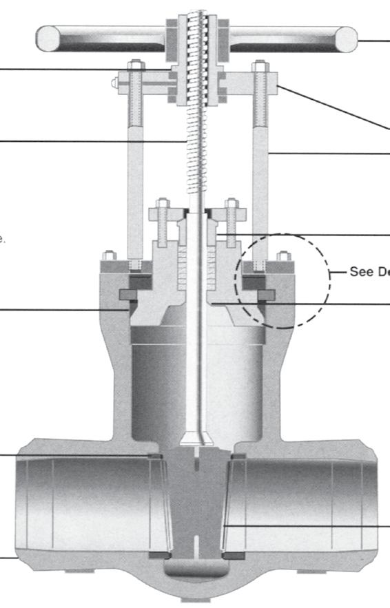
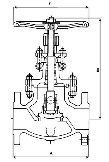
Full body wedge guides allow correct wedge alignment. Yoke sleeve with bearings reduce torque for easy operation. Seat rings allow easy access for maintenance and packing replacement is simple. Seat face 13Cr hardfaced, ground and lapped to a Ra 0.4~0.8 µm finish. Wedge is ground and lapped to a Ra 0.4~0.8 µm finish and tightly guided to prevent dragging and seat damage. Non-rotating stem with precision Acme threads and burnished finish. Rotating stem nut is austenitic ductile iron Gr. D-2C renewable.
API 600 and ANSI B16.34. Dimensions to ANSI B16.10 and ISO 5727. Stuffing box smoothness ≤Ra 3.2 µm superior to API 600. Stem smoothness ≤Ra 0.80 µm as per API 600.
All gate valves are available with optional PTFE seat rings. The moulded PTFE ring is bonded into a seat ring groove in the face for maximum service life. This design is excellent for lower temperature service where tight shutoff is required.
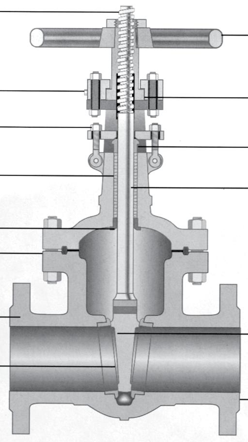
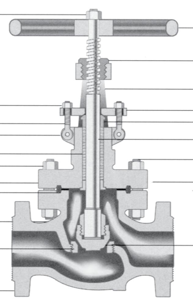
Handwheel
Rising Stem - provides open-close indication 3. Grease Fitting - to minimise wear and operating torque 4. Yoke Sleeve - furnished in ductile Ni-resist or aluminium-bronze for low torque operation
Parallel slide style also available, see page 20, 84 - 88 and also see APV Steamco Catalogue
5. Swing Bolt - easier maintenance and packing replacement
6. Gland - flange is self-aligning to eliminate stem damage
7. Stuffing Box
8. Stem - upset forge T-head stems to eliminate possibility of a bent stem jamming the valve
9. Backseat - provides back-up stem seal
10. Bonnet Joint
11. Body - full ported, heavy wall body API 600 wall thickness 12. Wedge - heavy pattern. Available in solid & flex wedge
Seat Ring - full ported rings for easy maintenance
End Connections - flanged or
Seat rings are easily accessible for repair or replacement. Australian Pipeline Valve globe valves are for services requiring frequent operation for on-off isolation service as well as throttling. Never attempt throttling at under 20% of stem travel. Closer throttling, can result in higher pressure drops which may cause excessive velocities or cavitation and could cause vibration or high noise levels resulting in damage to the valve or adjacent components/structure.
Heavy construction provides years of reliable service.
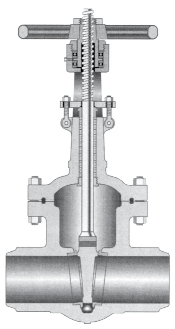
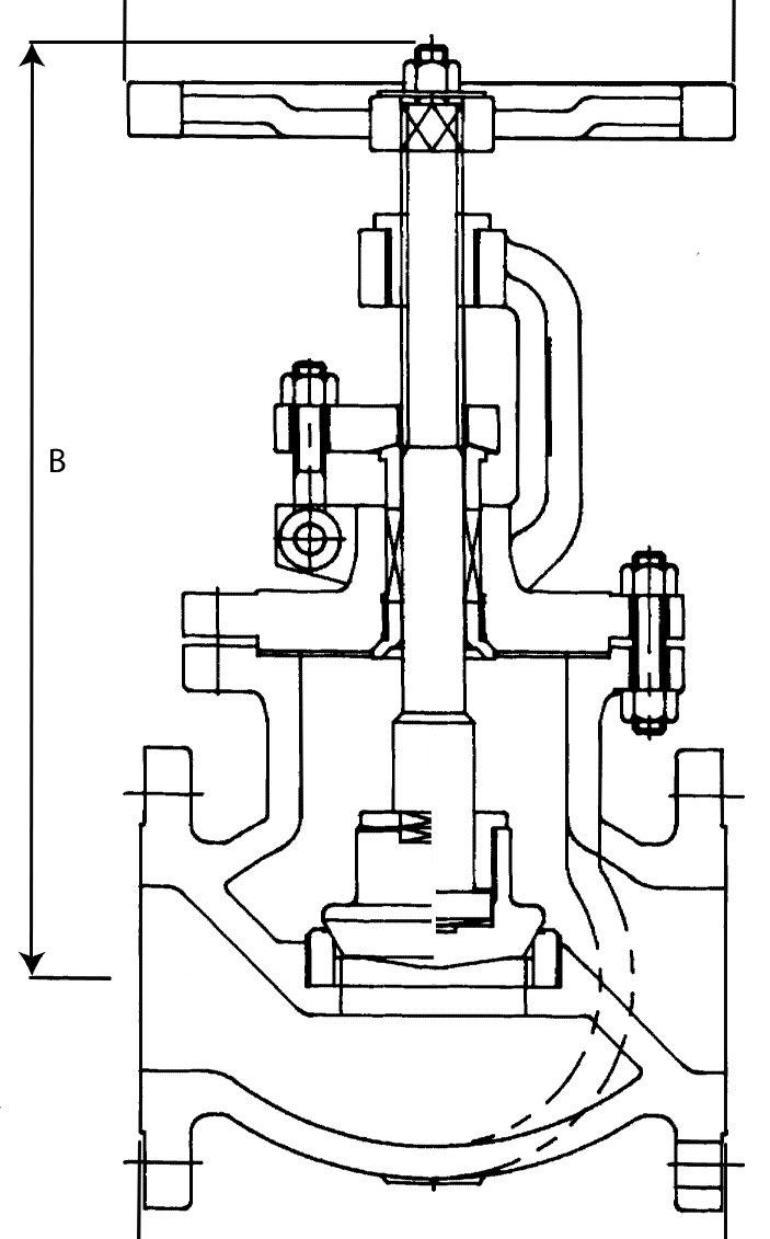
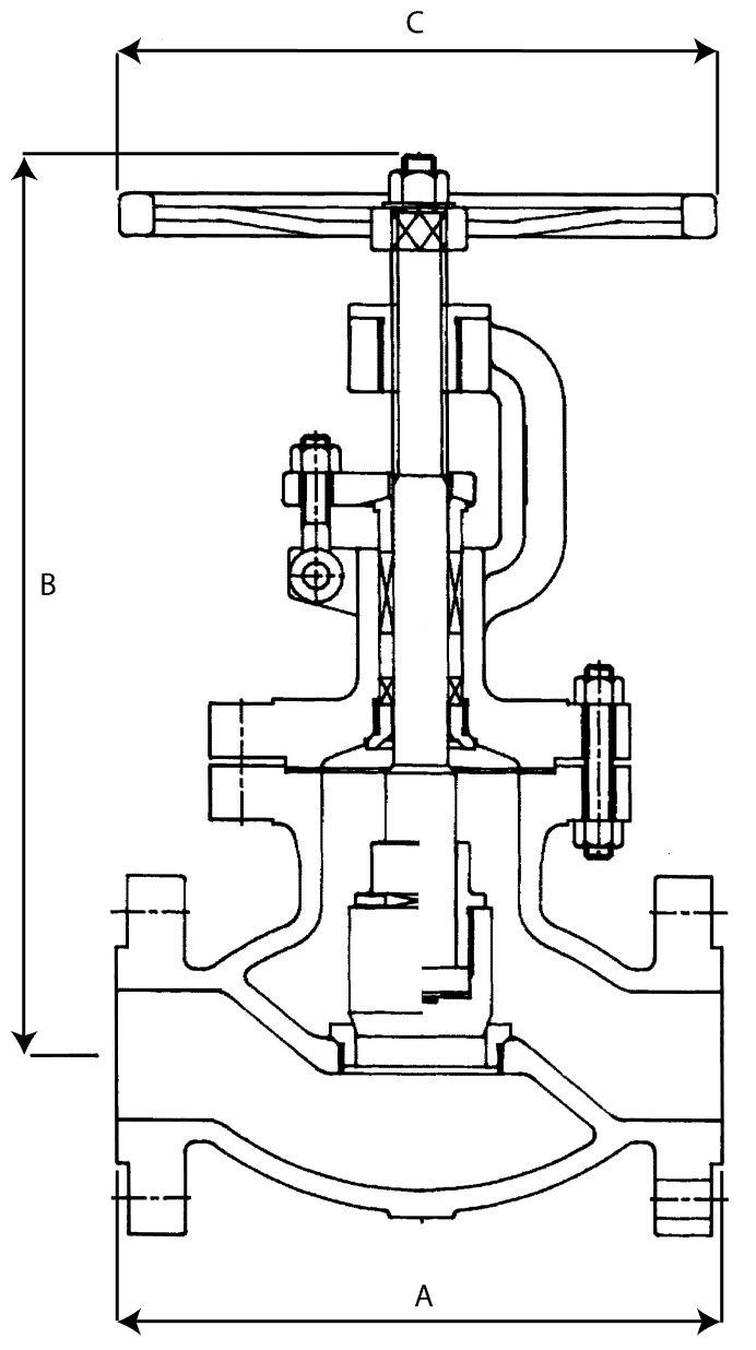
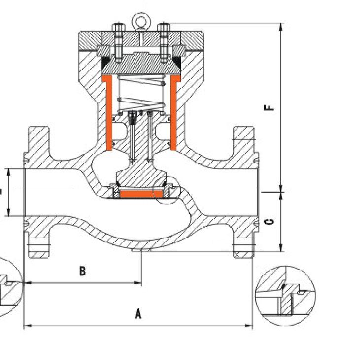
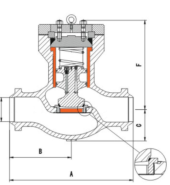
Available in bolted and pressure seal bonnet, outside screw and yoke, rising stem with ball or plug type disc, and have flanged or butt weld ends. Screw down non-return (Stop check) also available. Stem with precision Acme threads and burnished finish. Valve suitable for horizontal installation. Conical seating surfaces 13Cr hardfaced/stellite, ground and lapped to a Ra 0.4~0.8 µm finish. Tapered plug type disc as standard. Body guided disc on larger sizes, and higher classes on smaller sizes, accurately mates the hardfaced surface of the disc with the surface of the seat. Body and bonnet joint accurately machined. Fully enclosed gasket. Rotating stem nut, austenitic ductile iron Gr. D-2C, renewable in-line.
To ASME B16.34 / API 623. Dimensions to ASME B16.10 and ISO 5752. Wall thickness, stem smoothness and stuffing box finish complies with API 623. APV stuffing box smoothness ≤Ra 3.2 µm superior to API 623 / API 600. Stem smoothness ≤Ra 0.80 µm as per API 623.
1. Yoke Sleeve - furnished in aluminium-bronze to reduce torque. Larger sizes furnished with bearings 2. Handwheel 3. Swing Bolts - easier maintenance
4. Gland - self-aligning to eliminate stem damage
5. Stuffing Box
6. Stem - heavy duty
7. Backseat - provides back-up stem seal
8. Bonnet Joint - ring joint or spiral according to ANSI class
9. Seat Rings - separate heavy duty, full ported rings for easy maintenance
10. Disc - heavy duty disc plug design
11. End Connections - flanged or butt weld ends
12. Body - full ported, with API 600 / API 623 heavy wall thickness
Stem guide - (Optional) for reduced packing
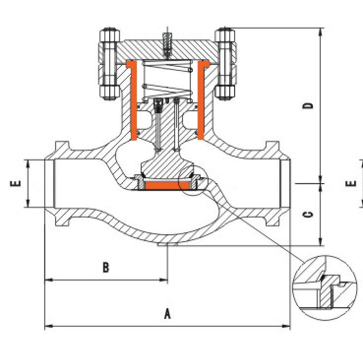
623 Guided disc style (Non Rotating Stem Version)


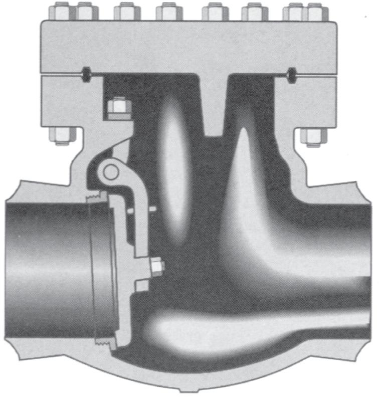
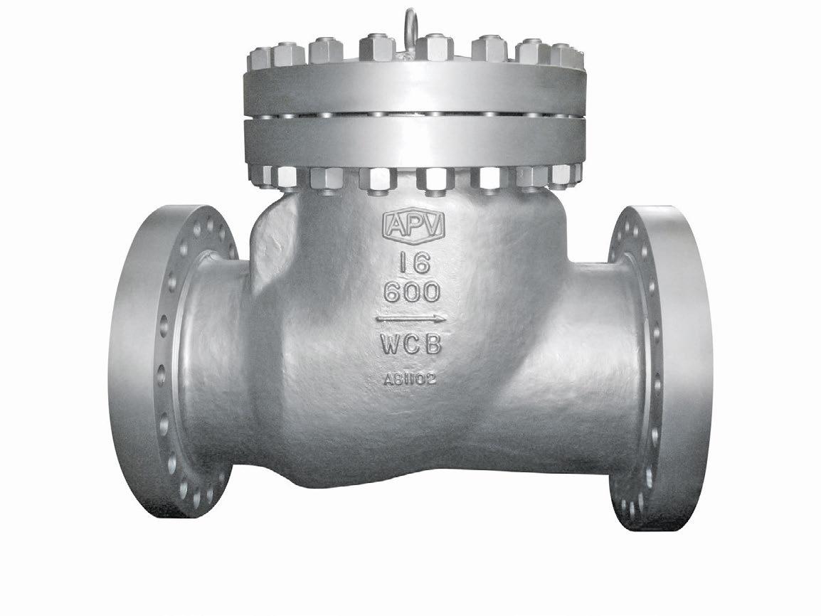
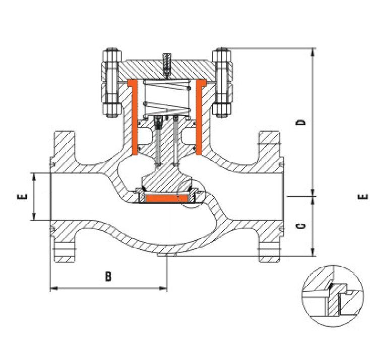
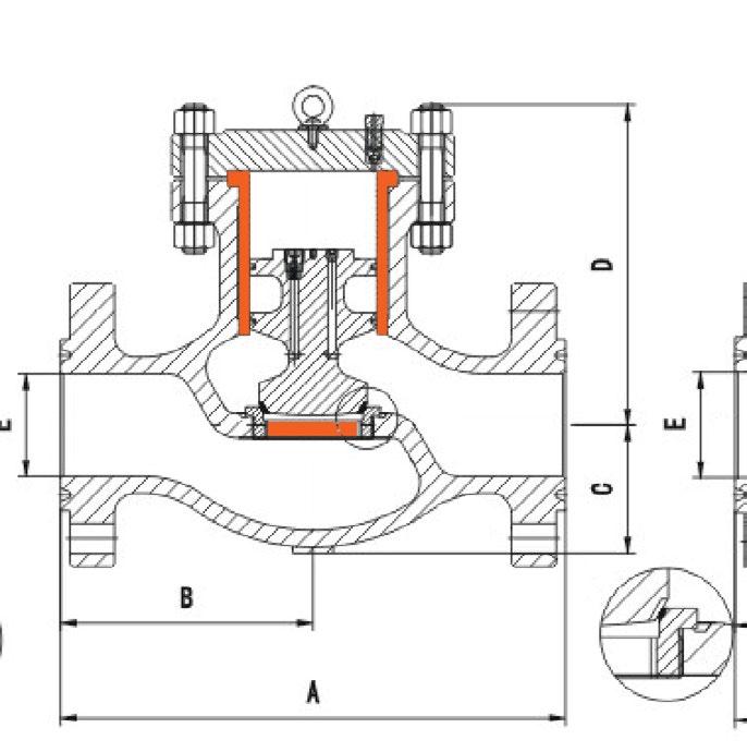
Australian Pipeline Valve valves are designed to provide fast valve action and maximum life. All valves are full ported, have full API 600/API 594 wall thickness, and meet the requirements of ANSI B16.34. Full opening API 6D (piggable) type also available on request.
ASME B16.34 / API 594 /API 6D as applicable.
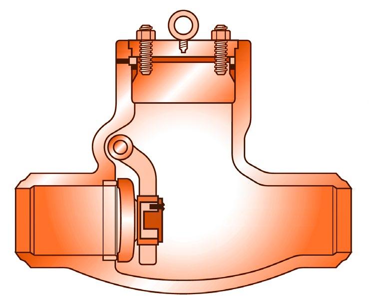
Check valves are designed to close quickly in either horizontal or vertical (flow up) pipe runs. The body seat ring is installed on a 3° angle. This allows our check valve to close even when installed in horizontal pipe run with no pressure.
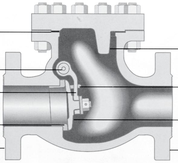
1. Disc Stop - provides positive stop in open position
2. Bonnet Joint - (ring or spiral according to class)
3. Hinge Pin - solid pin for maximum strength
4. Securing Lugs - allow disc to seat freely and prevent disc spinning
5. Hinge - designed to withstand shock and load of quick closing
6. Disc - disc is bolted and pinned to hinge; ground seating surface is mated to seat ring for positive shut off
7. Seat Ring - Full port seal welded or screwed
8. End Connections - flanged or buttweld
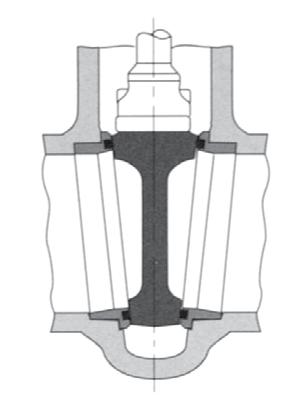
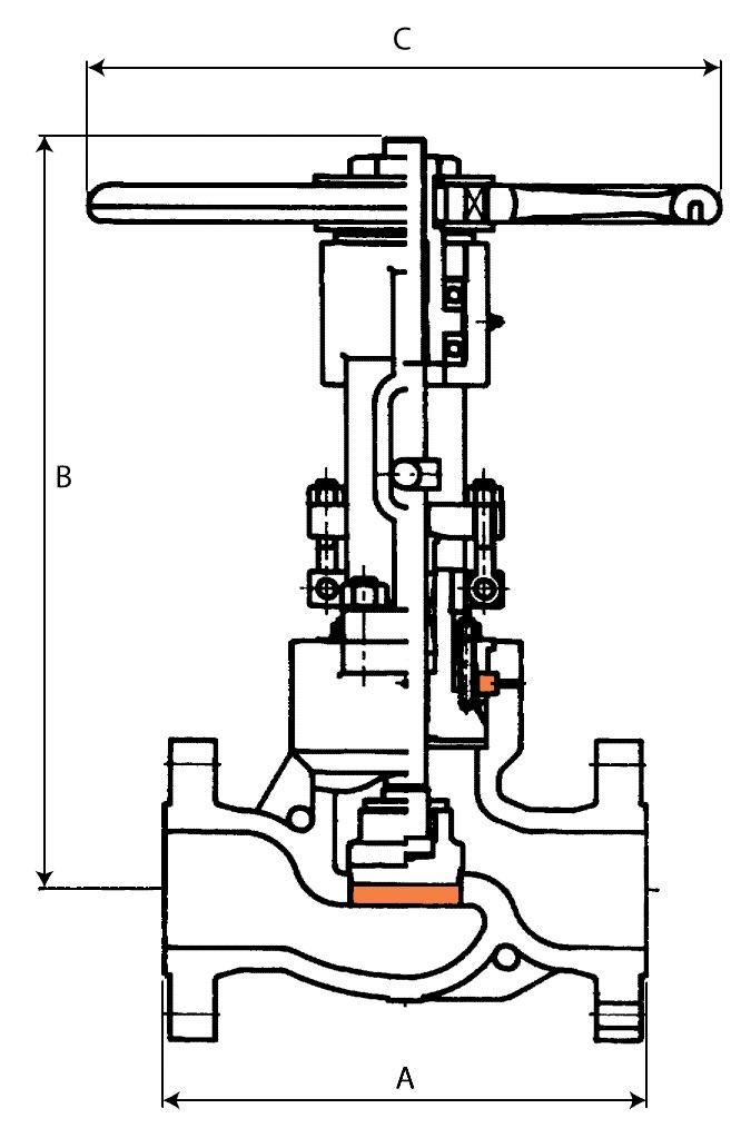
The wedge is a one piece, fully guided wedge. Available in flex wedge and solid wedge. (Flexible wedge allows the seating faces to move to compensate for thermal expansion). Wedging actions allows a tight seal even in low differential pressure services. Flexible wedge construction resists wedge sticking in service where the valve may be closed when hot and opened when cold. Seating surfaces are hardfaced for long life.
Parallel slide also available, see page 20, 84 - 85 and also see APV Steamco Catalogue.
1. Yoke Sleeve - aluminium-bronze yoke sleeve has thrust bearings to minimise torque
2. Hand Wheel - (or gear in larger sizes)
3. Yoke - offering ease of maintenance
4. Stem - The design allows the wedge to self-align, eliminating the possibility of jamming the wedge
5. Gland - two piece, self-aligning gland eliminates cocking. Swing out bolting facilitates maintenance
6. Back Seat - Integral, hardfaced
7. Pressure Seal - retaining ring and mild steel silver plated/SS/ SS+GRP gasket to aid disassembly and provide maximum seal
8. Seat Ring - hardfaced seat rings are welded to body. Tapered design provides clear flow path
9. Wedge - one-piece, fully guided. Parallel seat also available
Body - streamlined flow path minimises pressure drop.
Bonnet
Ring
Normally utilised for shut off service but are not recommended for throttling. Gate valves are normally installed in horizontal pipe runs with the valve stem vertically up. They can be installed in horizontal or vertical pipe runs. After closing with sufficient force, the stem should be backed off slightly (1/8 turn) to relieve stem load. Parallel Slide Valves have self aligning discs with no wedging force and react freely to thermal changes. The design also ensures uniform seat wear and ease of maintenance. Parallel Slide Gate Valves are ideal where high differential pressure or thermal expansion may cause sticking of wedge to gate in traditional gate valves.
The torque arm design guides and centralises the stem and prevents stem movement which reduces wear on packing rings & enables better sealing as well as reducing torque. Only the stem nut rotates. The arm also provides visual stem position indication & can be interfaced with position switches. Optional live loaded packing system is shown.
1. Yoke Sleeve - aluminium-bronze yoke sleeve with thrust bearings for ease of opening
2. Actuation - Low torque seating design reduces actuation costs
3. Yoke - designed to offer ease of maintenance
4. Stem - Threaded into disc housing and also pinned
5. Gland - two piece, self-aligning gland eliminates cocking. Swing out bolting facilitates maintenance
6. Back Seat - Integral, hardfaced
7. Pressure Seal - retaining ring and mild steel silver plated/SS/SS+GRP gasket to aid disassembly and provide maximum seal
8. Seat Ring - hardfaced seat rings are welded to body and are designed for ease of maintenance
9. Discs - Spring loaded discs are self-aligning and reduce actuator torque requirements 10. Integral Stop - Integral stop positions for reliable
Australian Pipeline Valve Globe valves are installed with pressure and flow under the disc. Globe valves are suitable for most throttling applications; they should not be used for throttling at less than 10% open. Stop Check Valves have a guided loose disc allowing the valve to act as a combination globe valve and check valve.
API 622 & ISO 15848-1
Fugitive Emission Certified
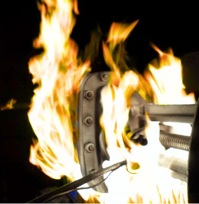
API 607-7th & ISO 10497
Firesafe Certified
seat and body life as well as ensuring positve shut-off and low closing torque.
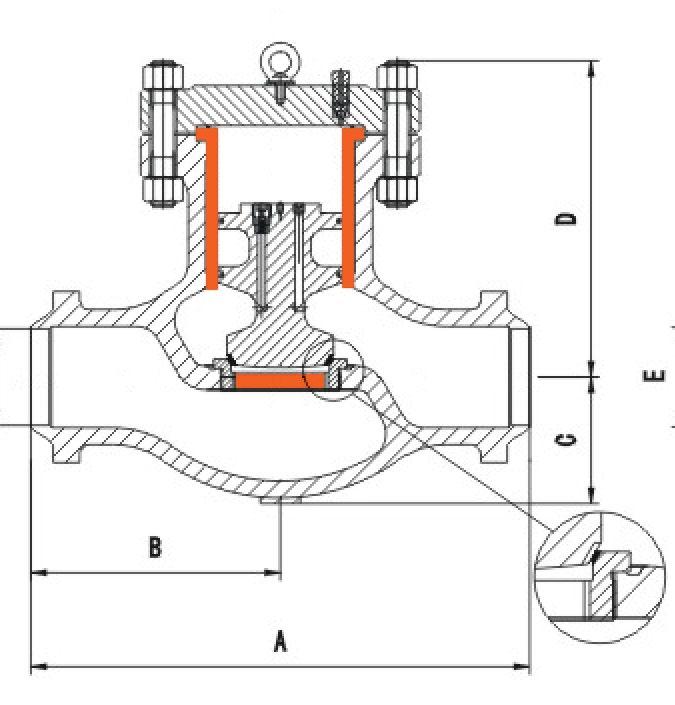
The torque arm design guides and centralises the stem and prevents stem movement which reduces wear on packing rings & enables better sealing as well as reducing torque. Only the stem nut rotates. The arm also provides visual stem position indication & can be interfaced with position switches. Optional live loaded packing system is shown.
1. Yoke Sleeve - aluminium-bronze yoke sleeve minimizes operating torque. Larger sizes have needle bearing type thrust bearings
2. Actuation - Manual handwheel gear operator or actuated 3. Yoke - designed to offer ease of maintenance
4. Stem - precision-ground stem has upset tee-head for reliable stem/wedge connection
5. Gland - two piece, self-aligning gland eliminates cocking. Swing out bolting facilitates maintenance
6. Back Seat - Integral, hardfaced
7. Pressure Seal - uncomplicated design has segmented retaining ring and mild steel silver plated/SS/SS+GRP gasket to aid disassembly and provide maximum bonnet seal
8. Hardened Seating Surfaces - both disc and body seating surfaces are hard faced for maximum service life
9. Disc - fully body guided for positive seating
10. Body - Full port ‘s’ pattern design available to minimise pressure drop
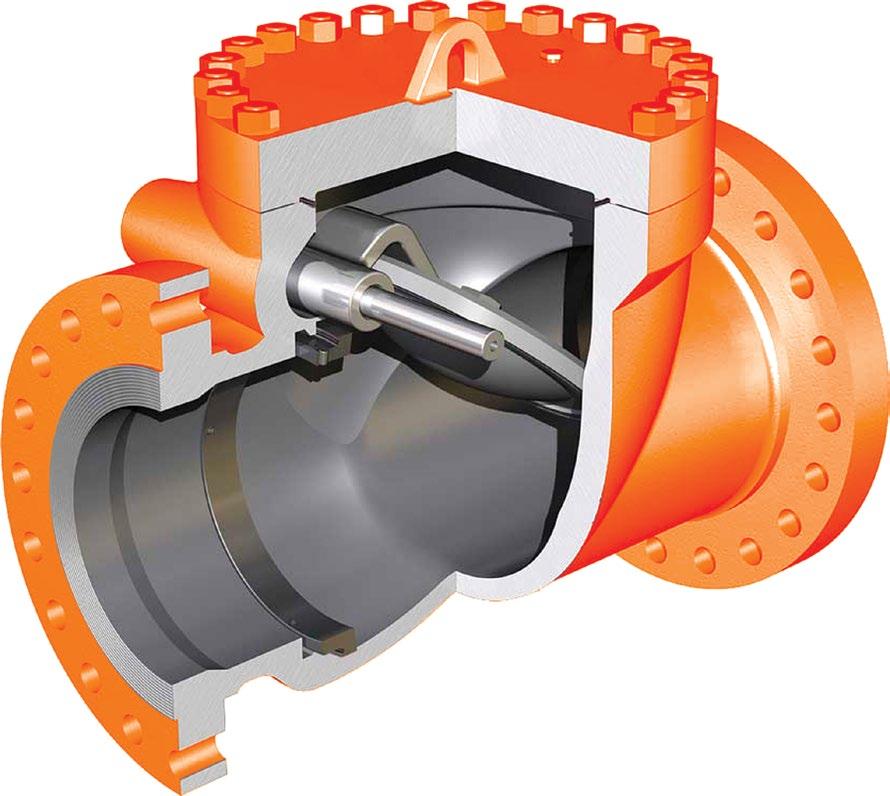
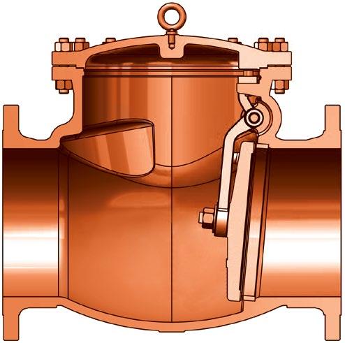
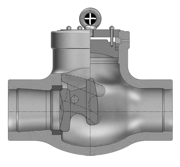
Australian Pipeline Valve Check valves are installed with pressure and flow under the disc.
Reduced maintenance is assured because the disc is the only moving part and is designed to minimise flutter in the closed position, thus reducing wear on the pivot pin, disc, and seat.
Loss of head is minimised by the balanced disc and its ‘aerofoil’ design. Short distance of travel, combined with a balanced disc allows rapid closure while minimising slamming.
Drip tight seating is accomplished over the full pressure range because a slight clearance at the pivot pin assures complete seating between the disc ring and body ring.
The hinge pin located near the center of gravity allows the conical seating face of the disc to move out and into the seat rapidly without sliding or wear. The disc pivots through a small arc preventing backflow and ‘water hammer’. Superior tightness - conical, lapped-in hardfaced seating is self aligning. Valve can be used in horizontal but also even in vertical piping with flow up.
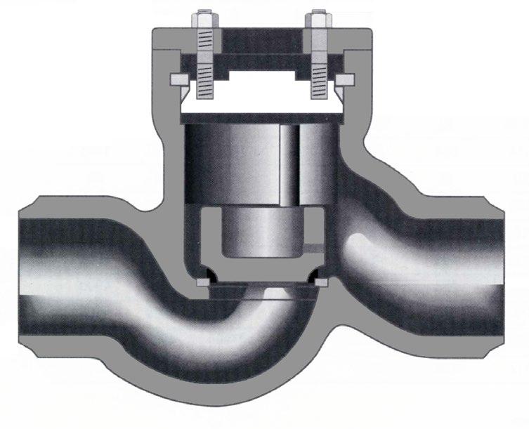
Piston Lift Check valves are generally used in applications where pressure drop through the valve is not critical, although APV piston check valves have a relatively low pressure drop. available in horizontal, right angle, Y patterned (inclined) and vertical designs. Excellent for low or pulsating flows with good to moderate sealing capability. APV offers fully guided disc through the total travel.
Piston Lift Check Valves may be equipped with equaliser lines to vent the bonnet area above the disk and eliminate any dash-pot effect during rapid operation. An aspirator is also available with an adjustable valve to control disc opening and closing speed.
Description
Body
Specs.
Steel A216 Gr. WCB
Bonnet Carbon Steel A216 Gr. WCB
Disc / Facing Stainless Steel A216 Gr. WCB+410SS/CR13 or Stellite/HF
Stem Stainless Steel A276 Gr.410 or A182 Gr. F6a/CR13
Hand Wheel Ductile Iron A536 Gr. 65-45-12
Seat / Facing Stainless Steel/HF A105/F6a+410SS/CR13/Stellite
Back Seat Ring Stainless Steel A276 Gr. 410 or A182 Gr. F6a
Yoke Sleeve Ductile Iron or Bronze A439 Gr. D2C or B62
Sleeve Gland Carbon Steel A216 Gr. WCB
Gland Flange Carbon Steel A105
Gland Ring Stainless Steel A182 Gr. F6a Wheel Nut Carbon Steel A105
Bonnet Bolt Alloy Steel A193 Gr. B7/B7M
Bonnet Nut Alloy Steel A194 Gr. 2H/2HM
Gland Bolt Alloy Steel A193 Gr. B7
Gland Nut Alloy Steel A194 Gr. 2H
Gland Bolt Pin Alloy Steel A108 Gr. 1020
Bearing - Thrust Ball
Grease Nipple Carbon Steel A307 Gr. B
Set Screw Carbon Steel A307 Gr. B
Name Plate Stainless Steel 304/AL
Packing Asbestos Free Reinforced Graphite
Gasket 316/Graphite Reinforced Graphite 316 Tanged
Description Material Specs.
Body Carbon Steel A216 Gr. WCB
Bonnet Carbon Steel A216 Gr. WCB
Disc / Facing Stainless Steel A216 Gr. WCB+410SS/CR13 or Stellite/HF
Stem Stainless Steel A276 Gr.410 or A182 Gr. F6a/CR13
Hand Wheel Ductile Iron A536 Gr. 65-45-12
Seat / Facing Stainless Steel/HF A105/F6a+410SS/CR13/Stellite
Back Seat Ring Stainless Steel A276 Gr. 410 or A182 Gr. F6a
Yoke Sleeve Ductile Iron or Bronze A439 Gr. D2C or B62
Sleeve Gland Carbon Steel A216 Gr. WCB
Gland Flange Carbon Steel A105
Gland Ring Stainless Steel A182 Gr. F6a
Wheel Nut Carbon Steel A105
Bonnet Bolt Alloy Steel A193 Gr. B7/B7M
Bonnet Nut Alloy Steel A194 Gr. 2H/2HM
Gland Bolt Alloy Steel A193 Gr. B7
Gland Nut Alloy Steel A194 Gr. 2H
Gland Bolt Pin Alloy Steel A108 Gr. 1020
Bearing - Thrust Ball
Grease Nipple Carbon Steel A307 Gr. B
Set Screw Carbon Steel A307 Gr. B
Name Plate Stainless Steel 304/AL
Packing Asbestos Free Reinforced Graphite
Gasket Spiral Wound 304/316 Graphite filled
DIMENSIONS (MM)
For 1/2” to 1” dimensions see page 58 and overview brochure. For RTJ & 5” dimensions see overview brochure.
1655 2320
For CF8/CF8M 300Lb gate see page 58. * For Buttweld weights see overview brochure.
Description Material Specs.
Body Carbon Steel A216 Gr. WCB
Bonnet Carbon Steel A216 Gr. WCB
Disc / Facing Stainless Steel A216 Gr. WCB+410SS/CR13 or Stellite/HF
Stem Stainless Steel A276 Gr.410 or A182 Gr. F6a/CR13
Hand Wheel Ductile Iron A536 Gr. 65-45-12
Seat / Facing Stainless Steel/HF A105/F6a+410SS/CR13/Stellite
Back Seat Ring Stainless Steel A276 Gr. 410 or A182 Gr. F6a
Yoke Sleeve Ductile Iron or Bronze A439 Gr. D2C or B62
Sleeve Gland Carbon Steel A216 Gr. WCB
Gland Flange Carbon Steel A105
Gland Ring Stainless Steel A182 Gr. F6a
Wheel Nut Carbon Steel A105
Bonnet Bolt Alloy Steel A193 Gr. B7/B7M
Bonnet Nut Alloy Steel A194 Gr. 2H/2HM
Gland Bolt Alloy Steel A193 Gr. B7
Gland Nut Alloy Steel A194 Gr. 2H
Gland Bolt Pin Alloy Steel A108 Gr. 1020
Bearing - Thrust Ball
Grease Nipple Carbon Steel A307 Gr. B
Set Screw Carbon Steel A307 Gr. B
Name Plate Stainless Steel 304/AL
Packing Asbestos Free Reinforced Graphite
Gasket Metal Ring Joint or Spiral Wound SS Graphite filled
Description Material Specs.
Body Carbon Steel A216 Gr. WCB
Bonnet Carbon Steel A216 Gr. WCB
Disc / Facing Stainless Steel A216 Gr. WCB+410SS/CR13 or Stellite/HF
Stem Stainless Steel A276 Gr.410 or A182 Gr. F6a/CR13
Hand Wheel Ductile Iron A536 Gr. 65-45-12
Seat / Ring Carbon Steel/HF A105/F6a+410SS/CR13/Stellite
Back Seat Ring
Stainless Steel A182 Gr. F6a
Yoke Sleeve Ductile Iron or Bronze A439 Gr. D2C or B62
Sleeve Gland Carbon Steel A216 Gr. WCB
Gland Flange Carbon Steel A105
Gland Ring Stainless Steel A182 Gr. F6a
Wheel Nut Carbon Steel A105
Bonnet Bolt Alloy Steel A193 Gr. B7/B7M
Bonnet Nut Alloy Steel A194 Gr. 2H/2HM
Gland Bolt Alloy Steel A193 Gr. B7/B7M
Gland Nut Alloy Steel A194 Gr. 2H.2HM
Gland Bolt Pin Alloy Steel A108 Gr. 1020
Bearing - Thrust Ball
Grease Nipple Carbon Steel A307 Gr. B
Set Screw Carbon Steel A307 Gr. B
Name Plate Stainless Steel 304/AL
Packing Asbestos Free Reinforced Graphite
Gasket Metal Ring Joint or Spiral Wound SS, Graphite filled
Description Material Specs.
Body Carbon Steel A216 Gr. WCB
Bonnet Carbon Steel A216 Gr. WCB
Disc Facing Stainless Steel A216 Gr. WCB+410SS/CR13 or Stellite/HF
Stem Stainless Steel A276 Gr.410 or A182 Gr. F6a/CR13
Hand Wheel Ductile Iron A536 Gr. 65-45-12
Seat / Ring Carbon Steel/HF A105/F6a+410SS/CR13/Stellite
Back Seat Ring Stainless Steel A182 Gr. F6a
Yoke Sleeve Ductile Iron or Bronze A439 Gr. D2C or B62
Sleeve Gland Carbon Steel A216 Gr. WCB
Gland Flange Carbon Steel A105
Gland Ring Stainless Steel A182 Gr. F6a
Wheel Nut Carbon Steel A105 Zn. Plating
Bonnet Bolt Alloy Steel A193 Gr. B7/B7M
Bonnet Nut Alloy Steel A194 Gr. 2H/2HM
Gland Bolt Alloy Steel A193 Gr. B7/B7M
Gland Nut Alloy Steel A194 Gr. 2H/2HM
Gland Bolt Pin Alloy Steel A108 Gr. 1020
Bearing - Thrust Ball
Grease Nipple Carbon Steel A307 Gr. B
Set Screw Carbon Steel A307 Gr. B
Name Plate Stainless Steel 304/AL
Packing Asbestos Free Reinforced Graphite
Gasket Metal Ring Joint or Spiral Wound SS Graphite filled
Body Carbon Steel A216 Gr. WCB
Bonnet Carbon Steel A216 Gr. WCB
Disc / Facing Stainless Steel A216 Gr. WCB+410SS/CR13/Stellite Stem Stainless Steel A276 Gr.410 or A182 Gr. F6a/CR13
Hand Wheel Ductile Iron A536 Gr. 65-45-12
Seat / Ring Carbon Steel/HF A105/A182 F6a + Stellite
Yoke Sleeve Ductile Iron or Bronze A439 Gr. D2C or B62
Sleeve Gland Carbon Steel A216 Gr. WCB
Gland Flange Carbon Steel A105
Gland Ring Stainless Steel A182 Gr. F6a Wheel Nut Carbon Steel A105
Bonnet Bolt Alloy Steel A193Gr. B7/B7M
Bonnet Nut Alloy Steel A194 Gr. 2H/2HM
Gland Bolt Alloy Steel A193 Gr. B7
Gland Nut Alloy Steel A194 Gr. 2H
Gland Bolt Pin Alloy Steel A108 Gr. 1020
Bearing Assembly Thrust Ball
Grease Nipple Carbon Steel + ZP A307 Gr. B
Set Screw Carbon Steel A307 Gr. B
Name Plate Stainless Steel 304/AL
Packing Asbestos Free Reinforced Graphite
Gasket Soft Metal Ring/SS Plated
DIMENSIONS (MM)
Description Material Specs.
Body Carbon Steel A216 Gr. WCB
Bonnet Carbon Steel A216 Gr. WCB
Disc / Facing Stainless Steel A216 Gr. WCB+410SS/CR13/Stellite
Stem Stainless Steel A276 Gr.410 or A182 Gr. F6a/CR13
Hand Wheel Ductile Iron A536 Gr. 65-45-12
Seat / Ring Carbon Steel A105/A182 F6a + Stellite
Yoke Sleeve Ductile Iron or Bronze A439 Gr. D2C or B62
Sleeve Gland Carbon Steel A216 Gr. WCB
Gland Flange Carbon Steel A105
Gland Ring Stainless Steel A182 Gr. F6a Wheel Nut Carbon Steel A105 Zn. Plating
Bonnet
Gland
Bearing Assembly
Grease Nipple
Set
Packing
Gasket Soft Metal Ring/SS Plated
Standards
Face to Face/End to End ANSI B16.10
Flange Dimensions ANSI B16.5 Basic Design* API 600, ANSI B16.34, MSS-SP144 Testing API 598
*Note: 250NB (10”) and over sizes are according to ANSI B16.34
PORT DESIGN DIMENSIONS (MM)
DIMENSIONS (MM)
Description Material Specs.
Body Carbon Steel A216 Gr. WCB
Bonnet Carbon Steel A216 Gr. WCB
Disc / Facing Stainless Steel A216 Gr. WCB+410SS/CR13/Stellite
Stem Stainless Steel A276 Gr.410 or A182 Gr. F6a/CR13
Hand Wheel Ductile Iron A536 Gr. 65-45-12
Seat / Ring Carbon Steel A105/A182 F6a + Stellite
Yoke Sleeve Ductile Iron or Bronze A439 Gr. D2C or B62
Sleeve Gland Carbon Steel A216 Gr. WCB
Gland Flange Carbon Steel A105
Gland Ring Stainless Steel A182 Gr. F6a
Wheel Nut Carbon Steel A105 Zn. Plating
Bonnet Bolt Alloy Steel A193 Gr. B7/B7M
Bonnet Nut Alloy Steel A194 Gr. 2H/2HM
Gland Bolt Alloy Steel A193 Gr. B7/B7M
Gland Nut Alloy Steel A194 Gr. 2H/2HM
Gland Bolt Pin Alloy Steel A108 Gr. 1020
Bearing Assembly Thrust Ball
Grease Nipple Carbon Steel + ZP A307 Gr. B
Set Screw Carbon Steel A307 Gr. B
Name Plate Stainless Steel 304/AL
Packing Asbestos Free Reinforced Graphite
Gasket Soft Metal Ring/SS Plated
Standards Face to Face/End to End ANSI B16.10
Flange Dimensions ANSI B16.5
Basic Design API 600, ANSI B16.34, MSS-SP144
Testing API 598/ISO 5208
ALSO AVAILABLE) FLEXIBLE WEDGE
Yoke
Sleeve Gland Carbon Steel A216 Gr. WCB
Gland Flange Carbon Steel A105
Gland Ring Stainless Steel A276 Gr. 420 Wheel Nut Carbon Steel A105
Bonnet Bolt Alloy Steel A193 Gr. B7/B7M
Bonnet Nut Alloy Steel A194 Gr. 2H/2HM
Gland Bolt Alloy Steel A193 Gr. B7
Gland Nut Alloy Steel A194 Gr. 2H
Gland Bolt Pin Alloy Steel A108 Gr. 1020
Bearing - Thrust Ball
Grease Nipple Carbon Steel A307 Gr. B
Set Screw Carbon Steel A307 Gr. B
Name Plate Stainless Steel 304/AL
Packing Asbestos Free Reinf. Graphite/Chesterton 1724*
Gasket Spiral Wound 316 Graphite filled *260°C Max.
Description Material Specs.
A216 Gr.
Gland Flange
Gland
Bonnet
Bonnet Nut Alloy Steel A194 Gr. 2H/2HM
Gland Bolt Alloy Steel A193 Gr. B7
Gland Nut Alloy Steel A194 Gr. 2H
Gland Bolt Pin Alloy Steel A108 Gr. 1020
Bearing - Thrust Ball
Grease Nipple Carbon Steel A307 Gr. B
Set Screw Carbon Steel A307 Gr. B
Name Plate Stainless Steel 304/AL
Packing Asbestos Free Reinforced Graphite
Gasket Spiral Wound 316 Graphite filled
DIMENSIONS (MM)
DIMENSIONS
Seat
Back
Yoke
Sleeve
Gland
Gland
Gland
DIMENSIONS
Description Material Specs.
Body Carbon Steel A216 Gr. WCB
Bonnet Carbon Steel A216 Gr. WCB
Disc / Facing Stainless Steel A216 Gr. WCB+410SS/CR13/Stellite
Stem Stainless Steel A276 Gr.410 or A182 Gr. F6a
Hand Wheel Ductile Iron A536 Gr. 65-45-12
Seat Stainless Steel A182 Gr. F6a/CR13-Stellite/HF
Back Seat Ring Stainless Steel A276 Gr.410 or A182 Gr. F6a
Gland Flange Carbon Steel A105
Gland Ring Stainless Steel A182 Gr. F6a /A276 Gr.410
Disc Gland Stainless Steel A217 Gr. CA-15/A276 Gr.410
Yoke Bush Stainless Steel or Bronze A439 Gr. D2C or B62
Bonnet Bolt Alloy Steel A193 Gr. B7/B7M
Bonnet Nut Alloy Steel A194 Gr. 2H/2HM
Gland Bolt Alloy Steel A193 Gr.B7
Gland Nut Alloy Steel A194 Gr. 2H
Gland Bolt Pin Alloy Steel A108 Gr. 1020
Wheel Nut Stainless Steel A192 Gr. 8/A105
Name Plate Stainless Steel 304/AL
Packing Asbestos Free Reinforced Graphite
Gasket Spiral Wound 304/316 Graphite filled
*Stuffing box chamber & stem smoothness to API 623 and API 600

Body Guided Disc
Body guided disc style eliminates side thrust and provides longer disc, seat and body life as well as ensuring positve shut-off and low closing torque.
For RTJ dimensions and 5” dimensions, see overview brochure. For 1/2” to 1 1/2” see page 59 and overview brochure. For CF8/CF8M Globe 150Lb see page 59.
Description Material Specs.
Body Carbon Steel A216 Gr. WCB
Bonnet Carbon Steel A216 Gr. WCB
Disc / Facing Stainless Steel A216 Gr. WCB+410SS/CR13/Stellite
Stem Stainless Steel A276 Gr.410 or A182 Gr. F6a
Hand Wheel Ductile Iron A536 Gr. 65-45-12
Seat Stainless Steel A182 Gr. F6a/CR13, Stellite/HF
Back Seat Ring Stainless Steel A276 Gr.410 or A182 Gr. F6a
Gland Flange Carbon Steel A105
Gland Ring Stainless Steel A182 Gr. F6a /A276 Gr.410
Disc Gland Stainless Steel A217 Gr. CA-15 /A276 Gr.410
Yoke Bush Stainless Steel or Bronze A439 Gr. D2C or B62
Bonnet Bolt Alloy Steel A193 Gr. B7/B7M
Bonnet Nut Alloy Steel A194 Gr. 2H/2HM
Gland Bolt Alloy Steel A193 Gr.B7/2HM
Gland Nut Alloy Steel A194 Gr. 2H
Gland Bolt Pin Alloy Steel A108 Gr. 1020
Wheel Nut Stainless Steel A194 Gr. 8/A105
Name Plate Stainless Steel 304/AL
Packing Asbestos Free Reinforced Graphite
Gasket Spiral Wound 304/316 Graphite filled
*Stuffing box chamber & stem smoothness to API 623 and API 600
Body Guided Disc
Body guided disc style eliminates side thrust and provides longer disc, seat and body life as well as ensuring positve shut-off and low closing torque.
For RTJ dimensions 2” - 16” and 5” RF/RTJ dimensions, see overview brochure.
For 1/2” to 1-1/2” see page 59 and overview brochure.
For CF8/CF8M Globe 300# see page 59.
Torque Arm
Used in larger sizes the torque arm prevents stem movement which reduces wear on packing rings and enables better sealing as well as reducing torque. Non rotating stem, only the stem nut rotates. The arm also provides visual stem position indication and can be interfaced with position switches. Optional live loaded packing system is shown. A (BW)
Description Material Specs.
Body Carbon Steel A216 Gr. WCB
Bonnet Carbon Steel A216 Gr. WCB
Disc / Facing Stainless Steel A216 Gr. WCB+410SS/CR13/Stellite
Stem Stainless Steel A276 Gr.410 or A182 Gr. F6a/CR13
Hand Wheel Ductile Iron A536 Gr. 65-45-12
Seat Stainless Steel A182 Gr. F6a/CR13, Stellite/HF
Back Seat Ring Stainless Steel A276 Gr.410 or A182 Gr. F6a
Gland Flange Carbon Steel A105
Gland Ring Stainless Steel A182 Gr. F6a
Disc Gland Stainless Steel A217 Gr. CA-15
Yoke Bush Ductile Iron or Bronze A439 Gr. D2C or B62
Bonnet Bolt Alloy Steel A193 Gr. B7/B7M
Bonnet Nut Alloy Steel A194 Gr. 2H/2HM
Gland Bolt Alloy Steel A193 Gr. B7
Gland Nut Alloy Steel A194 Gr. 2H
Gland Bolt Pin Alloy Steel A108 Gr. 1020 Wheel Nut Stainless Steel A194 Gr. 8/A105
Name Plate Stainless Steel 304/AL
Packing Asbestos Free Reinforced Graphite
Gasket Metal Ring Joint or Spiral Wound SS Graphite filled
Body guided disc style eliminates side thrust and provides longer disc, seat and body life as well as ensuring positve shut-off and low closing torque.
Used in larger sizes the torque arm prevents stem movement which reduces wear on packing rings and enables better sealing as well as reducing torque. Non rotating stem, only the stem nut rotates. The arm also provides visual stem position indication and can be interfaced with position switches. Optional live loaded packing system is shown.
Description Material Specs.
Body Carbon Steel A216 Gr. WCB
Bonnet Carbon Steel A216 Gr. WCB
Disc / Facing Stainless Steel A216 Gr. WCB+410SS/CR13/Stellite
Stem Stainless Steel A276 Gr.410 or A182 Gr. F6a/CR13
Hand Wheel Ductile Iron A536 Gr. 65-45-12
Seat Stainless Steel A182 Gr. F6a/CR13, Stellite/HF
Back Seat Ring Stainless Steel A276 Gr.410 or A182 Gr. F6a
Gland Flange Carbon Steel A105
Gland Ring Stainless Steel A182 Gr. F6a
Disc Gland Stainless Steel A217 Gr. CA-15
Yoke Bush Ductile Iron or Bronze A439 Gr. D2C or B62
Bonnet Bolt Alloy Steel A193 Gr. B7/B7M
Bonnet Nut Alloy Steel A194 Gr. 2H/2HM
Gland Bolt Alloy Steel A193 Gr. B7
Gland Nut Alloy Steel A194 Gr. 2H
Gland Bolt Pin Alloy Steel A108 Gr. 1020
Wheel Nut Stainless Steel A194 Gr. 8/A105
Name Plate Stainless Steel 304/AL
Packing Asbestos Free Reinforced Graphite
Gasket Metal Ring Joint or Spiral Wound SS Graphite filled
*Stuffing box chamber & stem smoothness to API 623 and API 600 DIMENSIONS (MM)
Body guided disc style eliminates side thrust and provides longer disc, seat and body life as well as ensuring positve shut-off and low closing torque.
C.
Note:- 900
For 1/2” to 1-1/2” dimensions see overview brochure.
Used in larger sizes the torque arm prevents stem movement which reduces wear on packing rings and enables better sealing as well as reducing torque. Non rotating stem, only the stem nut rotates. The arm also provides visual stem position indication and can be interfaced with position switches. Optional live loaded packing system is shown.
(BW)
Description Material Specs.
Body Carbon Steel A216 Gr. WCB
Bonnet Carbon Steel A216 Gr. WCB
Disc / Facing Stainless Steel A216 Gr. WCB+410SS/CR13/Stellite
Stem Stainless Steel A276 Gr.410 or A182 Gr. F6a/CR13
Hand Wheel Ductile Iron A536 Gr. 65-45-12
Seat Stainless Steel A182 Gr. F6a/CR13, Stellite/HF
Back Seat Ring Carbon Steel A276 Gr.410 or A182 Gr. F6a
Gland Flange Carbon Steel A105
Gland Ring Stainless Steel A182 Gr. F6a
Disc Gland Stainless Steel A217 Gr. CA-15
Yoke Bush Ductile Iron or Bronze A439 Gr. D2C or B62
Bonnet Bolt Alloy Steel A193 Gr. B7/B7M
Bonnet Nut Alloy Steel A194 Gr. 2H/2HM
Gland Bolt Alloy Steel A193 Gr. B7
Gland Nut Alloy Steel A194 Gr. 2H
Gland Bolt Pin Alloy Steel A108 Gr. 1020
Wheel Nut Stainless Steel A194 Gr. 8/A105
Name Plate Stainless Steel 304/AL
Packing Asbestos Free Reinforced Graphite
Gasket Metal Joint or Spiral Wound SS Graphite filled
*Stuffing box chamber & stem smoothness to API 623 and API 600
Body guided disc style eliminates side thrust and provides longer disc, seat and body life as well as ensuring positve shut-off and low closing torque.
C.
Parabolic disc for
For 1/2” to 1-1/2” dimensions see overview brochure.
Used in larger sizes the torque arm prevents stem movement which reduces wear on packing rings and enables better sealing as well as reducing torque. Non rotating stem, only the stem nut rotates. The arm also provides visual stem position indication and can be interfaced with position switches. Optional live loaded packing system is shown.
Description Material Specs.
Body Carbon Steel A216 Gr. WCB
Bonnet Carbon Steel A216 Gr. WCB
Disc / Facing Stainless Steel A216 Gr. WCB+410SS/CR13/Stellite
Stem Stainless Steel A276 Gr.410 or A182 Gr. F6a/CR13
Hand Wheel Ductile Iron A536 Gr. 65-45-12
Seat Stainless Steel A182 Gr. F6a/CR13, Stellite/HF
Back Seat Ring Stainless Steel A276 Gr.410 or A182 Gr. F6a
Gland Flange Carbon Steel A105
Gland Ring Stainless Steel A182 Gr. F6a
Disc Gland Stainless Steel A217 Gr. CA-15
Yoke Bush Ductile Iron or Bronze A439 Gr. D2C or B62
Gland Bolt Alloy Steel A193 Gr. B7/B7M
Gland Nut Alloy Steel A194 Gr. 2H/2HM
Gland Bolt Pin Alloy Steel A108 Gr. 1020
Wheel Nut Stainless Steel A194 Gr. 8/A105
Bonnet Bolt Alloy Steel A193 Gr. B7/B7M
Bonnet Nut Alloy Steel A194 Gr. 2H/2HM
Name Plate Stainless Steel 304/AL
Packing Asbestos Free Reinforced Graphite
Gasket Soft Metal Ring/SS CAD Plated
Torque Arm Carbon Steel Assembly
Standards Face to Face/End to End
B16.10 Flange Dimensions ASME B16.5
Design
598
B16.34 / API 623* & MSS-SP144
*Wall thickness, stuffing box smoothness and stem smoothness conforms to API 623 and API 600 (API 623 does not cover pressure seal design)
Body guided disc style eliminates side thrust and provides longer disc, seat and body life as well as ensuring positve shut-off and low closing torque.
Note 900LB 50NB~65NB (2” & 2-1/2”) are the same as 1500LB 50NB~65NB (2” & 2-1/2”)
Parabolic disc for low torque For 15NB~40NB (1/2” to 1-1/2”) dimensions see overview brochure.
Description Material Specs.
Body Carbon
A216 Gr. WCB
Bonnet Carbon Steel A216 Gr. WCB
Disc / Facing Stainless Steel A216 Gr. WCB+410SS/CR13/Stellite
Stem Stainless Steel A276 Gr.410 or A182 Gr. F6a/CR13
Hand Wheel Ductile Iron A536 Gr. 65-45-12
Seat Stainless Steel A182 Gr. F6a/CR13, Stellite/HF
Back Seat Ring Stainless Steel A276 Gr.410 or A182 Gr. F6a
Gland Flange Carbon Steel A105
Gland Ring Stainless Steel A182 Gr. F6a
Disc Gland Stainless Steel A217 Gr. CA-15
Yoke Bush Ductile Iron or Bronze A439 Gr. D2C or B62
Gland Bolt Alloy Steel A193 Gr. B7/B7M
Gland Nut Alloy Steel A194 Gr. 2H/2HM
Gland Bolt Pin Alloy Steel A108 Gr. 1020
Wheel Nut Stainless Steel A194 Gr. 8/A105
Bonnet Bolt Alloy Steel A193 Gr. B7/B7M
Bonnet Nut Alloy Steel A194 Gr. 2H/2HM
Name Plate Stainless Steel 304/AL
Packing Asbestos Free Reinforced Graphite
Gasket Soft Metal Ring/SS CAD Plated
(API 623 does not cover
Torque Arm Carbon Steel Assembly A (BW)
For 1/2” to 1-1/2” dimensions see overview brochure.
Body Guided Disc
Body guided disc style eliminates side thrust and provides longer disc, seat and body life as well as ensuring positve shut-off and low closing torque.
Description
Body Carbon Steel A216 Gr. WCB
Bonnet Carbon Steel A216 Gr. WCB
Disc / Facing Stainless Steel A216 Gr. WCB+410SS/CR13/Stellite Stem Stainless Steel A276 Gr.410 or A182 Gr. F6a/CR13
Hand Wheel Ductile Iron A536 Gr. 65-45-12
Seat Stainless Steel A182 Gr. F6a/CR13, Stellite/HF
Back Seat Ring Stainless Steel A276 Gr.410 or A182 Gr. F6a
Gland Flange Carbon Steel A105
Gland Ring Stainless Steel A182 Gr. F6a
Disc Gland Stainless Steel A217 Gr. CA-15
Yoke Bush Ductile
*Wall thickness, stuffing box smoothness and stem smoothness conforms to API 623 and API 600 (API 623 does not cover pressure seal design)
Stem
Gasket
Bonnet
Bonnet
Gland
Gland
Washer
Gland
Gland Flange
Bonnet Carbon Steel
ASTM A216 Gr. WCB
Yoke Bush Stainless Steel Gr. D2C or Bronze B62
Handwheel† Ductile Iron A536/A197
Wheel Nut Carbon Steel ASTM A105
Washer Carbon Steel Carbon Steel ZP
Grub Screw Alloy Steel A29 1035
Stem Packing Asbestos Free Braided graphite (Top & Bottom)
Bonnet Bushing
Steel ASTM A182 Gr. F6
Guide Ring* Alloy Steel Alloy Iron
Body Seat Gasket* Spiral Wound 316 Graphite Filled Drain Plug Carbon Steel A105N
*Optional SDNR Version (Stop Check)
300 CLASS - AP151D
600
Description Material Specs.
Body Carbon Steel A216 Gr. WCB
Cover Carbon Steel A216 Gr. WCB
Disc / Facing Stainless Steel A216 Gr. WCB+CR13/410SS/Stellite
Hinge Carbon Steel A276 Gr. 410 or A182 Gr. F6a/CR13
Hinge Pin Stainless Steel A182 Gr. F6a/CR13
Seat / Facing Stainless Steel A105 + CR13/410SS/Stellite
Plug Carbon Steel A108 Gr. 1045
Cover Bolt Alloy Steel A193 Gr. B7/B7M
Cover Nut Alloy Steel A194 Gr. 2H/2HM
Disc Nut Stainless Steel A563 Gr. B
Washer Stainless Steel A276 Gr. 410
Eye Bolt Carbon Steel A105
Name Plate Stainless Steel 304 AL
Gasket Spiral Wound 304/316 Graphite filled
*Full API 594 compliance where stated. **API 6D also available, refer to drawing.
DIMENSIONS (MM)
DIMENSIONS
For RTJ dimensions see overview brochure. For 5” dimensions see page 60 and overview brochure. For 1/2” to 1” dimensions see page 60 and overview brochure.. For CF8/CF8M 150Lb see page 60.
Description Material
Specs.
Body Carbon Steel A216 Gr. WCB
Cover Carbon Steel A216 Gr. WCB
Disc / Facing
Stainless Steel A216 Gr. WCB+CR13/410SS/Stellite
Hinge Carbon Steel A216 Gr WCB
Hinge Pin
Stainless Steel A182 Gr. F6a/CR13
Seat / Facing Stainless Steel A105 + CR13/410SS/Stellite
Plug
Carbon Steel A108 Gr.1045
Cover Bolt Alloy Steel A193 Gr. B7/B7M
Cover Nut Alloy Steel A194 Gr. 2H/2HM
Disc Nut
Washer
Eye Bolt
Carbon Steel A563 Gr. B
Stainless Steel A276 Type 410
Carbon Steel B A307 Gr. B
Name Plate Stainless Steel 304/AL
Gasket Spiral Wound 304/316 Graphite filled
*Full API 594 compliance where stated. **API 6D also available, refer to drawing.
DIMENSIONS (MM)
DIMENSIONS (MM)
B.
For RTJ dimensions see overview brochure.
For 5” dimensions see page 60 and overview brochure. For 1/2” to 1” dimensions see page 60 and overview brochure. For CF8/CF8M 300Lb see page 60.
Body
Cover
Disc / Facing
Hinge
A216 Gr. WCB
A216 Gr. WCB
A216 Gr. WCB+CR13/410SS/Stellite
A216 Gr WCB
Hinge Pin Stainless Steel A182 Gr. F6a/CR13 Seat / Facing Stainless Steel A105 + CR13/410SS/Stellite
Plug Carbon Steel A108 Gr.1045
Cover Bolt Alloy Steel A193 Gr. B7/B7M
Cover Nut Alloy Steel A194 Gr. 2H/2HM
Disc Nut Carbon Steel A563 Gr. B
Washer Stainless Steel A276 Type 410
Eye Bolt Carbon Steel A307 Gr. B
Name Plate Stainless Steel 304/AL
Gasket Metal Ring Joint or Spiral Wound SS Graphite filled
Standards Face to Face/End to End ASME B16.10
Flange Dimensions ASME B16.5 Basic Design ASME B16.34/API 594*/API 6D** Testing API 598
*Full API 594 compliance where stated. **API 6D also available, refer to drawing.
DIMENSIONS (MM) Description
Description
Body Carbon
A216 Gr. WCB
Cover Carbon Steel A216 Gr. WCB
Disc / Facing Stainless Steel A216 Gr. WCB+CR13/410SS/Stellite
Hinge Carbon Steel A216 Gr WCB
Hinge Pin Stainless Steel A182 Gr. F6a/CR13
Seat / Facing Stainless Steel A105 + CR13/410SS/Stellite
Plug Carbon Steel A108 Gr.1045
Bonnet Bolt Alloy Steel A193 Gr. B7/B7M
Bonnet Nut Alloy Steel A194 Gr. 2H/2HM
Disc Nut Carbon Steel A563 Gr. B
Washer Stainless Steel A276 Type 410
Eye Bolt Carbon Steel A307 Gr. B
Name Plate Stainless Steel 304/AL
Gasket Metal Ring Joint or Spiral Wound SS Graphite filled
Standards Face to Face/End to End ASME B16.10
Flange Dimensions ASME B16.5
Basic Design ASME B16.34/API 594*/API 6D**
Testing API 598
*Full API 594 compliance where stated. **API 6D also available, refer to drawing.
DIMENSIONS (MM)
DIMENSIONS (MM)
Description
Body Carbon Steel A216 Gr. WCB
Cover Carbon Steel A216 Gr. WCB
Disc / Facing Stainless Steel A216 Gr. WCB+CR13/410SS/Stellite
Hinge Carbon Steel A216 Gr WCB
Hinge Pin
Stainless Steel A182 Gr. F6a/CR13
Seat / Facing Stainless Steel A105 + CR13/410SS/Stellite
Plug Carbon Steel A108 Gr.1045
Bonnet Bolt Alloy Steel A193 Gr. B7/B7M
Bonnet Nut Alloy Steel A194 Gr. 2H/2HM
Disc Nut Carbon Steel A563 Gr. B
Washer Stainless Steel A276 Type 304
Eye Bolt
Carbon Steel A307 Gr. B
Name Plate Stainless Steel 304/AL
Gasket Metal Ring Joint or Spiral Wound SS Graphite filled
*Full API 594 compliance where stated. **API 6D also available, refer to drawing.
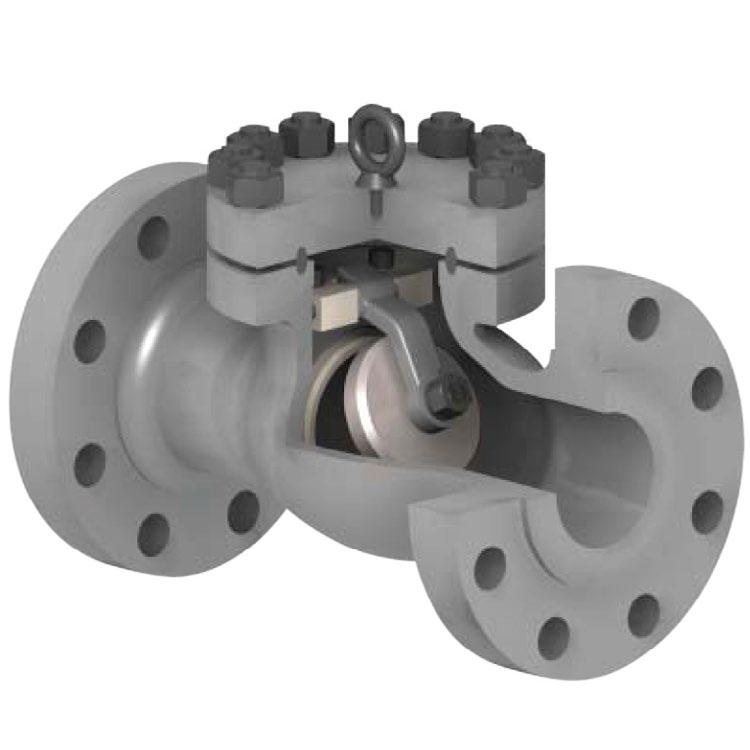
Description Material
Body ASTM A216 WCB
Disc ASTM A216 WCB+13CR
Nut ASTM A194 2H
Split Pin AISI 304
Washer AISI 304
Disc Arm ASTM A216 WCB
Seat ASTM A105+CR13
Shaft ASTM A276 410
Key AISI 1045
Gasket SS316+Graphite
Bonnet ASTM A216 WCB
Bolt ASTM A193 B7
Nut ASTM A194 B8
Lifting Eye Steel
Washer SS420
Packing Flexible Graphite
Gland Flange ASTM A105
Bolt ASTM A193 B7
Lever AISI 1025
Washer SS410
Nut ASTM A194 2H
Locking Device Bolt AISI 1020
Lock Plate AISI 1020
• Locking Lever
• Low head loss & minimum pressure loss can be achieved.
• Counterweight - Dashpot
• Hydraulic Dampened
L.
L.
H.
Description Material Specs.
Body Carbon Steel A216 Gr. WCB
Cover Carbon Steel A216 Gr. WCB
Disc / Facing Stainless Steel A216 Gr. WCB+410SS/CR13/Stellite
Hinge Carbon Steel A216 Gr WCB
Hinge Pin Stainless Steel A182 Gr. F6a/CR13
Seat / Facing Stainless Steel A182 Gr. F6a/A105 + Stellite
Plug Carbon Steel A108 Gr.1045
Cover Bolt Alloy Steel A193 Gr. B7/B7M
Cover Nut Alloy Steel A194 Gr. 2H/2HM
Disc Nut Carbon Steel A563 Gr. B
Washer Stainless Steel A276 Type 304
Eye Bolt Carbon Steel A307 Gr. B
Name Plate Stainless Steel 304/AL
Gasket Soft Metal Ring CAD Plated / + Graphite
Standards
Face to Face/End to End ASME B16.10
Flange Dimensions ASME B16.5
Basic Design ASME B16.34/API 594*/API 6D** & MSS-SP144
Testing API 598
*Full API 594 compliance where stated. **API 6D also available, refer to drawing.
DIMENSIONS (MM)
A216 Gr. WCB
A216 Gr. WCB
Disc / Facing
A216 Gr. WCB+410SS/CR13/Stellite Hinge
A216 Gr WCB
A182 Gr. F6a/CR13 Seat / Facing
Plug
A182 Gr. F6a/A105 + Stellite
Steel A108 Gr.1045
Cover Bolt Alloy Steel A193 Gr. B7/B7M
Cover Nut Alloy Steel A194 Gr. 2H/2HM
Disc Nut Carbon Steel A563 Gr. B
Washer Stainless Steel A276 Type 304
Eye Bolt Carbon Steel A307 Gr. B
Name Plate Stainless Steel 304/AL
Gasket Soft Metal Ring CAD Plated / + Graphite
*Full API 594 compliance where stated. **API 6D also available, refer to drawing.
compliance where stated.
also available, refer to drawing.
Description Material Specs.
Body Carbon Steel A216 Gr. WCB
Cover Carbon Steel A216 Gr. WCB
Disc Facing Stainless Steel A182 Gr. F6a/CR13 or Stellite/HF
Hinge Pin Stainless Steel A182 Gr. F6a/CR13
Seat Ring Stainless Steel A182 Gr. F6a/CR13, Stellite/HF Plug Carbon Steel A108 Gr.1045
Cover Bolt Alloy Steel A193 Gr. B7/B7M
Cover Nut Alloy Steel A194 Gr. 2H/2HM
Retainer Stainless Steel A240 304
Washer Stainless Steel A276 Type 304
Eye Bolt Carbon Steel A307 Gr. B
Name Plate Stainless Steel 304/AL
Bonnet Clamp Steel A29 1045
Gasket Spacer Stainless Steel A240 304
Gasket Graphite/SS/Soft Metal Graphite/316SS/Plated Iron
A2
Description
Cover
Disc Facing
Hinge Pin
Seat Ring
Plug
A216 Gr. WCB
A216 Gr. WCB
A182 Gr. F6a/CR13 or Stellite/HF
A182 Gr. F6a/CR13
Steel A182 Gr. F6a/CR13, Stellite/HF
Steel A108 Gr.1045
Cover Bolt Alloy Steel A193 Gr. B7/B7M
Cover Nut Alloy Steel A194 Gr. 2H/2HM
Retainer Stainless Steel A240 304
Washer Stainless Steel A276 Type 304
Eye Bolt Carbon Steel A307 Gr. B
Name Plate Stainless Steel 304/AL
Bonnet Clamp Steel A29 1045
Gasket Spacer Stainless Steel A240 304
Gasket Graphite/SS/Soft Metal Graphite/316SS/Plated Iron
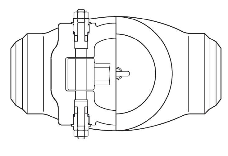
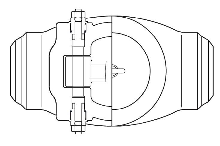
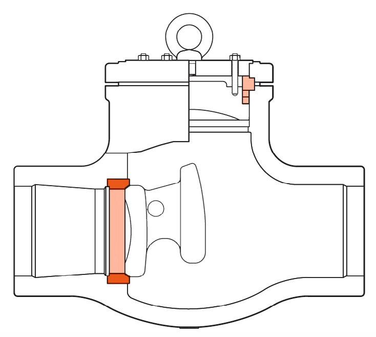
Non return Piston Check valve, lift type, bolted bonnet, guided disc. Flange drilling ANSI 150 to 600 and AS 2129 table D to H and AS 4087/EN/ISO PN10 to 100. Guide pin and cage and/or bonnet guide cage as required (refer to drawings) For horizontal installations in applications such as industrial, mining and mechanical services. Suitable for super-heated steam, H.T.H.W., steam, condensate and water. Guiding of stem assures smooth operation.
Other body materials like Bronze and WC6 also available.
AP300XU 150 CLASS
280 PSI CWP (WOG)
170 PSI Saturated Steam (at 260°C)
AP301XU 300 CLASS
720 PSI CWP (WOG)
600 PSI Saturated Steam (at 260°C) For superheated steam consult pressure/temp chart
AP302XU 600 CLASS
1440 PSI CWP (WOG)
1100 PSI at 260°C, 825 psi at 400°C. Consult chart for other temperatures WC6 body is available for high temperature applications
6
7
5
2
Basic Design ASME B16.34/BS 1873 or API 6D
Face to Face Dimension ASME B16.10
End to End Dimension ASME B16.10
Flanged Ends ASME 16.5
B.W. Ends ASME B16.25
Drilling to ANSI or BS/AS 2129 Table D to H and PN10 to 100
CLASS 150
(Table D to F) (PN10 21)
CLASS 300
(Table F to H) (PN25 50)
Cage
A182 Gr. F6a/CR13 or Stellite/HF
A182 Gr. F6a/CR13, Stellite/HF
A194 Gr. 2H/2HM Disc
A563 Gr. B
A276 Type 304 Eye
Carbon Steel A307 Gr. B
Gasket Ring/ Spiral CAD Plated Ring / Spiral Wound FULL PORT
Cage
Body
Bonnet
Disc
Steel A351 Gr. CF8/CF8M
A351 Gr. CF8/CF8M
Stem Stainless Steel A182 Gr. F304/F316
Hand Wheel Malleable Iron A197
Yoke
Gland Flange
Gland
Wheel
Bonnet Bolt Stainless Steel A193 Gr. B8
Bonnet Nut Stainless Steel A194 Gr. 8
Gland Bolt Stainless Steel A193 Gr. B8
Gland Nut Stainless Steel A194 Gr. 8
Gland Bolt Pin Stainless Steel A182 Gr. F304
Bearing Stainless Steel Thrust Ball
Grease Nipple Bronze B62 Cr. Plating
Set Screw Stainless Steel A193 Gr. B8
Name Plate Stainless Steel A240 Type 304
Packing Asbestos Free PTFE/Graphite
Bonnet Gasket PTFE or Graphite Sheet or SS + SW Graphite/PTFE
Seat Stainless Steel (Integral) A351 Gr. CF8/CF8M or ST #6
Back Seat Stainless Steel (Integral) A351 Gr. CF8/CF8M
Investment cast to 300NB (12”)
Self aligning gland flange
Larger sizes fitted with thrust bearings for ease of operation Yoke sleeve made from AL-Bronze or Austenitic DI for corrosion & wear resistance.
Description Material Specs.
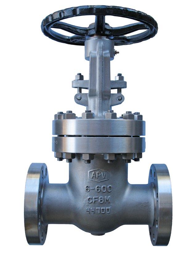
Body Stainless Steel A351 Gr. CF8/CF8M
Bonnet Stainless Steel A351 Gr. CF8/CF8M
Disc Stainless Steel A351 Gr. CF8/CF8M
Stem Stainless Steel A182 Gr. F304/F316
Hand Wheel Malleable Iron A197
Yoke Sleeve Austenitic DI A439 Gr. D2C or NR Bronze
Gland Flange Stainless Steel A351 Gr. CF8/CF8M
Gland Ring Stainless Steel A182 Gr. F304/F316
Wheel Nut Stainless Steel A351 Gr. CF8/CF8M
Bonnet Bolt Stainless Steel A193 Gr. B8
Bonnet Nut Stainless Steel A194 Gr. 8
Gland Bolt Stainless Steel A193 Gr. B8
Gland Nut Stainless Steel A194 Gr. 8
Gland Bolt Pin Stainless Steel A182 Gr. F304
Bearing - Thrust Ball
Grease Nipple Bronze B62 Cr. Plating
Set Screw Stainless Steel A193 Gr. B8
Name Plate Stainless Steel A240 Type 304
Packing Asbestos Free PTFE/Graphite
Bonnet Gasket PTFE or Graphite Sheet or SS + SW Graphite/PTFE
Seat Stainless Steel (Integral) A351 Gr. CF8/CF8M or ST #6
Back Seat Stainless Steel (Integral) A351 Gr. CF8/CF8M
Investment cast to 300NB (12”)
Self aligning gland flange
Larger sizes fitted with thrust bearings for ease of operation
Yoke sleeve made from AL-Bronze or Austenitic DI for corrosion & wear resistance.
A.
A.
*Weights are for API 603. For API 600 weights see Page 24. For Buttweld weights and RTJ dimensions see overview brochure.
Hand Wheel
Gland Flange
Gland Ring
Disc Gland
Yoke Bush Austenitic DI
Bonnet Bolt
Bonnet
Standards
*API 623 where specified
Investment cast to 300NB (12”)
Self aligning gland flange
Larger sizes fitted with thrust bearings for ease of operation
Yoke sleeve made from AL-Bronze or Austenitic DI for corrosion & wear resistance. Description

Body Guided Disc
Body guided disc style eliminates side thrust and provides longer disc, seat and body life as well as ensuring positve shut-off and low closing torque.
C.
*Weights are for ANSI B16.34. For API 600 weights see Page 34-35. For 14” to 16” dimensions see overview brochure. For Buttweld weights and RTJ dimensions see overview brochure.
Parts Name Materials
Body
Bonnet
Disc
Arm
Hinge Pin
ASTM A351 Gr. CF8/CF8M
ASTM A351 Gr. CF8/CF8M
ASTM A351 Gr. CF8/CF8M
ASTM A276 Gr. CF8/CF8M
ASTM A276 Gr. 304/316
Split Pin AISI 304/316
Disc Nut AISI 304/316
Disc Washer AISI 304/316
Bonnet Bolt / Nut
Gasket
Plug
ASTM A193 Gr. B7/A194 Gr. 8/B8M
Teflon or Graphite or 316/GRP SPW
ASTM A276 Gr. 304/316
Plug Gasket Teflon
Eye Bolt*
Seat (Integral)
* Larger sizes only
ASTM A193 B8
ASTM A351 Gr. CF8/CF8M or ST #6
598
*Where specified
(12”)
CRYOGENIC VALVES - STAINLESS STEEL
CRYOGENIC VALVES
General Design & Wall Thickness
Cast Gate Valves - ASME B16.34
Cast Globe Valves - ASME B16.34
Inspection & Test BS 6364
Long Life Seating Surface
Stellite 6 faced both seat and wedge/disc to prevent seizing and galling.
End Flange Dimensions
ASME B16.5
Butt Weld End Dimensions
ASME B16.25
End to End Dimensions
Flanged - ASME B16.10
Butt Weld - ASME B16.10
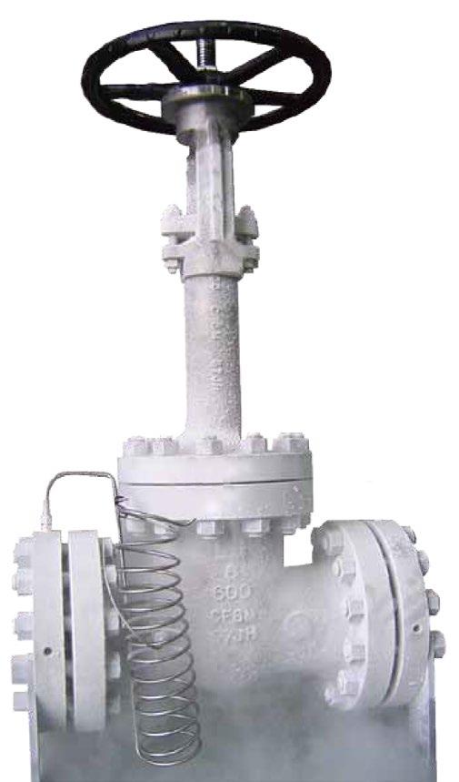
Extended Bonnet Bolted or integral vapour space extended bonnet of sufficient length to keep stem packing out of the cold zone and free of ice formation.
Austenitic Stainless Steel Forgings or Castings Tough at cryogenic temperatures and can be classed as a ‘cryogenic steel’ with good impact strength and corrosion resistance.
Shell and Trim Parts are all austenitic stainless steel and sub-zero treated in LN.
Insulation Collar / Drip Plate A ‘welded’ insulation collar/drip plate or a ‘clamped on’ insulation collar/drip plate can be provided on request.
Body
Yoke Integrated bracket, high rigidity, more assembly space
Heat treated and charpies impact test at 196°C. Investment cast, API 600 wall thickness.
Flexible wedge. Pressure relief hole in the inlet direction. Mirror lapped seat & disc faces. Stellite 6 seat facing.
More gasification space to avoid freezing and prevent stem packing leakage. Optional baffle.
Hardened and heat treated
As per clients requirements.
Manufacturing Standards
Design Standard
Face to Face ASME B16.10
Welded End Connection ASME B16.5
Flanged end connection ASME B16.5
Inspection
622 & ISO 15848-1
Fugitive Emission Certified
Extended Bonnet Integral bonnet with more gasification space to avoid freezing and prevent packing leakage.
Body Heat treated and charpies impact tested at 196°C. Investment cast ANSI B16/API 600 wall thickness.
Body Guided Disc style eliminates side thrust and provides longer disc, seat and body life as well as ensuring positve shut-off and low closing torque.
Hardened & heat treated
50~600AP143XXXXXXXXXX-XC
Manufacturing Standards
Design Standard API 600, BS 6364
Face to Face ASME B16.10
Welded End Connection ASME B16.5
Flanged end connection ASME B16.5
Inspection and Test API 598, BS 6364
Lifting Lug For lifting transportation.
Body Investment cast, API 6D/ANSI B16/API 600 heavy wall. Heat treated and charpies impact tested at 196°C.
Hinge Pin
Heat treated, hardened steel.
API 6FD & API 6FA-5th Firesafe Certified (API 6D Version)
50~600AP159XXXXXXXXXX-XC -
50~400AP175XXXXXXXXXX-XC - CLASS 600
50~400AP187XXXXXXXXXX-XC - CLASS 900
Manufacturing Standards
Design Standard API 600, BS 6364, API 6FD, API 594
Face to Face ASME B16.10
Welded End Connection ASME B16.5
Flanged end connection ASME B16.5
Inspection and Test API 598, BS 6364
50~350AP199XXXXXXXXXX-XC - CLASS 1500
* As per clients requirements.
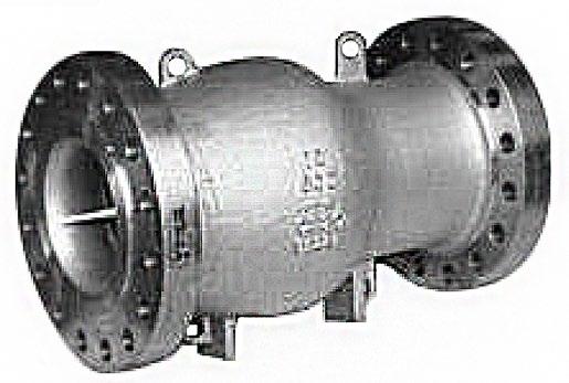
• Design to API 6D and Face to Face Distance as per manufacturer’s standards.
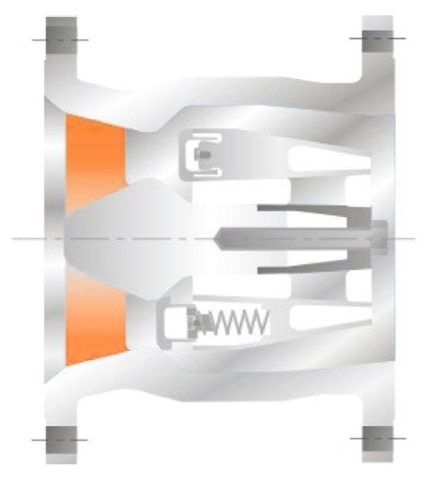
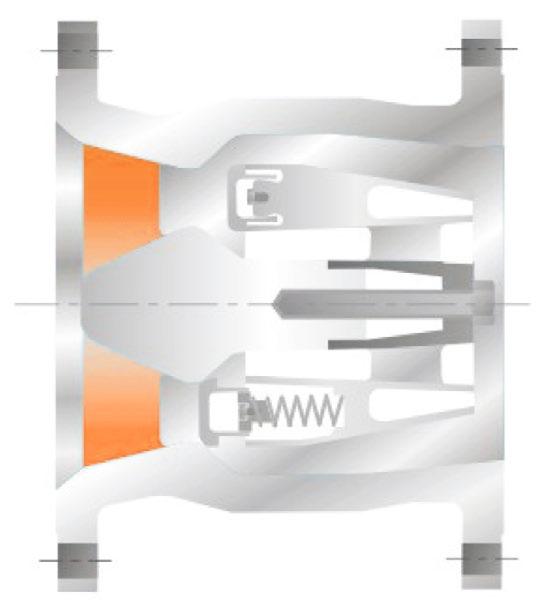
• Fast acting spring prevents water hammer and pressure surge, this is a truly Non Slam Check Valve.
• Short Travel and Ultra Light weight Disc make the advantages of Non Slam Check Valves possible and reduces water hammering. Quick closing and fast travelling disc are the fundamental design features.
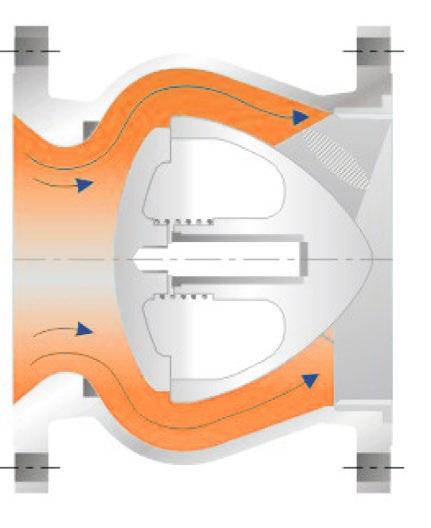
• High Velocity and Gas Flow under compressed conditions can reach sonic velocity and the ‘sonic booms’ are detrimental to the valves operation. The simple but precisely calculated spring design overcomes this problem.
• Bernoulli’s equation of conservation of energy is the solution for spring design. Velocity head exchanges the energy with Pressure Head and the Supercheck Non Slam Check keeps on performing without the fear of sonic boom and valves offer low Pressure Drop when compared to Dual Plate Check Valves static pressure. Dropping the velocity head at vena contracta increases static pressure reducing cavitation.
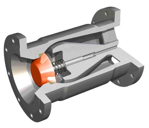
• Single piece body construction allows High Pressure Applications and Non Slam Nozzle Check Valves are inherently Fire Safe.
• Rating ANSI Class 150, 300, 600, 900, 1500 & 2500 & up to 10,000 psi.
• Material ASTM A105, A182, Gr. LF2, Gr. F316, Gr. F51, Gr. F55 etc.
• Designed using Computational Fluid Dynamics (CFD)
• Low head loss & minimum pressure loss can be achieved.
• Metal to Metal seated design.
• Conical seating surface is self aligning & provides tight shut off.
• Spring loaded disc design allows mounting in any orientation.
APPLICATIONS
• Chemical, Oil & Gas Industries
• Residual Heat Removal Systems
• Nuclear Power Plants
• Offshore & Onshore Production Platform, FPSO
• Containment Isolation
• Water, Steam, Gas, Vacuum
• Steam Injection Systems
• Power Station, Water Pumping Stations
• Natural Gas, Refineries
• Critical Equipment Discharge
• Gas Compressor Unit
• Cracker Plants
• Non Slam Closure
• Extremely quick Closure
• Low Pressure Loss
• Short stroke of disc
• Axial movement of disc
• Disc’s minimal wear characteristics
Face To Face
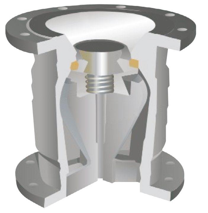
Single Spring Loaded Nozzle Check Valve SW-NCA Series
Up to 250NB (10”) and 150~300LBS single spring loaded design (Model Number - SW-NCA) minimum pressure loss with excellent dynamic performance.
Face To Face
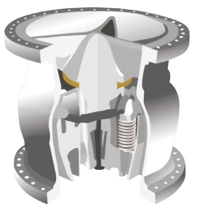
Multi Spring Loaded Nozzle Check Valve SW-NCB Series
250NB (10”) and above 150~2500LBS multi spring loaded design (Model Number - SW-NCB) minimum pressure loss with excellent dynamic performance.
Example Only. Refer to as built drawings. (FL-NCFO Series) also refer to drawings as all dimensions are different.
Dimension for larger valve sizes available upon request. Also available with JIS, DIN, BN, AS and ISO dimensions. API 2000, 3000, 5000, 10000 also available
Supercheck Nozzle Check valve is designed to meet the criteria of conventional check valves by allowing forward flow under normal conditions, opening easily and firmly backseating at low velocity.

ANSI 300
SW-NCA Single Spring
SW-NCB Multi Spring
Example Only. Refer to as built drawings. (FL-NCFO Series) also refer to drawings as all dimensions are different.
Dimension for larger valve sizes available upon request. Also available with JIS, DIN, BN, AS and ISO dimensions. API 2000, 3000, 5000, 10000 also available
Supercheck Nozzle Check valve is designed to be closed prior to reverse flow as non-slamming with a spring loaded disc that allows mounting in any orientation.
ANSI 600
ANSI 900
SW-NCA Single Spring
SW-NCB Multi Spring
Pattern
Example Only. Refer to as built drawings. (FL-NCFO Series) also refer to drawings as all dimensions are different.
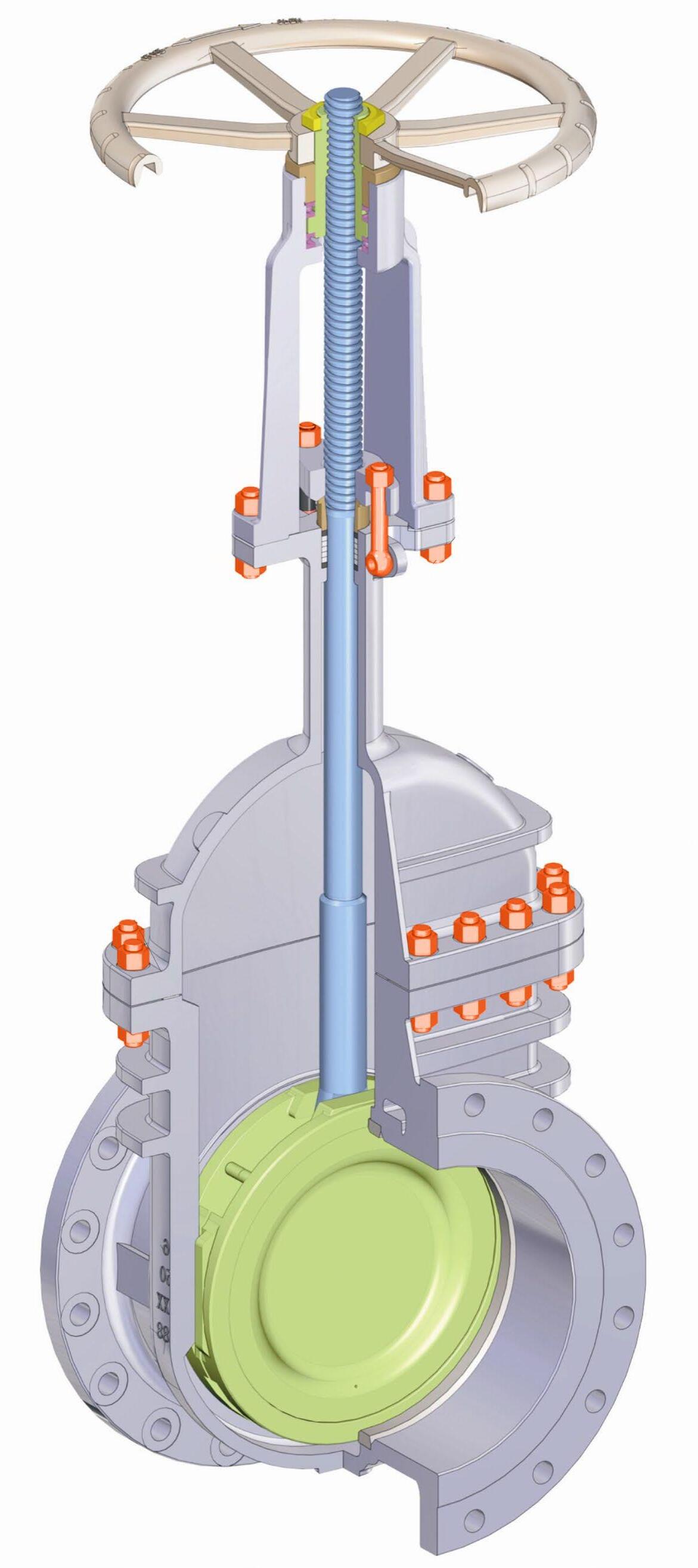
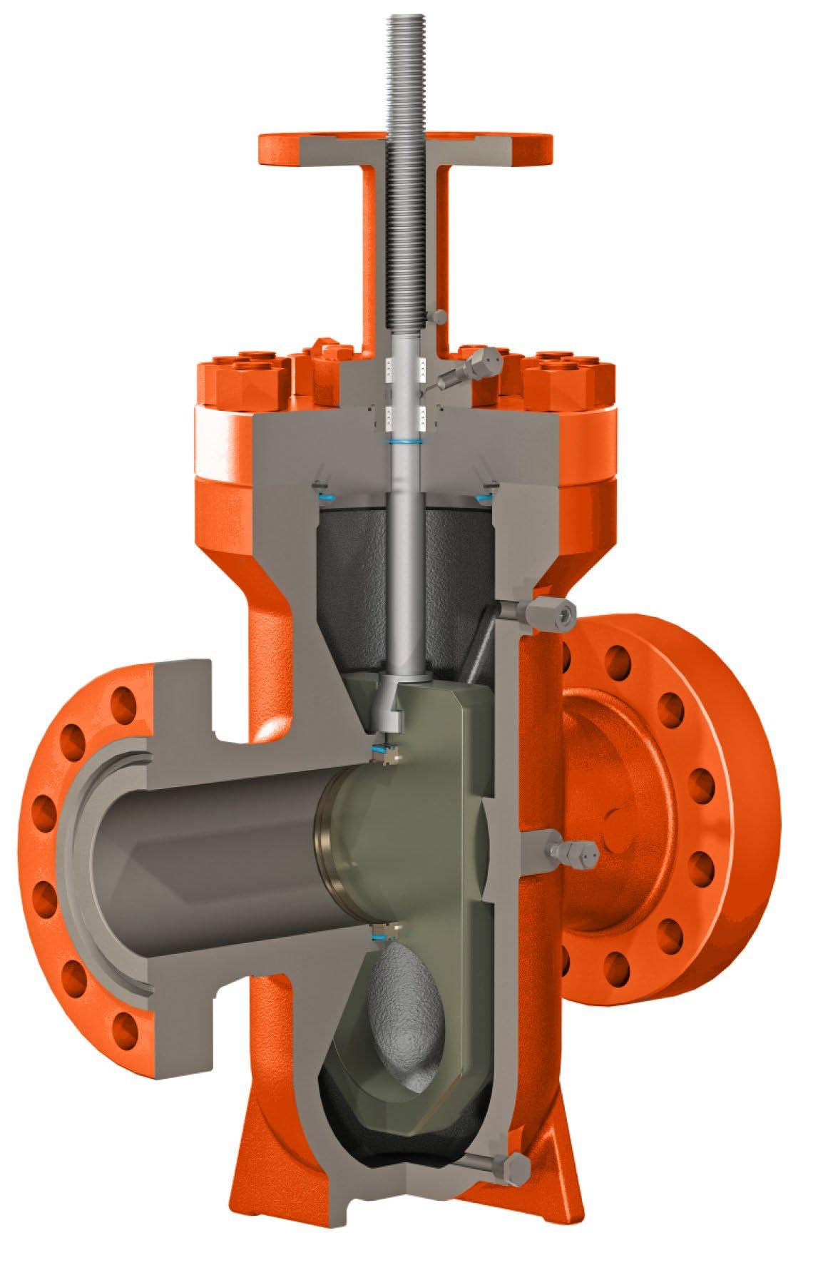
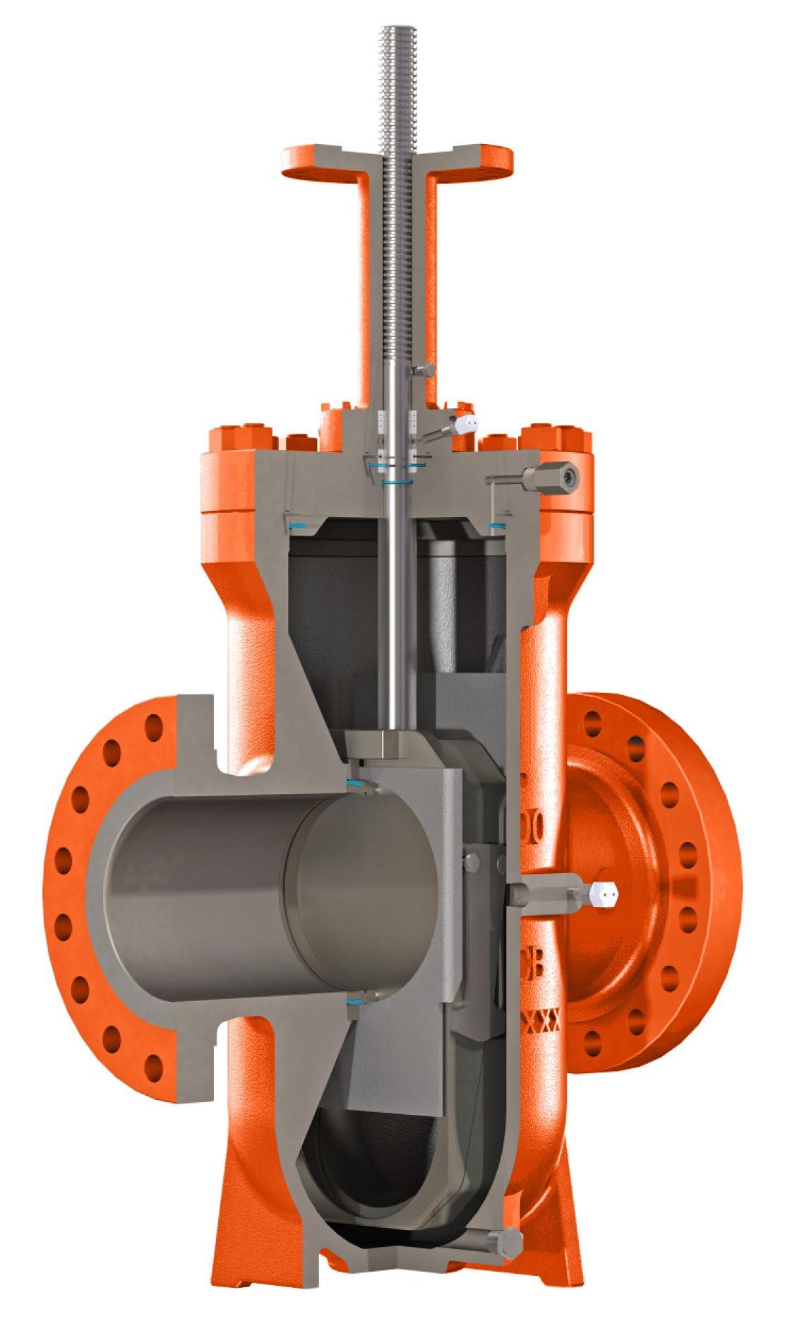
Through conduit Full bore
The through conduit opening design provides full flow passage and allows for the smooth passing of pipeline pigs. Pressure drop through the valve is no greater than that through an equal length of equal diameter pipe.
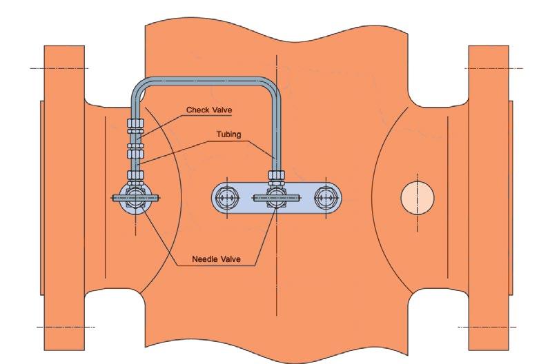
External pressure relief system for cavity over pressure protection
Due to the double tight sealing isolation design for expanding gate valve, cavity pressure can increase significantly through thermal expansion of fluid in the cavity. A body cavity thermal relief system can be provided to relieve this excess body cavity pressure.
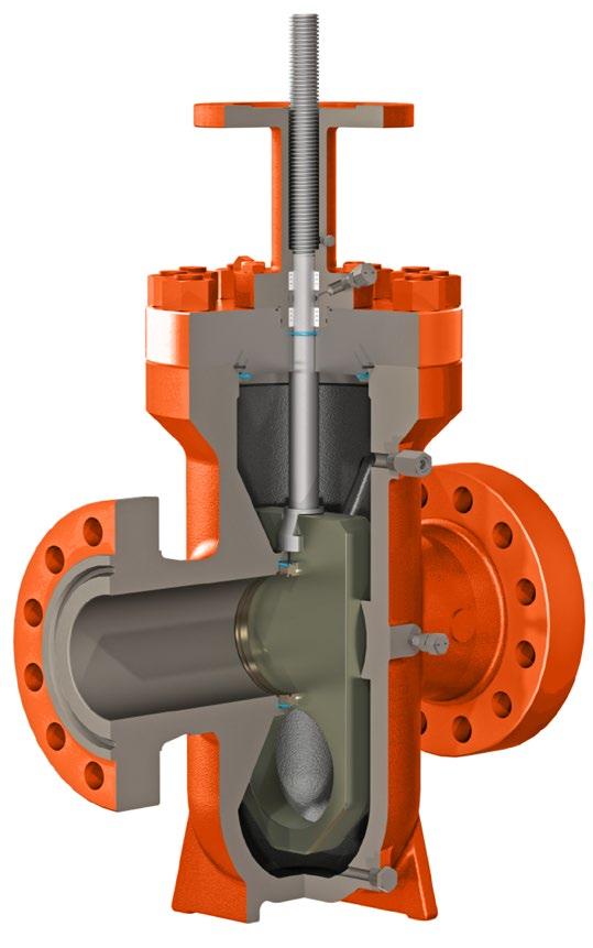
In Line repairable
The top entry design allows for access to all internal parts if maintenance is required with the valve still in the pipeline.
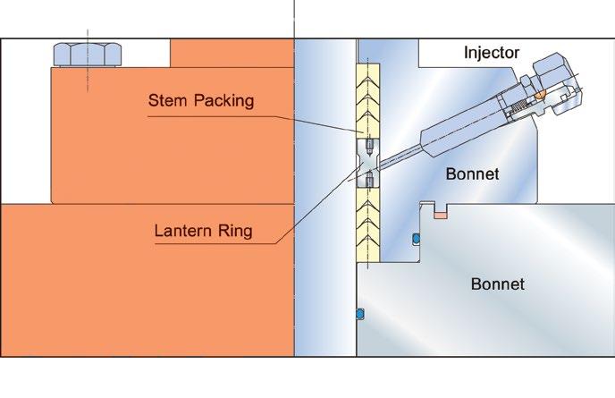
Ease of on-line stem packing maintenance
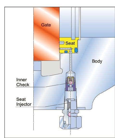
Top and bottom Chevron PTFE packing + lantern ring is the standard stem seal equipped with a stem injector with integrated check valve. Injectable packing material can be injected directly into the packing box through the injector to enhance stem sealing while the valve is under pressure.
Emergency sealant injection on seats
Provision of seat injectors with integrated check valve provides emergency backup sealing. Additionally, an inner check valve is installed in front of the seat injector to prevent blow out in case of wrong operation. If a seal surface is damaged by foreign matter, valve leakage can be eliminated by using a sealant injected into a specially designed groove in the seat ring assembly. This secondary seat sealant injection backup provides a peace of mind to users who demand reliable block valve service until the valve can be properly serviced. Seats may be lubricated by injecting lubricant to enhance service life and reduce operating torque.
Double block and bleed (DBB)
Double sealing established by initial plastic-to-metal contact in addition to metal-to-metal contact, both upstream, downstream. In the closed position, both upstream and downstream pressures energize the seats to form a tight seal on both seats simultaneously. This allows the body cavity to be manually bled.
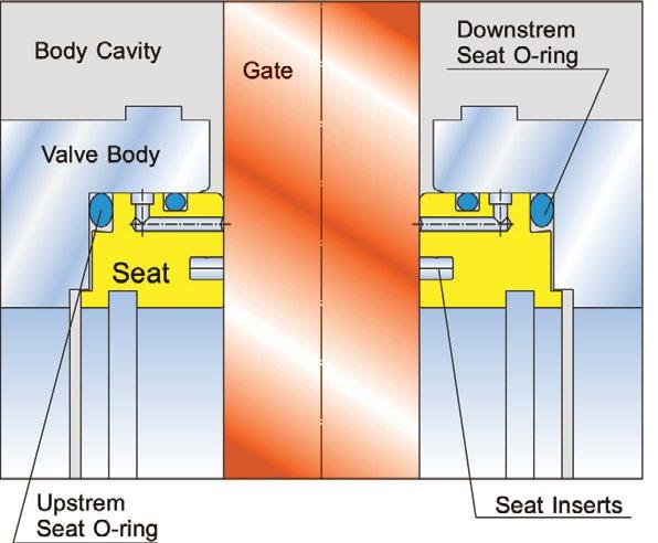
Pressure energised seats
As the upstream pressure increases, the upstream seat is pushed against the slab gate (piston effect), and subsequently the slab gate pushes against the downstream seat, creating a tight seal between both seats and the slab gate. In the absence of line pressure, the energized O-rings behind the seats provide the seating force on the slab gate to maintain a tight effective seal.
A soft seat insert in each seat is protected by the metal sealing surfaces in full contact with the gate, in both open and closed positions, completely isolated from the flow stream, greatly extending the seat life.
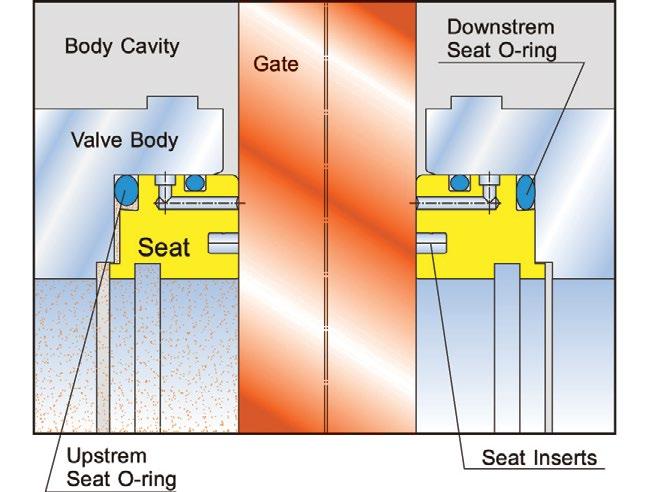
Cavity over pressure self-relieving
When the medium trapped in the body cavity expands as a result of the thermal expansion, the pressure buildup will push the upstream seat back into its recess and relieves to the upstream through the gap between the seat and the slab gate.
Protection of seat faces
Seat faces are not exposed to the flow stream and in full contact with the gate, in both open and close position, greatly extending seat life.
When the valve in the closed position with equal pressure in the valve, the energized seat O-Ring on both seats will push the seat rings against the gate to provide an initial soft-to-metal sealing.
When the line pressure is applied to the valve, the gate will be pushed against the downstream seat until the gate compresses the soft seat insert and forms soft-to-metal and metal-to-metal double seal. The downstream O-ring provides the seal between the downstream seat and body. The force of line pressure acting on the upstream seat against the gate provides a soft-to-metal seal, and the upstream seat O-ring provides the seal between the upstream seat and body.
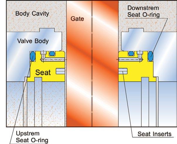
When the valve cavity pressure exceeds line pressure due to thermal expansion, the upstream seat is forced back into its recess and the excess pressure in the body cavity is relieved between the seat and the gate into the line.
Saf-T-Seal®* style
Through conduit design with minimum flow resistance
Double sealing replaceable seat
Locking device
Backseated Stem
Body thermal relief system upon request
Stem extension upon request
Double block and bleed upon request
Soft seat or ‘Metal to Metal’

SPECIFICATIONS
Basic Design API 6D ASME B16.34
Face to Face API 6D
End Flange 2”-24” ASME B16.5
26”- 40” ASME B16.47
B.W End ASME B16.25
Test and Inspection API 6D & API 598
Manufacturing to NACE MR0175 on request


OVERVIEW EXPANDING GATE VALVE
Double isolation and bleed DIB-1 (both seats bi-directional)
Double sealing established on each seat bi-directionally by initial plastic-to metal contact in addition to metal-to-metal contact, both upstream, downstream and body cavity. In the closed position, the gate forms a tight seal simultaneously on both seats bi-directionally. This allows the body cavity to be manually bled. An automatic cavity pressure relief device is provided to relieve the build-up of over pressure in the body cavity.
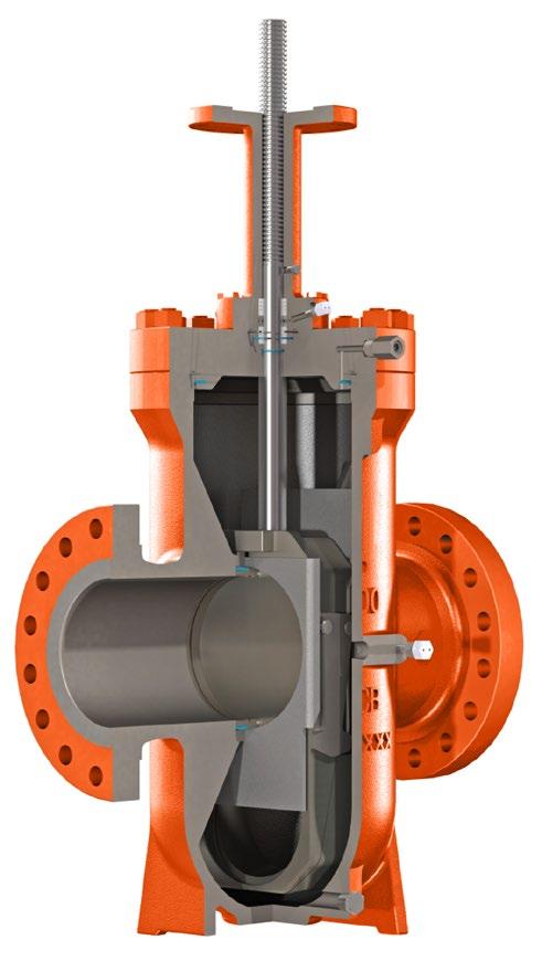
Mechanically induced bubble tight seal
When closing, the segment is positioned by a mechanical stop while the gate continues going downward, expanding the segment and gate against their opposite seats. This action forms a bubble tight seal on both the upstream and downstream seat to reach a double isolation sealing function.
Wear and tear reduction
When the valve is completely closed, the gate and segment are wedged tightly against each seat. During operation, the gate and segment retract from the seats prior to stroking; this retraction provides an operating clearance to reduce rubbing of the resilient seat material and protects the sealing surfaces. Additionally this reduces the operating torque and allows a smaller and more economical operator for smooth operation.
In the fully closed position, the segment is positioned by the mechanical stop and the gate is wedged downward under stem thrust force, expanding the segment and gate to form a tight seal on each seat bi-directionally between upstream and downstream.
During travel between fully open or close position, the gate and segment retract from the seats prior to travel; this retraction provides an operating clearance to reduce wear on the sealing surface and operating torque.
Lever lock mechanism - Size 150NB (6”) and above
The lever arm maintains the gate & segment surfaces parallel by guide plates, while the expanding gate assembly is moving through its stroke. Near the end of stroke, the guide plate allows the lever arm to tilt. The gate and segment slide against their angled faces under stem provided thrust force, creating the expanding seal action. In their final position, the gate and segment are mechanically secured in place. The guide plates forms a rail at both sides of the expanding gate assembly to guide its movements and align it with the seats.
When the bore of the segment is aligned with the body bore, the segment is positioned by the mechanical stop and the gate continues to move upwards, expanding the gate and the segment to form a through conduit bore and protect the sealing surface from flow erosion.
Pow-R-Seal
Through conduit design with
Double-sealing replaceable seat
Locking device
Body thermal relief system
Stem extension upon request
Soft Seat or ‘Metal to Metal’
SPECIFICATIONS
Basic Design API 6D ASME B16.34
Face to Face API 6D
End Flange 2”-24” ASME B16.5
B.W. End ASME B16.25
Test and Inspection API 6D & API 598
Manufacturing to NACE MR0175 on request
Wafer End Connection
Automatic Relief of Excess Body pressure
Total Seal Upstream and Downstream
Floating Seats with PTFE inserts
Solid parallel Faced Gate or through conduit API 6D Gate
Outside Screw & Yoke Bolted Bonnet
Available with Gear Operator and Automatic Special features according to Customers requirements.
Basic Design ANSI B16.10 ANSI B16.34 API 6D
Flanges up to 600NB (24”) ANSI B16.5 from 650NB (26”) ANSI B16.47 MSS SP44 API 605
Face to Face ANSI B16.10
Testing API 598, API 6D
The flow characteristics of the full conduit version is equal to that of a pipeline with a matching bore. For solid parallel slab the cavity is slightly smaller than that of a wedge gate.
FEATURES
Pressure seal bonnet
Complete flow isolation in either direction
Minimum pressure drop
Inherent self cleaning action
Freedom from leakage, resistant to temperature or pressure changes
In line maintenance
By pass available upon request
SPECIFICATIONS
Basic Design API 600, ASME B16.34 & MSS SP-144
Face to Face ASME B16.10
End Flange ASME B16.5
B.W End ASME B16.25
Test and Inspection API 598 AP76S-P 600LB
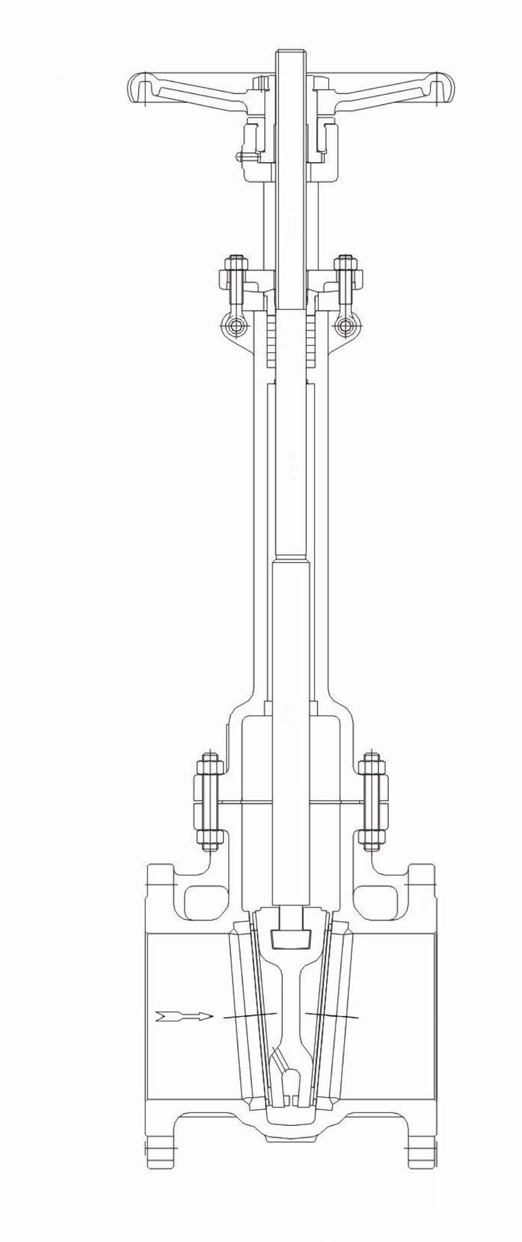
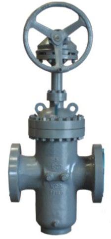
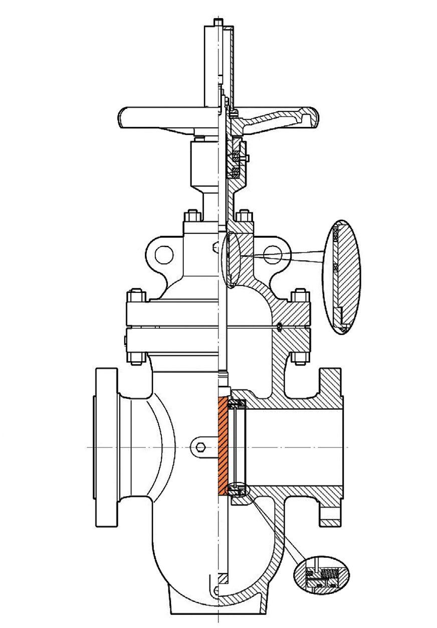
For installation in applications such as industrial, mining and mechanical services. Suitable for super-heated steam, H.T.H.W steam condensate and water. This design consists of two discs, kept in contact with parallel body seats, using the line pressure and seating action to effect tight closure.
Temperature changes in the line are accommodated by the expanding disc and do not affect the action of the valve. When being opened or closed, the discs slide across the seat faces, dislodging any foreign matter. The valve operating stem is outside screw rising through the handwheel.
These valves are suitable for full bore steam use, where a low pressure drop across the valve is required. Also suitable for water, oil, gas, etc.
(Table D to F)
For superheated steam etc. consult chart. WC6 chrome-moly available body for high temperature applications. STANDARD
SPECIFICATIONS
Basic Design API 600, ANSI B16.34
Face to Face Dimension ANSI B16.10
End to End Dimension ANSI B16.10
Flanged Ends - ANSI 16.5
B.W. Ends ANSI B16.25
Drilling to ANSI or BS/AS 2129 Table D to H or AS 4087 / AS 4331 / ISO 7005-1 PN 10 to 250
Pressure/Temperature ratings to ANSI B16.5
Disc* A105+410
Spring* Inconel X-750
Washer 304 SS
Screw B8
Stem ASTM A182 F6A/17-4PH
Gasket 304 S.W. +Graphite
ASTM A193 Gr. B7
ASTM A194 Gr. 2H
Bonnet ASTM A216 Gr. WCB
Back Seat Ring ASTM A182 Gr. F6
Packing Spacer ASTM A182 Gr. F6
Packing Flexible Graphite
Grease Nipple 304 SS
* Also available with expanding wedge energiser (no spring) style - refer to drawing.
O.S. & Y. Rising Stem Full Port, Expanded Parallel Slide Gate Valve, Double Disc, Pressure Seal or Bolted Bonnet, Welded-in or Threaded Seat Rings. Mechanically loaded seating for low and high pressure sealing.
Parallel slide dual loaded discs ensure superior shut off and allow by-pass/bleed fitment (double block and bleed requires soft seat inserts).
Pressure/temperature charts available on request.
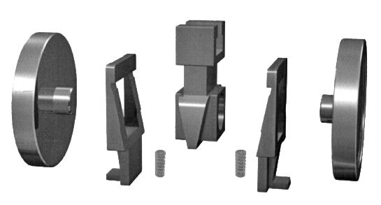
PRESSURE/TEMPERATURE
300
For superheated steam etc. consult chart. WC6 chrome-moly available body for high temperature applications.
Suitable for super-heated steam, H.T.H.W steam condensate and water.
Temperature changes in the line are accommodated by the expanding disc and do not affect the action of the valve. When being opened or closed, the discs slide across the seat faces, dislodging any foreign matter.
These valves are suitable for full bore steam use, where a low pressure drop across the valve is required. Also suitable for water, oil, gas, etc.
O.S. & Y. Rising Stem Full Port, Expanded Parallel Slide Gate Valve, Double Disc, Pressure Seal or Bolted Bonnet, Welded-in or Threaded Seat Rings. Mechanically loaded seating for low and high pressure sealing.
Parallel slide dual loaded discs ensure superior shut off and allow by-pass/bleed fitment (double block and bleed requires soft seat inserts).
Pressure/temperature charts available on request.
Part Material
1 Body ASTM A217 WCB
2 Seat Ring ASTM A105+STL.6
3 Wedge Blocks ASTM A743 CA40
4 Discs ASTM A105+STL.12
5 Springs Inconel X-750
6 Disc Yoke ASTM A743 C40
7 Guides C.S.
* Also available with expanding wedge energiser (no spring) style - refer to drawing. Buttweld ends
8 Stem ASTM A182 F6A/17-4PH
9 Studs ASTM A193 B7
10 Nuts ASTM A194 2H
11 Gasket 304SS+GRAPHITE
12 Bonnet ASTM A216 WCB
13 Back Seat ASTM A276 410
14 Packing FLEXIBLE GRAPHITE
15 Packing 316+BRAIDED GRAPHITE
16 Gland ASTM A276 410
17 Gland Flange ASTM A217 WCB
18 Pins AISI 1035
19 Eyebolts ASTM A193 B7
20 Nuts ASTM A194 2H
21 Stem Nut ALUMINIUM BRONZE
22 Retaining Nut AISI 1035
23 Handwheel MALLEABLE IRON
24 Nuts AISI 1035
Yoke ASTM A216 WCB
Studs ASTM A193 B7
Nuts ASTM A194 2H
Grease Nipple BRASS
CAT 50~600AP47KSXXXX~50~600AP87KSXXXX CLASS 150-1500
EXPANDING PARALLEL SLIDE
SPECIFICATIONS
Basic Design API 600, ANSI B16.34
Face to Face Dimension ANSI B16.10
End to End Dimension ANSI B16.10
Flanged Ends ANSI 16.5
B.W. Ends ANSI B16.25
Drilling to ANSI or BS/AS 2129 Table D to H or AS 4087 / AS 4331.1 / ISO 7005-1 PN 10 to 250
Pressure/Temperature ratings to ANSI B16.5
* Add XU modifier to end of model suffix if stellite seat, if stellite seat & disc add U modifier to end.
OVERALL DIMENSIONS (MM) & WEIGHT (KG)
Note: 15mm to 40mm NB 150 ~ 2500 Class also available refer to individual drawings. PARALLEL SLIDE GATE VALVES - CAST STEEL PARALLEL SLIDE GATE VALVE
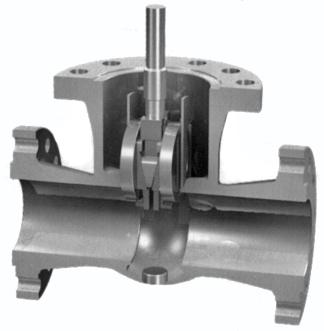
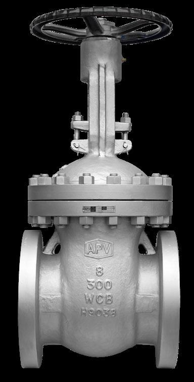
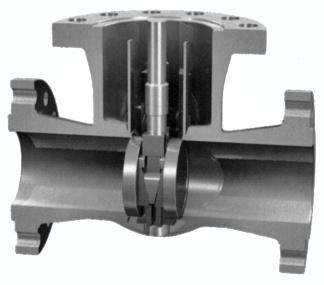
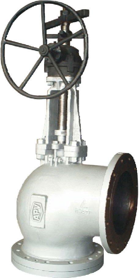
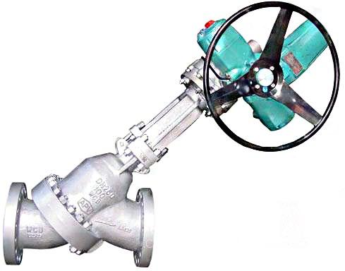
Our APV slurry valves have an advanced design providing optimum sealing and flow channel design. These valves have been widely used in many big aluminium oxide enterprises.
B16.34
B16.5
Seat, Valve Disc
Sealing surface YG Hard alloy, tungsten carbide, YG
The APV slurry valve features a valve body split from top and bottom. The two bodies are connected by bolts and installed with the valve seat between them, for ease of replacing the valve seat. High hardness metal protection ring with anti-corrosive performance is ensured according to the working conditions, providing effective protection for the trims. The internal cavity of the valve body is designed to provide a streamlined channel with wear resistant performance and low flow resistance.
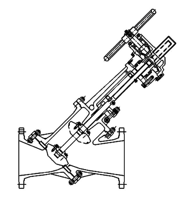
Bottom Body ASTM A216-WCB 2 Gasket Flexible graphite-stainless steel 3 Seat ASTM A105+STL/TCI/Ni-Hard 4 Disc ASTM A105+STL/Ni-Hard 5 Stem ASTM A276-420/17-4PH
6 Upper Body ASTM A216-WCB
7 Packing Flexible Graphite
8 Bonnet ASTM A216-WCB
9 Stem Nut B150 C61900 10 Hand Wheel FCD450
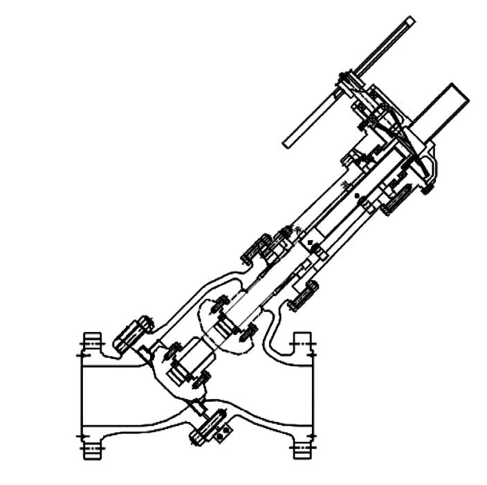
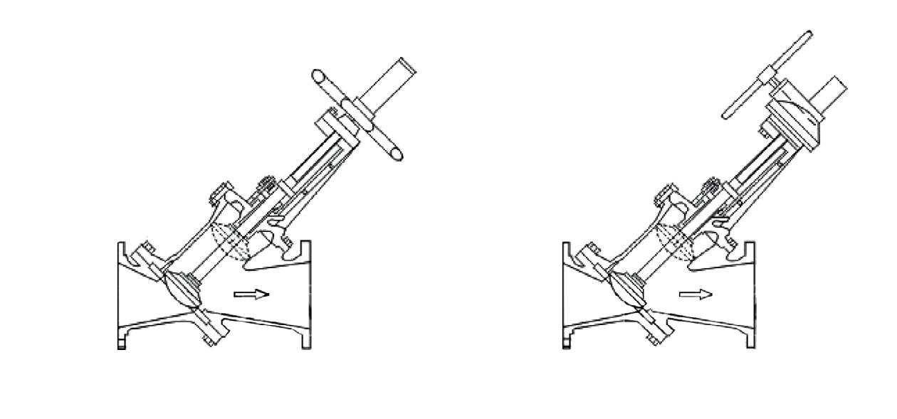
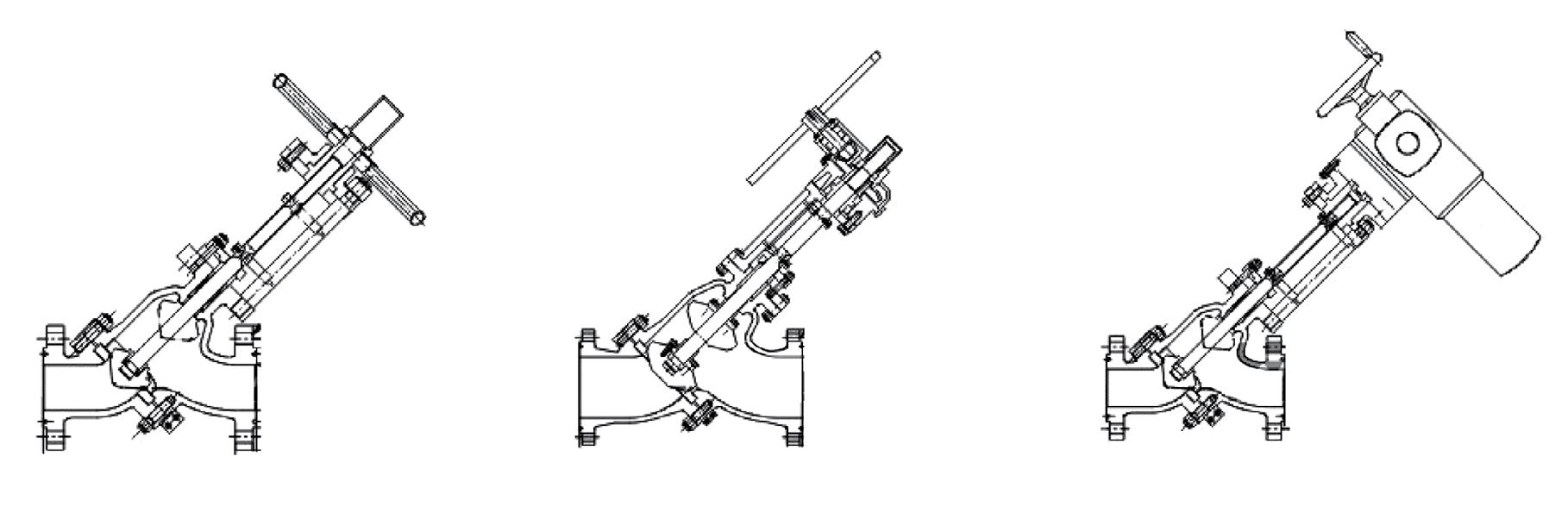
In addition to the flat bottom discharge valves and pipe connection discharge valves, APV provides angle type discharge valves. The angle type discharge valves feature easy operation, convenient maintenance and trim replacement. This type of valve is particularly suitable for aluminium oxide manufacturers.
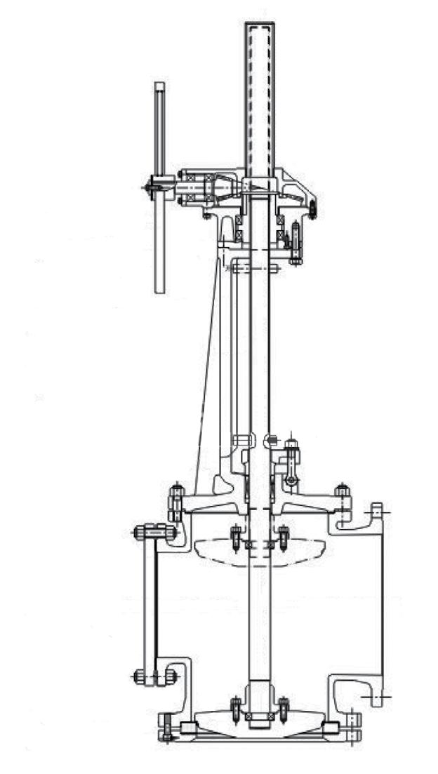
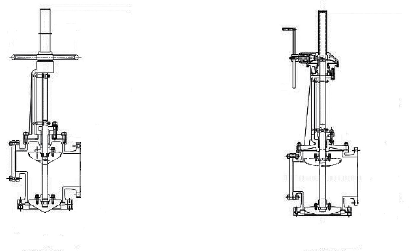
In dual seated gate valves it is necessary to provide a means to prevent over pressurisation due to thermal expansion of trapped fluids inside the valve body. This expansion can cause pressures that exceed the valve materials’ strength causing excessive leakage or actuator failure. The over pressurisation can be avoided with an internal hole or an external equalising pipe which makes the valve unidirectional. Other solutions are as follows –
The equalising pipe connects the valve’s center cavity to the inlet end of the valve allowing fluid displacement. The isolation valve in the equalising pipe is kept open during normal operating conditions. The isolation valve is closed when required for hydrostatic testing or other reason. A combined by-pass with equalising pipe can also be installed to permit the pressure relief in center cavity even with by-pass closed.
“Y” Stop Check & “Y” Lift Check Valves are provided with an equalising pipe connecting the area above the disc to the valve outlet. The equalising pipe eliminates any pressure build up over the disc allowing the higher pressure below to fully open the disc. This full disc lift reduces pressure drop and the required minimum flow to fully open the valve.
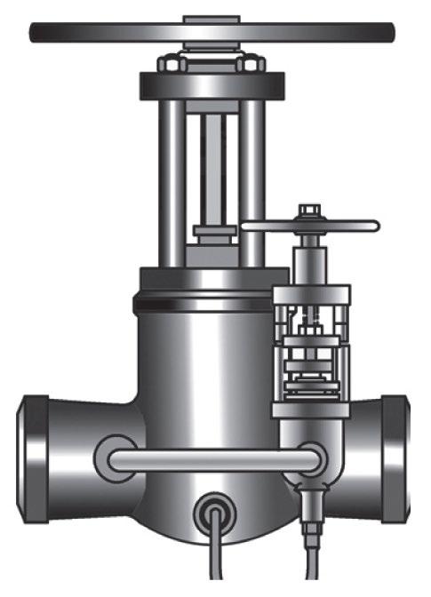
Equalising By-pass
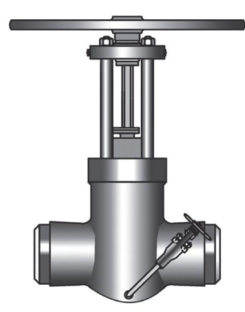
Equalising pipe with isolation valve
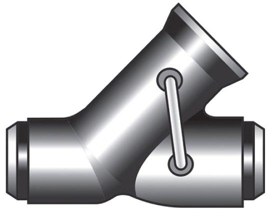
Equalising pipe
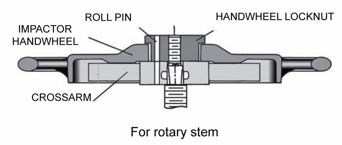
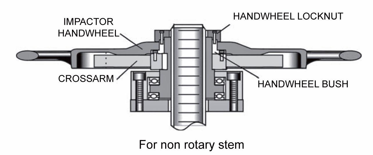
IMPACT HANDWHEEL
Larger size valves (mainly Globe & Stop Check Valves) require an impact hand wheel, when a bevel gear actuator is not required.
By-passes serve two purposes. They are used in steam service to warm-up the line before the main valve is opened. They are also used on steam and other lines to balance the pressure on both sides of the main valve wedge or disc to aid in opening a large valve.
Valves can be furnished with all welded-on by-passes when specified. By-passes are equipped with a single OS&Y globe valve with a pressure/temperature rating and corrosion resistance equal to or exceeding that of the main valve.
Main valve size 1 1/2”-4” 5”-8” 10”-36”
By-pass size 1/2” 3/4” 1”
By-passes on valves 4” and larger are furnished to comply with MSS Standard Practice SP-45, Series A.
Gate valve by-passes shall be regularly attached to the side of the main valve with the stems of both valves parallel and pointing upward (between locations A & B).
Globe valve by-passes shall be regularly attached to the right side of the main valve with the stems of valve parallel and pointing upward. The right side of the globe valve is the side at the right when facing the flow port which leads to the underside of the disc (between location E & F).
Bleed, drain and by-pass piping can be furnished with manual or remote actuated valves, as required.
Where service conditions warrant larger-than-standard by-passes, it is recommended that the installation of the by-passes be around the main valve.
APV valves can be furnished with drain connections at any of the locations shown below. Standard drain connections are the same size as shown below and are drilled, tapped and plugged.
Main valve size 1 1/2”-4” 5”-8” 10”-36”
Drain size 1/2” 3/4” 1”
However, “special request” drain connections can be furnished with threaded or seal welded 6” long nipples with or without shut-off valves. Complete descriptions of desired configurations should be included in your inquiry.
Bleed valves can be supplied upon request. APV’s standard bleed valve is a gate valve, but other configurations can be furnished.
UL/FM approved fuseable link (Choice of temperatures)
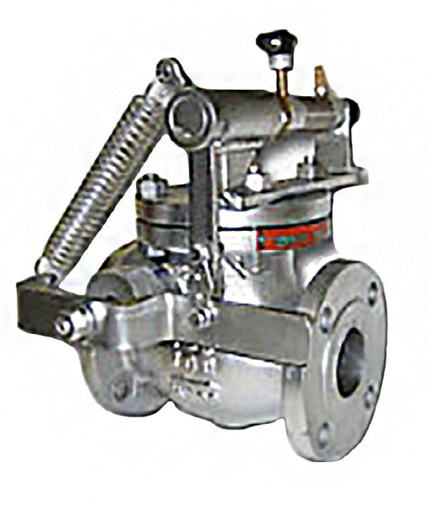
Flow Formulation Using Cv Factors
ENGLISH UNITS
English Units
English Units
Metric Units
Flow Formulation Using Cv Factors
Fluid Flow - Nomenclature
Cv - Flow coefficient for valves and fittings
P1 - Absolute inlet pressure
(PSIA)
P2 - Absolute outlet pressure
(PSIA)
P - Pressure drop in pounds
per square inch (PSI)
Q - Liquid flow in gallons per minute. (GPM)
q’m - Rate of gas flow in cubic feet per minute at
standard conditions, 14.7 psia and 60°F (SCFM)
S - Specific gravity of flowing liquid relative to water at 60°F
Sg - Specific gravity of gas relative to air
s- Number of degrees of superheat for steam in °F
T1 - Absolute inlet temperature
in degrees Rankine (°R)
W - Steam of vapour flow rate in pounds per hour
(LBS/HR)
METRIC UNITS
Metric Units
Fluid Flow - Nomenclature
Cv - Flow coefficient for valves
and fittings
P1 - Absolute inlet pressure
(PSIA)
P2 - Absolute outlet pressure
(PSIA)
P - Pressure drop in pounds
per square inch (PSI)
Q - Liquid flow in gallons per minute. (GPM)
q’m - Rate of gas flow in cubic feet per minute at standard conditions, 14.7 psia and 60°F (SCFM)
S - Specific gravity of flowing liquid relative to water at 60°F
Sg - Specific gravity of gas relative to air
s- Number of degrees of superheat for steam in °F
T1 - Absolute inlet temperature
in degrees Rankine (°R)
W - Steam of vapour flow rate in pounds per hour
(LBS/HR)
FLOW COEFFICIENTS
FLOW COEFFICIENTS - TYPICAL CV FACTORS FOR API 602 TYPE VALVES 150 - 800 CLASS
FLOW COEFFICIENTS FOR 150 & 300 CLASS BOLTED BONNET API 600 TYPE VALVES
NOTES:
(1) Required flow velocity for other fluid different than water = Flow velocity on table x 7.9 SQRT( 1/ density of the fluid), density in lbs per cubic feet. (2) Class 150 only. * Full Port
NOTE: (1)
FLOW COEFFICIENTS FOR 1500 CLASS BOLTED BONNET API 600 TYPE VALVES
FLOW COEFFICIENTS FOR 2500 CLASS BOLTED BONNET API 600 TYPE VALVES
FLOW COEFFICIENTS FOR 900 CLASS PRESSURE SEAL ASME B 16.34 TYPE VALVES
FLOW COEFFICIENTS FOR 1500 CLASS PRESSURE SEAL ASME B16.34 TYPE VALVES
FLOW COEFFICIENTS FOR 2500 CLASS PRESSURE SEAL ASME B16.34 TYPE VALVES
** Thread size & pitch can vary.
ID = BODY SEAT DIAMETER OD1 = STEM MAX DIAMETER OD2 = STEM MIN DIAMETER WP1 = MEDIUM WORKING PRESSURE CWP = COLD MAX. WORK PRESSURE
TH-CL = THRUST FOR WP1 TH-CW = THRUST FOR CWP (MAX CWP)
=
= THRUST FOR STP
TQ-CL - TORQUE FOR WP1 TQ-CW = TORQUE FOR CWP (MAX CWP) TQ-ST = TORQUE FOR STP
Note:- This table is a general guide only, for estimated purposes. All figures can vary depending on trim, bonnet type, handwheel size, disc/wedge type, packing and other factors. It should be used for estimation purposes only as specifications can and do change. Contact us for specifications as and when required. No safety factor included. Torques shown are with graphite stem packing (bolted bonnet design), PTFE packing will be lower torque. The stem size (and therefore pitch, thread, etc.) of gate & globe valves can vary depending on service, required safety factor, packing type, wedge/disc type, etc.
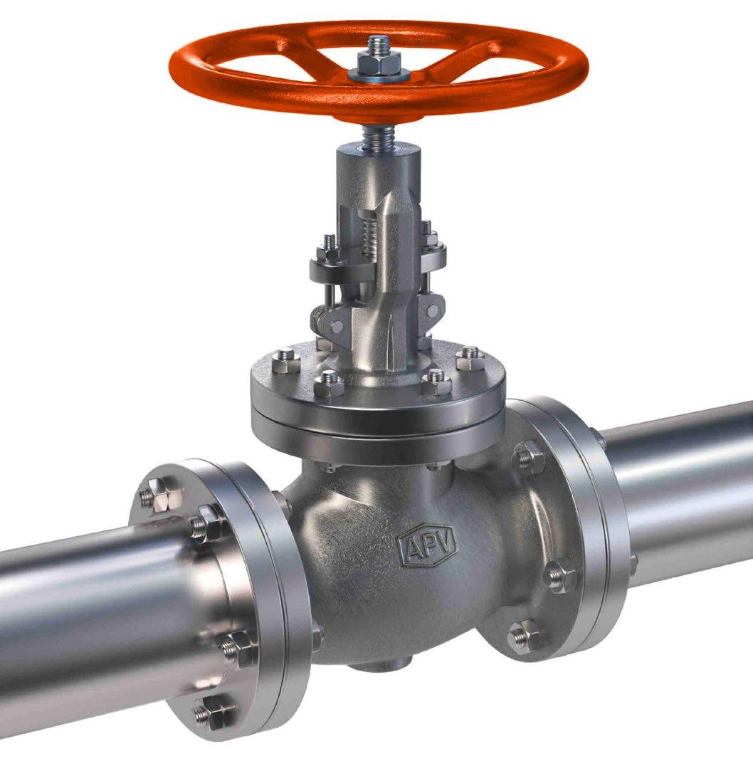
*DL = Double sided. **Thread size & pitch can vary.
ID = BODY
Note:- This table is a general guide only, for estimated purposes. All figures can vary depending on trim, bonnet type, handwheel size, disc/wedge type, packing and other factors. It should be used for estimation purposes only as specifications can and do change.
Contact us for specifications as and when required. No safety factor included. Torques shown are with graphite stem packing (bolted bonnet design), PTFE packing will be lower torque. The stem size (and therefore pitch, thread, etc.) of gate & globe valves can vary depending on service, required safety factor, packing type, wedge/disc type, etc.
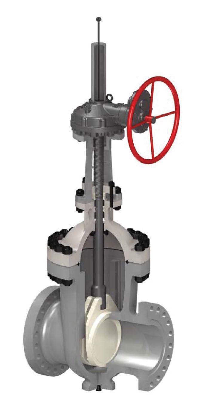
Australian Pipeline Valve don’t consider in our design the following factors of risk
1. Australian Pipeline Valve ‘Standard’ valves can be used in a temperature range between -29 to +490°C. (Note, pressure limitations apply above 38°C refer to Pressure/Temperature charts.) For service temperatures below -29°C valves construction materials shall be submitted to an impact test at the minimum service temperature. For temperatures above and below the standard range, special seals need to be specified by the client.
2. The onus is on the customer to specify all materials of construction and service conditions. Australian Pipeline Valve shall assume standard materials and conditions if not otherwise specified.
3. Australian Pipeline Valve ‘Standard’ valves are not equipped with devices suitable to avoid internal over-pressures caused by incorrect operations of process or by-fluids & liquids subjected to an increase of volume and/or pressure (these devices, such as the over-pressure hole in the gate or safety seats are available upon request).
4. Australian Pipeline Valve ‘Standard’ valves are not designed with special devices to withstand a sudden thermal jump (thermal shock).
5. In general Australian Pipeline Valve ‘Standard’ valves are not mechanically designed to bear overloads due to exceptional atmospheric or natural phenomenon’s (such as earthquakes).
6. In general Australian Pipeline Valve ‘Standard’ valves are not designed to bear loads on flanges, on pipe connections or pipe-line.
7. In general Australian Pipeline Valve ‘Standard’ valves can’t withstand ice inside their bodies (in this case the user has to consider the optional stem extension for insulating, avoiding the presence of residual product inside the valve).
8. Australian Pipeline Valve ‘Standard’ valves are not suitable for low temperature service below -29°C (-20°F) unless supplied (in a suitable body material) with cryogenic stem extension and other modifications, (available on request).
9. Australian Pipeline Valve ‘Standard’ valves are suitable for ‘industrial’ oxygen (not medical) service when supplied degreased and packed in polyethylene bags only.
10. The compatibility between the valves construction materials and medium is selected by the user. The user is ultimately responsible for verifying the compatibility between medium and materials.
11. Abrasive or dirty service applications need to be considered and stated at time of order.
Before installing the valve onto the pipe-line it is mandatory, for the user, to verify the compatibility of the valve with service conditions (medium, temperature and pressure). With reference to standard valves held in stock, the reseller and end user will have to assure themselves of the compatibility between the valve and the conditions required by the customer. Australian Pipeline Valve gate valves must be only used for on-off (fully open/fully closed) service.
Before using the valve in a potential explosive atmosphere it’s necessary for the customer to -
• To verify the correct type of valve and operator is specified.
• To verify the compatibility between the valve and the zone in which the valve should be installed
• To foresee the pipe-line ground condition on which the valve should be installed
• To check that the temperature if the valve surface is not higher than the flammable point of the atmosphere in which the valve is installed (in this case specify an insulating cover device for the valve and an extension for the operator)
• To avoid mechanical knocks during the installation that may cause sparks.
Australian Pipeline Valve cannot be held responsible for damage caused by use of the product for any reason, especially if it is improper use or modified.
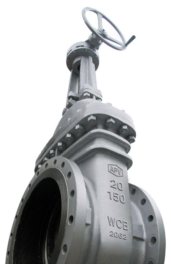
“Australian Pipeline Valve produces isolation, control and flow reversal protection products for severe and critical service media in utility, steam, pipelines, oil & gas and process industries. APV valves and pipeline products form the most competitive portfolio in the market.”