STRUCTURE SEPTEMBER 2025
NCSEA | CASE | SEI
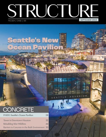
Seattle's New Ocean Pavilion
CONCRETE INSIDE: Seattle's Ocean Pavilion
38
Tower in Downtown Houston 32 Rebuilding After Wildfires 44 Barriers to Concrete in the Built Environment 50
STRUCTURE SEPTEMBER 2025
NCSEA | CASE | SEI
Seattle's New Ocean Pavilion
CONCRETE INSIDE: Seattle's Ocean Pavilion
38
Tower in Downtown Houston 32 Rebuilding After Wildfires 44 Barriers to Concrete in the Built Environment 50