
3-phase alternating current the public mains, motors, safety


3-phase alternating current the public mains, motors, safety
www.revma.se
s-b@revma.se
Author: Sven-Bertil Kronkvist
Editor: Agneta Kronkvist
Acknowledgement!
The author and Revma Education want to thank Fredrik Rosberg at the Swedish Defense Forces Technical School, for initiatives and views of the Swedish textbooks, now translated to English.
Revma Education textbooks in electricity and electronics are designed for different ways of learning, with shorter or more comprehensive explanatory texts, step-by-stepexplained calculations, and a balanced number of test-yourself exercises.

English versions of Ellära grunder
1-fas växelström
3-fas växelström
The author, Sven-Bertil Kronkvist, has taught electricity, electronics, and automation more than thirty years, been lecturer in subject methods at teacher training collages in developing countries, written and implemented national curriculums. The experience of how students with different prerequisites learn electrical thinking is the basis for these books.
A few things before you start reading
Quantities, units, numbers, and mathematical signs are placed within brackets. The somewhat unusual manner is meant to make it easier for the reader to recognize quantities and numbers, and for no other reasons.
Example: ……. the reference arrow for (U) has a (+) and a (-) side …… ……. if the resistance is (1,5Ω) and the ………...
Also note that decimal commas are used instead of decimal points. Example: 10,15 instead of 10.15
Copyright!
This work is protected by the Copyright Act! Copying exceeding teachers' right to copy for educational use under the BONUS agreements is prohibited. Anyone who violates the Copyright Act can be prosecuted by a public prosecutor and sentenced to a fine or imprisonment for up to two years and be sentenced to pay compensation to the author or the right holder.
Sven-Bertil Kronkvist and Revma Education
This book explains the 3-phase concepts and the use of 3-phase in the general power grid. Since three-phase technology is based on knowledge of DC and single-phase alternating current, there is a summary at the end of the book. The author recommends reading the summary first, and then have it as a reference.
Whatever the choice is, start to read about the basic circuit below.
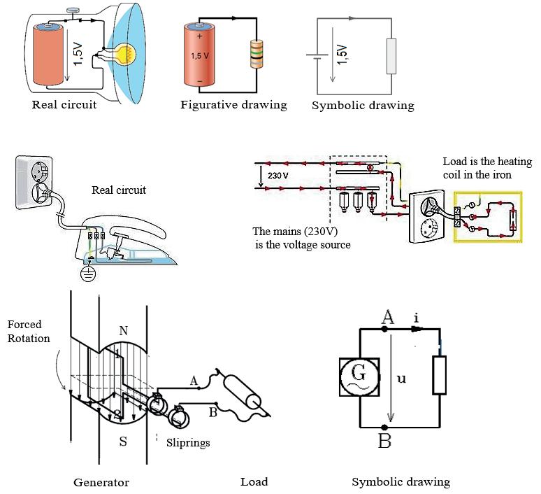
It is worth remembering that all electrical circuits, both DC and AC, always consist of a voltage source with an internal resistance (impedance) and a load.
Thinking electricity involves being able to see the basic circuit even if the voltage source and load vary in form and characteristics.
The resistance In the lamp

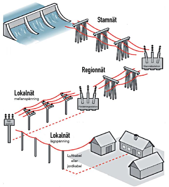
In the public mains are the power plants using 3-phase generators to convert various energy forms to electric energy. The generators produce three time-shifted voltages that each, or jointly, can drive current through loads.
An up-transformation of the generator voltage is made in the power station. Notice the high values, 400kV (400,000V), 130kV and 10 - 20kV between the power plant and the substations. With high voltage, the current in the wires can be smaller. In this way, voltage losses across the wires will be less.
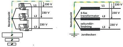
In the last substation before the consumers, a transformation to 400/230V is made with a 3-phase transformer.


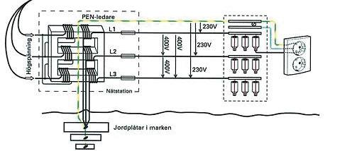
The high voltage of the mains is connected to the primary windings of a 3-phase transformer, while the secondary windings are connected to fuse boxes of electricity consumers, and from there to wall sockets or other connection devices.
If we change from a figurative to a symbolic drawing and only draw the secondary windings, we see how they are connected to a common neutral point connected to ground. The neutral point is therefore often called ground.

Three phase wires, L1, L2 and L3, are connected to a fuse box, as well as a PEN wire that is a combined Protective Earth and Neutral wire.
In the fuse box the PEN wire is divided into separate protective and neutral wires before they are connected to wall sockets, three-phase plugs, and other connecting points.
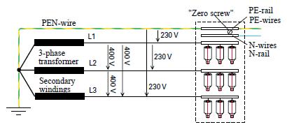
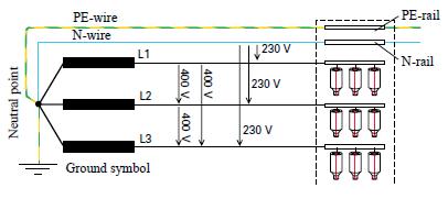
Five-conductor systems have separate PE and N wires starting from the neutral point. Please note that PE and N wires must never be combined after the fuse box, neither in 4- or 5-conductor systems.

zero screw is used to split the protective and neutral wires during insulation test.

Voltages at the consumer side
In the consumers fuse box there are three main-voltages of 400V and three phase-voltages of 230V.
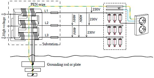
Note that the main voltages exist between the three phase wires and that each wire are connected to a separate phase rail, to which one side of the fuses are connected.
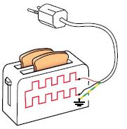
The other side of the fuses are connected to loads, e.g., toasters via single-phase wall sockets.
The (230V) phase-voltages are found between the PEN-wire and respective phase-wire
Both the main- and phase-voltages are given in RMS (root mean square) values.
The peak values of the phase voltages are equal to the RMS (230V) value multiplied by the square root of two.
325V)2(230 =⋅
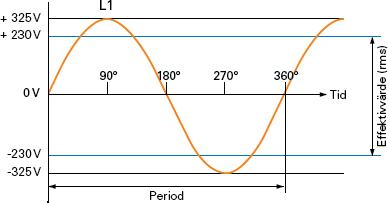
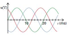
Period: 20ms

Ratio between main- and phase-voltage
An important relationship that should be remembered is that the main voltage is (√3) times greater than the phase voltage (230 ∙ √3 = 400V).
Period and frequency
A period lasts (20ms). This means that the sinusoidal voltage curve is repeated fifty times in one second, but instead of saying there are (50) periods in one second, it is said that the frequency of the voltage is (50Hz).
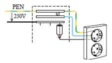
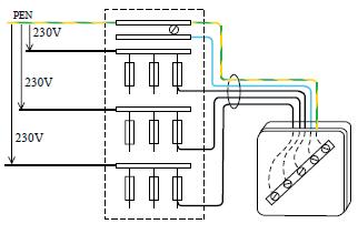
Each of the three phase-voltages of (230V) can be connected via a fuse to single-phase sockets. Notice how the incoming PEN conductor is divided into PE and N wires in the fuse box and how they are connected to the single-phase socket.
Connection of a 1-phase socket
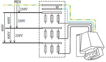
In addition to the N and PE conductors, all three phase-voltages are connected to three-phase sockets via three fuses. In three-phase sockets, the electricity consumer therefore has access to both the phase-voltages of 230V and the main-voltages of 400V between L1, L2 and L3.
Connection of a 3-phase socket
Permanently installed electrical appliances, such as stoves and heating pumps, are often connected to the mains via a junction box. Some devices are connected as single-phase, others as two- or threephase loads. More options do not exist, and it is definitely worth learning how it is done.
Connection of a 3-phase junction box
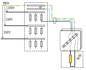
Imagine an electric radiator. They may have one, two or three heating coils. They act as resistors and can often be connected in different ways. This is how they are connected as a single-phase load.
Notice that three wires are needed. A phase wire via a fuse, a blue neutral wire, and the yellow-green protective wire. The voltage across the load is 230V.
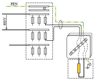
Two-phase loads are also connected with three wires, two phase wires via two fuses, no neutral wire, but the yellow-green protective wire shall be included.
The voltage between two phases, and thus also across the load, is 400V.
Test -yourself -3
a) Record the expected measurement results in the displays of the multimeters in the first (1,2,3 measurement situations.
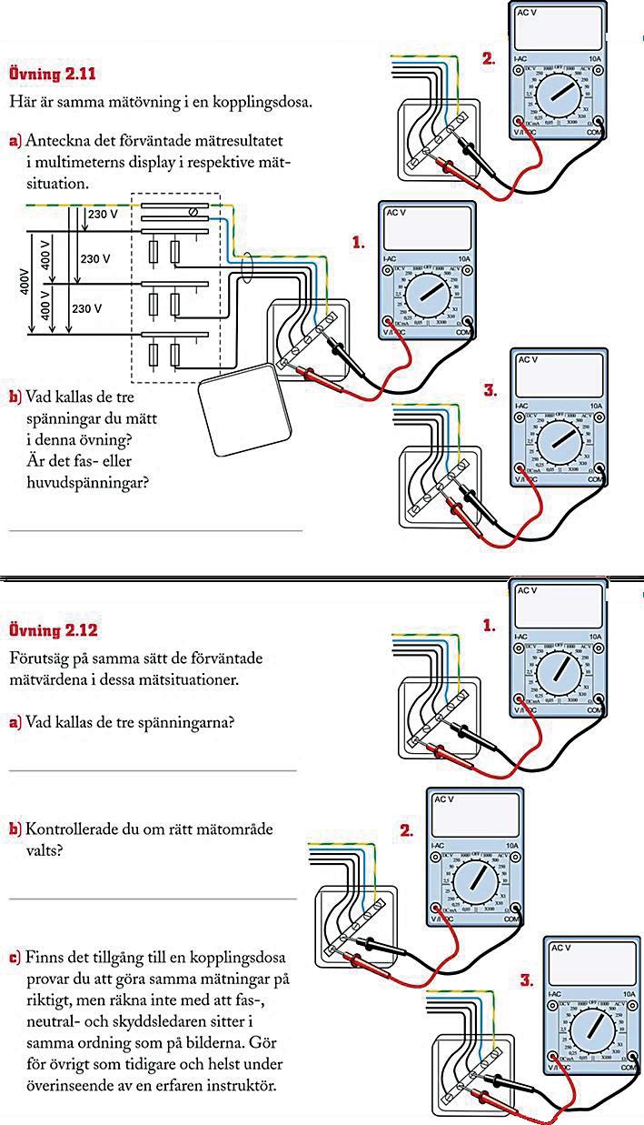
b) Was it the phase- or the mainvoltages you measured?
c) Record the expected measurement results in each display.
d) Was it the phase- or the mainvoltages you measured?
e) Did you check if correct measuring range was selected?
f) If you have access to a junction box, try to make the same measurements for real! Do not expect phase, neutral and protective wires to be in the same order as in the pictures.
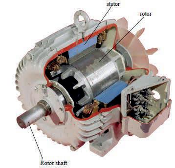
Electric motors are machines that convert electrical energy into mechanical. There are both DC and AC motors, and in both groups, there are different types with special operational characteristics. Among the AC machines, three-phase asynchronous motors are most common. They are very reliable, and it is easy to regulate their speed.
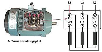
The main parts of all electric motors are a stator and a rotor with associated drive shaft. In a 3-phase asynchronous motor, the stator has three windings that generate rotating magnetic fields when connected to 3-phase voltages. The magnetic field, in turn, exerts a force on the rotor which make the drive shaft to rotate.
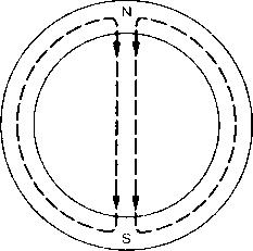
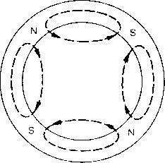
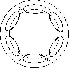
The rotating magnetic field can consist of 2, 4, 6, 8 or more north and south poles depending on how the stator windings are positioned around the stator.
This is the magnetic field images for 2-, 4- and 6-pole machines.
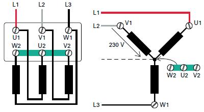
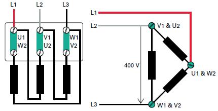
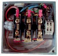
Both sides of the stator windings are accessible in the connection box and are marked as in the figure below. By using jumpers, it is easy to connect the stator windings as either Y- or D-coupled. The connections are called so because they resemble a Y and D respectively in electrical drawings.
Across each winding, between L1, L2, L3 and the midpoint, there are phase voltages (230V). The midpoint can be connected to the neutral point, but it is not necessary as the sum of the three phase currents is zero for balanced loads due to the phase differences.
Across each winding are the main voltage (400V) and it is not possible to connect a neutral wire.
Please note that the motor windings must always be intended for the voltage they are connected to.
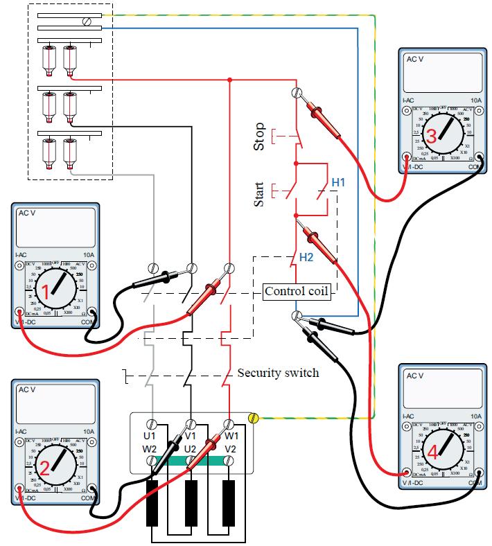
What do the multimeters (1,2,3,4) show if you pressed the start button before taking the readings of the four multimeters? Write the answers in the displays.
Remember that the contacts are depicted in unaffected position. You must think for yourself which contacts are affected when the start button is pressed. Feel free to draw the new modes directly in the drawing.
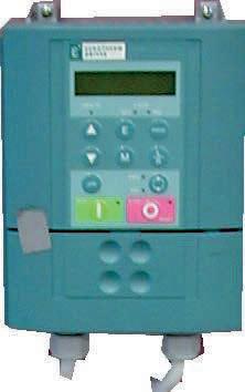
An increasingly common and better way to start AC motors in a soft way is with frequency converters. The input AC voltage is rectified, and then with help of electronics, the DC voltage is converted into "artificial" three-phase voltages whose frequency can be changed manually or with a programmed sequence.
The motor can thus be started at a low speed and gradually increased without large starting currents and with a maintained high starting torque.
Motor circuit with AC drive
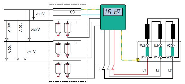
The frequency converter is mounted between the fuse box and the safety switch.
Test-yourself-11
a) Is the motor Y- or D-coupled?
b) What is the speed if it is a motor with 4 poles?
Guidance: Use the speed formula and read the frequency on the frequency converter.
All generators exploit the induction phenomenon discovered by Michel Faraday in 1831-32.
In windings enclosing a magnetic flux that changes magnitude or direction, is a voltage induced.

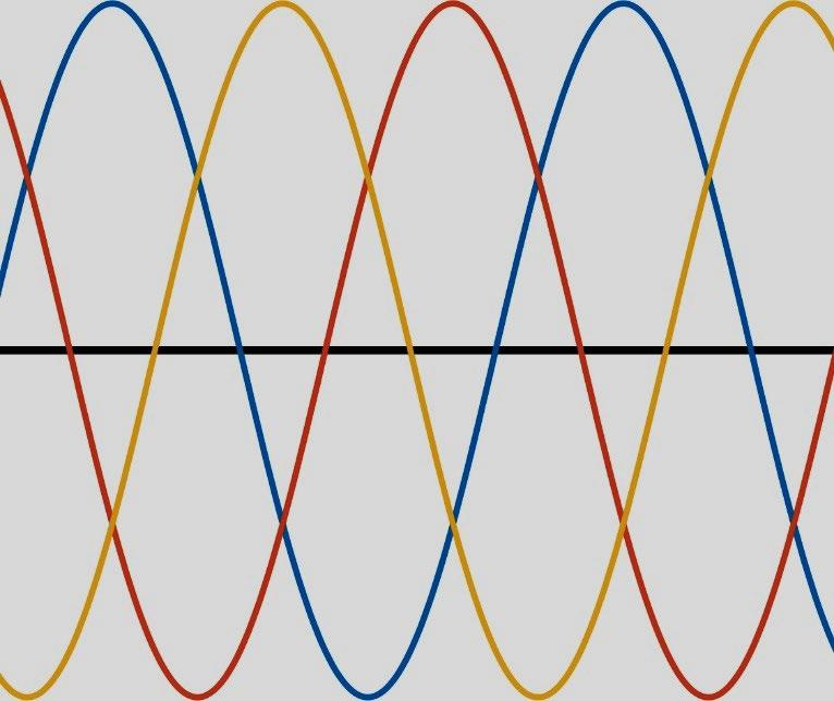
3-phase alternating voltages
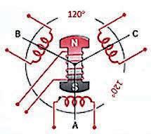
In the model of the three-phase generator above, the magnetic flux in the three generator windings changes as the electromagnet rotates.
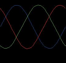
The three sinusoidal voltages induced during the rotation are phaseshifted (120°) relative to each other because the windings are arranged that way.
Each winding is a separate single-phase generator that can drive current through a load.
3-phase or three 1- phase circuits
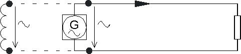
The generator winding is here replaced with a generator symbol.
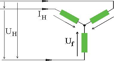
In the drawing below we can see how a three-phase generator is three separate single-phase generators connected to separate loads. The Yshaped drawing illustrates the (120°) displacement of the generator windings and thereby the three phase voltages (Uf).
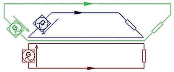
Uf = Phase voltage 230V
IH = Head current
In the public mains, the loads are not directly connected to the generator windings. There are both fuses, transformers and more between the generators in the power plants and the electricity consumers.
Formula for apparent power in three- phase loads
Apparent power in each phase load
Substitute

3-phases
Apparent power in three phases
Resistive phase loads
In resistive phase loads there is no phase shift between the voltage across the load and the current. Hence the apparent power is equal to the active power and there is no reactive power either.
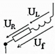
Formula for active power in inductive loads

Active power in each phase load
Substitute
Substitute
3-phases


Explanation


If, for some reason, a person simultaneously become in contact with both the phase voltage (230V) and ground, there will be a current passing through the body, just like in any other load.
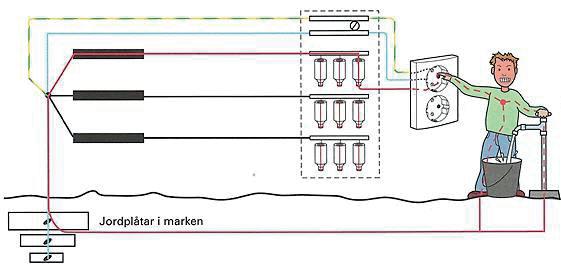
The common neutral point of the power grid is in contact with everything touching the ground, such as pipelines, water taps, radiators, sinks, concrete floors and more. Depending on the size of the current, its path through the body and the connection time, there is a risk for the connected person to get cramps, burns, breathing difficulties, and eventually deceases. Body resistance varies but can be as low as (1000Ω). Calculated with Ohm's law, it gives a current of (0,23A) at a voltage of (230V). This is significantly more than the (0,020–0,030A) that the body can cope with for a short time.


The electrical circuit
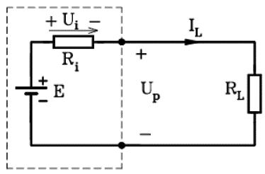
The simplest electrical circuit consists of a voltage source connected to a load resistance according to the drawing.

E.m.f and battery symbol

Resistor symbol
Reference arrows and designations of quantities
To show how the currents flow and how the voltages are distributed in circuits are reference arrows and designations for quantities such as the pole voltage (UP), the internal resistance (Ri), the resistive load (RL), etc.
Arrows for voltage drops points from a higher towards a lower voltage level. The plus side has higher voltage than the minus side.
Reference arrows for current indicate the direction of the current flow in wires and components.
Reference arrows and designations helps the electrical thinking and should be used diligently, both in calculations and analysis of circuits.
Rules
Current flow exists only in closed circuits.
The current always flow from the positive terminal of the voltage source to its negative terminal.
The current starts and ends in the entire circuit at the same time.
Al the current flowing out from the positive terminal of a voltage source is flowing back to the negative terminal.
A voltage source can always be considered as a constant electro motoric force (e.m.f.) in series with an internal resistance (Ri).
Note that the e.m.f. in this book is denoted E in some drawings.
The terminal voltage (UP) is dependent on the internal voltage drop across the internal resistance (Ri), according to:
UP = E – Ui where Ui = IL. Ri (The formula refers to the drawing at the top)
Ohm's law
The relationship between the current passing through a resistance and the voltage drop across the resistance is specified by Ohm's law.
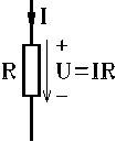
I U R = I = current in A (ampere)

U = voltage in V (volt)
R = resistance in Ω (ohm)
Test-yourself-1
Multimeter 1: 230V
Multimeter 2: 0V
Multimeter 3: 230V
Test-yourself-2
a) Adjusted for AC voltage
b) Measuring range at least 230V
c) It should be YES
d) If YES, measure in a wall outlet
Test-yourself-3
a) Multimeter 1: 230V
Multimeter 2: 230V
Multimeter 3: 230V
b) Phase voltages
c) Multimeter 1: 400V
Multimeter 2: 400V
Multimeter 3: 400V
d) Main voltages
e) Hopefully YES
The measuring range should be at least 400V
Test-yourself-4
a) 8
b) 3
c) 6
d) 3
e) 6
Installation exercise page 15
a) 1: Phase wire
a) 2: Neutral wire
a) 3: Protective earth wire
a) 4: Lamp socket
a) 5: Switch
b) 1: Protective earth wire
b) 2: Neutral wire
b) 3: Phase wire
b) 4&5: Switches
Test-yourself-5
a) 1500 rpm
b) 1000 rpm
c) The motor speed decreases
d) Change the frequency
Test-yourself-6
a-b-c) All motor windings should have the same value, in the range of 15 - 30Ω
Test-yourself-7
a) Y-coupled
b) 230V
c) 4 to 8 times the operating current i.e., 6,8A – 13,6A
Test-yourself-8
Multimeter 1: 400V
Multimeter 2: 400V
Multimeter 3: 230V across the control coil
Multimeter 4: 230V across the control coil
Test-yourself-9
a) After approx. 30s, longer if the motor is unloaded
a) After approx. 1,5 minutes, longer if the motor is not loaded
Test-yourself-10
a) The motor remained disconnected
b) Reboot could be done manually
Test-yourself-11
a) D-coupled
b) Use the synchronous speed formula and insert f = 16Hz.
Synchronous speed = 480 rpm
Test-yourself-12
a) The exercise is successful when the motor is connected to a single-phase socket and rotate.
b) The exercise is successful when the rotation is reversed
Test-yourself-13
Three wires, one phase, one neutral and one protective earth wire.

3 - phase alternating current
3 - phase concepts are explained step-bystep, aiming to give the reader ability of electric thinking and methods for analysis and calculations.
Formulas and mathematics are explained thoroughly to make also unaccustomed mathematicians to feel comfortable.
Most sections have test-yourself exercises.
The book ends with a summary of DC and 1-phase theory for rehearsing and as reference. www.revma.se contact: info@revm.se
ISBN 978-91-8059-845-3
EAN-cod 978-91-8059-845-3.svg