1 ARCHITECTURE PORTFOLIO
2019-2024
Shaun Varghese
Urban fabric
Semester 10- Design Dissertation
Proposal for the North Wing Extension to the Mumbai City Bahu Daji Lad Museum at Byculla, Mumbai.
6-21
Community
Semester 4- Architectural Design Studio
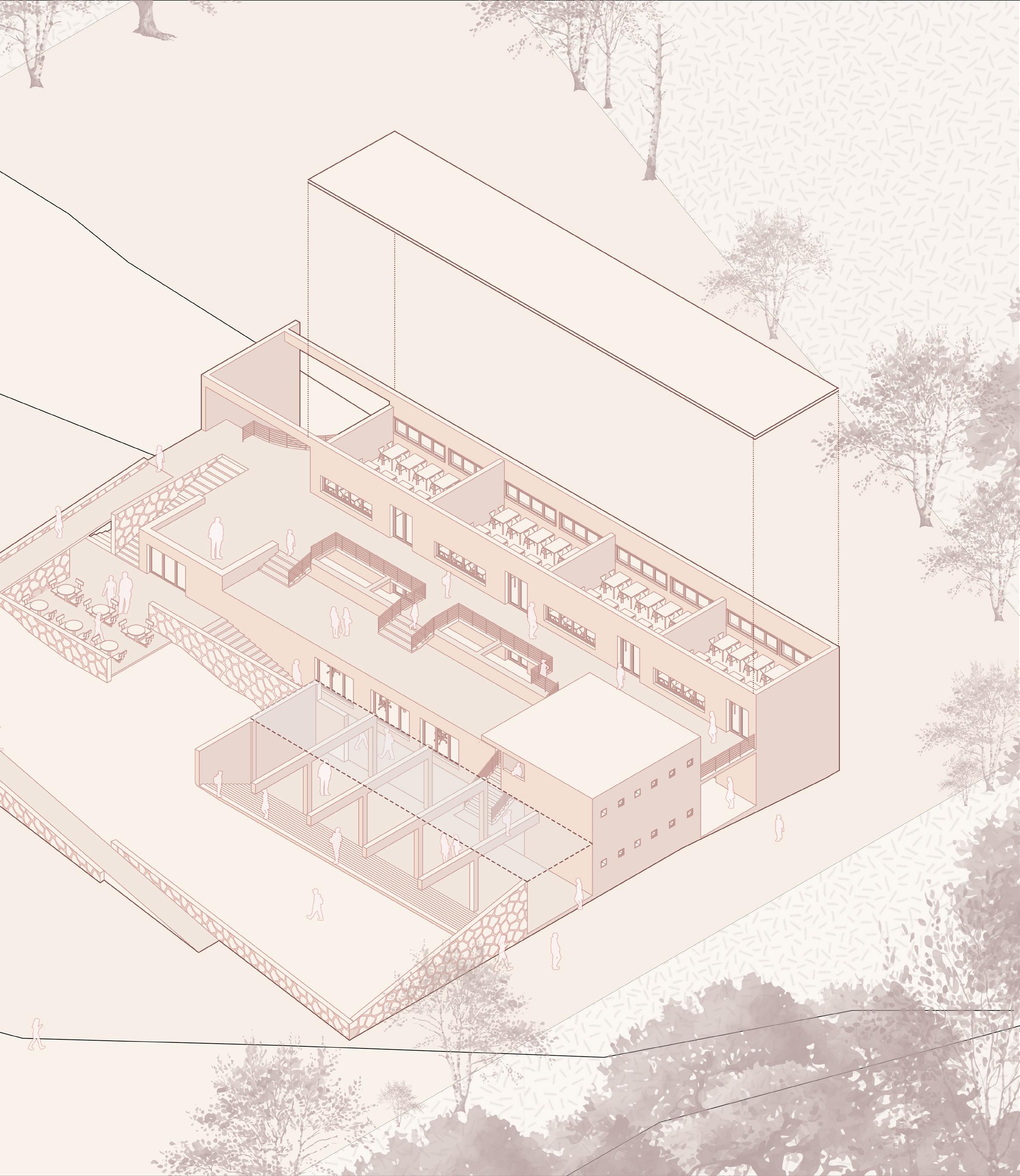
Primary School and Community Centre at Jambhe, Maharashtra.
22-29
2
Vidyamandir Gandhianism Drawings
Internship project at Footprints E.A.R.T.H.
The Gandhi Aashram Shaikshanik Sankul (Education Hub) at Sabarmati, Gujarat.
Internship project at Footprints E.A.R.T.H.
A New Wing for the BAPS Vidyamandir (School) in Nadiad, Gujarat.

Collection of Miscellaneous drawings done during my internship at Footprints E.A.R.T.H. including working drawings; layouts and Renders.
3
40-43 44-53
30-39
4
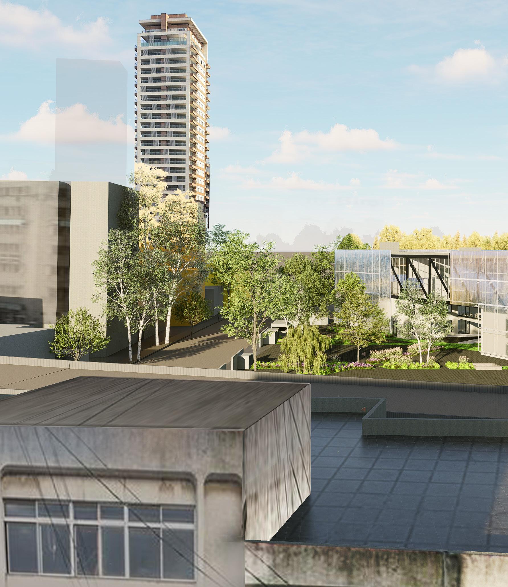
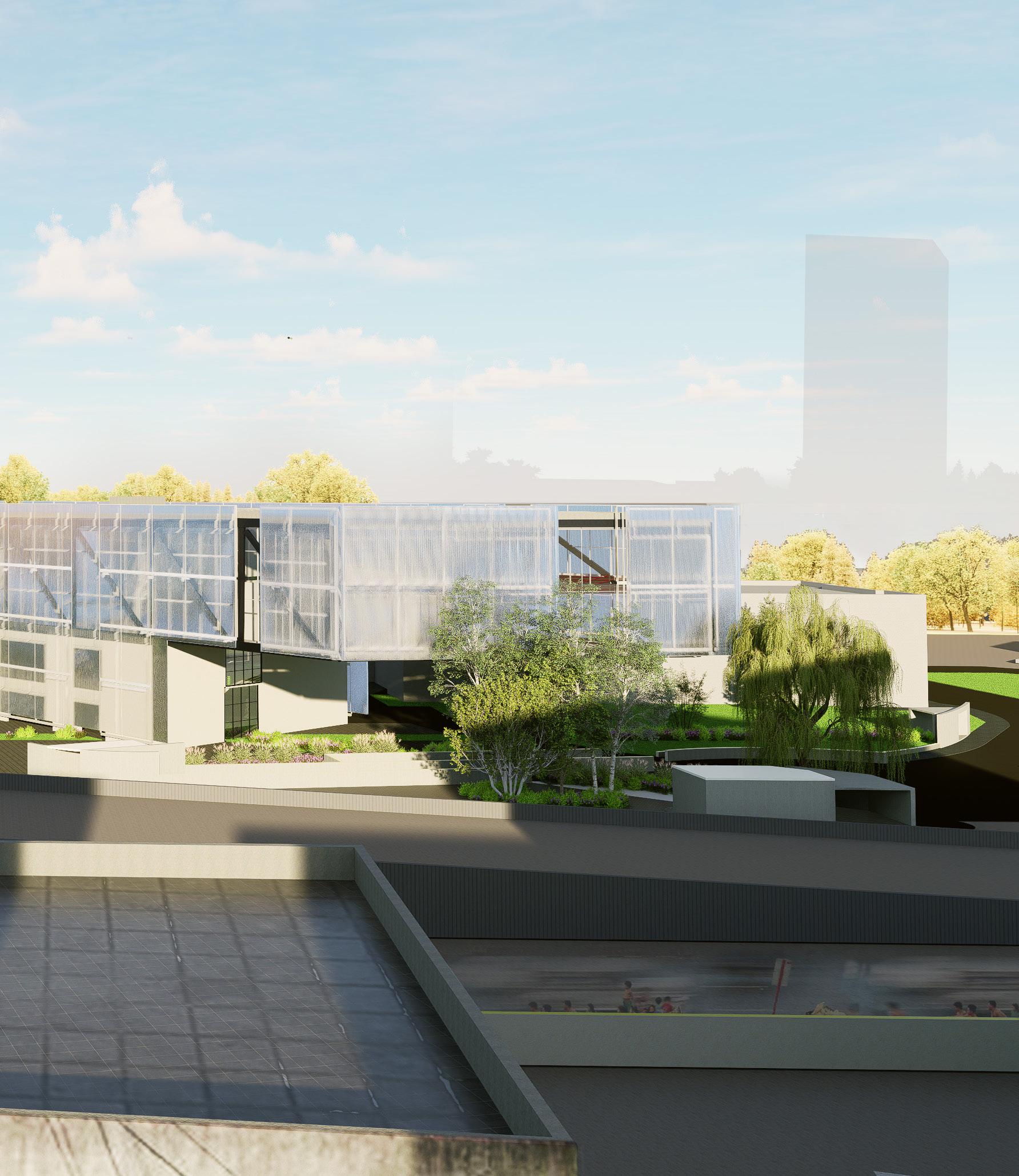
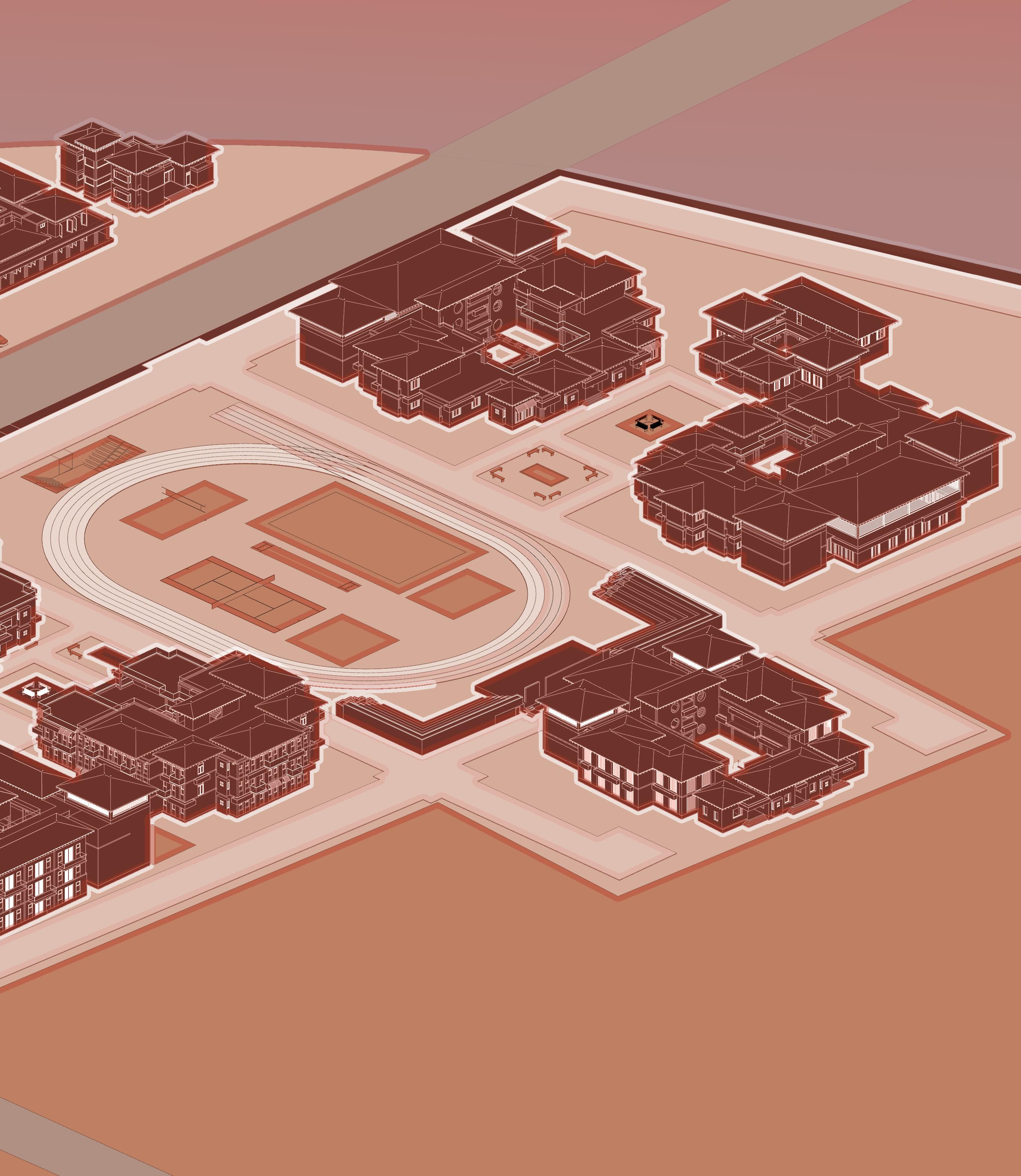
urban fabric
North wing extension to the Mumbai city Bhau Daji Lad Museum, Byculla, Mumbai
Location: Jambhe, Maharashta
Software used: Revit, AutoCad, D5 Render, Photoshop
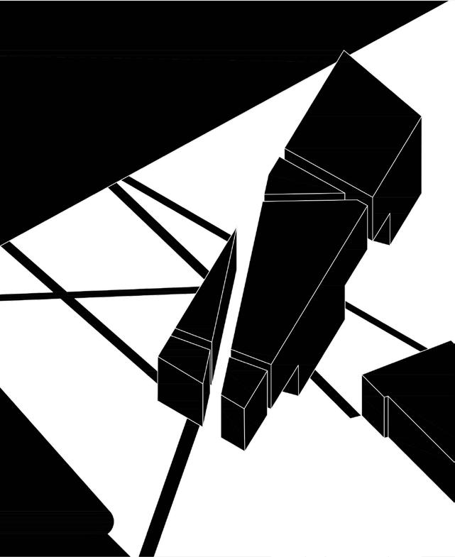
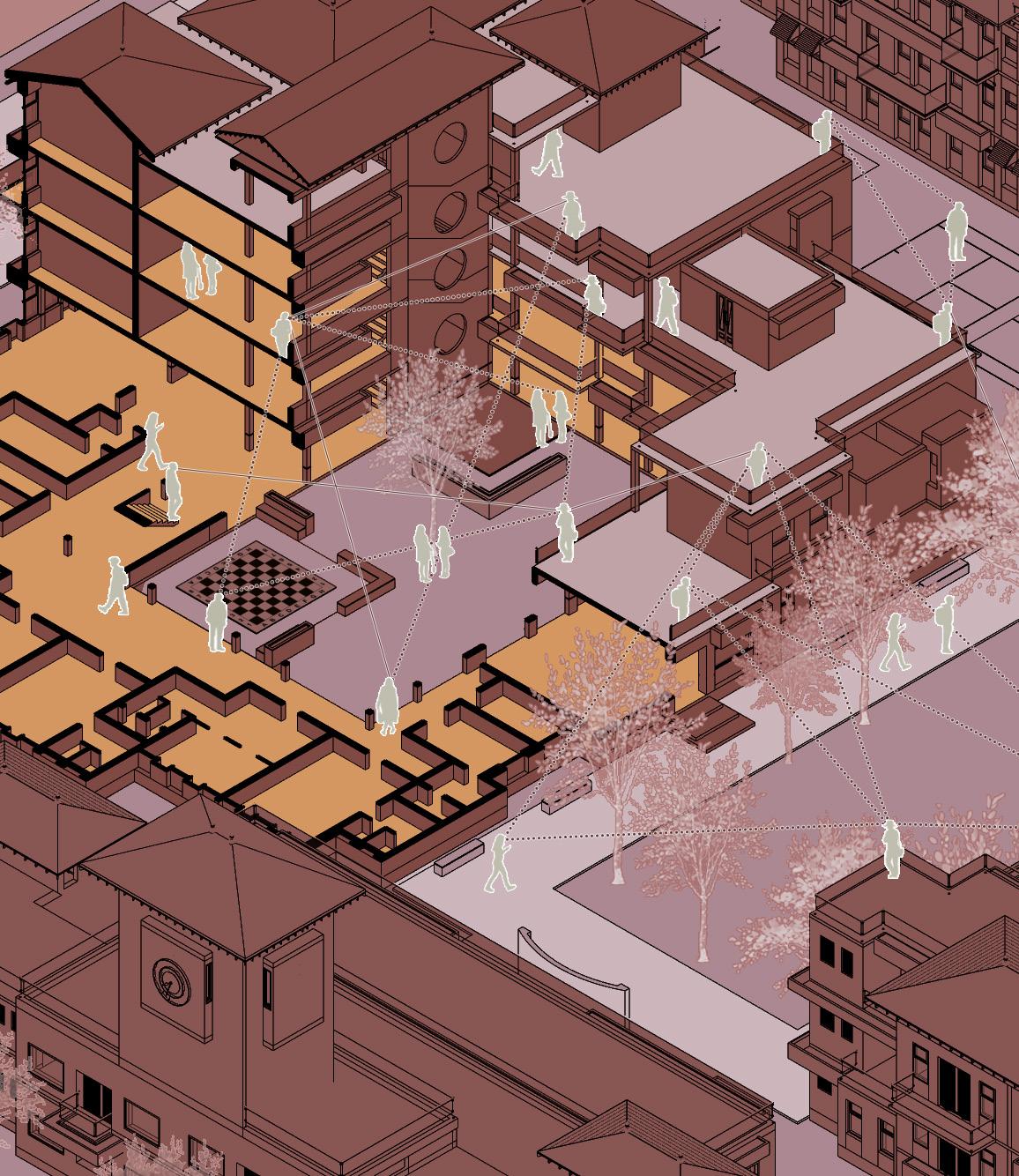
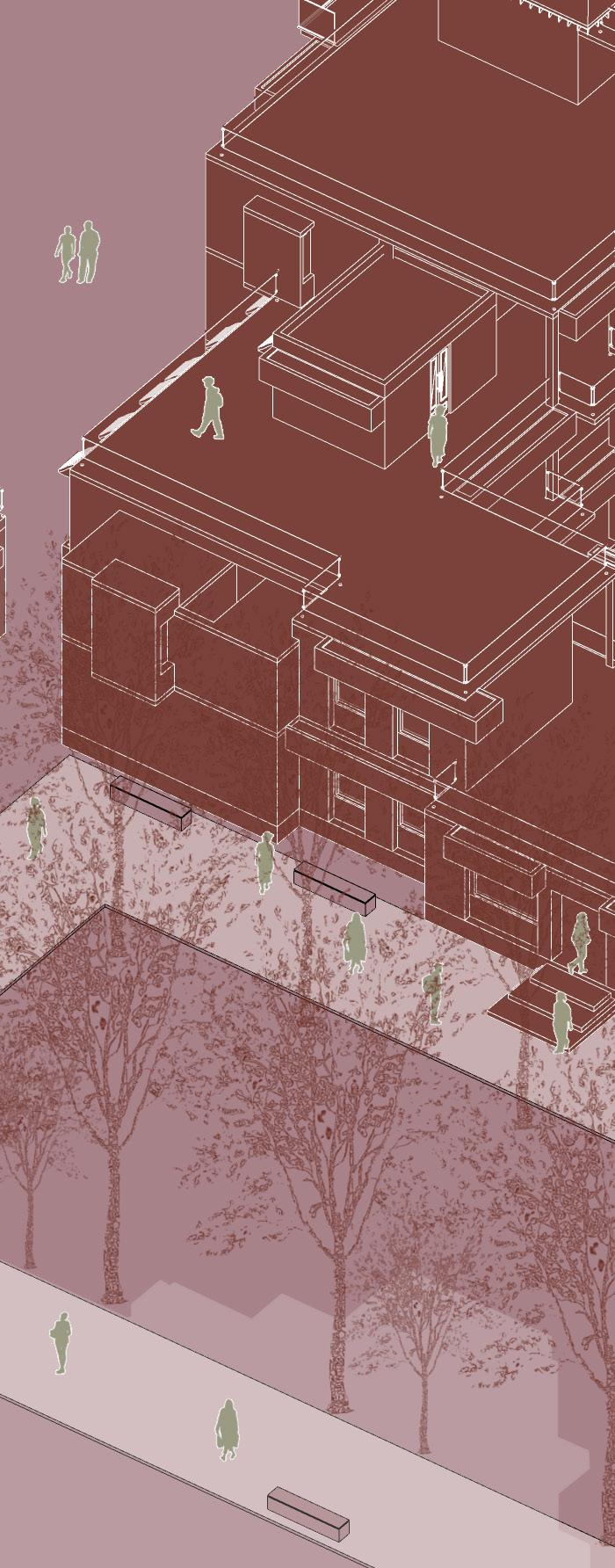
Central to the design was the inquiry, “How does an institutional structure interact with its surroundings in the urban fabric?” This question led to an exploration of the Deleuzian concepts of ‘becoming’; ‘the fold’ and ‘rhizome’.
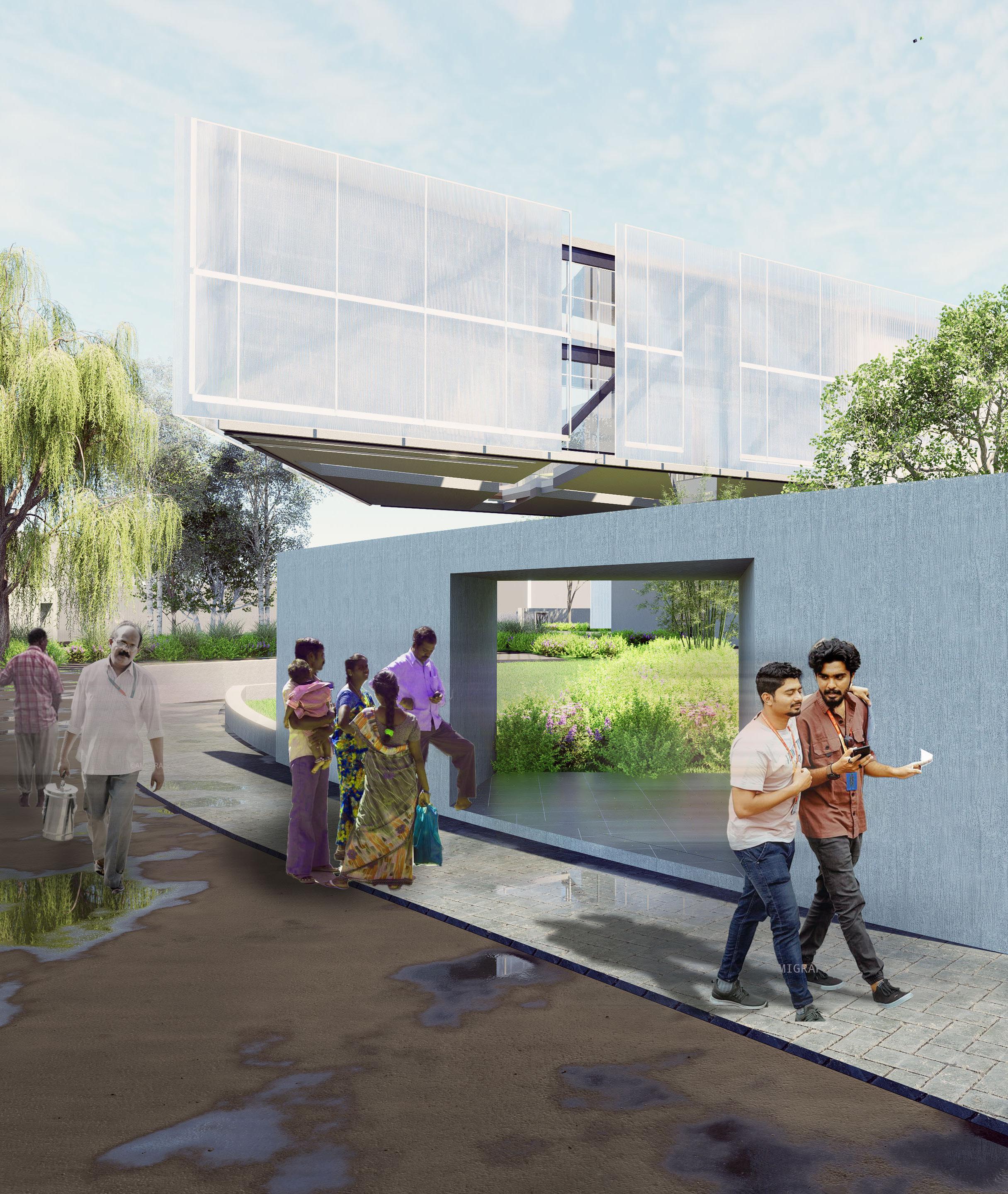
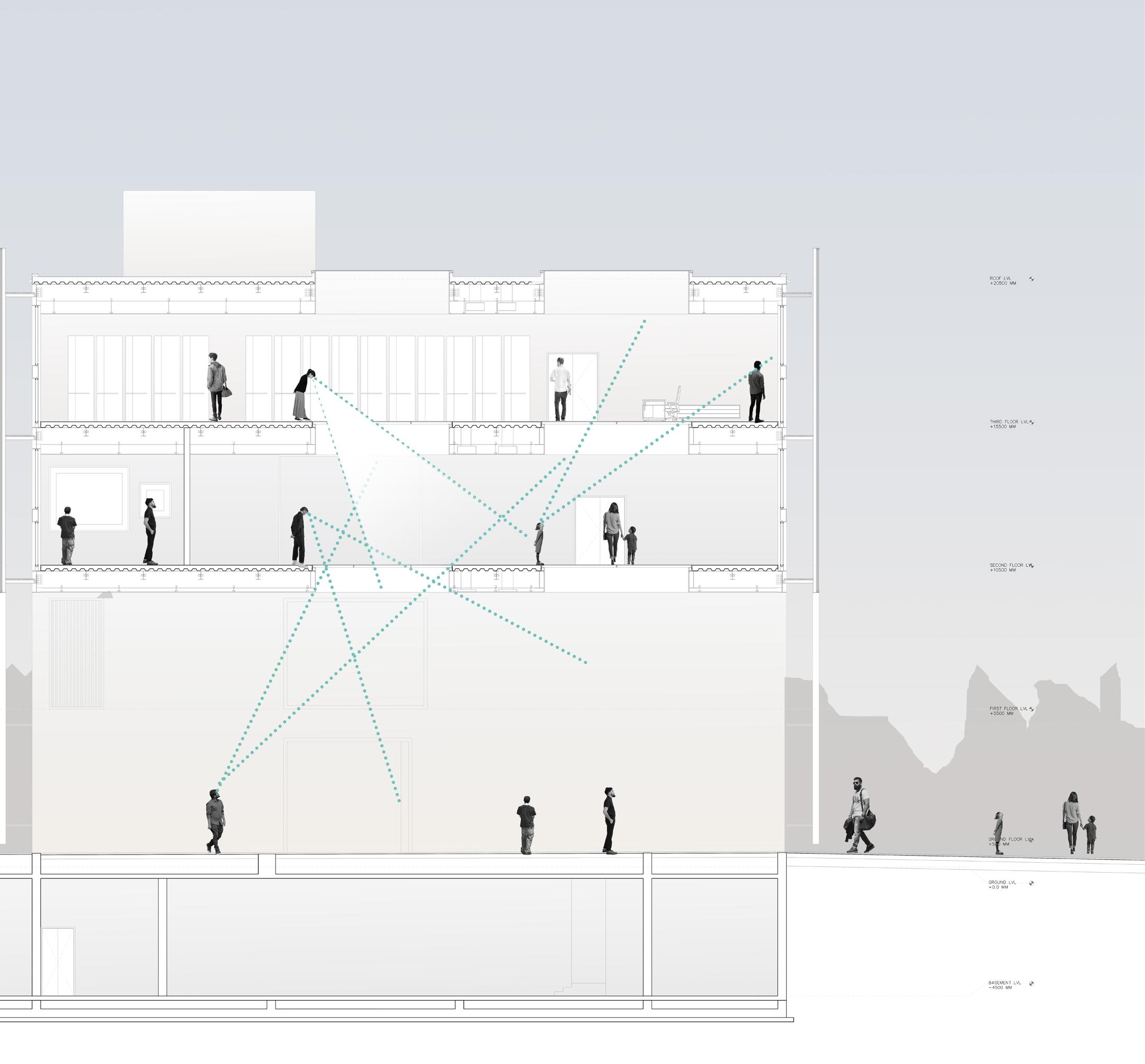
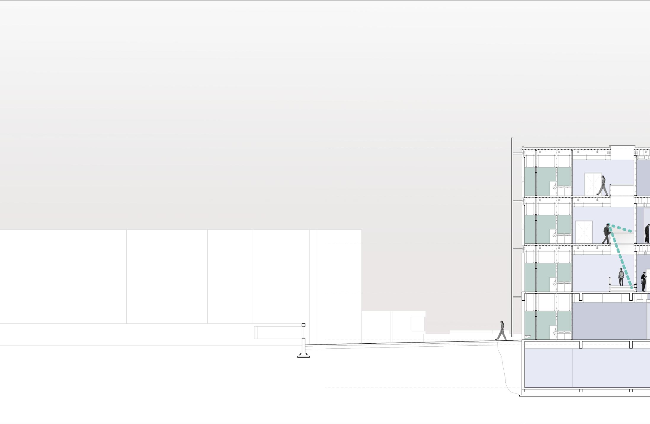
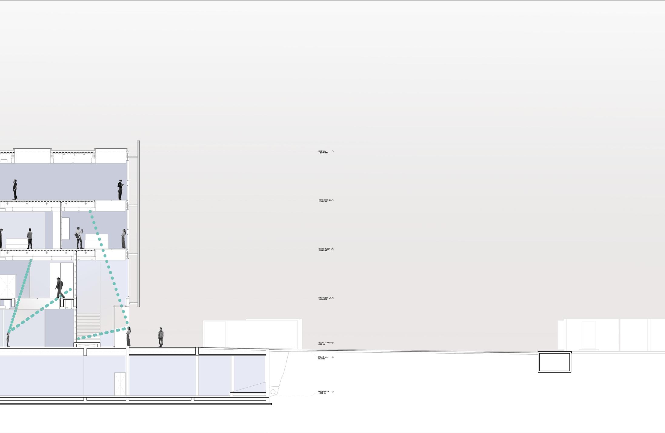
The project seeks to propose a design that bears traces of becomings of the city and the structure. This is achieved by employing urban artifacts and projecting indexical lines and traces onto the proposed structure, puncturing its form to facilitate a dynamic interaction between the institutional structure and its urban context, embodying a rhizomatic structure of continual multiple becomings.
5
N
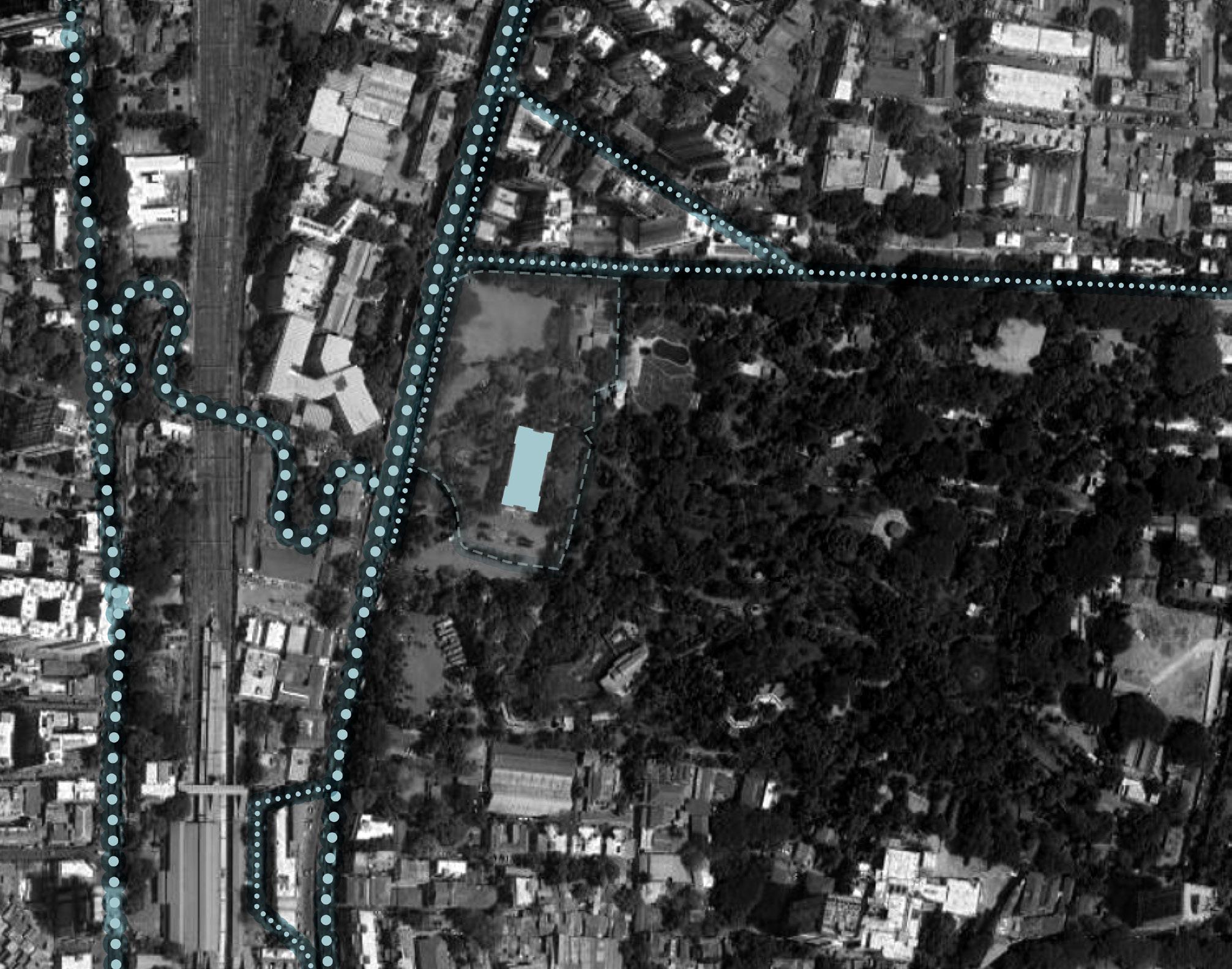
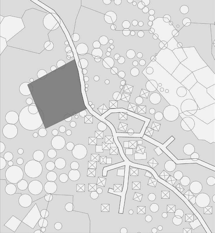
Above: Neighbourhood Map
1 Land Designated by the 2014 Competition Organisers for the North Wing Extension
2 Heritage Museum Structure
3 ES Patanwala Marg
4 Residential Zone
5 Eastern Express Highway
6 Byculla Suburban Railway Station
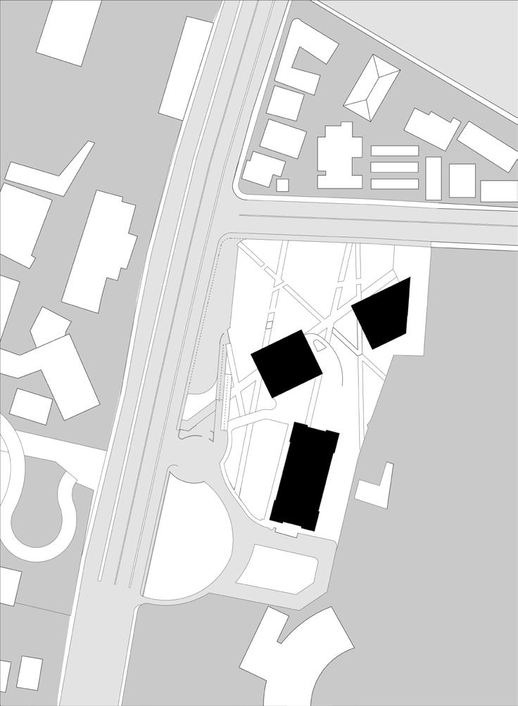
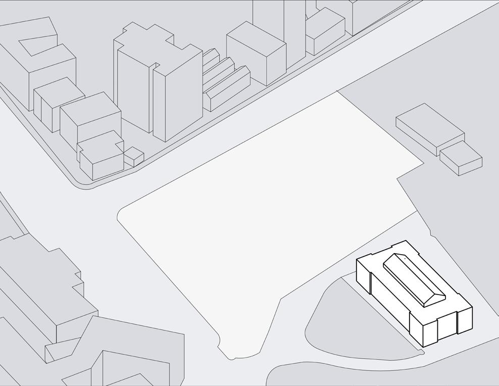
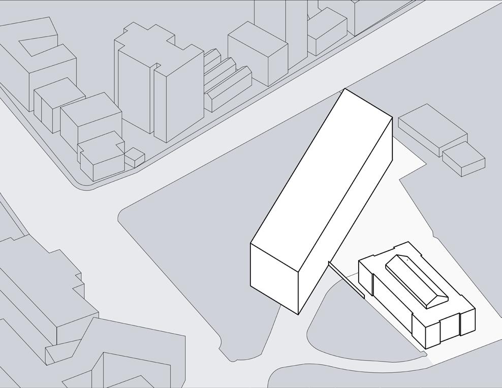
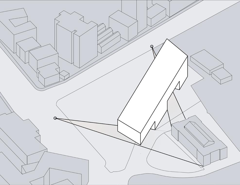
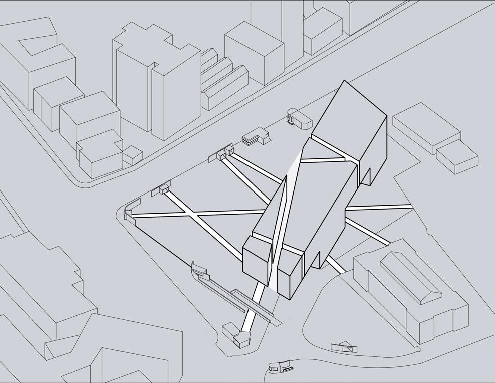
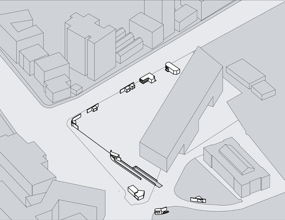
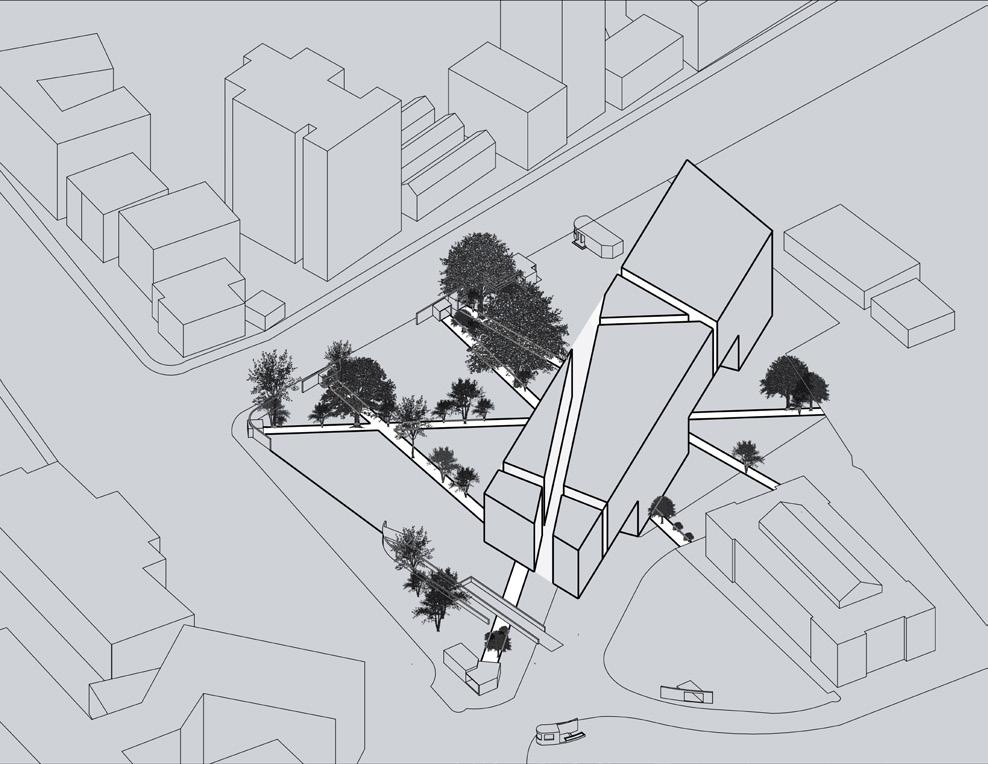
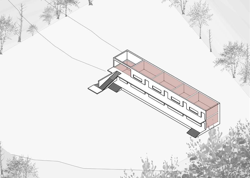
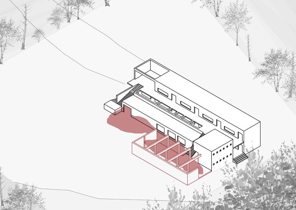
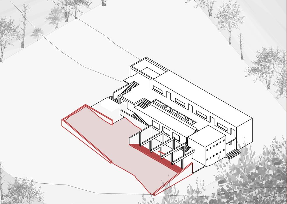
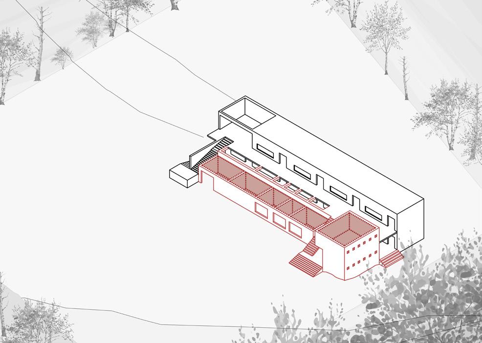
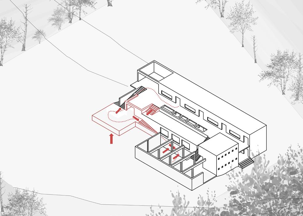
Right : Concept Diagrams
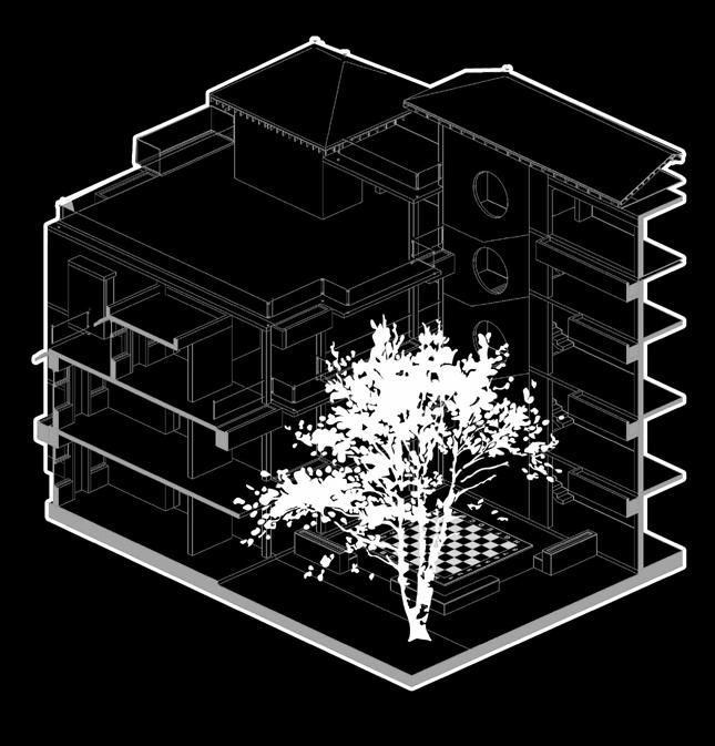
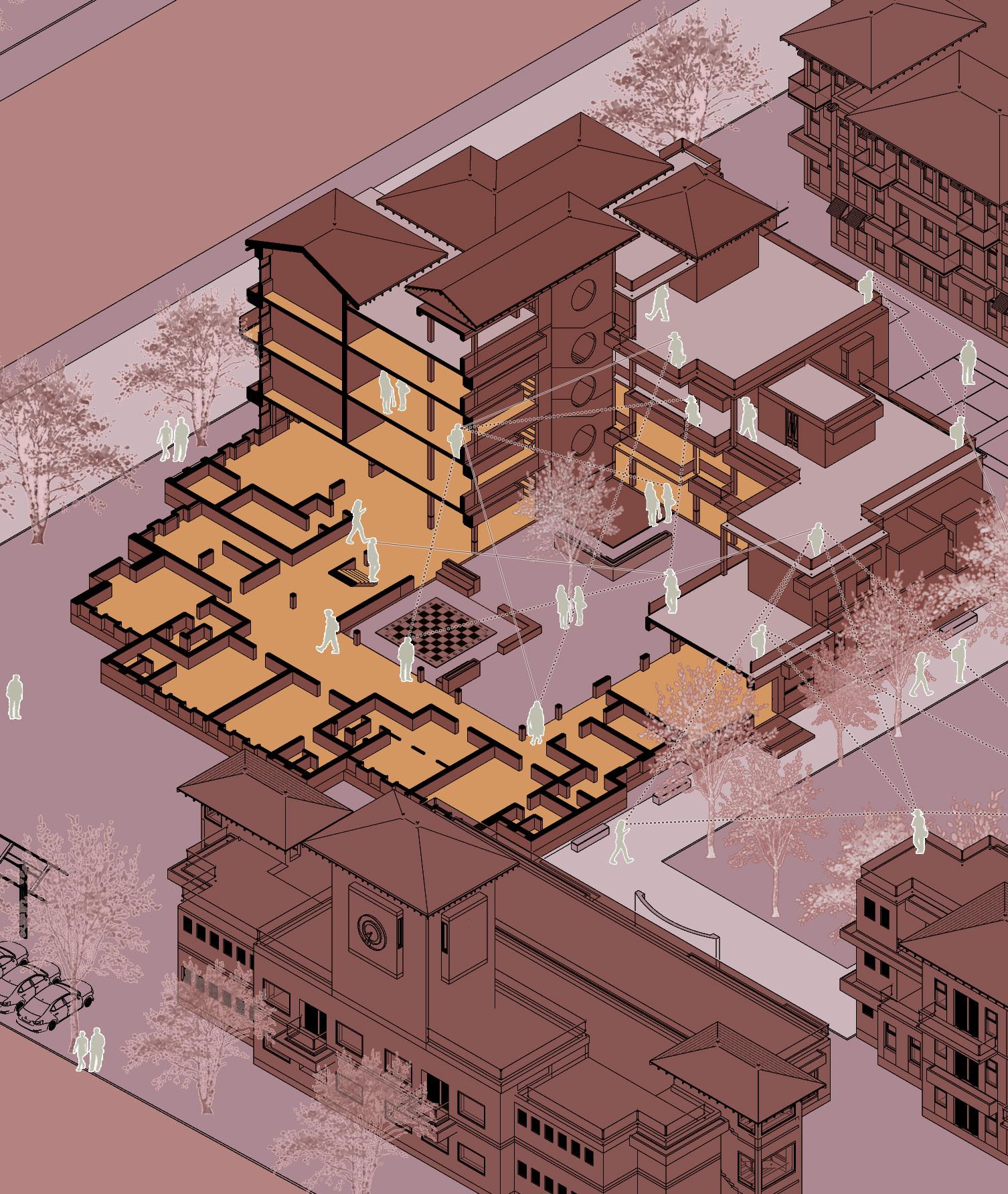
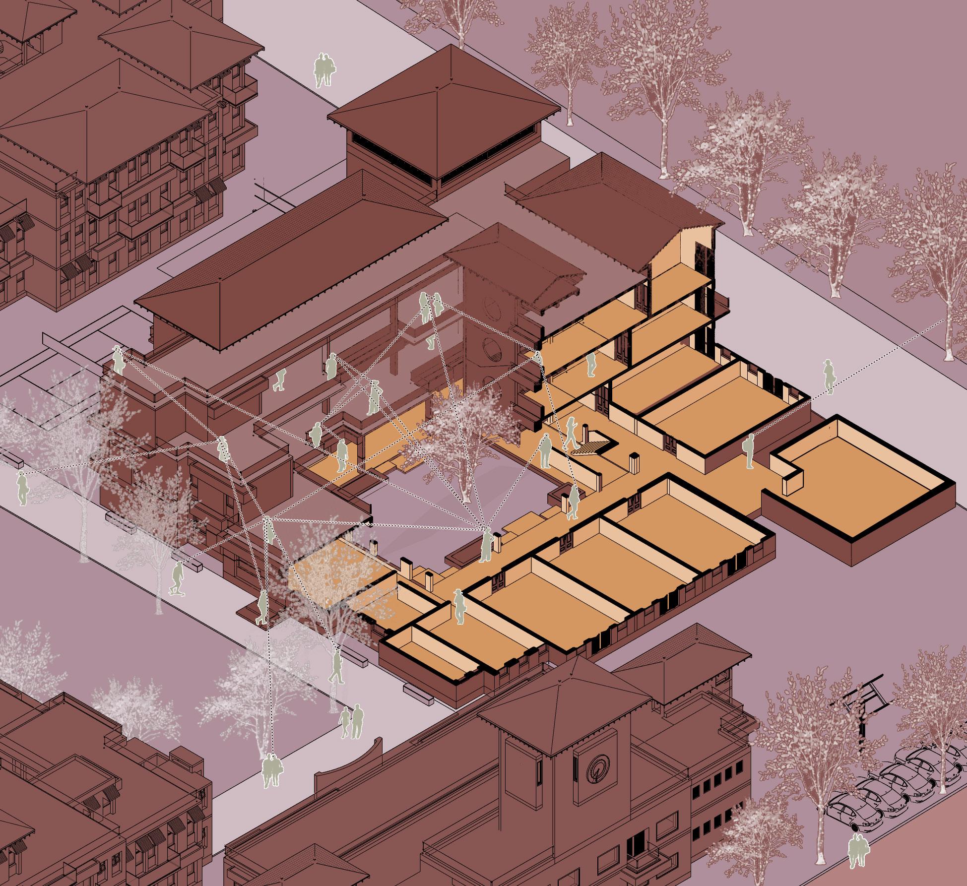
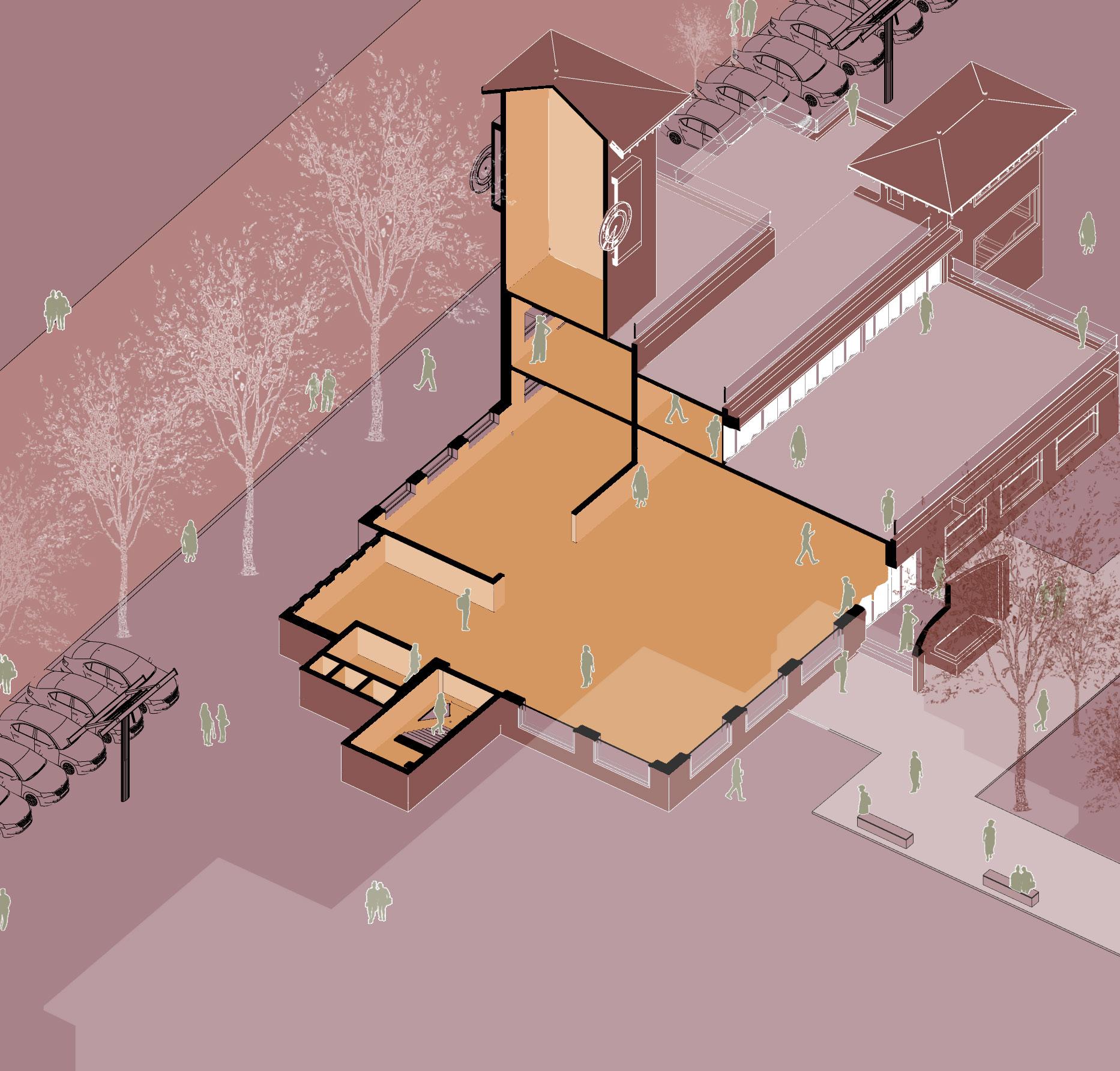
2 The design features a cuboidal form oriented along the north-south axis, leaving an open area to the north to serve as a plaza for the city.
3 Voids are introduced within the cuboidal forms to preserve views of the heritage structure, creating porous and adaptable spaces around the main structure.
4 “The city as a built form is a set of stable objects, or urban artifacts, in which the relationship between the parts is more significant than the parts themselves.“- Aldo Rossi ’Architecture of the City’ The design proposes seven urban artifacts embedded around the site, embodying Rossi’s conceptual framework.
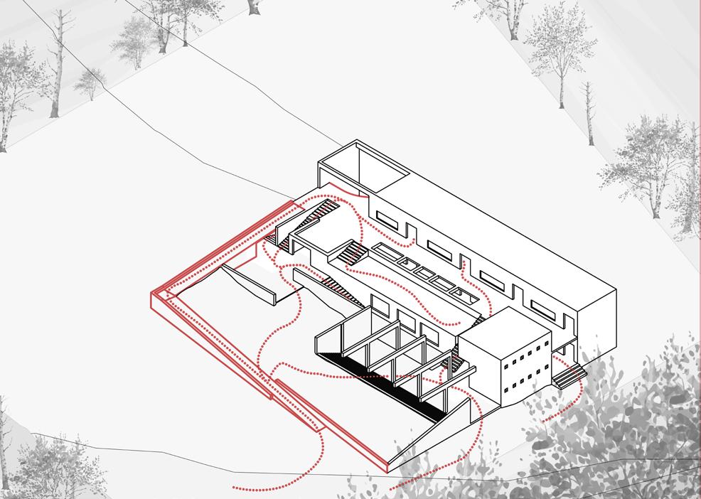
5 Indexical lines emanating from these urban artifacts are projected onto the site, influencing both the facade and floors of the structure. These lines manifest as openings in the facade and glass flooring, serving as the locus of these spatial relationships.
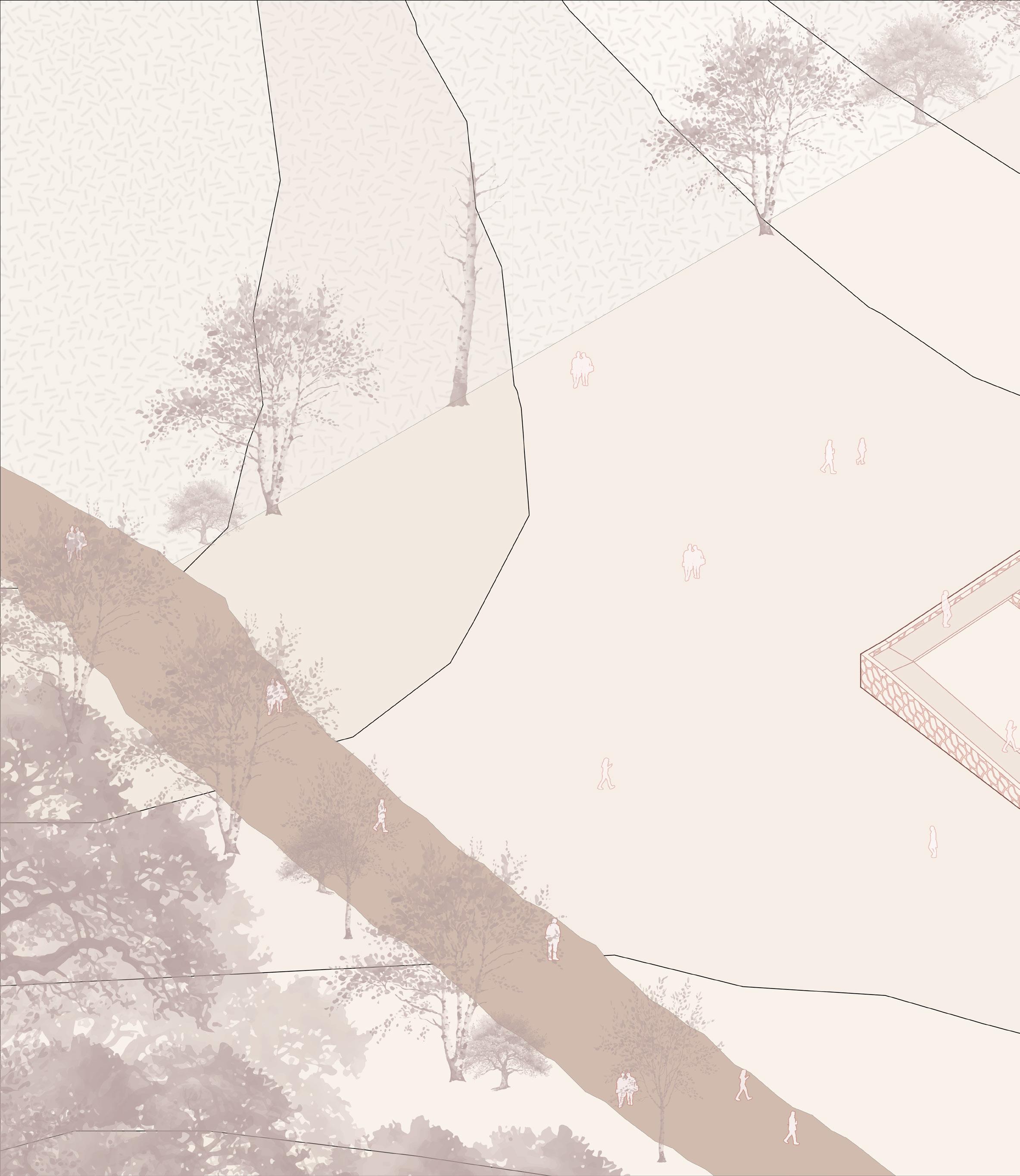
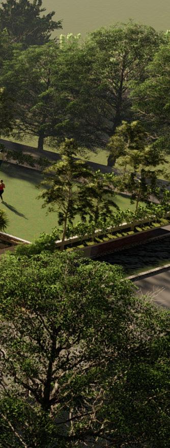
6 In the plaza located north of the Museum, these indexical lines define the landscaped areas incorporating plants and trees. These unpaved sections of the site, marked by these indexical lines, are left open to the dynamic interventions of local inhabitants over time. This seeks to harmonize the fluid, socially determined space with the traditional formality of the city plaza, fostering an environment that respects both historical continuity and contemporary social practices.
6
1 2 3 4 4 5 6
1
4 2
3 5 6
7
8 2 3 5 5 5 5 5 6 7 8 8 9 1 0 1 1 1 2 1 3 1 4
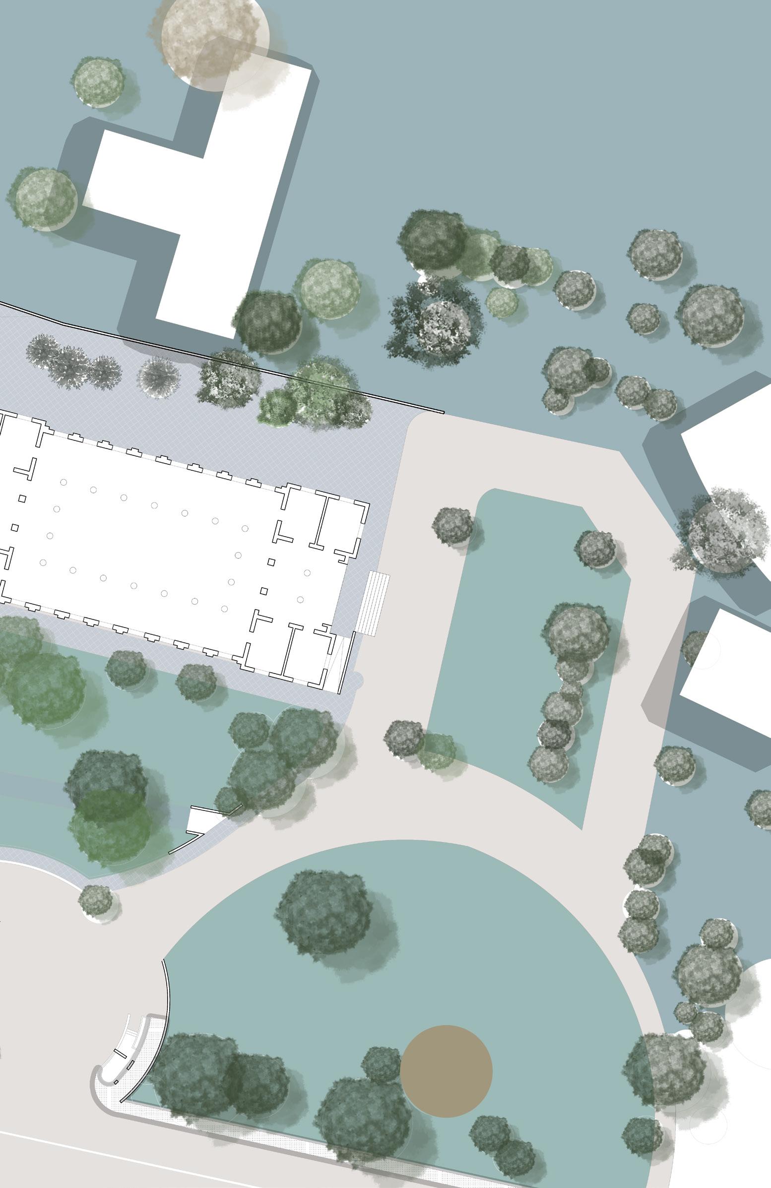
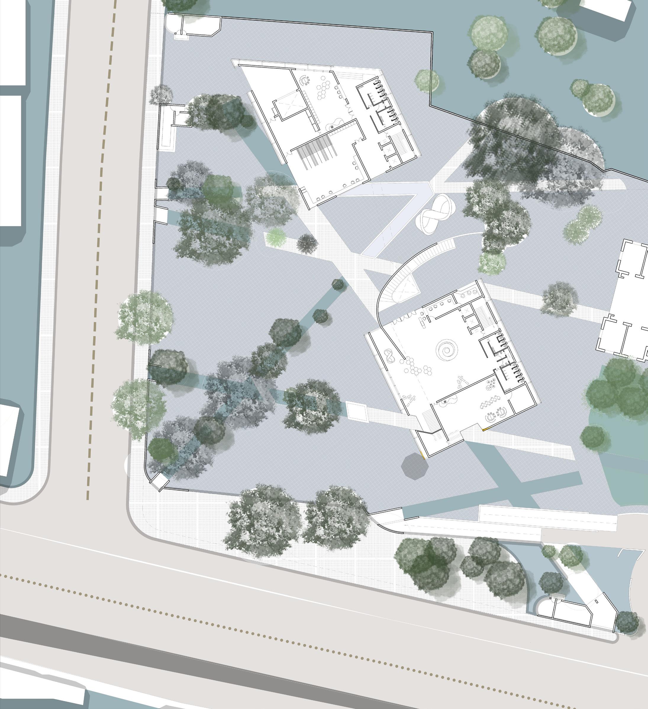
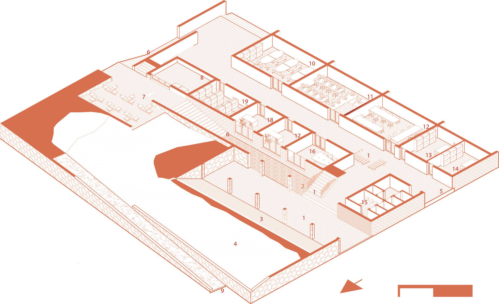
Site Plan:
Vehicular entry to the Site
Way to Basement Parking
Service Site Entry
Entry to Heritage Museum Structure
Urban Artifacts
Exit from Heritage Museum Structure
Entry to North Wing
Proposed North Wing Extension
Entry into North Wing Extension
9
3
4
5
6
7Staff
8
9
10
11 Western
12 Canteen 13 Security Cabin 14 Eastern Express Highway Flyover N 1 4 5 1 3
1
2
Central Void
Void
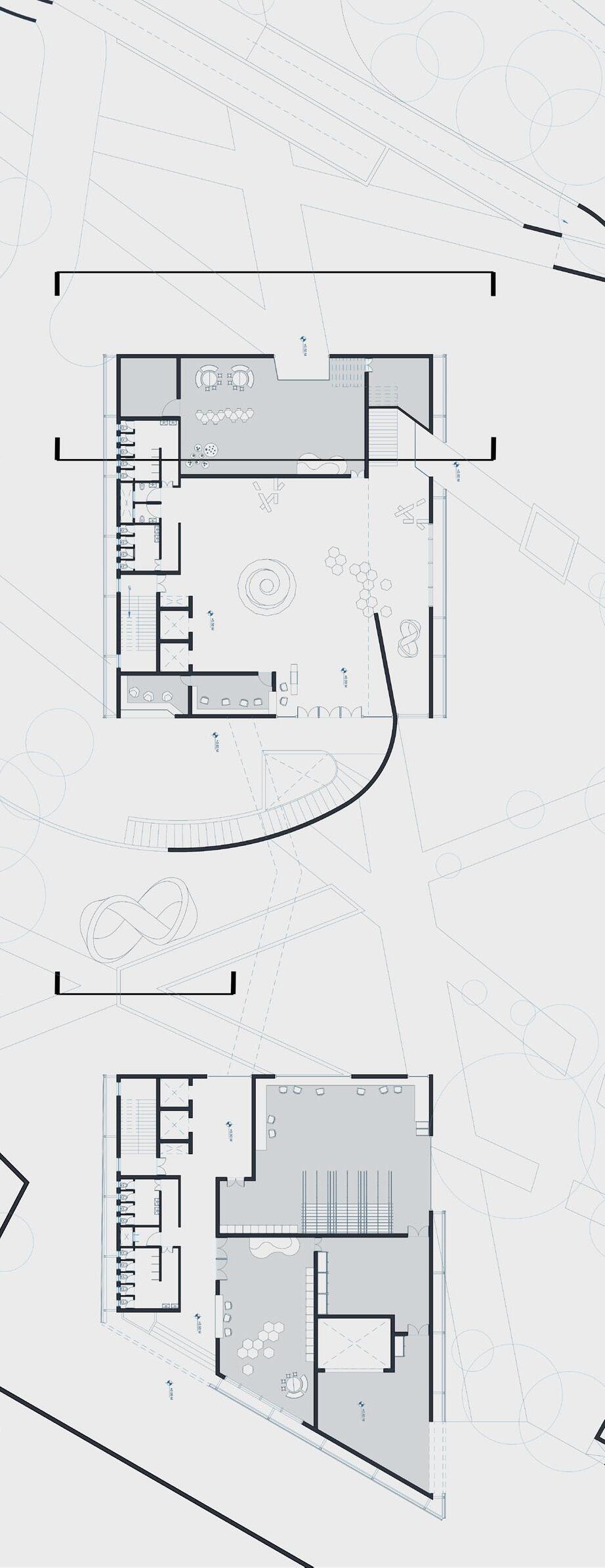
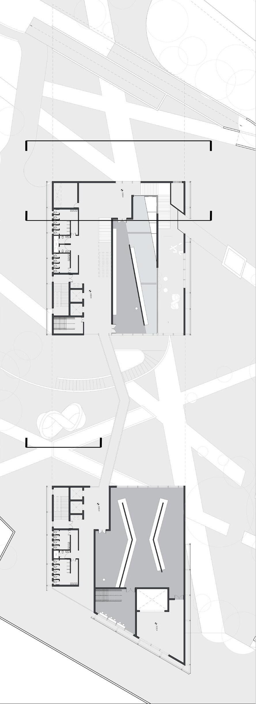
10 C C’ B B’ A A’ Ground Floorplan N 1 2 3 4 5 6 7 8 9 1 0 1 1 1 1 1 0 8 9 1 0 0M 5M 10M 20M
Ground Floorplan:
1 Museum Entrance Foyer Space
2 Stairs to First Floor
3 Children’s Museum
4 Ticketing and Security Cabins
5 Staff Entry
6 Staff Locker Room
7 Artifact Packing /Unpacking Room
4 Museum Library and Archives 5 Low Voltage Room 6 Museum Visitor Parking
11
10Ramp
7 Plenum 8 AC Plant Room 9 Ramp to Basement Parking
from Basement Parking
9
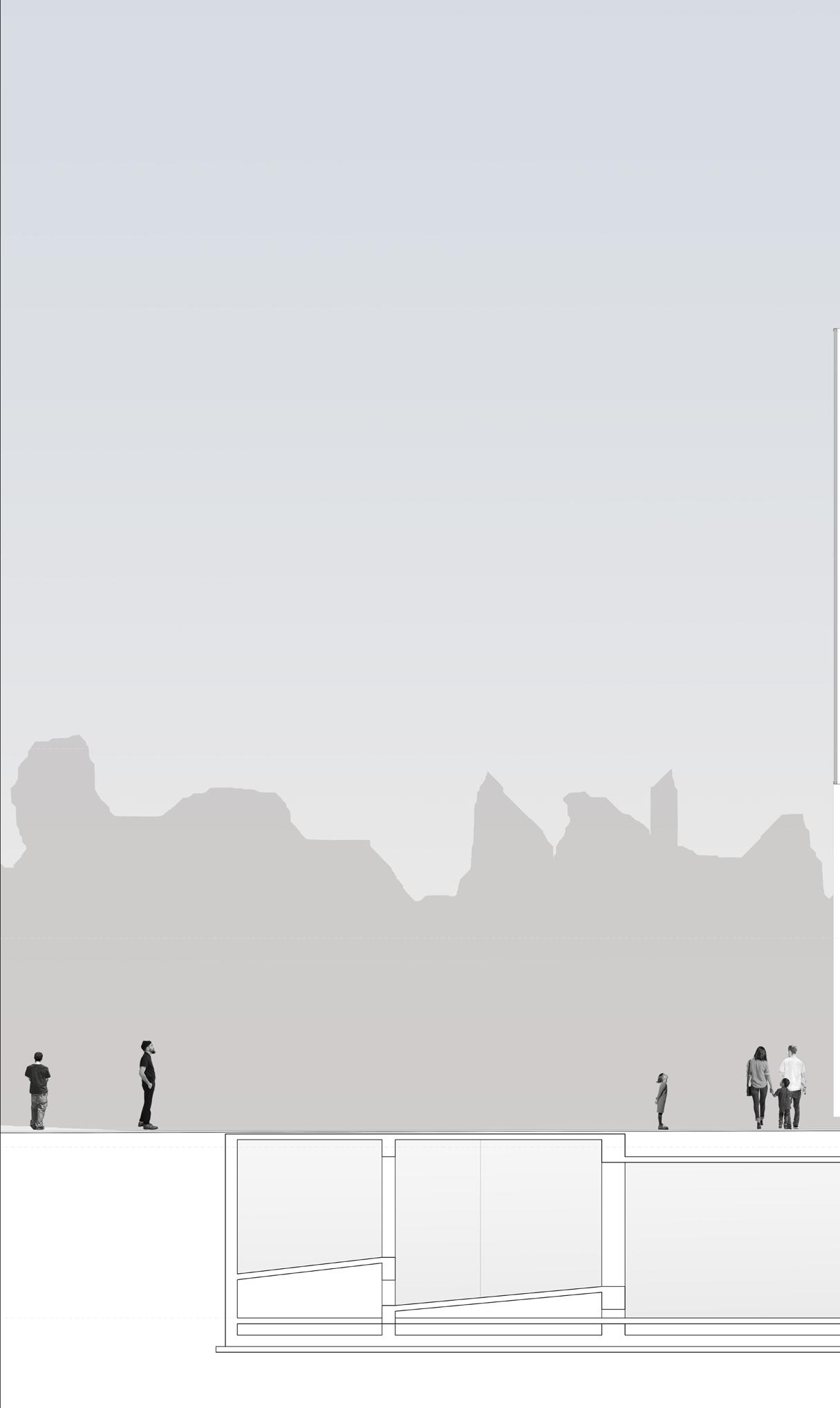
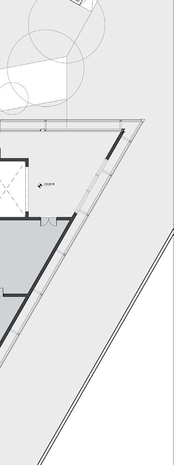
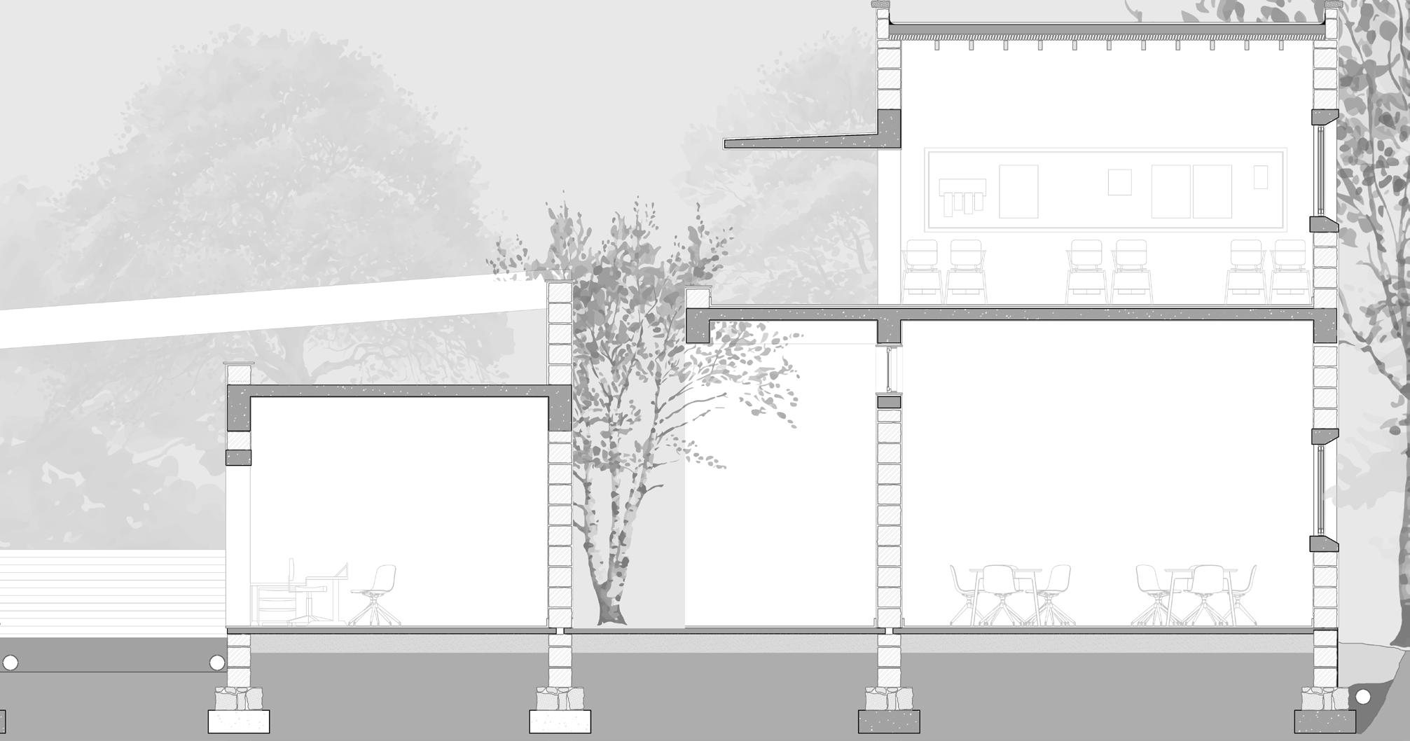
Conservation Room 10 Elevator and Fire Staircase 11 WCs Section AA’: 1 West Void 2 Film and Photography Gallery 3 Paintings Gallery Section AA’ 1 2 3 4 5 6 7
8 Loading/ Unloading Area
Artifact
12 C C’ B B’ A A’ 1 1 2 3 3 3 3 4 5 6 6 6 6 6 7 1 0 1 0 1 1 1 1
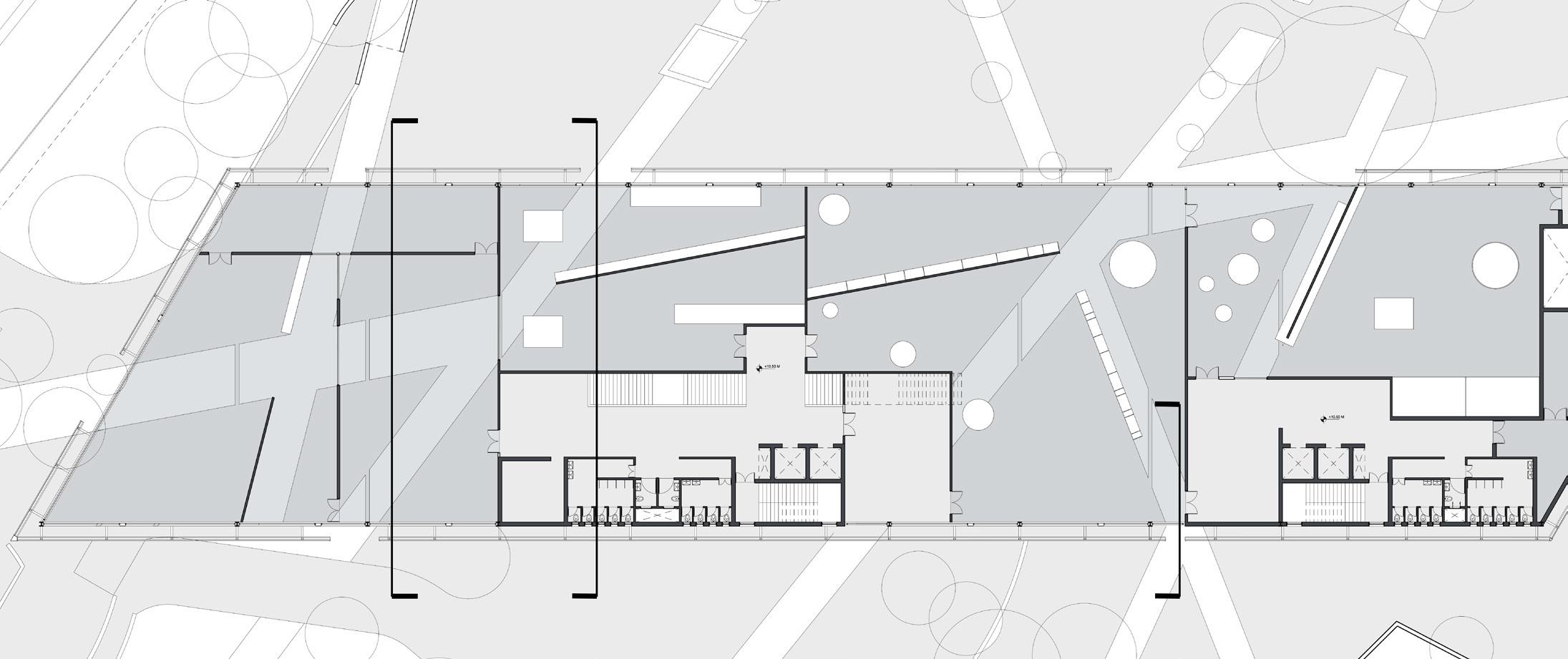
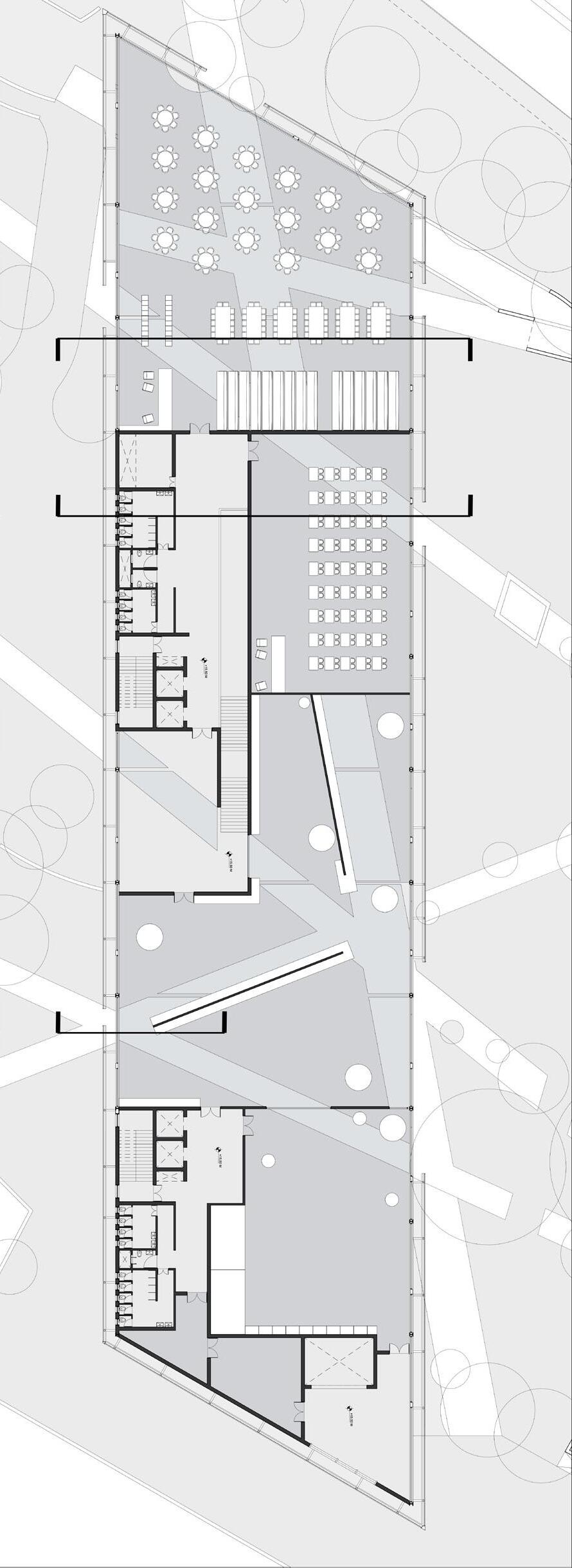
13 Second Floorplan Section BB’ Second Floorplan: 1 Architecture and Design Gallery 2 Textile Gallery 3 Temporary Gallery 4 Film and Photography Gallery 5 Painting Gallery 6 Prints Gallery 7 Staff Storage 8 Staff Foyer 9 Janitor’s Room 10 Elevators and Staircase 11 WCs Section BB’: 1 Children’s Museum 2 Stairs to First Floor 3 Gallery Foyer 4 Mumbai Gallery 5 Textile Gallery 6 WC 7 Workshop 8 Visitor Basement Parking 9 Ramp to and from Ground Level N 2 4 5 5 7 8 8 9 0M 5M 10M 20M
14 First Floorplan: 1 Foyer to Gallery 2 Mumbai Gallery 3 Bridge acroos the Central Void 4 Mumbai Creative Gallery 5 Conservation Room 6 Staff Foyer 7 AHU Room 8 Stair to Second Floor 9 Artifact Storage 10 Elevators and Stairs 11 WCs First Floorplan N 0M 5M 10M 20M 1 2 3 4 5 6 7 8 9 1 0 1 0 1 1 1 1
Floorplan
Third Floorplan: 1 Stair from Second Floor
2 Viewing Deck 3 Special Exhibitions Gallery 4 Temporary Gallery 5 Janitor’s Room 6 Staff Foyer
AHU Room 8 Workshop
Museum Library and Archives 10 Elevators and Stair 11 WCs
15
N 0M 5M 10M 20M 1 2 3 4 5 6 7 8 9 1 0 1 0 1 1 1 1
7
9
Third
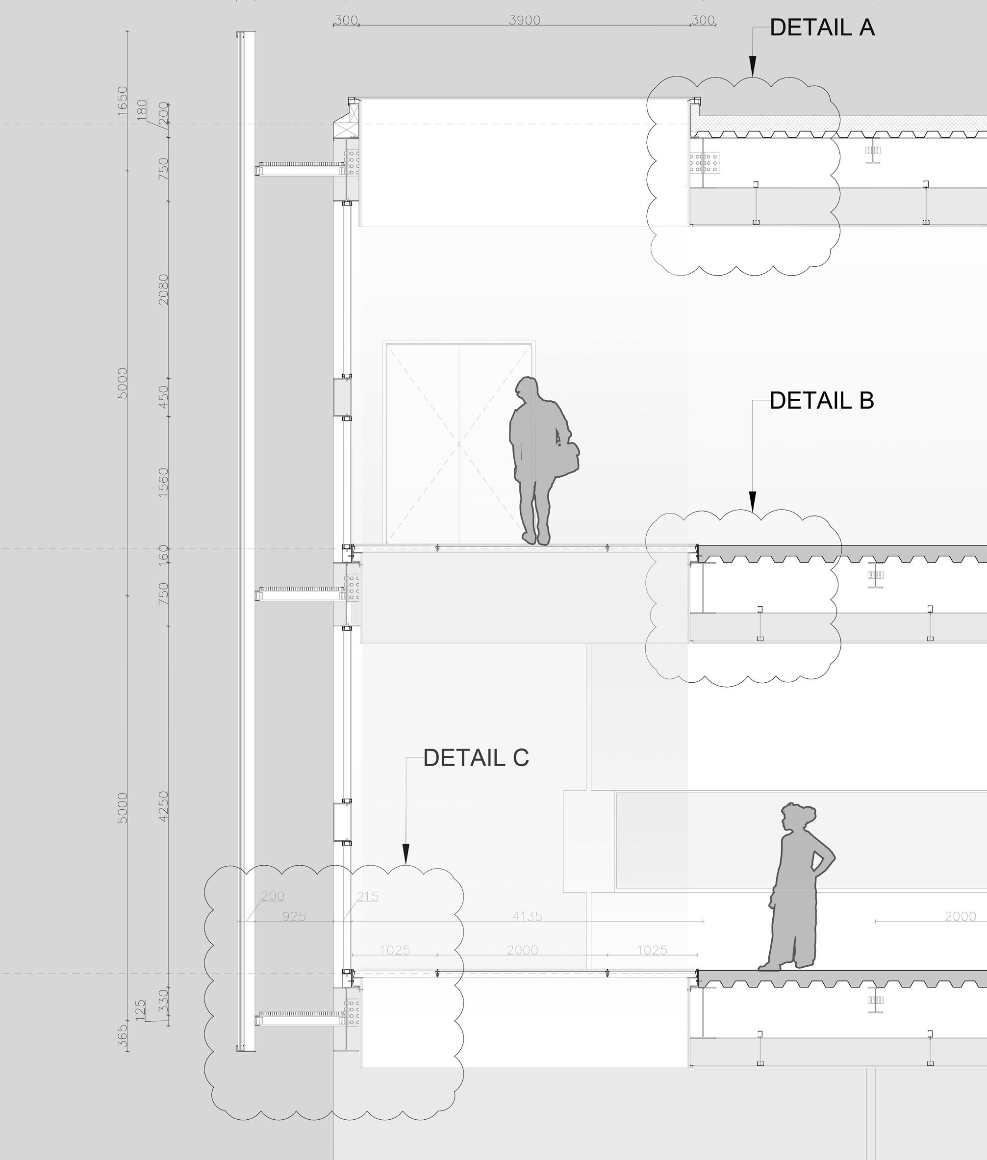
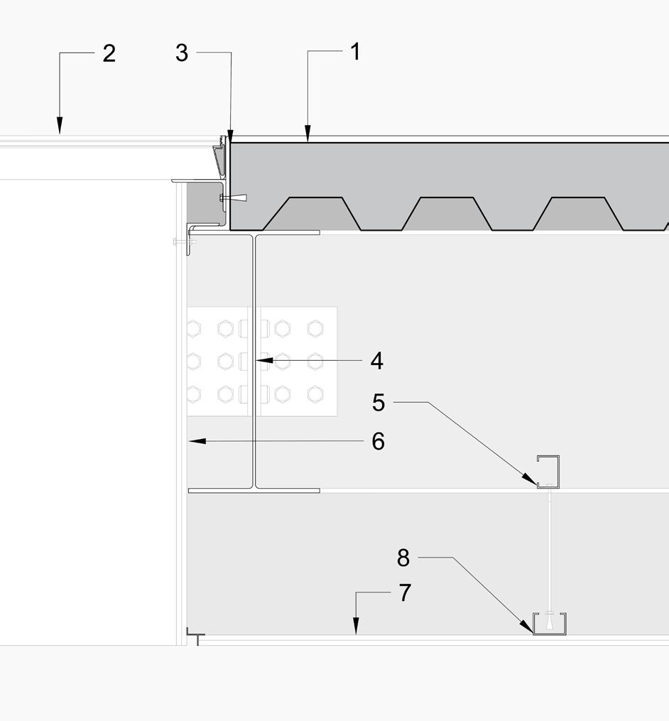
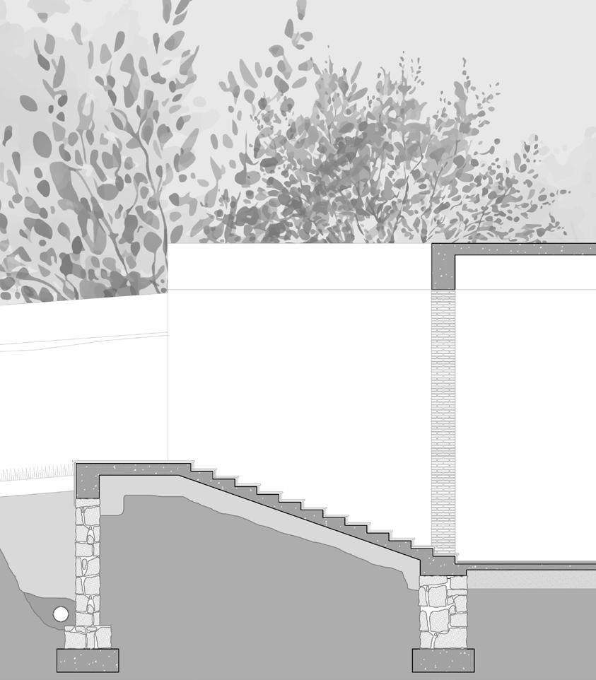
16 Wall Section CC’
Detail
Detail C Detail B
A
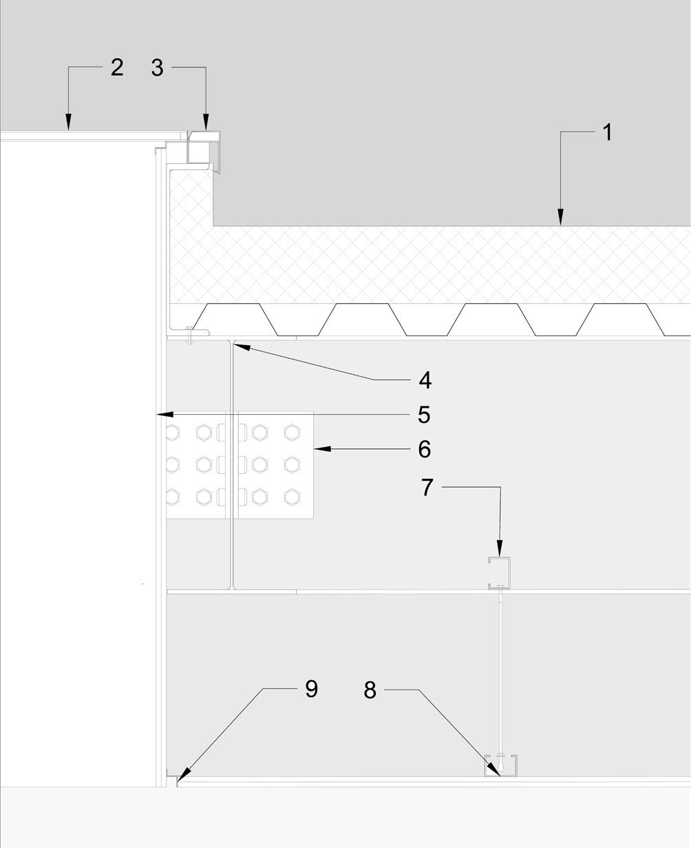
Detail A:
1. Polyester Water proof layer
180MM XPS Foam
75MM Trapezoidal metal sheeting
Supported by ISWB300, 2000MM C/C
2. 2X 6 MM Toughened Glass + 40MM cavity
3. Steel Flashing
4. 2Layers of 12MM Thk Plaster Board
5. ISHB 600 Steel I-Section Beam
6. 250X 175MM Angle Cleat Connection
7. 50X75 MM Steel C-Profile
8. 50X75 MM Steel C-Profile
9. Aluminum T-ceiling Profile
Detail B:
1. Structural Glass flooring Panel
2. 200MM Depth Reinforced Cement
Composite floor Slab
3. ISA 200100 Steel L-Section
4. ISHB 600 Steel I-Section Beam
5. ISLC 75 Steel C-Section
6. 2Layers of 12MM Thk Plaster Board
7. 2Layers of 12MM Thk Plaster Board
8. ISLC 75 Steel C-Section
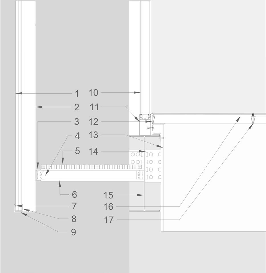
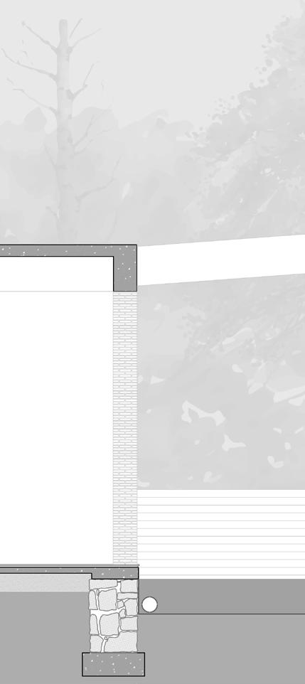
Detail C:
1 60MM THK Poly-Carbonate sheet
2 125/50MM Steel Rectangular Box Section
3 ISLC 150 C- Beam
4 125MM Angle Cleat Connection
5 40MM Thk Steel Grating
6 ISHB 150 I- Section
7 Backer Rod and Sealant
8 ISA 7575 Steel L-Section
9 ISA 200100 Steel L-Section
10 2X 25 MM Toughened Glass + 40MM cavity
11 160/115MM Steel Box Section(base for glazed façade unit)
12 100 MM Depth Perimeter Member
13 2 Layers of 12MM Thk Plaster Board
14 300MM Angle Cleat Connection
15 750MM Depth I- Section Beam
16 100 MM Depth Spacer Member
17 Structural Glass 25mm Thk Detail A
17
Detail B Detail C
20
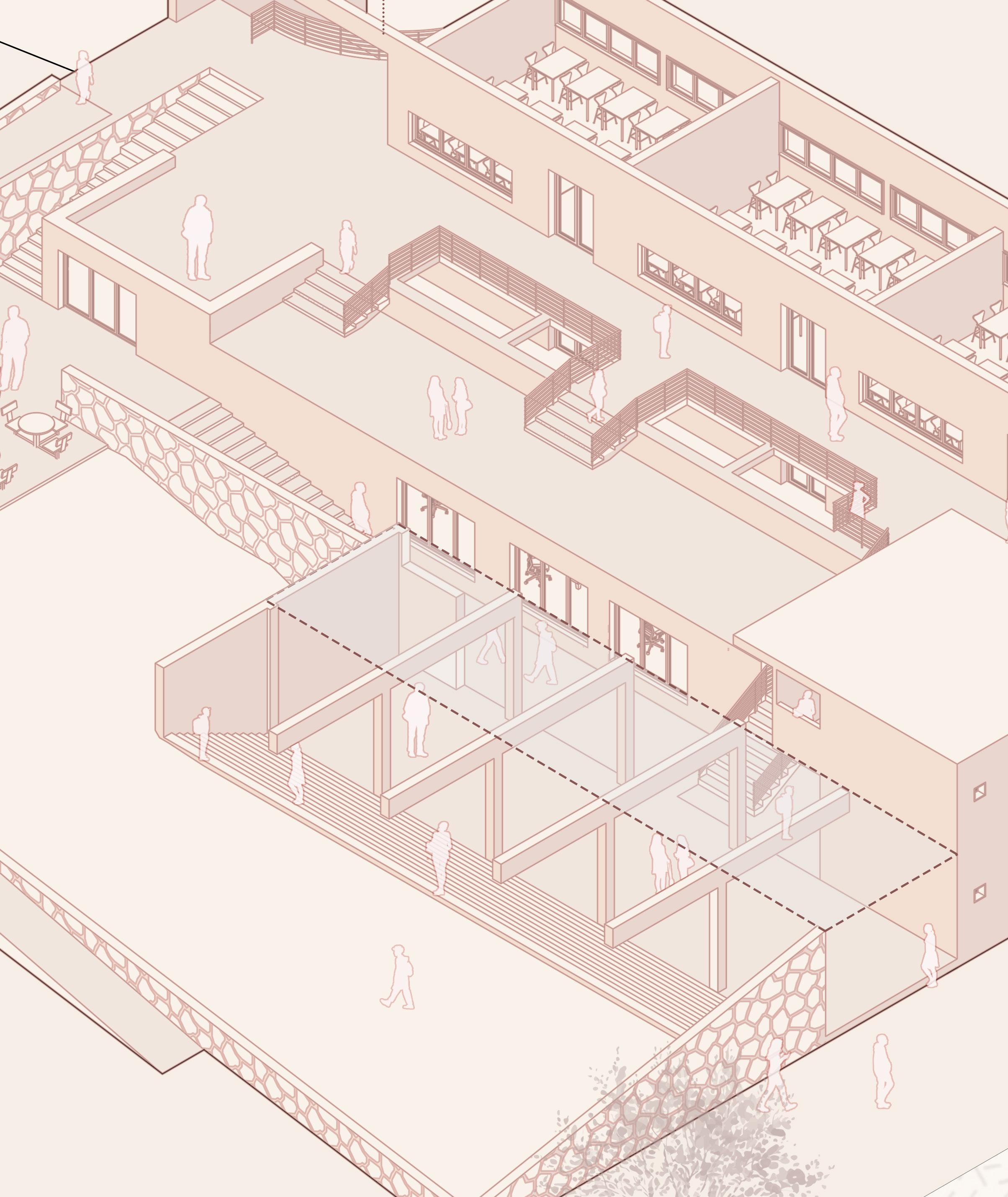
Community
A primary school and Community Centre Jambhe, Maharashtra
Location: Jambhe, Maharashta
Software used: Revit, AutoCad, Illustrator, Photoshop
A tribal village of 378 households, Jambhe is 34 kilometers away from the town of Vikramgad, and subsequently 34 kilometers away from financial, social and public services like hospitals, schools, colleges et cetera.It was necessary to begin the design by acknowledging the necessities of the village community and provide a program of spaces which shelter these services; and provide the village with meaning, community and a sense of immunity.
21
N
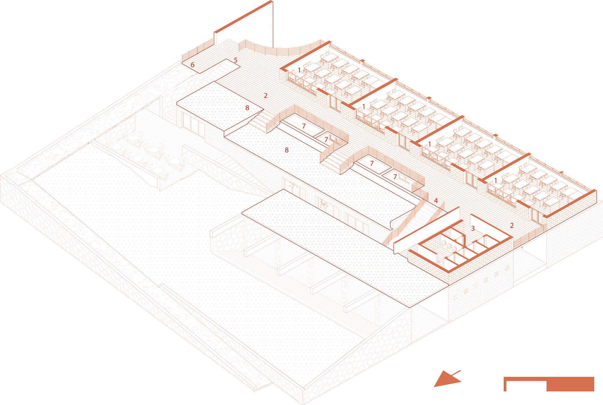
Floorplan:
1 Village Congregation Space
2 Gravelled Courtyard
3 Stairs to sloped lawn
4 Sloped lawn
5 Building Entrance (East)
6 Staircase leading to Canteen
7 Canteen (+1.5M)
8 Canteen Kitchen (+1.5M)
9 Ramp to First Floor
10 Library
The design approach consists in creating homogenous spaces of 3 categories and to allow for a permeable flow between them and the spaces with the village fabric.
Having courtyard spaces (2) -whose spaces act like a melting pot between blocks that-makes the structure maleable in its functional abilities; being able to service a panchayat or rendering itself capable to hosting a vaccination drive, et cetera.
22
11
12
13 Principal’s office 14 Headmaster’s office 15 Toilet 16 Medical room 17 Counselling room 18
19
Computer Lab
Staff room
Admin Room
Storage Rooms Ground
Placement of school with amenity spaces (labs, library, offices) on the Ground and Classrooms on the First floor.
Addition of Congregation space which can shelter the activities of the community (festivals, marriages, panchayats)
Lifting the landscape to access the classrooms thereby giving the community space malleability in its capacity..
Addition of amenities spaces (Counselling, Medical rooms ) in such a way as to be accessed independent of the school.
Elevating the Canteen so as to be accessible to the Academic and the Community spaces.
Thus creating a porous structure without creating boundaries with the village it is meant to serve.
23
24
First Floorplan:
1 Classroom
2 Corridor
3 Toilet
4 Staircase leading down to community space
5 Staircase leading down to Canteen
6 Ramp leading down to Ground
7 Light wells down to Ground Floor
8 Spaces for future additional development
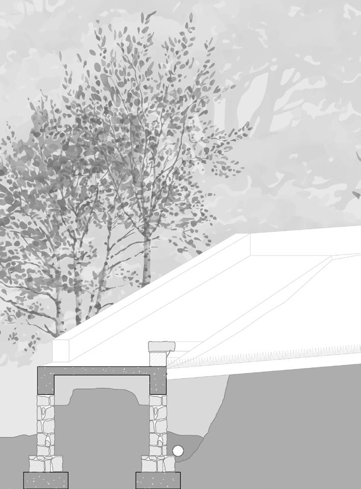
Section AA’:
1 25MM Cement Concrete
75MM Lime Concrete
250 MM Fine Sand Bedding
2 300MM Thk Red Laterite Stone Wall
12MM Thk Internal Plaster
3 25MM Cement Concrete 150MM Thk RCC
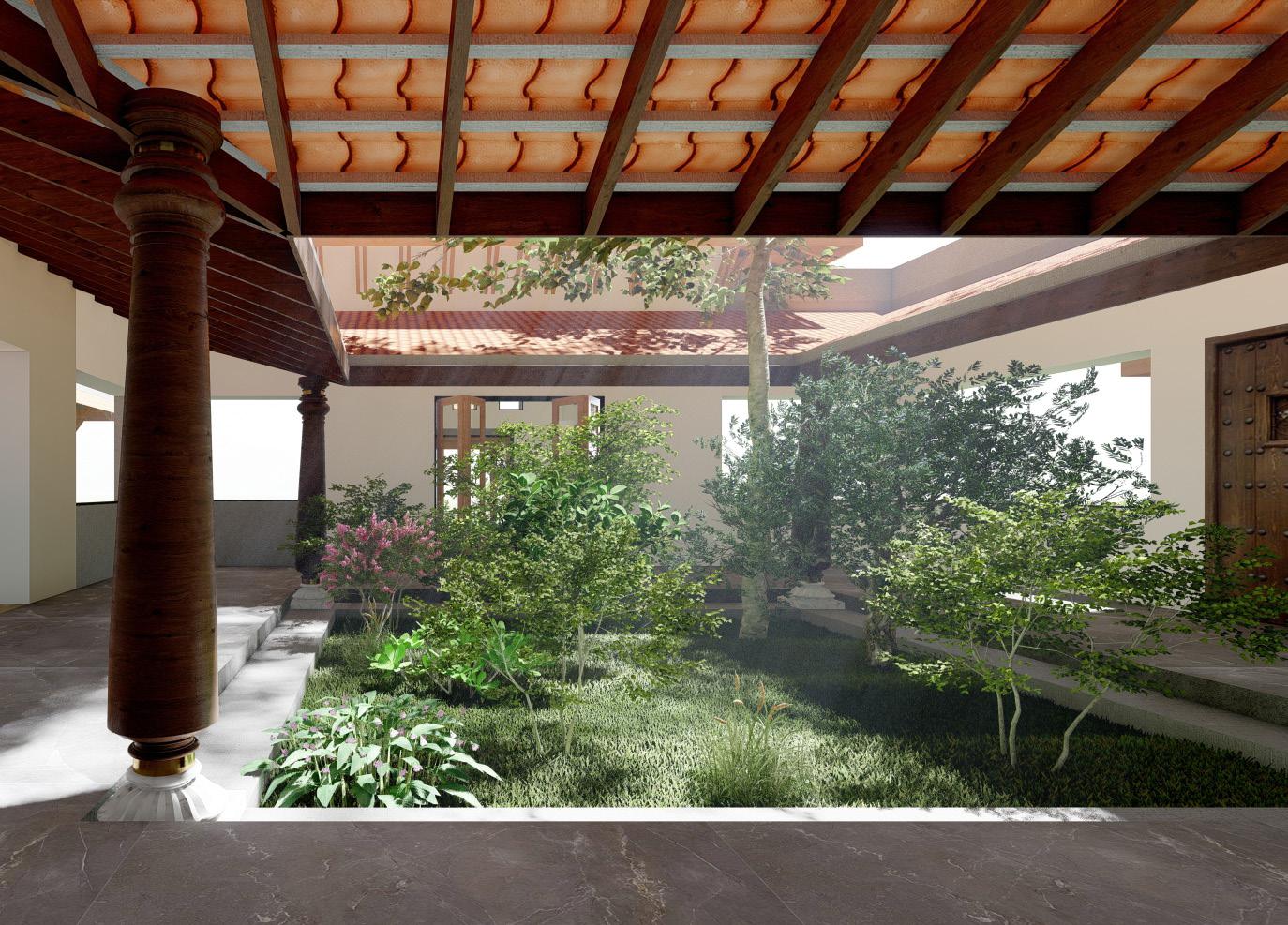
4 Madras Terrace Roof:
Wooden Rafter 50/120MM 450mm c/c
Bricks laid with Lime Mortar (Diagonally inclined in Plan)
Lime Concrete - 1 part Lime 3 parts Brick Bats
Terracota Tiles laid with Lime Mortar
3 Coats of Plaster
25
N 2 1 3 4 UP UP UP
Gandhianism
Location: Sabarmati, Gujarat
Contribution: Design and planning studies, CAD plans and sections, Sketchup 3D Study Models.
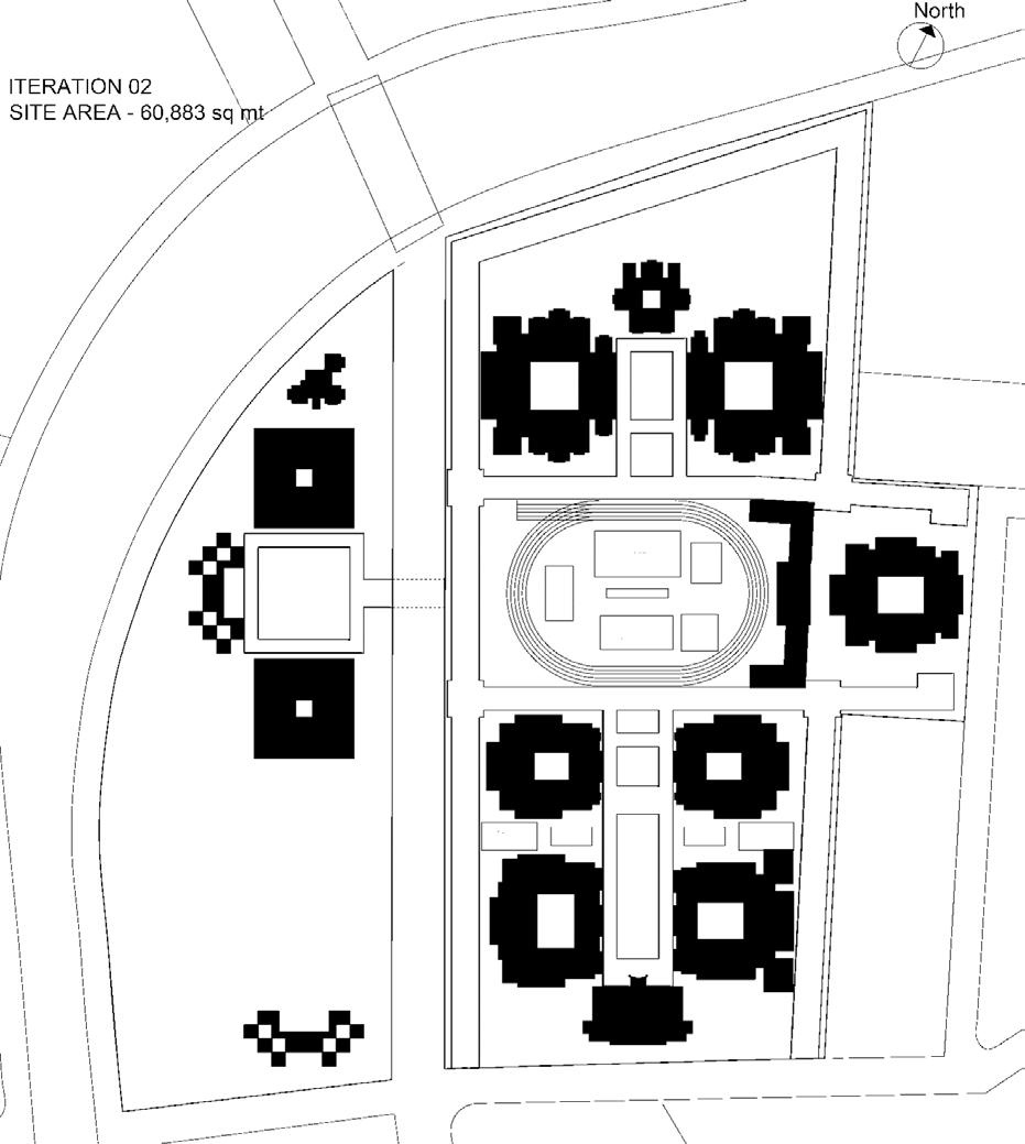
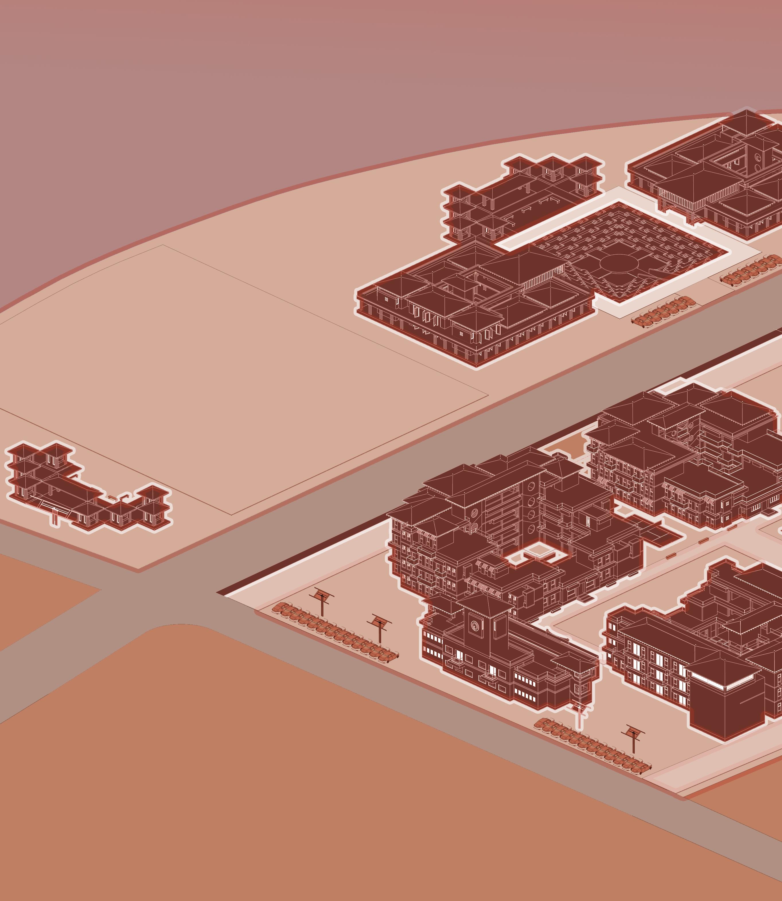
The Gandhi Ashram Shaikshanik Sankul is an integral part of the larger Mahatma Gandhi Sabarmati Ashram, located near Ahmedabad. This project envisioned the creation of an educational hub near Mahatma Gandhi’s Sabarmati Ashram, encompassing schools, hostels, college buildings, administrative buildings, and workshops.
An 18-meter-wide road bisects the planned area into two plots: the northeastern plot (20,600 sqm) and the southwestern plot (43,049 sqm), totaling 60,883 sqm. The design aligns with the philosophies of M.K. Gandhi and J. Krishnamurti, ensuring that the architectural approach reflects their principles. This project was undertaken as part of my internship at Footprints E.A.R.T.H.
29
N
Gandhi Aashram Shaikshanik Sankul (Education Hub)
1 2 3 4 1 2 1 3 1 5
1 Gandhi 3.O (Administrative Building) 2 Guest House 3 Heartisan Haath 4 Retreat and Skill Training Centre 5 Director’s Bungalow 6 Stree Adhyapan Mandir(PTC College) 7 Lady Montessery Nursery 8 Vinay Mandir (Girls Secondary School) 9 Aashram Shala (Primary School) 10 Amphitheatre 11 Sports Ground 12 Vinay Mandir (320 bed Girls Hostel) 13 Bharateshwari Hostel (200 bed ) 14 Aashram Shala Hostel (160 bed) 15 Dining and Kitchen 5 6 7 8 9 1 0 1 1 1 2 1 4
32 2 2 2 2 2 2 2 Bharateshwari
1 3 6 5
Hostel
33 Third Floorplan 1 2 2 2 2 2 2 2 2 2 2 2 2 2 2 2 2 2 2 2 2 6 2 2 4 2 2 2 2 2 2 4 2 2 2 2 2 2 2 2 2 2 2 4 4 4 4 3 5 7 Ground Floorplan Second Floorplan First Floorplan
This is a 160 capacity Hostel with the purpose of housing the Aashram Shala students.
1 Waiting and Reception 2
Bharateshwari Hostel:
This is a 200 capacity Hostel with the purpose of housing the Aashram Shala students.
1 Library
2 5 Sharing Rooms 3 Waiting and Reception 4 Gruhmata (Warden)room 5 Medical room
6 Guest Room 7 Laundry Room
34
Aashram Shala Hostel:
Hostel Room 3 Gruhmata room 4 Toilet 5 Medical Room 6 Guest Room
1 2 2 2 2 2 2 2 4 3 6
Aashram Shala Hostel
Floorplan
Floorplan
Floorplan
35 2 2 1 5 6 6 6 6 6 3 3 3 2 2 2 2 2 2 2 2 2 2 2 2 2 2 2 4 4 4 4 4 4 2 2 2 2 2 2 2 2 2 2
Ground
Second
First
Dining and Kitchen Hall
36 1 2 3 4 5
37 Dining
Hall: 1 Dining Space 2 Kitchen 3 Toilets 4 Kitchen Staff Quaters 5 Overhead Water Tank Ground Floorplan First Floorplan 1 2 4 4 3 3 3 3 3 3
and Kitchen
38
Vidyamandir
A new wing for the BAPS Vidyamandir (school) at Nadiad.
Location: Nadiad, Gujarat
Contribution: Design and planning studies; CAD plans, sections and working drawings; Sketchup 3D Study Models and Site visits.
The project involved designing and producing working drawings for a new wing at the BAPS School in Nadiad. This addition was designed to accommodate six new classrooms and office spaces.
This project was undertaken as part of my internship at Footprints E.A.R.T.H.
39
40 1 2 3 4 5 6 7 8 9 10 11 12 13 14 15 LEVEL +0.00 LEVEL +0.45 M LEVEL +0.45 M LEVEL +0.30 M LEVEL +0.45 M 16 16 16 16 16 16 KITCHEN BELOW LANDING +0.30 M CLASSROOM 1 6000 X 8000 CLASSROOM 2 6000 X 8000 CLASSROOM 3 6000 X 8000 CLASSROOM 4 6000 X 8000 OFFICE 1 3160 X 4630 OFFICE 2 3160 X 4630 INSIDE STORAGE +0.45 M A B C D E F G H J K L M 1 2 3 4 5 6 7 8 9 10 11 12 13 14 15 16 17 18 19 20 21 22 A B C D E F G H J K L M A8 A10 A15 A17 B6 D9 C12 C13 D16 B19 F23 G20 E13 E12 G5 F2 H1 H24 K23 K21 K14 K11 K4 K2 M3 L7 L15 M22 23 24 1 2 3 4 5 6 7 8 9 10 11 12 13 14 15 16 17 18 19 20 21 22 23 24 J5 J9 J16 J20 D1 Section AA’ Column Layout Plan
First Floor Civil Layout Plan Ground Floor Civil Layout Plan
41 1 2 3 4 5 6 7 8 9 10 11 12 13 14 15 LEVEL +0.00 LEVEL +0.45 M LEVEL +0.45 M LEVEL +0.30 M LEVEL +0.45 M 16 16 16 16 16 16 LANDING ROOM 2570 X 3520 CLASSROOM 1 6000 X 8000 CLASSROOM 2 6000 X 8000 CLASSROOM 3 6000 X 8000 CLASSROOM 4 6000 X 8000 OFFICE 1 3160 X 4630 OFFICE 2 3160 X 4630 1 2 3 4 5 6 7 8 9 10 11 12 13 14 15 16 16 16 16 16 16 LOWER LANDING ROOM 2570 X 3520 5M LVL CLASSROOM 5 6000 X 8000 CLASSROOM 6 6000 X 8000
42
Plan
Ground Floor Electric Layout
Drawings
This section consists of miscallaneous drawings done during my internship at Footprints E.A.R.T.H. including working drawings; layouts and Renders.
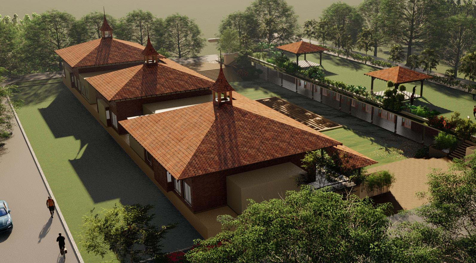
+Electrical Layout of Malanka Farmhouse
+Wall Section of Binori Aashiyana (Mixed use High-rise) +Renders of other projects done in Lumion
Switch Board Schedule of Malanka Farmhouse
43
First Floor Electric Layout Plan
44 W13 Sill 900 Lintel@+2100 W13 Sill 900 Lintel@+2100 W15 Sill 900 Lintel@+2100 W01 Sill@+900 Lintel@+2100 W01 Sill@+900 Lintel@+2100 D09 D06 D04 D05 D04
45 DUCT DUCT C-102,202,302,402,502, 602,702,802,902,1002, 1102,1202,1302,1402 900 684 Lintel @+2370 Sill @+900 W04 W04 Lintel @+2100 D01 D01 Lintel @+2100 Lintel @+2100 D02 D02 D02 D02 Lintel @+2100 D02 Lintel @+2100 D02 D02 D03 Lintel @+2100 D03 D03 Lintel @+2100 D03 D03 Lintel @+2100 Sill @+1200 Lintel @+2100 Sill @+1200 Lintel @+2100 Sill @+1200 V01 V01 V01 V01 V01 V01 Lintel @+2370 Sill @+SKIRTING W02 W02 Lintel @+2370 Sill @+SKIRTING W03 Lintel @+2370 Sill @+750 W03 W01 W01 Lintel @+2370 Sill @+750 W03
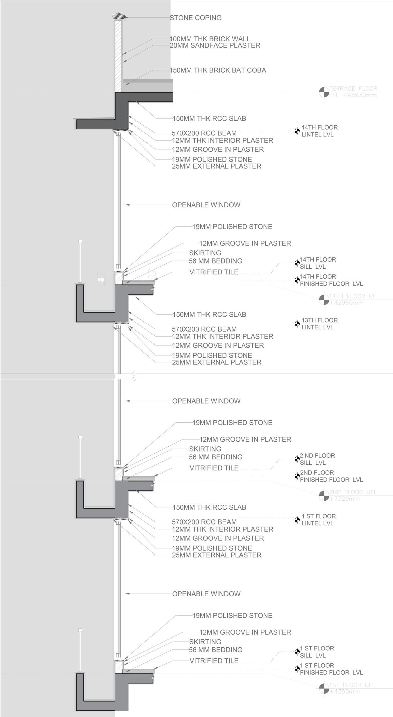
Wall
Section AA’ Binori Aashiyana (Mixed used High Rise Building)
46
47
SketchUp 3D and Render Of L-Option Bungalow of Ayodhya Plotting Sheme
48
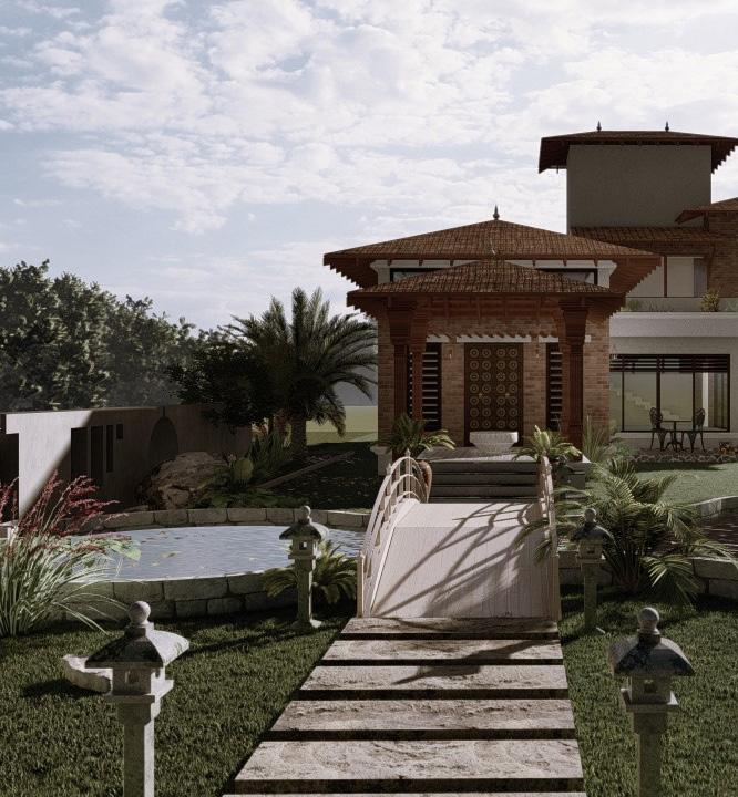
Top left : SketchUp 3D and Render of Clubhouse for Ayodhya
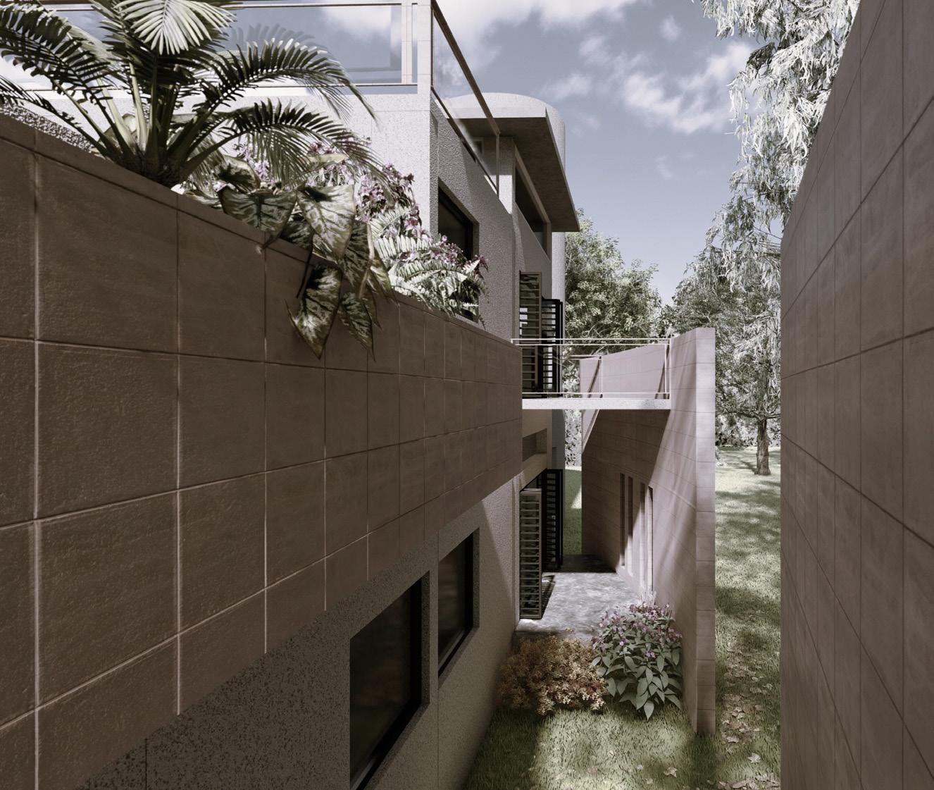
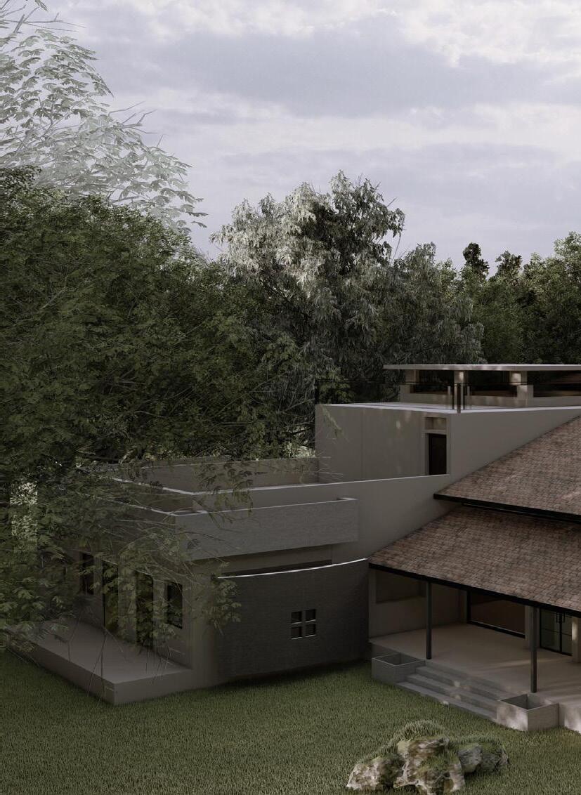
Top Right : SketchUp 3D and Render of Abhishri Residence
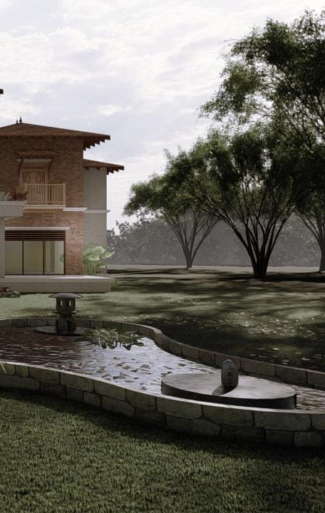
Bottom Left and Right : Malanka Farmhouse
49
Plotting Sheme
8976687382 | shaunpv23@gmail.com
linkedin.com/in/shaun-varghese
50