1
2
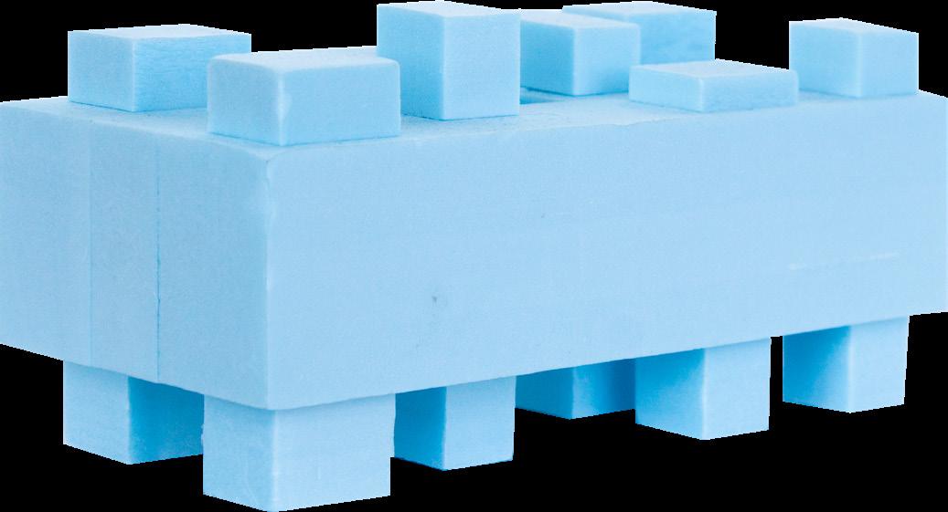
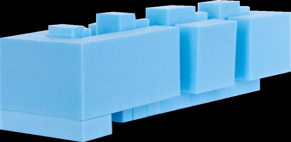
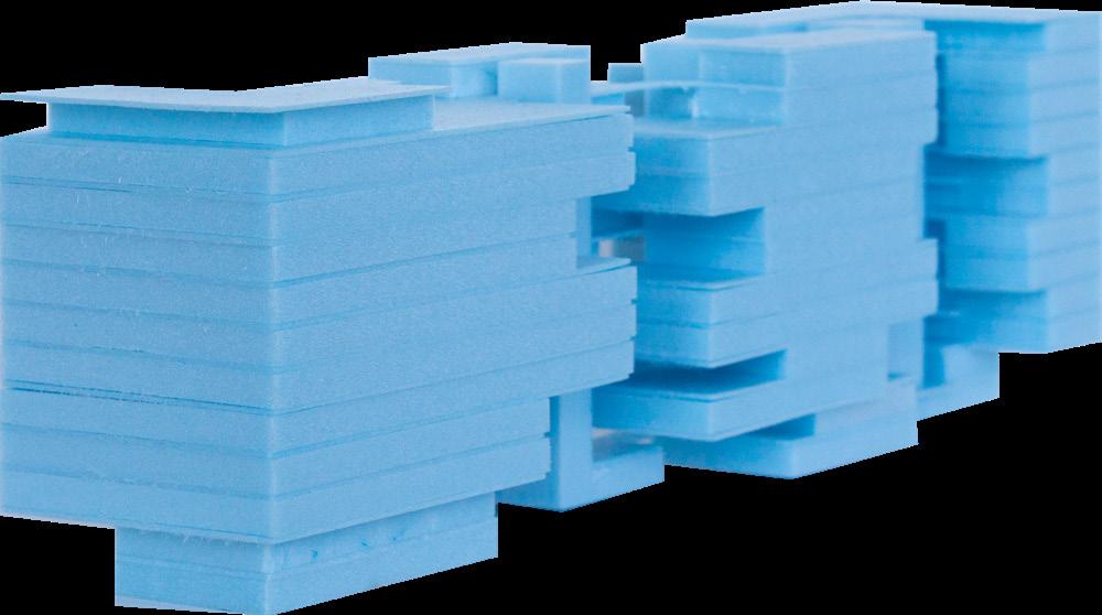
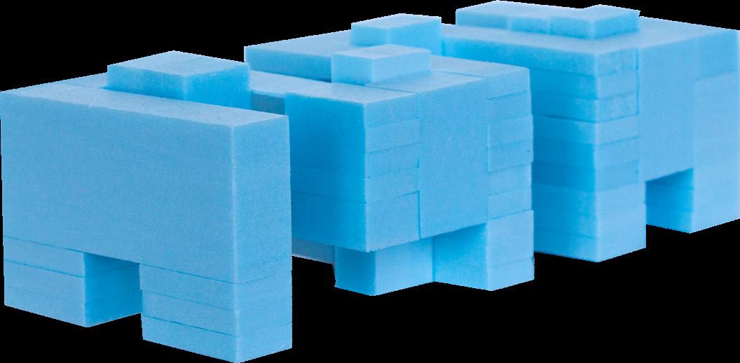
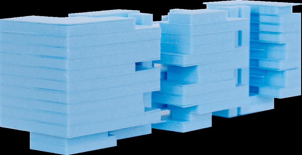
Exterior Perspective Collage

What does the city’s form actually mean to the people who live there?
With this question begins the book The Image of the City by Kevin Lynch, and it accompanied us during the design process of this project. The city is built through its image. However, it is necessary to think about what elements make up the city. According to Lynch, the city consists of 5 elements: Paths, Edges, Districts, Nodes and Landmarks. The project tries to recreate these elements of the city in a single interconnected building.
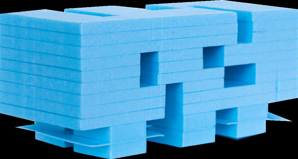
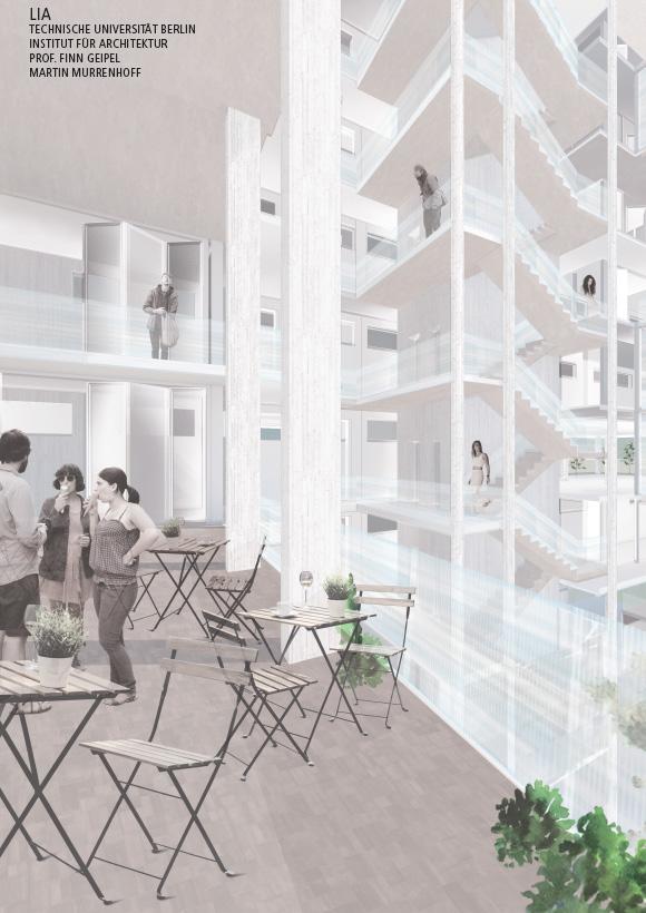
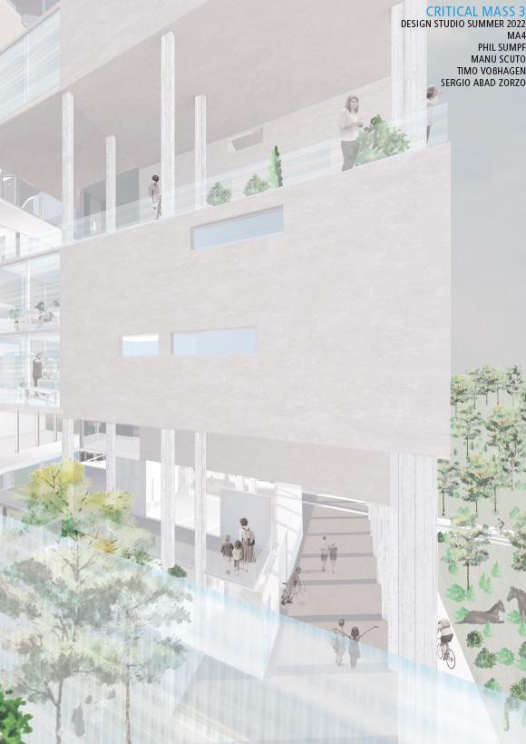
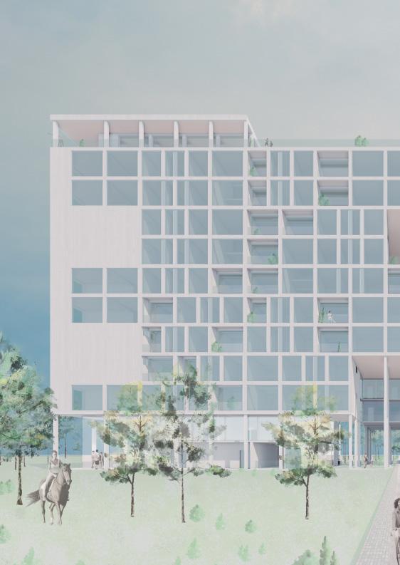
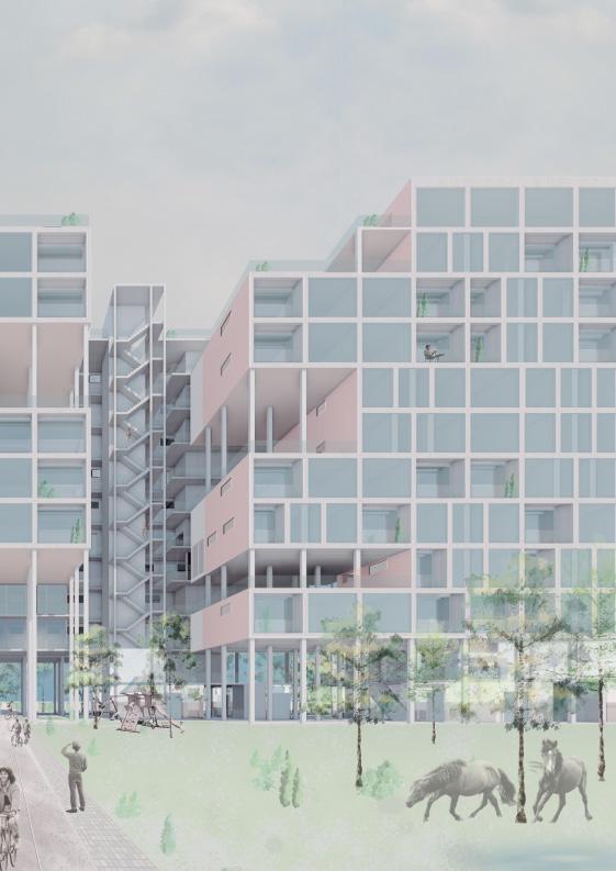
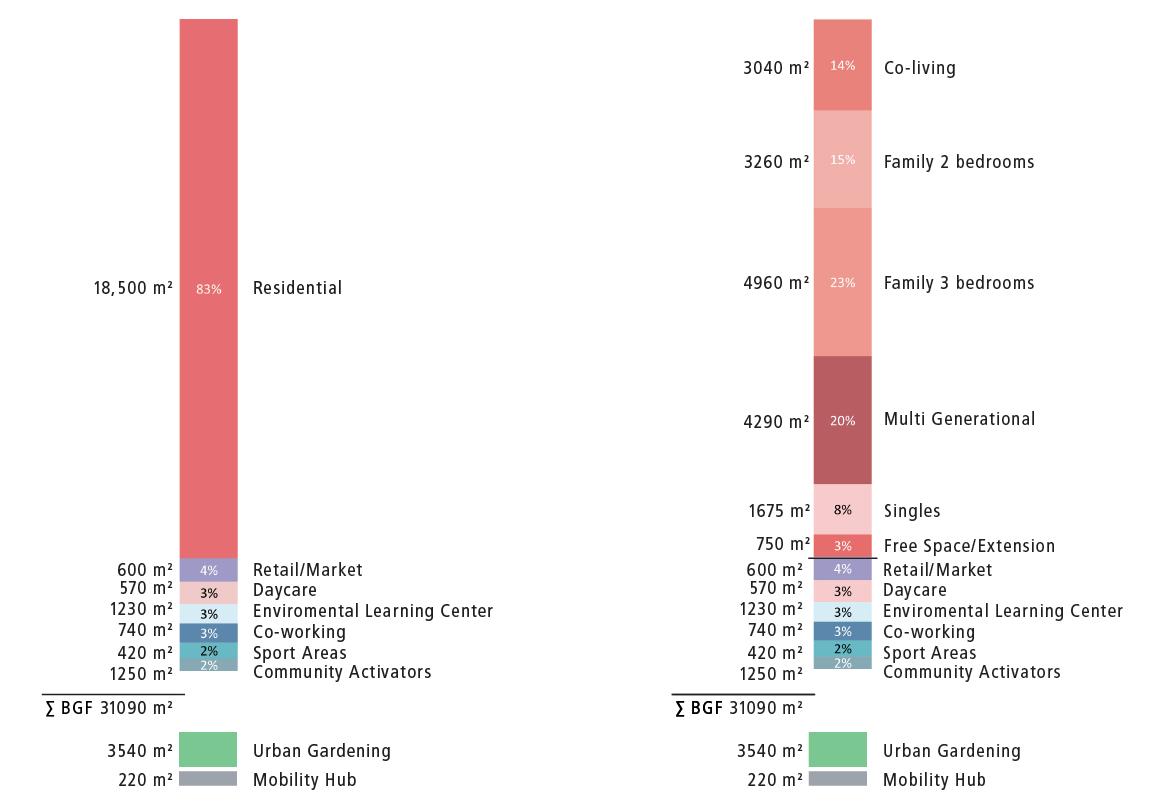
This process of condensing the program of a city, led to the challenge of solving the complexity of a 31,50m deep building with a mostly residential program. Through the implementation of cutouts in the volume, courtyards are created to carry lightto the deeper parts of the building. The apartments are complemented by so-called “Plug-In Rooms”, located in the deepest parts of the plan. These rooms can be appropriated by the residents as either extensions of their flats or shared spaces for the building’s community. The ground, first and top floor offer public programs such as retail, workshops, offices, gyms, a daycare and a viewing deck. Additionally, an environmental learning center supports the many adjacent educational institutions in the area. It also helps to raise awareness of the natural assets of the Neu-Lichterfelde area.
 Sergio Abad Zorzo Phil Sumpf Manu Scuto Timo Voßhagen
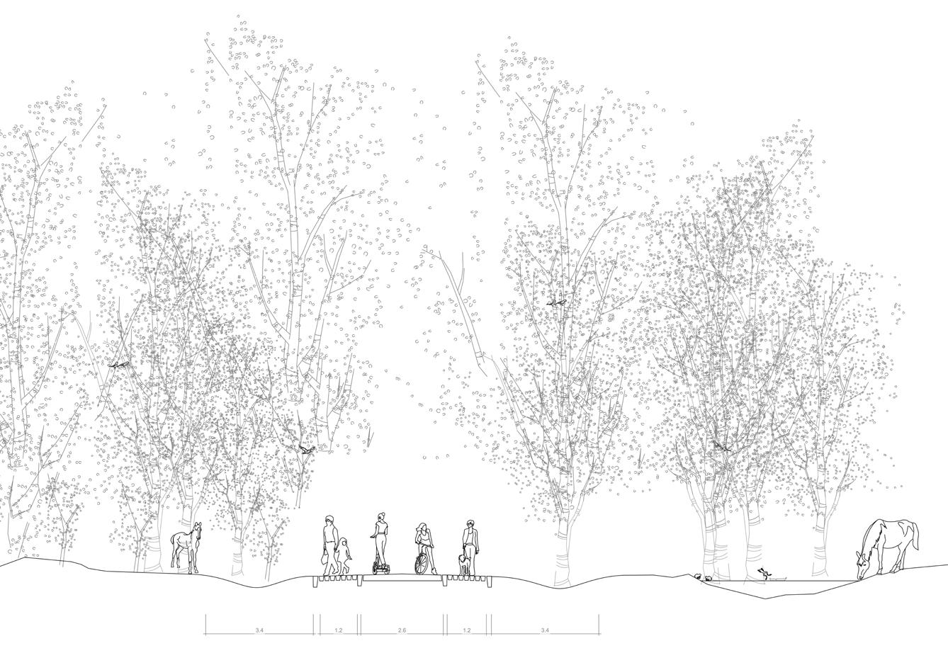
Elevation, 1:500 Section, 1:500
Isometry, 1:500
Elevation, 1:500 Section, 1:500
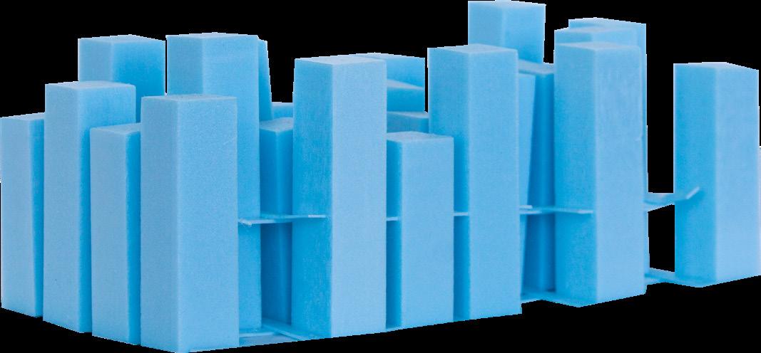
Infrastructure Axis Section, 1:300
Infrastructure Axis Isometry, 1:500
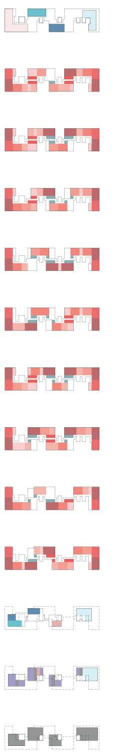
Program
Top Floor Floor plan, 1:500
Circulation
2.80
4.20
4.20
2.80
2.80
8.40
12.60
2.80
2.80
6.30 Plug-In Extension Plug-In Extension
2.80
2.80
2.80
2.80
2.80
4.20
2.80
2.80
4.20
29.40
4th Floor Floor
plan, 1:500
Plug-In Greenhouse Plug-In Bookshare Plug-In Yoga 14
4.20 A A
4.20 B B
4.20 Plug-In Cinema Plug-In Rehearsal Square
Program Circulation
• Dark Zone 4,20m: Living- and Bedroom
• Bright Zone, 6,30m: Bathroom, Kitchen
• Structural Raster of 4,20m x 4,20m
• 1,5 raster fields in the bright zone
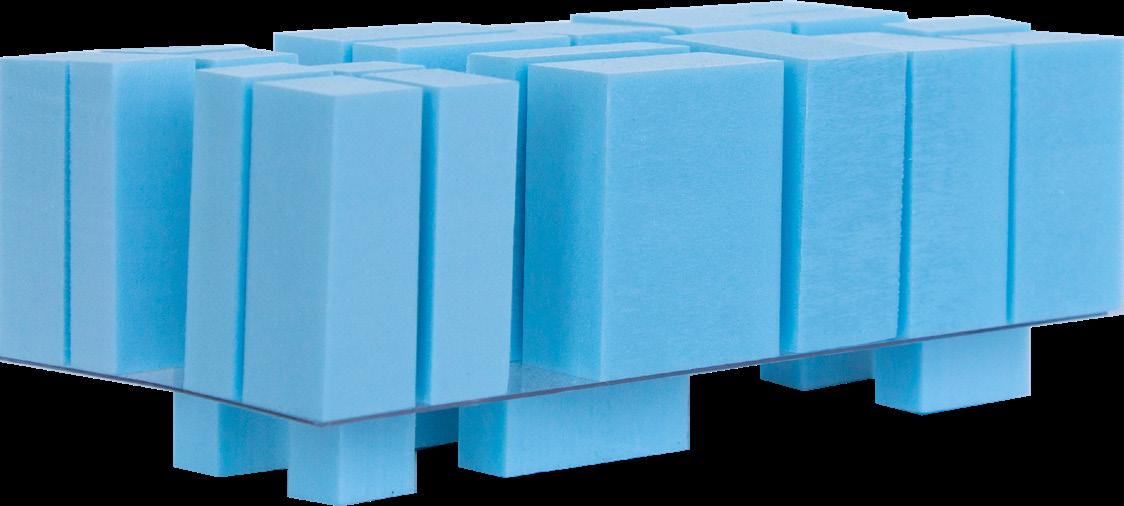
3 Load bearing w alls and beams
• placement according to light zones
• one-directionally spanning ceiling slabs
• Freedom to place non-load-bearing walls and appartment typologies
• 1st layer: Rooms
• 2nd layer: Raster and columns
Project Logic
Cocneptual Diagrams
Circulation Isometry, 1:1000 Program Isometry, 1:1000