


This study was completed by McMillan Pazdan Smith Architecture and Parks Engineering Associates. Architectural analysis, field work, and as-built drawings were compiled by Donald L. Love Jr AIA, Brian Sanders AIA, and Caitlin Shuler of McMillan Pazdan Smith. The structural analysis was performed by Stephen Parks P.E. supplemented by an analysis of the building1s foundation by S&ME consulting engineers.
Walnut G,rove Plantation - Manor House Historic Structure Report


Walnut Grove Plantation is considered to be one of the finest surviving examples of an upcountry plantation in the state of South Carolina. The plantation1 s manor house currently serves as a house museum, giving its visitors a real taste of what living in the upcountry at the time of the American Revolution was like. The house, outbuildings, and property were donated to the Spartanburg County Historical Association by the Moore family in 1961. The Historical Association then took on the task of renovating the house and creating the visitor's experience that is the Walnut-Grove Plantation. The property has since been deeded to the Spartanburg County Foundation but it is still managed by the Historical Association. In an effort to address any known issues and ensure that the building continues to sustain itself as a house museum, the purpose of this study is to provide a thorough assessment of the interior and exterior finish materials, the foundation and structural system.
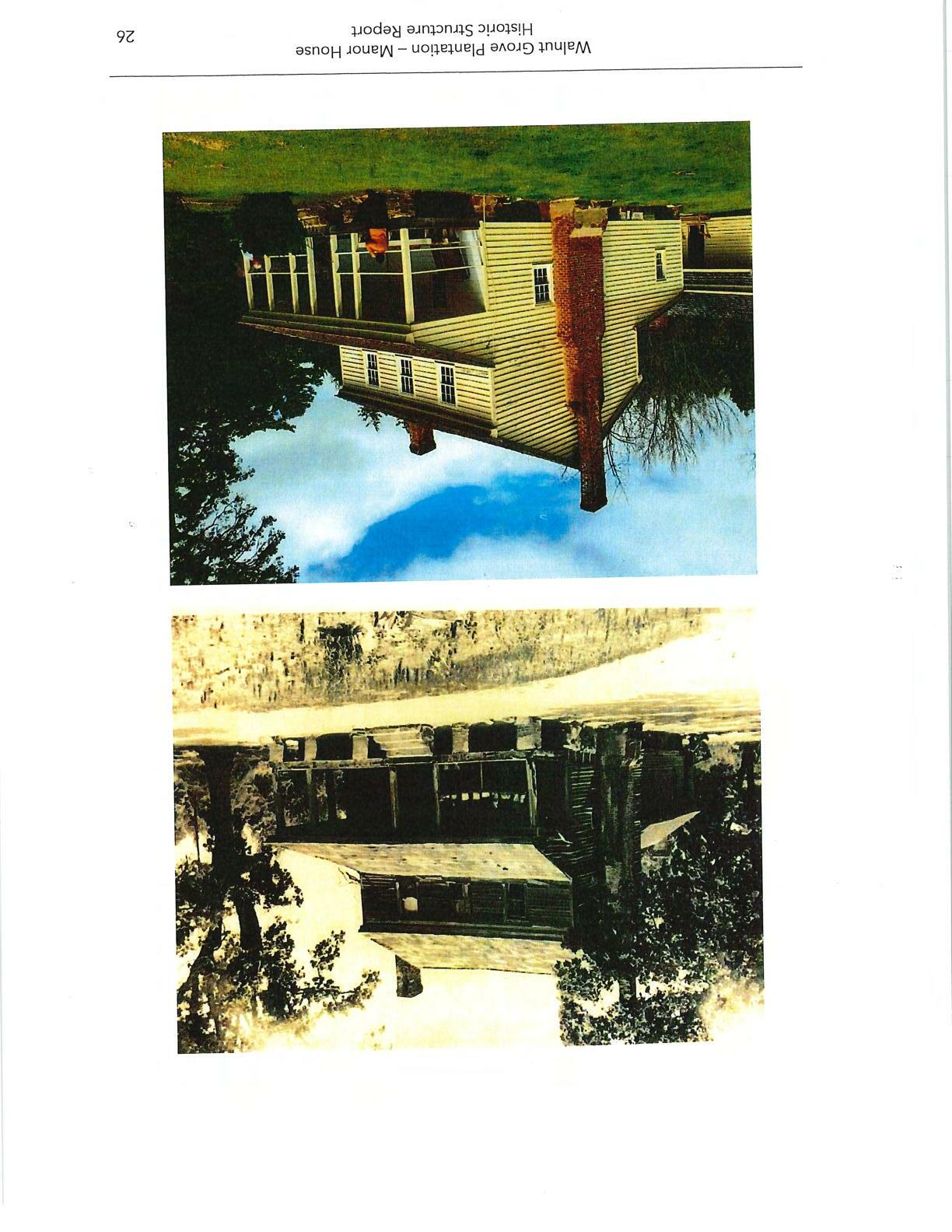
The process began with architectural and engineering teams field measuring the interior and exterior of the house, taking photographs, and gathering as much data as possible about the current condition of the building and its structural system. Input from the Executive Director of the Historical Association was critical to the understanding of the number and extent of recent repairs and the background for them. The building measurements were then used to create a 3D model of the house, an important element in understanding the challenges of the project. The model can also be used to create the drawings that will be needed later to describe the repair process. A general contractor was enlisted to carefullyremoveportions of the exterior and interior wall finishes so that the structuralsystem could be studied in detail. Additional site visits and study provided the information to complete the report. Photographs were used to compare the appearance of the building as it has evolved from before the renovation in the 1960's to present day.
Walnut Grove Plantation - Manor House Historic Structure Report



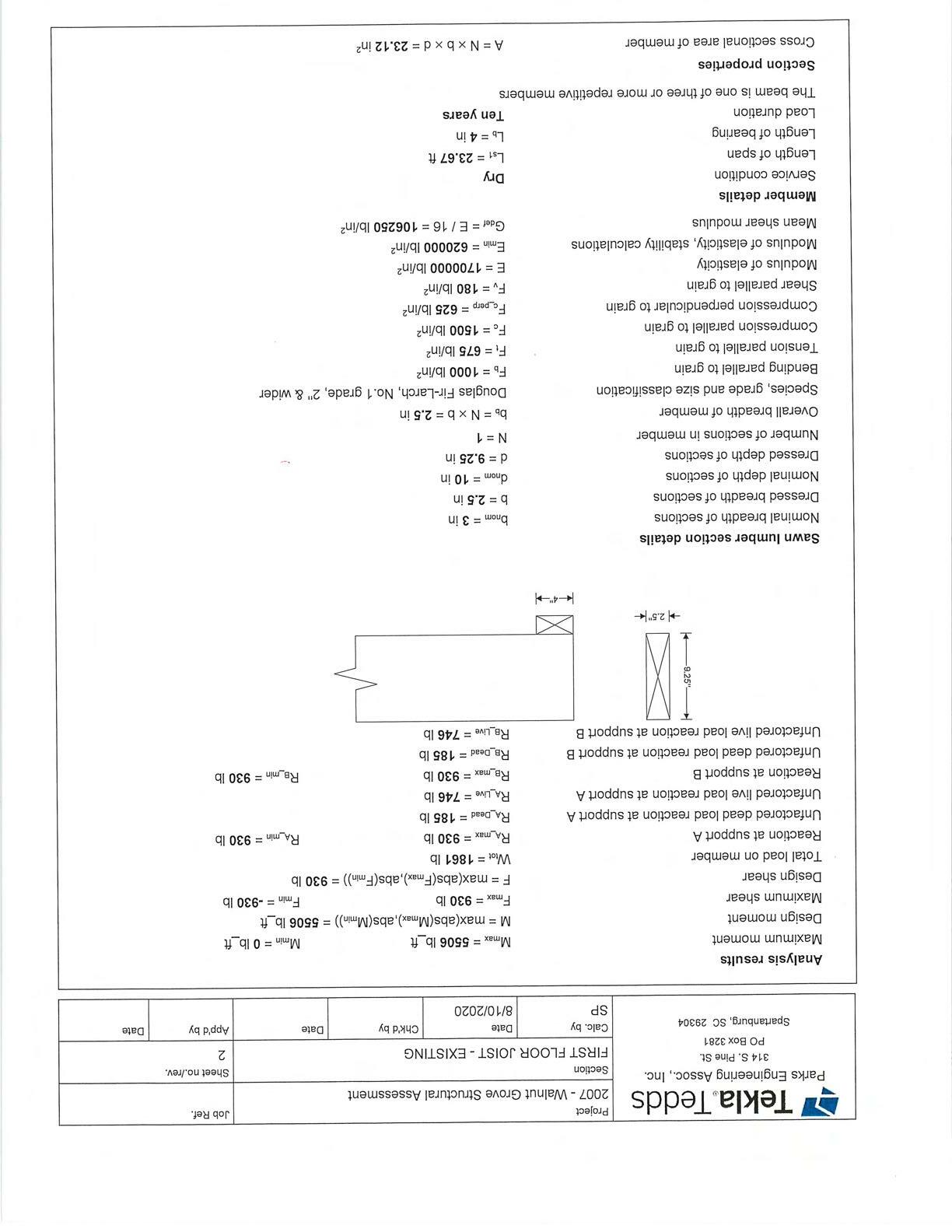


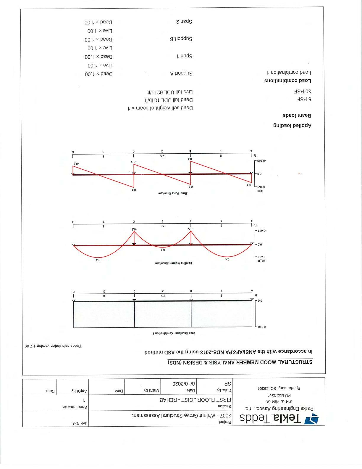
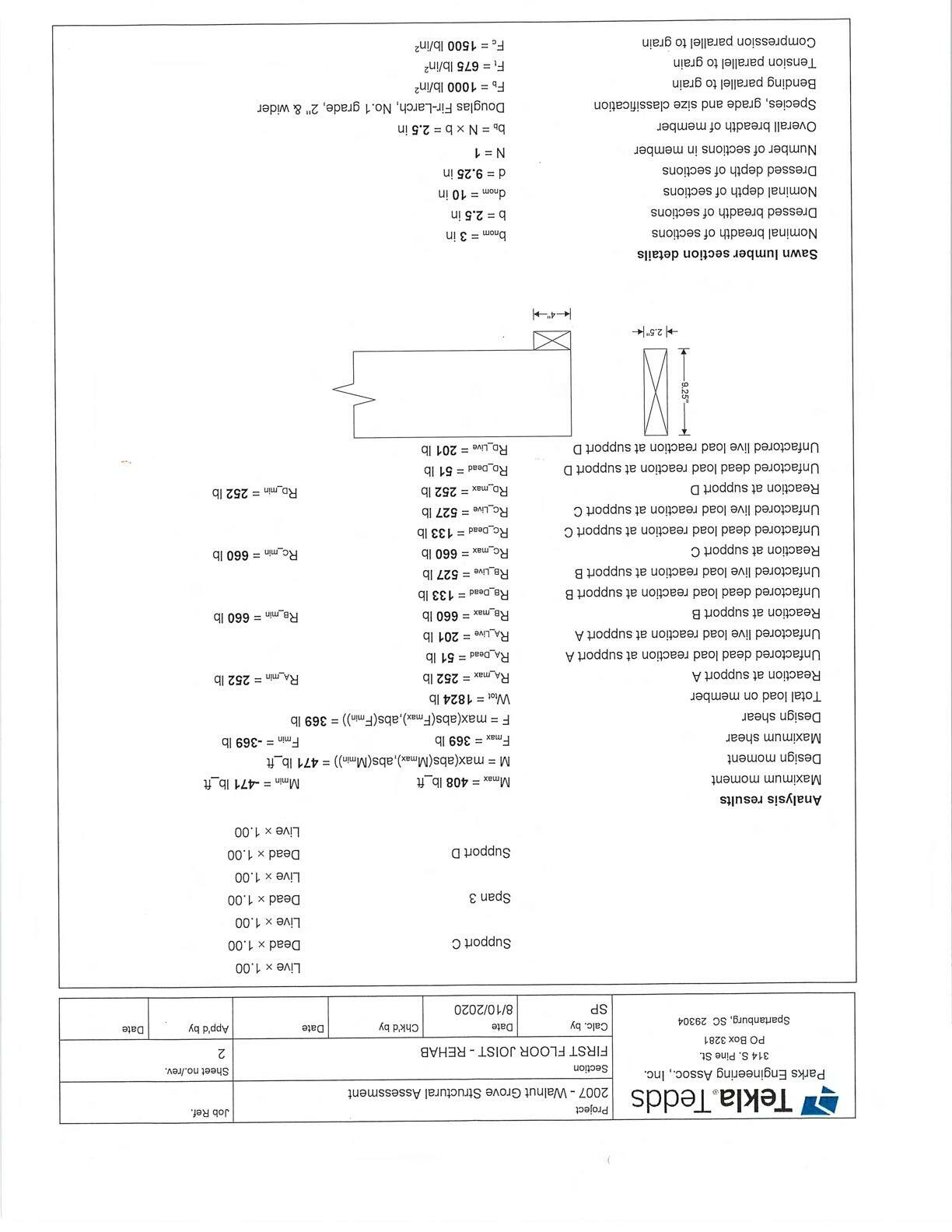
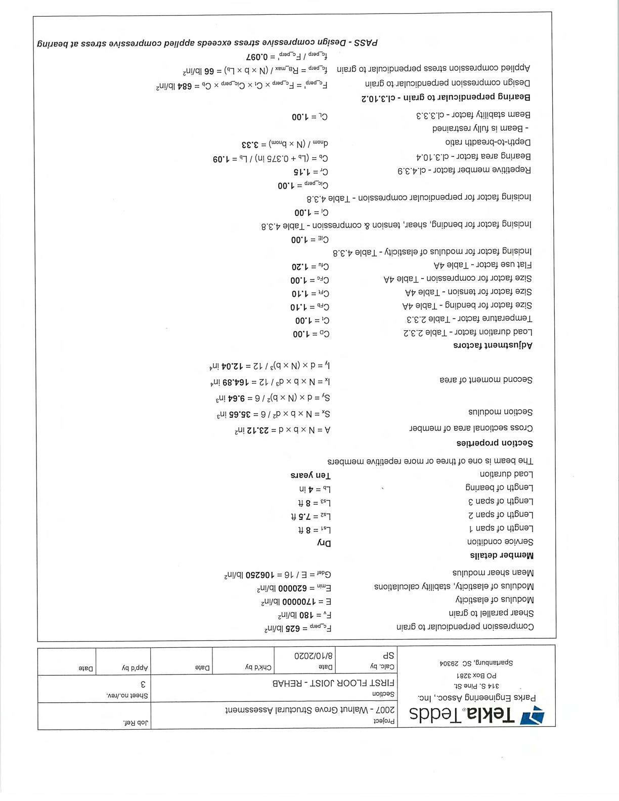



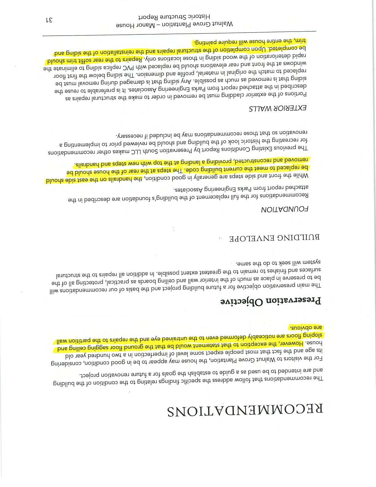
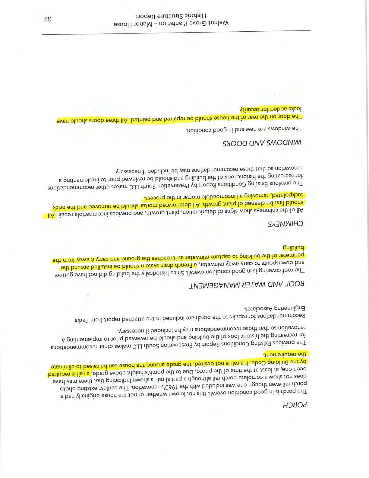
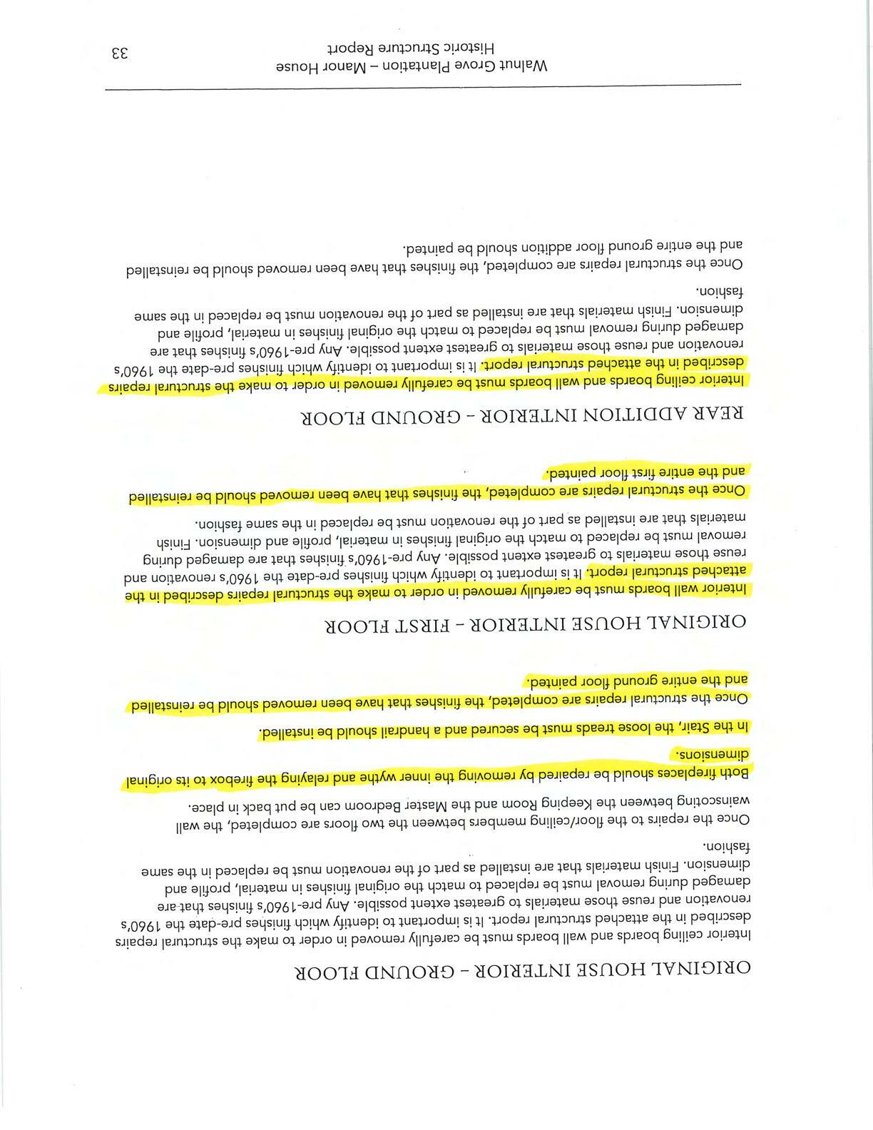
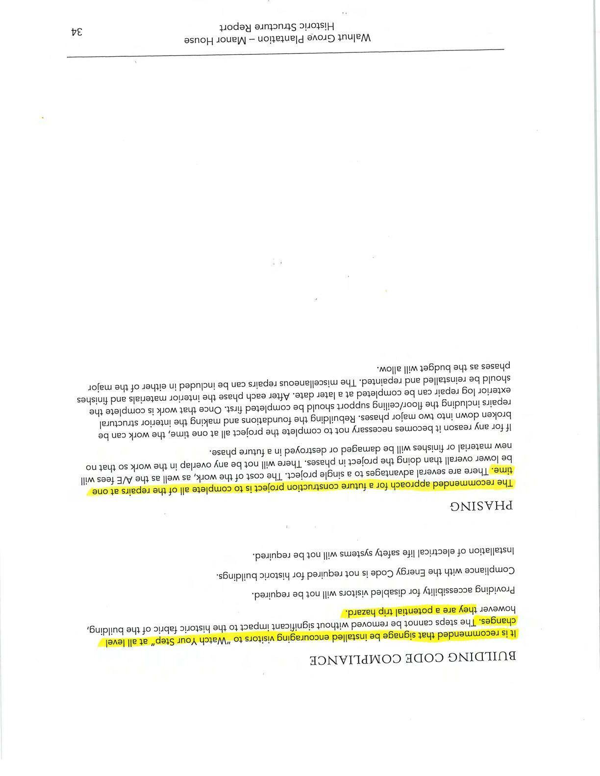


August10, 2020
Attherequestofthe Spartanburg CountyHistoricalFoundation,thisofficehasconducted an assessment of the existing structural conditions of the Manor House at the Walnut Grove Plantation site. The purpose of this structural assessment is to identify and evaluateexistingconditionsofthestructuralcomponents ofthehouse,assessanycurrent damage and provide preliminary guidelines for required and possible repair solutions. Thisreportwilladdressonlythestructuralcomponentsandtheir currentstateandis to be accompanied by an Existing Conditions Report prepared by McMillan Pazdan Smith Architects. The information contained in both reports will serve to provide a basis for requiredrepair,renovationandrehabilitationgoing forward.
A number of previous restorations have been undertaken to address specific areas of concern - some of which are described in an Existing Conditions Report prepared by Preservation South in the Fall of 2016-a copy of which was provided to this office for review.
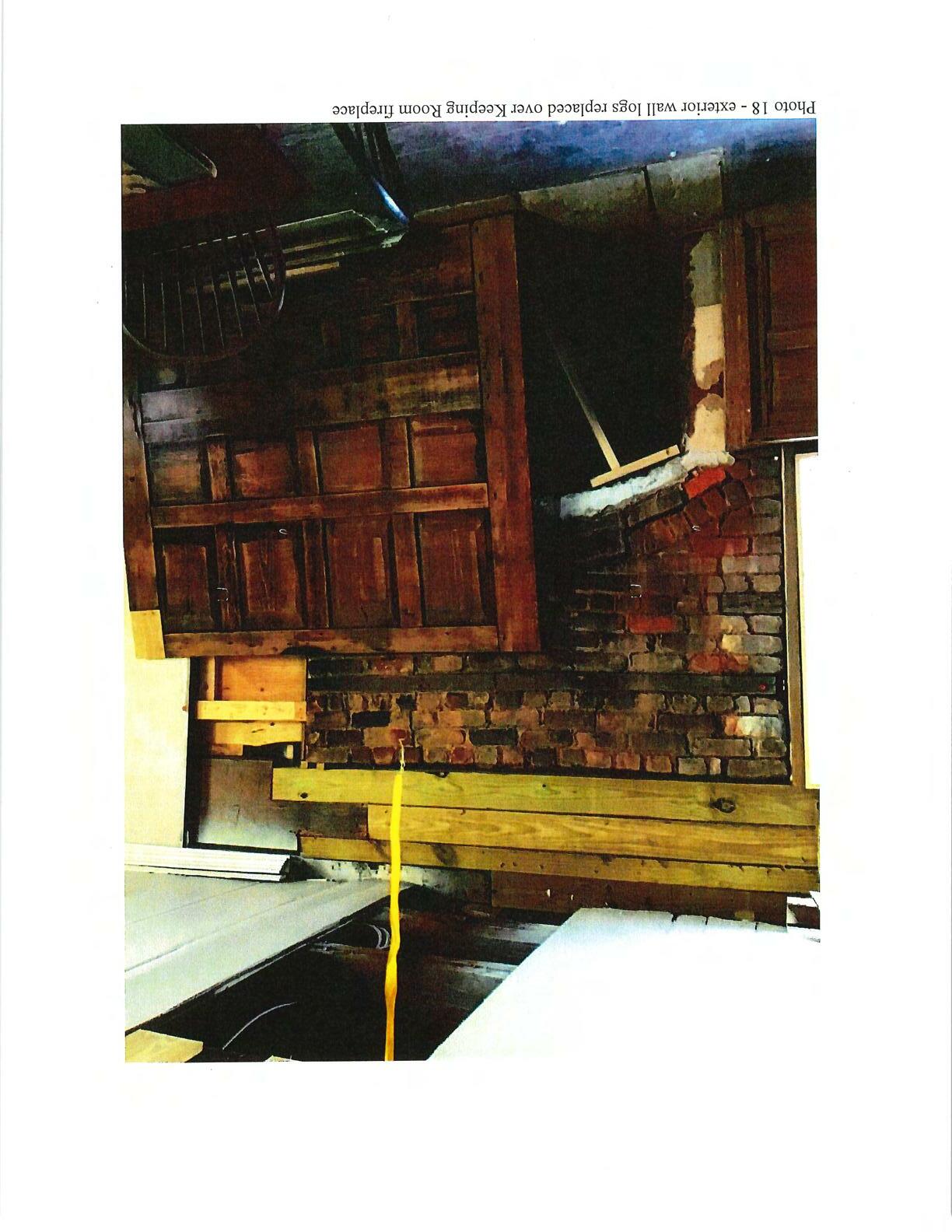
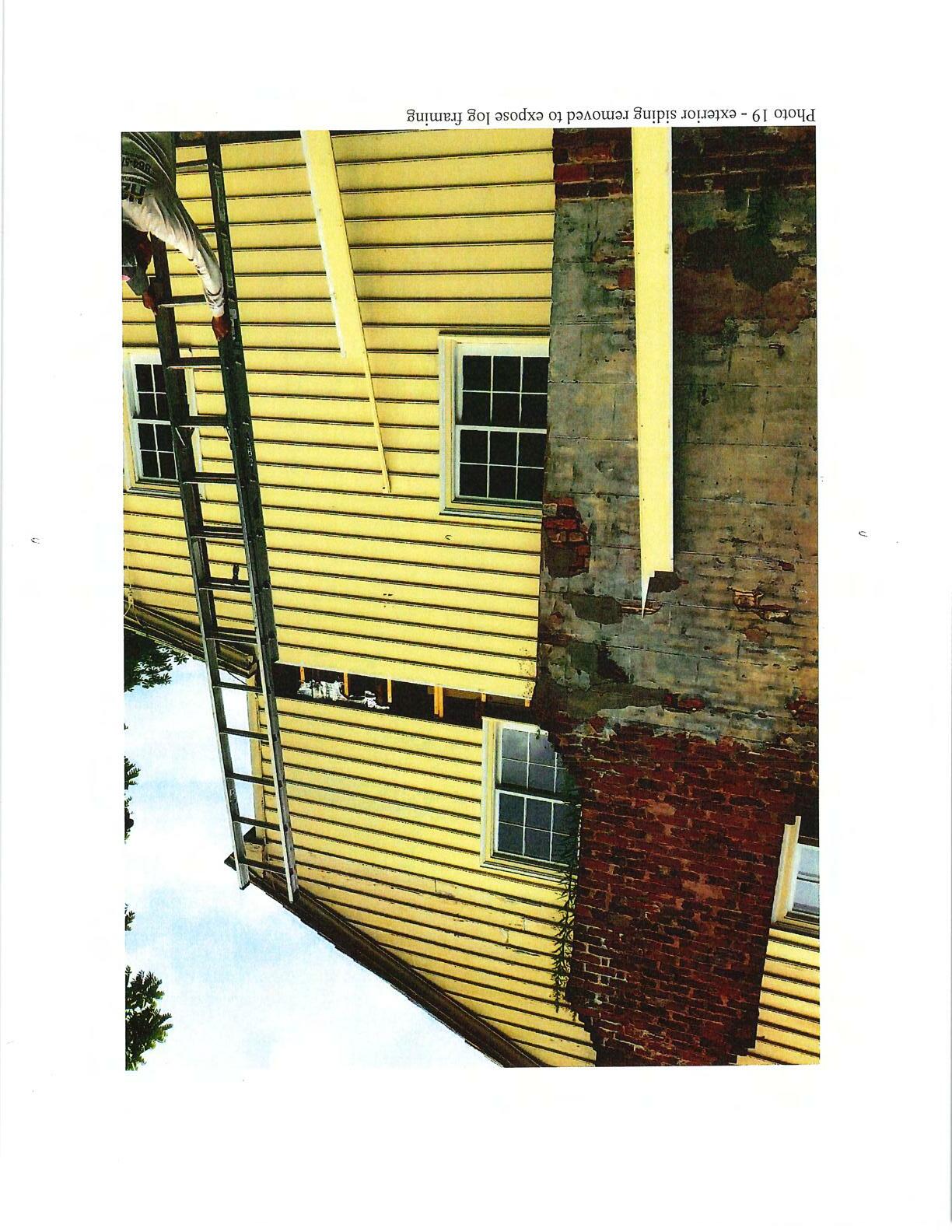
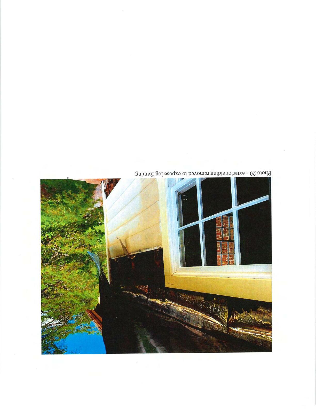
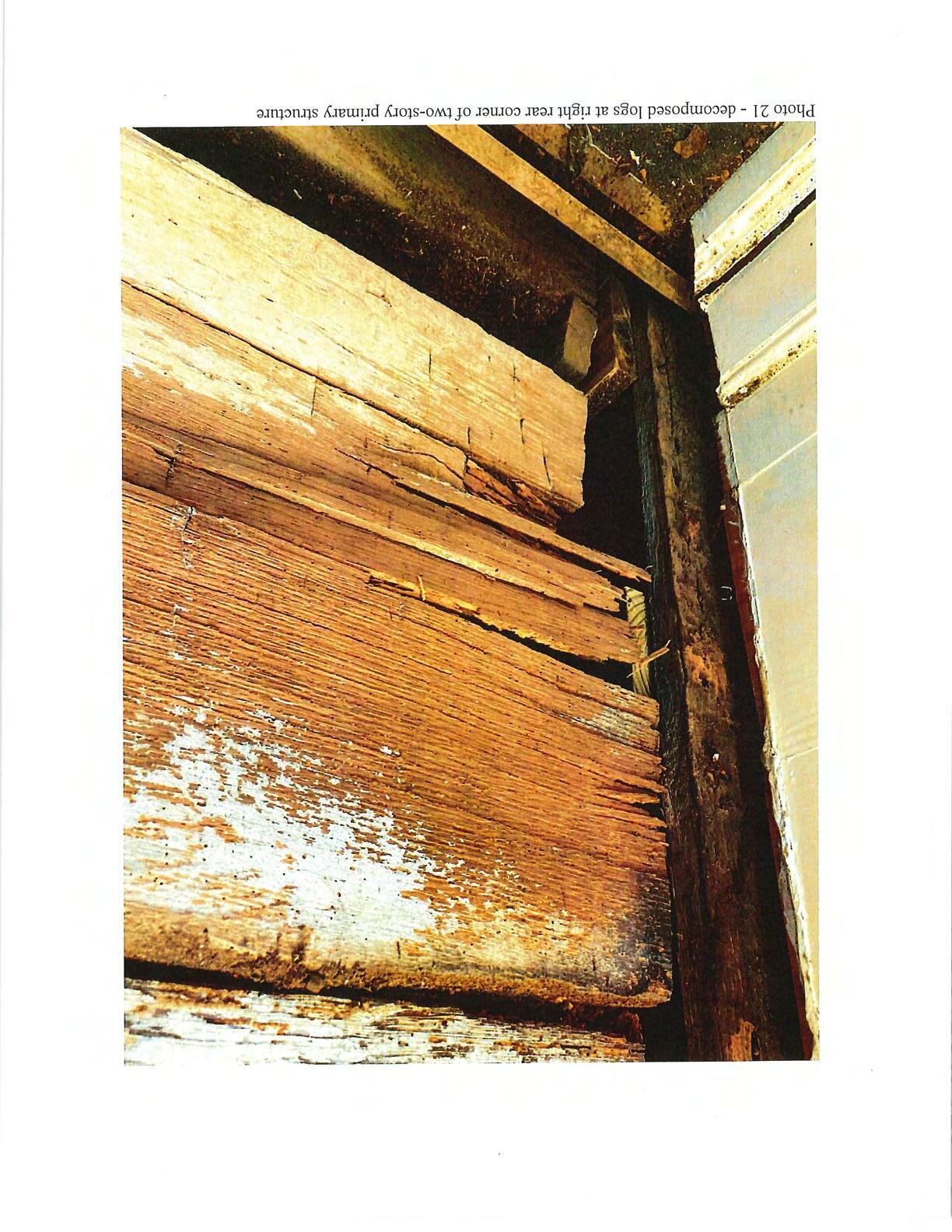
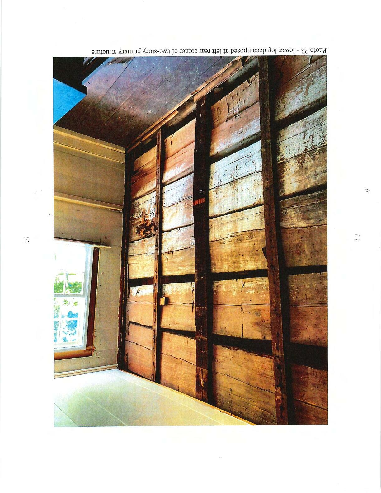
This reportis organizedto address four distinct areas of structural concern-foundations and ground floorframing, firstfloorframing, logframingofexteriorwalls andchimneys. Thereport will address the current condition ofthese four areas ofstructuralcomponents and provide preliminary recommendations for repair and rehabilitation. The current structural condition of the components was determined through multiple site visits by both this office as well as a report prepared by S&ME, Inc. addressing the first floor framing andfoundationconditions. A copy ofthatreportis includedas anattachmentto this report. Some areas of the exterior siding were removed to expose representative areasoftheoriginalexteriorlog framingforvisual assessment.
TheManorHouseisarrangedasatwo-storyprimarystructurewithafrontwrap-around 314 S. Pine Street,POBox3281, Spartanburg, S.C., 29304 Phone (864) 316-3776 emailswparks@charter.net

Report ofStructural Assessment
Walnut GrovePlantationManorHouse
1200 Otts ShoalsRoad, Roebuck, SC August 10, 2020
Description:
The floor of the rear addition is supported on approximately 8" diameter log joists at approximately 24" to 30" on centerspanni,ng side-to-side to a center12xl2 heavy timber girder which spans front-to-rear of the addition and to 12xl2 heavy timber sills along boththerightand leftexteriorwalls (photo 7). A supplemental2xl2was addedtothe
rightside sill at some pointintime. The centralinterior12xl2girderis supportedontwo intermittently spaced stonepiers andintersects the rear sill ofthe single story portion and the aforementioned rear sill of the two-story portion. The rear12xl2 sill is supported on four irregular shaped and sized stone piers - all of which are partially grouted and partiallydrystacked(photo7).

• The existing stone masonry piers exhibit a variety of conditions including drystack with no groutbond, irregular shapes and sizes, lack of contact between pier and floorjoist or sill. Some piers have retrofit concrete pads poured under them while some bear directly on the ground as likely originally constructed. It could not be determined fromvisual inspection the extent to which these concrete pads provide uniform support for the piers as well as the depth or consistency of the pads. It is likely the piers currently resting on concrete pads were dismantled to allow forplacementoftheconcrete pads and rebuiltin a1960'sera renovation.
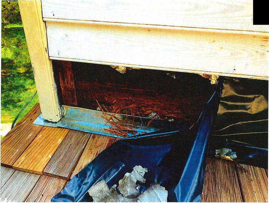
• Rear sill has suffered significant water damage near the rear entry door (reference S&MEreportpage21, photo 5)
• No attachment appears to be in place for the central heavy timber girder to the sillsateachofitsends.
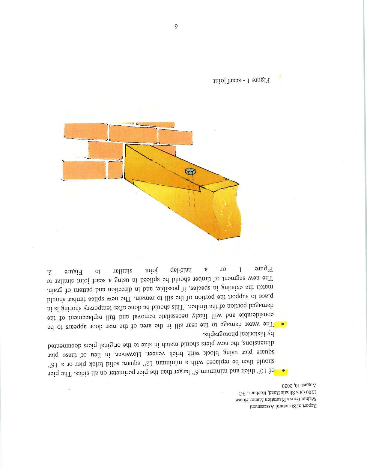
• It is recommended that each ofthe existing s one piers be dismantled - after proper shoringsupport is in place-and replaced with brickpiers as were originally in lace. Each pier location -including those that currently have a small concrete pad at their base - should have a new concrete footing placed at a minimum of 1O" below existinggrade. The 1ew footings should be aminimum
Walnut Grove PlantationManorHouse
1200 Otts ShoalsRoad, Roebuck, SC August 10,2020
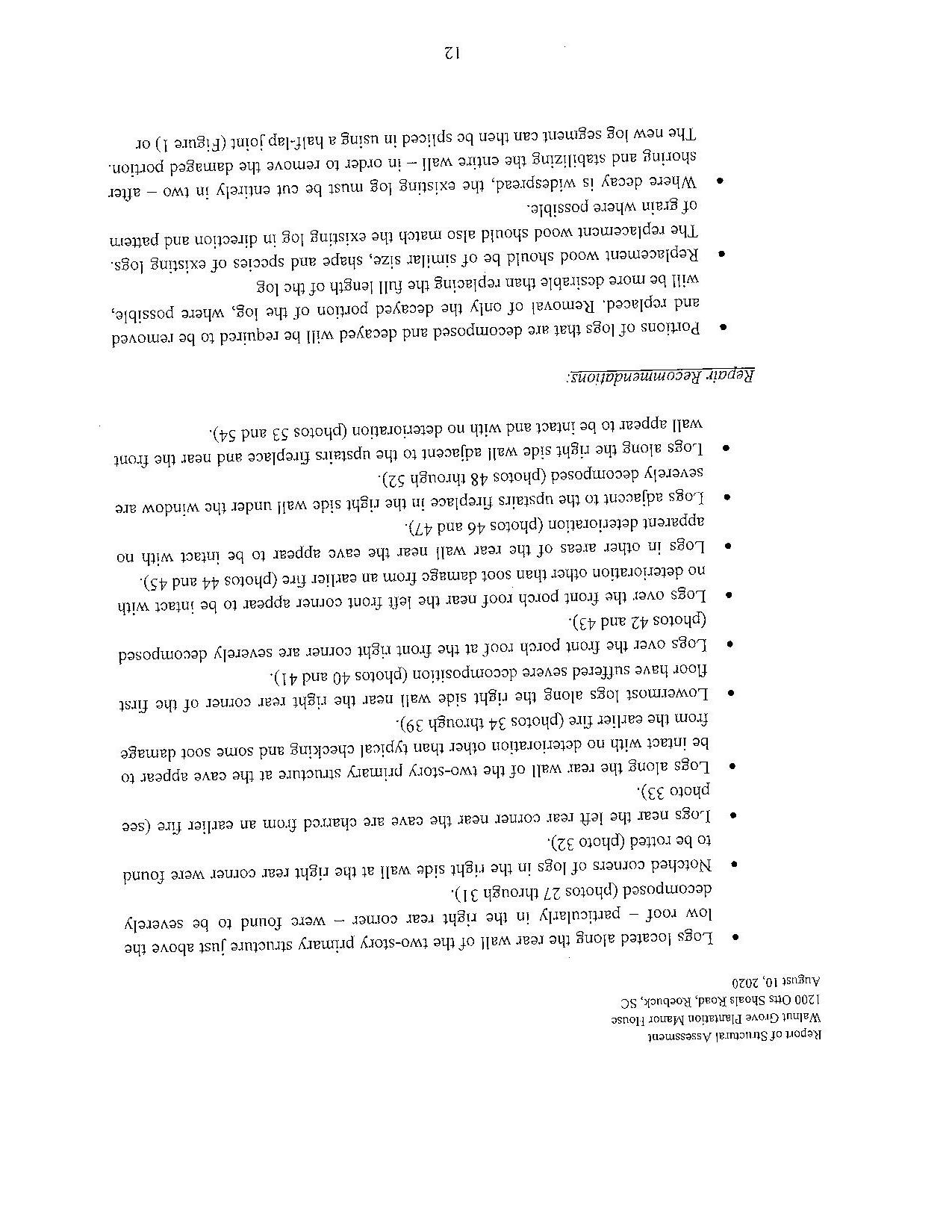
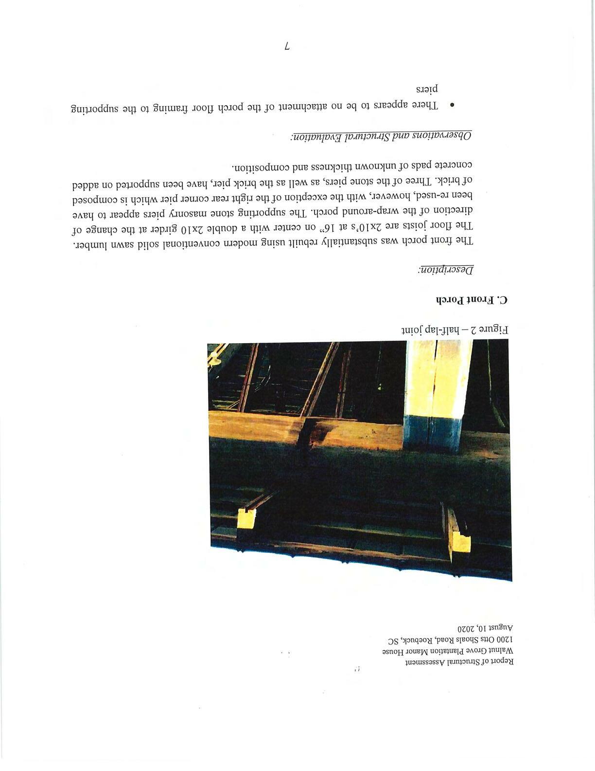
Figure2-half-lapjoint
Description:
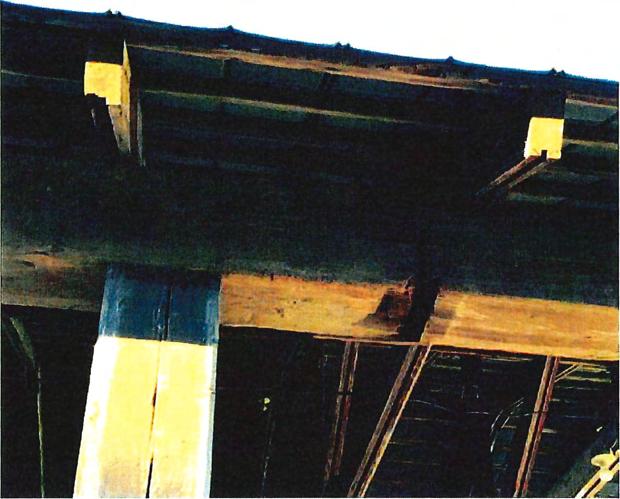
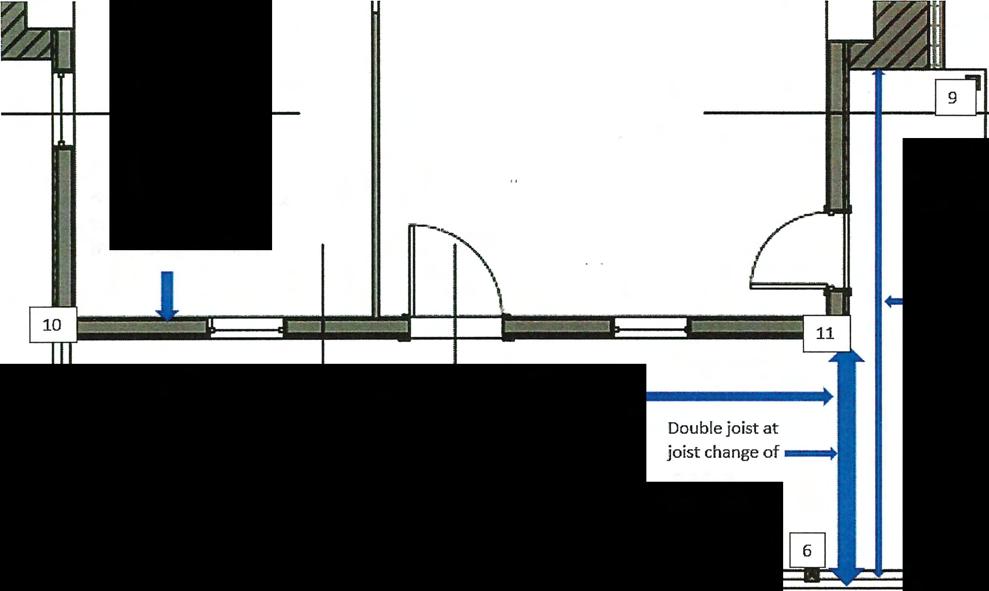
The front porch was substantially rebuilt using modern conventional solid sawn lumber. The floorjoists are 2x10's at 16" on center with a double 2x10 girder at the change of direction of the wrap-around porch. The supporting stone masonry piers appear to have beenre-used,however,withtheexceptionoftherightrearcornerpierwhichiscomposed ofbrick. Three ofthe stonepiers, as well as thebrick pier, havebeen supported on added concrete padsofunknownthicknessandcomposition.

• There appears to be no attachment of the porch floor framing to the supporting piers
Walnut GrovePlantation ManorHouse
1200 OttsShoalsRoad, Roebuck, SC August 10,2020
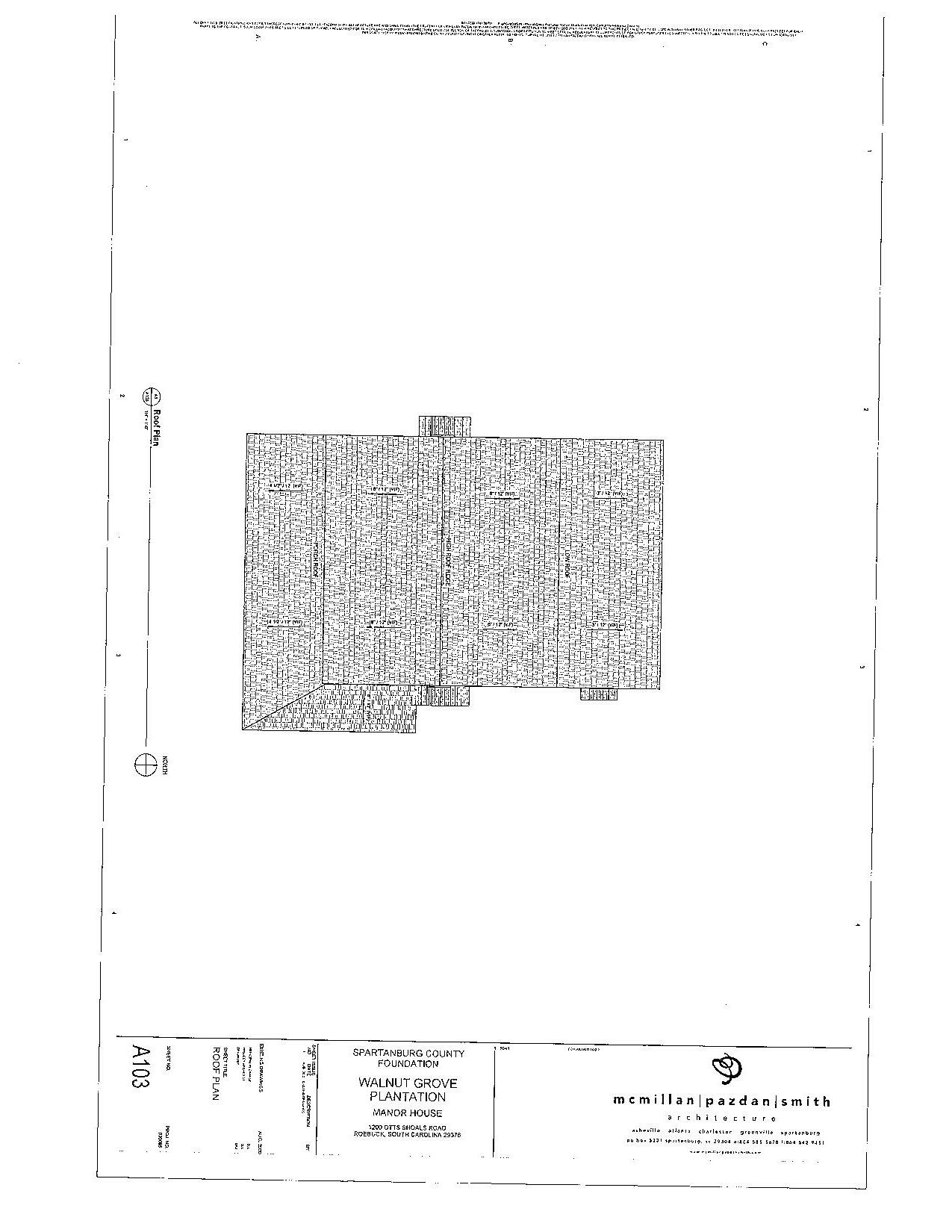
Recently anattemptwasmade to supplement andrepair theroof framingbyadding posts and new collar ties - apparently to shore up the ridge in the absence of a ridge board (photo12). However, thisrepair attempt seems tohavebeen performed in arandom and haphazard way and is likely imposing additional load on the ceiling joists than is not withintheceilingjoists'capacity.
Generally accepted practice is that structural repair of fire damaged framing is often not required when the char depth is less than 6 mm (0.2") or no more than 10% of the member's original cross-section. Access to the most severely charred rafters to definitivelymeasurethedepthof charring wasnotavailable. However, itappearsthatthe rafters shown inphoto11neartheleftrearcorneroftheprimarystructuremay becharred beyond the 10% limiting depth to retain acceptable structural integrity. It is, therefore, recommended that these six rafters be supplemented with new rafters of similar size and spacing.
Description:
The rear addition ceiling and roof are framed with a combination of hand-hewn lumber and milled lumber. The ceiling is framed with 4x6 hand-hewn joists. The rafters are nominal 2x4joists supported by lx4 posts to the ceilingjoists (photo 13). A portion of theceilingjoistshavebeenreplacedwithconventionalsolid-sawn2xl0's(photo14).
• As seen in photo 14, the rafters are supported against the rear wall of the twostory primary structure by nailed attachment to the clapboard siding and furring strips-no ledgerispresent.
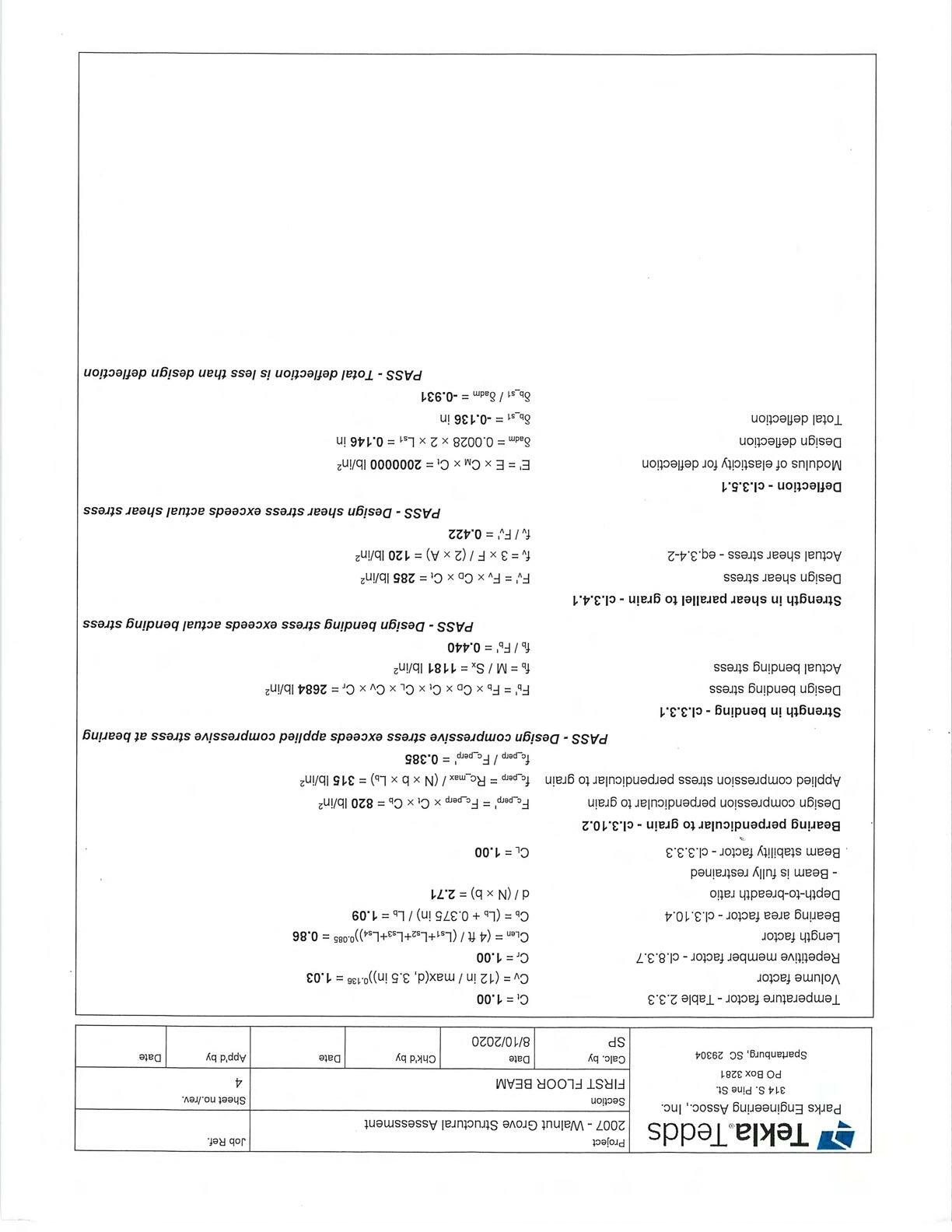
• Structural calculations were performed to determine the adequacy of the existing 2x4rafterstospanthewidthoftherearadditionwithanintermediatesupportat


PARI<SENGINEERINGASSOCIATES, INC. StructuralEngineering REPORT
WALNUTGROVEPLANTATION-MANORHOUSE 1200OTTSSHOALSROAD ROEBUCK�,SC
PREPAREDFOR:
SPARTANBURGCOUNTYHISTORICALASSOCIATION
StephenParks, PE PARKSENGINEERINGASSOC., INC.

314S.PineStreet,POBox3281,Spartanburg,S.C.,29304 Phone(864)316-3776emailswparks@charter.net


WalnutGrovePlantationManorHouse
1200Otts ShoalsRoad, Roebuck, SC August 10, 2020
• Many ofthe log floor joists have split horizontally because the lower two-thirds ofeachjoists' depthwasnotchedtoallowittorestonthesill (photo3).
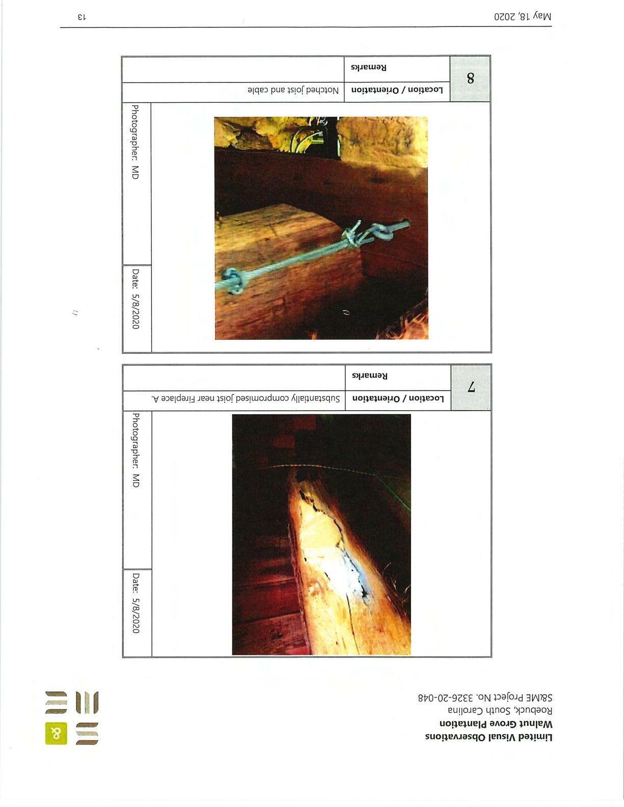
• The log joist adjacent to the Master Bedroom fireplace shows significant rot and waterdamage(reference S&MEreportpage 13, photo7)
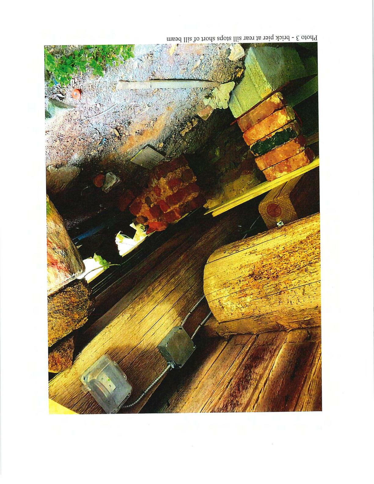
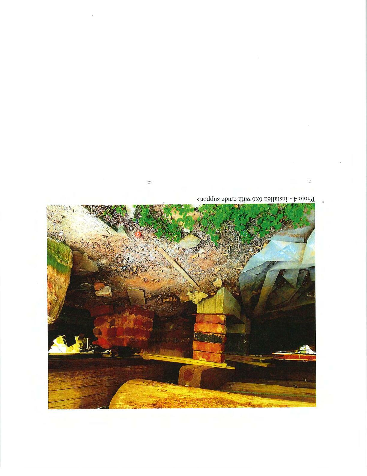
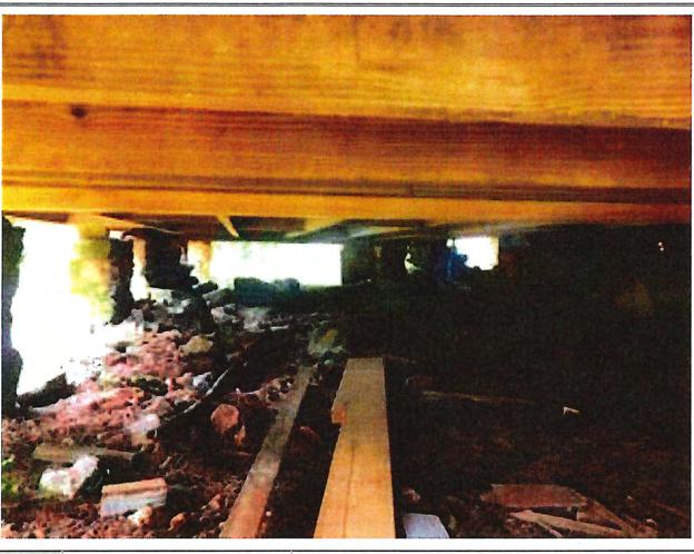
• A 6x6 timber sill beam has been added near the right rear wall to provide additional support for the front-to-back floor joists - presumably because ofthe horizontal splitsoccurringin theexistingjoists or deterioration ofthejoists. This sill is crudely supported with a combination offloor jacks, CMU and brick drystackedpiersandwoodshims (photo4).
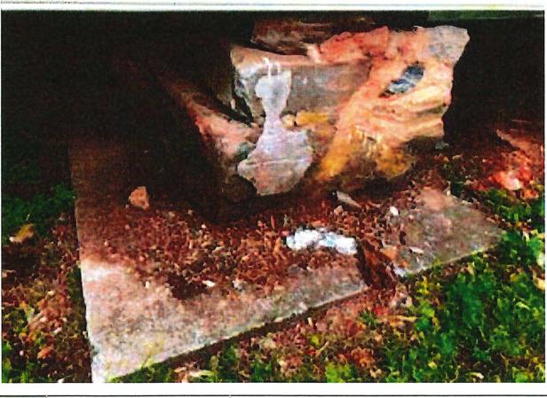
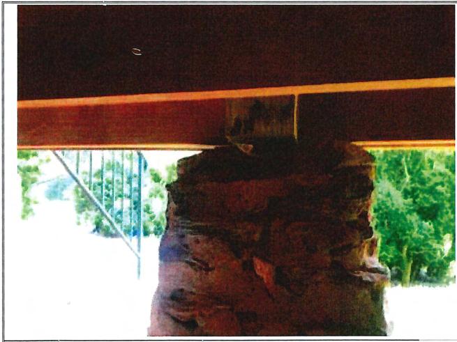
• The existing stone masonry piers exhibit a variety of conditions including drystack with no groutbond, irregularshapes and sizes, lack ofcontact betweenpier and floor joist or sill. Some piers have retrofit concrete pads poured under them while some bear directly on the ground as likely originally constructed. It could not be determined from visual inspection the extent to which the concrete pads provide uniform support for the piers as well as the depth or consistency ofthe pads. (photos 5 and 6). It is likely the piers currently resting on concrete pads were dismantled to allow for placement of the concrete pads and rebuilt in a 1960's era renovation. Based on photo 65, it appears the original piers were constructedoutofbrickandnotstone.
• Inatleast oneinstanceitappearsa piermayhavebeenremoved andwasreplaced witha 8x8timberpost (reference S&MEreport page 9)
• On both the right and left sides, conventional modern solid sawn lumber of varying sizes has been installed to supplement the existing heavy timber sills because ofwater damage, insectdamage and dry rot. Some ofthis supplemental framing appears to have been installed improperly - specifically a portion along the right side adjacent to the Keeping Room fireplace which was notched more than is allowed by the current International Building Code (JBC) (see page 16, photo#14ofS&MEreport)
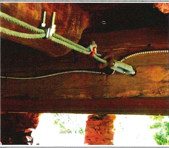
• The central cable of the three cables installed to repair the front sill is not connectedattherearsill.








Roebuck, South Carolina S&ME Project No. 3326-20-048
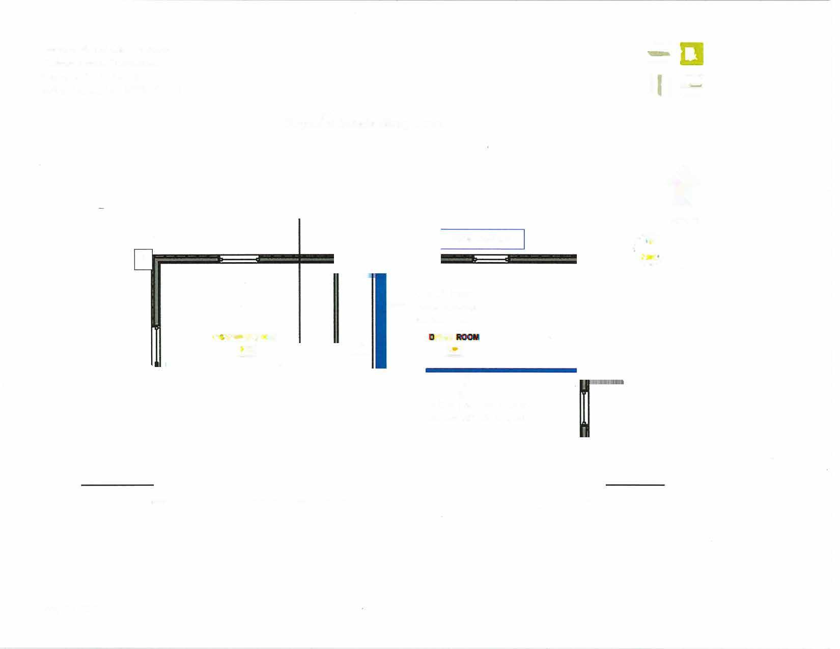
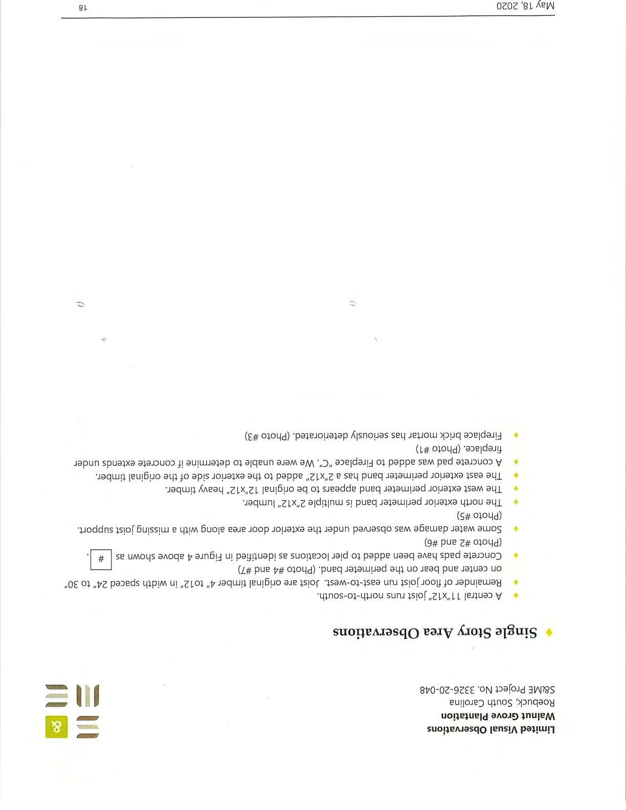
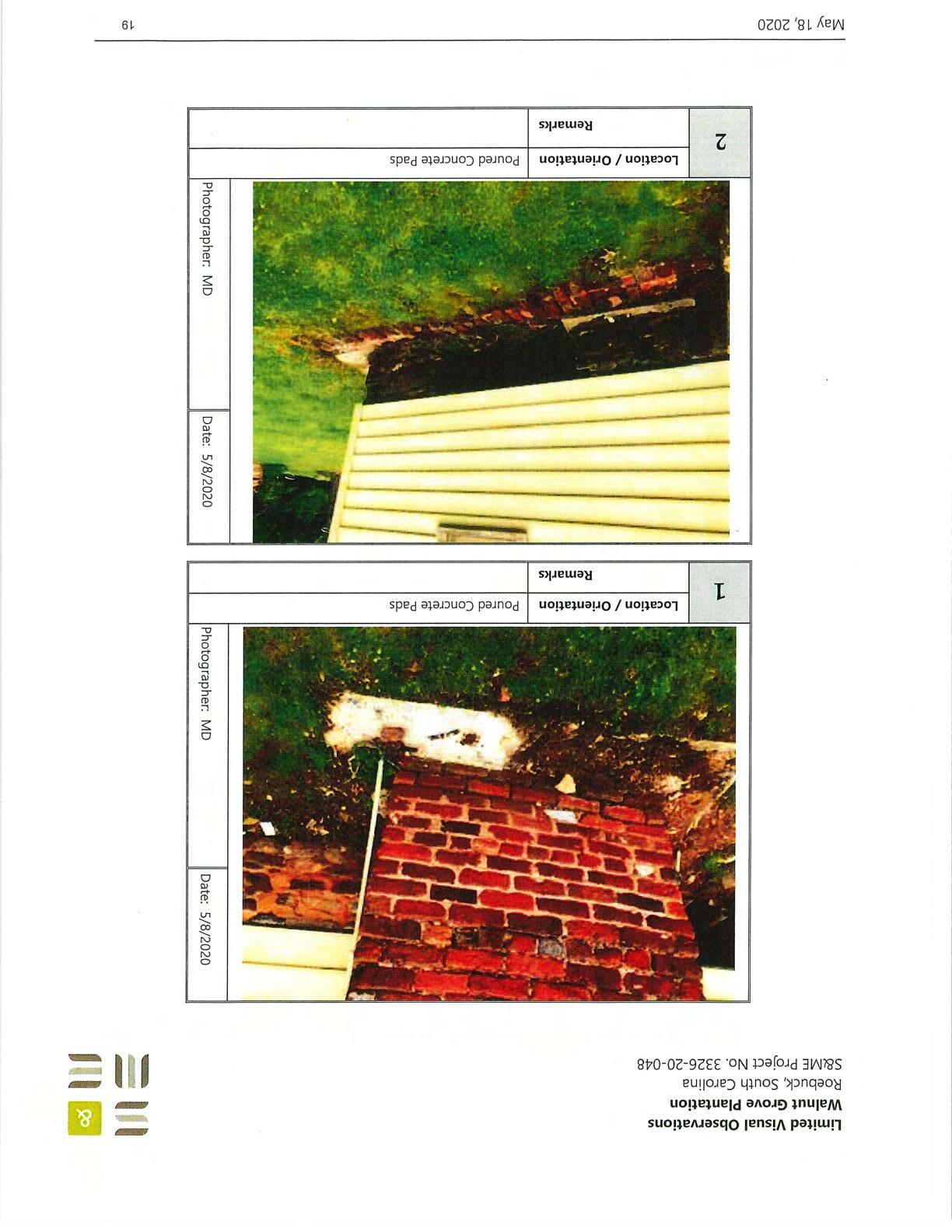
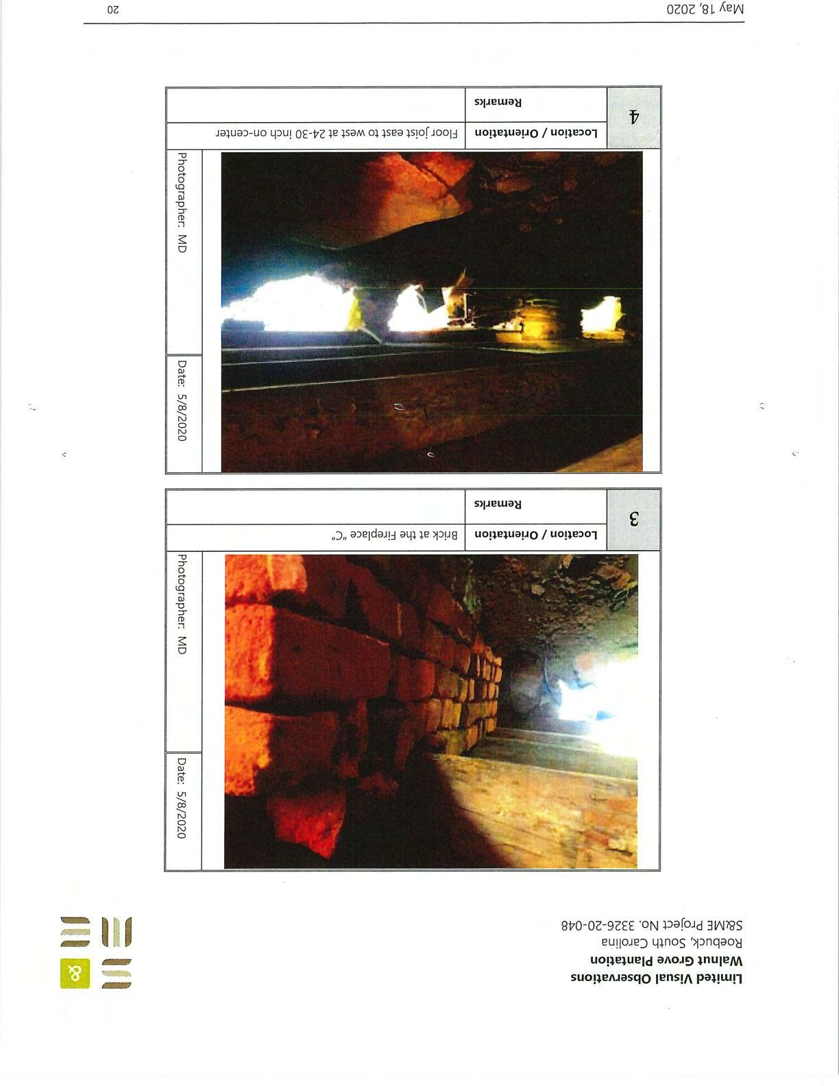
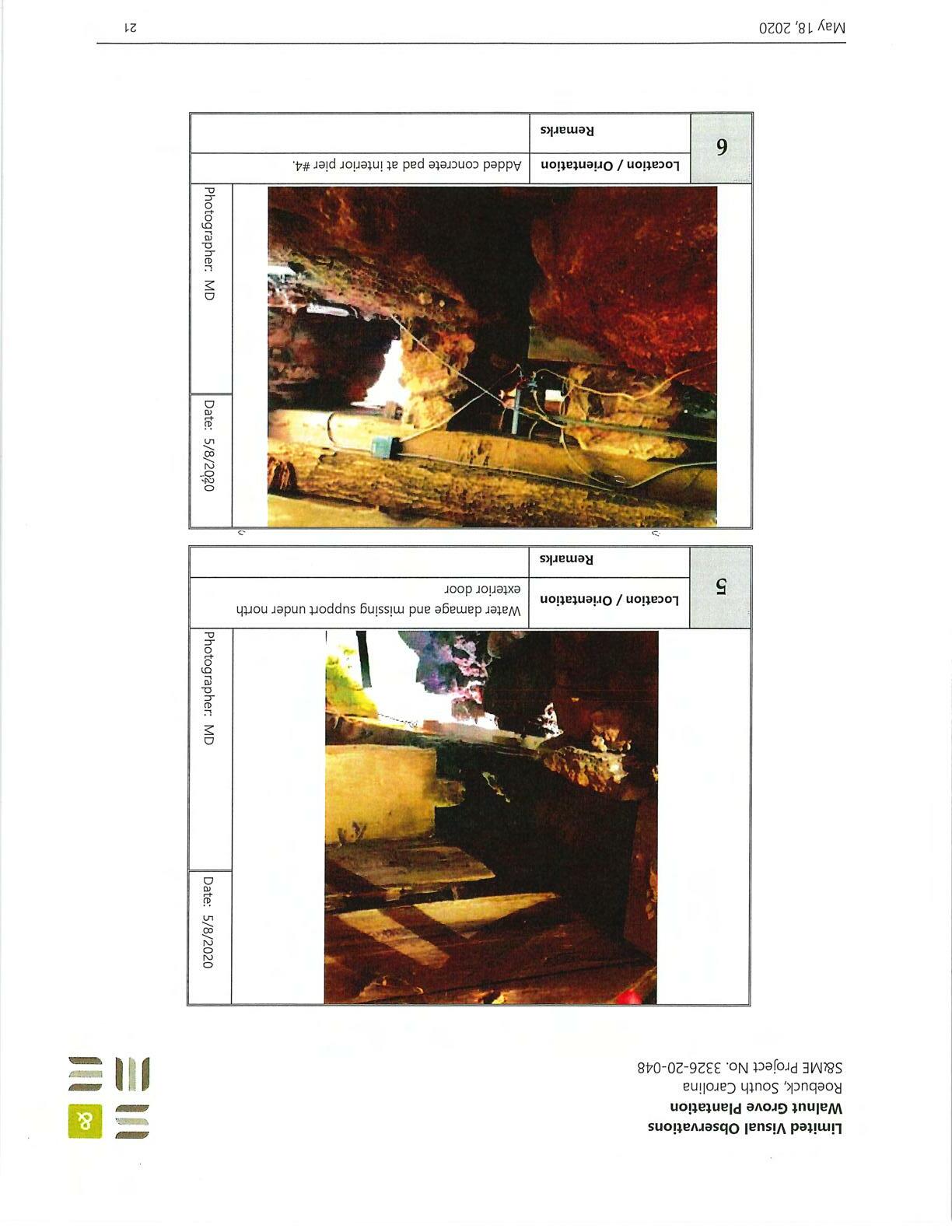


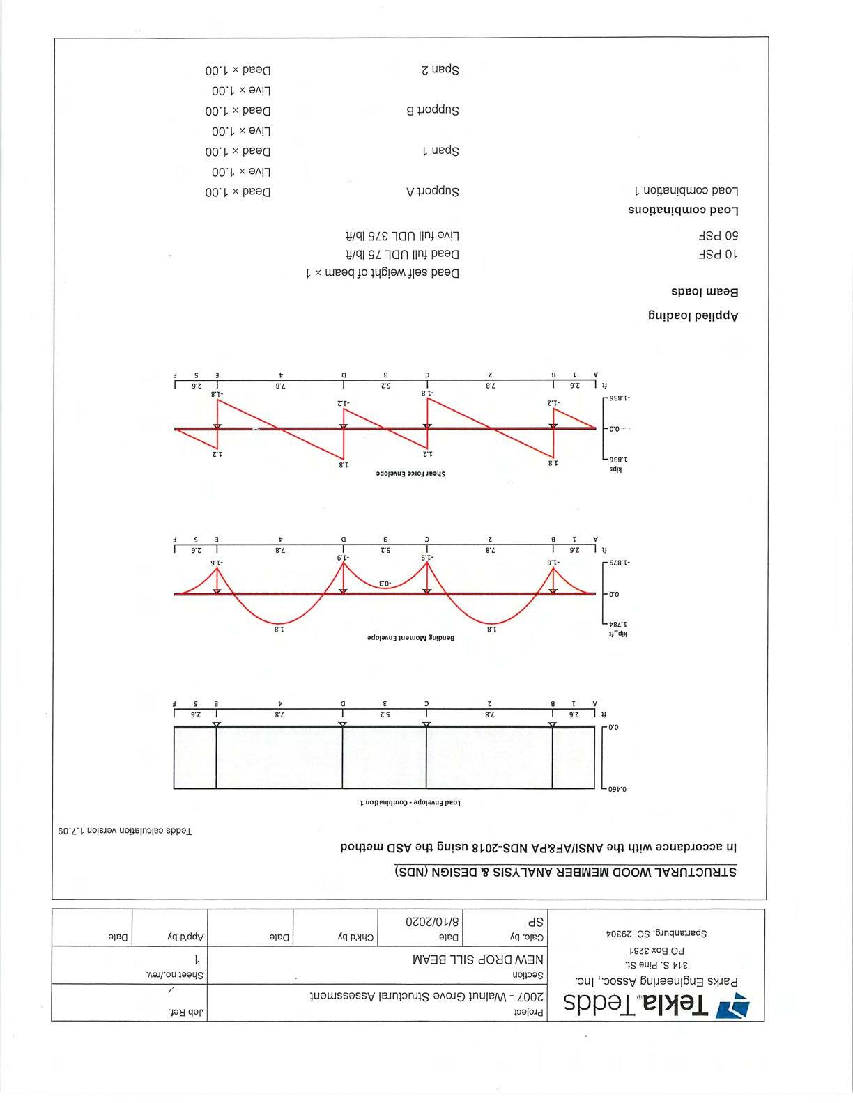

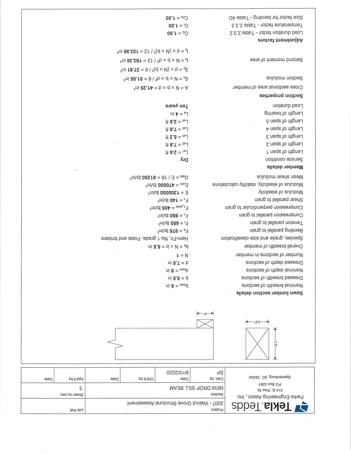
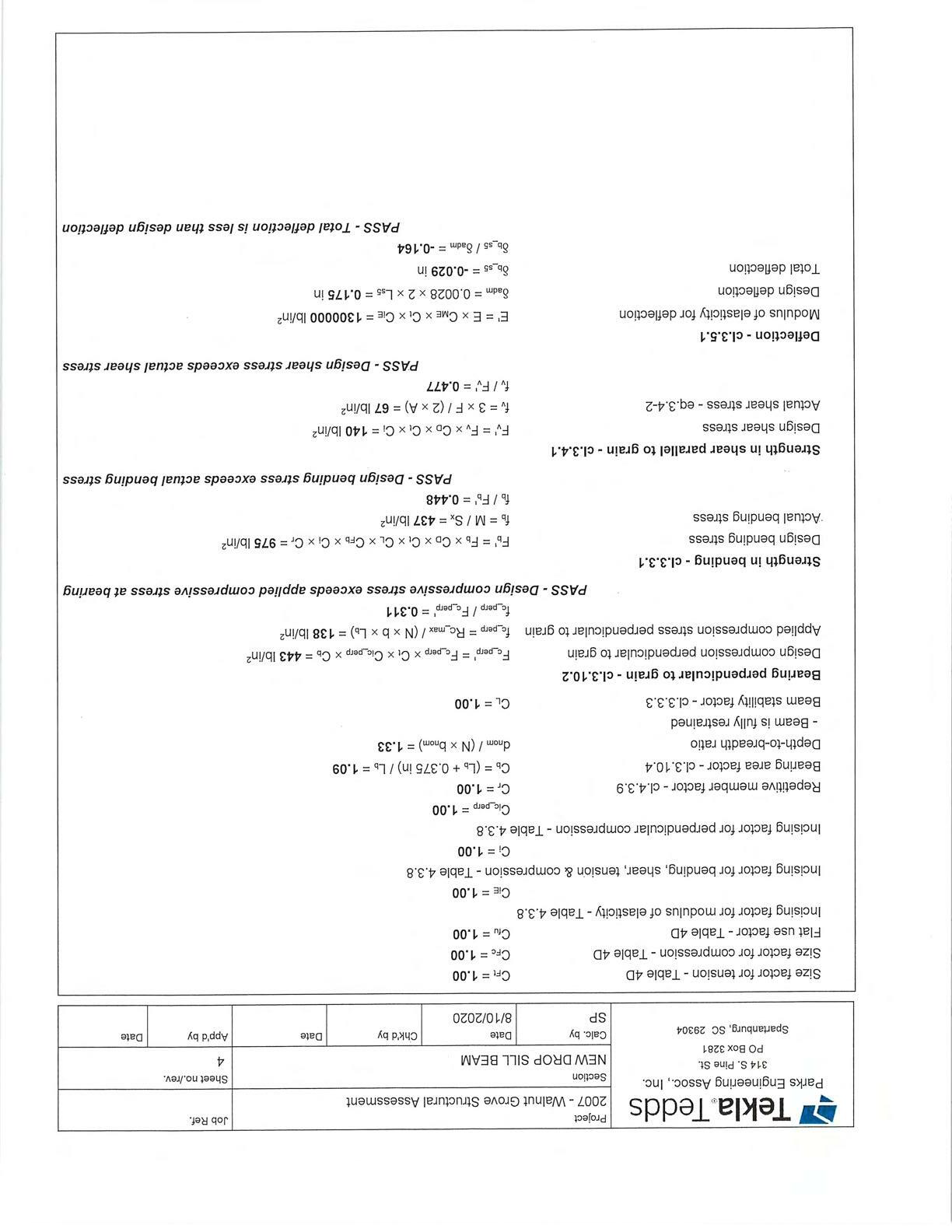
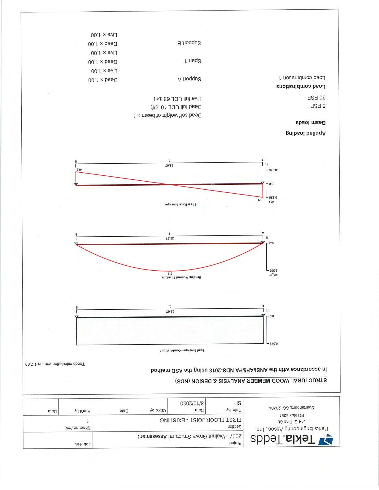
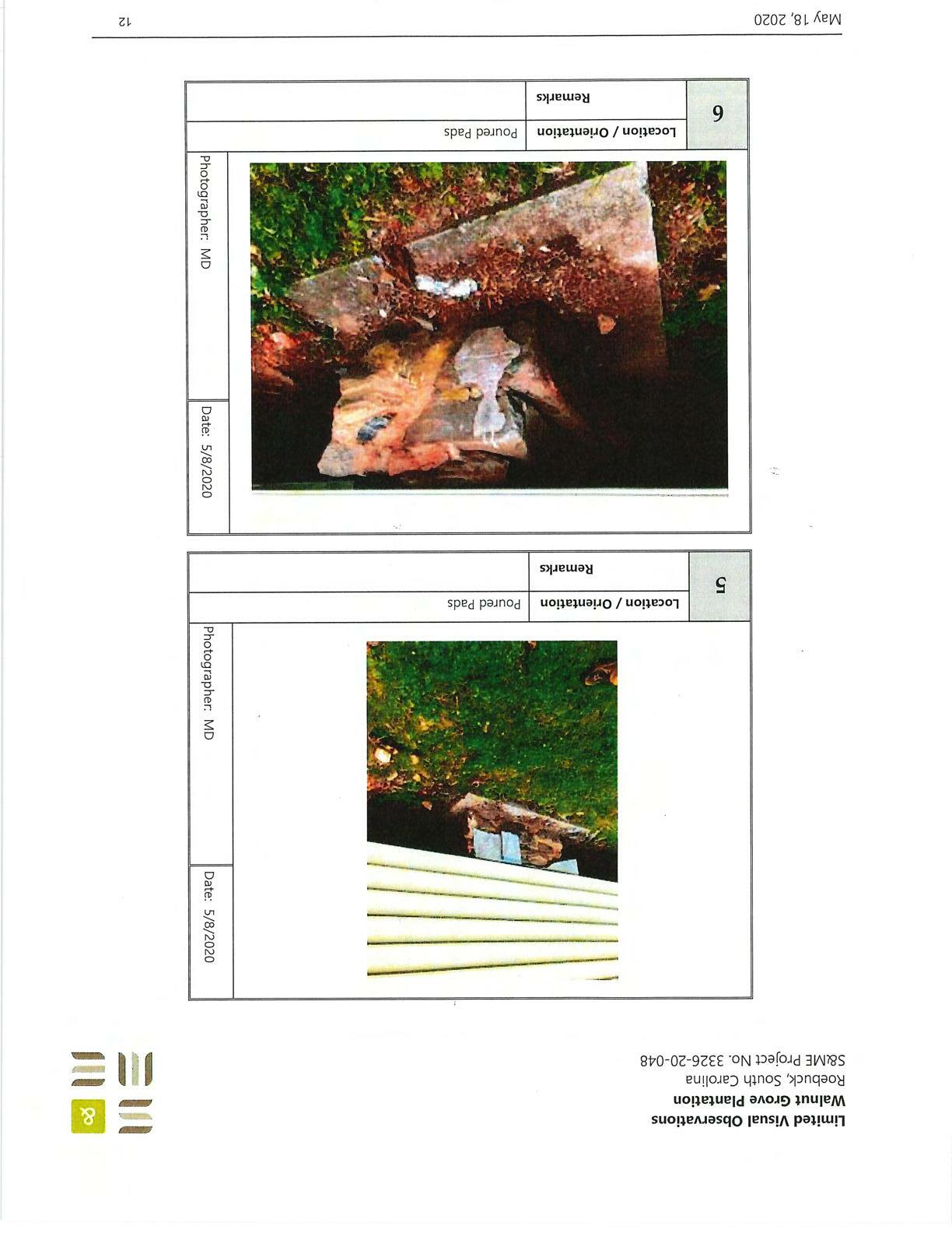


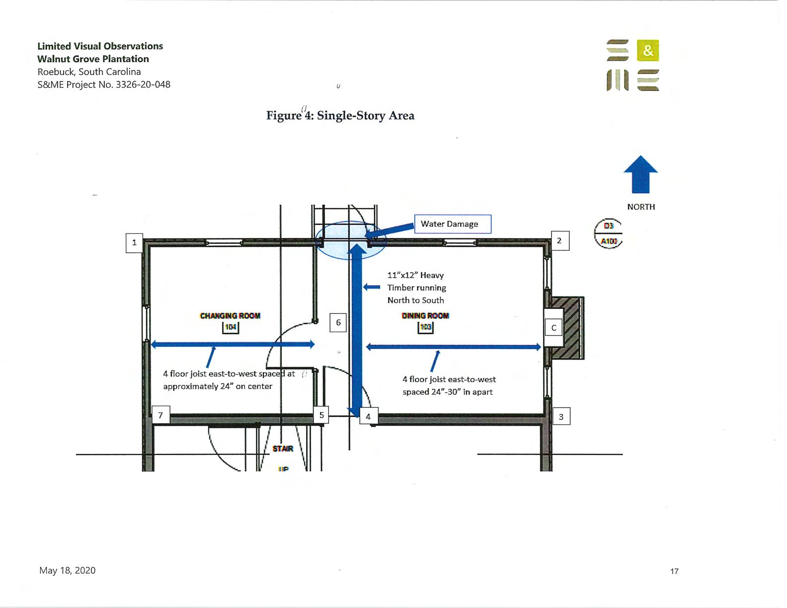


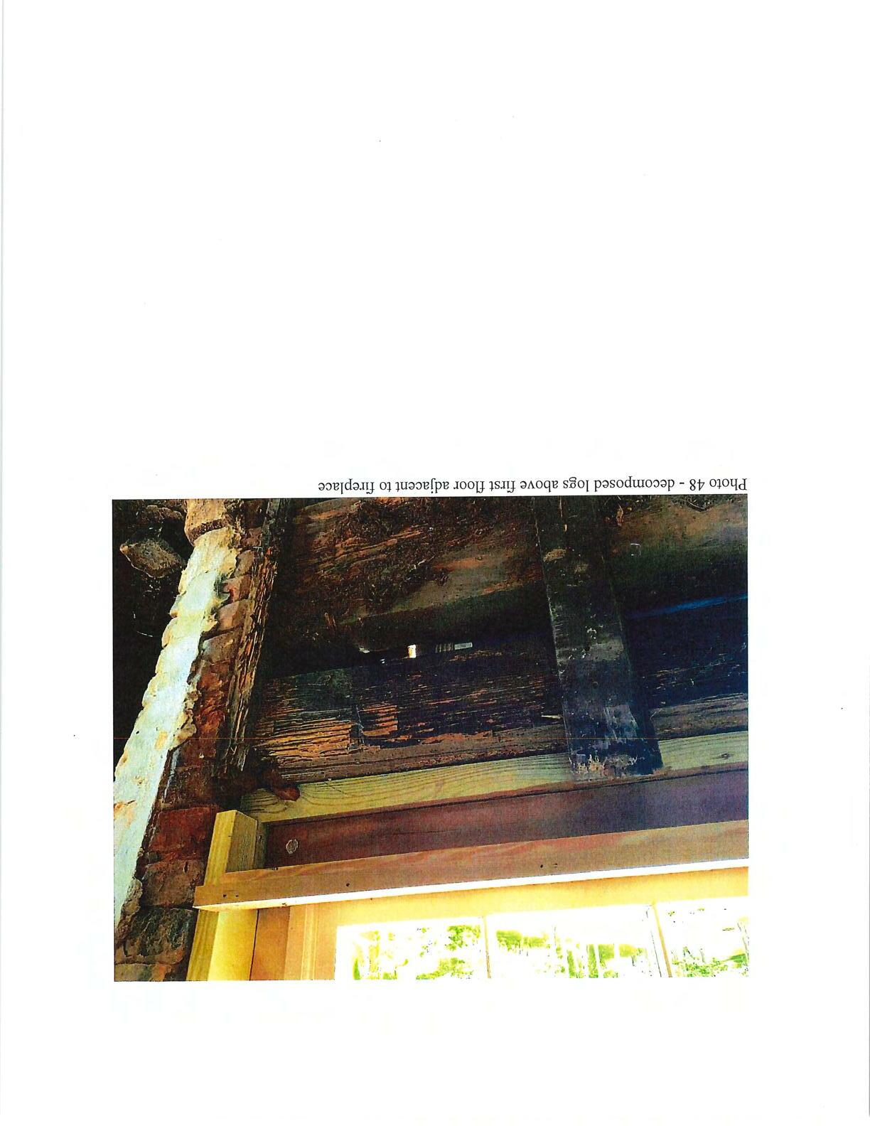

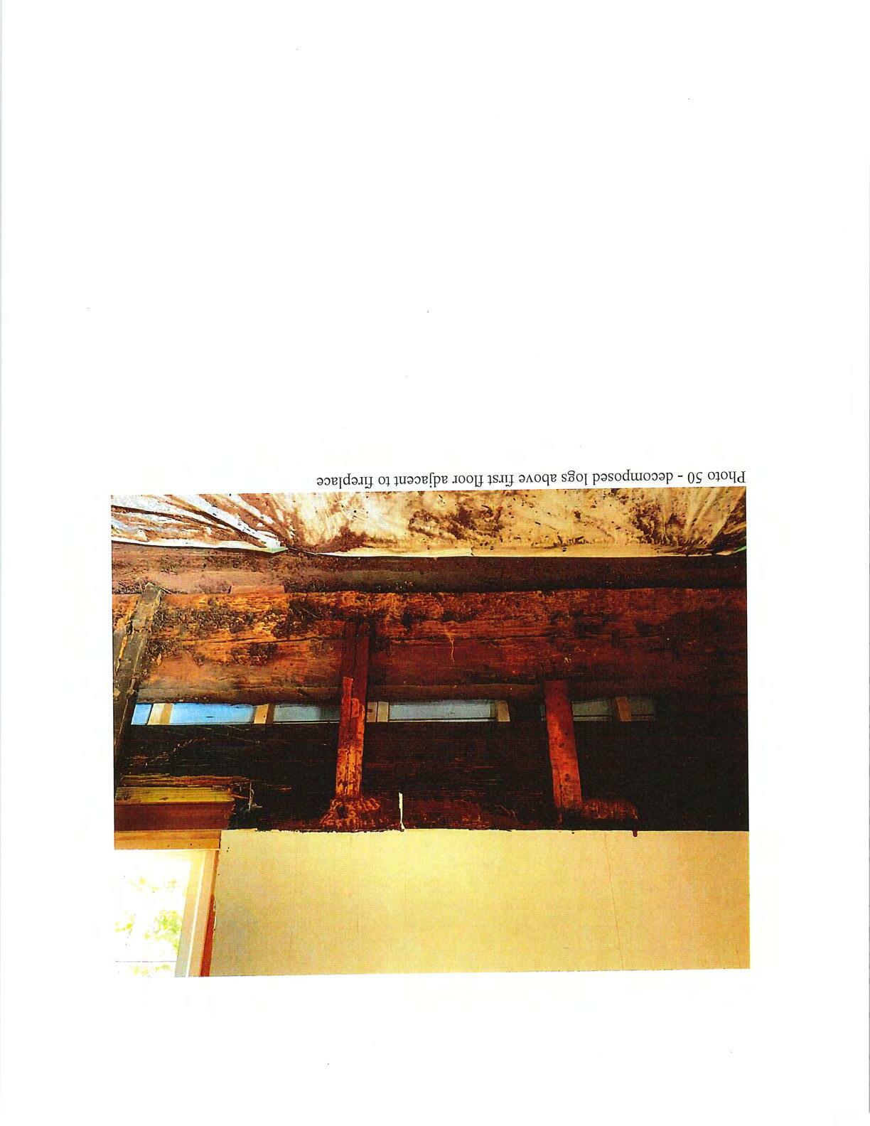

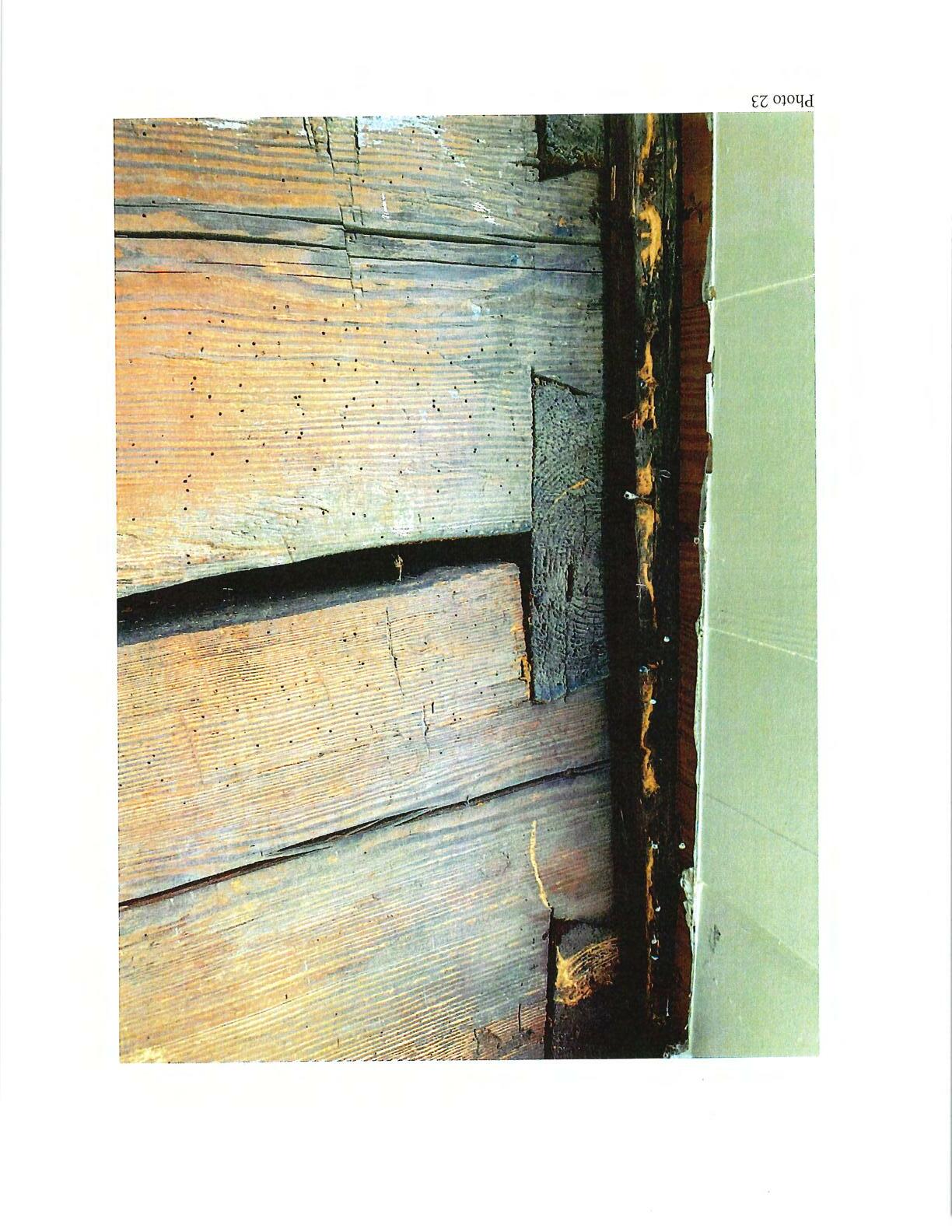
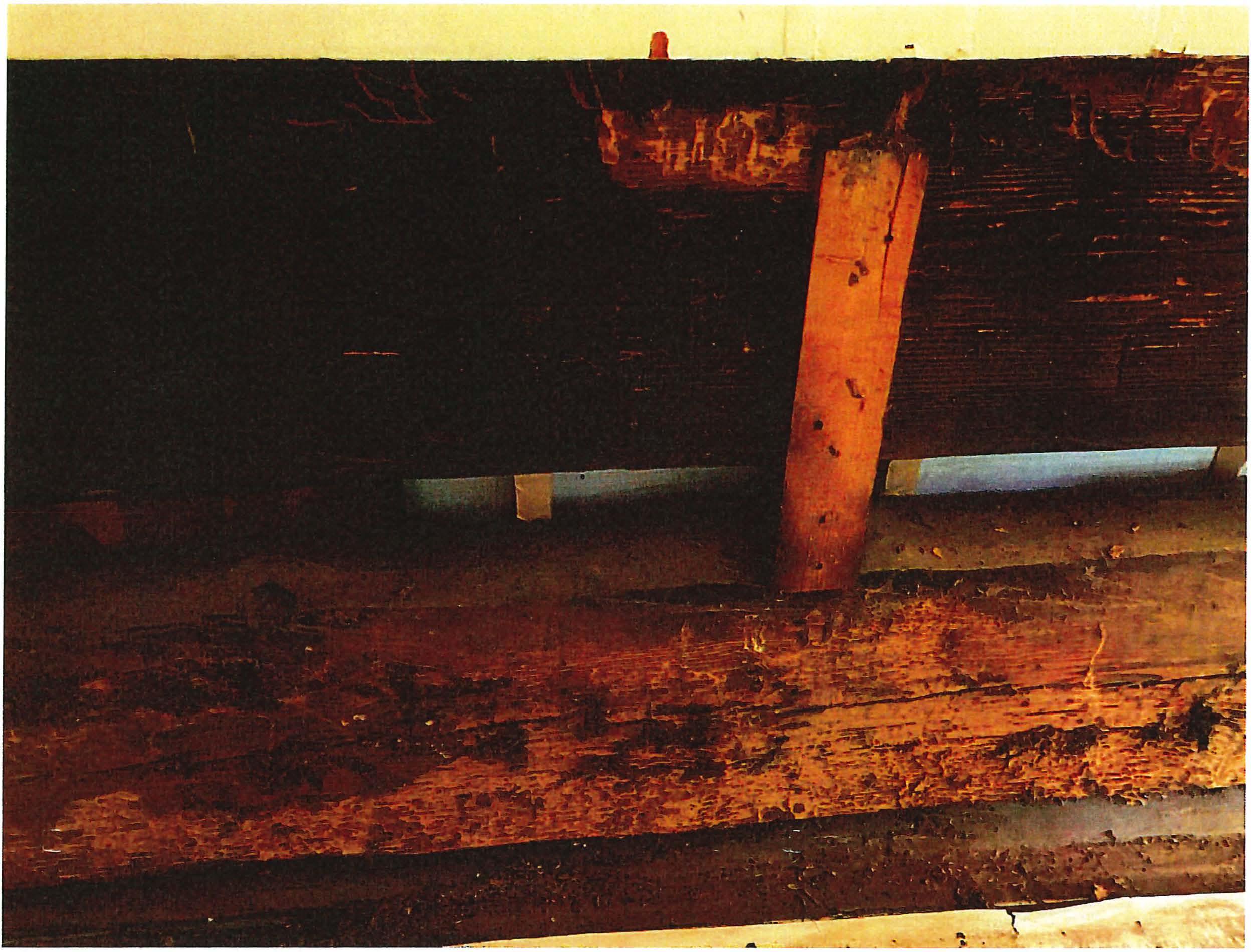 Photo 51 - decomposedlogs abovefirst floor adjacent to fireplace
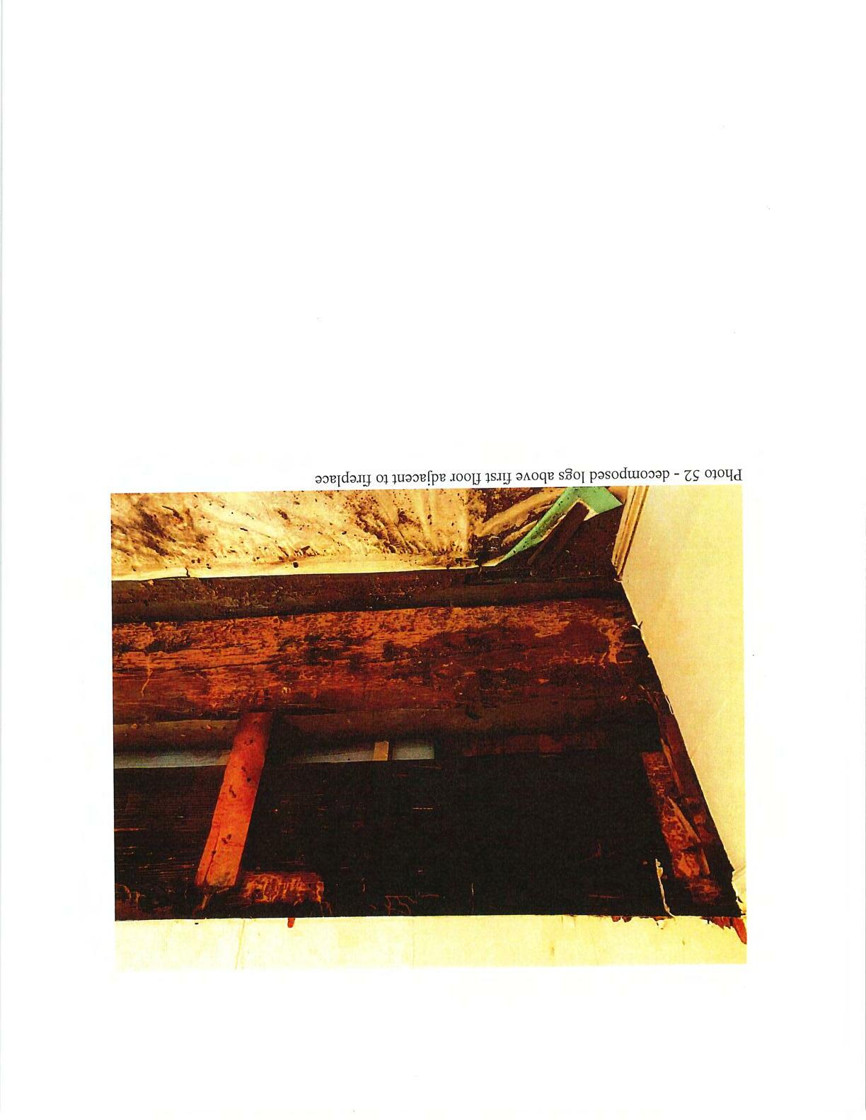
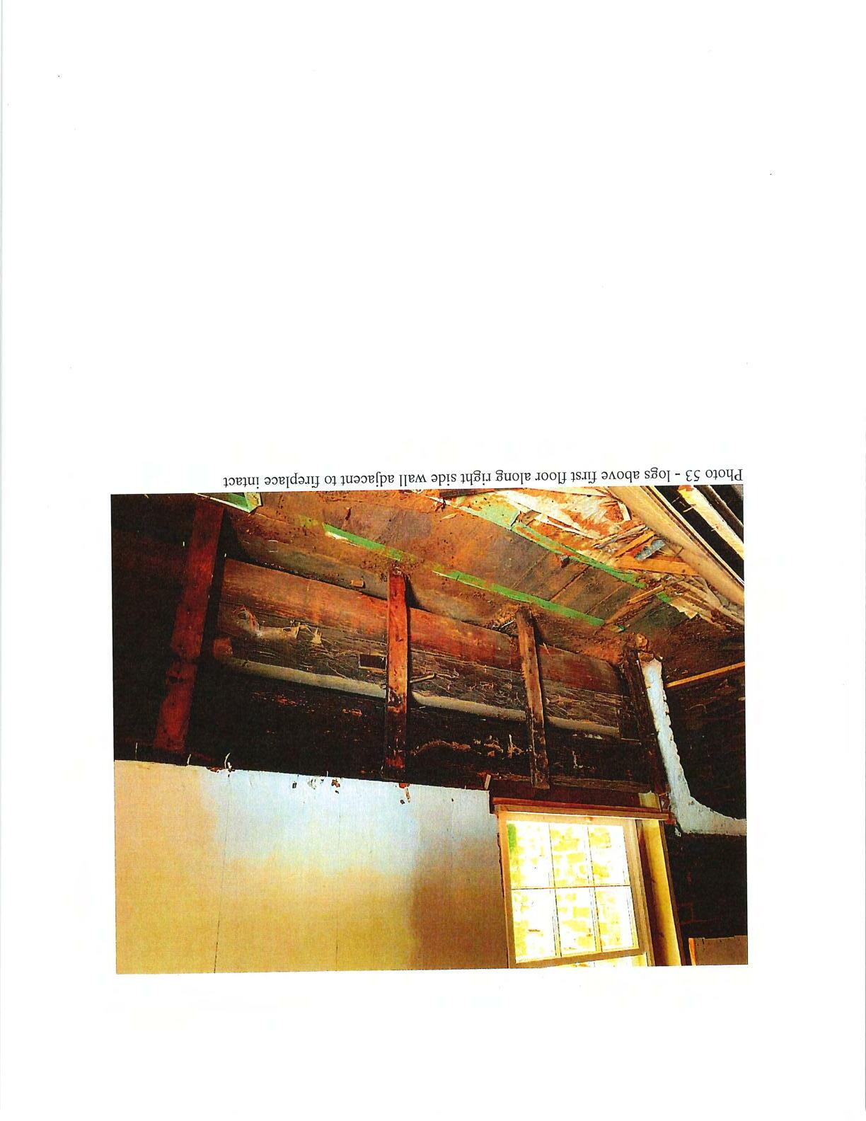
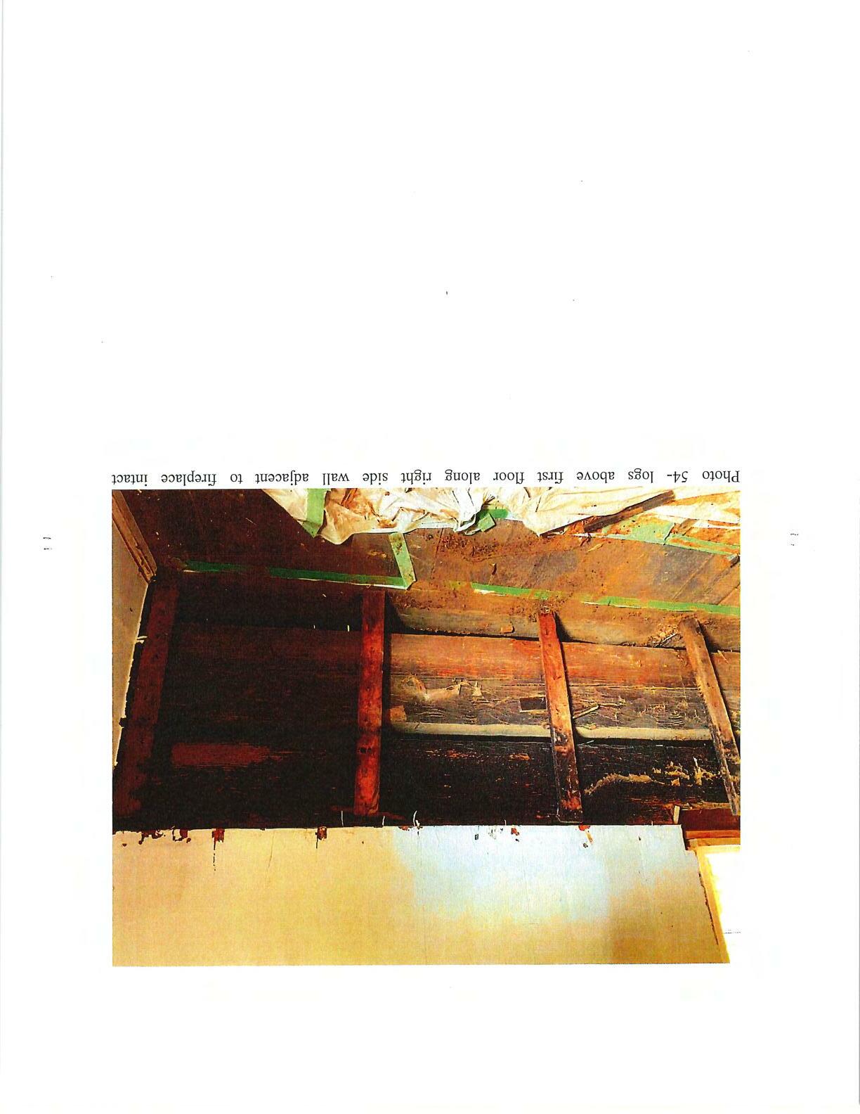

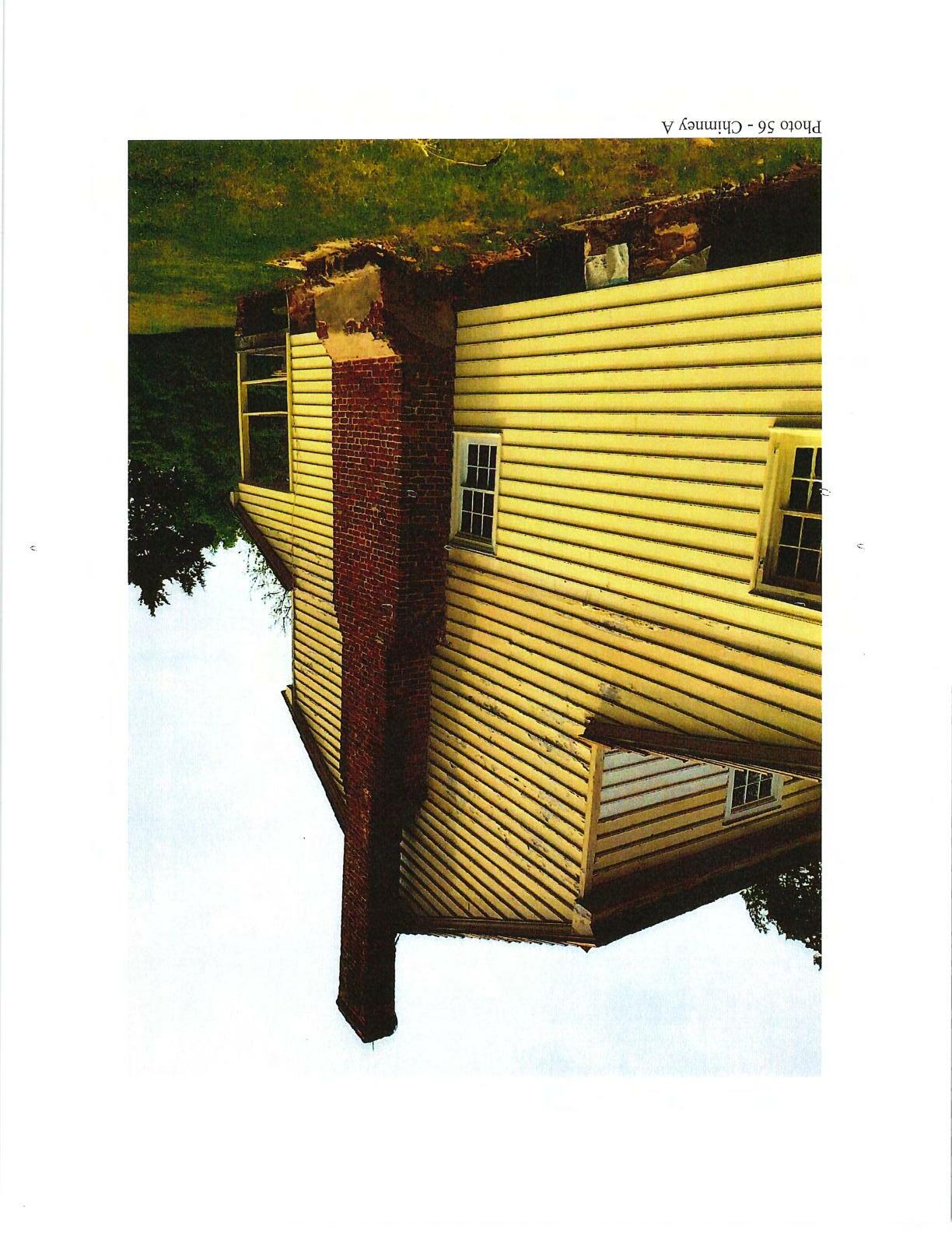
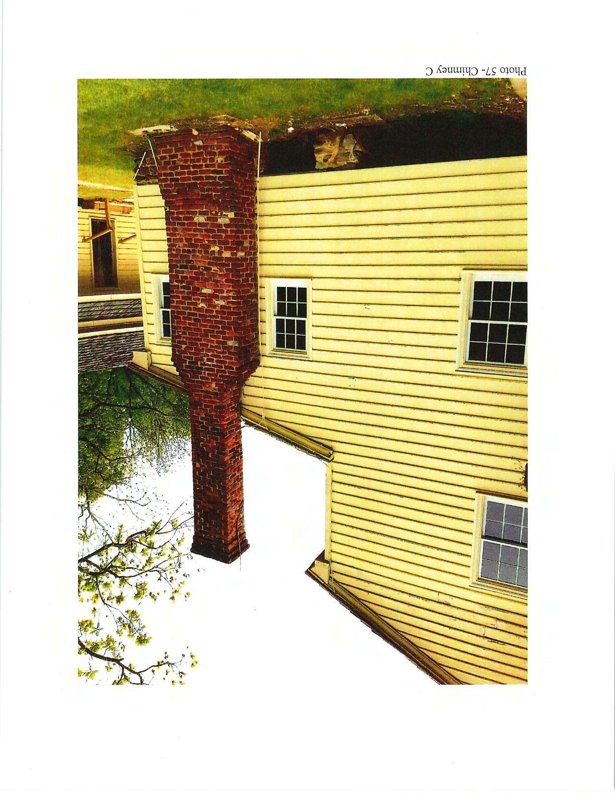
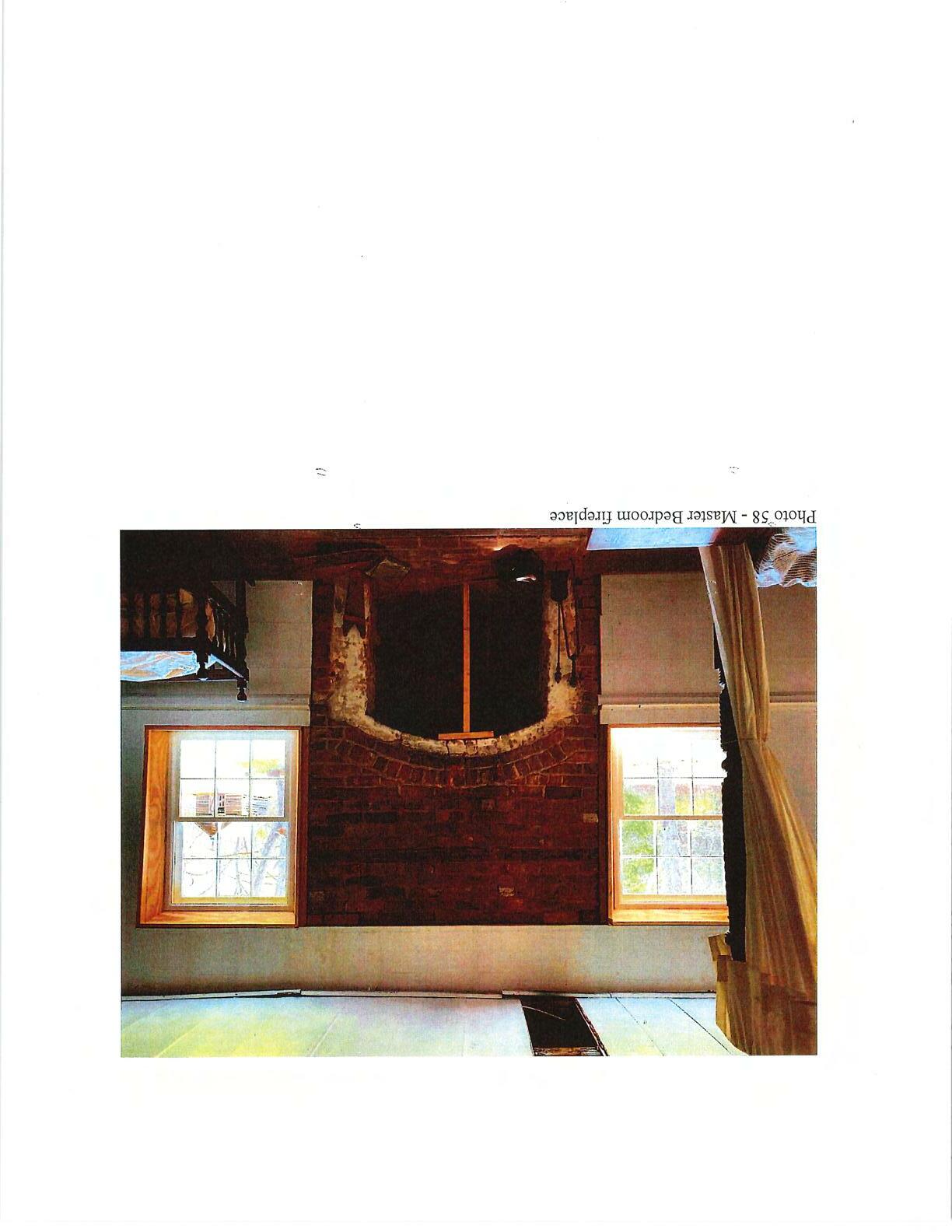
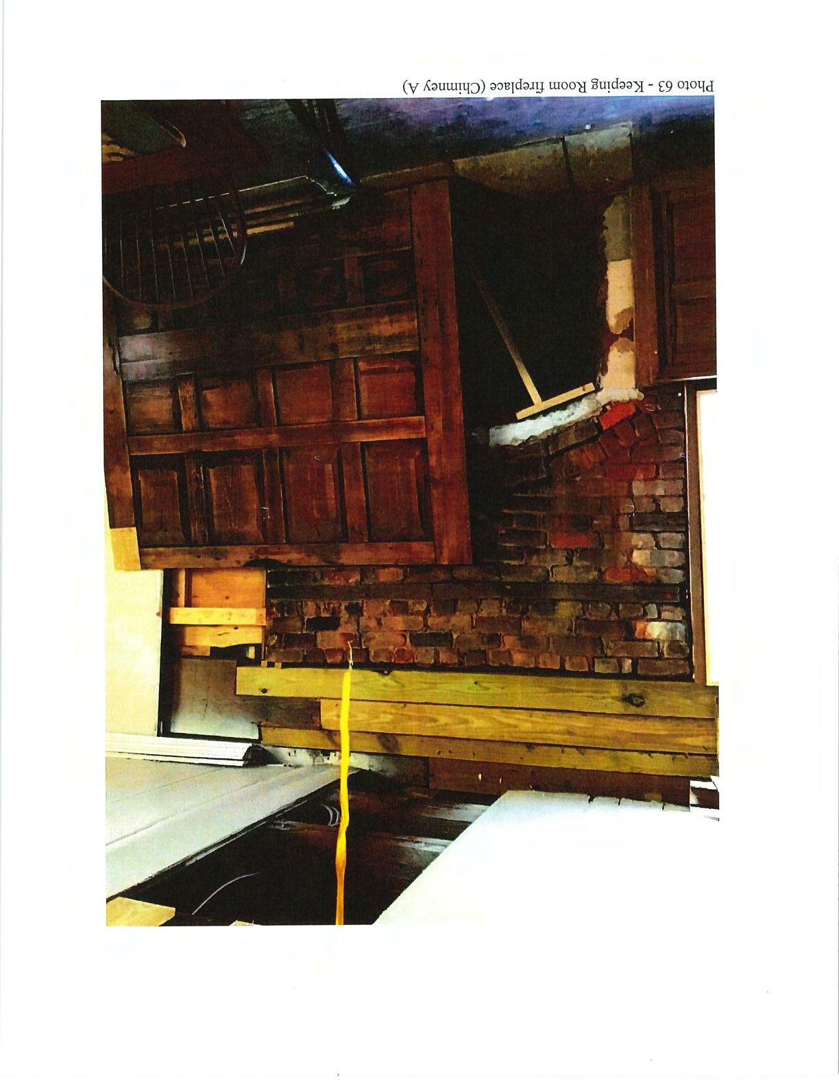

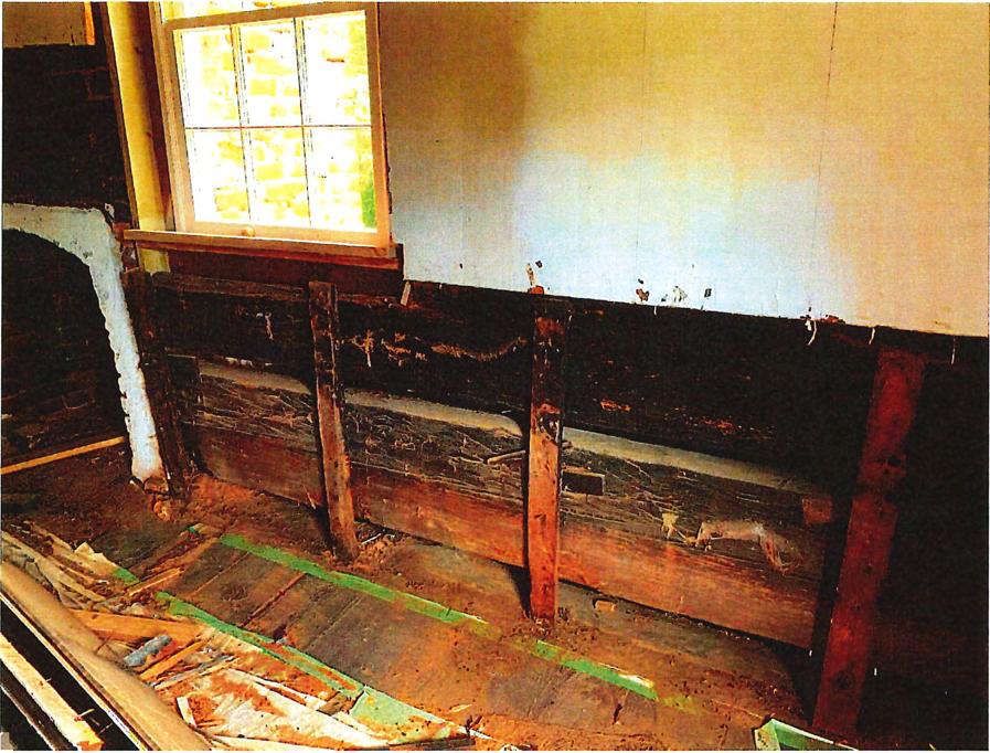
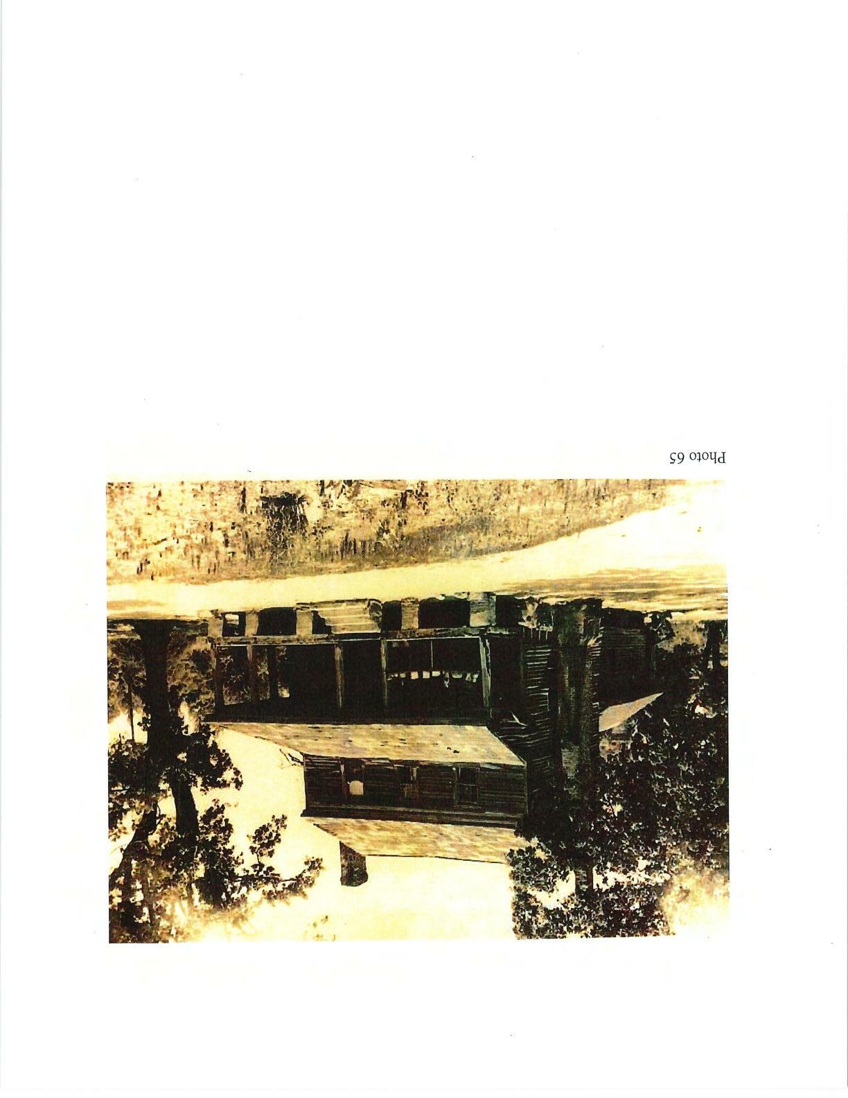


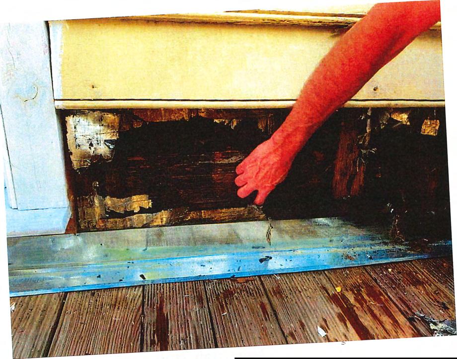 Photo28 - decomposed log atrear wall abovelowroof
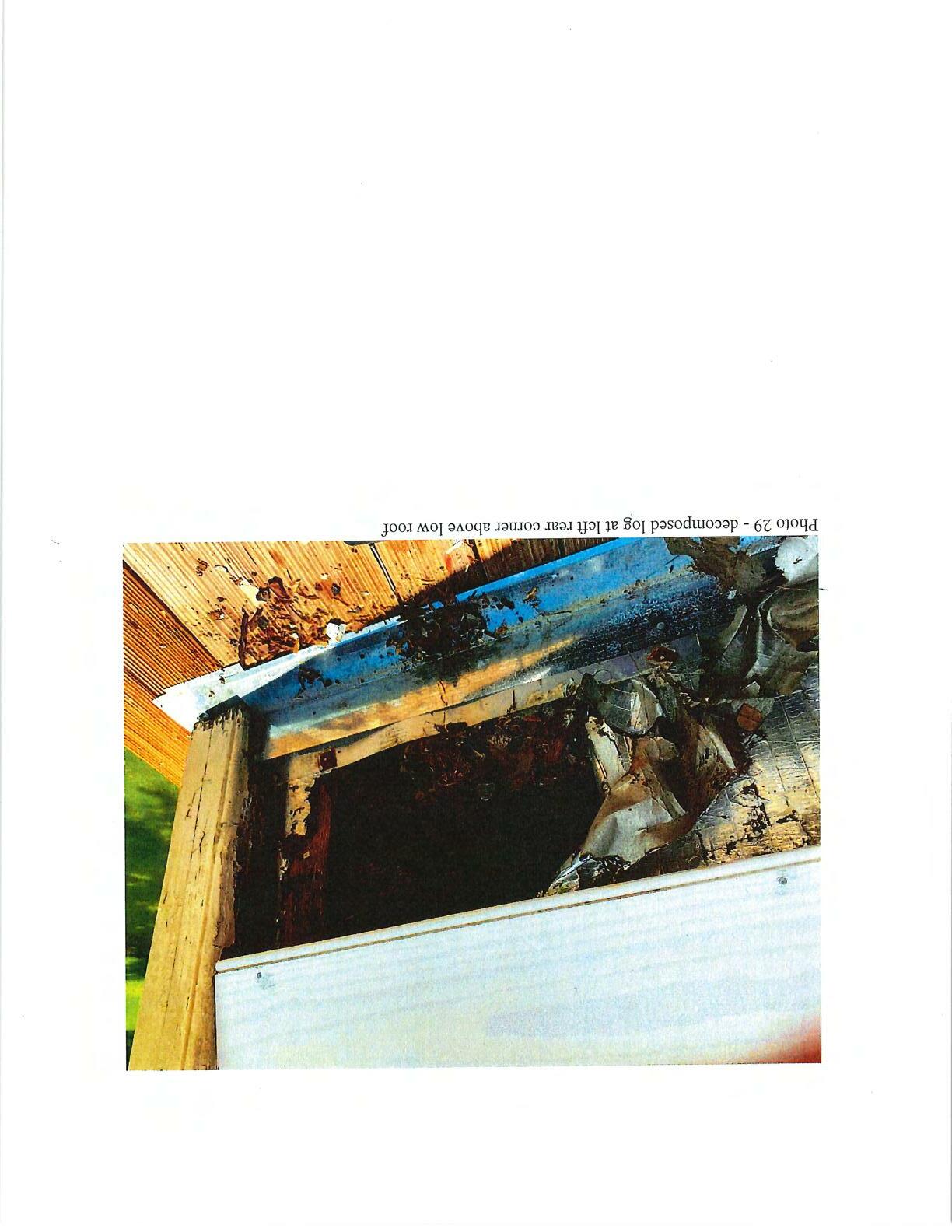
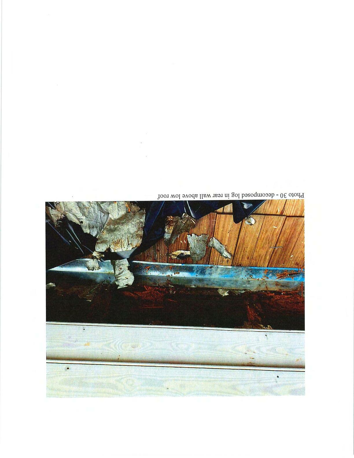
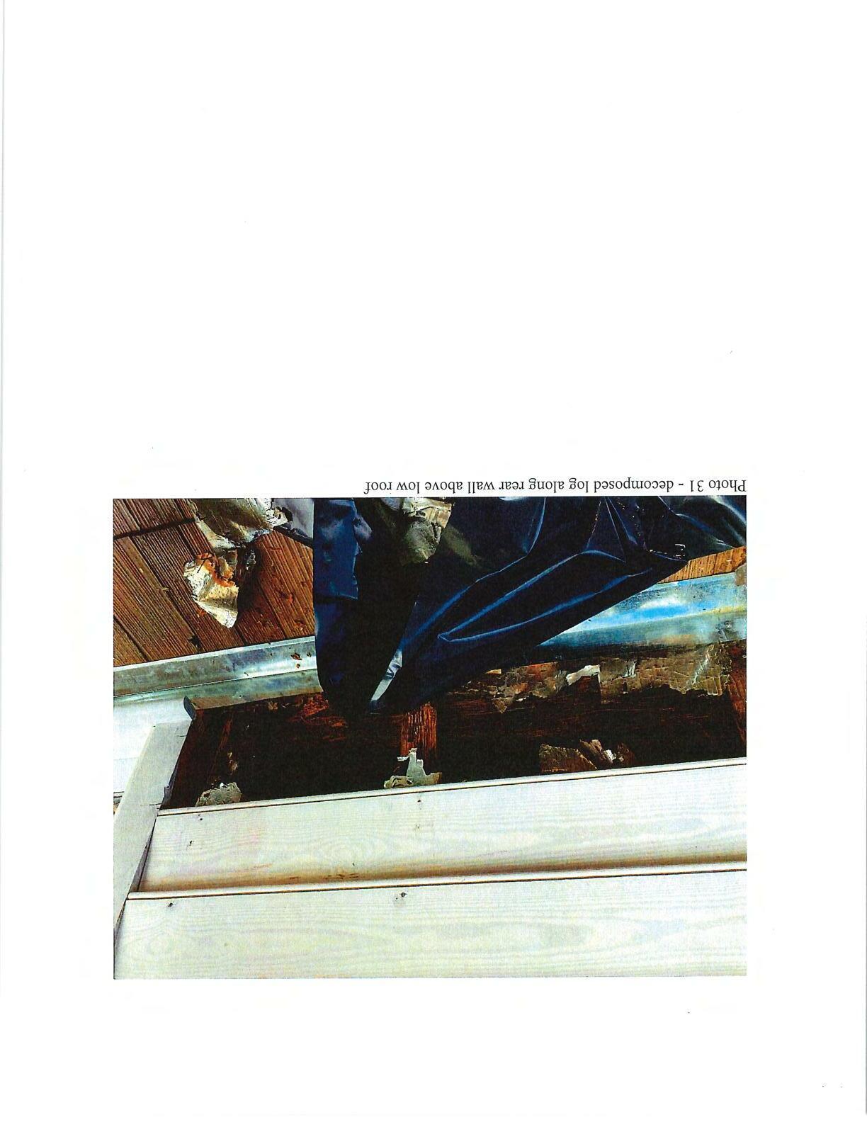
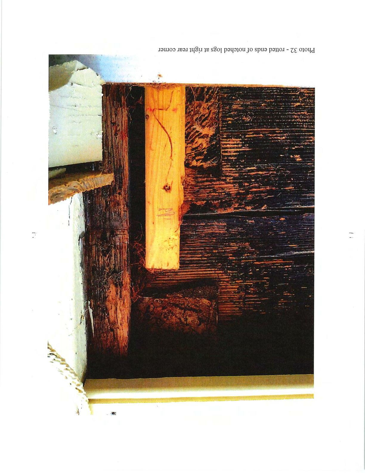
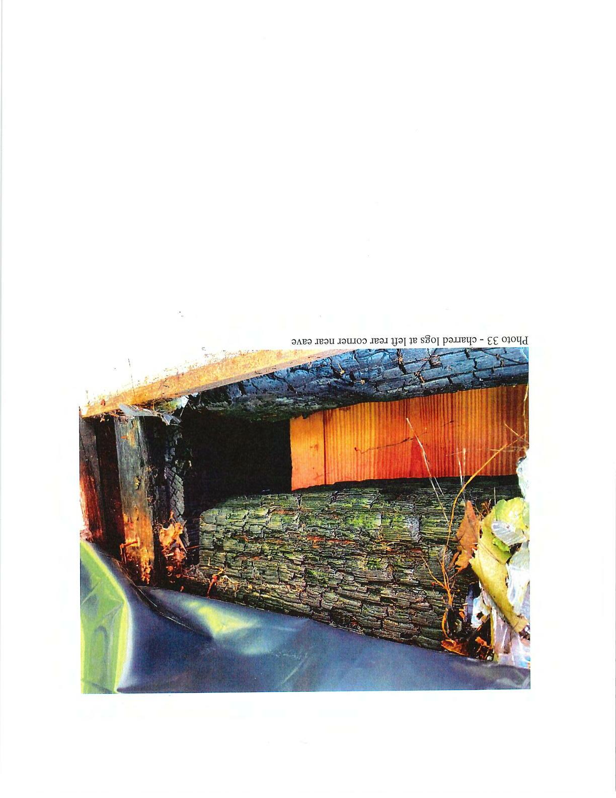

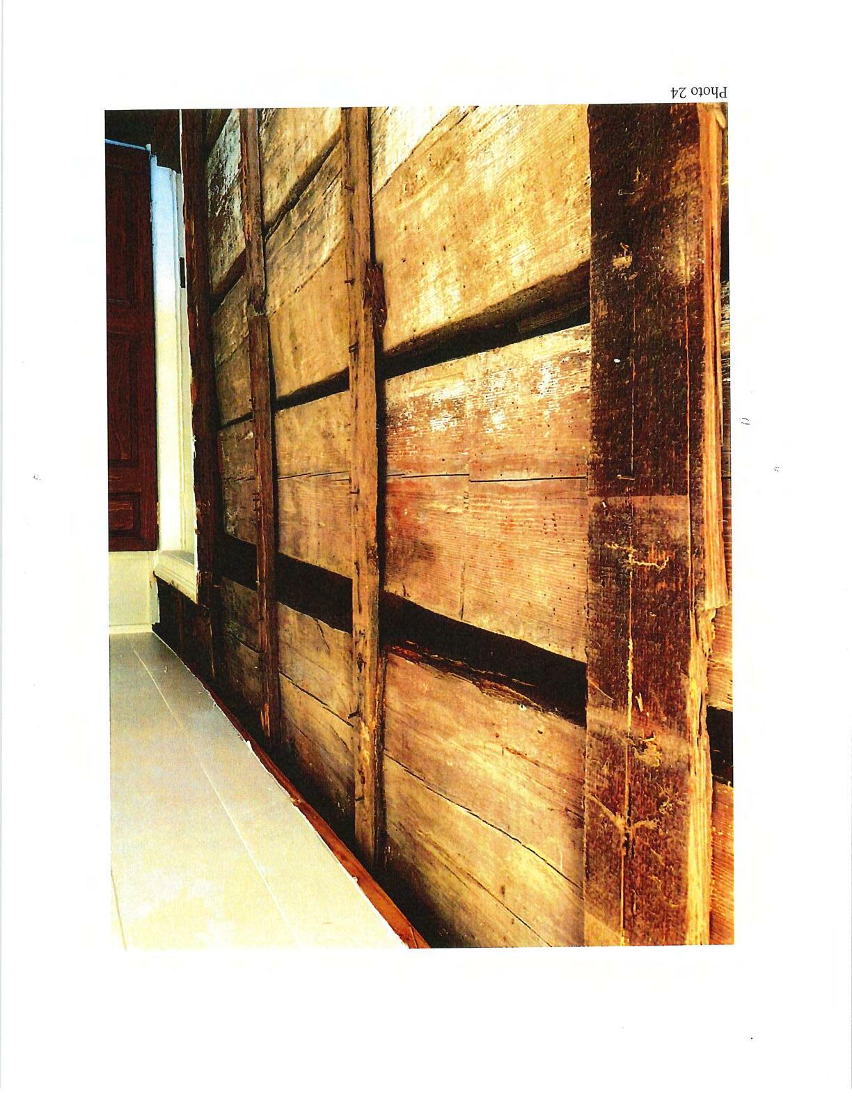
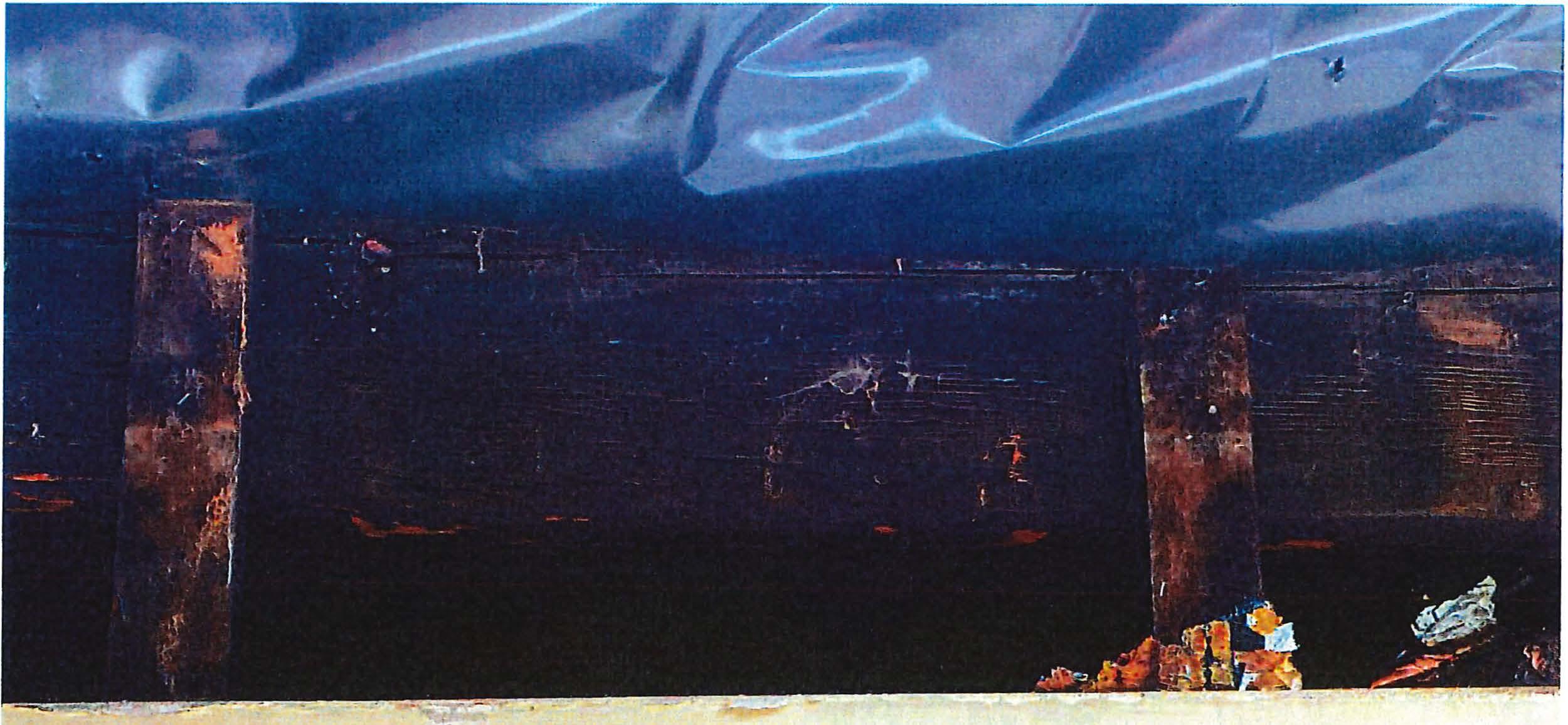 Photo 35 - log neareavealong rearwall

:,I___,,
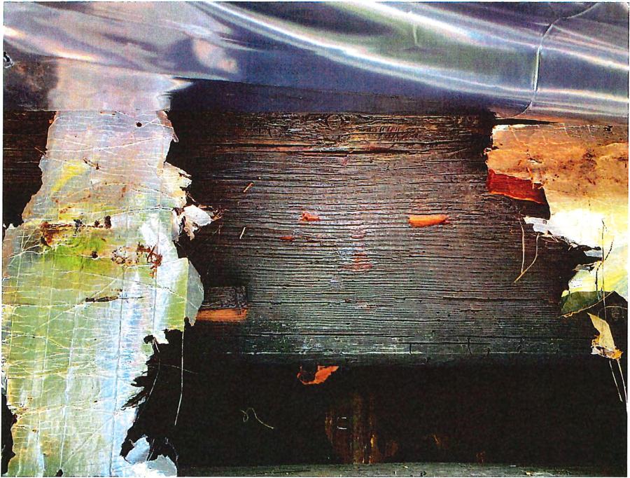
 Photo 39 - log neareave alongrearwall

 Photo40 - decomposed log along firstfloor atrightsidewall

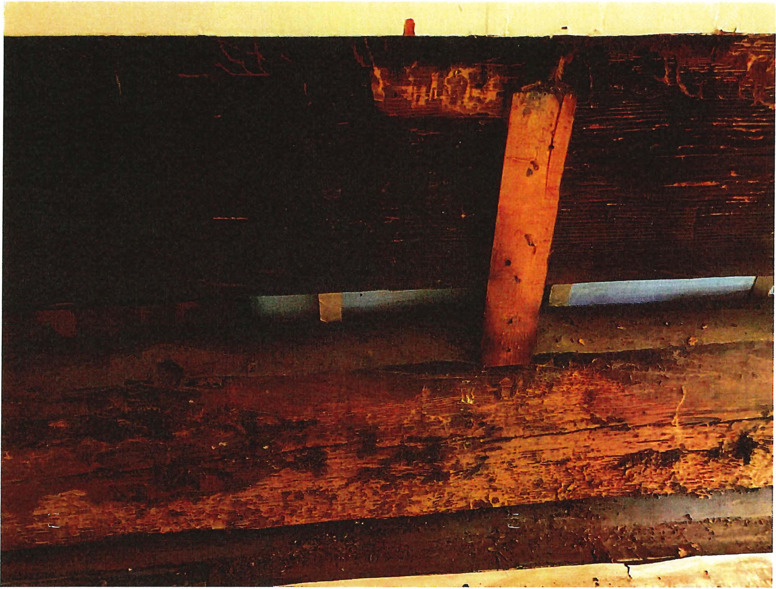 Photo41 - decomposed log alongfirstfloor atrightsidewall

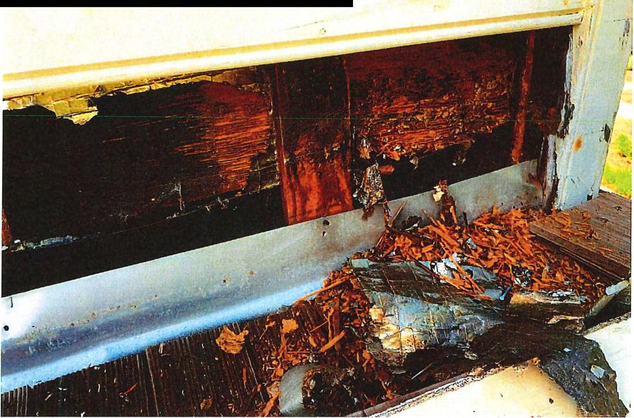
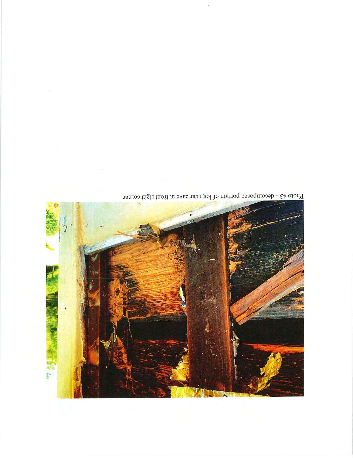
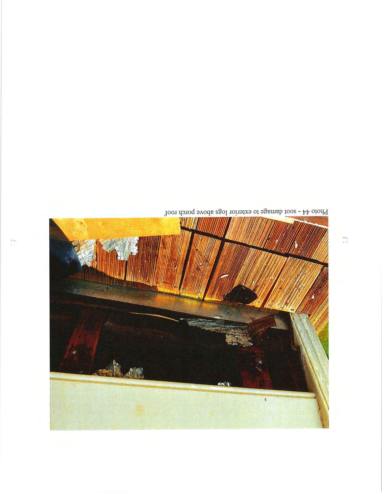

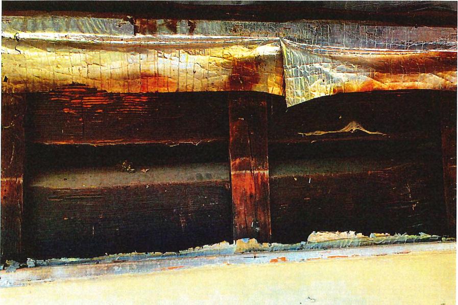

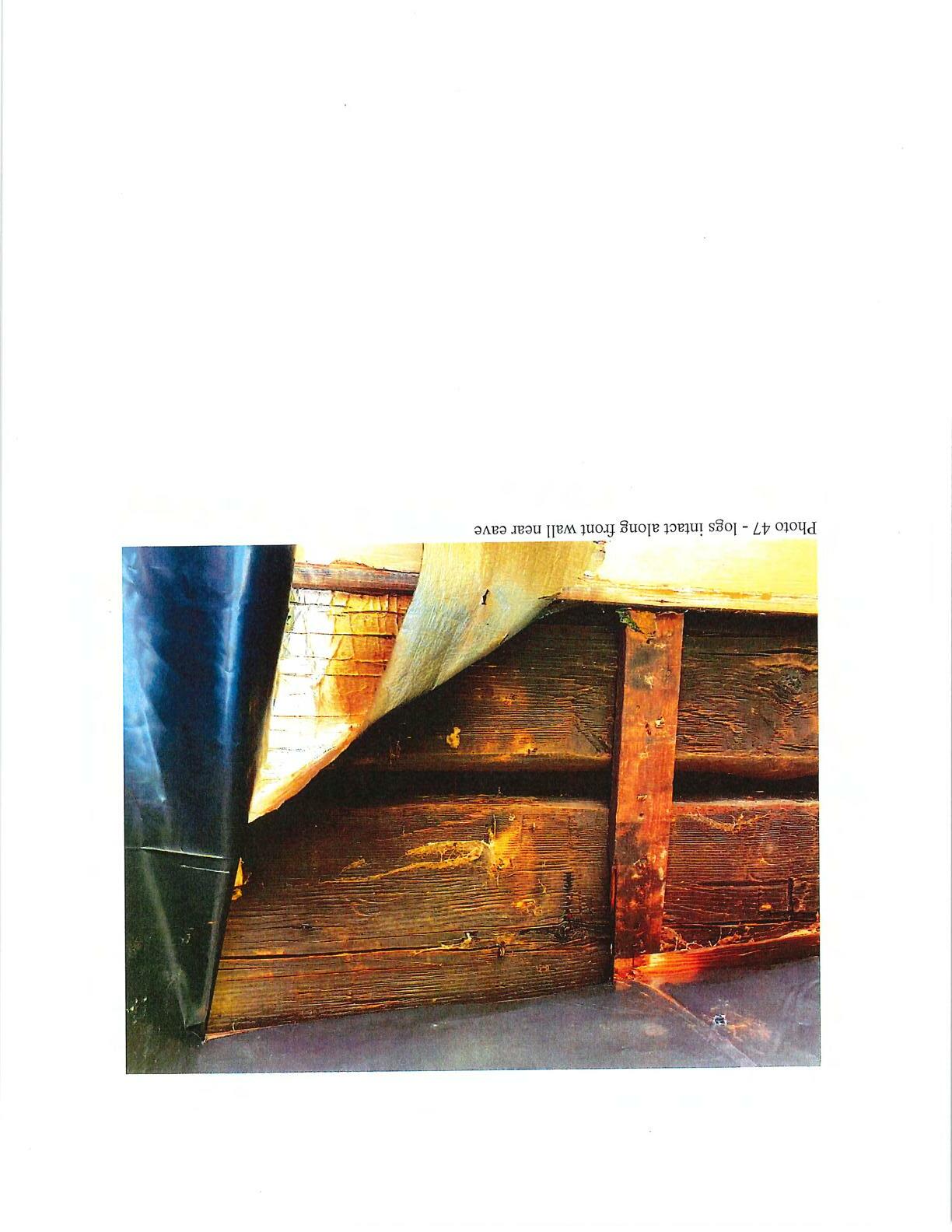
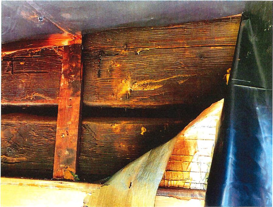 Photo47 - logs intact along frontwallneareave

 Photo28 - decomposedlogatrearwallabovelowroof


 Photo 35 - log neareavealong rearwall
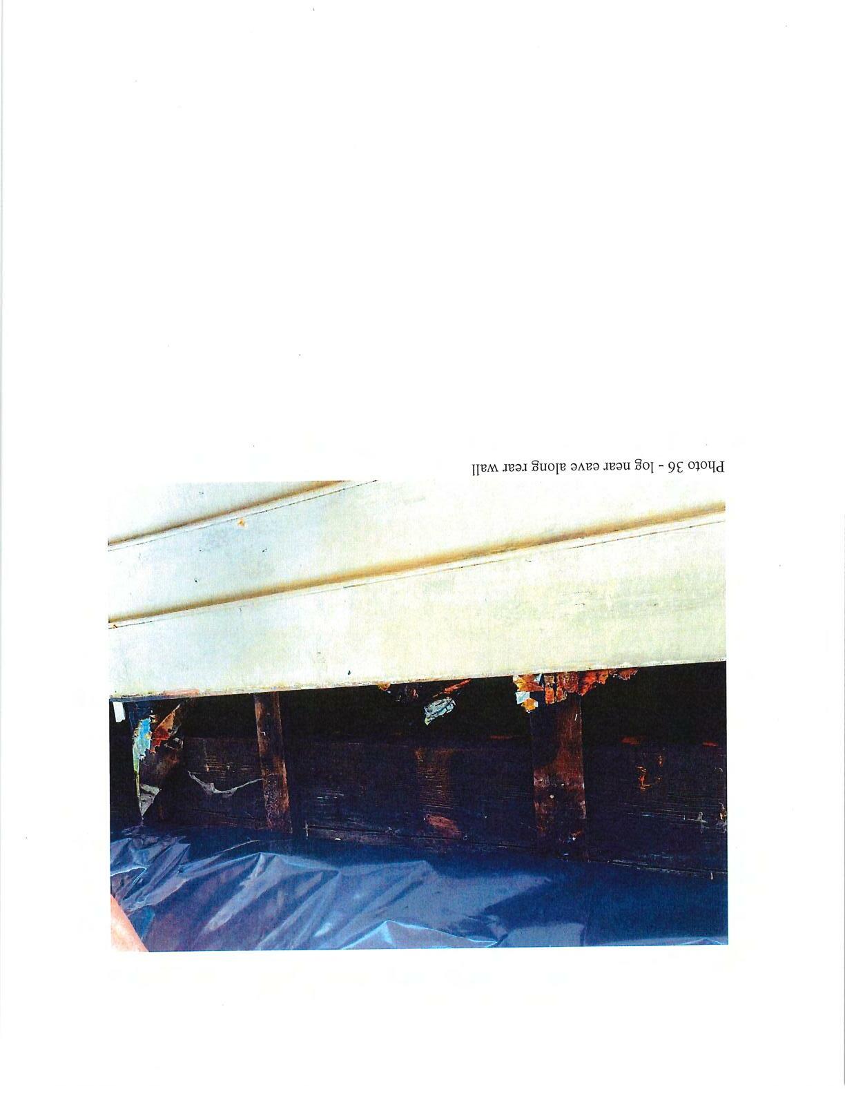
Photo36- logneareave alongrearwall

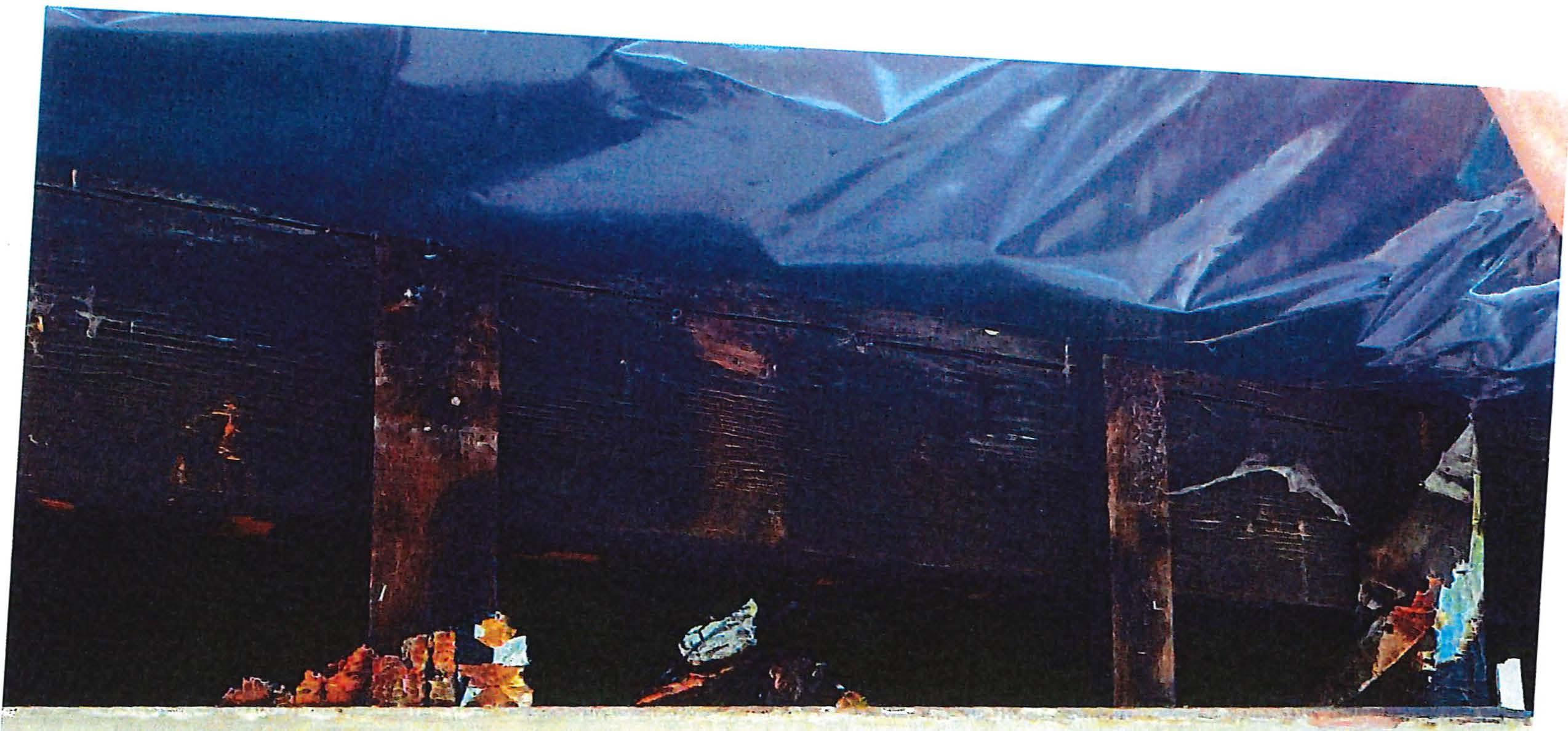


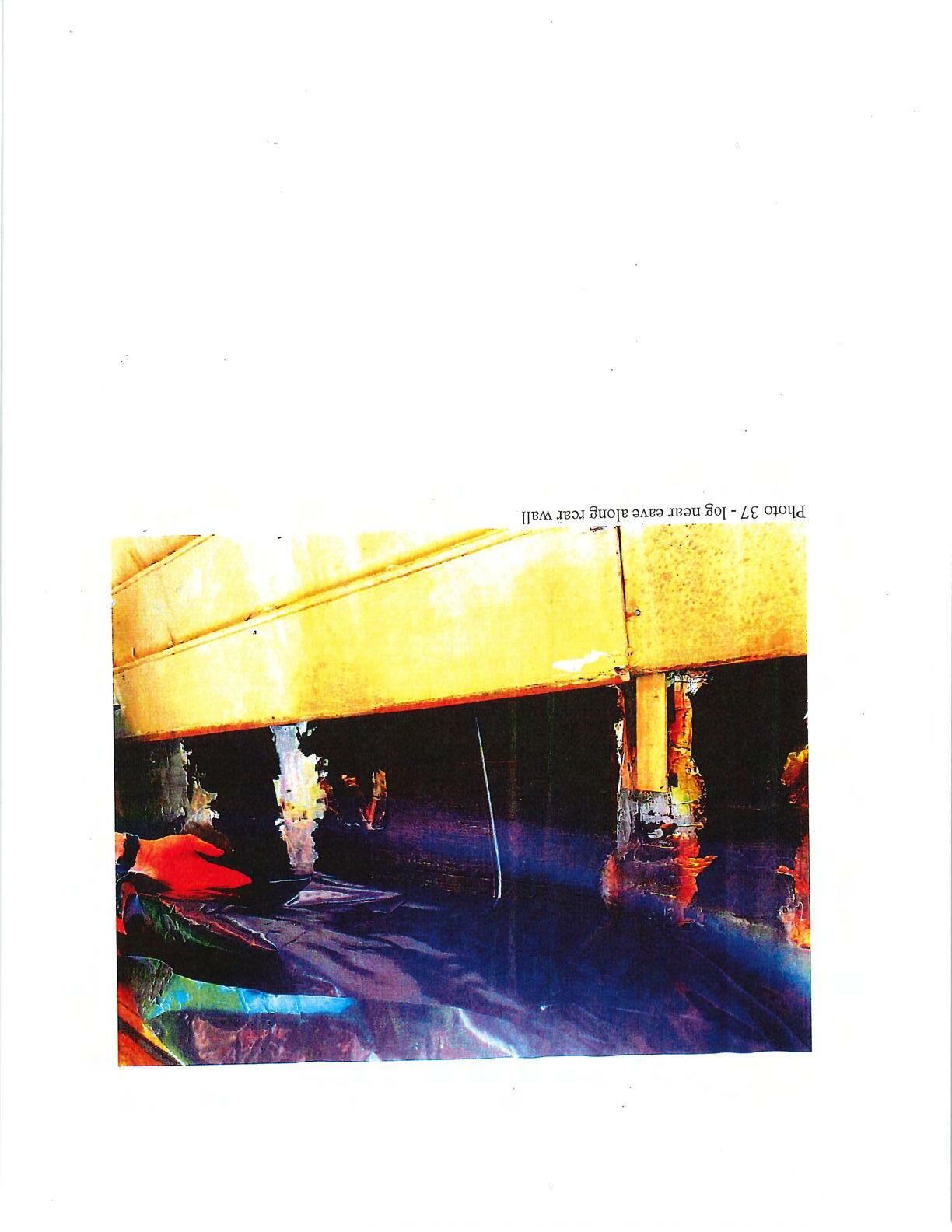
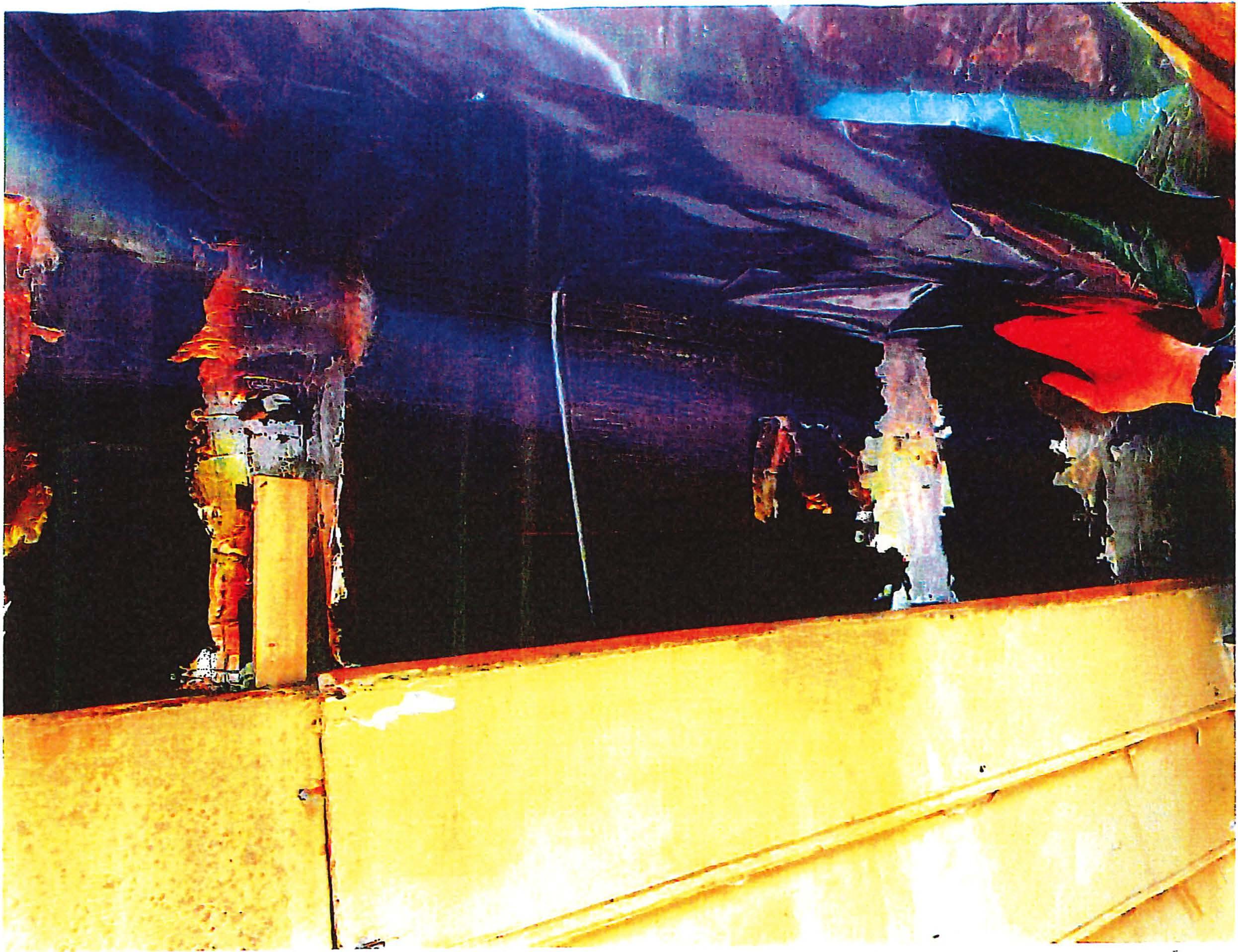 Photo 37 -logneareavealongrearwall

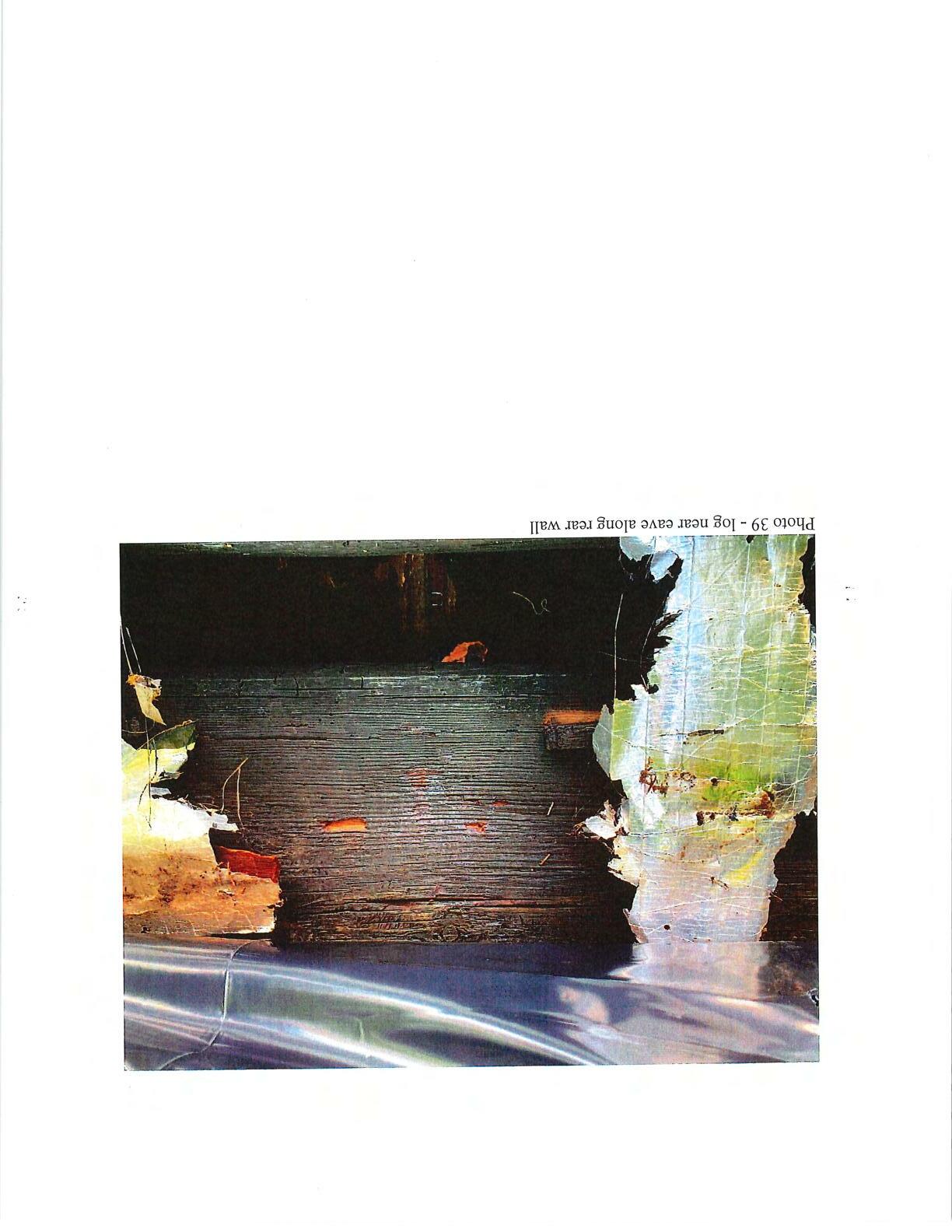
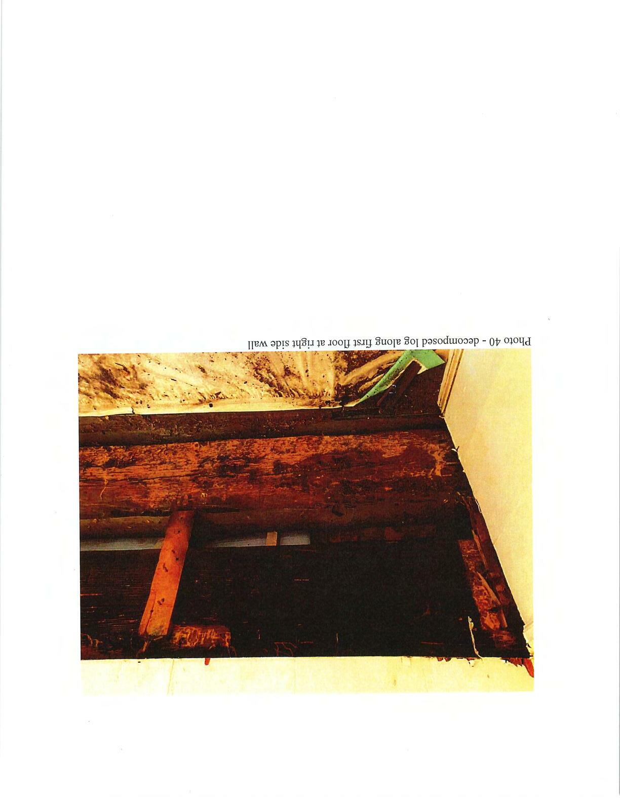
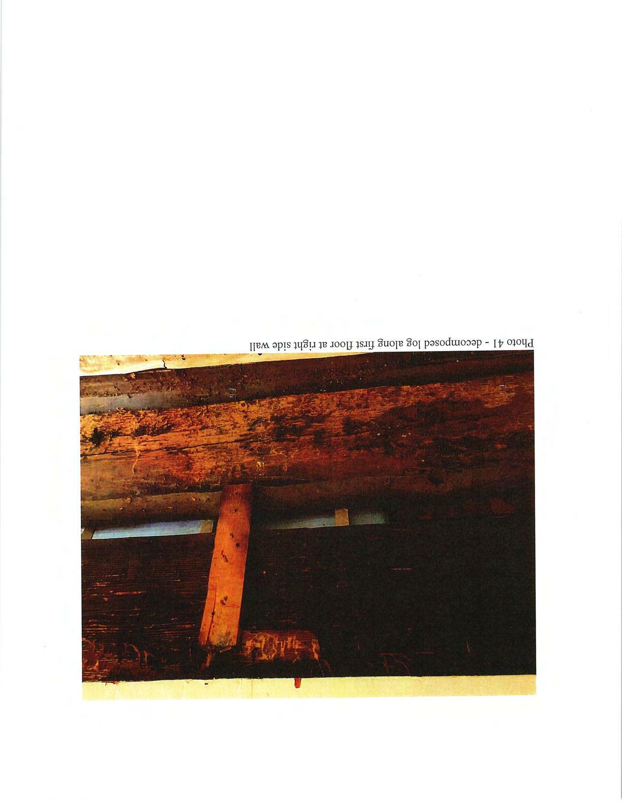



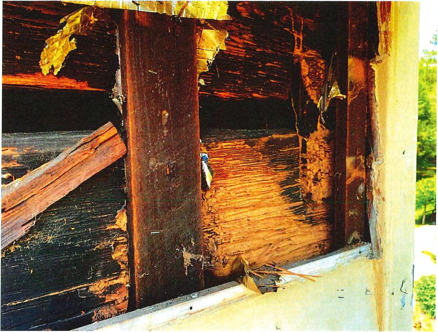 Photo43 - decomposedportion oflog neareaveatfrontrightcorner

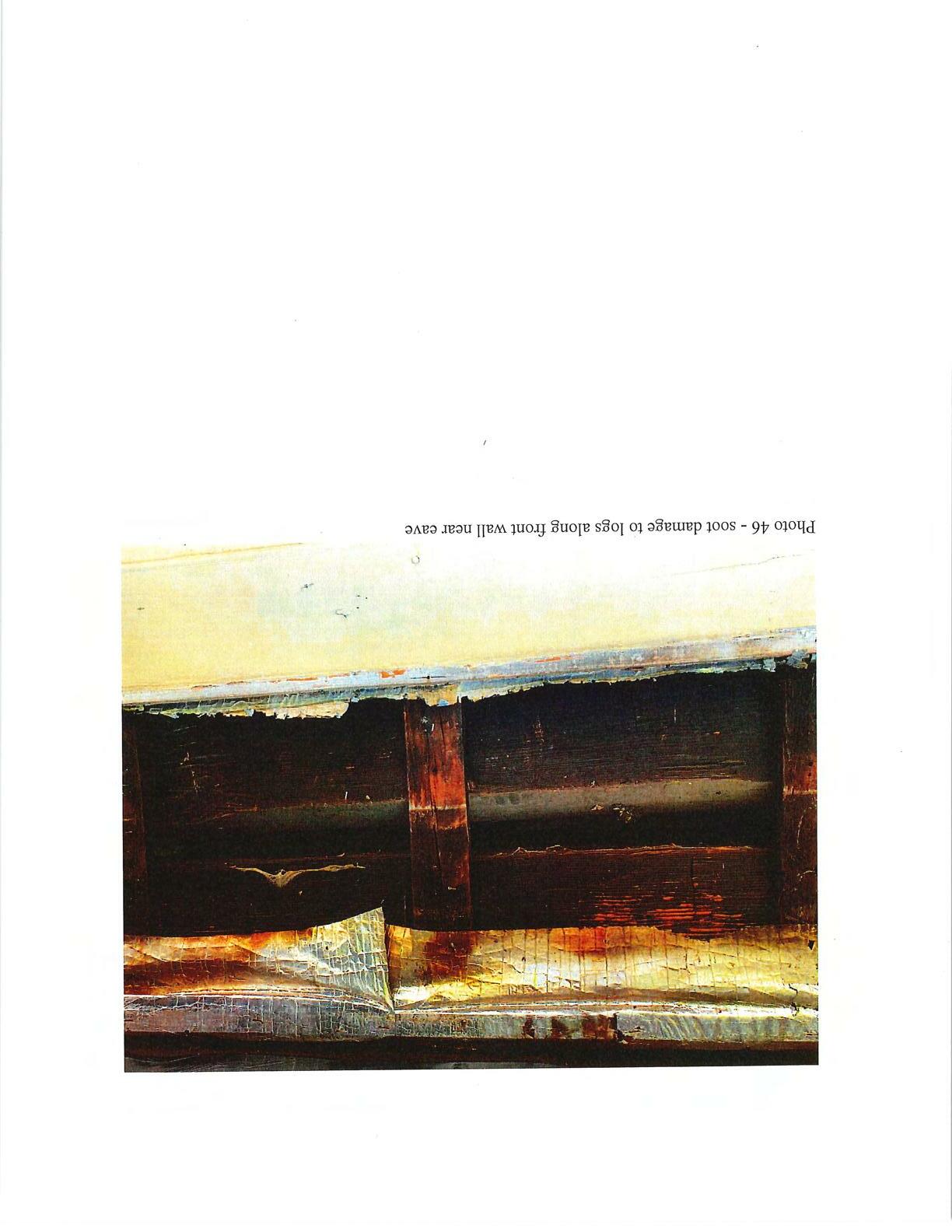
 Photo44 - soot damageto exterior logs aboveporchroof

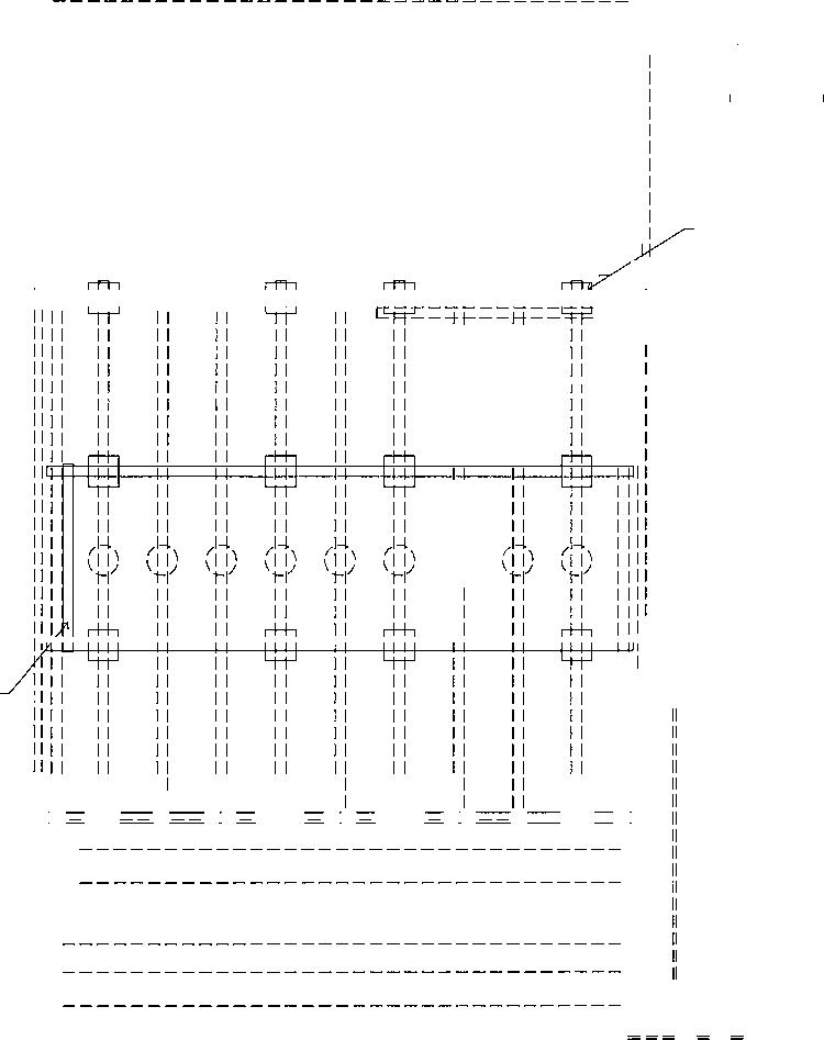
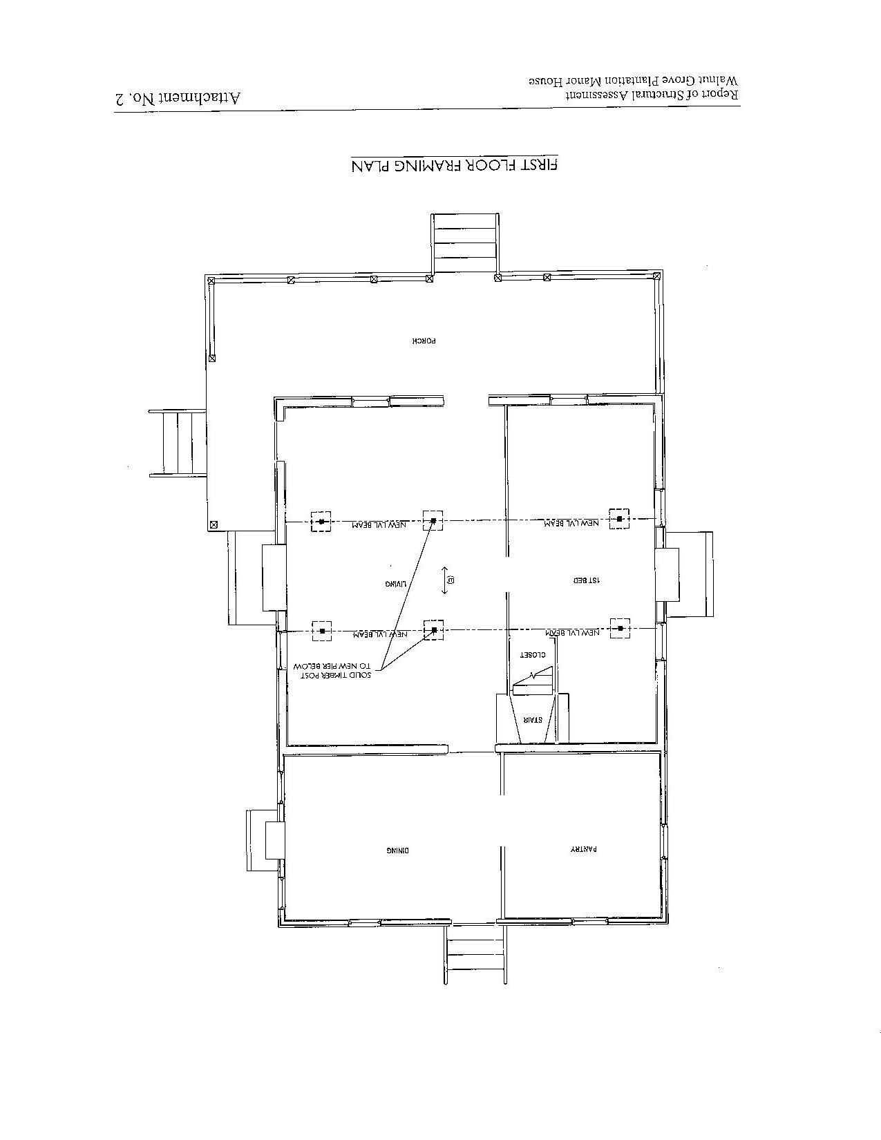
ATTACHMENT2 - SchematicFirstFloorFramingPlan


May18,2020
McMillanPazdanSmith POBox5331 Spartanburg,SouthCarolina29304
Attention: Reference: DearDonnie:
Mr.DonnieLove,AIA
Limited Visual Observations

Walnut Grove Plantation Roebuck,SouthCarolina S&MEProjectNo.3326-20-048
S&ME,Inc.(S&ME)ispleasedtohavetheopportunitytosubmitthisreportofourvisualobservationsforthe abovereferencedproject.OurworkwasconductedinaccordancewithourProposalNo.33-2000147datedMay 11,2020.
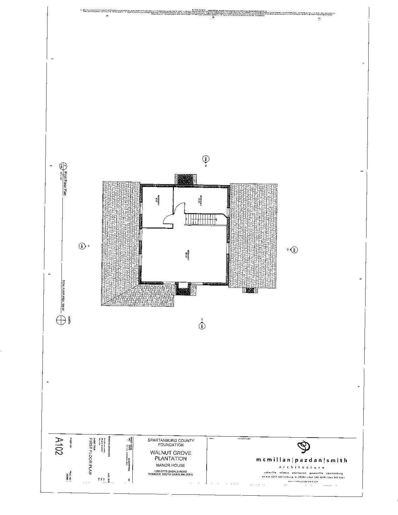
Weunderstandthatvisual·observationoftheconditionoftheexistingwoodmembersandmasonrycolumns beneaththefirstflooroftheManorHouseattheWalnutGrovePlantation(asdepictedintheExistingFloorPlans datedApril24,2020providedbyMcMillanPazdanSmithArchitecture)neededtobedocumented.OnMay4and 8,2020ourrepresentativesvisitedthesitetoconductvisualobservationsofthecurrentconditionofthesupport membersofthestructure. Forreportingpurposes,thebuildingwasseparatedintothreeareas:PorchArea,TwoStoryArea,andSingle-StoryArea.Ourvisualobservationsalongwithsketchesandphotographsareattached.
Weappreciatetheopportunitytobeofservicetoyouonthisproject. Donothesitatetocontactusifyouhave anyquestionsorconcerns.
Sincerely,
S&ME, Inc.

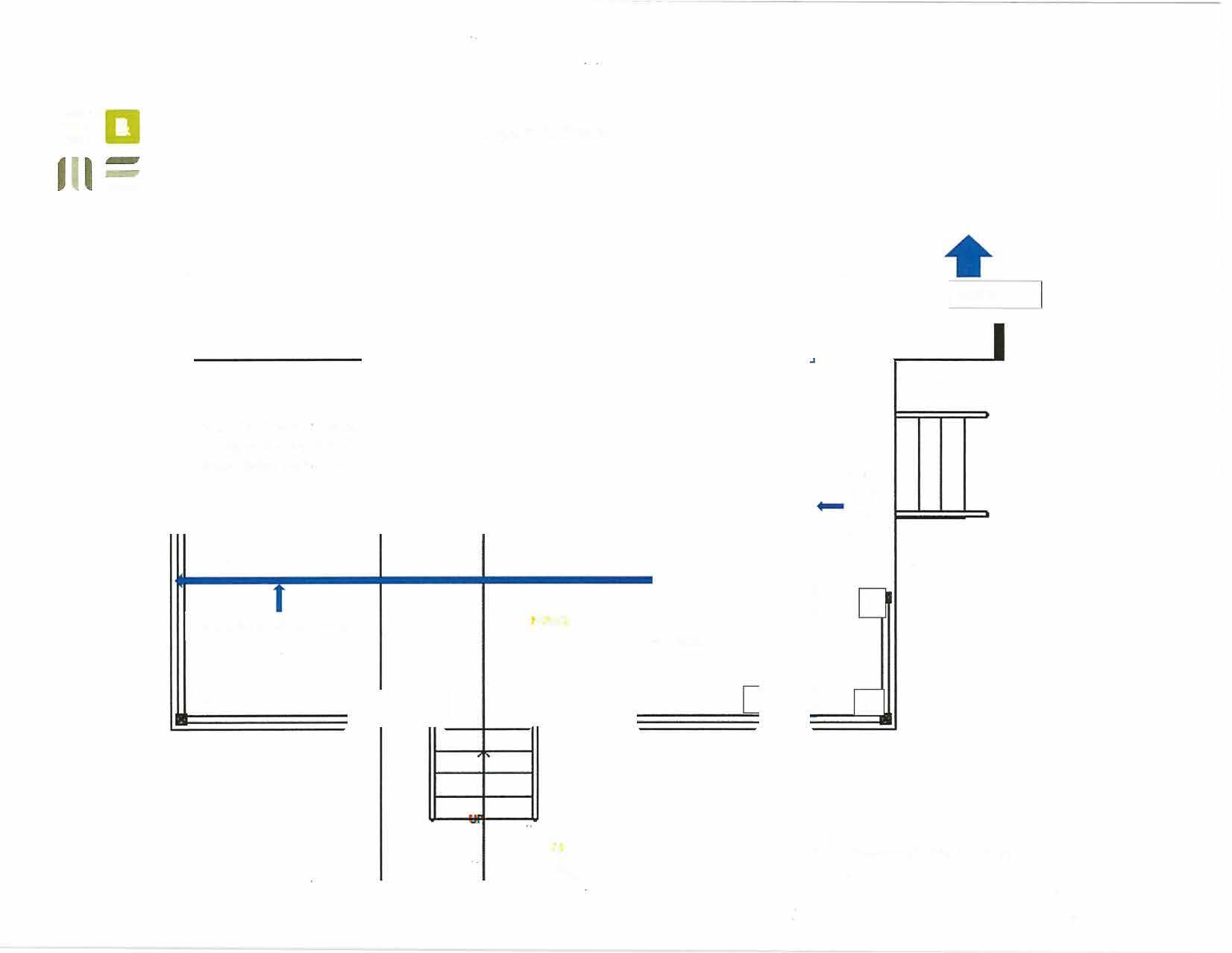
Single 2x10 band attached tooriginal 2-story llx12 heavy timber perimeter 2x10 joist at 1611 on center


2x1O's at16" on center 8
Limited Visual Observations

Walnut Grove Plantation Roebuck, South Carolina S&ME Project No. 3326-20-048
♦
Porch floor framing is not original. Floor framing in generally good condition (Photo 1 and 3).
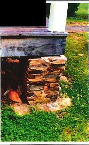
♦ Floor framing is not fastened to supporting piers (Photos 2 and 4).
♦ Porch posts are either supported directly by existing masonry piers (Photo 4) or on top of porch floor deck (Photo 2).
♦
Perimeter band at south, east & west walls of porch are double 2"x10".
+ Floorjoists are 2"x10" at approximately 16 inche� on-center.
♦ A single 2"x10" is attached to the original 11"x12" rough cut heavy timber (HT) at the north perimeter of the porch.
• No ledger strip orjoist hangers were observed.
♦ Pier #9 is newer brick supported on a new concrete pad that extends to the chimney on the east side of the structure.
♦ Concrete pads have also been added under piers 1, 10, and 11 (Photo 5).
Note: The added concrete pads observed could not be adequately accessed to help determine the extent of support and/or size.


Limited Visual Observations Walnut Grove Plantation Roebuck, South Carolina
♦
north
Perimeterbandsappeartobeoriginalheavytimber (HT).The�andsouthtimbersarerough-cutat 11"x12"(approx.).The�ands�timbersarerough-cutat4"x10"(approx.)
♦ Theeastandwestperin�\�t5 erHT ���tbeensupplementedwitha 2"x10""sistered"tothetimber.
♦ ThesouthperimeterHTbandhasbeensupplementedwithanapproximate4"x6"ledger. (Photo#1)
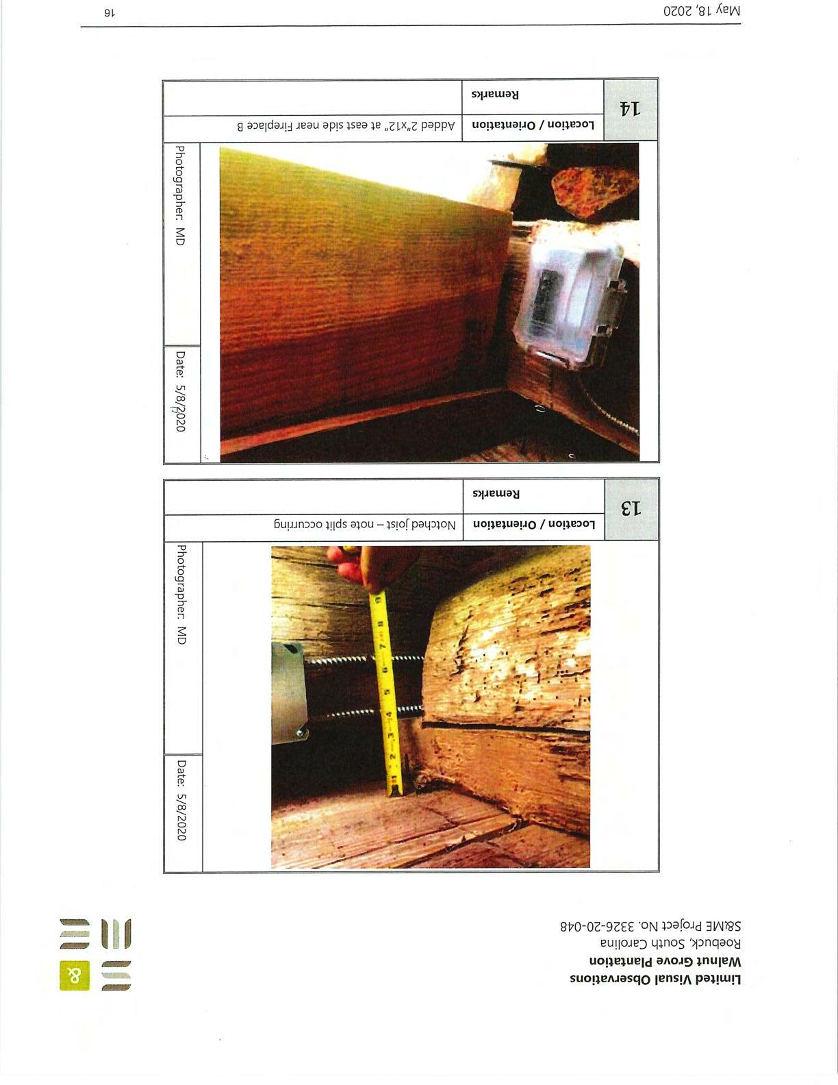
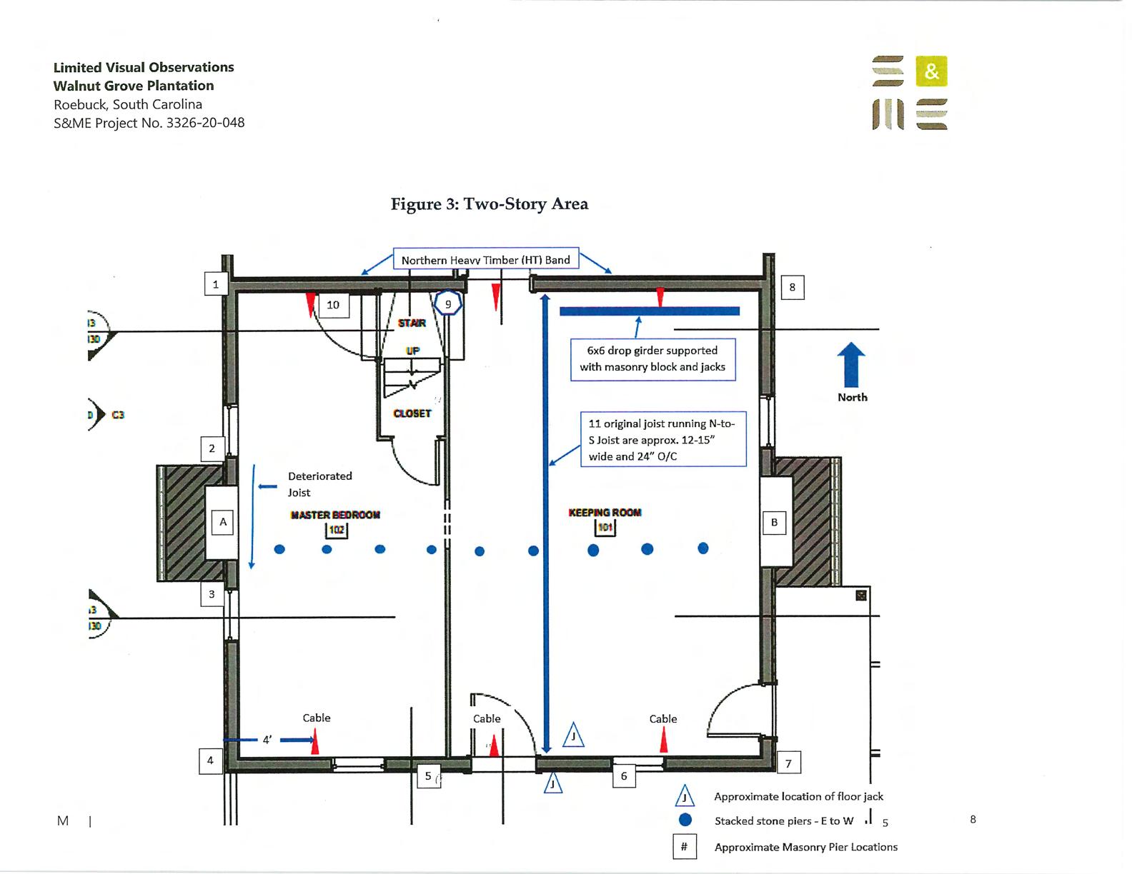
♦ Eleven (11)floorjoistrunnorth-to-southandarenotchedapproximately25%-70%bearingontheHT perimeterband.Splittingoffloorjoistswasobservedinnumerousareasattheledger. (Photo#1and #13)
♦
ThenorthperimeterHTbandisamixture.TheEast40%ofthebuildingwidthis12"x12"heavytimber. Theremainderappearstobe original4"x10"heavytimberswiththreelayersof2"x12"conventional materialaddedatlaterdate.
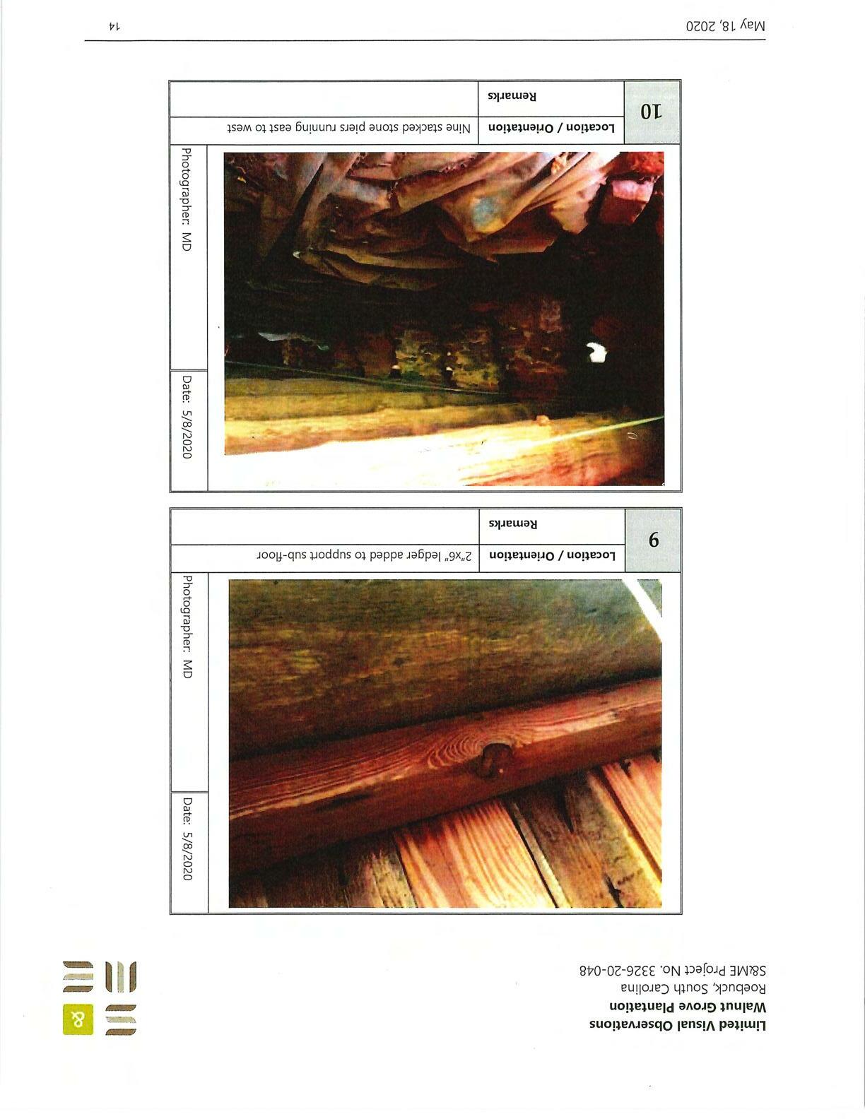
♦ A2"x6"ledgerhasbeenaddedtothe westsidefromPier1to FireplaceAtosupportthesub-floor. (Photo#9)
♦ Nineoriginalstackedstonepiersareplacedeast-to-westintermediateforfloorsinthe N-S dimension. (Photo#10)
• Threetensioncables (west, middle, andeast)havebeenaddedrunninginthenorth-southdirection. TheEastandWestcableshavetension.Themiddlecableisnotundertension (cablelayingonthe ground). (Photo#2and#8)
♦ Thejoistidentifiedinsketchnear Fireplace"A"issubstantiallydeteriorated.Thereisevidenceofwater damagedanddry-rot. (Photo#7)
♦ Telescopingsupportbraces /\ havebeenaddedtotheSouthWallHTperimeterbandinthe locationsshownin Figure3.�
♦
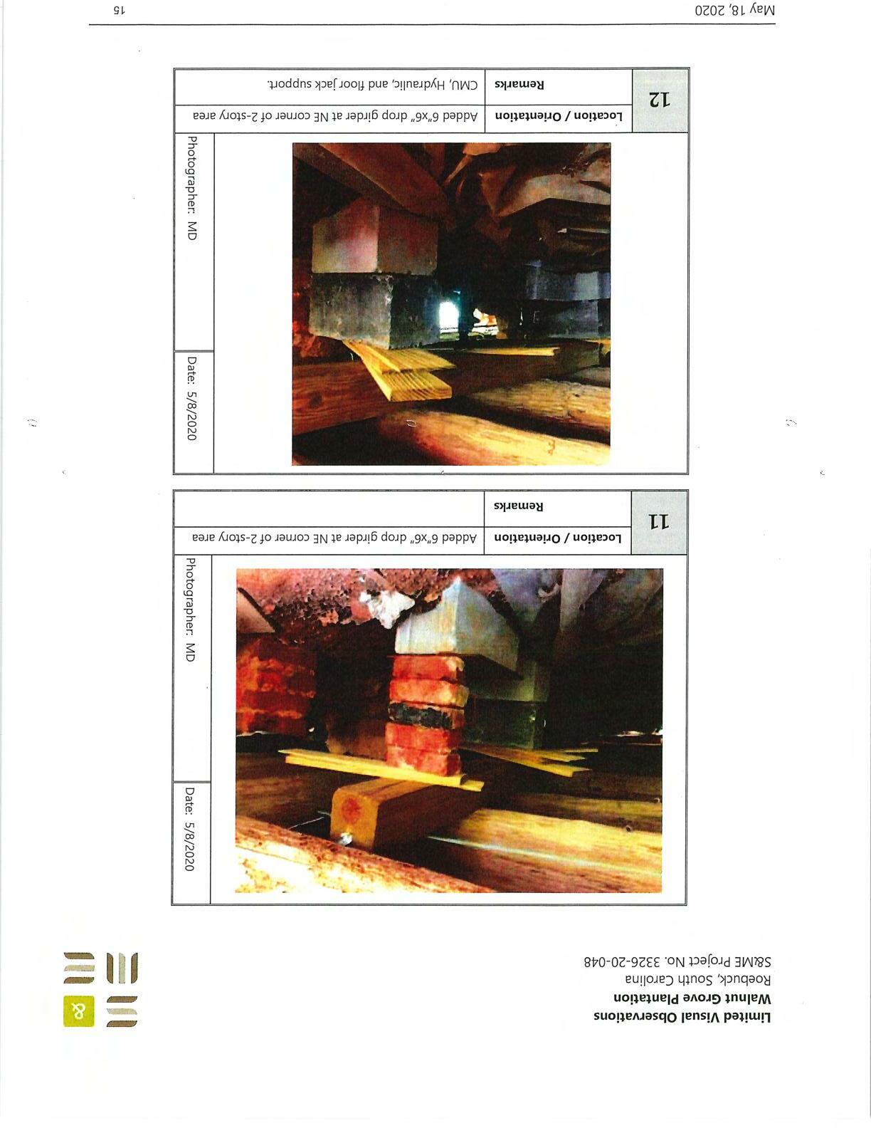
Inthenortheastareaa6"x6" dropgirderhasbeenaddedtosupportthefloorabove. Thedropgirder issupportedwithfloorjacksandCMU & Brickpiers withwoodshims. (Photo#11and#12)
♦ A2x12hasbeen"sistered"totheexteriorbandfromthePier#8to Fireplace B. (Photo#14)
♦ An8"x8"treatedtimberposthasbeenaddedforsupportunderthe NorthHTperimeterbandatthe Master Bedroom/Keeping Roomcommonwall.(Seesupport#9in Figure3forapproximatelocation)

♦ Concretehasbeenpouredatthefireplaceareas. Theconcreteextendsapproximately12"fromthe brickface; however, wewerenotabletodetermineiftheconcreteisprovidingsupportunderthe fireplaces. (Photo#4)
♦
Concretepadshavebeenpouredundertheexistingpiersidentifiedby0 shownin Figure3. (Photos#3,#5,and#6)
Walnut Grove Plantation
Roebuck, South Carolina
S&ME Project No. 3326-20-048
Location/ Orientation Remarks
Floorjoist notched +50%. Partial rest on original heavy timber and added 4"x6" ledger.
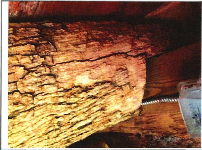
split occurring.

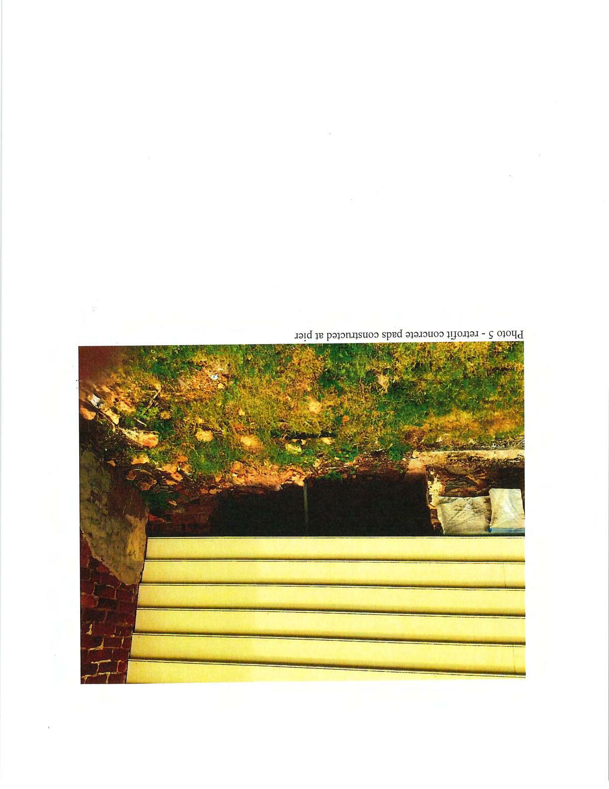

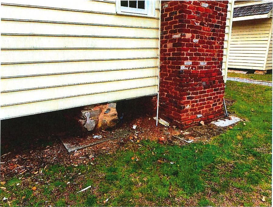 Photo 6 - retrofitconcretepadsconstructed atpier andchimney



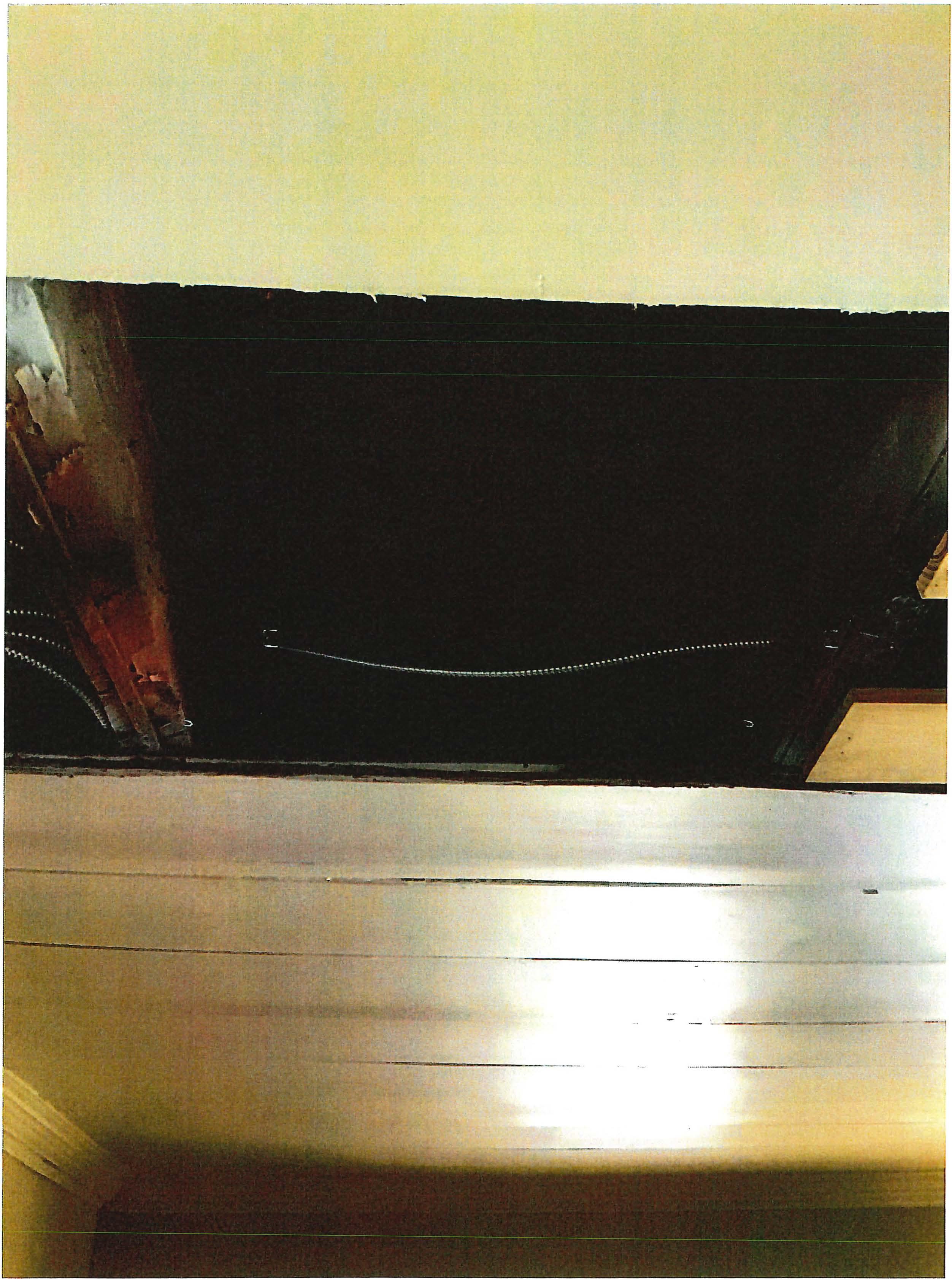 Photo 8 - firstfloorjoists

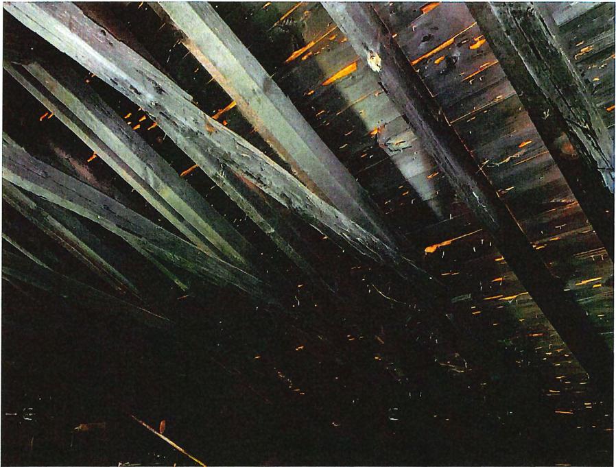 Photo 9 - existing attic androofframing attwo-storyprimary structure
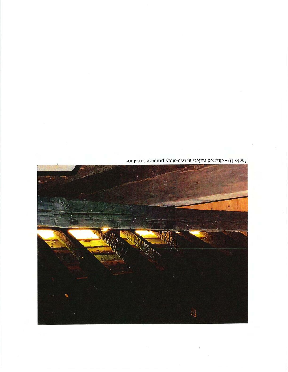
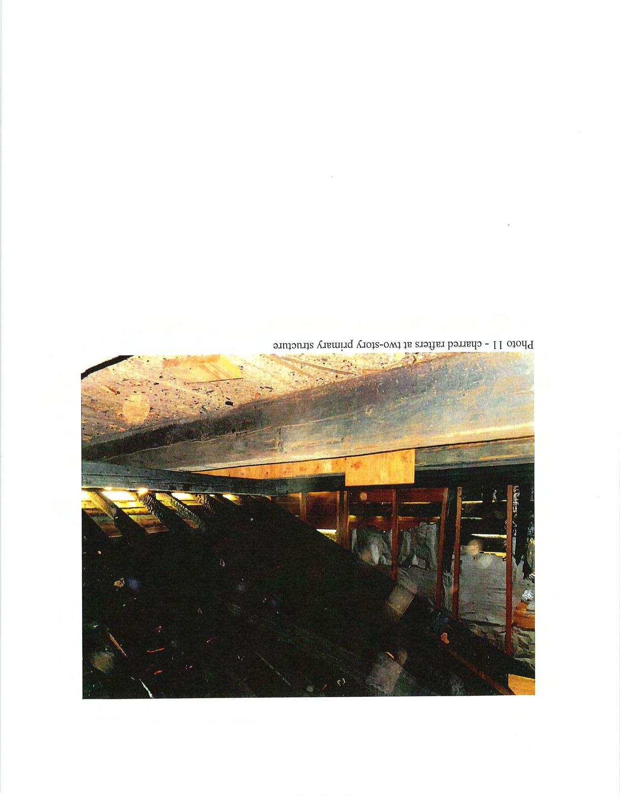

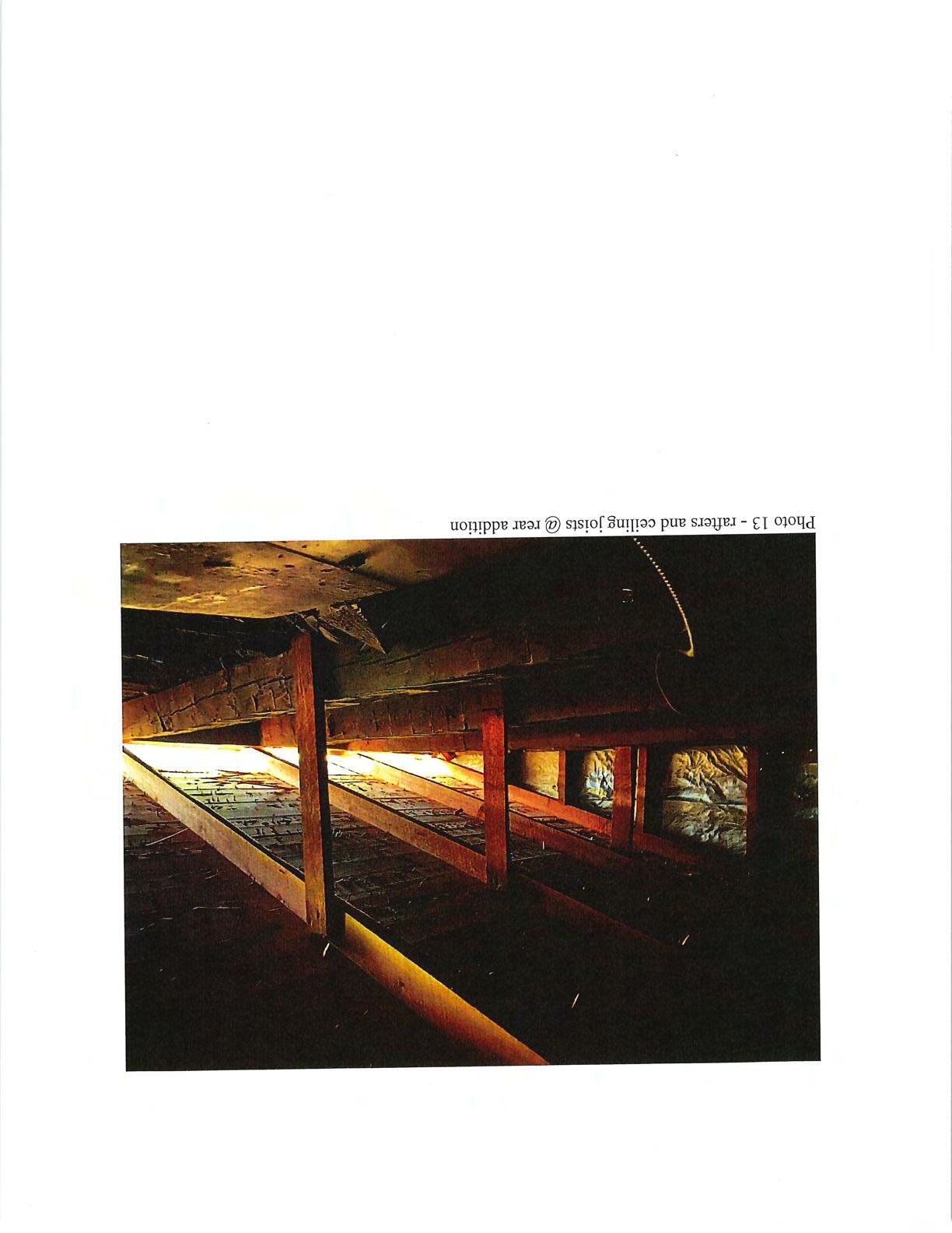

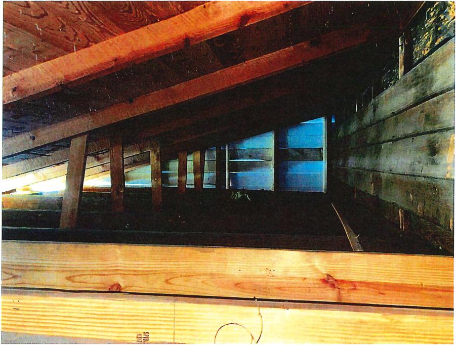 Photo 14 - rafters and ceilingjoists @ rearaddition
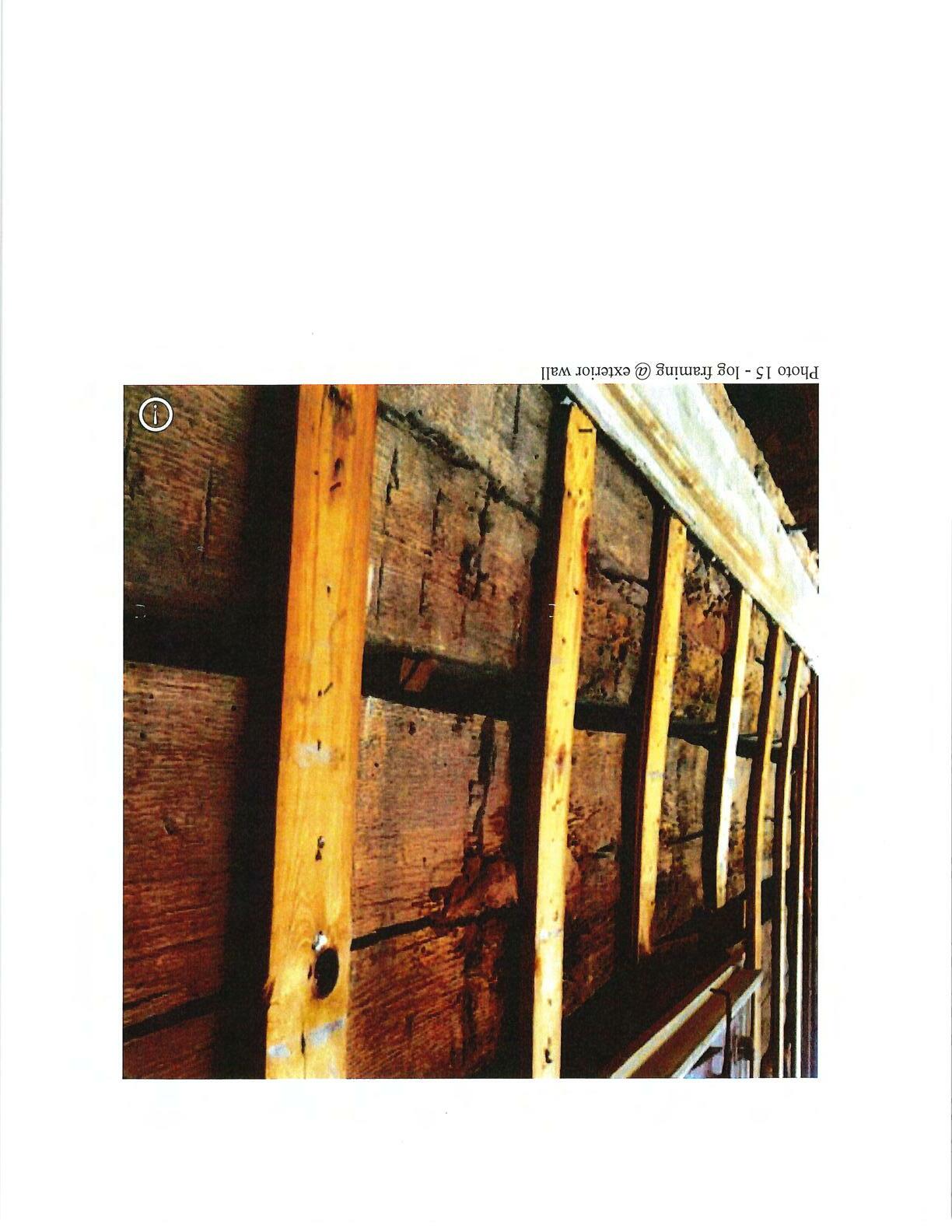

 Photo 16 -notcheddovetail connections atcorners


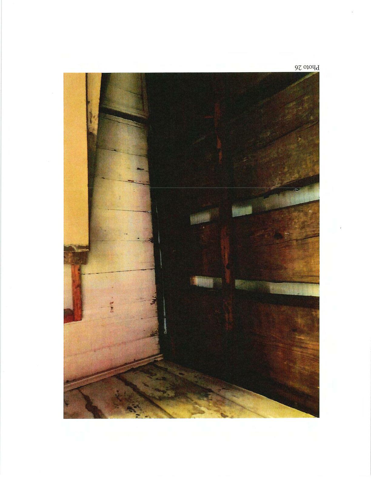
k_,7;-�-'.}Photo27 - decomposed log atrightrearcomer above low roof
