TRILLIUM


PROJECT DESIGN AND FABRICATION:
University of Tennessee College of Architecture and Design Fall 2022 Studio: ARCH 496
Professor James Rose AIA, Director of Institute for Smart Structures
Students: Maxwell Batchelor, Matthew Baumgartner, Abram Harris, YuHsuan Lee, Cayden Masters, Mary Catherine McGovern, Perto Michel, Molly Miller, Jackson Motley, Rachel Paganelli, Audrey Seyfried, Blake Spencer, Gabe Wall, Nicholas Williams
3D PRINTING + FABRICATION:
Loci Robotics Max Heres Ph.D & Jeff Foote PE

SPONSORS:
University of Tennessee Research Park at Cherokee Farm
Tom Rogers, President and CEO Rickey McCallum, Vice President of Business Development Angelee Day, Chief Operating Officer
University of Tennessee Office of Research, Innovation and Economic Development (ORIED)


Marc Gibson, Associate Vice Chancellor Darcy Rathjen, Director of Research Operations Site Activation
American Institute of Architects,East Tennessee Chapter
Josh Shaffer AIA, President Jen McMahon, Executive Director

PROJECT NARRATIVE
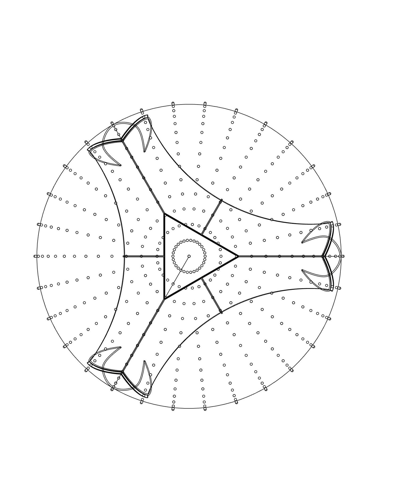
Inspired by the graceful symmetry of the Trillium flower, this pavilion expresses a rare and beautiful biological geometry. The Tennessee Trillium is a rare species of flower only found in East Tennessee. The flower blooms a ternion of petals offset by three subsequent sepals. The curvature of the petals allow them to support one another and expand outward. The petals originate around a central origin. Each one rotates approximately 120 degrees creating a perfectly symmetrical tripod. The trillium pavilion explores this geometry as it is applied to a dome form to generate shade and seating for pedestrians.

TENNESSEE TRILLIUM


GEOMETRY STUDY


PARTS


The structure for the Trillium Pavilion was designed to be 3D printed and modular for easy assembly and disassembly. The specific site chosen for the structure adds an extra bottom piece to better flow with the topography.


The Trillium Pavilion includes multiple different parts that all fit togther seamlessly. There are 82 total pieces in this construction. The pieces include: 3 Bases, 6 Shells, 1 Crown, and 75 nuts and bolts. All holes will be drilled during intial construction and shall be reusable for further assembly and disassembly. Each piece will be fastened together with nuts and bolts. Then silicone caulking will be applied to smooth the gaps.
The overall structure includes 82 pieces that weigh around 1200 pounds. The majority of the structure is 3D printed with carbon fiber reinforced acrylonitrile butadiene styrene, while the seats will be made from synthetic wood polymer.

x3
The three bases will be printed individual on the print beds at LOCI Robotics along with printed shims. Although the structure has a level base, it can be placed in different topographies with different shims. Each shim is custom printed to match the exact terrain of the installation site. Those shims will be printed as seperate parts to ensure that each seat and the crown will remain a level surface upon completion.


Along with being level, the bases are capable of relocation while only needing new levels underneath. Each base is designed to be lightweight enough for 2 people to transport with ease, while also being durable to withstand the loads of the shell above.

The shims are to be anchored into the ground and then bolted onto the bases.
WEIGHT PER: 127.87 lbs VOLUME PER: 1.85 ft³


TRILLIUM | UNIVERSITY OF TENNESSEE, KNOXVILLE DRAWN BY:
TRILLIUM | UNIVERSITY OF TENNESSEE, KNOXVILLE DRAWN BY: ABRAM HARRIS + MATTHEW BAUMGARTNER + NICK WILLIAMS
The shell structure is designed to be a self-supporting surface with double curvature. The complex form of the shell requires the components to be printed together on the print bed. The print bed layout allows for the print pieces to be more stable as each layer is added. The printing process for the shell pieces involves milled out foam blocks that help support the structure during printing process. There is a chance of warping during printing, so the bottom flanges will need to be drilled down onto the print base.


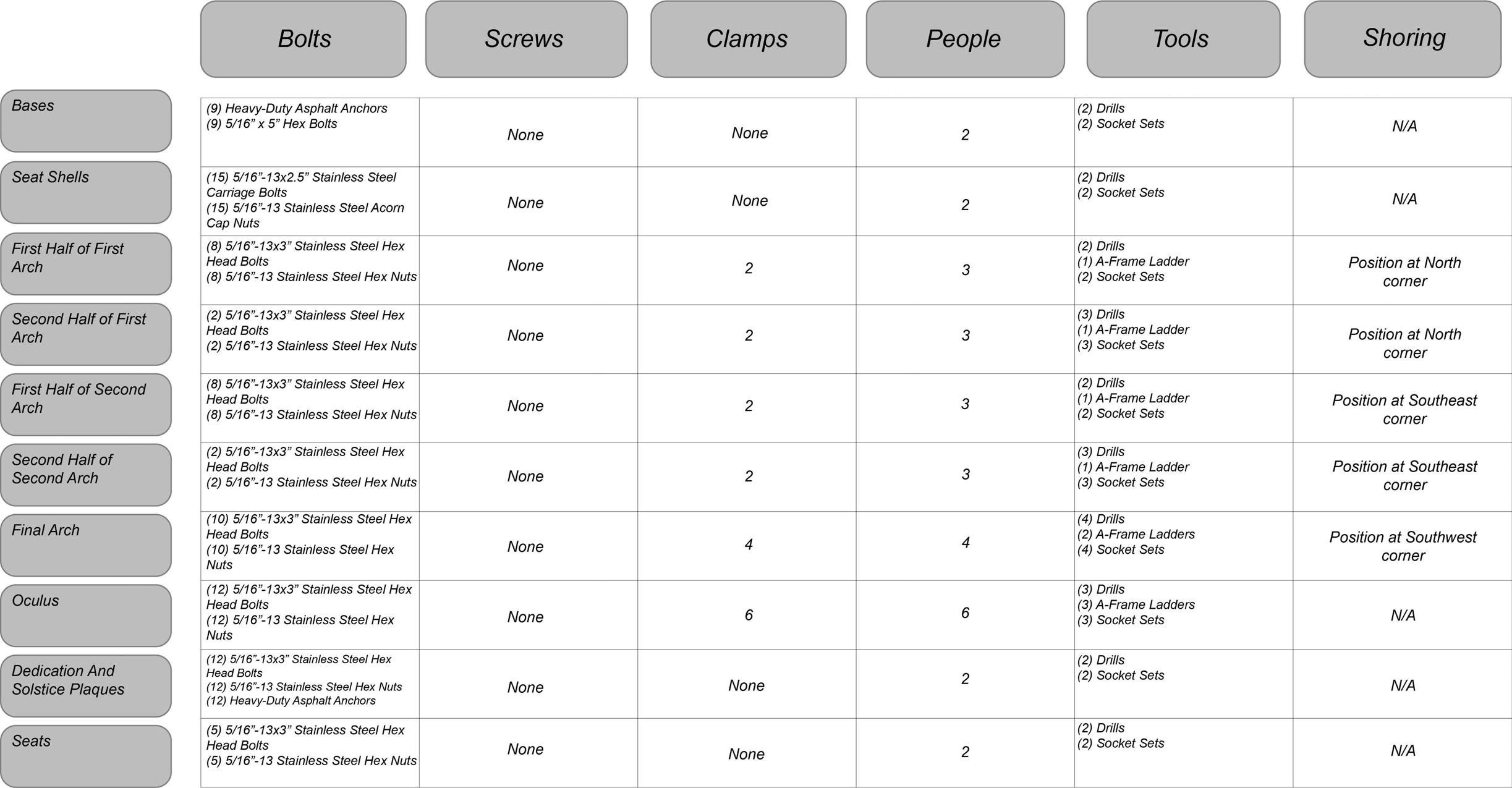
Once the shells are separated from their supports, they will be bolted to the bases in an arch formation. There are a total of 51 nuts and bolts needed for assembly. Each hole will be aligned and predrilled onsite to ensure perfect alignment. When shell pieces are assembled together, they will have the structural capacity to support the aperture crown location above in the middle of the pavilion.
1’2’4’
MATERIAL: Black Carbon Fiber Reinforced ABS
WEIGHT PER: 136.17 lbs.
VOLUME PER: 1.97 ft3
TRILLIUM | UNIVERSITY OF TENNESSEE, KNOXVILLE DRAWN BY:
OF TENNESSEE, KNOXVILLE

The crown piece of the structure is the final component in assembly. The design features a parametric component that caps off the pavilion and provides shading throughout the day. The crown houses integrated lighting within.
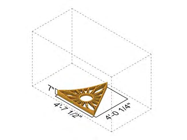
The crown oculus is assembled with 18 nuts and bolts, along with washers to fit between the spaces of the shell and crown. The tolerance between these two surfaces is an 1/8” which can be filled with washers to fasten the crown into place. The holes for the bolts are predrilled. The spacing of the bolts varies in the crown because the tools cannot fit into some of the gaps in the crown design.

The piece is roughly around 62 pounds and will need shoring to help with assembly and fitment. [The material of the crown is different than the rest of the structure.] The crown will be printed with a glass fiber reinforced ABS instead of carbon fiber.

1’2’4’
MATERIAL: Gray Glass Fiber Reinforced ABS

TOTAL WEIGHT: 62.90 lbs
TOTAL VOLUME: .91 ft3
TRILLIUM | UNIVERSITY OF TENNESSEE, KNOXVILLE DRAWN BY:
OF TENNESSEE, KNOXVILLE

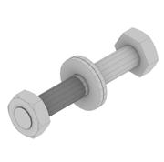
Each component of the structure incorporates their own flange connections that are printed to match perfectly with the curves of the shell. Each flange is connected with a series of 5/16 inch hex bolts. Each bolt on the outer face of the pavillion is stainless steel, while the interior bolts are zinc plated steel.


At he time of design, the pavillion will be located at the head of the greenway near the parking lot of the JIAM Facility. However, this pavillion is also designed for the possibility of relocation in the future.

The pavillion will be located on uneven asphalt. To accomodate for this ground condition, two 3D printed bases are designed to act as shims. They ensure that the pavillion can be constructed on uneven ground.
Two methods were used to evaluate the slope of the ground. A laser transit surveying tool and a LiDAR scanner were used to evaluate the surface for most accurate results. One leg of the pavillion was designed to be set directly on the ground surface. Bases were designed to accomodate the ground changes beneath the other two legs.

0’ 5’ 10’ 15’
Locating
base pieces on
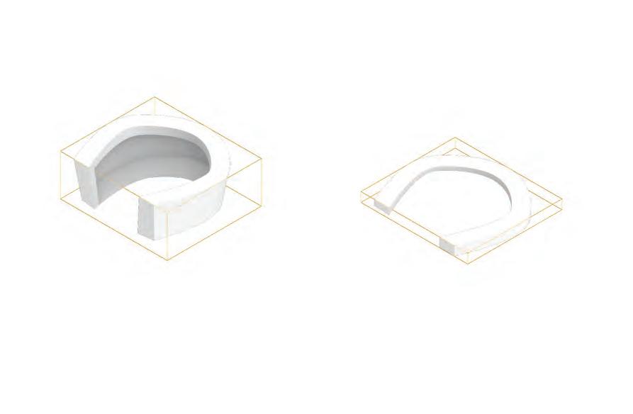
Leg B. This leg’s base is 2.76 inches tall. One connection can be used to connect the pavillion and base to the ground anchors. Similar to the first leg, this will be done through drilling through the two pieces and using nuts and bolts.
Leg C. The final leg’s base is 10.92 inches tall. This is too tall to use a single connection. Therefore this base piece is designed with a lip at the top and bottom. The base will be attached to the ground anchors with nuts and bolts. This connection will also require a hillside washer as the bottom lip has to be angled for the purposes of 3D priting. Then the leg of the pavillion can be attached to the base with a separate connection also of nuts and bolts.


DRAWN BY: PERTO MICHEL and AUDREY SEYFRIED

SCAFFOLDING: DESIGN + MATERIALS
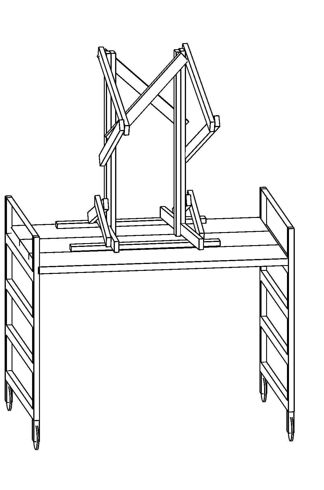
The angled “arms” make contact with the interior side of the structure allowing it to be held in position while securing. Due to the curved form of the structure, the shoring makes two points of contact on the structure reducing scratch marks or indentions. While the base of the shoring sits on the scaffolding walk planks, temporary shoring is required as the site has a gradual slope. The structure is assembled in a series of arches. The shoring is intended to sit on either side of the flanges allowing the pieces to


SCAFFOLDING SECTION
be bolted together. Once the first arch is secured, the scaffolding structure rotates 120 degrees to support the second arch. Temporary supports will be required to support the first arch while the scaffolding structure has been moved. The rotation requires adjustments to the temporary shoring in order to address the sloping of the site. This process continues until the final arch has been erected and secured into place. The width of the scaffolding allows it to rotate beneath the structure without interfering with any elements. Once the primary structure is secure, the wood shoring will be removed to insert the oculus. This piece is lifted onto the metal scaffolding and secured into place from the interior. This scaffolding design employs inexpensive materials and allows for an efficient assembly process.
POINTS OF CONTACT
72 DEGREE ANGLE
5’-9”
SCAFFOLDING DIAGRAM
DRAWN BY: RACHEL PAGANELLI
DRAWN BY: RACHEL PAGANELLI
SHORING
SCAFFOLDING: ON SITE SHORING
SITE GRADE REQUIRES TEMPORARY SHORING BENEATH WOOD
SCAFFOLDING ROTATES
WITHIN STRUCTURE DURING EACH ASSEMBLY PHASE 120 120
VARIABLE BLOCKING TO LEVEL DOME SHORING

TRILLIUM | UNIVERSITY OF TENNESSEE, KNOXVILLE
TRILLIUM | UNIVERSITY OF TENNESSEE, KNOXVILLE
DRAWN BY: RACHEL PAGANELLI
DRAWN BY: RACHEL PAGANELLI
site information - page 8
1 SITE 2 3 4 5
paper template - page 9 shim installation - page
DRAWN BY: MAXWELL BATCHELOR
TRILLIUM
arch 2 installation - page 6
arch 2 completion - page 6
6 7 8 9 10 11
arch 3 installation - page 6
arch 3 completion - page 6
aperture and seat installation - pages 7, 16 completion
UNIVERSITY OF TENNESSEE, KNOXVILLE 15 TRILLIUM | UNIVERSITY OF TENNESSEE, KNOXVILLE
DRAWN BY: MAXWELL BATCHELOR
DRAWN BY: MAXWELL BATCHELOR
DRAWN
SEAT A

SEAT B


SEAT C
The seats, located 18 inches off the ground, are made of recycled wood fiber reinforced PLA and attached using a series of carriage bolts, nuts and washers. Arranged with two on the sides and one at the top of the seat, each bolts is 5/16”-18 x 2.5” stainless steel carriage bolt, one 5/16” stainless steel washer on the 5/16” acorn cap nut. These bolt dimensions are the same used across the structure of the pavilion.
A. Pick Point L-Brackets D.
OPTIONAL PIECES THICKNESS: 1/16” APERTURES: 3/16”
Project Team: University of Tennessee College of Architecture and Design Institute for Smart Structures
James Rose AIA, Director
Students: Maxwell Batchelor, Matthew Baumgartner, Abram Harris, YuHsuan Lee, Cayden Masters, Mary Catherine McGovern, Perto Michel, Molly Miller, Jackson Motley, Rachel Paganelli, Audrey Seyfried, Blake Spencer, Gabe Wall, Nicholas Williams
Loci Robotics
Max Heres Ph.D & Jeff Foote PE
University of Tennessee Research Park at Cherokee Farm
Tom Rogers, President and CEO, Rickey McCallum Vice President of Business Development Angelee Day, Chief Operating Officer
University of Tennessee Office of Research, Innovation and Economic Development
Marc Gibson, Associate Vice Chancellor Darcy Rathjen, Director of Research Operations Site Activation
American Institute of Architects, East Tennessee Chapter Josh Shaffer AIA, President
Jen McMahon, Executive Director
The geometry of the native flower Trillium tennesseense generates this pavilion’s form and structure.These triangular guidelines - recurring in nature and graphic standards - are perfectly suitable for the division of a 3D printed structure. Each structural division creates a 120 degree angle in both the natural Trillium and the 3D printed structure, with a complimentary angle at 60 degrees. The printing process allows for a thin, doubly curved surface which provides both structure and strength.
X3
STAINLESS STEEL PLAQUE + MOUNT.
EACH PLAQUE TO BE MOUNTED AT APPROX. 5’5” AT CENTER JOINT OF EACH INNER LEG OF SHELL.
STAINLESS STEEL MOUNT JOINERY DETAIL STAINLESS STEEL PLAQUE + MOUNT JOINERY DETAIL
DRAWN BY: M. MILLER
DRAWN BY: MOLLY MILLER
