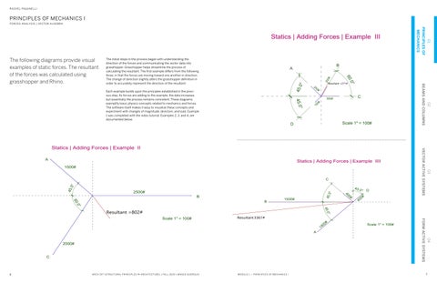
Statics | Adding Forces | Example III
The following diagrams provide visual examples of static forces. The resultant of the forces was calculated using grasshopper and Rhino.
2500#
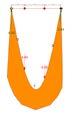
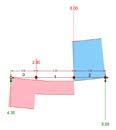
The initial steps in the process began with understanding the direction of the forces and communicating the vector data into grasshopper. Grasshopper helps streamline the process of calculating the resultant. The first example differs from the following three, in that the forces are moving toward one another in direction. The change of direction slightly alters the grasshopper definition in order to accurately represent the direction of the resultant.
Resultant =802#
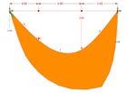
Each example builds upon the principles established in the previ ous step. As forces are adding to the example, the data increases, but essentially the process remains consistent. These diagrams exemplify basic physics concepts related to mechanics and forces. The software itself makes it easy to visualize these concepts and experiment with changes of magnitude, direction, and load. Example 1 was completed with the video tutorial. Examples 2, 3, and 4, are documented below.
45.0° 45.0°
250# 200# 150#
B 60.0°
B C
Resultant =271#
300#
A Scale 1" = 100# D Scale 1" = 100#
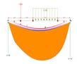
LOAD: 1.0 LOAD: 8.0 DEFORMATION: 30
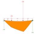
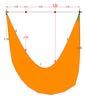
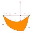
These diagrams exemplify various scenarios applied to beams. Each group represents a change in load or material. This experimentation with data provides virtual evidence of real life conditions.
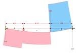
Prior to calculating forces through computational software, we first practiced the method by hand. It is imperative to understand the relationship between different forces and supports. This rudamen tary process is a necessary step in understanding how Rhino and Grasshopper help streamline the calculations. While the conept is simple, doing these calculations by hand will quickly become extremely complex when more variables are added.
Therefore, it is necessary to utilize Rhino, Grashopper, and Karamba to make senese of the data and create visual representations of the result. These diagrams exemplify different force analysis with changed variables. It is clear how the results change based on the load and material. This is simply scratching the surface of the multi tude of real life problems that exist in architecture and engineering.
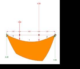
MANUAL CALCULATION:

Taking the moments about R2 SumMr2=0 (-6000# x 5’) - (3000# x 11’) + R1 x 15 = 0 -30,000# - 33,000# + R1 x 15 = 0 - 63,000 = - R1 x 15
R1 = 4,200#
R1 + R2 + - 3000# - 6000# = 0 4200# + R2 - 3000# - 6000# =0

R2 = 4,800#
STEEL
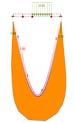
MOMENT DIAGRAM
SHEAR DIAGRAM


LOAD: 4.4 LOAD: 4 DEFORMATION: 45
STEEL
LOAD: 2.3 LOAD: 8.0 DEFORMATION: 16 STEEL CONCRETE
CONCRETE WOOD
LOAD: 1.0
LOAD: 0.9 DEFORMATION: 45.6

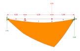
These diagrams exemplify various scenarios applied to beams. Each group represents a change in load or material. This experimentation with data provides virtual evidence of real life conditions.
Prior to calculating forces through computational software, we first practiced the method by hand. It is imperative to understand the relationship between different forces and supports. This rudamen tary process is a necessary step in understanding how Rhino and Grasshopper help streamline the calculations. While the conept is simple, doing these calculations by hand will quickly become extremely complex when more variables are added.
Therefore, it is necessary to utilize Rhino, Grashopper, and Karamba to make senese of the data and create visual representations of the result. These diagrams exemplify different force analysis with changed variables. It is clear how the results change based on the load and material. This is simply scratching the surface of the multi tude of real life problems that exist in architecture and engineering.
MANUAL CALCULATION:
Taking the moments about R2 SumMr2=0 (-6400# x 8’) - (1500# x 16’) + R1 x 20 = 0 -51,200# - 24,000# + R1 x 20 = 0 - 75,200 = - R1 x 20
R1 = 3,760 #
R1 + R2 + - 1500# - 6400# = 0 3760# + R2 - 1500# - 6400# =0

R2 = 4,140#
MOMENT DIAGRAM
SHEAR DIAGRAM


LOAD: 2.1 LOAD: .6 DEFORMATION: 21.02
STEEL
LOAD: 1.5 LOAD: 0.8 DEFORMATION: 13.5 STEEL
Planar Truss Analysis

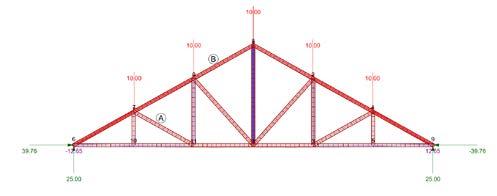


This assignment experiments with load and truss structure. We designed four different senarios in which consistent load amounts are applied to different truss structures. This analysis allows us to visualize the capabili ties of the structures and how they differ. The parametric capabilities of Rhino, Grasshopper, and Karamba make the data interactive. Different materials, load amounts, and force can create an infinite number of results. The results below indicate which structure is the most efficient. However, this strucutre is not particularly popular in day to day life. It is more common to see a strucutre like a parallel chord. This could be due to cost, materials, or construction methods.
In order to conduct these series of diagrams, the structures were drawn in Rhino. Then, the Rhino curves were made parametric using Grasshopper. After definig the curves that make the structure, the model is “cleaned” in karamba. Here, is where the forces and reactions can be adjusted to test different scenarios. Each structure was evaluated by locating the supports and the load locations. The four models have differernt data and numerically defined locations. With the correct inputs, the result is represented in the diagrams below.
HOWE
SPACE FRAME ANALYSIS
Internal stress forces
The following diagrams exemplify space frame structures with varying conditions applied. This analysis creates diagrams of internal stress forces. The main variable in the diagrams is the seed value. This value changes the random sequence of stress values applied on the structure. Each struc ture is labeled with the seed value.
The initial surface is created in Rhino. Grasshopper, then defines the surface as a mesh. Kangaroo is used to define the floor, anchor points, and distributed loads. The combination of this data is then utilized in Karamba to create a parametric analyis of the model. The loads, materials, and sup ports can all be adapted to produce different space fram structures. One key aspect of each diagram is recognizing the parts of each system that are under compression or tensile stress.