Control Strategies for the 4th Floor and Details of FBS Hub


Advanced Lighting Control Design | Msc Light and Lighting

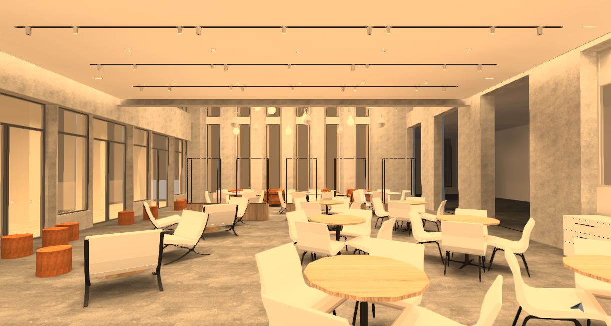
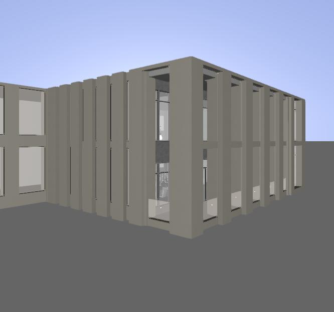
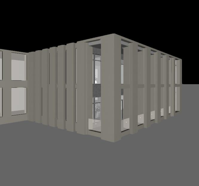
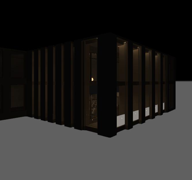
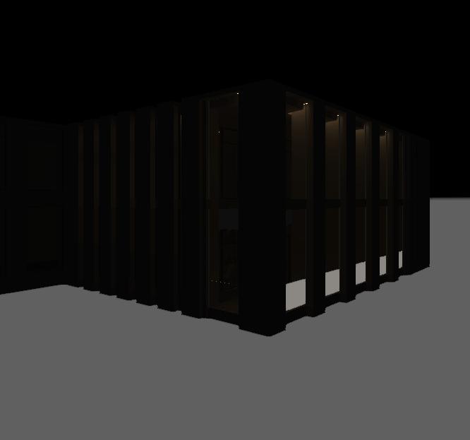
The London College of Fashion is part of the University of the Arts London. It is specialised in fashion education, research and consultancy. Moving to a new single campus on the Queen Elizabeth Olympic Park, UAL is part of a new development for London known as East Bank. East Bank will be a new powerhouse for innovation, creativity and learning. The new building is being designed by architects Allies and Morrison.

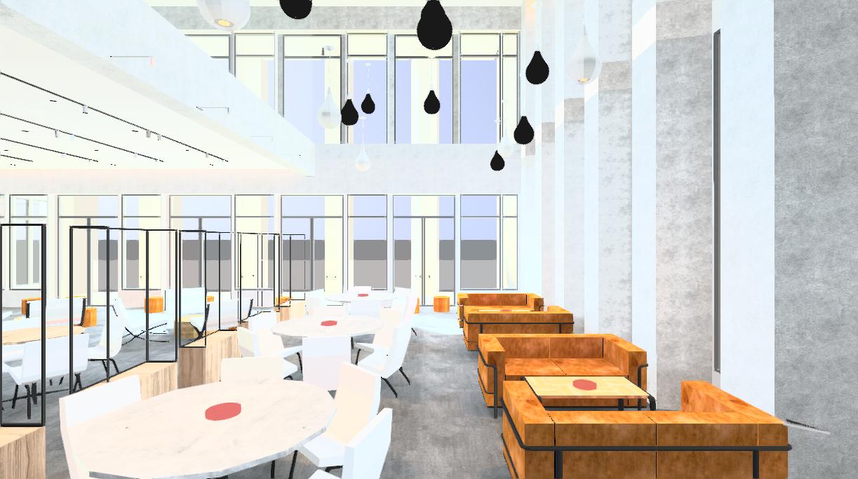
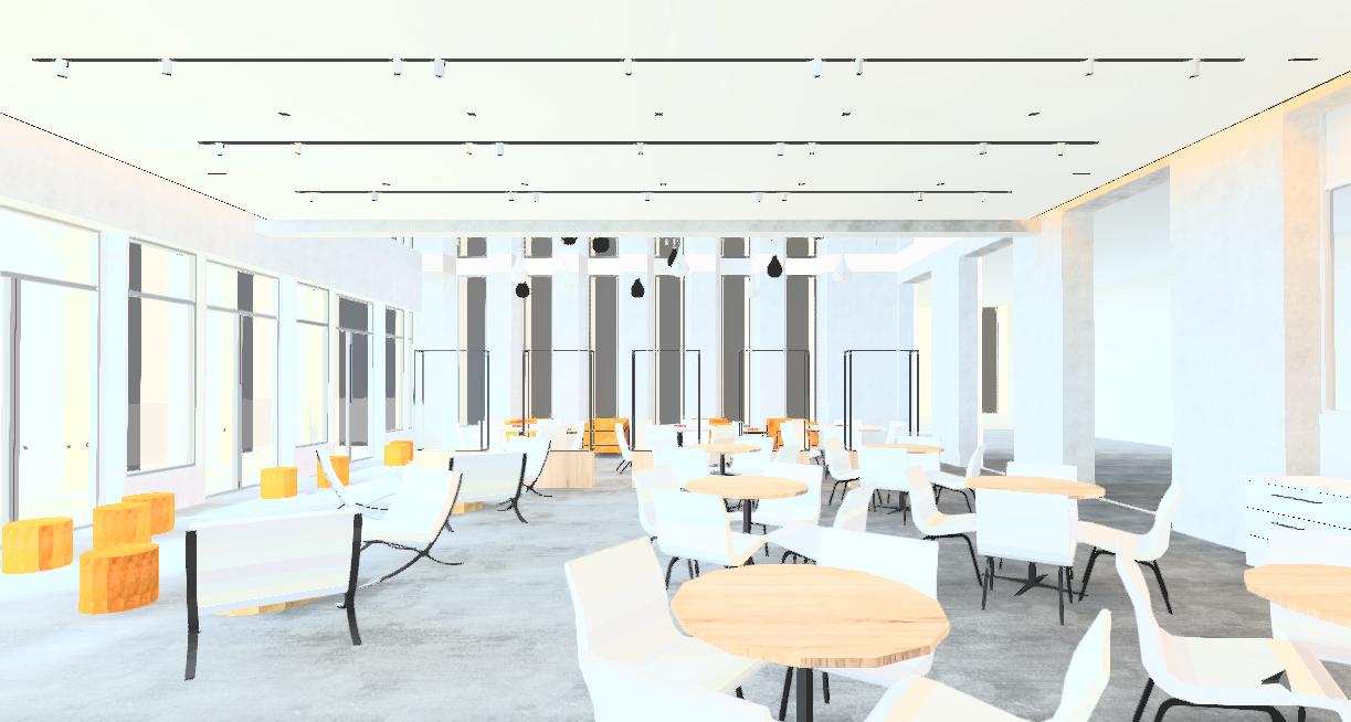
It will be day-lit and naturally ventilated, with factory-like steel-framed windows, internal atria for flexible learning, and lots of green spaces. As lighting designers, we took care of designing a tailor-made control strategy for the building, the customer and the users. Both well-adapted daylight harvest system and well-designed artificial lighting will work together to let this building standing out in East Bank area.
In this reports, lighting control design will be carring out for the 4th Floor of this building with detailed design of FBS Hub, from Stage 2 Concept to Stage 4 Technical Design a described in the RIBA Plan of Work 2020.


Our aim is to ensure visual comfort through the use of a control strategy designed for the building. The control strategy plays a fundamental role in obtaining a strong technical and stylistic content, always ensuring maximum visibility and making the space bright and appealing.
The intent of our project is the combination of functionality and sensoriality. We want to give lighting an added value, transforming it into a non-static tool: a device capable of interacting dynamically with the environment and the users.
Appropriate lighting control is an essential part of any lighting system and it plays a fundamental role in the reduction of energy consumption together with mindful use of renewable resources and attentive recycling practices.


User interfaces enable communication to and from devices. At the heart of our lighting control strategy there is the search for a lighting system tailored to the needs of space users.
The lighting control system of the building is designed based on the clients energy reduction objective and on the cost of installation and maintenance. Flexibility is the key word to support the user’s visual needs and create a desired mood or ambience.
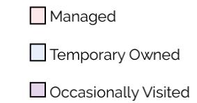
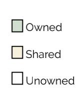
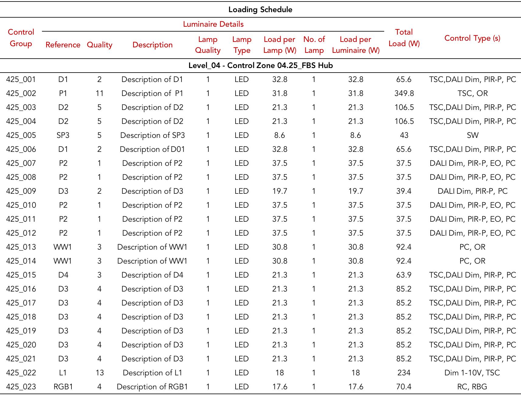
Control Design of the 4th Floor and Details of FBS HubLighting control strategies, such as real occupancy control, daylight linking strategy, time switch, tuning and dimming, can be combined to save energy in specific areas of a building. The goal for this project the lighting control system for the forth floor of LCF building is to reduce energy consumption while providing adequate light for the tasks. The lighting control strategy are built minding the different lighting needs that correspond to different areas in the building. In this context we have classified each room according to its occupancy and the way it is used. Together with the space analysis we are considering the different users lighting needs and control expectations.


*based on BS EN 12464-1:2011 (2012), BRE DG 498 (Garston: BRE), SLL (2011) Lighting for education SLL Lighting Guide 05, SLL (2016) Control of electric lighting SLL Lighting Guide 14, SLL (2018) The SLL Lighting Handbook

 Control Design of the 4th Floor and Details of FBS Hub
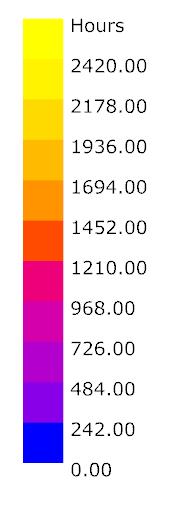
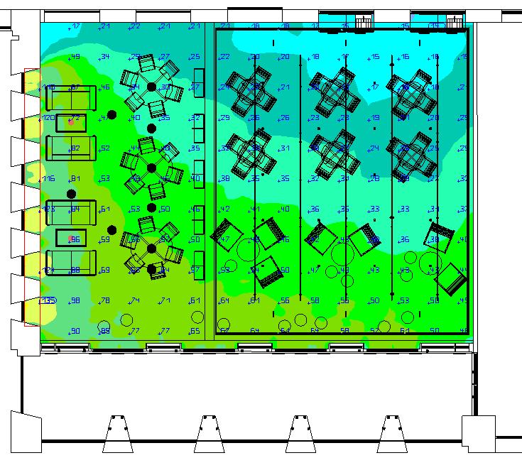
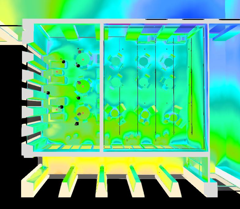
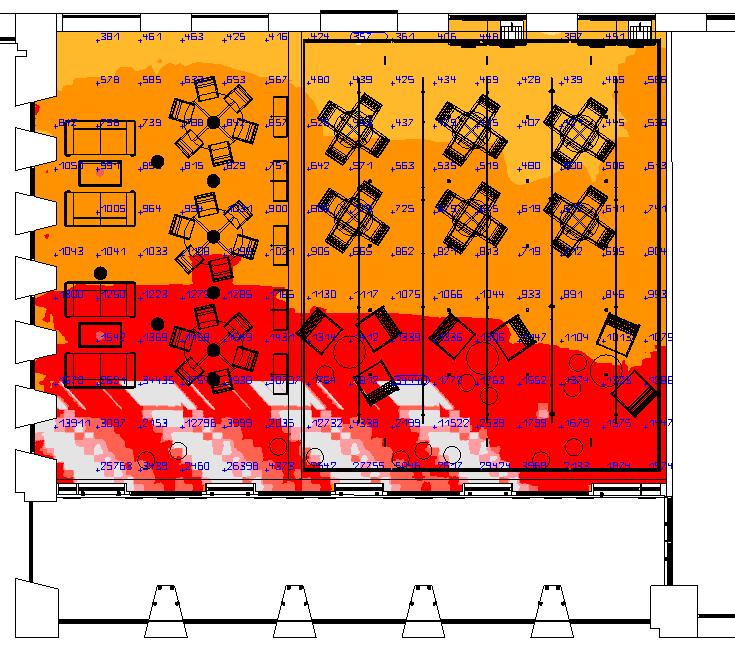
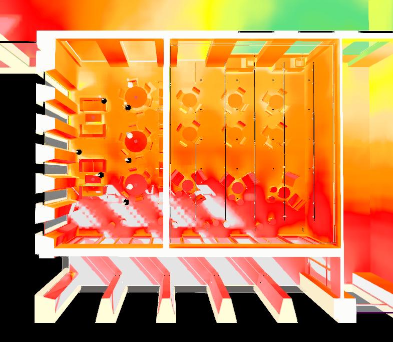
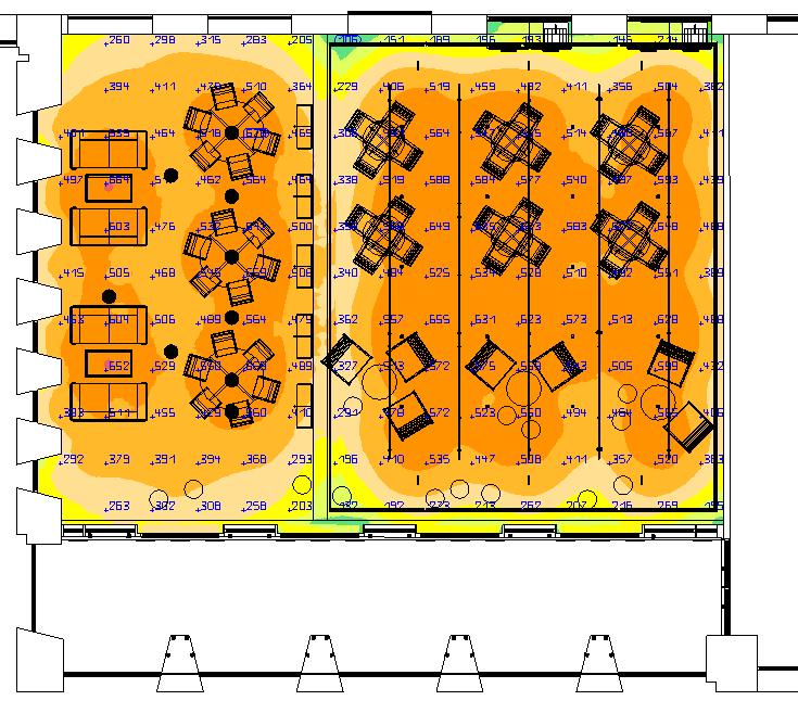
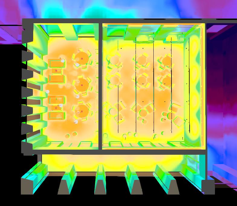
The simulation of daylight anaylsis were conducted by a simplified mpdel of UAL buildings. With general factor of all surface,t the general daylight factor is above 2.2% and the DA can reach 68%. These results shown in the diagram proves this building can harvest fairly enough dalight while working houes, which means daylight should be carefully used in the forth floor.


Combined with the daylight autonomy and daylight factor for these rooms, we know that this floor is potentially using daylight. A daylight control area of 8m was determined. Using auto-dimming, it can save up to 15% energy when areas are brighter than required.
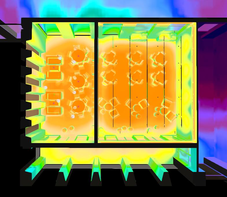
Annual sunligh hour analysis were conducted by accurated model. The south facade part of both floor 4 and the FBS Hub and received large amount of dayllight.


The central heart of the building and the rest of the rooms that form the exterior façades in lighting deisgn and control design were operated separately. This area of the 4th floor is characterized by the presence of transition areas, such as stairs, elevators and corridors, and by open and airy areas, designed and accessible to all students.
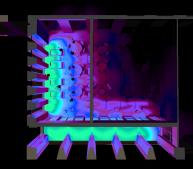
The transition areas are characterized by presence detectors that act, in the corridors by modulating the intensity of thelight and in the stairs, by turning on and off the LED stripes that light the contrast between the steps. The three central rooms are open in order to take advantage of the light coming from the skylights.
The rooms surrounding the inner heart of the building constitute the external façades. These are characterized by a diff erent need in user’s interface and therefore a distinct control strategy. In order to take advantage of daylight, we have decided to use a system of daylight linking in every room where the windows’ surface covers more than 20% of the total surface. As regards the appearance of light, we want these areas to have a different CCT, colder compared to central areas. Furthermore, the choice of luminaires has been directed towards appliances designed for school or work environments, which are not disabling.
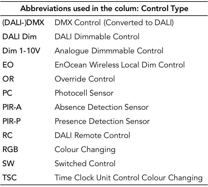
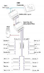
DALI is stands for Digital Addressable Lighting Interface. It is a lighting interface system that allows lighting to use a digital signal for more precise and flexible control. Using a two-way method, the system enables the user to communicate with LED drivers and ballasts, and vice versa, via a DALI controller, which is typically a computer system with software or dimming controller. DALI is also an international standard ( IEC 62386), created to ensure compatibility and interchangeability across lighting systems in the industry. In this building and also the forth floor or FBS, DALI system are working together with Building Control System to correspond the environment and time, also to create scenes among all needed areas in the building.

With increasing crossover between the entertainment, architectural and commercial lighting sectors, environments that require integration between DMX and DALI equipment are becoming more common. To convert DMX into DALI in this building of facade lighting for the exterior wall washing light, DMX to DALI is required. DMX to DALI quad converts packets from a DMX controller to DALI commands, enabling control of up to four circuits of 64 DALI ballasts each. This will achieve that DALI discovery to identify devices on the network, and enables ballasts to be controlled with the usual Broadcast, Channel, Group and Scene commands.


In the FBS Hub, the RGB linear ceiling recessed light need convert from PWN to DALI system, which can extracts dimming levels and address information from the incoming DALI data to control each of these four PWM dimming outputs individually.

 Control Design of the 4th Floor and Details of FBS Hub
Control Design of the 4th Floor and Details of FBS Hub


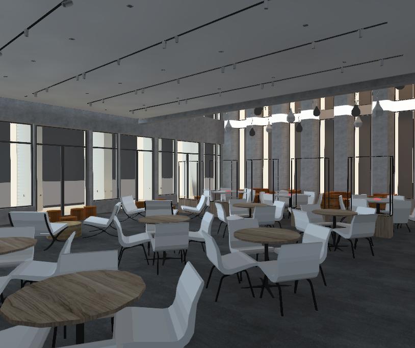
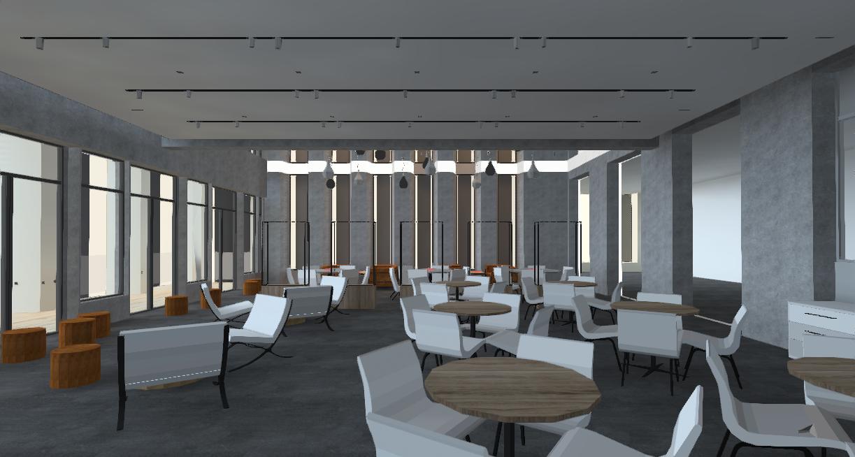
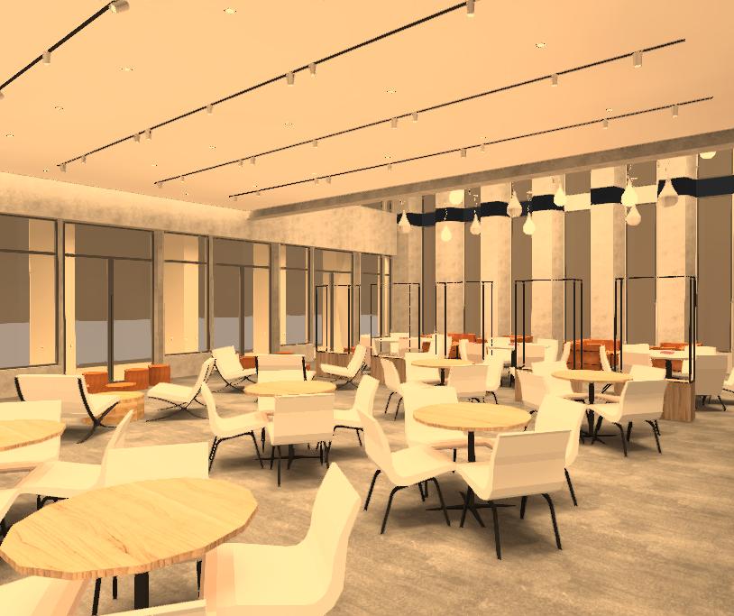
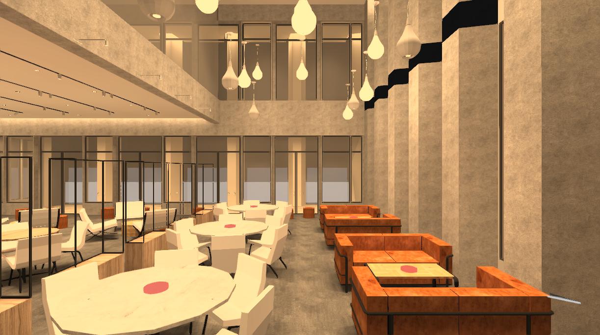
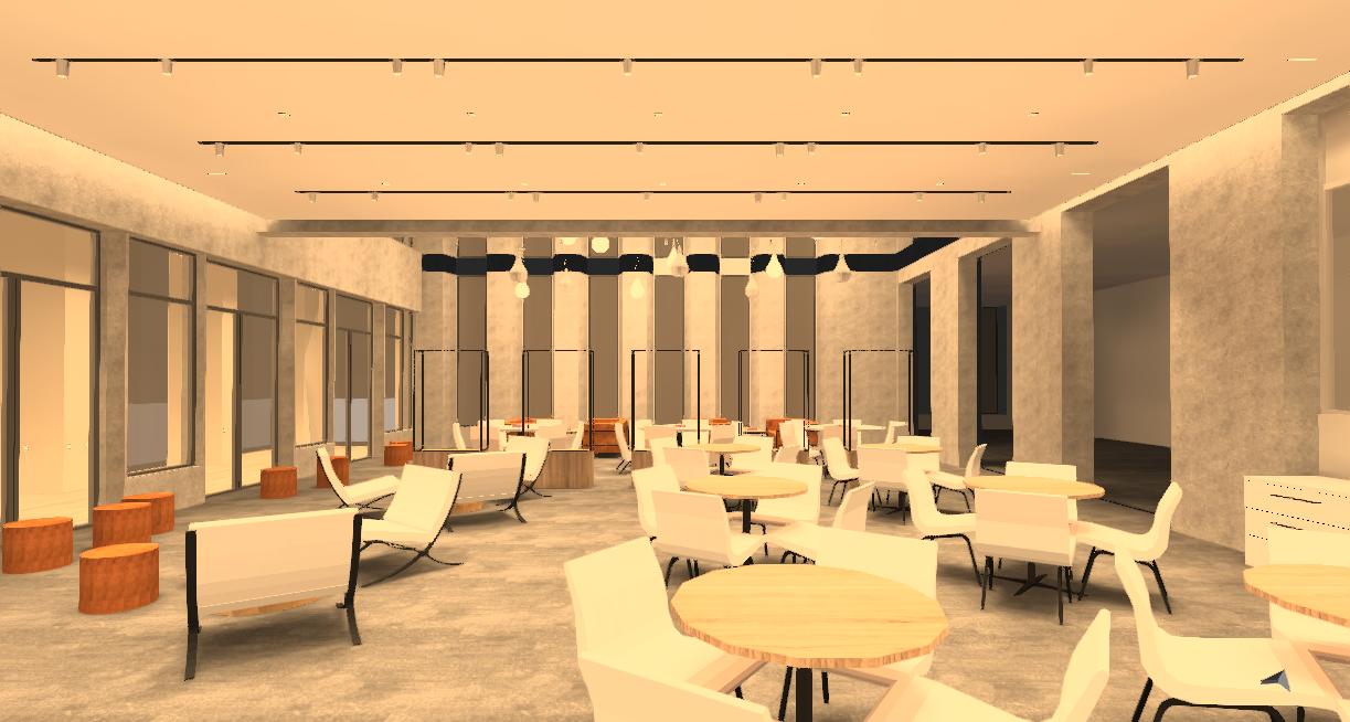
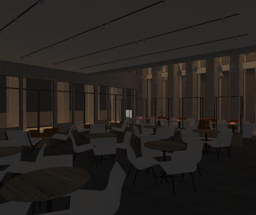
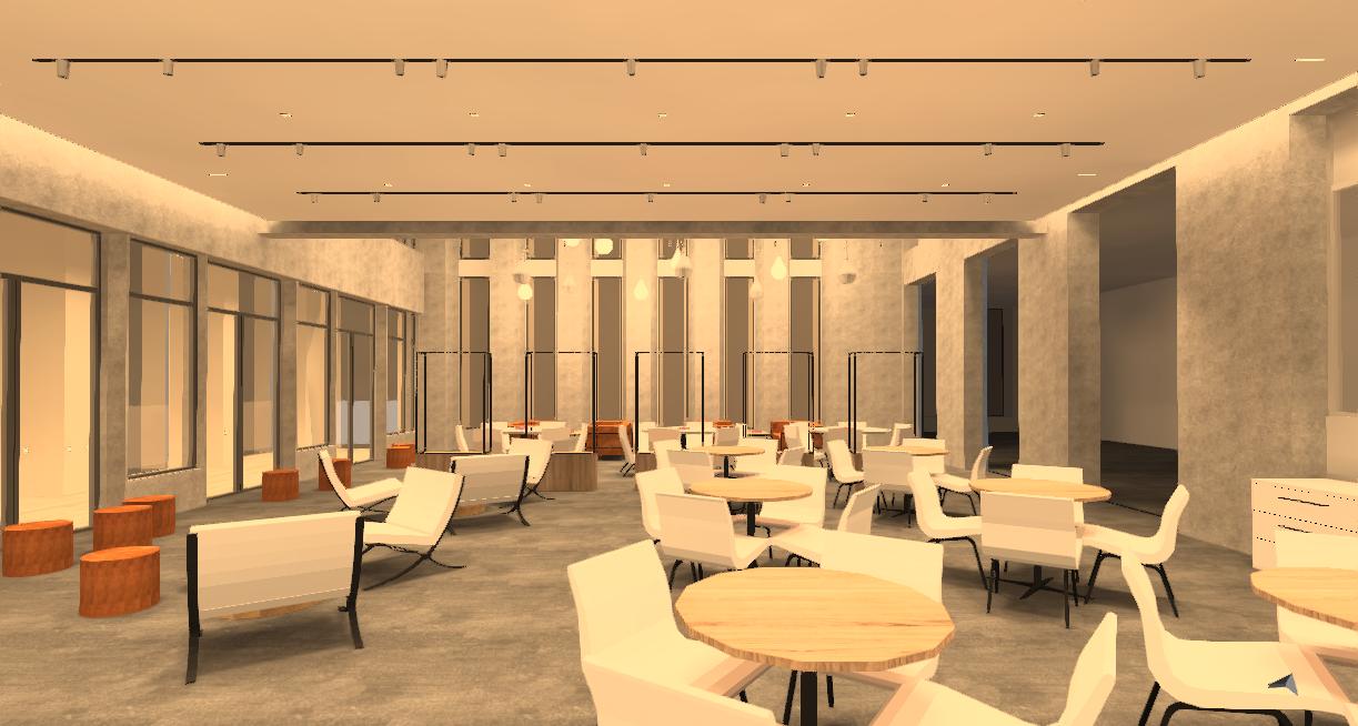
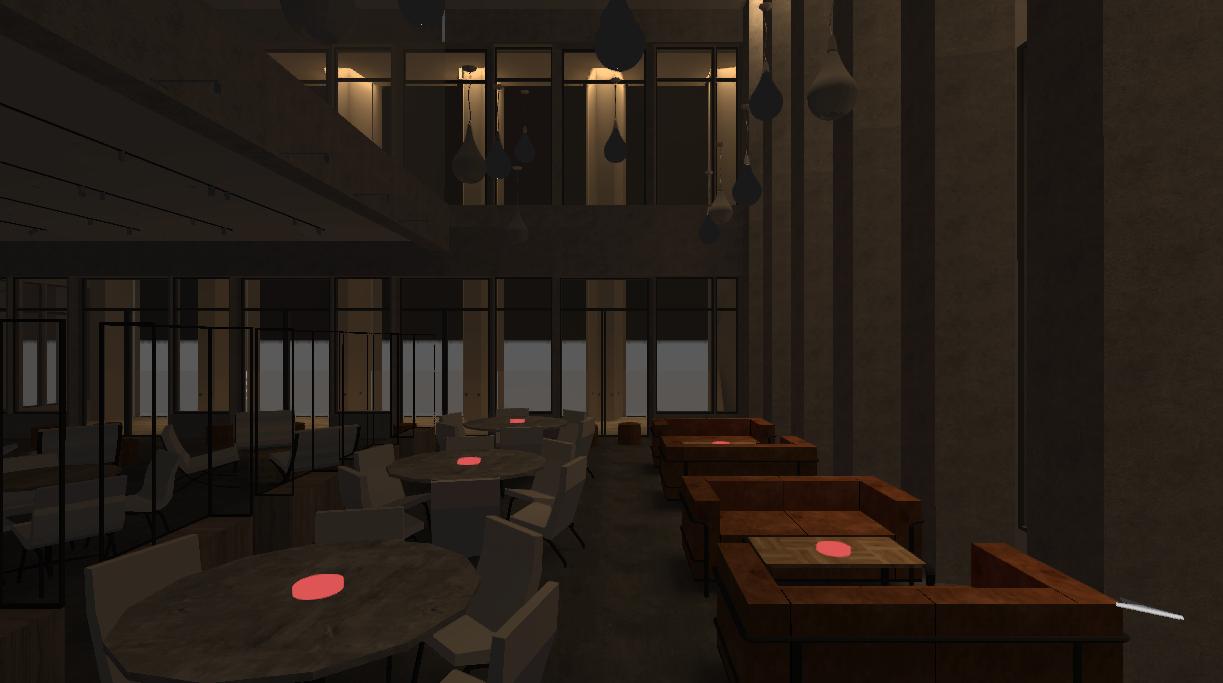
Inviting, Relaxing Vibes with high-intelligence Auto-control system, Energy saving and Easy for user to control
5.2 Layers of Designed System-1

Carefully arranged layout and output of Recessed down lights and wall light.


Control Design of the 4th Floor and Details of FBS Hub


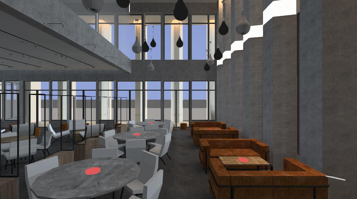
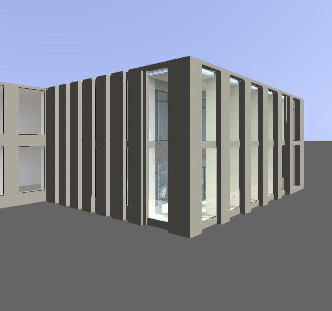
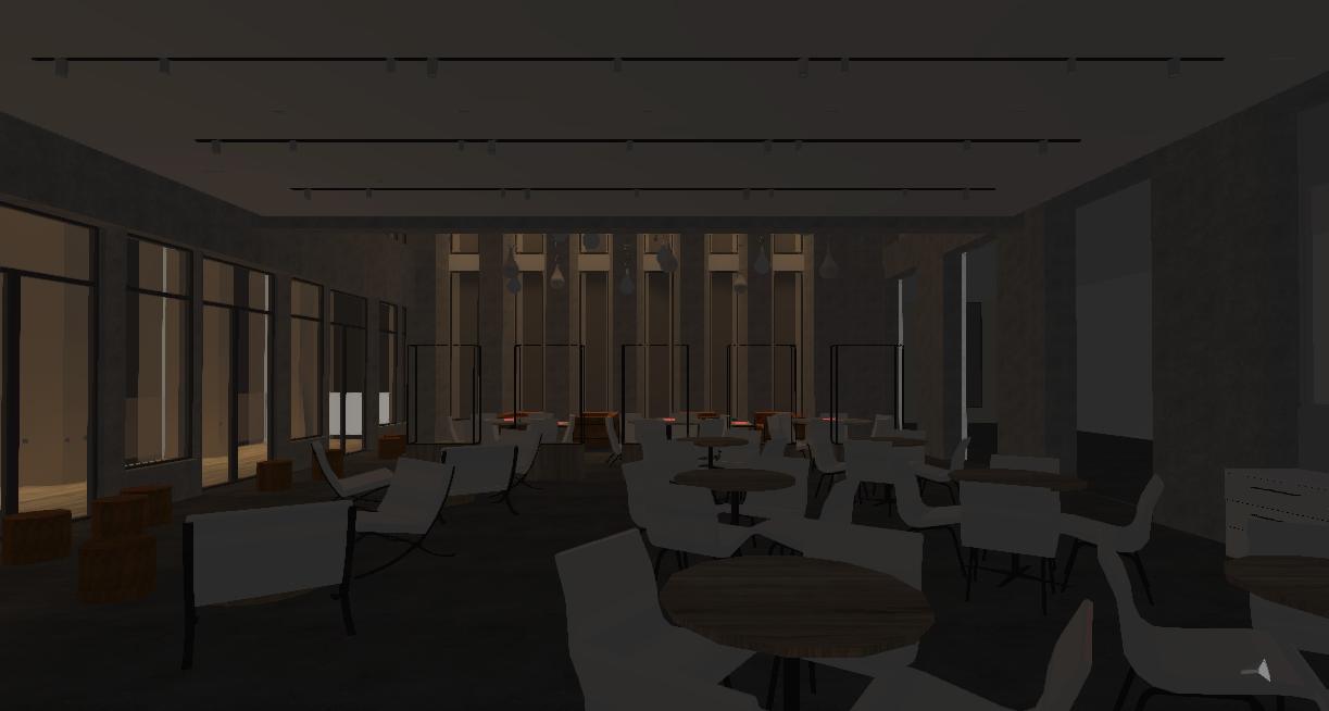
Exterior wall washers working with whole building systems for uniform appearence
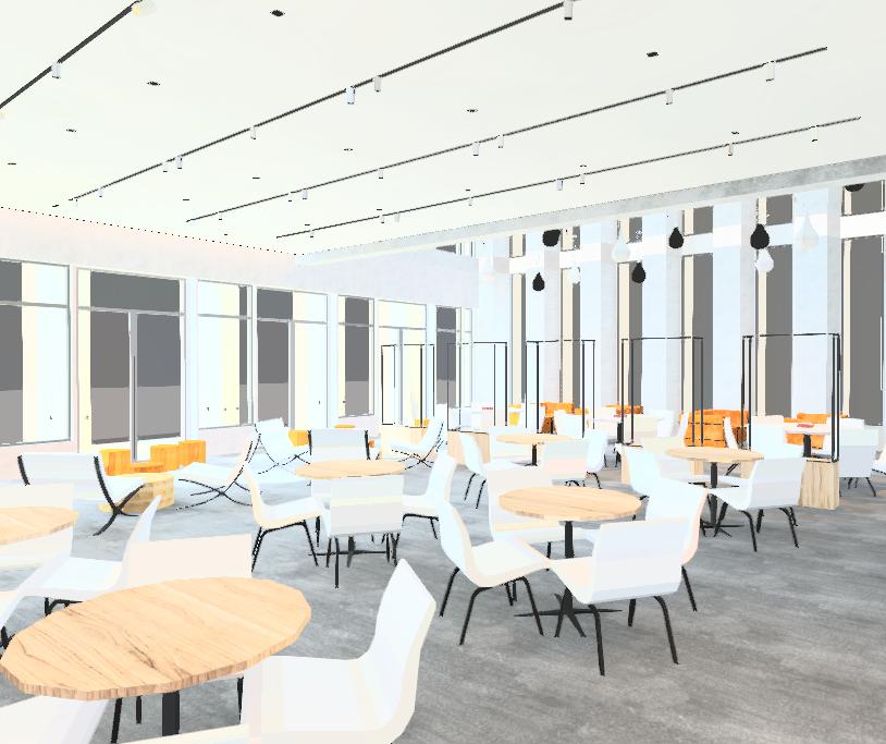
Interior wall washers to provide fizzy atmosphere
Pendant diffused light lit up all the double height space in a creative way


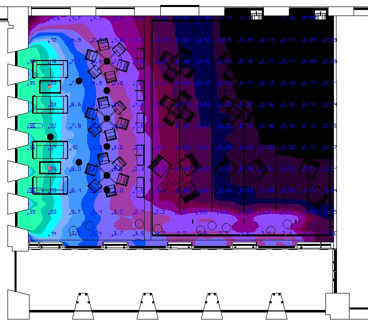
Display Planes
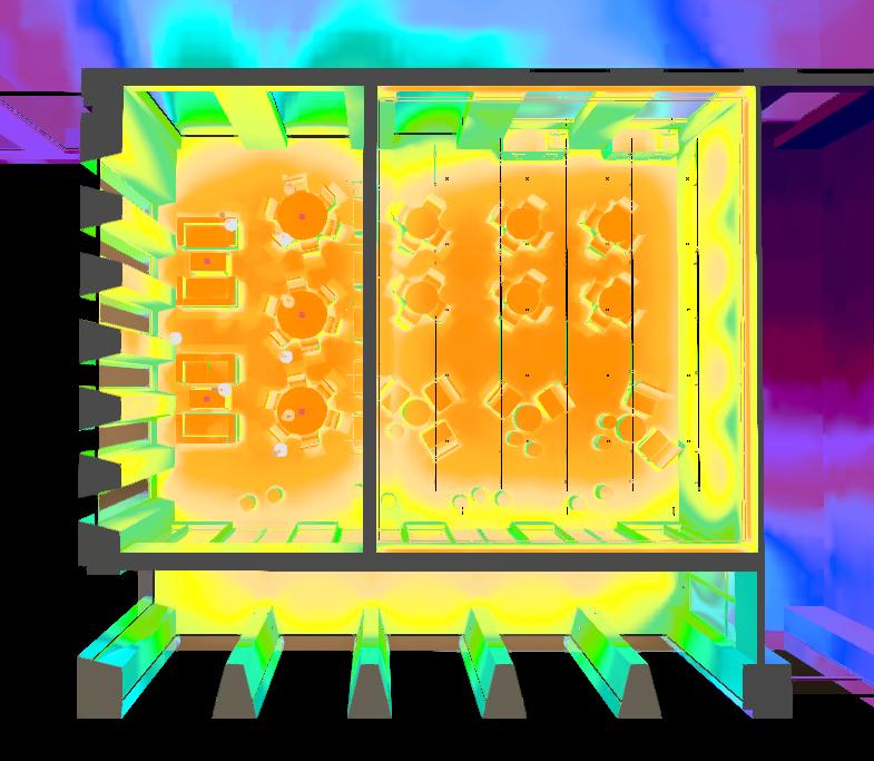
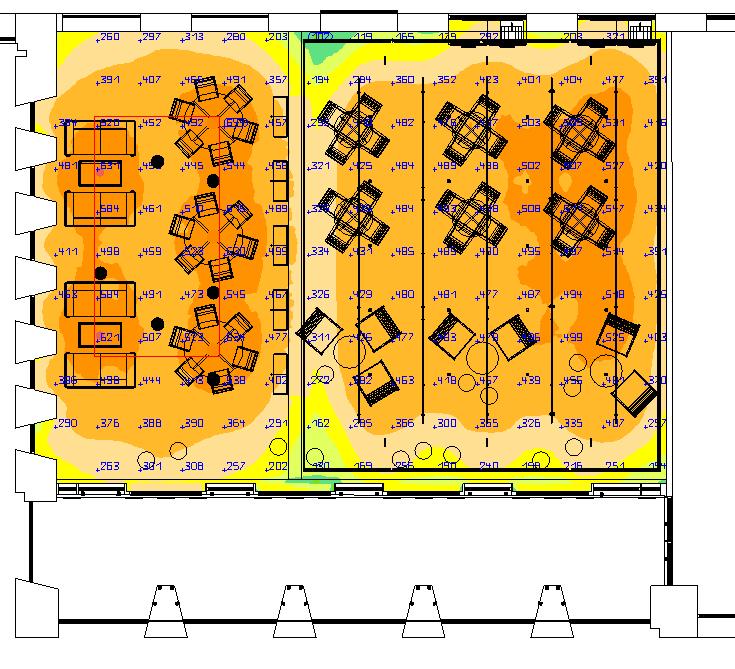
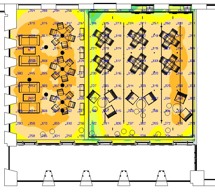
Calculation Result
Control Design of the 4th Floor and Details of FBS Hub


5.2 Layers of Designed System-3

Spot light 3 for student display in the middle part of the room
Spot light 2 for lit up the furnitures in the room
Spot light 1 for focus lighting when special events
Display Planes
Calculation Result
Control Design of the 4th Floor and Details of FBS Hub


5.2 Layers of Designed System-4
Pendant light for task lighting and creating space boarders

Exterior wall washer to create uniform safety lighting environment
Interior wall washer to help task
RGB lighting for special events

Display Planes
Calculation Result


Control Design of the 4th Floor and Details of FBS Hub
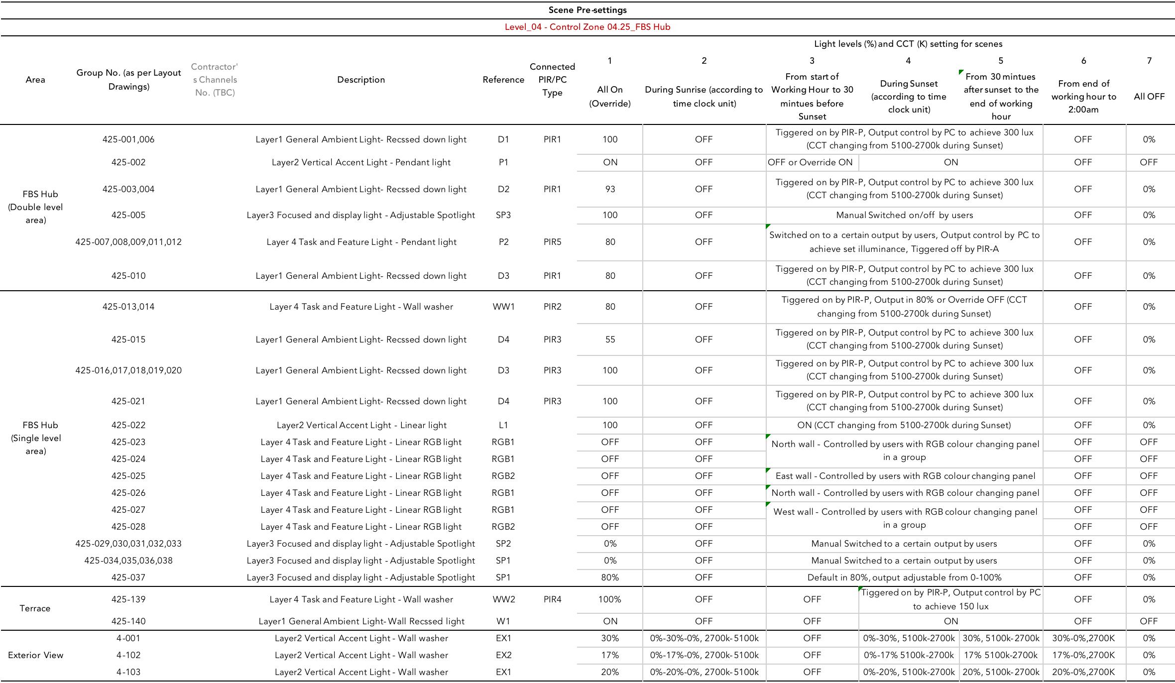
7.2.2 Scene2 - During Sunrise (according to time clock unit)
Control Design of the 4th Floor and Details of FBS Hub
7.2.3 Scene3 - From start of Working Hour to 30 mintues before Sunset FBS Hub&Terrace - Specific Scenes for Lighting Operation
Control Design of the 4th Floor and Details of FBS Hub
7.2.4 Scene4 - During Sunset (according to time clock unit)
Control Design of the 4th Floor and Details of FBS Hub

7.2.5 Scene5 - From 30 mintues after sunset to the end of working hour
Control Design of the 4th Floor and Details of FBS Hub
7.2.6 Scene6 - From end of working hour to 2:00am
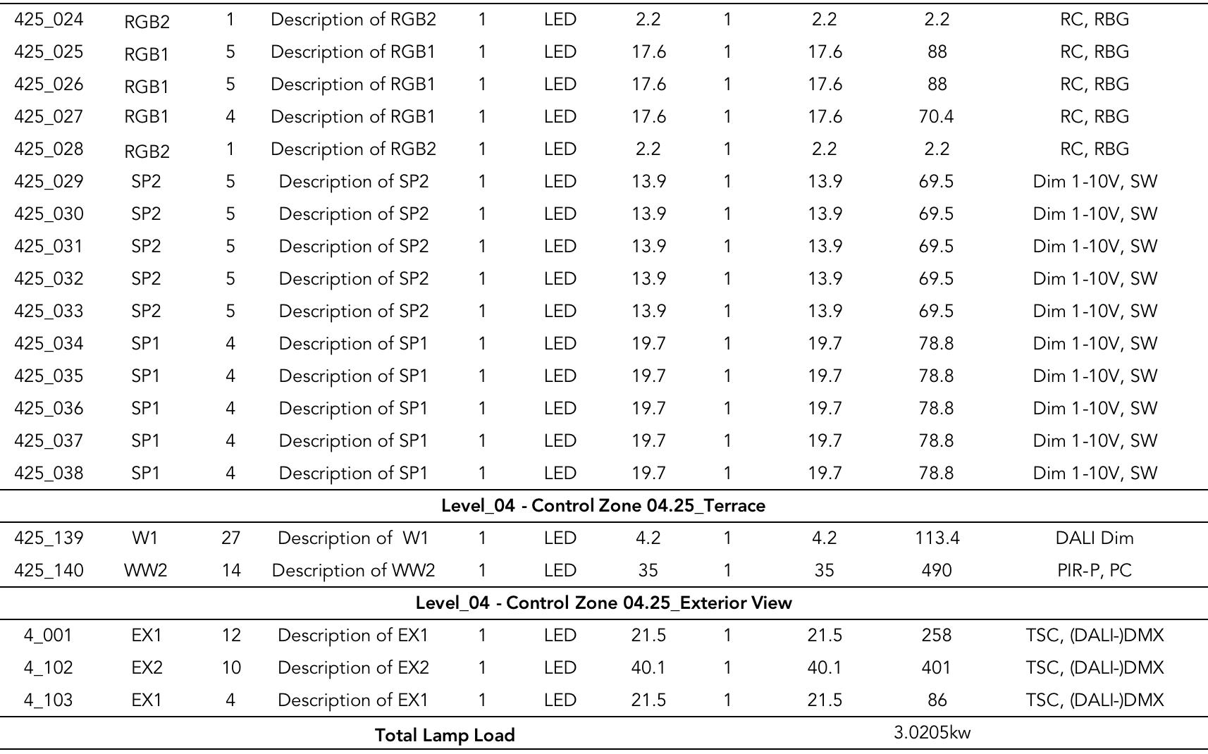
Product datasheet
Product datasheet
Electric Parameters:

Power supply DC15~30V
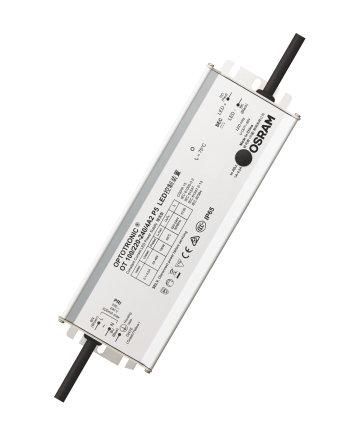
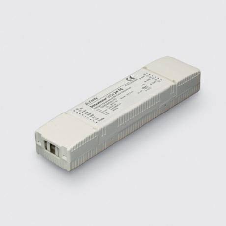
OPTOTRONIC Outdoor – Non dimmable (double/reinforced) | Constant current LED driver
Product family features
Overtemperature protection
HDL Buspro power consumption 15mA/DC24V
DALI BUS power AC220V/AC110V
Interface HDL Buspro, DALI
Environmental Cond tions:
Available with different wattage: 100 W, 150 W, 200 W
Working temperature -5℃~45℃
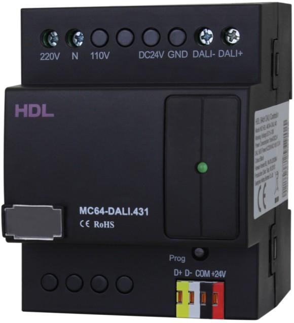
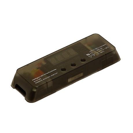
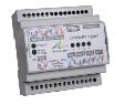
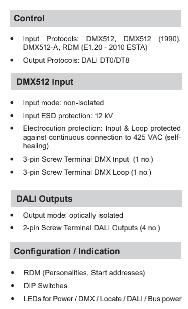
DALI Dimmer
HDL-MC64-DALI.431
Line voltage: 220…240 V
Current setting via potentiometer without programming
Working relative humidity Up to 98%
Storage temperature -20℃~+60℃
Storage relative humidity Up to 93%
Approved
CE
OPTOTRONIC Outdoor – Non dimmable (double/reinforced) | Constant current LED driver
Product family features
Overtemperature protection
Available with different wattage: 100 W, 150 W, 200 W
Line voltage: 220…240 V
Current setting via potentiometer without programming
Product family benefits
High surge protection: up to 6 kV
High efficiency
Adjustable and wide output current range
Constant current output
Protection through double isolation between primary and secondary side (SELV)
IP rating: IP65
Long lifetime: up to 100,000 h
Areas of application
Product family benefits
High surge protection: up to 6 kV
High efficiency
Adjustable and wide output current range
Constant current output
Independent installation
Street and urban lighting Industry
Suitable for luminaires of protection class I
Protection through double isolation between primary and secondary side (SELV)
IP rating: IP65

Long lifetime: up to 100,000 h
RoHS
Production Information:
Dimensions 72×90×66 (mm)
Weight 379.5g
Housing material Nylon, PC
Installation 35mm DIN rail installation
Protection degree IP20
■ HDL Buspro cable – HDL Buspro/KNX cable, 0.8mm-single core copper cable
■ HDL Buspro connect on – Recommended connection of Bus wire: hand-in-hand
■ Check Connect ons – Re-tighten all connections after installation
■ Check power wire –Make sure the power wire connects to AC terminal of module correctly
■ Ba last type – DALI
■ Check the DALI connection, There are no polar requirements for DALI Bus.
HDL Buspro Definition for Cable
HDL-MC64-DALI.431 64 channel DALI controller, it has built in DALI power supply. It is a single DALI bus, maximum 64 DALI lighting equipment.
■ Gateway between HDL Buspro system and Dali Ballast
■ Max. 64 channel Dali ballasts can be connected to this module
■ With scene control
■ Maximum 16 separate areas, supports area dimming
■ Each area has 16 scenes and Maximum scenes running time is 90.51s
■ Each channel can set low limit, high limit
■ It has built in DALI power supply and it insulates with HDL Buspro
■ You can choose specified scene or scene before power off when the device restarts
■ Short circuit protection for DALI wires
Installation Step
■ Labeling for AC power wires, DALI and HDL Buspeo wire
■ Mount the device on a DIN rail of DB
■ Connect wires for AC input of module, make sure the terminal position is correct
■
heights that are too high for general sensors
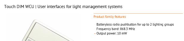
The High Bay Multisensor is a compact unit that provides energy-saving functions in DALI applications where mounting heights are too high for standard sensors, such as warehouses and factories.
Product datasheet
8.3.2 Drivers for WW2 - INS273 HB PIR (xx) DALI
Sealed with a gasket that protects it from dust and water, this IP65 sensor is designed to be recessed in a ceiling void or in a luminaire construction.


Since its detection sensitivity is less dependent on movement direction than that of most PIR sensors, fewer
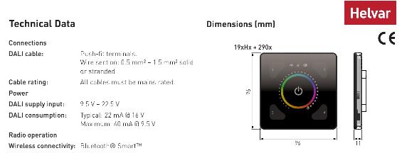
LS/PD LT2 LI UF | Sensors for light management systems
control in response to changes in space occupancy. It switches the lights on when its coverage area is
LS/PD LT2 LI UF | Sensors for light management systems
PIR sensor
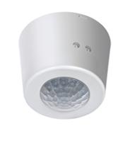
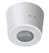
The Multisensor is a compact unit that combines a light sensor for constant light control and a passive infrared (PIR) presence detector to provide energy-saving functions in a DALI system.
The light sensor measures reflected light from the surface directly beneath it. The unit uses this information to maintain a constant light level by adjusting the lamp outputs.
The PIR sensor enables the Multisensor to switch the lights on when its coverage area is occupied, and off when it is unoccupied.


Light sensor Status LED
The sensor’s settings are adjusted using Helvar’s Designer or Toolbox software.
The High Bay Multisensor is compatible with Helvar’s lighting systems and configuration software, Designer and Toolbox.
Due to its excellent detection performance, the Multisensor is especially suitable for applications where small or slow movements take place for extended periods of time, such as offices or classrooms. Since its detection sensitivity is less dependent on movement direction than that of most PIR sensors, fewer units are required to reliably cover a target area.
• Excellent detection performance through high sensitivity and multidirectional coverage
Product family features
A light sensor, which provides a bright-out function: it can be programmed in Designer to switch off the lights when the natural light rises above a predefined illuminance threshold.
• Suitable for applications with very high ceilings
• Protected against dust and water (IP65)
The unit can be mounted into a ceiling void or onto a solid surface using Helvar’s SBB-C (white) or SBB-CB (black) mounting box (sold separately).

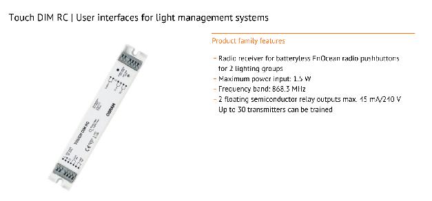
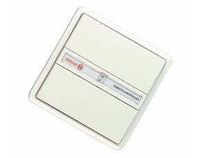
Touch DIM light and presence sensor for LEDset interface connection
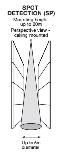
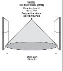
Presence Detection Coverage at 15 m Height
Product family features
Touch DIM light and presence sensor for LEDset interface connection
• Programmable bright-out control for energy efficiency*
• Simple connection and integration into a Helvar DALI control network.
Key Features
Can also be used purely as a light sensor or purely as a presence sensor
• Programmable in Designer and Toolbox
* Bright-out function is available only on a lighting router system.
• Excellent detection performance through high sensitivity and multidirectional coverage
• Programmable constant light control for energy efficiency
• 10 mA DALI current consumption
Can also be used purely as a light sensor or purely as a presence sensor
Presence Detection Coverage at 7.5 m Height
• Compact and functional design
• Programmable in Designer and Toolbox


8.6
8.6.1
C onstant vo tage power supply unit non d mmable 120W - VIN =90-305VA C 50 60H z Vout = 24V IMA X
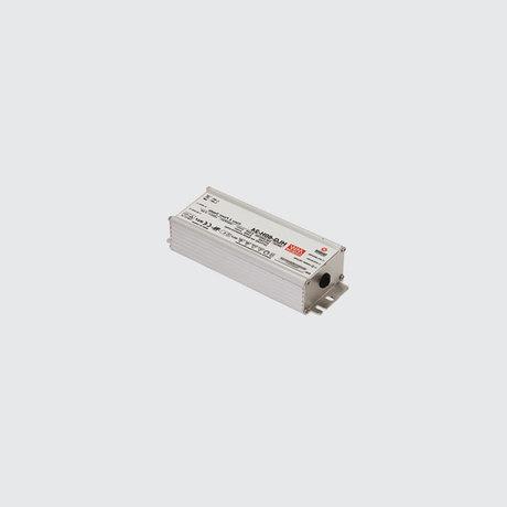
= 5A d mensions:220x68x38 8
Las nf ormat on updat e Marc h 2021
8.6.1
Accessory code
X 184: Cons an v o age power s upp y un t non d mmab e 120W - V N = 90-305V A C 50 60Hz V ou = 24V MA X = 5A

d mens ons 220x 68x 38 8
Techn ca descr pt on
uni s
B 16A : 15 powe s upp y un t s
C10A : 15 powe s upp y un t s
C16A : 25 powe s upp y un t s Ov erv o t age p o ec t on 2k V Common mode & 2k V D f erent a mode
Cons t an v o age e ec ron c power s upp y 24V dc 120W Complet e w t h ou let c ab es L= 220mm and L= 650mm V n= 90÷ 305V ac
47÷ 63Hz V out = 24V dc ± 5% out = 4 05A The produc eat u es inc ude ov e v o t age p o ec t on s hor c rc u t pro ec on, ov erc ur ent and ov ert emperat u e pro ec t on Us age t empera ure -35 °C + 70 °C
- Fo out door ns t a a ons , t he power s upp y mus t be ns er ed n a pro ec v e box ;
- he I P ra ng equ res he ins t a er o us e a s u t able prot ec t v e box
- Guz z n guaran ees t he P 66 ra ng w h a X 653 c ode ac c es s ory box
I nstal at on
The ba las t s are c omp e e wi h ho es and s lot s f or s ec ur ng t hem w t h s c rew anc hors or t hre aded s c rews
Co our nde erm na e (00) We ght (Kg) 1 2
Wi r ng
For he e ec c a c onnec on he ba as s c omp e e w t h ou e c ab es L= 220mm and L= 650mm


C o mp e s w h EN 6 0 5 9 8 -1 a n d p e t n e n t e g u a o n s
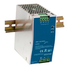
C onstant vo tage power supply unit non d mmable track D IN 240W - V N = 90-240VA C 50 60H z Vout = 24V IMA X = 10A dimensions: 63x114x125
Des gn Guzz n Guzzini
Las n ormat on updat e Marc h 2021
8.6.1
Accessory code
P C16: Cons t an v ol
Col our nde erm na e (00) C o mp e s w h EN 6 0 5 9 8 -1 a n d p e ti n e n re g u l a t o n s
For further information about all the intended accessories, please see the attached document files.*
Control Design of the 4th Floor and Details of FBS Hub
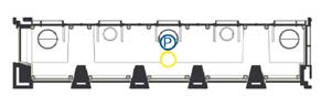
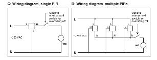
9.1 Programming of PIR & PC sensor
A. The PIR1 sensors should work together to decide all the recessed down light in the double height area if they should be on or off. As long as only one of the get the signal of people occupancy, they should turn on the light. But the output of each group should be controlled separately. The same logic applies to PIR3.
B. The PIR 4 sensors should work rogether and keep all the WW2 lights in the same condition.
C.The PIR2 signal should be able to be overrided by Local Switch.
D. The PIR5 sensors are all working along with EnOcean one light system.
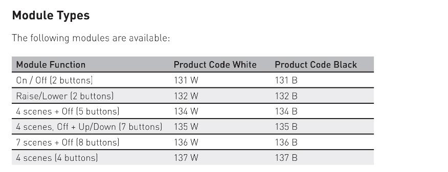
9.2 Programming of Control Panels
A. The P2 lights will have localized remote touch dim panel to set a target illuminance of that table area.
B. The RGB light on four vaiours wall should be able to be controlled separately by RGB remote 4 channel panels.
C. The SP1 and SP2 groups on a same track should be controlled by two different dimmable switches, which may need more acceessoies which are not mentioned.
9.3 Programming of Exterior Views
A. The Exterior view are created by EX1/EX2, which should be controlled with the overall building facades control channel, and to intergrated into DALI system, the conversion between DMX to DALI is required.
Attendees to include Lighting Consultant, Contractor, Control Systems supplier systems representative, - at the end of which all adjust-able fittings are aimed and all lighting controls are set. This session should take place immediately before handover, when all protective floor coverings and scaffolding are removed and all furniture and FF&E items are in place.
Attendees to include Client, Lighting Consultant, Contractor, Control systems supplier representative - at which Client comments can be incorporated into the final scheme.
Provide all access equipments as necessary for carrying out the lighting commission works.
The Contractor shall allow for the attendance during all setting up work of the lighting control system undertaken by the Control System Manufacturer/ Contractor trained personnel. The Contractor shall ensure that the control system has been fully commissioned by the Control System has been fully commissioned by the Control System Manufacture prior to this programming work.
Commissioning activities as described above may need to repeated and the Contractor shall allow for attendance, etc. for such repeat work as required by either the Lighting Consultant and / Or the Client in order to set up the lighting installation to the satisfaction of all stakeholders.
028 | AdvancedLightingControlDesign | MscLightandLighting
