


TECHNICAL PAPERS: Effects Of The Surface Roughness And The Porosity On The High Cycle Fatigue Behaviour Of Ti-6al-4v Alloy Obtained By Additive Manufacturing Process High Cycle Fatigue Behaviour Of Additive Manufactured Stainless Steel 316L: Free Surface Effect And Microstructural Heterogeneity ALSO INSIDE: INSTRUMENTATION, ANALYSIS & TESTING EXHIBITION SILVERSTONE, 16 May 2023 FATIGUE 2024 www.e-i-s.org.uk | Engineering Integrity Society Journal of the Engineering Integrity Society ENGINEERING INTEGRITY September 2022 | Issue No. 53


EV & HYBRID BATTERIES COMPONENT LIFECYCLE DURABILITY & NVH INNOVATIVE VIBRATION TESTING SOLUTIONS FOR: ROAD SIMULATION A member of the sales@dataphysics.com | dataphysics.com Dynamic Signal Analyzers Vibration Controllers Power Amplifiers Electrodynamic Shakers Service & Support Applications Experts


3 To pre-register: info@e-i-s.org.uk | www.e-i-s.org.uk ENGINEERING INTEGRITY SOCIETY Instrumentation, Analysis & Testing Exhibition Silverstone Wing, Silverstone Race Circuit 16 May 2023 10am-4pm • 60 exhibitors from aerospace, automotive, motorsport, rail, off-highway, mechanical handling, civil engineering, industrial and power generation industries. The exhibitors offer a wide variety of modern instrumentation, measuring and modelling technologies • Free Entrance to Exhibition and Mini Seminars • Free Car Parking • Complimentary Refreshments To complement the exhibition there will be a number of mini seminars throughout the day Co-sponsored by:
by


Control Cube § Controls a wide range of test machines and rigs § Scalable from single to multi-axis testing § Integrated digital signal conditioning § Portable compact design § Sophisticated - yet simple and easy to use Contact us today Tel 01568 615201 sales.uk@zwickroell.com www.zwickroell.com Technical enquiries www.cats3.com info@cats3.com § User-friendly, flexible software § Extensive range of testing applications § Integrated control, acquisition and analysis Cubus software § UK based technical support Modernise your servo-hydraulic test system with state-of-the-art digital test controllers and software Don’t be misled
its size... Packed with powerful features! Your partner in dynamic and static testing
Contents: September 2022
Index to Advertisements
Editorial
5
7
Diary of Events....................................................................................................... 8
New EIS Directors Appointed 8
News from Institution of Mechanical Engineers 9
Technical Paper: Effects Of The Surface Roughness And The Porosity On The High Cycle Fatigue Behaviour Of Ti-6al-4v Alloy Obtained By Additive Manufacturing Process................................................................... 10
Light at the End of the Tunnel
Technical Paper: High Cycle Fatigue Behaviour Of Additive Manufactured Stainless Steel 316L: Free Surface Effect And Microstructural Heterogeneity
Fatigue 2024
19
18 News from the Women’s Engineering Society
20
27
Inspiring the Next Generation
33
32 Instrumentation, Analysis & Testing Exhibition 2022
Call for Papers 34

News from British Standards 35
Industry News
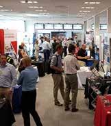
University of Wolverhampton Racing
36
40
Product News....................................................................................................... 42
Group News
47
Corporate Members 48
Committee Members
Corporate Member Profiles 52
If you would like to receive this journal electronically, please contact the Marketing & Events Manager: info@e-i-s.org.uk
...................................................................................
....................................................................................................................
.......................................................................
.........................................
......................................................................
........................................................................................................
......................................................................
...........................
......................................................................................................
.........................................................
..........................................................................................................
49
INDEX TO ADVERTISEMENTS Advanced Engineering 31 CATS3 / Zwick ...................... 4 Data Physics ....................... 2 Delta Motion .................... 18 EIS IA&T Exhibition .......... 3 EIS Reducing Doubt ...... 45 EIS Young Engineers ..... 31 Evolution Measurement .. 45 Fatigue 2024 27 HEAD acoustics ............... 55 M&P International .......... 56 Sensors UK ....................... 32 Star Hydraulics ................ 39
HONORARY
Dr Spencer Jeffs
EDITOR
E-mail: s.p.jeffs@swansea.ac.uk
MANAGING EDITOR
Rochelle Stanley
Tel. +44 (0)7979 270998
E-mail: managingeditor@e-i-s.org.uk
MARKETING & EVENTS MANAGER
Sara Atkin
Engineering Integrity Society
6 Brickyard Lane, Farnsfield, Notts., NG22 8JS
Tel: +44 (0)1623 884225
E-mail: info@e-i-s.org.uk WWW: www.e-i-s.org.uk
EDITORIAL POLICY
Engineering Integrity contains various items of information of interest to, or directly generated by, the Engineering Integrity Society. The items of information can be approximately subdivided into three general categories: technical papers, topical discussion pieces and news items. The items labelled in the journal as technical papers are peer reviewed by a minimum of two reviewers in the normal manner of academic journals, following a standard protocol. The items of information labelled as topical discussions and the news items have been reviewed by the journal editorial staff and found to conform to the legal and professional standards of the Engineering Integrity Society.
COPYRIGHT
Copyright of the technical papers included in this issue is held by the Engineering Integrity Society unless otherwise stated.
Photographic contributions for the front cover are welcomed.
ISSN 1365-4101/2022
The Engineering Integrity Society (EIS) Incorporated under the Companies Act 1985.
Registered No. 1959979
Registered Office: c/o Hollis & Co., 35 Wilkinson Street, Sheffield S10 2GB Charity No: 327121
ADVERTISING RATES & DATA
‘Engineering Integrity’ is published twice a year
Black and White
1 insert 2 Inserts
Full Page £255 £460 annual
Half Page £158 £285 annual
Quarter Page £92 £175 annual
Full Colour
1 insert 2 Inserts
Full Page £445 £800 annual
Half Page £278 £500 annual
Quarter Page £160 £290 annual
Full Page 297mm (depth) x 210mm (width) and 3mm bleed
Half Page 255mm (depth) x 86mm (width) or 125mm (depth) x 180mm (width)

Quarter Page 125mm (depth) x 86mm (width)
Space is limited so place your order soon to avoid disappointment.
A copy of the latest issue of ‘Engineering Integrity’ is published on the website and includes all advertisements.
Loose Inserts £150 per A4 sheet (up to 160 gsm)
PRINCIPAL ACTIVITY OF THE ENGINEERING INTEGRITY SOCIETY
The principal activity of the Engineering Integrity Society is the arrangement of conferences, seminars, exhibitions and workshops to advance the education of persons working in the field of engineering. This is achieved by providing a forum for the interchange of ideas and information on engineering practice. The Society is particularly committed to promoting projects which support professional development and attract young people into the profession.
‘Engineering Integrity’, the Journal of the Engineering Integrity Society is published twice a year.
‘Engineering Integrity’ is lodged with the Agency for the Legal Deposit Libraries on behalf of the Bodleian Library Oxford University, the Cambridge University Library, National Library of Scotland, National Library of Wales and Trinity College Dublin.
6
Editorial
Dr Spencer Jeffs, Honorary Editor

Let’s hope that in future editorials we will paint a brighter and steadier global picture.
The Instrumentation, Analysis and Testing Exhibition took place in May at Silverstone, which was a great success, praised by both exhibitors and attending delegates. We are already beginning plans for the 2023 exhibition. The dates for the EIS Fatigue 2024 conference, the 9th in the series, have been announced, with the conference taking place on 19–21 June 2024 at Jesus College, Cambridge, UK. I am looking forward to reading the excellent contributions from the EIS and wider community.
Welcome to the Summer 2022 edition of the Engineering Integrity journal.
I have been in this role as the Honorary Editor for the EIS journal for over two years now and it seems that we have been going through a variety of national and international crisis throughout; from war in Ukraine, the COVID-19 pandemic and its ongoing impact to extraordinary energy prices, inflation rates and the huge rise in the cost of living. Amongst this, for the UK, a new prime minister is due to be announced, with the outcome in the hands of approximately 200,000 Conservative Party members, which is less than 1% of the UK population. Whoever wins, they will be called upon to take rapid action to tackle these challenges. The results will have been completed by the time this journal is available.
Throughout July, we have seen record-breaking temperatures across the planet, with a temperature of 40.3°C seen at Coningsby, Lincolnshire, in the UK. This led to surges in fires, rail service cancellations, water shortages and health warnings. Subsequently this leads to hosepipes bans and droughts being declared along with an increase in flash flooding risk due to the dry ground. It is often considered that this record heat would provide us with soaring solar power, however for the most efficient solar power generation it is irradiance rather than heat that is more important. Elizabeth Donnelly, CEO of the Women’s Engineering Society, provides further reflection on these record temperatures within this issue.
The Farnborough International Air show returned this summer, the first since 2018, and saw announcements of aircraft orders such as those from Boeing and Airbus, perhaps indicating a steadying aerospace sector. A series of future collaborations and partnerships in the field of all-electric and hydrogen–electric propulsion system programmes were revealed. These will no doubt bring some exciting research prospects as they develop. Also, it was great to see that the electric car battery plant to be built by Britishvolt in Northumberland has had its government funding approved. This is some good news for the automotive sector, which has ongoing difficulties with skills shortages, rising energy prices and computer chip supply chains.
Two technical articles are found in this issue with a common theme, investigating the high cycle fatigue behaviour of additively manufactured metallic materials. Both articles have a focus on the influence of surface characteristics and highlight the challenges of additive manufacturing as it aims to transition from research and development into longterm full-scale industrial application, something that has come a long way over these last decades.
Universities are readying themselves for A-level results, with a record number of applications this year. With grades now coming from exams rather than teacher assessments it has led to the expectation that after two years of record results, overall grades will be lower. The Department for Education has said that University entry requirements will have to take into account that grades will be lower, but how this will actually be done is not entirely clear. I wish all those receiving grades (and their family and friends), whether A level, BTEC or T level, the best of luck and that you find a career path or university place that is right for you.
Spencer Jeffs
7
Diary of Events
EIS Committee Meetings | October 2022 (online)
COMPETITION | Peter Watson Prize, Kilworth House | 6 October 2022
EXHIBITION | Advanced Engineering, NEC, Birmingham | 2 & 3 November 2022
SEMINAR | Reducing Doubt in Engineering Measurement & Analysis, AMRC, Sheffield | 17 November 2022
EXHIBITION | Instrumentation, Analysis and Testing Exhibition, Silverstone Race Circuit | 16 May 2023
CONFERENCE | Fatigue 2024, Cambridge | 19–21 June 2024
New EIS Directors Appointed
The Directors of the EIS have been reviewing the skills and experience of the current Board with the aim of ensuring the long-term strength of the EIS.
As a result, we are pleased to announce the appointment of two new Directors: Dave Fish and Alex O’Neill. Other appointments may be made in the future as needs and opportunities arise.
Dave Fish of JoTech Ltd has been a member of the Society for many years and chairs the Sound Vibration and Product Perception Group. Alex O’Neill of Siemens has been active within the society for several years having first presented at


a seminar at HORIBA MIRA when he was studying for his PhD. He went on to win the Peter Watson Prize in 2019 and has been a great advocate of our Young Engineers Forum.
We look forward to working with Dave and Alex over the coming years and thank them for the valuable work they undertake on behalf of the Society.
8
News from the Institution of Mechanical Engineers

Paper battery powers single-use electronics – just add water Water and electronics do not generally mix, but a new disposable paper battery relies on it for activation.
Designed to power a range of low-power, singleuse disposable electronics – such as smart labels for object tracking, environmental sensors and medical diagnostic devices – the battery was developed by Gustav Nyström and colleagues at the Swiss Federal Laboratories for Materials Science and Technology (Empa).
The device is made of 1cm2 cells consisting of three inks printed onto a rectangular strip of paper. Sodium chloride salt is dispersed throughout the paper, which is dipped in wax at one end. An ink containing graphite flakes acts as the cathode on one side, while an ink containing zinc powder acts as an anode on the reverse side. An ink containing graphite flakes and carbon black is also printed on both sides of the paper, connecting the positive and negative ends to two wires at the wax-dipped end.
When a small amount of water is added, the salts within the paper dissolve and charged ions are released. The ions activate the battery by dispersing through the paper, resulting in the zinc at the negative end releasing electrons. Attaching the wires to an electrical device closes the circuit so that electrons can be transferred from the negative end to the positive end, where they are transferred to oxygen in the surrounding air. These reactions generate an electrical current that can power a device.
The researchers demonstrated their creation by combining two cells into a battery that powered an alarm clock with a liquid crystal display.
Analysis of a one-cell battery showed that after two drops of water were added, the battery activated within 20 seconds. When not connected to an energyconsuming device, it reached a stable voltage of 1.2V, slightly less than a standard AA alkaline battery on 1.5V. After one hour, the one-cell battery’s performance decreased significantly due to the paper drying, but two more drops of water brought back a stable operating voltage of 0.5V for another hour.
The biodegradability of paper and zinc could help minimise the environmental impact of disposable, low-power electronics, the researchers said. They aim
to boost the sustainability further by minimising the amount of zinc used within the ink.
Phil Peel has been an IMechE member since his student days in the early 1980s, and right through a distinguished career working on steam turbines for GEC, Alstom and now General Electric, on projects such as the nuclear new build at Hinkley Point C. But his involvement in the Institution kicked up a gear when he moved to Switzerland in 2002 – he helped to set up a local group there, and used that as a springboard to join the trustee board in 2016.
“We’re in our 175th anniversary year and I think that’s a great opportunity for us to really celebrate the achievements the Institution has made over that time. But it also gives us an opportunity to reflect on the future. One thing I think is really critical for us is to look at our strategy and focus and make sure we’ve got that well-grounded to provide a basis for us moving forward.
“We’ve got four pillars that we’ve identified: inclusion, integrity, innovation and impact. We’ve also identified seven strategic enablers that will really allow us to roll out that strategy. So there are going to be quite a lot of activities centred around strategy and implementation over the coming years, and I see my presidential year as a good opportunity to get a solid base to build on for the future.”
The research was published in ScientificReports .
New IMechE President Phil Peel Appointed
9
Technical Paper:
Effects Of The Surface Roughness And The Porosity On The High Cycle Fatigue Behaviour Of Ti-6al-4v Alloy Obtained By Additive Manufacturing Process
Viet-Duc Le1, Etienne Pessard1, Franck Morel1 and Serge Prigent2
1 Arts et Metiers Institute of Technology, LAMPA, HESAM Université, Angers, France
2 IRT Jules Verne, Bouguenais, France
Corresponding Author: Viet-Duc.LE@ensam.eu
Abstract
This work focuses on the influence of defects, including porosity and surface roughness, on the high cycle fatigue behaviour of the Ti-6Al-4V titanium alloy fabricated by the Laser Power Bed Fusion (LPBF) Additive Manufacturing (AM) process. In particular, the scatter and the statistical size effect are investigated. A vast fatigue test campaign has been undertaken, including two surface conditions (as-built and machined surfaces), and two specimen geometries. It was shown that a variety of crack initiation mechanisms, related to not only the pore type (gas and LoF pore) but also to the defect spatial position (surface or in-bulk) is the principal origin of the fatigue scatter for machined specimens. For the statistical scale or size effect, i.e., the change in the fatigue strength as a function of the loaded volume, it was shown that the changes in damage mechanisms are the first-order factor that governs the size effect observed for the machined specimens. For the as-built specimens, these effects are less significant. In the last section, two fatigue strength modelling approaches that take into account both defect types are proposed.
Introduction
One of the most challenging problems in metal Additive Manufacturing (AM) is related to the presence of defects in the materials, which can be the origin of fatigue failures in structural components subjected to cyclic loads. The two main defect types found in AM materials are surface roughness and porosity. It has been shown in the literature that the presence of these defects significantly reduces the fatigue strength of the materials (Chan et al. [1], Greitermeier et al. [2], Günther et al. [3],Wycisk et al. [4]). In the work of Günther et al. [3] and Chastand et al. [5], the authors showed the presence of different pore types from which fatigue crack initiates such as Lack-of-Fusion (LoF) pores or gas pores. It is also shown that the fatigue behaviour corresponding to these pore types are very different. Regarding the effect of the as-built surface rougness on the fatigue behaviour, a detrimental impact has been observed on the fatigue behaviour with a decrease in
the fatigue strength of up to 60% in comparison with machined specimens (Vayssette et al. [6], Nasab et al. [7], Masuo et al. [8]). The principal objective of this paper is to contribute to the comprehension of the effects of surface roughness and porosity, found in the Laser Powder Bed Fusion (LPBF) additively manufactured Ti6Al-4V titanium alloy on the fatigue behaviour in the high cycle fatigue regime. In particular, the fatigue scatter and the statistical scale effect are investigated by highlighting the roles of defect type, defect size and defect spatial location. In the second part of the article, two fatigue modelling approaches are developed to predict the effects of the two defect types, the surface roughness and the porosity, on the fatigue strength.
Specimen Fabrication
The titanium alloy used in this work is grade 23, Ti6Al-4V ELI, with a standardized chemical composition by weight of Al 6%, V 4%, C ≤ 0.08%, Fe ≤ 0.25%, H ≤ 0.012%, N ≤ 0.05% and O ≤ 0.13%. The powders have a particle size range from 20 µm to 63 µm with a median size of 43 µm. The fatigue specimens were manufactured using a SLM 280HL machine with a standard parameter set, recommended by the machine manufacturer. In total, 68 fatigue specimens, distributed in four configurations, were fabricated (Table 1). The two specimen geometries used (Standard size and Small size) are shown in Figure 1. They have very different highly loaded volumes in order to investigate the statistical scale effect. For information, the V80% (highly loaded volume in which the lowest stress is equal to the 80% of the highest stress in the whole specimen) under uniaxial tensile loads corresponding to these two geometries are respectively 2044 mm3 and 206 mm3.
Configuration (specimen size / surface state) Number of specimens
Standard size / Machined 20
Small size / Machined 19
Standard size / As-built 14
Small size / As-built 15
Table 1: Four fatigue specimen configurations.
10
ENGINEERING INTEGRITY, VOLUME 53, SEPTEMBER 2022, pp.10–17. ISSN 1365-4101/2022
All of the specimens were fabricated vertically (i.e., with a building direction of 90°). A post-heat treatment (annealing at 850 °C for 2 hours followed by slow cooling) was used to relieve residual stresses. For the machined specimens, the as-fabricated gauge diameters were 10 mm for the standard size specimens and 7 mm for small size specimens. After machining 1 mm from the radius, the gauge diameters of the machined specimens were the same as the as-built specimens.
Microstructure, porosity and surface roughness


The microstructure, observed by using an optical microscope on chemically etched samples, was columnar with the grains orientation parallel to the building direction. This is in good agreement with work from literature (Thijs et al. [9], Le et al. [10]). For the as-built specimens, the microstructure in bulk was similar to that of the machined specimens. However, a sub-surface ring of 400 µm to 500 µm in thickness with a higher microhardness than the material in bulk (440 Hv0.2 versus 370 Hv0.2) was observed, probably due to the contouring strategy used in the specimen fabrication.
In terms of porosity, two types of pore were observed: gas pores and LoF pores, as shown in Figure 2a and Figure 2b. While gas pores were generally spherical with a size between 10 µm and 50 µm (in terms of √area), LoF pores, related mainly to the balling effect (Kasperovich and Hausmann [11], Le et al. [10]), have a very spreadout geometry and can be up to 350 µm in size.

The surface roughness was characterised using an optical 3D profilometer. A scan of an as-built surface is illustrated in Figure 2c in which un-melted particles (in red) and local surface valleys (in dark blue) can be seen. The global surface roughness, evaluated in zones with a size of 20 mm x 1 mm for standard size specimens and 6 mm x 1mm for small size specimens, is approximatively Sa=10µm for all of the as-built configurations.
Fatigue Behaviour And Damage Mechanisms
All fatigue tests were carried out at ambient temperature and pressure in laboratory air. The fatigue tests were conducted with a constant stress amplitude, a load ratio of R=0.1 and a frequency of 20 Hz. Tests were stopped after 2x10⁶ cycles. The run-out specimens that survived 2x10⁶ cycles were re-tested at a higher load. The principal aims of the re-tests is to gain access to the critical defect for all of the specimens in order to obtain a large enough database with a limited number of specimens. Because only the specimens that survived 2x10⁶ cycles were retested, the authors supposed that strengthening or cumulative damage effects are not significant at such a high number of cycles.
The Wöhler curves of the four configurations are shown in Figure 3. The fitting curves corresponding to a probability failure (Pf) of 10%, 50% and 90% were calculated using the Stromeyer equation [12], given as follows.
(1)
where Nf is the number of cycles to failure, S max is the maximum stress, S0 is the fatigue limit. C and m are material parameters.
 Figure 2: a) A gas pore, b) a LoF pore observed by X-ray micro-tomography and c) As-built surface topography scanned by a 3D profilometer.
Figure 1: Two fatigue specimen geometries: Standard size and small size.
Figure 2: a) A gas pore, b) a LoF pore observed by X-ray micro-tomography and c) As-built surface topography scanned by a 3D profilometer.
Figure 1: Two fatigue specimen geometries: Standard size and small size.
11
It can be seen that for the machined specimens, the scatter of the fatigue strength at 2x10⁶ cycles is relatively high with a covariance, defined as the ratio between the standard deviation (Std) and the mean value (SD) of the fatigue strength, of between 12% and 16%. Furthermore, it appears that the data are grouped into two different populations that are especially clear for the small size machined specimens. The first population, on the left of the diagram, includes points with Nf lower than 105 cycles, even for low applied stresses. The second population on the right includes specimens that have much higher fatigue lives with Nf between 105 and 2x10⁶ cycles. For the as-built specimens, the scatter in the S-N data is much lower, with a covariance between 5.5% and 8.6%. By comparing the fatigue strengths at 2x10⁶ cycles, it can be seen that the fatigue strength of the as-built specimens is approximately 40% to 60% lower than that of the machined specimens.
Regarding the scale effect, by comparing the fatigue strength at 2x10⁶ cycles, it can be stated that the fatigue strength of the small size specimens is higher than the standard size specimens (700 MPa vs 500 MPa). For asbuilt specimens, the scale effect is less significant.


Observations of the fatigue failure surfaces of all of the tested specimens using a scanning electron microscope reveal a large variety of crack initiation mechanisms. For the machined specimens, four mechanisms were identified: 1) LoF pores at the free surface (Figure 4a); 2) LoF pores in the bulk (Figure 4b); 3) Gas pores at the free surface (Figure 4c); 4) Gas pores in the bulk (Figure 4d). For the as-built specimens, two crack initiation mechanisms were observed: 1) LoF pores at the free surface (Figure 4e) and 2) surface roughness without the presence of a pore (Figure 4f).

 Figure 3: Wöhler curves for (a) standard size machined specimens and (b) small size machined specimens, (c) standard size asbuilt specimens, (d) small size as-built specimens.
Figure 4: The defect types observed at the crack initiation sites: for the machined specimens, (a) LoF pore at the surface, (b) LoF pore in the bulk, (c) Gas pore at the surface, (d) Gas pore in the bulk; for as-built specimens e) crack initiation from a LoF pore and f) crack initiation from the surface roughness.
Figure 3: Wöhler curves for (a) standard size machined specimens and (b) small size machined specimens, (c) standard size asbuilt specimens, (d) small size as-built specimens.
Figure 4: The defect types observed at the crack initiation sites: for the machined specimens, (a) LoF pore at the surface, (b) LoF pore in the bulk, (c) Gas pore at the surface, (d) Gas pore in the bulk; for as-built specimens e) crack initiation from a LoF pore and f) crack initiation from the surface roughness.
12
Configuration LoF pore on surface Nb (Pct.)
LoF pore in bulk Nb (Pct.)
Gas pore on surface Nb (Pct.)
Gas pore in bulk Nb (Pct.) Surface roughness Nb (Pct.)
Standard size / Machined 10 (50%) 8 (40%) 2 (10%) 0 (0%) 0 (0%)
Small size / Machined 7 (37%) 5 (26%) 4 (21%) 3 (16%) 0 (0%)
Standard size / As-built 11 (85%) 0 (0%) 0 (0%) 0 (0%) 2 (15%)
Small size / As-built 7 (47%) 0 (0%) 0 (0%) 0 (0%) 8 (53%)
Table 2: A summary of the sample numbers with different crack initiation mechanisms in each configuration.
Analysis Of The Effects Of Defects On The Fatigue Behaviour

In order to analyse the effect of the defects on the scatter and the scale effect, a summary of the number of occurrences of each crack initiation mechanisms, observed in all batches, is given in Table 2. Furthermore, S-N diagrams in which the different crack initiation mechanisms are highlighted are shown in Figure 5a for the machined specimens and in Figure 5b for the asbuilt specimens.
It can be observed, for the machined specimens, that the fatigue behaviour corresponding to the four crack initiation mechanisms are very different. The LoF pores
(with an average mean size of 150 µm in √area) located at the free surface are the most detrimental defect type while the gas pores (with an average mean size of 30 µm in √area) in bulk seem to be the least harmful defect type. Another interesting observation is the effect of the defect spatial position. For the same LoF pore type, the pores located on the specimen surface are more detrimental than the ones in bulk, given that the pore size distributions are similar. From these observations, it can be concluded that the high scatter observed for the machined specimens is caused principally by the large variety of crack initiation mechanisms. For the as-built specimens, the S-N diagram shown in Figure 5b demonstrates that there is no significant difference in terms of the fatigue strength between the two crack initiation mechanisms. This observation is quite surprising because when linked to the defect size as illustrated in Figure 4e, the impact of a LoF pore with a depth of approximately 400 µm is equivalent to a surface roughness defect with a depth of 20 µm (Figure 4f).
Regarding the scale effect observed for the machined specimens, it can be seen in Table 2 that the probability of occurrence of LoF pores at the crack initiation sites is higher for the standard size specimens than the for the small size specimens, knowing that the LoF pore size distributions are similar. Because the fatigue strength related to the LoF pore mechanisms is significantly lower than for the other pore type (i.e. gas pores), it can be concluded that the scale effect observed for the machined specimens is linked principally to the change of the crack initiation mechanism and not to the change of the critical pore size. For the as-built specimens, the change of crack initiation mechanism can also be stated to occur. However, because of the similarity in the fatigue strengths of these two mechanisms, the scale effect is less pronounced for the as-built specimens.

Modelling Of The Fatigue Strength Taking Into Account The Defects
In this section, two fatigue modelling approaches are developed to deal with the two observed defect types, porosity and surface roughness. The first one takes into account the effect of porosity on the fatigue strength for machined specimens (i.e., without as-built surface roughness). More precisely, by using a probabilistic approach, the change in the crack initiation mechanism
Figure 5: Correlation between the fatigue strength and the fatigue damage mechanisms for a) machined specimens and b) as-built specimens.
13
when changing the loaded volume can be modelled, in combination with a model taking into account the pore size effect. The second approach models the effect of the as-built surface roughness on the fatigue strength. Even though this mechanism is not the main mechanism observed for the as-built specimens in this study, modelling of the surface roughness effect is always of interest in fatigue design. Finally, the mechanism of LoF on the surface in as-built specimens, which is the main mechanism observed for the as-built specimens, should be modelled as a combination of i) porosity effect model and ii) roughness effect model, as proposed in the work of Pomberger et al. [13]. This approach will be developed in the future and is not presented in this paper.
1st Approach: modelling the effect of porosity

The concept behind the first modelling approach is shown in Figure 6. The principal aim of this approach is to model the scale effect observed for machined specimens, which is governed principally by changes in the crack initiation mechanism and not by the change of the critical pore size distribution. For this reason, it is assumed that the critical pore size distribution, measured at the crack initiation sites, does not change as a function of the loaded volume. A deterministic model linking the mean fatigue strength SD to the pore size √area is obtained by using a corrected fatigue strength (in terms of the maximum stress) S max and the Stromeyer model, as given by Eq. (1) and (2). The model parameters are empirically obtained by fitting with the experimental S-N data. More details of this approach can be found in a previous publication (Le et al.[14]). The distribution of the fatigue strength for each crack initiation mechanism (LoF pore on surface (PDF1), LoF pore in bulk (PDF2), gas pore on surface (PDF3)) is then calculated by combining the deterministic model “√area- SD” and the critical pore size distribution.
(2)
The probability of occurrence of the three crack initiation mechanisms, LoF pore on surface (P1), LoF pore in bulk (P2) and gas pore on surface (P3), are calculated from the volume density of LoF pore, λ, defined as the number of LoF pores per mm3. Crack initiation from internal gas pores (with a probability of occurrence less than 10%) is neglected in the present approach. The volume density of LoF pore λ is determined thanks to an inverse methodology, inspired by the work of Chandran [14] and presented in detail in [15]. In short, by assuming that the spatial distribution of LoF pores is completely random, the probability of occurrence of each crack initiation mechanism is calculated for several λ values and for a given volume. The results are then compared with the probabilities of occurrence of the


Figure 7: Identification of the LoF pore density value by the inverse methodology. Curves –probability of occurrence of each crack initiation mechanism simulated; Dots – Probability of occurrence measured of each mechanism measured on failure surface.
 Figure 6: Description of the probabilistic approach to model the effect of porosity on fatigue strength.
14
(3)
Figure 8: Predicted fatigue strength distribution for a) Standard size and b) Small size with a LoF pore density λ=10-2 pore/mm3.


crack initiation mechanisms observed experimentally on the failure surfaces in order to find a reasonable λ value. As shown in Figure 7, the correlation between the simulation curves and experimental data points for the probability of occurrence of each crack initiation mechanism shows that the density of LoF pore can be estimated to be between 10-3 to 10-2 pores per mm3. A value λ = 10-2 pore/mm3 is used in the next step. Finally, the global fatigue strength distribution corresponding to a given loaded volume is calculated as the sum of the fatigue strength distributions of all of the crack initiation mechanisms. Figure 8 shows the simulated fatigue strength distributions for the standard size and the small size specimens. The experimental fatigue strengths obtained by extrapolating the S-N data to a fatigue life of 2x10⁶ cycles using Eq. (2) are also shown in order to compare with the simulated distributions.
Firstly, it can be seen that a variety of crack initiation mechanisms are taken into account in this approach, which results in more than one peak in the fatigue strength distributions. The scale effect is also predicted when comparing the fatigue strength distributions between the standard-size and small-size specimens. In fact, it can be seen that the highest peak in the fatigue strength distribution for standard-size specimens corresponds to the LoF pore on surface mechanism while for small-size specimens, the highest peak correspond to the LoF pore in bulk mechanism. This change results in an increase in the fatigue strength at a failure probability of 50% (approximately 450 MPa for the standard size and 550
MPa for the small-size specimens). Finally, it can be seen that the predicted fatigue strength distributions are in good agreement with the extrapolated fatigue strengths.
2nd Approach: modelling the effect of the surface roughness

In the literature, numerous fatigue approaches take into account surface roughness via local surface valley parameters. Two characteristics of local surface valleys that are often used to model the fatigue strength are the depth (characterized by maximum profile valley depth Rv or Sv in case of surface valley) and the valley radius ρ ( [13]). In the current work, a surface profile processing methodology has been developed in order to be able to determine these two parameters. This methodology consists of, firstly, applying tilting corrections and a Gaussian regression filter on the surface profiles extracted from surface topography obtained by a Bruker’s 3D optical profilometer. A convolution filter with a Hann window is then applied in order to convert the numerical profile to a smooth profile, which makes it possible to calculate the curvature, κ, and then the radius of curvature, ρ, at every point of the profile. The mathematical formulations of the curvature and the radius of curvature are given as follows in which x, y are the Cartesian coordinates of each point on the profile and x',x'',y',y' ' are the first and second derivatives of the coordinates.

Figure 9: Surface profile (extracted from 3D surface topography scanned by the profilometer for a) LBPF as-built surface and b) machined surface.

15
(3)
Figure 9a shows an as-built surface profile with a cartography of the radius of curvature at each point of the profile. The same diagram for a machined surface is shown in Figure 9b for comparison. It can be seen that for the LBPF as-built surface profile, the local valleys can reach 35 µm in depth while the radius of curvature at the valley bottoms is very small, can reach ρ=1 µm. For the machined surface, the local surface valleys are much more regular with lower Rv values and larger radii at the valley bottoms. From the R v and ρ values, the stress concentration factor, K t, and the notch sensitivity factor, Kf, are calculated using the Peterson approach (Peterson [16]) and the approach proposed by Lukas and Klesnil [17] (Eq. (4)). A value of the material parameter a0 of 0.01 mm is chosen so that the predicted fatigue strength distribution matches with the experimental result. The distribution of the Kf is then calculated by using the extreme value theory (Makkonen et al. [18]).
Finally, the fatigue strength (SD) distribution of the asbuilt specimens is calculated from the fatigue strength of defect-free material SD,0. Thanks to fatigue tests conducted on HIP machined specimens for which the fatigue crack initiation is linked to the microstructure without the presence of defects, a value of SD,0=720 MPa was found. A similar value is also reported in the literature ( [2], [19]) for a load ratio of R=0.1 and a fatigue life of 2x10⁶ cycles.


Figure 10 shows the distributions of Kf and the fatigue strength at 2x10⁶ cycles (SD) for machined surface and as-built surface specimens. The fatigue strengths extrapolated from the S-N data of the only as-built specimens related to the surface roughness mechanism are also shown for comparison. The predicted mean value of the Kf factor is approximately 2.25 for as-built surfaces, resulting in a fatigue strength of approximately 320 MPa, which is in good agreement with the experimental result. For machined specimens, a mean value of Kf = 1.1 is estimated, resulting in a fatigue strength approximately 10% lower than the SD,0 value. This decrease seems be over-estimated for machined surface specimens with a S a lower than 0.5 µm (Abroug et al. [20]). One possible explanation is that for very small local surface valleys, such as in a machined surface, the Lukas approach cannot take into account the “small crack” phenomenon and hence underestimates the fatigue strength. In summary, the proposed approach to model the surface roughness effect on the fatigue strength is potentially feasible for engineering fatigue design. However, further validation with different surface roughness levels are necessary to enhance the approach.
Discussion and Conclusions
This work deals with the scatter and the statistical scale effect in fatigue behaviour of a LBPF Ti-6Al-4V alloy. It is shown that the high scatter observed on the machined specimens is governed principally by the large variety of crack initiation mechanisms (LoF pores or gas pores; surface or internal pores). In fact, the fatigue strength changes significantly from one mechanism to another, for example the fatigue strength related to LoF pores on surface is more than 1.5 times lower than the value linked to gas pores. The scale effect is also pronounced for the machined specimens and can be explained by the change of the occurrence probability of each mechanism when changing the loaded volume. For the as-built specimens, these effects are much less pronounced even though there are multiple crack initiation mechanisms, which can be explained by the similarity in fatigue strengths of all of the mechanisms.
In order to model the effects of the two defect types, the porosity and the surface roughness, on the fatigue
 Figure 10: Extreme value distributions of Kf and (b) simulated fatigue strength distribution.
16
(4)
strength, two approaches have been developed. The first one models the effect of porosity by using a probabilistic approach that considers all of the crack initiation mechanisms. The model takes into account pore size and location as well as LoF pore density. Thanks to this approach, the change in crack initiation mechanism when changing the loaded volume can be simulated and hence the scale effect can be predicted. One of the key parameters of this model is the LoF pore density for which the estimation is not simple. In this work, an inverse methodology was used. This approach is not perfect because the result depends on the number of observations realised on fatigue failure surfaces, which is often not large enough to be statistically representative. Another way, would be to use tomography observations. However, it was observed in the present project that compressive residual stresses on the machined surfaces makes the surface crack initiation mechanism less likely to occur. Consequently, the use of the LoF pore density measured by tomography observations in this model results in a highly conservative predicted fatigue strength.
The second approach models the effect of surface roughness on fatigue strength. A surface profile processing algorithm has been developed to determine the depth and the radius of curvature at the bottom of local profile valleys. These two parameters are then used to calculate the notch sensitivity factor thanks to classical approaches and the associated fatigue strength. It should be noted that this model does not take into account the interaction between in-bulk pores and surface roughness and should be used when crack initiation is only related to the surface roughness. For the case where pores are present at the crack initiation sites, a mixed model that combines both developed approaches using a weight factor could be considered.
Both of these models have been validated initially with the data that was used to develop the models. Further validation with materials that have significant changes in terms of defect characteristics (such as LoF pores density for the first model; surface roughness level for the second model) needs to be done. However, both approaches that have been developed in light of the observed the crack initiation mechanisms and are potentially feasible for engineering fatigue design.
Acknowledgement
This study is part of the FASICOM project, managed by the IRT Jules Verne (French Institute of Research and Technology in Advanced Manufacturing Technologies for Composite, Metallic and Hybrid Structures). The authors wish to associate the following industrial partners with this work: ADDUP, AIRBUS, ArianeGroup and General Electric.
References
[1] Chan, K. S., Koike, M., Mason, R. L., Okabe, T., Metall. Mater.Trans. A, vol. 44, pp. 1010–1022, 10 2012.
[2] Greitemeier, D., Palm, F., Syassen, F., Melz, T., Int. J. Fatigue., vol. 94, pp. 211–217, 1 2017.
[3] Günther, J., Krewerth, D., Lippmann, T., Leuders, S., Tröster, T., Weidner, A., Biermann, H., Niendorf, T., Int.J.Fatigue., vol. 94, pp. 236–245, 1 2017.
[4] Wycisk, E., Solbach, A., Siddique, S., Herzog, D., Walther, F., Emmelmann, C., Phys.Procedia , vol. 56, pp. 371–378, 2014.
[5] Chastand, V., Quaegebeur, P., Maia, W., Charkaluk, E., Mater.Charact., vol. 143, pp. 76–81, 2018.
[6] Vayssette, B., Saintier, N., Brugger, C., May, M. E., Pessard, E., Int. J. Fatigue., vol. 123, pp. 180–195, 2019.
[7] Nasab M. H., Romano S., Gastaldi D., Beretta S., Vedani M., Addit. Manuf., p. 100918, 2019.
[8] Masuo, H., Tanaka, Y., Morokoshi, S., Yagura, H., Uchida, T., Yamamoto, Y., Murakami, Y., Int. J. Fatigue, vol. 117, p. 163–179, 12 2018.
[9] Thijs, L, Verhaeghe, F., Craeghs, T., Humbeeck, J. V., Kruth, J.-P., Materialia , vol. 58, p. 3303–3312, 5 2010.
[10] Le, V.-D., Pessard, E., Morel, F., Edy, F., Eng. Fract. Mech. , vol. 214, pp. 410–426, 2019.
[11] Kasperovich, G., Hausmann, J., J. Mater. Process. Technol. , vol. 220, p. 202–214, 6 2015.
[12] Stromeyer, C. E., Proc. R. Soc. Lond. Series A , Containing Papers of a Mathematical and Physical Character, vol. 90, p. 411–425, 7 1914.
[13] Pomberger, S., Stoschka, M., Aigner, R., Leitner, M., Ehart, R., Int.J.Fatigue., vol. 133, p. 105423, 4 2020.
[14] Chandran, K. S. R., Nat. Mater., vol. 4, p. 303–308, 3 2005.
[15] Le, V.-D., Pessard, E., Morel, F., Prigent, S., Int. J. Fatigue., vol. 140, p. 105811, 11 2020.
[16] Peterson, R, Metal Fatigue, McGraw-Hill, NY. éd., G. Sines et J. L. Waisman, Éds., 1959.
[17] Lukáš, P., Klesnil, M., Mat.Sci.Eng., vol. 34, p. 61–66, 6 1978.
[18] Makkonen, L., Rabb, R., Tikanmäki, M., Mat.Sci.Eng.: A , vol. 594, pp. 68–71, 2014.
[19] Hrabe, N., Gnäupel-Herold, T., Quinn, T., Int. J. Fatigue., vol. 94, pp. 202–210, 2017.
[20] Abroug, F., Pessard, E., Germain, G., Morel, F., Int. J. Fatigue., vol. 116, p. 473–489, 11 2018.
17
Light at the End of the Tunnel
It was brilliant to get together at the excellent conference facilities and we are grateful to the company for their support. This was the first seminar the society has held for over two and a half years due to the pandemic and the event highlighted that inperson events are still a great way to share knowledge and facilitate learning.
Catesby Tunnel houses a 2.7km long, purpose-built, straight road test track allowing an extensive range of vehicle assessment studies to be carried out on fullscale vehicles. Delegates heard several interesting presentations on the subject of repeatability and also had the opportunity to view the tunnel and find out more about the opportunities available at the test centre.
The seminar covered the aspects of repeatability and reproducibility when carrying out measurements, tests and analyses and presenters used examples from their experiences to illustrate how and why we need to have repeatable and reproducible test, measurement and analysis.


Some good discussions took place during the Q&As and there was audience participation during the breaks when attendees were asked to measure an “identical” batch of model car race wheels. The results will be the subject of an EIS technical paper later in the year. However, initial results gave a very large spread of answers from several engineers all measuring the same items, with the same tools and number of times. We are currently planning further in-person and online events for the second half of 2022 and into 2023.

April saw a return to in-person seminars for the society when we held the Repeatability Seminar at Catesby Tunnel, Northamptonshire.
18
Think BIG, or small. Fast, precise, elegant, servo-hydraulic control. BIG or small, get your next project running more quickly than you thought possible. One axis or fifty; position, velocity, force, or position-pressure/force, look to Delta RMC Motion Controllers and graphical RMCTools software to make complex motion easier, smoother, and more precise. RMC200 Standard (Up to 50 axis) RMC200 Lite (Up to 18 axis) CCSLN.com 44(0)1926 485532 Distributor Exhibiting at Come see us at booth 11A057. World of Technology & Science +44 (0) 7594 000453 C M Y CM MY CY CMY K 07062022_Engineering_Integrety_Mag_Think_Big_or_Small_Ad (WOTS).pdf 1 7/6/2022 10:47:15 AM
News from the Women's Engineering Society

As I write this most of the UK has just survived a heatwave that delivered record temperatures to many. Trains grinding to a halt, red warnings of danger and water shortages give a stark reminder that we are still in the middle of an environmental crisis.
As temperatures topped 40 degrees, over 40 homes in London were destroyed by fires and it was only due to low winds that more homes were not caught in the devastation.
When the UK Government declared a Climate Emergency back in 2019, the WES Climate Emergency Special Interest Group was set up. At the time the Intergovernmental Panel for Climate Change report (October 2018) stated that “Limiting global warming to 1.5°C would require rapid, far-reaching and unprecedented changes in all aspects of society”. It’s clear that as the world continues to heat up these changes are becoming even more important and the urgency with which this needs addressing is critical.
Sadly, there are some people who either wilfully disbelieve this evidence of global heating, or who don’t think it matters. The Met Office meteorologists reported significant abuse on social media when they linked the temperature surge to climate change, and at least one national newspaper revelled in the warm weather. This is an easy headline in a country that has less than half the annual sunshine of Spain, but we are ill-equipped to cope with such heat and fail to recognise the consequences for the rest of the planet.
As a multi-discipline and multi-sector organisation, the Women’s Engineering Society (WES) is exceptionally wellplaced to apply a systems-thinking approach to the issues of climate change, and this was clear when, back in May, we had the pleasure of reading through the entries to this year’s WE50 Awards, our annual themed celebration of the Top 50 Women in Engineering. The standard was incredibly high, which shows the exceptional achievements made by women in the industry. The judges were very impressed with the range and breadth of nominations and had a difficult job in choosing the final 50. The theme for 2022 was Inventors and Innovators and more than ever, nominations were for female engineers applying themselves to sustainability and creating a built environment that is kinder to the natural world. Female engineers are working hard to combat global CO2 emissions by creating products that monitor, capture and reduce carbon emissions, as well as developing energy solutions to decarbonise entire countries.
At the heart of many of the projects featured in this year’s list are those that help us to be more eco-friendly, whether it be bricks made from construction waste to compostable PPE – the range of innovative solutions to the climate crisis is inspiring to see. It also gives us hope for the future and a world where female engineers are leading the way in engineering solutions.
The amazing range of women in engineering was seen clearly during our global campaign, International Women in Engineering Day (INWED). Held on the 23 June each year INWED profiled the best, brightest and bravest women in engineering – in particular, the inventors and innovators who are striving to be part of the solution, helping to build towards a brighter future for all. There were over 50 events held, and the hashtag INWED2022 was trending at number one on Twitter for most of the day. We were delighted that so many people took part sharing photos around the world from as far wide as Australia, Kenya and Argentina. INWED is an important event in the engineering calendar as it not only helps support women currently in the industry but is a great inspiration for aspiring engineers looking to get into the field.
The recent report from Engineering UK states that women now make up 16.5% of the engineering workforce, which is an increase of 6% from 2010. Whilst this is clearly moving in the right direction there is still a lot more that needs to be done. Events such as the WE50 and INWED are a good start but if we are to see true equal representation then the change needs to happen at all levels. We need to not only inspire the next generation of engineers but also support and encourage those already in the industry to reach their full potential.

It's only by having a truly diverse workforce focusing on providing engineering solutions to the current crisis that we have any chance of ensuring that temperatures of 40 degrees do not become the norm in the UK!
Elizabeth Donnelly Chief Executive Officer www.wes.org.uk

19
Technical Paper:
High Cycle Fatigue Behaviour Of Additive Manufactured Stainless Steel 316L: Free Surface Effect And Microstructural Heterogeneity
X. Liang1,2, A. Hor2, C. Robert1, M. Salem2 and F. Morel1
1LAMPA, Arts et Métiers Campus Angers, 49035 Angers Cedex, France
2Institut Clément Ader (ICA), Université de Toulouse, CNRS, ISAE-SUPAERO, UPS, INSA, Mines-Albi, 3 rue Caroline Aigle, 31400 Toulouse, France.
Corresponding author: anis.hor@isae-supaero.fr
Abstract
The high cycle fatigue (HCF) behaviour of the austenitic stainless steel 316L produced by selective laser melting (SLM) is investigated. The fatigue tests are carried out under bending loading mode. Different surface preparations are performed to investigate the effect of surface state on HCF performance. Fractographic analysis is conducted on each failure surface, which reveals that the Lack-of-Fusion (LoF) defect is responsible for crack initiation. Electron BackScatter Diffraction (EBSD) result shows that the specimen has an inhomogeneous microstructure featuring large, elongated grains with strongly preferential crystallographic orientation to the building direction. Preliminary numerical investigation indicates that the textured microstructure may lead to a loss of fatigue strength of 10%.
Introduction
One of the most concerned topics in the field of the durability of Additive Manufactured (AM) metallic materials is the complexity of predicting fatigue failure. For the AM materials, the microstructure is often different from its conventional counterpart although they share the same chemical composition. The process parameter and post-processing treatment have great influences on AM material fatigue performance as well as their mechanical properties. Specifically, products from SLM may exhibit a specific microstructure and contain multiple defects such as pores or lack of fusion. Their irregular shapes and pronounced sharpness result in a detrimental effect on the fatigue performance of the part. A series of investigations on the fatigue behaviour of SLM 316L have been reported in the literature concerning many aspects: the surface finish [1]–[5], the heat-treatment [6]–[8], the building directions [4], [9], [10] and certain process parameters [11], [12].
As-built AM products without post-machining can preserve the very feature making this technique different and promising from traditional subtractive
manufacturing. But the fatigue performance of asbuilt products is always poorer compared to that of conventional fabricated products [13]. Higher surface roughness is one of the reasons for the poor fatigue performance of SLM steels compared to conventionally manufactured steels. The staircase effect of the SLM process, partially melted particles stuck to the surface, and unstable melt pool aggravate the surface roughness of SLM steels [14]. Therefore, in order to improve the fatigue characteristics of the SLM steels, their surface roughness can be smoothed by surface treatment. For example, conventional surface treatment procedures (such as turning) create compressive residual stresses and remove superficial defects from the material. They also compress nearsurface defects by plastic deformation and reduce their negative effects on mechanical properties.
Besides the surface state, the microstructure of AM material is distinguished from conventional one. The microstructure depends on many factors, e.g., heat treatment, processing parameters etc. The effects of different heat treatments lead to some controversy. Even though heat treatment is a common method to improve the material’s performance, for the machined specimens, annealing does not necessarily change the HCF performance or the polycrystalline microstructure. The microstructure is changed by Hot Isostatic Pressing (HIP) but the fatigue limit in the HCF regime seems sometimes to be unaffected [6]. Building direction, which changes the texture of produced specimens, is found to influence fatigue behaviour [7]. Nevertheless, the effects of different affecting factors can be hardly decoupled from results of the literature since the process parameters are not always the same. Recent research demonstrates that the laser density used during fabrication may result in different fatigue performances [11].
The current study aims to investigate thoroughly the HCF fatigue behaviour of SLM 316L so as to offer more insight for the industrial application of this material. However, it is not feasible to take all the enumerated aspects into account. Hence, we focus on the two main features of the SLM 316L: the inherent surface defect and the textured microstructure.
20
ENGINEERING INTEGRITY, VOLUME 53, SEPTEMBER 2022, pp.20–26. ISSN 1365-4101/2022
Machine Energetic parameters

Scanning strategy
Fatigue Specimen Preparation
The company PRISMADD (currently Weare Group) produced the specimens used in the current study according to their commercial production protocol. Recycled (less than 12 times) 316L powder with a grain size distribution of 5 to 25 µm was used by an SLM machine, Prox DMP 320. The geometry of designed specimens, which are four-point bending specimens, is shown in Figure 1(a). The SLM processing parameters are detailed in Table 1. The scanning strategy was “random island”. The contouring process was intentionally omitted during the fabrication to have rougher surfaces of the specimens. Nevertheless, the surface roughness was later removed for certain groups of specimens. Considering the strong residual stress that is often generated due

to the SLM process, all the specimens experienced a stress-relieving treatment was conducted in which the specimens were heated to 620 °C for 90 minutes and then naturally cooled down. Three different surface state conditions were investigated: as-built (AB), simplepolished (SP) and total-polished (TP) (see Figure 1(b)). For the SP case, we removed only the surface roughness on the free surface. The thickness of the removed layer is approximately 50 μm. For the TP case, we polished the whole surface of the specimen to remove the surface roughness. Then, we continued the polishing until a layer of 250 μm thickness was removed. The TP specimen has a near-perfect surface state assimilated to a machined specimen. Besides, a group of wrought machined 316L samples sharing the same geometry with the SLM 316L specimens was used.


21
ProX DMP 320 Laser spot size (µm) Scanning speed (mm/s) Power (W) Hatch spacing (µm) Layer thickness (µm) Laser trajectory Contouring 70 700 275 70 30 Random island No Table 1: Processing parameter for SLM 316L fabrication. (a) (b) Figure 1: (a) Geometry of the bending fatigue specimen (dimension in mm); (b) photo of specimens subjected to different surface preparations and (c) bending fatigue test machine (Rumul CrackTronic). (c)
Experimental Fatigue Strength
A table resonant testing machine (Figure 1(c)), Rumul® CrackTronic, was used to apply the bending loading. The test frequency is not controlled but depends on the specimen stiffness. In our experiments, the frequency reached were f = 96~98 Hz for the as built specimens and f = 94~96 Hz for the polished specimens. Temperature was measured during all the tests. No evident heating was observed. The threshold of “run-out” was set to 2×10⁶ cycles.
The S-N curves for the three surface state conditions are shown in Figure 2.
The fatigue strength of the SLM 316L is significantly lower than the one of wrought 316L regardless of the surface state condition. Even if this fatigue strength is in line with previous research in literature [5], the significant difference between the fatigue strength of SLM 316L and wrought 316L is worth noting.


Fatigue tests show a 29% increase of the fatigue strength for simple-polished specimens compared to the as-built specimens. Hence, eliminating the surface roughness improves the fatigue strength of SLM SS 316L. Besides the as-built and simple-polished specimens, a set of total-polished specimens is added. Since a contouring step was intentionally omitted during the fabrication of all the specimens, the difference observed between the simple-polished specimens and the total-polished specimens is an indicator of the effect of contouring. The fatigue strength has been further improved after the additional polishing. To understand the origin of the differences between the results from the different batches, a better knowledge of the failure mechanisms occurring in simple-polished and total-polished specimens is essential.
The defects due to the SLM process probably play the dominant role on the fatigue strength drop. Concerning the as-built specimens, due to its poor surface state, it is reasonable to attribute the bad fatigue performance to the surface defects. For example, in the experiments of Mower and Long [7], the as-built samples have a fatigue strength lower than 100 MPa under cyclic bending loading with a ratio of -1 at 2×10⁶ cycles. Regarding the simple-polished specimens, polishing the surface eliminates the roughness and likely the related surface defects. The fatigue strength is then improved. About the total-polished specimens, we expected this batch of specimens to be defect-free and then to recover the fatigue strength level given in the literature. To this regard, the obtained results were disappointing. In the work of Shrestha et al. [4], it is though mentioned that two machined specimens failed after 106 cycles (under
Figure 2: S-N curves for three surface state conditions (As-built, Simple-polished and Total-polished) in fully reversed plane bending (The fatigue test results for machined specimens of wrought 316L steel are also given for comparison).
Figure 3: SEM observations on fatigue crack initiation site(s) in total-polished SLM 316L bending specimens (elongated shaped defects can be seen).
22
strain-controlled tension loading) with equivalent stress amplitudes of 127 MPa and 157 MPa, respectively. The poor fatigue strength observed is assumed to be due to large LoF defects beneath the surface. Following this conclusion, we must check to what extent the defects at the origin of fatigue failure can explain our results. It is expected that the fractographic analysis can offer more information about the fatigue behaviour of the SLM 316L. The fracture surfaces of every tested specimen are observed using SEM. Details are presented in the following section.
Fractographic Analysis
Fractographic analysis, was conducted by a Scanning Electron Microscope (SEM) to explore the mechanism of fatigue failure in SLM 316L.
As can be seen in Figure 3, regarding the total-polished specimens, the fracture surfaces show similar features. In general, a large cowrie pattern area with river shape fatigue striations emerging from one or two points can be seen. The fatigue crack initiation sites are always located on the free surface. Most of the time, the observed defect presents an elongated shape. Unmelted particles can be seen in the defect. It is always the major axis of the elliptical defect that penetrates the solid part. Hence, the defect is even more harmful under the perpendicular loading and leads to a strong stress concentration as well as a strong stress gradient.
About simple-polished specimens, a representative picture for two independent fatigue cracks in one specimen is shown in Figure 4(a). It is clear that the multiple cracks form solely and do not interact with each other. Another difference between simple-polished specimens and total-polished specimens is that the presence of defect increases significantly. For the cracks on the simple-polished surface, as shown in Figure 4(b-c), several parallel adjacent defects with similar morphology are seen. The shape of the defect is close to the defect observed in the total-polished specimen. It is expected that this defect is due to the fabrication process. Compared to other research in which the "contouring" is usually included, this pattern of defects arrangement is never reported, even for as-built products. The clusters of LoF defects play the predominant role compared to the lateral surface roughness in those cases. In the totalpolished specimens, we observed adjacent LoF defects but not as clustered as those of the simple-polished specimens. The explanation can be that those LoF defect clusters exist mostly on or near the surfaces. So, we can get rid of them by removing a thick layer of material on the surface.
The as-built specimens keep all inherent defects. The photos (Figure 5) typically show the main mechanism of fatigue failure for as-built specimens. Several defects are found in the vicinity of the initiation site. Those defects acting simultaneously or successively are likely to be all responsible for the fatigue failure. A series of parallel defects distributed on the top surface are
 Figure 4: SEM observations on fatigue crack initiation site(s) in simple-polished SLM 316L bending specimens: (a) two independent fatigue crack initiation sites in specimen; (b) parallel adjacent defects at one crack initiation site and (c) a zoom view of one LoF defect.
23
seen in Figure 5(a). In Figure 5(b), in the edge of the specimen, both roughness defects and lack-of-fusion pores make the surface state extremely poor. In terms of morphology, the defects found in the as-built specimens are often the inclined elongated LoF defect. The defects are often a combination of lack-of-fusion and surface imperfectness which is caused by surface tension or precision of laser projection. For the defect as shown in Figure 5(c), its open form makes it detectable under profilometry, while in Figure 5(d), the defect locates in the subsurface and cannot be measured by a surface scan.
To summarize, regarding all tested specimens, the fatigue failure is due to defects on or near the surface. Polishing procedure can eliminate roughness as well as most of defects on the surface. Comparing the simplepolished and total-polished specimens, there are still certain gathering defects due to LoF in the SP specimens while the TP specimens have much less inherent defect.
(a)
Concerning The Effect Of Microstructure


As is known the microstructure of SLM 316L is often different from the conventionally fabricated one, we use the EBSD to characterize the microstructure of the studied 316L. The EBSD map is shown in Figure 6. The grain size is not homogeneous in the observed samples. Elongated columnar grains that cross several layers are visible. This material is strongly textured due to the additive manufacturing process. We can see a very marked preferential orientation of type <100> (the axis <100> of the crystal mainly coincides with the manufacturing axis Z).

To better assess the respective effects of microstructure and surface defects, we turn to numerical tools to estimate the effect of microstructure, specifically the texture in this study. The numerical method is based on the microstructure sensitive modelling framework. The general idea is modelling the studied material
(b)
 Figure 5: SEM observations on fatigue crack initiation site(s) in as-built SLM 316L bending specimens: representative crack initiation sites (a) in the middle of top surface and (b) in the edge of top surface; typical presences of defects: (c) open defect due to roughness and LoF; (d) subsurface defect from LoF.
Figure 6: (a) Post-treated EBSD mappings of (a) the Z-plane (cross section according to the building direction) and (b) the X/Yplane (lateral section according to the building direction).
Figure 5: SEM observations on fatigue crack initiation site(s) in as-built SLM 316L bending specimens: representative crack initiation sites (a) in the middle of top surface and (b) in the edge of top surface; typical presences of defects: (c) open defect due to roughness and LoF; (d) subsurface defect from LoF.
Figure 6: (a) Post-treated EBSD mappings of (a) the Z-plane (cross section according to the building direction) and (b) the X/Yplane (lateral section according to the building direction).
24
with explicit microstructure and assessing the fatigue strength from the mechanical response coupling with chosen fatigue-related criteria [15], [16].
Non-local Dang Van criterion is used as the Fatigue Indicating Parameter (FIP). More details can be referred to [22], [23]. The criterion is formulated as follows:
A 5×0.5 mm² sized rectangle is chosen as the geometry of the studied specimen considering both the elimination the effect of boundary and the limitation of computer memory. The smooth polycrystalline model containing 5000 grains is generated by the software NEPER [17]. Three-order triangular finite element each containing 10 nodes is used with generalized plane strain hypothesis in the mesh by GMSH [18]. The convergence of mesh size for the polycrystalline model in FEM was studied by Robert [19]. In this study, the minimum mesh size is set to 5 µm to obtain a sufficient convergence. Equiaxed texture and realistic texture of which the orientation of each grain is collected with the help of EBSD are applied to the numerical model. The numerical simulations are conducted by a locally developed FE software dodoFEM. The anisotropy of the material has two main sources that are the elastic anisotropy and the plastic deformation in the slip systems. It is pointed out by Guerchais et al. [20] that in the fatigue simulations, the influence of plastic deformation is negligible compared to that of the elastic anisotropy. In this study, only elastic constitutive models are used to reduce the computation expense. So we use the parameters of conventional single crystal austenitic steel [21] listed in Table 2.

In which, denotes resolved shear stress and hyddenotes hydrostatic stress. As the cyclic loading changes with time, both and hyd are time-dependent and are expressed in time functions. is the slip systems in a grain. αdv and βdv are material parameters identified from tension and torsion fatigue strengths. In this study, they are 0.403 and 148 MPa, separately. The non-local parameter R* is set to 50 µm. An example of the FIP’s distribution in a smooth model containing an explicit microstructure is shown in Figure 7.
We conduct 100 simulations with 50 different isotropically distributed and 50 different realistic textured orientation sets then fit them with the Weibull distribution (Figure 8). Based on the assumption that the critical fatigue limit is the value at which 50% of the cracks will propagate, we use the median value of the Generalized Extreme Value (GEV) distribution fitted data to represent the predicted fatigue limit. The predicted fatigue limits of the equiaxed models and textured models are 247 and 224 MPa, respectively. The realistic texture with the preferential building directions leads to a perceptible decrease of fatigue limit. The difference between these two values is about 10% which indicates the grain texture plays a perceptible role in the fatigue modelling of AM material.
 Figure 7: Distribution of Non-local Dang Van stress (R*=0.05 mm) in a smooth model containing an explicit microstructure subjected to bending loading of 100 MPa.
25
(1) Isotropic elasticity Cubic elasticity E (GPa) ν C1111 (GPa) C1122 (GPa) C1212 (GPa) anisotropic factor 2*C1212/(C1111-C1122) 194 0.284 197 125 122 3.64 Table 2: Parameters of the elastic constitutive models.
Figure 8: Fitted Weibull distributions of fatigue limit predictions from 50 different isotropically distributed orientation sets (left) and 50 different realistically textured crystallographic orientation sets (right) distributed orientation sets assigned to one model.

Conclusions
The fatigue strengths of SLM 316L in different surface states are identified. Generally, the fatigue performance of SLM 316L is not comparative to the wrought 316L. The asbuilt specimen shows the poorest fatigue performance. By removing the surface roughness, the fatigue strength is increased. An additional polishing process to the polished specimens brings out a further improvement of fatigue strength. Fractography analysis shows that the fatigue crack(s) always initiate(s) from the LoF defects on or near the surface. These LoF defects present more frequently in the untreated surface. EBSD shows that the material is strongly textured with preferential crystallographic orientation to the building direction which makes the material vulnerable when vertically built. Numerical simulations suggest the studied textured microstructure can lead to a 10% loss of fatigue strength.
References
[1] Spierings, A. B. et al., RapidPrototyp.J. , vol. 19, no. 2, 2013, pp. 88–94.
[2] Solberg, K. et al., FatigueFract.Eng.Mater.Struct., vol. 42, no. 9, 2019, pp. 2043–2052.
[3] Elangeswaran, C. et al., Int. J. Fatigue, vol. 123, 2019, pp. 31–39.
[4] Shrestha, R. et al., Addit. Manuf. , vol. 28, 2019, pp. 23–38.
[5] Uhlmann, E. et al., Procedia CIRP , vol. 61, 2017, pp. 588–593.
[6] Riemer, A. et al., Eng. Fract. Mech., vol. 120, 2014, pp. 15–25.
[7] Mower, T. M. and Long, M. J.,Mater.Sci.Eng.A, vol. 651, 2016, pp. 198–213.
[8] Leuders, S. et al., J.Mater.Res., vol. 29, no. 17, 2014, pp. 1911–1919.
[9] Liverani, E. et al., J. Mater. Process. Technol., vol. 249, 2017, pp. 255–263.
[10] Blinn, B. et al., Int. J. Fatigue, vol. 124, 2019, pp. 389–399.
[11] Zhang, M. et al., Mater. Sci. Eng. A, vol. 703, 2017, pp. 251–261.
[12] Andreau, O. et al., J. Mater. Process. Technol., vol. 264, no. October, 2019, pp. 21–31.
[13] Yadollahi, A. and Shamsaei, N., Int. J. Fatigue, vol. 98, 2017, pp. 14–31.
[14] Afkhami, S. et al., Int.J.Fatigue, vol. 122, 2019, pp. 72–83.
[15] Przybyla, C. P. et al., Int.J.Fatigue, vol. 57, 2013, pp. 9–27.
[16] Guerchais, R. et al., Int.J.Fatigue, vol. 100, no. Part 2, 2017, pp. 530–539.
[17] Quey, R. et al., Comput.MethodsAppl.Mech.Eng., vol. 200, no. 17–20, 2011, pp. 1729–1745.
[18] Geuzaine, C. and Remacle, J. F., Int. J. Numer. MethodsEng. , vol. 79, no. 11, 2009, pp. 1309–1331.
[19] Robert, C. and Mareau, C., Comput.Mater.Sci., vol. 103, 2015, pp. 134–144.
[20] Guerchais, R. et al., Int.J.Fatigue, vol. 67, 2014, pp. 159–172.
[21] Teklu, A. et al., Metall.Mater.Trans.APhys.Metall. Mater. Sci., vol. 35 A, no. 10, 2004, pp. 3149–3154.
[22] Liang, X. et al., Int.J.Fatigue, vol. 136, no. January, 2020, p. 105541.
[23] Dang Van, K. et al., Biaxial and Multiaxial Fatigue. pp. 459–478, 1989.
26


FIRST ANNOUNCEMENT AND CALL FOR PAPERS 19-21 June 2024 Jesus College, Cambridge, UK www.fatigue2024.com www.e-i-s.org.uk +44 (0)1623 884225 info@e-i-s.org.uk 9th Engineering Integrity Society International Conference on Durability & Fatigue Fatigue 2024
FOREWORD
The Fatigue 2024 conference will bring the international fatigue and durability community together to share knowledge and understand the challenges in using sophisticated engineering simulation, characterisation and modelling tools to complement sound test programmes and develop reliable and cost effective products for modern usage.

As engineering modelling and simulation tools become ever more powerful and sophisticated there still remains the challenge of correlating the virtual world with both idealised laboratory testing and the wide, and potentially unexpected, range of service conditions experienced by machines and structures. These challenges are compounded by the advent of new materials, new ways
of manufacturing components, new applications and new test, measurement and characterisation techniques.
We will seek to explore not only the latest developments in engineering modelling and simulation, new test, measurement and characterisation techniques, innovations in manufacturing and developments in materials science, but also the complex interrelations between all these topics that give rise to improvements in fatigue performance, durability and structural integrity.
The 3 day conference builds on the longestablished philosophy of the Engineering Integrity Society to provide a forum for practising engineers and researchers to exchange ideas and experiences in all aspects of structural integrity. Contributions will be welcomed from all disciplines; from academia, industry and research organisations. As well as giving practitioners an opportunity to keep up-todate in the latest developments in durability of materials and structural analysis techniques, the conference will provide an excellent forum for researchers to promote their work and enhance its transfer to, and impact on, industrial applications.
VENUE
The conference will take place at Jesus College, Cambridge, UK. Set in 24 acres of gardens in the heart of Cambridge, it provides a beautiful setting for events in a purpose-built conference centre. Established in 1496 on the site of the 12th century Benedictine nunnery of St Mary and St Radegund it is protected from the noise and bustle of the town. The college has many notable buildings dating as far back as the 12th century and the spectacular hall with its vaulted ceilings provides a unique dining venue for our conference dinner.
CALL FOR PAPERS
We are interested in high quality papers in all aspects of the fatigue and durability of engineering materials,

28
www.fatigue2024.com www.e-i-s.org.uk +44 (0)1623+44 (0)1623
machines and structures.
In particular:
• Innovations in experimental techniques for fatigue characterisation


• Developments in modelling fatigue including:
∼ multi-scale and multi-physics

∼ neural networks and machine learning
∼ stochastic methods
• Durability of advanced materials


• Integrity of recycled and reprocessed materials

• Joining technologies: bolts, welds, adhesives, joining dissimilar materials, correlation of testing and in-service durability
• Surface engineering and durability

• Innovations in digital imaging
• Fatigue in adverse environments, such as high temperatures, corrosion and/or embrittling species
Authors of suitable papers will be invited to submit extended manuscripts to selected peer reviewed international journals. More details will be available on our website.
The abstract should contain:
• Title of the paper
• Authors (full address of the company, email, personal titles of the corresponding author and co-authors)
• Statement of contents and main points
The abstract should clearly emphasise the main scientific, technical, economic or practical aspects of the paper.
KEY DEADLINES
Submission of abstract - 28 February 2023
Acceptance of abstract - 1 April 2023
Full papers received by - 30 September 2023
PROCEEDINGS AND EXHIBITION
All accepted papers will be included in the conference proceedings. The proceedings containing the full texts will be distributed to delegates at the conference.
An exhibition of material testing equipment and other fatigue related services is planned. Interested companies should contact the Conference Secretariat.
PETER WATSON PRIZE
The Peter Watson Prize will be awarded to the best presentation given by a young engineer.
Entrants should meet at least one of the following criteria:
• A person working in industry below the age of 28 on submission (potential entrants please provide date of birth with abstract)
• A post-doctoral worker with a maximum of 3 years’ experience since completing a PhD/EngD
• Any currently registered undergraduate or postgraduate student
SUBMISSION OF PAPERS
You are kindly requested to submit an abstract (one A4 page maximum, only in pdf format, size smaller than 1MB) to the Conference Secretariat.
29(0)1623 884225
info@e-i-s.org.uk884225
INTERNATIONAL SCIENTIFIC COMMITTEE
Alan Hellier (Australia)
Alberto Campagnolo (Italy)
Alfredo Navarro (Spain)
Ali Fatemi (USA)
André Galtier (France)
Andrea Carpinteri (Italy)
Andrea Spagnoli (Italy)
Barbara Rossi (UK)
Chris Hyde (UK)
Christophe Pinna (UK)
David Nowell (UK)
Ken Wackermann (Germany)
Fabien Lefebvre (France)
Filippo Berto (Norway)
Francesco Iacoviello (Italy)
Francisco A Diaz (Spain)
Frank Walther (Germany)
Harry Bhadeshia (UK)
Hellmuth Klingelhoeffer (Germany)
Hossein Farrahi (Iran)
James Marrow (UK)
James Newman (USA)
Jan Papuga (Czech Republic)
Johan Moverare (Sweden)
Liviu Marsavina – (Romania)
Luca Susmel (UK)
Marc Geers (The Netherlands)
Mark Whittaker (UK)
Martin Bache (UK)
Matteo Benedetti (Italy)
Matteo Luca Facchinetti (France)
Mike Fitzpatrick (UK)
Miloslav Kepka (Czech Republic)
Muhsin J Jweeg (Iraq)
Neil James (UK)
Pablo Lopez-Crespo (Spain)
Paul Bowen (UK)
Phil Withers (UK)
Philippa Reed (UK)
Prof Murakami (Japan)
Reinhard Pippan (Austria)
Rob Ritchie (USA)
Robert Akid (UK)
Shahrum Abdullah (Malaysia)
Svjetlana Stekovic (Sweden)
Takashi Nakamura (Japan)
Thierry Palin-Luc (France)
Veronique Doquet (France)
Wim de Waele (Belgium)
Yee Han Tai (UK)
Yoshihiko Uematsu (Japan)
Youshi Hong (China)
LOCAL TECHNICAL
COMMITTEE
Dr Amir Chahardehi
Andrew Blows
Assoc Prof Chris Hyde
Dr Emilio Martínez-Pañeda
Dr Fabien Lefebvre
Dr Farnoosh Farhad
Prof Filippo Berto
Prof Francisco A Diaz
Dr Hassan Ghadbeigi
Dr Hayder Ahmad
Dr Hollie Cockings
Dr John Yates
Prof Mark Whittaker
Dr Mohamed Bennebach
Dr Pablo Lopez-Crespo
Paul Roberts
Dr Peter Bailey

Robert Cawte
Dr Spencer Jeffs
Assoc Prof Svjetlana Stekovic

Yi Gao
CONFERENCE CONVENOR
Dr John Yates
DEPUTY CONVENOR
Dr Hollie Cockings
CONFERENCE SECRETARIAT
Sara Atkin
Engineering Integrity Society
6 Brickyard Lane, Farnsfield Nottinghamshire, NG22 8JS, UK
Tel. +44 (0)1623 884225
Email: info@e-i-s.org.uk
Website: www.fatigue2024.com

Registered Address: Engineering Integrity Society, c/o Hollis & Co., 35 Wilkinson Street, Sheffield S10 2GB Business Registration No. 1959979. VAT Registration No. GB 443 7696 18. Registered Charity No. 327121

31 YOUNG ENGINEERS FORUM Webinars and Seminars throughout the year. To join the group and attend free events please contact Sara Atkin info@e-i-s.org.uk | www.e-i-s.org.uk ENGINEERING INTEGRITY SOCIETY 2 & 3 November 2022 | NEC Birmingham Join your peers at the UK’s leading annual gathering of engineering and manufacturing professionals REGISTER TO ATTEND WITH CODE 5494 aeuk@easyfairs.com | +44 (0)20 3196 4300 advancedengineeringuk.com Scan the QR code register online Co-located with 2 days of networking 4 free to attend forums 1000s of innovative solutions 400+ leading suppliers 7000+ engineering professionals AE_2022_Halfpage_Advert_QRCode_V2.indd 1 12/08/2022 06:25:21
Inspiring the Next Generation
Work Experience and Return to STEM


In the early part of 2022, STEM events in the calendar were very sparse. Schools have struggled to return to normality and many of the experienced teaching staff have left the profession, which has left gaps in the ability to co-ordinate an effective STEM strategy.
A heavy focus appears to be being placed on careers advice and career-fair-style events, which have never particularly interested me. I have supported these in the past, however I feel that they are not particularly inspiring and lack the impact of sustained STEM engagement. Comparatively, structured STEM programmes focus on smaller groups of students who usually express an interest in engineering and help promote that natural interest. These have not restarted after the pandemic, possibly due to a lack of STEM ambassadors (many have been lost through natural attrition) and uncertainty over the development of COVID within a school setting. I am hopeful, as mentioned previously, that this can be reversed in the coming years to truly return to a sense of normality.
After the previous update, it was early June before I was able to claim my first “proper” STEM event since the start of the pandemic. RAF Cosford Airshow opened its doors to over 50,000 members of the armed forces and public in what is the only official RAF airshow on the calendar. The event has grown in recent years to incorporate a large STEM presence across the various aircraft hangers. I was offered the opportunity to take the 3D printers out on tour to show families the possibilities of additive manufacturing. With it being the first STEM event in over 2 years I was nervous, akin to how I felt when I first started doing STEM. I wasn’t sure what to expect both in terms of conversations and how members of the public would interact with the stand. These nerves were soon gone as the day progressed. The 3D printers, as hoped, generated keen interest and the event was a great success. On the way home after a long day on my feet, I felt the buzz that you get knowing that you might have inspired the next generation of engineers.
Within Rolls-Royce Materials Engineering I have now been asked to act as work experience co-ordinator, which has so far involved organising work experience for eight students over the summer of various ages and backgrounds. This has extended to supporting our summer and year-long interns on their placements, organising tours of different areas of the business. This is a new role that I have not previously had much involvement with, but again find it rewarding to see the direct impact that a targeted offer of support has on students who have shown a keen interest in engineering.

As ever if anyone is interested in knowing more about how they can get involved in STEM, please do not hesitate to contact me or your local STEMnet contract holder.
Grant Gibson EngD BEng (Hons) Materials Technologist, Surface Engineering Rolls-Royce plc grant.gibson@rolls-royce.com 07469375700


32
SENSORS UK LTD 135A HATFIELD ROAD, ST ALBANS AL1 4JX UNITED KINGDOM TEL: + 44 (0)1727 85 93 73 EMAIL: sales[at]sensorsuk.com WORLD’S HIGHEST LEVEL PERFORMANCE STRAIN GAUGE • UNRIVALLED LONG-TERM REPEATABILITY AND RELIABILITY • MARKET LEADING ENDURING STABILITY • EASY TO APPLY, CE AND ROHS COMPLIANT KFGS series Improving on the best
Instrumentation, Analysis and Testing Exhibition


17 May 2022, Silverstone Race Circuit
A significant event in the engineering year, the Instrumentation, Analysis and Testing Exhibition is seen by many as the go-to event for testing and analysis technologies. With over 60 exhibitors from sectors including automotive, aerospace, motorsport, rail, off-highway, mechanical handling, civil engineering, industrial and power generation, the exhibition proved to be an excellent opportunity to see the latest equipment and technologies as well as being a great meeting point for the exchange of ideas and contacts.
Following the success of the 2021 show last September, it was great to return to the Silverstone Wing in May 2022. Despite the shorter gap than usual between exhibitions, we had a fantastic turnout with the highest visitor numbers since 2016. There was a definite air of excitement in the exhibition hall and the overriding view was one of optimisation and enthusiasm to engage with visitors and other attendees. We also noticed an increase in the number of early career engineers attending the show, which was great to see.

the digital future of National Physical Laboratory and Digital Twins in Manufacturing.

An enjoyable day was had by all and we look forward to welcoming you to Silverstone again for the 2023 exhibition to be held on 16 May 2023.
The theme for our mini seminars was “Instrumentation and Measurement in the Future Digital World”. We had several presentations covering different aspects of this topic including Development of Digital Twins in Practice, presented by John Ahmet Erkoyuncu of Cranfield University. John provided a useful introduction to a topic that many were not familiar with before describing the practical aspects of creating and using this technology. The day finished with a presentation from Valentina Donzella of Warwick Manufacturing Group who discussed Digital Twinning for Assisted and Automated Driving. Other presenters covered a wide range of topics, including
33
Engineering Integrity Society CALL FOR PAPERS

Design & Development Challenges for Electric Vehicles Date & Venue TBC

There are significant challenges in the design and development of electric vehicles. The unique arrangement and distribution of electric motors, batteries, and ancillary pumps and systems places particular demands on the tyre, suspension, chassis and body specifications and designs in electric vehicles. Distinctive electric motor power and torque characteristics affect tyre, suspension and chassis design choices, making EVs structurally and dynamically distinct from ICE vehicles. Legislation also impacts EV homologation and designs in unique ways. EV ancillary systems are also rapidly evolving: from cooling fans to heat pumps, brake regeneration to sustainable/recyclable materials.
This seminar will provide a range of technical presentations associated with the design, development and testing of EV vehicles, with consideration on the impact on the vehicle and exterior environments.
Applicants are invited to submit an abstract of their presentation that is aligned to the theme.
www.e-i-s.org.uk | info@e-i-s.org.uk | 01623 884225
News from British Standards
There are four standards within the published BS8887 series on end-of-life processing focussed on remanufacture, reconditioning, reworking and remarketing.
The recent Covid-19 pandemic and other events (for example, the accidental blocking of the Suez canal), has seen a significant percentage of businesses affected by disruption to their supply chains and production processes. Some sources suggest as much as 30% of manufacturing businesses have had serious or very serious supply chain and/or production issues.
Anyone who reads trade papers/journals cannot have failed to notice the copious amounts of ‘chatter’ within manufacturing industries about the pressing need to make supply chains and materials sourcing more resilient and resistant to future pandemics, economic upheavals, etc. Thus, it can be argued that now is the perfect time for remanufacturing sceptics to take the idea seriously and start thinking of remanufacture as a genuine business solution or opportunity.
In remanufacturing (as opposed to ordinary manufacturing), much of the raw materials and/ or components are on the doorstep in the form of waste, out of date or unwanted products. From this perspective remanufacturing has many possibilities, including potential lower material costs, cheaper and easier transport, enhancement of green credentials, etc. Implementing some appropriate remanufacturing aspect/facility will surely enhance the resilience of current manufacturing processes/ systems and supply chains.
For successful business outcome, remanufactured products or components need to be made available in the same or better condition than the original, thus the need for a more specific standard for remanufacture is required. So far, one BSI standard has been published on remanufacturing, which is the overarching and guidance standard: BS8887-220:2010. “Design for manufacture, assembly, disassembly and end-of-
life processing (MADE) – Part 220: The process of remanufacture – Specification.” However recently several different groups (furniture, lighting, etc.) have begun working with the committee to develop industry specific sub-groups to take this work further. As part of the work of the TPR/1/7 committee to disseminate the original BS8887 standard across the manufacturing industries, a series of ‘Roadshow’ events were run at both Brunel and Sussex Universities. These proved extremely popular and an effective way to propagate the standard across many areas in manufacture and so the committee is arranging a new series of events to propagate not only the BS8887 standard but particularly the remanufacturing components of that standard.
The first of these free events is scheduled to take place at the University of Brighton on Tuesday 20th September 2022 where industrial and academic speakers will talk about future challenges faced by manufacturing industries and the latest innovations in remanufacturing and include some ‘real-life’ examples of how remanufacturing has already helped the speakers’ own companies to expand and improve their own businesses and increase supply chain resilience. If you are local to the Brighton area and interested in attending this event then booking is via: https://www. eventbrite.co.uk/e/free-remanufacturing-workshoptickets-379739740787. Planning for a number of ‘repeat’ events in different geographic areas of the UK is ongoing, details of which will be publicised via the BSI website and other channels.
If any readers out there feel they have a contribution to make to our remanufacturing standards work or if you are interested in hosting a future roadshow at their company/university in a different area of the UK, they are welcome to contact Sarah Kelly at the BSI secretariat (Sarah.Kelly@bsigroup.com).
 As discussed in previous articles in the EIJ, the BS8887 standard first became a ‘fully fledged’ standard in 2006 and, since that time, the standard that covers “Design for manufacture, assembly, disassembly and end-oflife processing (MADE), has also been developed into an ISO standard (ISO8887-1:2018).
35
Industry
The Gigafactory Boom: the demand for battery manufacturing in the UK
The transition to electric vehicles will substantially increase the demand for batteries. Across Europe, there is a race to develop battery manufacturing factories to meet this demand. The UK is well-positioned to be a major player in this market. By 2040, the Faraday Institution estimates that ten gigafactories will be needed in the UK, which could support 170,000 jobs in the automotive industry and a further 100,000 jobs in battery manufacturing and the wider battery supply chain.
The manufacture of lithium-ion batteries is increasing at an exponential rate, which is driven by the global growth in electric vehicles (EVs). Global supply is expected to increase nearly seven-fold over the next decade from 1,000 GWh per annum in 2021 to around 6,700 GWh per annum in 2031. China has secured first-mover advantage and cornered a substantial proportion of the market. In 2021, China accounted for around 79% of lithiumion battery manufacturing capacity, compared to 5% in North America and 7% in Europe. However, with the global market set to increase substantially, there is a massive opportunity for Europe to take a bigger portion of the market.
The Faraday Institution expects UK battery demand for private cars, commercial vehicles, HGVs, buses, micromobility and grid storage to reach over 100 GWh per annum by 2030. This is sufficient to support the equivalent of five UK gigafactories assuming each plant has a production capacity of 20 GWh per annum. Such domestic demand (which assumes no battery import or export) represents 10% of the projected 1,000 GWh p.a. of European 2030 battery capacity in development.
The term ‘gigafactory’ was initially coined by Elon Musk as a name for one of Tesla’s lithium-ion battery and EV manufacturing plants, such as the ‘Gigafactory 1’ plant located in Nevada. It is now used more widely to define any large battery manufacturing plant, such as the Northvolt gigafactory in Sweden. A typical gigafactory produces cells and modules used in EVs, as well as undertaking wider activities such as laboratory analysis, prototype engineering and R&D.
The UK is making good progress with developing a new gigafactory industry. Key successes include the ongoing construction of the Britishvolt plant in Northumberland, planning permission for a second Envision AESC plant in Sunderland and business plans from AMTE for a new plant in northeast England, Scotland or Wales. The UK Government has also played its part with a £1 billion electrification fund and £500 million earmarked for UK gigafactories.
The challenge to secure interest from global firms should
not be underestimated. Without continued effort and action, the UK may not secure the development of a large-scale domestic EV battery supply industry and a significant economic opportunity will be missed. Securing battery manufacturing in the UK will not only future-proof employment in the UK automotive industry but also support a rapid transition to EVs and help deliver net zero.
www.faraday.ac.uk
Engineers Without Borders UK launches 12th Engineering for People Design Challenge
Engineers Without Borders UK, leading a movement to put global responsibility at the heart of engineering, has launched the 2022/23 cycle of the award-winning Engineering for People Design Challenge in partnership with Engineers Without Borders South Africa and the Govan Community project.
Govan Community Project is a community-based organisation working in south-west Glasgow to achieve social justice in the Greater Govan area by building a strong community based on equality, mutual respect, support and integration. They were founded as a community response to the needs of people seeking asylum in Glasgow. Today they support the communities in the Greater Govan area and refugees and people seeking asylum all over Glasgow.
The competition brief considers the engineering challenges and opportunities found in Govan, an area with a rich history, heritage and physical landscape situated on the waterfront of the River Clyde in the south-west of Glasgow, Scotland. Now in its twelfth year, the Design Challenge has reached over 60,000 undergraduate students across Cameroon, South Africa, UK, Ireland and the USA to date. The 2022/23 Challenge will be delivered to over 40 institutions in Cameroon, Ireland, South Africa, the UK and the USA.
Educators from each institution will review their students’ submissions with the top five from each university going forward to be judged by industry volunteers. The top teams will then be invited to present their solutions at the Grand Finals in a bid to win the Grand Prize of an educational bursary. The runner-up and the People’s Prize winners will also receive an educational bursary to share between them.
Traci Kirkland, Head of charity of Govan Community Project, said: “Students will have the opportunity to learn about how the historical significance of shipbuilding has shaped Govan today, the experiences of refugees and people seeking asylum within the Govan community
36
News
and the importance and strength of community to people living in the Govan area. Opportunities for developments in and around Govan open up aspirations for environmental resilience and economical and societal regeneration.”
Emma Crichton, Head of Engineering at Engineers Without Borders UK, said:
“By investigating the different challenge areas, students will be encouraged to consider the impacts of deindustrialisation, physical and economic decline, ongoing social issues and the challenges of integration for those arriving in Govan from around the world. All while noting the link between engineering design and supporting people’s ability to thrive, celebrate diversity and be an active part of their community.”
www.ewb-uk.org www.engineering-for-people.org
Renishaw collaborates with Greenpower to inspire primary school students

As part of its continued support for the Greenpower Education Trust, global engineering technologies company, Renishaw, hosted teams competing in Greenpower Goblins, a competition for primary school aged children (ages 10 and 11) that challenges them to design, build and race battery-powered karts. During May, Renishaw hosted race heats both at Miskin, its South Wales facility, and at its New Mills headquarters site in Gloucestershire. During the two days, student teams were challenged to showcase and race their selfbuilt electric cars, giving them an insight into the fun and interesting projects that engineering provides.
teamwork and communication skills, and also an introduction to basic mechanics and electrics, enhancing their schools’ design technology curriculum.
www.renishaw.com/educationoutreach
Integrated Graphene to invest £8M in scaling up world’s first market-ready graphene
Integrated Graphene, a Scotland-based technology development and integration company, has announced plans to invest up to £8 million in scaling up its revolutionary 3D graphene foam, Gii®, manufacturing process to meet surging global demand from the human diagnostics and energy markets.
Founded in 2016, Integrated Graphene has developed the world’s only commercially viable graphene manufacturing process that is currently scaled to high volumes. This novel process eliminates the scale-up challenges associated with CVD graphene and graphene powder. As well as direct manufacturing, Integrated Graphene is designing manufacturing processes for blue-chip companies to effectively bolt-on to existing lines, and it also has a team dedicated to supporting organisations to adapt graphene technologies for their products.
The company’s investment plan will focus on scalingup the manufacturing of its market-ready graphene enhanced electrodes and super capacitors, which are currently being piloted by global blue-chips in human diagnostics point of care testing and smart label asset tracking applications. These printable electronic products include the Gii-Sens®, which offers a better and more effective sensor material for the human diagnostics market and Gii-Cap® which targets 10% of $500 billion battery market, with the potential to remove 60 million batteries from being thrown away every year.
Since coming out of “stealth mode” in 2020, Integrated Graphene has quickly established its reputation in the market, winning several commercial contracts and dramatically increasing its intellectual property portfolio.
www.integratedgraphene.com
Orkney manufacturers given first access to national net-zero initiative
At the start of the day, the teams’ vehicles were lined up and inspected on criteria outlined at the beginning of the project, such as creating a cockpit that would fit the tallest driver. Throughout the day, there was a chance for each team to participate in competitions including a drag race and slalom challenges. The drag race consisted of two cars running as fast as they could in a straight line, while the slalom event was a short, weaving course with gates built from cones, around which the drivers had to manoeuvre. Horfield C of E Primary School (Bristol) and Beachborough School (Northamptonshire) were the overall winners for the Miskin and New Mills events, respectively.
Schools that take part are given a complete flat-packed kit with simple instructions that allow the team to build a car. Greenpower Goblins is designed to teach children
Orkney’s manufacturing businesses will be the first in Scotland to benefit from new sustainable manufacturing hubs, helping them strengthen employees’ knowledge of environmental matters and achieve net-zero status.
Set to open this year, the new hubs, led by the National Manufacturing Institute Scotland (NMIS), operated by the University of Strathclyde, will support organisations to lower their carbon footprint, upskill their workforce and enhance competitiveness, with the first to be piloted in Orkney.
All Orcadians, including local businesses, from boat builders to gin distillers and jewellers, will be eligible, with the hubs offering training courses, expert guidance, and Streamlined Energy & Carbon Reporting (SECR) accreditation, which is becoming essential for businesses
37
as Scotland targets net zero by 2045.
Joining forces with Net Zero Nation (NZN), the NMIS Manufacturing Skills Academy will subsidise the cost required to join the hubs. The Manufacturing Skills Academy, which aims to transform the workforce of today and tomorrow by providing upskilling opportunities and support to both individuals and organisations, plans to open future hubs within other communities in Scotland later in the year.
www.nmis.scot
Graphene scientists capture first images of atoms ‘swimming’ in liquid

Graphene scientists from The University of Manchester have created a novel ‘nano-petri dish’ using twodimensional (2D) materials to create a new method of observing how atoms move in liquid.
Report outlines Tomorrow’s Engineering Research Challenges
A new report published on 8 July 2022 sets out the longterm vision for how engineering research will help to tackle key challenges. In the UK, engineers have long been at the heart of technological revolutions and to this day continue to transform the way that we live our lives. The publication of Tomorrow’s Engineering Research Challenges (TERC) follows extensive engagement with the UK’s engineering community and aims to inform and inspire future strategy and solutions.
TERC Co-Chair Professor Dame Helen Atkinson, DBE, FREng, Pro-Vice Chancellor, School of Aerospace, Transport Systems and Manufacturing, at Cranfield University said:
“This report is the result of sustained engagement and listening to a diverse range of communities, which has been inspiring and informative in equal measure. The cross-cutting themes and technological challenges identified outline the ambition of our collective vision, in setting out how harnessing the UK’s engineering strengths and talent will deliver benefits for us all.”
The report was facilitated by the Engineering and Physical Sciences Research Council (EPSRC), part of UKRI and the main UK funder of engineering research.
Triumph completes TE-1 motorcycle project with Helix electric powertrain
Publishing in the journal Nature, the team led by researchers based at the National Graphene Institute (NGI) used stacks of 2D materials like graphene to trap liquid in order to further understand how the presence of liquid changes the behaviour of the solid. The team were able to capture images of single atoms ‘swimming’ in liquid for the first time. The findings could have widespread impact on the future development of green technologies such as hydrogen production.
When a solid surface is in contact with a liquid, both substances change their configuration in response to the proximity of the other. Such atomic scale interactions at solid–liquid interfaces govern the behaviour of batteries and fuel cells for clean electricity generation, as well as determining the efficiency of clean water generation and underpinning many biological processes.
Transmission electron microscopy (TEM) is one of only few techniques that allows individual atoms to be seen and analysed. However, the TEM instrument requires a high vacuum environment, and the structure of materials changes in a vacuum.
First author, Dr Nick Clark explained: “In our work we show that misleading information is provided if the atomic behaviour is studied in vacuum instead of using our liquid cells.”
www.graphene.manchester.ac.uk
www.nature.com
Triumph has announced the completion of its TE-1 electric motorcycle development project, powered by Scalable Integrated Modular Inverter (SIMI) technology from Helix. During rolling road and track trials, the TE-1’s electric powertrain delivered 130kW (177PS/175bhp) peak power, for a 0–60mph time of 3.6 seconds and 0–100mph in 6.2 seconds. It also achieved a 100-mile range, based on live testing and official projections. The high power density that characterises Helix electric powertrains contributed to making the TE-1 prototype as much as 25% lighter than comparable electric motorcycles and achieving its outstanding power-to-weight ratio.
Integral Powertrain Limited’s e-Drive division developed the Scalable Integrated Motor and Inverter (SIMI) in close co-operation with Triumph from 2018. On 4 July 2022, the company relaunched its electric powertrain engineering and manufacturing capability under the Helix brand. Helix offers unique Scalable Core Technology across three Product Levels, while advanced product development, epitomised by the Scalable Integrated Motor and Inverter, is delivered by its X-Division.
www.ehelix.com
London-based start-up TG0 racks up patents en route to widespread use of its technology
TG0 announces the latest in its line of approved patent applications. Its fourth patent – lightweight, wearable, finger-tracking VR controller and device – has been granted in the UK. TG0’s ‘Sensor Device and Method’ patent application has already been granted by Great
38
Britain’s Intellectual Property Office (IPO), the United States Patent and Trademark Office (USPTO), and the World Intellectual Property Organisation (WIPO) as well as in the EU, Japan, and China. This invention forms the keystone of the tech company’s designs, covering, in particular, TG0’s sensor device in the form of a threedimensional tactile interface. Tactile sensors provide a way of obtaining information via physical interaction with the sensor and are commonly used in applications such as mobile and computing devices, robotics, and control systems.

The London company partnered with Novares on the Nova Car project, which demonstrated ‘squeeze command’, TG0’s touch and pressure-sensing control buttons, a vital aspect of the car interior’s high-definition haptic feedback platform for HMI (human machine interfaces). TG0 continues to work with partners in the automotive space, including operating in confidence with a number of today’s stellar car brands. Sports and health-related products also form a significant part of TG0’s roadmap. Here, the ability to incorporate touch and pressure sensitivity into passive objects is critical. TG0 is also looking to inspire the next generation of engineers and designers and welcomes opportunities to discuss joint ventures with educational organisations, including colleges and universities.
www.tg0.co.uk
TfL trials innovative cooling solution designed to reduce temperatures on the Tube network
Transport for London (TfL) is now trialling a state-of-theart cooling panel on a disused platform at Holborn station to test its suitability for reducing temperatures on the deep Tube network – the Bakerloo, Central, Jubilee, Northern, Piccadilly, Victoria and Waterloo & City lines. TfL’s trial comes as the UK experienced its hottest temperatures on record in July. The cooling panel aims to provide cooler air to passengers waiting on platforms, as well as mitigating potential temperature increases associated with running an increased number of trains on the Piccadilly line, as part of the line’s future capacity upgrade.
The cooling panel works by circulating cold water around pipework within a curved metal structure to chill it. It then circulates air, using an industrial-sized fan, through gaps in the panel’s structure, which in turn is cooled. The panel could also have the additional benefit of halving operational and maintenance costs, compared to existing technology used to manage temperatures on Tube lines.
The trial is part of the Government’s TIES Living Lab programme, a collaboration of 25 partners focusing on 10 infrastructure, data research and digital demonstrator projects, of which the cooling panels are one. The cooling panel project was 70 per cent funded by the Department for Transport and Innovate UK. The convection cooling system has been designed by TfL and developed by SRC Infrastructure, which also managed its build.
www.tfl.gov.uk
Contributions to Industry News may be emailed to managingeditor@e-i-s.org.uk. The nominal limit for entry is 200 words.
University of Wolverhampton Racing
 Event & Suspension Analysis Report by Tryggvi Eidsson & Jamie Garratt, Student Team Leaders

MULTIMATIC & SUSPENSION ANALYSIS

Before taking Wolf VII to Formula Student 2022, UWR had the opportunity to test the car at the Multimatic Technical Centre in Thetford, to have the chassis and suspension system analysed and optimised. Multimatic use a fourpost hydraulic rig, coupled with accelerometers and linear potentiometers, to measure various displacements on the car's body, wheels and suspension to derive a plethora of suspension characteristics. The rig also runs a setup change prediction program and assigns a performance score to the car based on the measured characteristics (0 being best, infinity being worst).
EVENT ROUND-UP
On July 6th 2022, the University of Wolverhampton Racing (UWR) Formula Student team attended the fourday IMechE Formula Student 2022 event at Silverstone Circuit. Unlike the previous six years, the team took the decision to enter the Concept Class, meaning Wolf VII would be judged on Design, Costing & Manufacture, and a Business Plan Presentation. While the car would be built by the team, it wouldn’t be entered into any of the physical elements of the competition. This would allow the team to refine the designs of Wolf VII, as well as focus on the written aspects of the competition, an area that UWR has not excelled at in the past.
UWR finished with a total score of 243.92, putting us in 10th out of 34 concept teams. We also scored 5th place in concept costing & manufacture, the highest score we have ever achieved in this category, and a credit to the team for their hard work. An equivalent total score within the Formula Student class would have placed us 23rd out of 54 teams, without Wolf VII even touching the track.
This year’s event has shown a significant improvement in the UWR team’s theoretical and presentation submissions, receiving valuable feedback for improvement in all areas, which has given us a solid foundation to build upon for the 2023 Formula Student class entry.
Sponsored by the EIS
University of Wolverhampton RacingFormula Student 2022
40
The initial aim of the day was to evaluate where the car stood with the theoretically required spring stiffnesses, preloads and damping adjustments. The baseline run gave the car a performance score of 3.652, with the target being 0.1, and the prediction program produced some interesting results. When setting the variables as the springs, it was showing the car to be far too stiffly sprung, to the point where it was clipping in the maximum sensitivity regions of the prediction plot. That was caused by both excessive preload, and spring rates that were too high. The rig also gave us a derived damping rate of ~28% critical, which is far lower than we had hoped to be at.

With multiple iterations of the rig sweeps, reduction in spring stiffness and alterations to the low-speed damping on the damper adjusters, the overall performance score
of the chassis was brought down to 0.475, which is very close to the rig target. This performance score increase came with improvements to all our key performance indicators, those being axle load variations, tyre-strut deformation ratio, axle heave stiffnesses, symmetry disparity (front-rear), alongside heave-mode, pitchmode, and axle damping percentages (ending up at around 50% critical). This also dropped the axle input sensitivities, which will offer a more predictable and stable handling car, as the vehicle’s geometry won’t be as affected by the road surface or driver inputs.
The rig also allowed us to perform tests on the chassis. This was done using a ‘warp-mode’ test on the fourpost, which created a torsion on the chassis through the suspension load paths. The outcome of this test primarily showcased a weakness in the chassis front roll-hoop, causing a distortion about the side-impact-structure nodes. Once identified, the team began evaluating solutions to this distortion. The decision was made to prepare a dashboard plate, containing swaged round holes, backed by a small cross-brace, to unify the two sides of the roll-hoop, to prevent the lozenging caused by the front suspension load path. This was chosen as it is cheap and easy to integrate and has a comparatively low increase in overall vehicle mass.
The rig day at Multimatic was an invaluable learning resource, which gave us a far better understanding of the suspension geometry and how certain parameters affect the handling and response characteristics of the car. These will all be taken into consideration as Wolf VII is refined for its 2023 entry, and we will look to revisit Multimatic for further testing before the 2023 car is finalised.

41
Non-contact, high-resolution vibration analysis with WaveCam
Use any camera to capture data and visualise vibration and deflection shapes, invisible to the naked eye. GfaiTech’s new WaveCam software essentially utilises every pixel of the camera to create a sensor array measuring hundreds of thousands of positions simultaneously. Extraction of vibration displacement is then performed on the video data, utilising advanced optical flow and AI algorithms. ODS, and time and frequency domain analysis, can then be performed.
No cables or mounting sensors required, no surface preparation, nor contact with the object. WaveCam utilises data from pretty much any camera, from phone cameras to high-end, high speed cameras, importing from an extensive list of common video formats. ODS’s are easily exported to video for reporting, whilst time waveforms and frequency data can be extracted for analysis at individual positions.
Furthermore, despite the power and capability of WaveCam, the software is intuitive to use, requiring little expertise or training by the user.
Sceptical? The testing method has been exhaustively cross-validated using multiple conventional methods for data acquisition, namely accelerometers, a LaserDoppler-Vibrometer (LDV) as well as the acoustic camera Mikado using nearfield acoustic holography (SONAH).
For further information, please contact Ian Macfarlane, at Acsoft Ltd, imacfarlane@acsoft.co.uk, 01234 639550.
Mecmesin pioneers the world’s ultimate digital force gauge

Mecmesin, a leading global designer and manufacturer of force, materials, and torque testing equipment, announced today the launch of its ground-breaking VFG digital force gauge. The VFG combines a highly responsive, capacitive 5” colour touchscreen with sophisticated force and torque measurement features driven by the power of Mecmesin’s Vector OS.
Vector OS is the technology platform at the heart of the VFG enabling operators to customise the touchscreen interface, configure the tester to their requirements and analyse test results quickly in the field. Established for over 40 years as a British manufacturer of force & torque test equipment, feedback from Mecmesin’s global customers across all industries has been instrumental in shaping the latest generation of digital force gauges.
The VFG is packed full of innovative features and the intuitive touchscreen interface makes it easy to navigate. Just swipe or press and hold to access menus, toolbars and settings. Available in 10 models with capacities ranging from 2.5 to 2500 N (0.5 to 550 lbf), the VFG caters for a diverse range of applications. Each gauge is highly accurate to ±0.1% of full-scale with readings displayed in all common measurement units; N, kN, mN, gf, kgf, lbf and ozf.
www.mecmesin.com
ArtemiS SUITE 12.5 software
HEAD acoustics are pleased to announce a new suite of structural testing software within the ArtemiS SUITE 12.5 software. Our solution is so easy an intuitive to use we like to term it as ‘modal made easy!’ which certainly ‘resonates’ with our customers, please see https://www. head-acoustics.com/applications/structural-dynamics.
New user-friendly rover from Unicontrol removes barriers and avoids wasted time on construction sites
Irrespective of training and qualifications, the new UnicontrolRover will allow any user to measure and stake out points with great precision and immediate digitisation, available for the operator’s 3D machine control system. This new technology was developed in close collaboration with the construction sector and tested thoroughly over the space of four months at busy construction sites in Denmark and the rest of the world. Unicontrol had already received many orders for the new UnicontrolRover by the time of the product’s launch. The users testing the product on-site were so satisfied that they wanted extra UnicontrolRover to optimise the surveying, quality control and documentation work.
The new rover with built-in tilt-function combines a highperformance GNSS receiver with Unicontrol’s familiar intuitive tablet interface. With just a few clicks, you can stake out points and lines, create surface designs, make area calculations and, using UnicontrolCloud, share points and lines with machines and colleagues directly.
www.unicontrol.io
42 Product News
Wyzo®, the world’s first sidebot, has scooped not one but two high-profile accolades for outstanding design aesthetic and functionality. With its gorgeous appearance and advanced ability to work side by side with humans with the speed of an industrial robot, Wyzo® has been given a Design Award in the Industry & Tools Category from iF, and the coveted Best of the Best Award from Red Dot for Industrial Equipment, Product Design and Robotics.
“To win the iF design award and the Best of the Best award from Red Dot is just amazing and is the result of an exceptional partnership with Sardi Strategic Design that I am very proud of,” said Christian Vouillamoz, Chief Technology Officer at Wyzo®. “These awards show how important it is to take care of the look of the machine, as well as how customers interact with it and their overall experience. It reinforces the belief that we are changing the face of industrial automation and carving a path to follow for collaborative, pick-and-place robotics.”
Wyzo®’s appearance is not the only thing that makes it so special. Tüv certified and already proven in the field, its advanced safety system is enabled through its stateof-the-art sensor technology, which constantly monitors its surroundings for the presence of human activity. This means Wyzo® can work safely side-by-side with humans with zero protective barriers or performance compromises, while its compact design and high-speed operation allow it to perform up to 90 cycles per minute.
Able to fit anywhere on a production floor, at less than 0.5 m2 and just 1.80 meters in height, Wyzo® has been designed specifically to be no taller than a human being to make its integration seamless with operators. Its size ensures those working alongside view Wyzo® as a coworker, while its small footprint delivers true flexibility. It can easily be moved from one workstation to another, eliminating bottlenecks and enabling fast ROI, and is highly compatible with all regular grippers on the market – with changeover speeds of less than nine seconds. To meet ever-changing production demands, Wyzo® also offers integrated pneumatic, electric, and vacuum controls.
www.thewyzo.com
ZwickRoell introduces new universal hardness testing machine
The new ZwickRoell DuraScan G5 hardness tester can accommodate Vickers, Knoop and Brinell test applications within the load range 0.25 g and 62.5 kg. It features a high level of efficiency, flexibility and process reliability. The entire test sequence, from setting the indent to displaying the hardness value is always fully automated, eliminating potential operator influence.

The force is continuously and precisely monitored electronically using a series of electronic force measuring sensors.
Incorporating the new patented rapid traverse for height adjustment, the height of the test unit can be adjusted at 10x speed, saving valuable time when adjusting to accommodate different specimen heights. The scanning function ensures automatic positioning of the test unit to the perfect working distance and the camera image is immediately focussed, providing the highest level of efficiency in the laboratory.
Intuitive ecos Workflow Touch provides an efficient, intelligent solution for all conventional hardness testing tasks. The user is guided step-by-step through the measuring process all the way to data back-up. The intuitive user interface shortens familiarisation time and reduces operating errors. From simple, single measurements and curve measurements to data storage and reporting, everything is possible with ecos Workflow Touch, and minimum effort guaranteed.
www.zwickroell.com
Horizon Aircraft successfully completes construction of a 50%-scale prototype VTOL aircraft
Horizon Aircraft Inc., an innovative leader in hybrid electric Vertical Take-off and Landing (VTOL) aerial vehicles, announced that it has successfully completed the construction of its innovative 50%-scale “Cavorite X5” prototype.
Horizon’s innovative approach and technology allows the aircraft to fly 98% of its mission in a very low-drag configuration like a traditional aircraft. Flying most of the time as a normal aircraft is also safer and should make the aircraft easier to certify than radical new eVTOL designs. The full-scale aircraft will also be powered by a hybrid electric system that can recharge the battery array in-flight while providing additional system redundancy. Comprehensive testing of this 50%-scale aircraft will reduce technical risk moving forward as Horizon continues development of its full-scale aircraft.
Brandon Robinson, CEO of Horizon Aircraft said, “With a 22-foot wingspan, 15 feet in length, and capable of speeds over 250 km/hr, this 50%-scale prototype is an impressive aircraft. Furthermore, it will yield valuable information that will help to reduce technical risk as
Wyzo® wins two high-profile design awards as world’s first sidebot
43
we move forward with detailed design of our full-scale aircraft.”
Horizon Aircraft will continue with rigorous testing of its 50%-scale prototype with a strong focus on safety. The company will soon proceed through transition testing and high-speed flight testing to prove the Cavorite platform is the most advanced and flexible VTOL design in the market.
www.horizonaircraft.com
Plastometrex launches a new technology to increase the accessibility of high-temperature mechanical testing.
Plastometrex is a technology company formed by a team of materials scientists all formerly of The University of Cambridge. The company’s mechanical testing solutions combine custom testing hardware with advanced numerical methods to increase the accessibility of metal strength data. Their flagship product, the Indentation Plastometer, is a macro-mechanical benchtop device that extracts metal stress-strain curves from an indentation test in less than 5 minutes. The Plastometer is used by heavyweights such as Element Materials Technology and The University of Oxford to reduce testing times and testing costs by 90%. The technology also unlocks the ability to test small volumes of material, whole components and to map properties over surfaces, making it very well suited for characterising additively manufactured parts, welds and failed components.
The Indentation Plastometer is a benchtop mechanical testing device that extracts stress-strain curves from indentation test data. The company's second product., a modular hot-stage attachment for the Plastometer, is due to launch in January 2023. The module will enable users to measure stress-strain curves at temperatures up to 800ºC in a matter of minutes. Conventional high-temperature tensile testing is both extremely cumbersome and very expensive. As a result many companies avoid, or work to minimise, the amount of high-temperature testing carried out within their organisation.
includes an integrated furnace and fully automated loading, testing and cooling protocols. Test times will be less than 30 minutes and only small volumes of material are required for each test. The hot-stage module is a hardware attachment for the Indentation Plastometer that enables high-temperature mechanical testing to be carried out with the machine.
If you are interested in learning more about Plastometrex’s innovations get in touch with the team on m.coto@plastometrex.com or www.plastometrex.com.
Maximize usage and minimize time-tomarket
To help engineers make the best use of their time, whether it’s for monitoring or R&D tests, Hottinger Brüel & Kjær has launched the latest version of its Tescia software, which is ideal for targeting vibration, acoustics and monitoring applications. The Tescia system provides a safe way of capturing critical data, ensuring accuracy and confidence in the results. With unique capabilities and a user-centric workflow, Tescia helps reduce setup time, safeguard test items and improve data quality and test result validation.
One of the main features of this new release is the Steady Data Analyzer and Interface Protocol, which enables engineers to gather and correlate steady and dynamic data, so that parameters such as temperature, wind and humidity (from a weather station for example), can be mapped and analyzed to see how the dynamic response changes with the steady parameters.
A new Acoustic Post Correction license helps optimize test time by automating calibration processes, calculating and applying frequency response corrections for microphones and other accessories – and verifying system frequency responses using pink noise, making Tescia suitable for acoustic testing in accordance with the aerospace industry’s ICAO Annex 16 and FAR36 noise standards. The diagnostic capabilities of Tescia, to determine the condition of rotating machinery and rolling-element bearings, have been strengthened considerably with additional tools including zoom and envelope analysis and synchronous time-averaging. For applications such as condition monitoring of ship propulsion systems, these tools provide better and deeper insights, allowing engineers to detect, assess and act early on failures, increasing reliability and decreasing maintenance costs.
This release offers a much more efficient solution, with increased automation, supported not only by event features that prevent false triggers, but also a Tescia API (application programming interface), enabling black box operation and ensuring optimal operation by integrating systems within the test cell or monitoring environment.
Plastometrex’s hot-stage module will empower these organisations to understand the high-temperature performance of their metallic materials quickly and affordably for the very first time.
The hot-stage module is a hardware attachment to the existing benchtop Plastometer, which can be swapped in or out of the machine within 10 minutes. The system

www.bksv.com
Contributions to Product News may be emailed to managingeditor@e-i-s.org.uk. The nominal limit for entry is 200 words.
44


SEMINAR: ‘Reducing Doubt in Engineering Measurement & Analysis’ 17 November 2022 AMRC, Sheffield To register: info@e-i-s.org.uk | www.e-i-s.org.uk ENGINEERING INTEGRITY SOCIETY Call: +44 (0) 1264 316470 Email: enquiries@evolutionmeasurement .com www.EvolutionMeasurement .com Discover The PressurEvolution Introducing the EvoS cann® P16-D. The most advanced miniature true-differential 16 channel digital pressure scanner available. Ÿ 0.1% Full Scale Accuracy Ÿ Data output directly in engineering units Ÿ Lightweight - <45g (including 1m cable) Ÿ Small - dimensions: 50 x 32.4 x 10mm Ÿ True-differential measurement , shared static reference Ÿ Lightweight carbon fibre external construction Ÿ Integral microprocessor Ÿ CAN-FD output Get your competitive advantage now. Book a demonstration or request a quotation. EvoScann® P16-D


Fatigue 2024 19-21 June 2024 Jesus College Cambridge, UK ENGINEERING INTEGRITY SOCIETY www.fatigue2024.com | +44 1623 884225 | info@e-i-s.org.uk
Durability & Fatigue Group
The Durability & Fatigue Group has been hard at work on the initial planning for the Fatigue 2024 conference to be held at Jesus College, Cambridge 19 21 June 2024. The facilities at the college are outstanding and it will be an excellent venue for the conference.
A call for papers has recently been issued and our network of contacts across the globe is sharing the announcement with their colleagues. The deadline for abstract submission is 28 February 2023 and we look forward to reviewing these in due course.
We have recently welcomed a new member to the group, Mahmood Shafiee of the University of Kent, and were pleased he was able to join our June meeting. We discussed a number of events that are in the pipeline including a seminar on joints and a basic fatigue day. Interested committee members will continue to progress these as we move into the autumn and we are in discussions with several possible presenters.
Another interesting topic we are considering focusing on in the future is the continuation of our renewables series of seminars. In particular, hydrogen is a hot topic and one we should look to include.
Sound & Vibration Product Perception Group
The EIS SVPP Group would like to welcome Peter Kirwin from Caterpillar onto the committee. Peter has a lot of invaluable experience and expertise in the field of NVH and will be a great addition to the group.


We continue to work on a one-day seminar for 2023, looking at the design and engineering associated with the development of electric vehicles and its impact on vehicle refinement. Further updates will be provided going forward.
We have organised a two-part webinar, taking place in October, entitled Non-contact Vibration Measurement and Visualisation Methods. This will include technologies associated with optical metrology, motion amplification, and digital image correlation. The online event will be free and will provide an informative look at the latest developments and technologies in this field.
If you are interested in supporting the group's activities or wish to have more information about the webinar, please contact Sara Atkin (info@e-i-s. org.uk).
Simulation, Test & Measurement Group
I would like to welcome Shak Jamil (Techni Measure) and Jonathan Phillips (Systems Services) who have joined the STMG, adding invaluable experience and expertise to the group.
The group has been very busy trying to encourage face-to-face seminars now things are seemingly back to normal. The first of the seminars planned was the Repeatability Seminar held at Catesby Tunnel, a new exciting and interesting venue located in a disused railway line in Northamptonshire on the route of the former Great Central Main Line.
This was a great event to highlight the importance of repeatability once again within a lab and on a proving ground with many subjects being revisited by speakers, including David Ensor. The key speakers covered topics such as Measuring for Fuel Economy, Factors Effecting Repeatability, Vibration Research and Tire Testing – written and presented by Alex O’Neill a previous 2019 Peter Watson winner. As you may be aware The Peter Watson prize was created to support young engineers at the start of their career and it’s great to see Alex now a key presenter at one of the STMG seminars.
Peter Bailey Chairman
Dave Fish Chairman
Unfortunately, the number attending this event was not as high as we hoped, perhaps due to last-minute work commitments (as happened to myself unfortunately) but the feedback from those who did attend was that it made for an informative, worthwhile day. The presentations were well-received and the facilties at the venue were excellent.

47
Group News
Our next seminar (Reducing Doubt in Engineering Measurement & Analysis) is planned for November at the AMRC in Sheffield. We've some great speakers lined up and we hope this will be well-attended. Booking is now open so please contact Sara (info@e-i-s.org.uk) to confirm your place.
The Instrumentation, Analysis and Testing Exhibition held on the 17 May 2022 at Silverstone Race Circuit was once again a great success. This event is always well-attended and very well-organised by Sara and supported by members of the group who volunteer their valuable time to assist in whatever way they can. Many thanks to everyone involved. It was noted that many young engineers attended this event and it
was great to see so many new faces. Next year's event is already being planned with discussions around marketing and sponsorship.
There are a few more events in the pipeline and information will be published later. I encourage you and your colleagues to watch out for these and support them when you can. These events aim to pass on the many years of knowledge and experience within the group and to equip current engineers with confidence and skills required to undertake their roles effectively.
The group feels that it is important to understand how members wish future events to take place, whether it is face to face, virtual or some hybrid of the two. It’s important
we listen to the feedback from past seminars and poll members for future events so we can meet their expectations and make available to as wide an audience as possible the valuable experience and information that the collective group can offer.
Corporate Members
Steve Payne Chairman
The following companies are corporate members of the Engineering Integrity Society. We thank them for their continued support which helps the Society to run its wide-ranging events throughout the year.
AcSoft
AMETEK Vision Research
CATS3
CentraTEQ
Correlated
Dassault Systemes
Data Acquisition and Testing
Services Ltd
Data Physics
Datron Technology
Delta Motion
Dewesoft
Endurica
Frazer-Nash Consultancy
Gantner
GOM
HBK
HEAD acoustics
HORIBA-MIRA
Imetrum Instron
Interface Force Measurements iPetronik Kistler
M&P International McLaren Applied Mecmesin
Micro Measurements Micro-Epsilon Moog Nprime PCB Piezotronics PDS Hitech Plastometrex
Polytec Prosig Rutherford Appleton Lab Sensors UK Serco Servotest Siemens
Star Hydraulics
Strainsense Stress-Space Systems Services
Techni Measure
THP Systems
Torquemeters
UTAC Yokogawa ZwickRoell
48
Solutions
Instruments
Committee Members
President: Professor Roderick A Smith, FREng. ScD
Directors
Peter Bailey, Instron
Robert Cawte, HBK
Dave Fish, JoTech Ltd
Graham Hemmings, Engineering Consultant
Richard Hobson, Engineering Consultant
Alex O'Neill, Siemens
Nick Richardson, Servotest
Norman Thornton, Engineering Consultant
John Yates, Engineering Consultant
Chairman
John Yates, Engineering Consultant Vice Chairman
Richard Hobson, Engineering Consultant
Treasurer
Graham Hemmings, Engineering Consultant Company Secretary
Nick Richardson, Servotest Marketing & Events Manager
Sara Atkin
Communications Sub Committee – ‘Engineering Integrity’ Journal of the EIS Honorary Editor
Spencer Jeffs
Managing Editor
Rochelle Stanley
Sound & Vibration Product Perception Group
Chairman
David Fish, JoTech
Deputy Chairman
Keith Vickers, HBK
Members
Dave Boast, DB Engineering Solutions
David Bryant, Bradford University
Mark Burnett, HORIBA-MIRA
Pierfrancesco Cacciola, University of Brighton
Max Chowanietz, Aston Martin
Martin Cockrill, RLE International
Paul Francis, JCB
James Herbert, HBK
Paul Jennings, Warwick University
Amir Khan, Bradford University
Andrew McQueen, Siemens
Alexander Shaw, Swansea University
Tony Shepperson, HEAD acoustics
James Wren, Spectral Dynamics
Ying Yi, University of Southampton
Simulation, Test & Measurement Group
Chairman
Steve Payne, HORIBA-MIRA
Deputy Chairman
Alex O'Neill, Siemens
Members
Jack Allcock, Tata Steel
Carl Barcock, Data Acquisition & Testing Services Ltd
Dan Bailey, Instron
Gian Matteo Bianchi, Jaguar Land Rover
Connor Bligh, JCB
Marc Brown, Vibration Research
Darren Burke, Servotest
Steve Coe, Data Physics (UK)
David Copley, Consultant
David Ensor, Engineering Consultant
Robin Garvie, Airbus
Graham Hemmings, Engineering Consultant
Richard Hobson, Engineering Consultant
Jerry Hughes, Moog
Ben Huxham, Prosig
Shak Jamil, Techni Measure
Chris Johnson, Wacker Neuson UK Ltd
Jonathan Joy, UTAC
Virrinder Kumar, HBK
Trevor Margereson, Engineering Consultant
Tim Powell, MTS Systems
Anton Raath, CATS3
Gary Rands, Siemens
50
Nick Richardson, Servotest
Paul Roberts, HBK
Raul Rodriguez, Hyster Yale
Jarek Rosinski, Transmission Dynamics
Norman Thornton, Engineering Consultant
John Wilkinson, Engineering Consultant
Darren Williams, UTAC
Scott Williams, Williams F1
Rob Wood, GOM
Jeremy Yarnall, Data Acquisition and Testing Services Ltd
Durability & Fatigue Group
Chairman
Peter Bailey, Instron Secretary
Jamie Shenton, JCB Members
Hayder Ahmad, Safran
Martin Bache, Swansea University
Andrew Blows, Jaguar Land Rover
Robert Cawte, HBK
Amir Chahardehi, Kent Energies
Hollie Cockings, Swansea University
Richard Cornish, Birmingham City University
Farnoosh Farhad, Northumbria University
Hassan Ghadbeigi, Sheffield University
Lee Gilbert, Element
Oliver Greenwood, Rolls-Royce
Karl Johnson, ZwickRoell Group
Angelo Maligno, IISE, University of Derby
Andrew Mills, Siemens
Giovanni De Morais, Dassault Systèmes Simulia
Mahmoud Shafiee, University of Kent Giora Shatil, Darwind
Niall Smyth, Coventry University
John Yates, Engineering Consultant
Committee members can be contacted via the Marketing & Events Manager, Tel: 01623 884225.
51
Corporate Member Profiles
CentraTEQ Ltd
26A Richmond Road Solihull B92 7RP
Tel: +44 (0)121 706 2319
Email: info@centrateq.com Website: www.centrateq.com
Contact: Jim Flanagan
As a provider of product integrity test systems, CentraTEQ is an agent for a number of international companies manufacturing a range of systems. These systems include Vibration Test Systems, Shock and Bump Testers, Vibration Controller and Package Test Systems.
Working with colleagues in the industry we are able to provide a turnkey solution integrating a number of disciplines into a single combined and complete test system.
Datron Technology
5-7 Potters Lane Kiln Farm Milton Keynes MK11 3HE
Tel: +44 (0)1908 261655
Email: info@datrontechnology.co.uk Website: www.datrontechnology.co.uk
Contact: John Grist
Datron Technology was formed in 1990 and has been supplying specialised vehicle test systems and sensors to all forms of automotive, rail and motorsport engineers. Our main area of expertise is non-contact sensors, offering accurate vehicle speed, slip-angle, pitch, roll etc. We also offer a wide range of sensors, data acquisition systems and analysis software that covers applications from motorcycles to F1 or HGV to railways. GPS has become a large part of vehicular testing and we have products that overcome GPS limitations with inertial solutions.
Delta Motion Ltd
101 Rose Street South Lane Edinburgh EH2 3JG
Tel: +44 (0)131 447 7924
Email: tgessner@deltamotion.com Website: www.deltamotion.com
Contact: Tim Gessner
Delta Computer Systems, Inc. designs, manufactures, markets, and supports motion controllers, and specialized products. With a track record of more than 39 years of motion control product development, customer responsiveness, continuous incremental improvement, and support for both legacy and new products, Delta delivers lasting value.
HEAD acoustics UK Limited
10 Davy Court, Central Park Rugby, CV23 0UZ
Tel: +44 (0)1788 568714
Email: tony.shepperson@headacoustics.com Gillian.Phillips@head-acoustics.com Website: https://www.head-acoustics. de/eng/index.htm
HEAD acoustics has developed hardware and software solutions for measuring and analysing sound events on the basis of aurally-accurate recording and playback systems, which have become today’s industry standard. In addition, HEAD acoustics researched and developed numerous internationally-approved measurement tools in other fields of noise and vibration and telecommunication technology. HEAD acoustics has subsidiaries in the USA, Japan, France and more recently the UK. As part of its worldwide representation, HEAD acoustics closely cooperates with numerous international sales partners.
52
Instron
Coronation Road
High Wycombe Buckinghamshire, HP12 3SY
Tel: +44(0)1494 456815
Email: info_news@instron.com Website: www.instron.co.uk
Instron is a leading provider of testing equipment for the material testing and structural testing markets. Instron’s products test the mechanical properties and performance of various materials, components and structures in a wide array of environments. A global company providing single-source convenience, Instron is a full-service materials testing company that manufactures and services testing instruments, systems, software and accessories. Instron’s proficiency in designing and building testing systems to evaluate materials ranging from the most fragile filament to advanced alloys, affords Instron’s customers a comprehensive resource for all their research, quality and service-life testing requirements. Information is also available on the company’s enhanced website at www.instron.com.
McLaren Applied Victoria Gate, Chobham Road Woking Surrey GU21 6JD
Email: Pauline.mcferran@mclaren.com Website: www.mclarenapplied.com Contact: Pauline McFerran
With a 30-year heritage in Formula 1 and other world-class motorsport series, McLaren Applied not only drives innovation within motorsport, but develops and delivers advanced engineering and technology solutions that enable organisations across automotive and transport to show quantitative results.
PCB Piezotronics Ltd
Business and Technology Centre Bessemer Drive Stevenage SG1 2DX
Tel: +44 (0)1438 908908
Email: ukinfo@pcb.com Website: www.pcb.com
Contact: Bob Barrett
PCB make Piezoelectric sensors and accessories for measuring acceleration, and dynamic pressure and force. PCB introduced IPC technology, now commonly called IEPE, to the market with more recent innovations such as the UHT12 material allowing measurements to 650˚C. We serve both the Test and Measurement as well as the industrial Condition Monitoring marketplace.
PCB prides itself on our Total Customer Satisfaction (TCS) approach to our customers and retain many products designated as Platinum in stock, ensuring fast delivery.
P.D.S. Hitech Ltd
The Hive, Beaufighter Road Weston Super Mare, BS24 8EE
Tel: +44 (0)1934 444222
Email: paul.sodzi@pds-hitech.co.uk
Website: www.pds-hitech.co.uk
Contact: Paul Sodzi
PDS Hitech provides specialist engineering and technology expertise to Aerospace, Energy and Software sectors. Our highly experienced engineers in the aerospace sector specialise in structural analysis including static analysis, finite element analysis, fatigue & damage tolerance analysis, acoustic fatigue analysis and design of vehicle structures. Some of our current and past projects include Airbus A300, A310, A320 family, A330, A340, A350, A380, Boeing 737 and the Sea King Helicopter. Our technology consultants in the software sector work alongside businesses of various sizes to help them streamline their business processes and increase overall efficiency through intelligent apps and mobilised workflows.
We are based near Bristol in South West England, UK.
53
Prosig Limited
Link House
44A High Street Fareham Hampshire PO16 7BQ
Tel: +44(0)1329 239925
Email: ben.huxham@prosig.com
Website: www.prosig.com
Contact: Ben Huxham
Prosig are experts in the monitoring, measurement & analysis of sound & vibration. The company provides data capture and analysis systems and services for a wide range of applications. Our focus is NVH, condition monitoring and noise & vibration testing for the automotive, aerospace, manufacturing and power generation industries.
The company is focused on producing reliable, high quality measurement solutions that allow clients to achieve best practice by using the latest tools available to the test engineer.

Stress-Space Ltd
Atlas Building R29 G29 Harwell Campus Dicot OX11 OQX
Tel: +44(0)7884 261484
Email: contact@stress-space.com
Website: www.stress-space.com

Contact: Prof. John Bouchard
Stress-Space Ltd offers an “intelligent capability” for measuring residual stresses in complex geometry structures of any size at competitive cost for diverse engineering applications. We use a range of residual stress measurement methods including the Contour Method, X-ray diffraction, neutron diffraction, synchrotron diffraction and hybrid methods. We are the UK distributor for new generation X-ray diffraction measurement equipment for mapping residual stresses (X-Raybot) over complex geometric surfaces.
Techni Measure
Unit 4 Buccaneer Drive Auckley Doncaster DN9 3QP
Tel: +44 (0)3300 101490
Email: sales@techni-measure.co.uk
Website: www.techni-measure.co.uk
Contact: Ian Ramage
Techni Measure was founded over 40 years ago, and can supply a wide range of sensors for measuring various parameters. Strain gauges and bonding accessories are available, as well as strain gauge-based transducers for load, pressure and displacement. Piezoelectric sensors measure vibration, dynamic force and dynamic pressure, and we have various ways of measuring displacement based on resistive, inductive or capacitive technology. Orientation, inertial, and various different wireless systems are available, as well as pressure seals and temperature sensors.
Yokogawa UK Ltd Stuart Road Manor Park Runcorn WA7 1TR
Tel: +44 (0)1928 597200
Email: mtu@uk.yokogawa.com

Website: https://tmi.yokogawa.com/uk
Contact: Lee Thomas
With over 100 years' experience in developing Precision R&D Instrumentation, Yokogawa are the Global leader in electrical Power Measurement solutions backed up with the World’s highest ISO17025 Accredited Power Calibration Laboratory.

We also feature Deep Memory Oscilloscopes and Electro-Mechanical Data Acquisition Solutions.
We are the Precision Makers.
54


Structural analysis with HEAD acoustics –the new ArtemiS SUITE 12.5 software package makes modal and operational vibration analyses effortless, intuitive and effi cient. Ingeniously simple. OPTIMAL UX&UI Design www.head-acoustics.com
Experts in Vibration

m+p international supplies high-performance software and instrumentation for vibration control on a shaker, noise and vibration analysis, data acquisition and monitoring.
Our products combine efficiency, accuracy, flexibility and test safety.

Above this, we also offer consultancy and support to ensure successful outcomes for all of your applications.
Tackle your unique challenges with m+p international’s engineering excellence.

© Thorsten Spoerlein –iStock/Getty Images Plus www.ahlersheinel.de www.mpihome.com m+p international (UK) Ltd Mead House Bentley, Hants GU10 5HY Phone: +44 1420 521222 sales.uk@mpihome.com
