

ENGINEERING INTEGRITY
March 2025 | Issue No. 58
TECHNICAL PAPERS:
Design, Usage And Safety Aspects For Tubular Specimens For Materials Qualification With Pressurised Hydrogen
Fatigue Design Of Cast Aluminium Passenger Car Wheels With Respect To The Transfer Of Cyclic Material Properties

ALSO INSIDE:
Instrumentation, Analysis and Testing Exhibition 2025
The EIS Celebrates 40 Years in 2025


Next Gen Mid-Sized Data Logger

New Exciting Location!
The 2025 event will be held in Halls 4 & 5, providing a vibrant and dynamic environment with panoramic views of the racetrack.

Tuesday 29 April 2025

Latest Technological Developments: The exhibition is an ideal opportunity for visitors to view and explore the latest advancements in instrumentation, analysis and testing technologies across various engineering sectors.
Networking Opportunities: The event provides a friendly and engaging atmosphere for networking with engineers and other professionals from automotive, aerospace, rail, power generation, off-highway, material handling, motorsport, medical and general research industries.


Silverstone Wing, Silverstone Race Circuit


HONORARY EDITOR
Dr Spencer Jeffs
E-mail: s.p.jeffs@swansea.ac.uk
MANAGING EDITOR
Rochelle Stanley
Tel. +44 (0)7979 270998
E-mail: managingeditor@e-i-s.org.uk
MARKETING & EVENTS MANAGER
Sara Atkin
Engineering Integrity Society
6 Brickyard Lane, Farnsfield, Notts., NG22 8JS
Tel: +44 (0) 7759 291268
E-mail: info@e-i-s.org.uk
WWW: www.e-i-s.org.uk
EDITORIAL POLICY
Engineering Integrity contains various items of information of interest to, or directly generated by, the Engineering Integrity Society. The items of information can be approximately subdivided into three general categories: technical papers, topical discussion pieces and news items. The items labelled in the journal as technical papers are peer reviewed by a minimum of two reviewers in the normal manner of academic journals, following a standard protocol. The items of information labelled as topical discussions and the news items have been reviewed by the journal editorial staff and found to conform to the legal and professional standards of the Engineering Integrity Society.
COPYRIGHT
Copyright of the technical papers included in this issue is held by the Engineering Integrity Society unless otherwise stated.
Photographic contributions for the front cover are welcomed.
ISSN 1365-4101/2025
The Engineering Integrity Society (EIS) Incorporated under the Companies Act 1985.
Registered No. 1959979
Registered Office: c/o Hollis & Co.,
35 Wilkinson Street, Sheffield S10 2GB
Charity No: 327121
ADVERTISING RATES & DATA
EngineeringIntegrity is published twice a year
Black and White
Full Page
Half Page
Quarter Page
Full Colour
Full Page
Half Page
1 insert 2 Inserts
£280.50
£506 annual
£174 £313.50 annual
£102 £192.50 annual
1 insert 2 Inserts
£489.50
£880 annual
£305.80 £550 annual
Quarter Page £176 £319 annual
Full Page 297mm (depth) x 210mm (width) and 3mm bleed
Half Page 255mm (depth) x 86mm (width) or 125mm (depth) x 180mm (width)
Quarter Page 125mm (depth) x 86mm (width)
Space is limited so place your order soon to avoid disappointment.
A copy of the latest issue of EngineeringIntegrity is published on the website and includes all advertisements.
Loose Inserts £150 per A4 sheet (up to 160 gsm)
PRINCIPAL ACTIVITY OF THE ENGINEERING INTEGRITY SOCIETY
The principal activity of the Engineering Integrity Society is the arrangement of conferences, seminars, exhibitions and workshops to advance the education of persons working in the field of engineering. This is achieved by providing a forum for the interchange of ideas and information on engineering practice. The Society is particularly committed to promoting projects which support professional development and attract young people into the profession.
EngineeringIntegrity the Journal of the Engineering Integrity Society is published twice a year.
EngineeringIntegrity is lodged with the Agency for the Legal Deposit Libraries on behalf of the Bodleian Library Oxford University, the Cambridge University Library, National Library of Scotland, National Library of Wales and Trinity College Dublin.

Editorial
Dr Spencer Jeffs, Honorary Editor

Welcome to the Spring 2025 edition of the Engineering Integrity journal.
The Engineering Integrity Society celebrates 40 years in 2025, with several events planned to mark this significant anniversary. These include the Instrumentation, Analysis & Testing Exhibition which will take place in April at Silverstone Race Circuit with an expanded format, the launch of the "40 for 40" initiative in May, and the Peter Watson Prize, with the final scheduled for October, with applications due by the end of September. This will then culminate with a 40th anniversary dinner in November. I am excited to be part of these events and see many of you throughout this anniversary year celebrating this fantastic society, and long may it continue for the next 40 years!
In global events, armed conflicts continue with no obvious end in sight; the level of humanitarian crisis, human displacement and infrastructure destruction is challenging to comprehend. The UN climate conference, COP29, took place in Baku, Azerbaijan, at the end of 2024, with climate finance a key discussion point. The result was that developing countries will receive $300bn (about £240bn) in climate finance by 2035, although many delegates considered this sum to be significantly lower than what is required. In the USA, Donald Trump returned to the Oval Office for his second term as President, with many executive orders issued over his first weeks, tariffs on trade being a major part of his policies, as well as rescinding many of the policies from the previous administration. A key figure in President Trump’s election was Elon Musk, whose SpaceX company successfully caught a Starship rocket booster in mid-air in late 2024, an outstanding achievement and feat of innovation.
On January 7th, 2025, a series of destructive wildfires affected Los Angeles, where at the time of writing they have killed at least 29 people, forced more than 200,000 to evacuate, and destroyed or damaged more than 18,000 homes and structures. A combination of severe droughts coupled with heavy rain periods provided the
fuel in terms of dried vegetation, and the intense Santa Ana winds enabled rapid spread – a stark reminder of the interconnected nature of environmental changes and societal impacts.
In the UK, the Labour government budget saw the announcement of tax rises work £40bn, through a variety of means, the largest of which coming from the increased business national insurance tax rates and threshold. It has been by no means straightforward for businesses to absorb such costs, so let us hope that we see clear improvements in the NHS and other public services as a result. The National Materials Innovation Strategy from the Henry Royce Institute was launched in January with the aim to drive UK economic growth through advanced materials innovation, an ambitious strategy which, if fulfilled over the next decade, would strengthen and extend the UK’s global leadership in materials science and innovation. In a similar vein, a United Kingdom Atomic Energy Authority working group has successfully demonstrated the industrial scale production of fusion-grade steel with the potential for up to 10× production cost savings.
In the ever-evolving work of artificial intelligence (AI), China's new DeepSeek AI-powered chatbot shook the technology industry and saw chip-making giant NVIDIA lose almost $600bn (£483bn) off its market value in one day. The DeepSeek app reportedly requires a fraction of the cost to train and run, owing to several technical strategies. This computational reduction would be a positive in addressing concerns about the environmental impacts of AI. It will be interesting to see what happens next in this rapidly evolving industry from all perspectives, including technical advances, energy consumption and security factors.
This issue sees two technical papers on the topic of fatigue: the first is from Ken Wackermann and the team at the Fraunhofer Institute of Mechanics of Materials, investigating tubular specimens for material qualification with pressurised hydrogen. The paper describes the setup for testing tubular specimen and addresses the safety aspects concerning explosive protection. The second is from Matthias Hell at RONAL GmbH, examining the fatigue design of cast aluminium passenger car wheels, with the approach aiming to reduce uncertainties in fatigue estimation and allowing an increase in material utilisation without diminishing safety margins.
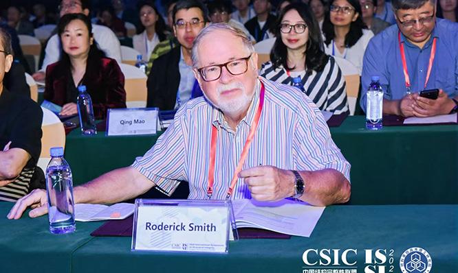
Finally, all at the EIS would like to pass on our sincere condolences to family, friends and colleagues of Professor Roderick Smith. He served as President of the EIS for over a decade, was a key figure in its formation in the 1980s, and will be missed by all those he inspired throughout his life and career.
Spencer Jeffs
Obituar y: Roderick Smith
President of the EIS
Professor Roderick A. Smith
FREng

It is with profound sadness that we announce the sudden passing of Professor Roderick Smith, President of the EIS, who died on 26 December 2024, his 77th birthday, in a tragic walking accident during a family holiday in the Lake District.
Rod was a pivotal figure in the formation of the EIS during the early 1980s, providing unwavering support that has been instrumental in the charity's continued success. He graciously served as President for over a decade, a role he fulfilled with dedication and enthusiasm. His contributions to the Society’s international fatigue conferences at Cambridge University were invaluable, and his valedictory keynote at the 2021 conference was one of the highlights of the meeting.
Beyond his professional achievements, Rod’s warmth and enthusiasm left a lasting impression on all who had the privilege of knowing him. He will be deeply missed by the EIS community and the broader engineering world.
Born in Greenfield, Saddleworth, Rod’s early love of the outdoors began during family holidays in the Lake District. He attended Hulme Grammar School in Oldham and began his engineering career as a student apprentice with the David Brown Corporation in Huddersfield. This led to an undergraduate degree at St
John’s College, Oxford. He later completed a PhD at the University of Cambridge in 1974 under the supervision of Professor Keith Miller.
Rod’s distinguished academic career included roles at Cambridge, Sheffield and Imperial College London, serving as head of department at both Sheffield and Imperial College. His expertise in fatigue failure of metals, particularly in the rail industry, was internationally recognised. He played a key role in the Hatfield Rail Crash Inquiry, applying his extensive knowledge to enhance safety standards.
He also served as President of the Institution of Mechanical Engineers, as a Chief Scientific Adviser to the Department of Transport and was a Director of the UK Forum for Engineering Structural Integrity (FESI). As a Trustee of the Science Museum, he was instrumental in securing the Japanese Bullet Train for the National Railway Museum in York, reflecting his dedication to preserving engineering heritage.


SEMINAR | Tyre Testing & Modelling: Accelerating the Future of Automotive Innovation – HORIBA
Rod’s love of the mountains was lifelong, surpassing even his passion for Manchester United Football Club. He climbed all the Lakeland Wainwrights and led expeditions to Greenland, Arctic Norway, the Himalayas and the Karakoram. A proud member of the Fell and Rock Club, the Alpine Club, the Arctic Club and the Yorkshire Ramblers’ Club, he undoubtedly had an adventurous spirit.
Rod is survived by his wife, Yayoi, and his loss is deeply felt by his extended family in the UK and Japan, as well as his countless friends and colleagues worldwide.
A memorial service will be held at 2pm on Friday, 7 March 2025, at the University Church of St Mary the Virgin, Oxford, OX1 4BJ. His colleagues and friends are invited to attend. The service will also be live-streamed, with a link available closer to the time on the tribute website (see below), or from the CS Boswell Funeral Directors.
As a tribute to Rod, donations can be made to the Langdale and Ambleside Mountain Rescue Team: Roderick Smith, 1947–2024.
Rod speaking at the Fatigue 2017 Conference Dinner.
Rod at Fatigue 2024.
Only in November, Rod attended and presented at the International Symposium on Structural Integrity (ISSI2024) in Dongguan, China.
The EIS Celebrates 40
Years in 2025

From the outset, the EIS has been dedicated to supporting engineers in industry and academia. We have always had a keen interest in engineers at the beginning of their careers and this commitment has taken many forms. Over the past four decades we have organised a huge variety of events, from exhibitions and conferences to seminars, webinars and specialist working groups. These activities have been at the heart of our technical themes of durability, fatigue, measurement and analysis, NVH, and sound and vibration. Most recently, we have expanded our student support through charitable donations and we are proud to announce our sponsorship of projects at the Universities of Glasgow, Sheffield and Leeds in 2025.
To mark our important anniversary year, the EIS has planned an exciting calendar of celebratory activities. Our annual Instrumentation, Analysis, and Testing Exhibition will see an expanded format, offering increased opportunities for both exhibitors and visitors. We are excited to launch the “40 for 40” initiative in May, where we will offer early-career engineers a unique forum for professional development and recognition.

The Engineering Integrity Society is delighted to announce Dr Niall Smyth as the new Chairperson of the Durability & Fatigue Group. Niall brings a wealth of experience and expertise to the role, with an impressive academic and professional background in the field of structural integrity.
Niall is currently a Research Fellow at Coventry University's Institute for Future Transport and Cities. He holds a PhD from Cranfield University and a bachelor's degree in Aeronautical Engineering from the University of Limerick, Ireland. His professional experience includes working as a Stress Engineer for Bombardier Aerospace, where he provided stress substantiation for the Global Express series of aircraft.
In addition to his industry and academic achievements, Niall is a member of the editorial board of the International

2025 marks a momentous milestone for the Engineering Integrity Society as we celebrate 40 years since our inception. Established in 1985 by a group of passionate young engineers under the leadership of Dr Peter Watson, the EIS was founded with a vision to share knowledge and drive advancements in mechanical engineering.
For young engineers, the prestigious Peter Watson Prize will once again provide an opportunity to showcase talent, with the final scheduled for October. Supporting the next generation of engineers remains central to our aims, and we are excited to see these initiatives unfold.
In September, we will publish a special edition of our journal, reflecting on the achievements of the past 40 years. This commemorative issue will celebrate the society's journey and the many individuals who have contributed to its success.
The year will conclude with our 40th Anniversary Dinner on 29 November at Nuthurst Country Lodge Hotel near Solihull. This special celebration will bring together longstanding members and more recent colleagues, offering an opportunity to reflect, celebrate, and look ahead to the future. As we embark on this celebratory year, we extend our gratitude to all our members, supporters and partner organisations who have been part of this incredible journey. Here’s to the next 40 years of engineering excellence and collaboration!
Engineering Integrity Society Welcomes
Niall Smyth as Chairperson of the Durability & Fatigue Group
Journal of Microstructure and Materials Properties. His research focuses on fatigue and fracture mechanics, finite element analysis, advanced materials and structural integrity.
We extend our sincere gratitude to Peter Bailey of Instron, who has served as Chairperson of the Durability & Fatigue Group for a number of years. Peter’s contributions have been invaluable, and we are pleased that he will continue to play a key role within the society as both a Director and member of Council.
We are excited to welcome Niall to the team and look forward to his contributions in advancing the group’s initiatives and goals.

Saturday 29 November 2025
Nuthurst Grange Country House Hotel, Solihull


For more information and to reserve your place visit: www.e-i-s.org.uk

This paper was reproduced from the EIS Fatigue 2024 Conference Proceedings.
Technical Paper:
Design, Usage And Safety Aspects For Tubular Specimens For Materials
Qualification With Pressurised Hydrogen
Ken Wackermann, Fabien Ebling, Thorsten Michler, Frank Schweizer and Heiner Oesterlin Fraunhofer Institute of Mechanics of Materials, Freiburg, Germany
Author correspondence: ken.wackermann@iwm.fraunhofer.de
Typically, autoclaves are used to characterise materials under a hydrogen atmosphere. Those systems are expensive in installation and usage due to high safety requirements. A cost-efficient and reliable alternative without the need for explosive protection might be the tubular specimen technique. In this technique, a small diameter axial hole is machined in the centre of the specimen, which is pressurised with gas. Comparing the results of specimens filled with pressurised hydrogen and, for reference, with ambient air or pressurised nitrogen allows us to conclude for the effect of hydrogen on material properties. The advantage of the tubular specimen technique is the very low volume of the explosive gas, compared to conventional autoclaves. This reduces safety risks and allows the implementation in existing testing machines with low efforts. This paper describes in detail the setup of a tubular specimen test system for tensile tests, addresses safety aspects and shows exemplary results.
Keywords:HydrogenEmbrittlement,TubularSpecimen, PressurisedHydrogen,MaterialsCharacterisation
INTRODUCTION
Nowadays, hydrogen is being considered as a possible storage and transportation solution for renewable energy from sources such as wind and solar power. Pressurised hydrogen can be used in various ways, such as in gas turbines to produce electricity, as a starting product in chemical plants, or in fuel cells to power ships and airplanes. To ensure the safe and reliable use of these products, material properties are needed for the design process. Materials qualification under pressurised hydrogen atmosphere is typically performed using autoclaves attached to conventional test rigs. The advantage of autoclaves is that tests, such as tensile
tests, fatigue tests, or fracture mechanics tests, can be conducted according to international ISO or ASTM standards [1, 2]. However, the drawback of autoclaves is that the pressure vessel is around the specimen, leading to high investment costs due the big size of the pressure vessel and for safety issues with explosion protection. Furthermore, certain temperature ranges above 300°C or below -100°C are very difficult or even impossible to achieve with autoclaves, although temperatures above 300°C are normal operating temperatures for internal combustion engines.
One alternative is the use of tubular specimens, which are tube-like specimens filled on the inside with pressurised hydrogen. The idea dates back to the 1970s and 1980s [3–5], and today, a standard for tensile testing of tubular specimens is being prepared by ISO/ TC 164/SC 1/WG 9. The obvious advantage of tubular specimens is the lower volume, which drastically reduces the amount of hydrogen to a few litres even at high pressures, reducing the risk of explosion. Furthermore, it is possible to use induction heating or a climate chamber for high or low temperatures. However, there are some drawbacks, such as specimen production and the question of how results achieved on tubular specimens compete with conventional specimens tested in an autoclave. This paper describes the setup of a tubular test system, compares the safety aspects to autoclaves, shows results for tensile tests, and addresses the current scientific questions regarding the use of tubular specimens for tensile tests.
TEST SETUP FOR TUBULAR SPECIMEN
Tubular specimens resemble conventional specimens, but with an axially centred longitudinal hole. In Figure 1 (upper) a picture and (lower) a technical drawing of a tubular tensile test specimen are shown.


There are some methods to develop the longitudinal hole. One of them is deep hole drilling. Special drills are used for this purpose, which have channels in the centre for lubricant transport through the drill to the cutting tip. This ensures good lubrication and cooling, and chips are transported away by the returning lubricant. Better lathes are required for this, with sufficient pumping power for lubricant transport. Normal lathes with pressure up to 40 bar are not sufficient, where better results are achieved by using at least 80 bar. Additionally, the lathes often have stabilisers for the drills to prevent the long drills from breaking. Although the surface quality of this method is better than that of ordinary drill presses, polished surfaces have a surface roughness that is approximately 10 times lower.
As an example, surface roughness measurements on the inner and outer surface of a tubular specimen made of Inconel 718 are shown in Table 1. The results comparing tubular specimens and conventional specimens, shown later in the document, indicate that the surface quality is acceptable for tensile testing. However, it is not under all circumstances sufficient for fatigue tests, for which normally polished surfaces are used. Therefore, methods to optimise the inner surface quality and understand its effect on fatigue tests remain a topic of research and engineering.
In the following, the setup is described. At both ends of the specimen, threads are present to attach the fixture plates, as depicted in Figure 2a. To enable a backlash-


free connection, a nut is used. On the very ends, a double ferrule connects the tubes and valves for the hydrogen supply, as shown in Figure 2b. This transportable system, comprising the specimen, fixture, and hydrogen connection, is taken to the gas station for hydrogen filling. This allows the hydrogen usage in a running test to be limited to a maximum pressure-volume product of less than 2 litres. After filling, the transportable system is mounted to the load rig, as shown in Figure 3a and 3b. On the outside of the fixture there are alignments fitting to the counterpart in the test rig to achieve a good alignment.
Since there is no hydrogen supply attached during a running test, leakage is critical for the success of the test. For this reason, membrane valves or needle valves with very low leakage are used. For slow strain tensile tests, running for about half a day, the pressure loss by leakage
is less than 1% of the starting pressure. In fatigue tests conducted over several days, the pressure loss is even lower.
The reason for the higher pressure loss in the tensile test is assumed to be the volume increase due to plastic deformation in a tensile test.
HEATING, COOLING
AND SAFETY ASPECTS
Autoclaves used for testing conventional, normal-sized specimens in fatigue or tensile tests under pressurised hydrogen typically have an inner gross volume of a few litres. The net volume can be reduced by filling bodies, but there is a practical lower limit of approximately 0.5 litre as space is required for measurement devices and movement of the fixture, specimen, and drive shaft. With an inner pressure of 200 bars, this results in a hydrogen

Outer surface after polishing
Table 1: Inner and outer roughness of a tubular specimens of Inconel 718.
Figure 2: a) Specimen connected to the movable fixture and the tubes of hydrogen supply. b) Whole set of movable parts.
Figure 1: Picture (upper) and technical drawing (lower) of a tubular specimen for tensile testing.

volume of 100 litres. Additionally, there is a permanent leakage at the gaskets sealing the drive shaft against the body of the autoclave. The explosive protection of the autoclave should therefore control both dangers of hydrogen release: (i) the permanent leakage and (ii) a possible fracturing gasket. In contrast, the tubular specimen has a pressure-volume product of less than 2 litres for pressures up to 400 bars and there is very little leakage. However, the gas is released at the end of the test by the fracture of the specimen, and the explosive protection needs to be adjusted to this danger. Normalsized laboratory rooms often have a minimum crosssection of at least 5 m by 5 m and a ceiling height of 2.4 m, resulting in a volume of 60,000 litres. The resulting mean hydrogen concentration in this size of a room at fracture is far below the lower explosive limit of about 4% of hydrogen in air. More critical is the short time concentration upon fracture, which will be close to the point of fracture in a range inside the explosive concentration. For the shown test system, the hydrogen concentration was, assuming that hydrogen moves upward as it is lighter as air, measured upon fracture at 0.5 m above the point of fracture and on the ceiling of laboratory room of earlier mentioned size. The measured hydrogen concentration of about 0.5% at the 0.5 m position is below the lower explosive limit. On the ceiling, the hydrogen concentration was in the ppm range. Five minutes after the fracture, no hydrogen was detectable in the room. Nevertheless, molecular hydrogen does not
react with the oxygen in air without the starting energy. As a result, hydrogen could accumulate over days. This can be prevented by a ventilation system. Still, tubular specimens generally have lower safety concerns for explosive protection, but national explosive protection requirements must be respected in any case. For the shown test system, beside the limitation for a maximum pressure-volume product of 2 litres, no further explosive protection was used.
Main advantages of tubular specimens in comparison to autoclaves are easier heating and cooling, compare Figure 4. In Figure 4a, the tubular specimen technique is shown in combination with an induction coil for temperatures up to 800 °C. The coil is open at the front to allow the installation of the hydrogen-filled specimen, including the hydrogen connectors. The temperature distribution is fine for the short measuring area of fatigue specimens but is insufficient for tensile tests, which is intrinsic for most induction heating systems. As tests end with a fracture, there is a risk of ignition of the escaping gas above the ignition temperature, resulting in a darting flame. For the shown setup, a darting flame was acceptable as there were no combustible parts close to the specimen, namely about 1 m in each direction, and the strictly limited hydrogen in the specimen. Risk assessment is always situation-dependent and must be individually conducted for each setup.


Figure 4b shows a liquid bath installed around the specimen. The hydrogen is contained within the specimen, and the liquid on the outside can be used for heating and cooling. In the depicted image, the bath was filled with liquid nitrogen for tensile and fatigue tests at 77 K. When this system is in use, a ventilation system and an oxygen gas alarm are employed in the laboratory for the safety of personnel due to the low oxygen concentration in the air caused by the evaporation of nitrogen.
Using a temperature chamber for the tubular specimens enables testing across a wide range of applicationrelevant temperatures, as demonstrated in Figure 4c. The temperature chamber depicted in the figure is equipped with a fan on the backside to circulate internal gas, a hole for injecting liquid nitrogen to achieve cooling, and electrical heating rods. The drive shaft of the fan is going through a very thin hole to prevent hot or cold gases coming from the chamber entering and damaging the power drive. At low temperatures conducted by injecting liquid nitrogen, explosive atmospheres are not a concern as there is already mainly inert nitrogen. Heating is more critical as the heating rods reach temperatures far above the ignition temperatures of hydrogen. As a solution, constant nitrogen flushing can be used to prevent explosive atmospheres. It helps that there is no constant hydrogen supply on the setup and the amount of hydrogen in the specimen is limited.
All three test systems have been or are currently being used on a daily basis for months without any safety concerns. The only exception is the setup with the temperature chamber, which is relatively new and has only been used for exemplar tests so far.
However, the shown risk assessment and explosive protection solutions are specific solutions for the three shown test systems and mentioned exemplarily. It is highly recommended to conduct a comprehensive risk analysis and develop an individual explosive protection solution in accordance with national safety and explosive protection regulations for each unique setup.
EXEMPLARY TENSILE TEST RESULTS ACHIEVED WITH TUBULAR SPECIMENS
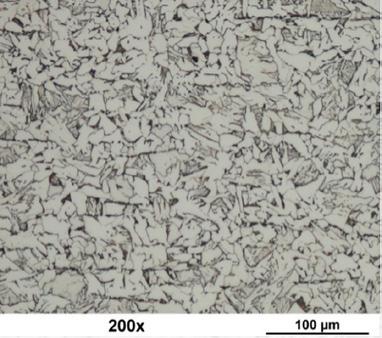
Tensile tests were conducted on specimens extracted from the used pipeline of the vintage ferritic steel StE360. The chemical composition is given in Table 2. StE360 is a plain carbon steel with slightly increased manganese content and a similar available material nowadays is the API 5L X52.
The steel has a typical ferritic-pearlitic microstructure with carbon bulk inclusions, as shown in Figure 5a. Slow strain tensile tests were conducted on tubular specimens filled with hydrogen 5.0 at 70 bar, as well as nitrogen for reference.
Hydrogen reduces the elongation of fracture (EF) but does not have an effect on the yield and tensile strength, as demonstrated in Figure 5b. The impact of hydrogen embrittlement becomes noticeable at high strains, which is observed in many steels with low and average tensile strength, compare also Figure 7. A better and more measurable parameter to assess the impact of hydrogen is the reduction of area (RA). In Figure 6 the fracture morphology in the scanning electron microscope (SEM) is shown.
The fracture surfaces of the reference specimens exhibit an obvious necking and a ductile cup-and-cone fracture. In contrast, the hydrogen-tested specimens display a brittle fracture surface and do not exhibit a distinct necking. Nevertheless, the fracture morphology is typical for hydrogen-induced fracture in these materials [6–9]. The textbook brittle fracture surface with clearly visible grain boundaries and secondary cracks is not observed in all materials and under all conditions.
When comparing the material properties obtained from tubular and conventional specimens, it becomes evident that both techniques offer specific advantages, as results on 26 bcc steels with ferrite-pearlite, pearlite, bainite, or martensitic microstructures show. No changes in yield strength and tensile strength due to hydrogen

Table 2: Chemical composition of steel StE360.
Figure 5: a) Light microscope picture of the microstructure of vintage pipeline steel StE360 and b) the stress-strain curve of tubular specimens of StE360 filled with pressurised hydrogen or nitrogen at 70 bars.
Figure 3: a) Test system with an installed tubular specimen. b) Magnification of the specimen installed to the test system.
Figure 4: a) Test system with a tubular specimen and induction heating for isothermal fatigue testing. b) Test system for tubular specimen and a liquid nitrogen cooling bath for tensile and fatigue tests at 77 K. c) Setup with a chamber for temperaturecontrolled isothermal tensile and fatigue tests between -80 °C and +200 °C.


are observed in both tubular and conventional specimens, compare Figure 7. However, the degree of necking is dependent on the specimen geometry and the test gas, compare Figure 8. In the reference atmosphere, conventional specimens exhibit greater necking than hydrogen-tested specimens. Conversely, for tubular specimens, those tested in hydrogen show more necking. This indicates that conventional specimens are more susceptible to hydrogen embrittlement, if the degree of necking is considered. Therefore, even minor changes in necking in tubular specimens may indicate hydrogen embrittlement. Comparable results with respect to tensile strength, yield strength, and necking behaviour are also published in [10] for austenitic steels 1.4301, 1.4305, 1.4306, 1.4404, 1.4408, and 1.4571. It is unknown whether this behaviour applies to high-strength steels, as no results on metallic materials

on tubular and conventional specimen tests with hydrogen or reference gas has not been done so far.
A proposed reason for the divergent susceptibility for hydrogen embrittlement of tubular and conventional specimen could be the different supply of hydrogen, compare Figure 9.
For conventional specimens the position of highest stress, crack initiation and hydrogen supply are the very same position. Therefore, damage by necking and damage by hydrogen are in competition. Multiple cracks initiate on the outside and once a leading crack arises, this grows, supported by hydrogen rather quickly, leading to an early fracture and reducing the possible necking, which is governed by plastic deformation. For tubular specimens, multiple cracks initiate on the inside, but necking still starts from the outside. Especially in the early stages, the crack growth does not benefit from the stress increase of the necking. Therefore, necking and crack propagation appear parallel, giving the necking more time before the final fracture appears.
SUMMARY AND CONCLUSION
The publication describes in detail the used setup for testing tubular specimen and addresses the safety aspects concerning explosive protection. The advantages of tubular specimens in comparison to autoclaves are the lower investment costs especially due to lower safety concerns. Results of tensile tests on tubular specimen filled with hydrogen and on conventional specimens tested in the autoclave are compared for metallic materials with ultimate tensile strength up 1500 MPa. For a wide variety of ferritic and austenitic steel, the yield strength and tensile strength are the same for conventional and tubular specimen. The results show that tubular specimens are a good alternative for tensile tests in the autoclave. However, the reduction of area of tubular specimens seems to be less sensitive for hydrogen embrittlement, which must be respected when interpreting the results.
ACKNOWLEDGEMENT
The financial support provided by the Bundesministerium für Wirtschaft und Klimaschutz and the Bundesministerium für Bildung und Forschung is gratefully acknowledged.
LIST OF SYMBOLS
CS Conventional Specimen
EF Elongation of Fracture
RA Reduction of Area
SEM Scanning Electron Microscope
TS Tubular Specimen
UTS Ultimate Tensile Strength YS Yield Strength
REFERENCES
[1] ASTM, Practice for Slow Strain Rate Testing to Evaluate the Susceptibility of Metallic Materials to Environmentally Assisted Cracking, G01 Committee, ASTM G 129, West Conshohocken, PA, 2021.
[2] SAEInternational , Standard for Fuel Systems in Fuel Cell and Other Hydrogen Vehicles, J2579_202301, 2023.
[3] Büchsenschütz, R., Beitrag zum Einfluß von Druckwasserstoff auf die mechanischen Eigenschaften von Stählen, Mat.-wiss. u. Werkstofftech. , Vol. 15, No. 5, 1984, pp. 186–189.
[4] Kaae, J., Final report on low-cycle fatigue and creep-fatigue testing of salt-filled alloy 800 specimens, 1982.
[5] Hydrogen Embrittlement Testing, ASTM Special TechnicalPublication543 , Philadelphia, 1972, 273 pp.
[6] Shen, S., Song, X., Li, Q., Li, X., Zhu, R., and Yang, G., Effect of CrxCy–NiCr coating on the hydrogen embrittlement of 17-4 PH stainless steel using the smooth bar tensile test, JMaterSci , Vol. 54, No. 9, 2019, pp. 7356–7368.
[7] Michler, T., Bruder, E., and Lindner, S., Hydrogen effects in X30MnCrN16‐14 austenitic steel, Materialwissenschaft Werkst, Vol. 51, No. 4, 2020, pp. 531–538.
[8] García, T. E., Rodríguez, C., Belzunce, F. J., and Cuesta, I. I., Effect of hydrogen embrittlement on the tensile properties of CrMoV steels by means of the small punch test, Materials Science and Engineering:A , Vol. 664, 2016, pp. 165–176.
[9] Ebling, F., Klitschke, S., Wackermann, K., and Preußner, J., The Effect of Hydrogen on Failure of Complex Phase Steel under Different Multiaxial Stress States, Metals , Vol. 12, No. 10, 2022, p. 1705.
[10] Michler, T., Freitas, T., Oesterlin, H., Fischer, C., Wackermann, K., and Ebling, F., Tensile testing in high pressure gaseous hydrogen using conventional and tubular specimens: Austenitic stainless steels, InternationalJournalofHydrogen Energy , Vol. 48, No. 65, 2023, pp. 25609–25618.
Figure 9: Schematic illustration of the proposed mechanisms of hydrogen damage in tensile test on (left) conventional specimen and (right) tubular specimen [10].
with tensile strengths above 1200 MPa are currently available to compare tubular and conventional specimen. Unfortunately, a systematic analysis of the elongation of fracture
Figure 8: Comparison of the reduction of area (RA) of conventional specimens (CS) and tubular specimens (TS) in tensile tests. Red dot = Test with hydrogen. Black dot = Reference test with pressurised nitrogen or with air.
Figure 6: Scanning electron microscope pictures of the full fracture surface for (a) the reference specimen tested with nitrogen and (b) the specimen tested with hydrogen. Magnifications of the fracture morphology seen in the scanning electron microscope for (c) the reference specimen tested with nitrogen and (d) the specimen tested with hydrogen.
Figure 7: Comparison of the (a) yield strength (YS) and (b) ultimate tensile strength (UTS) of tubular specimens (TS) and conventional specimens (CS) for all 26 tested materials. Red dot = Test with hydrogen. Black dot = Reference test with pressurised nitrogen or with air.
Industry News
University of Bristol celebrates double win at inaugural AI Award Ceremony
The University of Bristol has been crowned ‘AI University of The Year’ at the National AI Awards, solidifying the University’s reputation as a leader in artificial intelligence research and education. The University of Bristol initiative REASON Open Networks Project bagged the AI Award for High Tech & Telecom, rounding off a successful night for colleagues in the Faculty of Science and Engineering. From AI supercomputing to driving AI innovation within the telecom industry, responsible AI systems and interdisciplinary collaboration, the University’s contributions aim to set global benchmarks for academic institutions and business. For over two decades, Bristol has remained at the forefront of AI advancements, consistently driving forward solutions that address pressing challenges in fields as diverse as climate research, robotics, and healthcare. From the creation of autonomous robots in the 1940s and one of the first MSc programs in machine learning in 1998, the University continues to shape the University’s leadership in AI research, most evident by the recent launch of supercomputer Isambard AI, backed by a £225m investment from the UK government.
www.bristol.ac.uk
Unlocking Materials 4.0
A rise in Industry 4.0 technologies emphasises instantaneous data access for better-informed decisionmaking. While this is most common in manufacturing, many other "point four" paradigms are embracing the need for always-on, data-driven results. Materials 4.0 represents the convergence of advanced digital technologies with traditional materials science.

Inspired by Industry 4.0 principles, this approach leverages big data, high-throughput experimentation and integrated computational tools to reimagine material design and use. While this sounds promising, bringing Materials 4.0 for microscopy to fruition could be difficult and expensive. It often requires labs to have additional IT infrastructure that is capable of extracting value from the data generated by modern electron microscopes. Additionally, staff may require extensive training on new tools, and scaling these technologies across different departments can be challenging. Therefore, a microscopy system that’s ready for Materials 4.0 must be able to integrate into existing setups with ease and streamline data management.
Scanning electron microscopy (SEM) is a vital technology for data-driven material characterisation and analysis. The
high-resolution data generated by SEM can be integrated with machine-learning algorithms to automate complex microstructural analysis, identify defects and predict material properties. This approach enhances the efficiency of the materials discovery process, allowing for the rapid screening and optimisation of new materials. Today’s SEMs are a world apart from those used almost 100 years ago. Technologies such as Electron Backscatter Diffraction (EBSD) make it possible to analyse the crystallographic orientation and phase distribution of materials at the microstructural level. This high-resolution, quantitative data is crucial in the context of Materials 4.0.
Thermo Fisher Scientific’s ChemiSEM technology combines traditional SEM imaging with real-time elemental analysis, providing chemical composition directly within the SEM image. This integration enhances productivity and reduces sample analysis complexity. As data-driven decision-making rises across industry, materials analysis faces its own change precipice. While laboratory automation typically required an equipment overhaul and specialised expertise, access to integrable, user-friendly analytics is enabling a sectoral shift. Electron microscopy will remain fundamental in the characterisation and analysis of materials and, when enabled with the latest SEM technology, we’ll see Materials 4.0 truly come to fruition.
www.thermofisher.com
Transplantable piezoelectric biomaterial offers new treatment potential for central nervous system injuries and neurodegenerative diseases
A UK research team has created a new material for treating central nervous system injuries and neurodegenerative diseases, offering hope of new therapies to regain lost motor, sensory or cognitive functions. Researchers at the University of Bath and Keele University have invented a new composite material that can help neural stem cells to grow. The material has potential for use in new treatments for central nervous system injuries and neurodegenerative diseases.
Made from cellulose and piezo-ceramic particles, the composite is sustainable and has a range of properties that mean it can help to repair brain and spinal cord trauma. As well as traumatic injuries, the material could be used to treat diseases including Alzheimer’s and Parkinson’s Disease. A new electrically active transplantable material that can help to regrow cells in the brain and spinal cord could redefine the recovery prospects of patients who sustain life-altering injuries or suffer from neurodegenerative diseases. The 3D piezoelectric cellulose composite, invented by experts at the University of Bath and Keele University and detailed in a research paper published today, can be used as a bespoke "scaffold" into which neural stem cells (NSCs) can be precision-delivered to injury sites, helping to effectively repair and regenerate neurons and associated tissues crucial for recovery.
www.bath.ac.uk
www.keele.ac.uk
Lockheed Martin awards Alva Industries $1.85 Million contract to collaborate on advanced technologies and capabilities
Alva Industries (Alva), a manufacturer of frameless motors and owner and creator of FiberPrinting™ technology, announced it has signed a $1,850,000 contract with Lockheed Martin, a global defence technology company driving innovation and advanced scientific discovery, to develop new technologies in the aviation and defense industry. The partnership will leverage Alva’s deep expertise in motors and electric propulsion to develop specialised capabilities for small Unmanned Aerial Vehicles (sUAV). The technologies will improve UAV flight performance by enabling optimising properties that the end-user can interchange for different missions, such as maximising system efficiency for improved endurance, or noise reduction for operations where discretion is the priority. The initial project will last for 24 months with potential for continued collaboration on future initiatives, promoting the strong alliance between the US and Norwegian defence industries.
www.alvaindustries.com
Solar-powered aircraft achieves new stratospheric success
A British-led team of engineers has taken a leap forward in the race to harness the stratosphere for earth observation and communications, completing a new series of test flights of BAE Systems’ High Altitude Pseudo Satellite (HAPS) Uncrewed Aerial System (UAS), PHASA-35, in quick succession. During the first flight at Spaceport America in New Mexico, US, in recent weeks, the solarpowered aircraft flew for 24 hours climbing to more than 66,000 feet and cruising in the stratosphere, before successfully landing in a serviceable condition, meaning it was ready to fly again just two days later. This is a major milestone in the development of PHASA-35, named after its 35-metre wingspan, demonstrating its ability to be launched, flown, landed, potentially reconfigured and then relaunched again so quickly. Designed by BAE Systems’ subsidiary Prismatic Ltd to operate above the weather and conventional air traffic, PHASA-35, has the potential to provide a persistent and stable platform for uses including ultra-long endurance intelligence, surveillance and reconnaissance.
www.baesystems.com
Ansible Motion’s state-of-the-art simulation centre to be the first facility at Snetterton Innovation Park
Ansible Motion is set to become the first tenant at MotorSport Vision’s new Innovation Park in Snetterton, Norfolk, as it brings its global advanced driving simulator technology business to the site. Trusted by leading automotive manufacturers, top motorsports teams and cutting-edge research organisations around the world, the move to Innovation Park – adjacent to Snetterton Circuit in Norfolk, UK – sees Ansible Motion doubling the size of its facility from its existing base in Hethel, where it has been located since 2009. This additional footprint will enable Ansible Motion, a leader in Driver-in-theLoop (DIL) simulation environments which counts Ford, Honda, BMW Group, General Motors and Continental among its clients, to further expand its global operations.
MotorSport Vision – Europe’s largest motor racing circuit operator, which owns Snetterton Circuit – has plans for 30,000 sqm of commercial offices, industrial units and motorsport workshop space at the park. The 13-hectare
site will also feature a hotel with a café and electric vehicle (EV) charging facilities.
www.ansiblemotion.com
Biomedical professor leading non-contact radar sensors for better healthcare awarded top international engineering research prize
Dr Changzhi Li, a professor at Texas Tech University in the Department of Electrical & Computer Engineering, is pioneering the next generation of low-cost smart radar sensors for non-contact healthcare, advanced human–computer interaction and security surveillance. He has been awarded the Institution of Engineering and Technology’s (IET) prestigious £350,000 A. F. Harvey Engineering Research Prize. His portable radar sensors enable the monitoring of individuals without on-body devices, remotely checking small motions such as respiration and heartbeat. Li’s innovations have provided greater clarity on medical conditions like sleep apnoea and sudden infant death syndrome (SIDS) – and can also be seen in the touch-free gesture controls found in today’s electronics. Li’s work has also enhanced wireless human–machine interfaces and benefitted smart living and environmental monitoring – to provide accurate indoor user information and support next-generation energy efficiency and management. He holds 14 US patents with three others pending.
www.theiet.org
With Outsight and Hesai, embotech deploys new automated vehicle marshalling (AVM) capabilities in BMW’s european plants
Embotech AG, a provider of cutting-edge autonomous driving solutions for logistics, announces a strategic collaboration with Outsight, a leader in LiDAR software solutions and Hesai, a leading LiDAR hardware manufacturer, to deliver cutting-edge LiDAR technology and perception software for Embotech’s AVM technology deployed in BMW facilities and known internally at BMW as Automated Driving In-Plant (AFW). Within this AVN solution, Outsight plays a key role with its advanced LiDAR software platform that tracks the vehicle and the surrounding obstacles within BMW's production facilities, while Hesai supplies its industry-leading LiDAR sensors, renowned for their accuracy and reliability, which act as the "eyes" of the AVM system.
Initially implemented for the BMW 5 Series and 7 Series in Dingolfing, is now also in use for the MINI Countryman and other BMW models manufactured in Leipzig. Using this new setup developed by industry leaders in autonomous driving solutions and sensing technology, new vehicles drive fully autonomously along a route of more than 1 km, from the two assembly halls, through the “short test course”, to the plant’s finishing area. At the Dingolfing plant, while the vehicles drive themselves to the finishing area, the factory establishes a secure connection to the vehicles, controlling their movement through the quality assurance test drive. The integrated solution is now actively supporting the marshalling of newly manufactured vehicles through various stages of the production and logistics process in three BMW facilities, marking the initial phase in a global rollout to multiple plants across Europe and North America. www.outsight.ai
Contributions to Industry News may be emailed to managingeditor@e-i-s.org.uk. The nominal limit for entry is 250 words.
The Engineering Integrity Society is delighted to sponsor several university teams in their projects for 2025, including the Rail Challenge at Sheffield University (RCAS), University of Glasgow Racing, and Leeds University Rocket Association (LURA). Supporting early-career engineers is a key goal of the EIS, and we are proud to contribute to these innovative initiatives. We look forward to following the teams' progress throughout the year and celebrating their achievements.

Railway Challenge at Sheffield
Sponsored by the EIS
Research into Competition Car Aerodynamics

Railway Challenge at Sheffield (RCAS) is an extracurricular activity for undergraduate students and is the University of Sheffield’s entry into the IMechE Railway Challenge competition, held annually in June at Stapleford Miniature Railway in Leicestershire.
The team is currently composed of around 35 engineers from across the Faculty of Engineering, including; Mechanical, Automatic Control and Systems, Aerospace, General, Civil, Electrical, and Computer Science Engineering. Supporting the team are four PhD students from the School of Mechanical, Aerospace and Civil (MAC) Engineering. An academic supervisor, Professor Roger Lewis, also provides additional support.
The competition requires teams of students and recent graduates from across the globe to design and manufacture a 10¼” gauge locomotive to compete in a wide variety of dynamic, on-track challenges intended to replicate real challenges faced in the rail industry. The teams also compete in paperwork challenges designed to reflect the demands placed on an engineering team in industry. This year marks the team’s eleventh year involved in the competition and will be our tenth competing locomotive.
The team has always had a strong track record of results but were finally crowned Grand Champions in 2024, as well as winning several individual challenges. Due to the success of the tenth anniversary locomotive, the team has elected to retain it in full competition specification to train new team members, support the University, and exhibit at STEM outreach and other participation events. This means that a higher proportion than normal of limited financial resources will go toward a new vehicle.
The EIS has generously agreed to sponsor the team for this upcoming competition year to help enable the ambition for the 2025 locomotive to be the most radical in the team’s history, whilst retaining the success of its predecessors. Principally this support will help drive a change to the locomotive’s powertrain. The team’s basic powertrain design and philosophy has not changed since 2014, albeit with several successful iterations. In brief, this comprises a brushed DC motor driving two wheelsets through an intermediate shaft either using chains or belts. Relatively simple motor controllers are used to control this system. Although this system works, it is now very conventional.
The concept also has significant limitations with respect to the speed, safety, and ease of wheelset removal, which negatively affects performance in the ‘Maintainability Challenge’. An alternative system has been developed, which includes major mechanical changes to incorporate direct drive gearing and new electromechanical brakes to simplify wheelset removal. Implementation of a new powertrain design concept also allows the incorporation of new motors with more sophisticated motor controllers. This alteration delivers a step change in locomotive performance which should provide a more capable and reliable vehicle. An overview of the new system is shown on the opposite page.
Through participation in the Railway Challenge competition, the team now has a network of over 100 practising engineers in sectors including rail, automotive, energy, aerospace and academia. Individual testimony has highlighted that RCAS, and ultimately the Railway


Challenge competition, has been instrumental in many alumni securing their current roles.
RCAS also has an extremely high rate of members who join ‘Year In Industry’ and ‘Summer Placement’ programmes in a multitude of sectors; 2023 saw a 100% success rate.
These statistics serve to highlight how well RCAS has taken on the goal of ‘allowing aspiring engineers to build and showcase their skills, expertise, knowledge, and business acumen’ which is core to the Railway Challenge. The delivery of this mission will only be enhanced through the generous sponsorship from EIS for 2025.
RCAS is a diverse, talented and motivated group of young engineers who also regularly feature on mainstream, print, digital and video news extolling the virtues of not only taking part in the Railway Challenge, but also pursuing a career in Engineering to make a positive impact on the world.
The team looks forward to updating EIS members on how this year’s competition plays out, and progress can be followed across our social media pages (LinkedIn, Facebook, Instagram; @RailwayChallengeAtSheffield).

Dan Copson, Aerospace Engineering Student
Leeds University Rocketry Association
Sponsored by the EIS

Leeds University Rocketry Association (LURA) are a small but dedicated group of students trying to innovate in student amateur rocketry. Our long-term ambition as a society is to launch a rocket to the Kármán line, the internationally recognised boundary of space at an altitude of 100 kilometres.
LURA began by developing solid-fuel rockets, such as the Gryphon I, which placed 4th in its category at the illustrious Spaceport America Cup in 2022. However, in order to increase the performance of our rockets, we have also started developing our own liquid-fuel engines, and in 2023 we won the 2nd place Team Spirit award at the Race 2 Space National Propulsion Competition.


Whilst this victory was a big step forward, a complete rocket requires a feed system to supply the engine with fuel and oxidiser for combustion. Therefore, work began on Zola, a student-designed electric pump that will feed isopropyl alcohol (IPA) and liquid oxygen (LOX) into our engines at a pressure of 40 bar and a flow rate of 2.3 kg/s.
The design of the Zola pump is rather unique in rocketry applications; an electrically powered centrifugal pump in a canned motor design. Conventional electric pumps are driven by an external electric motor, whereas in
canned motor pumps, the impeller is integrated directly into the motor’s rotor.
This design has some big advantages. For example, a very compact pump can be achieved, and the liquid oxygen is able to circulate between the rotor and stator of the motor to provide cooling.
However, the unique design also presents unique challenges. After manufacturing and water testing a first prototype, we discovered that the additive manufacturing process used to make the rotor had left supports in the inducer that could not be removed. Additionally, the pump was in danger of cavitation, where fluid vaporises and recondenses to create damaging shockwaves.
Thanks to the generous sponsorship of the EIS, we are now able to build upon our first design and manufacture an improved prototype that addresses these challenges. It also will allow us to shift our focus from fixing critical issues to improving reliability, such as by appropriately balancing the rotor to ensure that the pump is capable of operating at its design speed of 50,000 RPM.

We are currently working with the University of Leeds to implement a testing campaign, which involves liquid nitrogen immersion and flow testing to ensure that the pump maintains structural integrity and performance when exposed to cryogenic temperatures.
Our aim for 2025 is to refine the design and win the ‘Best Pump’ category at this year’s Race 2 Space competition. In future years, the pump can then be tested in conjunction with our engines and will bring us one step closer to our dream of reaching the
line.

University of Glasgow Racing
Sponsored by the EIS
Driven by Passion, Powered by Innovation
At University of Glasgow Racing (UGRacing), we’re a team of students brought together by a shared passion for engineering, motorsport and innovation.
Competing annually in Formula Student UK, the world’s most prestigious student motorsport competition, we aim to push the boundaries of what’s possible while gaining invaluable real-world experience.
From IC to EV: Embracing the Future
UGRacing has a proud history of success. Since our founding in 2014, we’ve grown into one of the UK’s most competitive Formula Student teams. In 2022, we celebrated a milestone by winning the Formula Student competition with our last internal combustion (IC) vehicle. This made us only the third UK team to ever win. That victory marked the perfect conclusion to our IC journey, as we decided to shift our focus entirely to electric vehicles (EVs), embracing the challenge of sustainable technology and the future of motorsport.
This year, we’ll be unveiling our third EV at Formula Student UK 2025 (FSUK25). Building on last year’s strong showing – including a win in the static events – we’re determined to take things further by producing a car that excels on track. With a renewed focus on dynamic performance and reliability, this season represents another exciting chapter in UGRacing’s journey.
Our Focus for FSUK25
For the 2025 season, our aim is to enhance the car’s dynamic performance. By adopting a vehicle dynamicsdriven design approach, we’re optimising handling, acceleration and overall stability. A key milestone for us this year will be on-track testing. This allows us to gather essential data from a host of new sensors, identify areas for improvement, and ensure that the car performs as expected under competition conditions.
Overcoming Challenges
Every season comes with its challenges and FSUK25 is no exception. Transitioning to electric vehicles has been a steep learning curve for the team, with new systems like battery design, thermal management and software integration presenting complex technical problems to solve. With around 150 members from diverse disciplines, coordinating efforts and maintaining effective communication is no small task. Balancing academic work, personal commitments and the demands of building a high-performance race car adds to the challenge. But our shared passion for motorsport and teamwork keeps us focused on the finish line.
How Sponsorship Powers Us
Sponsorship plays a vital role in UGRacing’s success. Support from organizations like the EIS directly funds the critical components and materials we need to
manufacture our car, including advanced battery systems, precision-machined parts and testing equipment. Their financial backing ensures we can source high-quality materials and cover essential production costs, enabling us to build a car that meets the rigorous demands and safety standards of competition. With their help, we can also carry out the extensive testing required to optimise performance and ensure our car is race-ready.
Our Team and Values
UGRacing is more than just a team – it’s a community. Students from engineering, business and design backgrounds come together, contributing their unique skills to achieve a shared goal. From technical design to managing sponsorships and logistics, every member plays an essential role in our success.
Central to our ethos is the unofficial motto, “Built Not Bought.” This philosophy encourages members to design, build and understand every system in the car from the ground up, rather than relying on off-theshelf solutions. It’s a hands-on approach that fosters innovation, develops practical skills, and sets us apart in the competition. We’re also passionate about inspiring others. Through outreach programs and public events, we aim to share our love for STEM and motorsport, encouraging others to pursue their own ambitions.
Looking Ahead
With the bulk of our design process complete, we’re entering the manufacturing stage of the UGRacing season. This is where the hard work and planning from months of design come to life, as we assemble and refine our car for testing and competition. The EIS’s financial support is critical during this phase, enabling us to source precision parts and custom components while ensuring the car is ready to perform at its best on track.
As FSUK25 approaches, we’re excited to see our efforts come to fruition. Every step of this journey reflects the dedication of the UGRacing community and the generosity of our sponsors.
Thank You to Our Supporters
UGRacing’s journey wouldn’t be possible without the incredible support we receive. From the University of Glasgow to our sponsors, alumni network and industry partners like the EIS, every contribution helps us chase our dreams. As FSUK25 draws closer, we’re ready to take on the challenge with determination and optimism. Stay tuned as we continue to push the limits of engineering and make history once again.
Kármán
Zola: Fuelling New Heights in Student Rocketry
Written by Samuel Krain, MEng Embedded Systems Engineering (Zola Team Lead)
Zola team: Samuel Krain, Raul Galindo Salazar, Gregory Cramb Previous members: Joseph Humphreys, Dominykas Buta, Toby Thomson
Figure 2: Exploded view of the first Zola pump prototype.
Figure 1: Our ‘Louie’ engine during a test fire at Race 2 Space in 2023.
Figure 3: First rotor prototype for Zola.
News from British Standards


News from MIRA Technology Institute
We begin the new year here at BSI (the British Standards Institution) with great news from one of our remanufacturing standards groups.
The group is responsible for the BS 8887 series of TPR/1/7/4, the group of UK lighting remanufacturers who came together a few years ago to discuss and agree on best practice for their sector, have now delivered a brand-new standard – a new part of the BS 8887 series: BS 8887-221:2024, Design for Manufacture, Assembly, Disassembly, and End-of-Life Processing – Part 221: Remanufacture of luminaires. Code of Practice. The document was published just before the end of 2024 –an exciting and early Christmas present!
The new standard is available to purchase from BSI’s website and online shop (https://knowledge.bsigroup. com/). BS 8887-221:2024 aims to provide clear guidance for manufacturers and customers on extending the lifecycle of luminaires and lighting equipment to reduce waste, conserve resources and advance the circular economy. The guidance is designed to help the lighting industry enhance its sustainability by lowering demand for virgin materials, reducing energy consumption and minimising use of resources in production.
Throughout the development of BS 8887-221:2024, BSI brought together relevant stakeholders from across the lighting industry, including leading UK lighting remanufacturers and industry bodies, lighting industry associations, plus relevant academic institutions and research bodies. It has convened the meetings necessary to enable key UK experts to determine and shape best practice for the industry’s specific needs/requirements in remanufacturing. The rest of the TPR/1 – Technical Product Realization – standards area also had a very busy 2024. Work to revise BS 8888, the UK’s national framework standard for technical product specification and documentation, was ongoing throughout the year with publication expected midway through 2025.
BS 8888 is the successor to the UK’s much-loved engineering drawing standard BS 308 – first published in 1927 and the world’s first engineering drawing standard. BS 8888 first came out in 2000, when BS 308 was withdrawn, and the 2025 edition will be 10th version of this indispensable tool for engineering designers. In terms of other national standards activities, our committees are now planning and preparing for another busy year ahead of meetings, project work, events and launches.
First up in March is the hosting of one of the key international committees in the engineering design and specification area. ISO/TC 213, the international committee responsible for geometrical product specification and verification standards, is coming to London for two weeks of meetings at BSI’s offices in West London starting on Monday 3rd March.
With all of the ongoing work and activity in the TPR/1area committees, we are always looking for new committee members and experts to join our standards drafting groups, national committees, and international working groups. Further general information on taking part in BSI’s standards work can be found at: https://www.bsigroup.com/en-GB/about-bsi/uknational-standards-body/how-to-get-involved-withstandards/
And if you would like further information on any of TPR/1’s projects or work programme – or if you would like to get involved in any way in the committee’s standards development activities – please contact Sarah Kelly, Lead Standards Development Manager and Committee Manager for TPR/1, at BSI on sarah.kelly@bsigroup.com.


Bridging the Skills Gap: Industry and Education Unite
In the rapidly evolving landscape of technology, the need for a skilled workforce has never been more critical.
The MIRA Technology Institute (MTI) is at the forefront of this movement, working tirelessly to bridge the skills gap in the automotive industry. Craig Line, Emerging Technology Delivery Manager at MTI, is leading the charge to ensure that businesses are prepared for the future.
Craig's extensive background as a heavy vehicle and bus and coach technician has given him unique insights into the industry's needs. He notes that the traditional roles of electricians and mechanics are merging into a new hybrid role known as 'MechElec.' This role requires a blend of mechanical and electrical skills, essential for diagnosing and repairing modern electric vehicles (EVs).
The transition to electrification demands a workforce capable of handling complex electrical energy storage and propulsion systems. Craig emphasises the urgency for employers to upskill their workforce to keep pace with technological advancements. Without swift action, companies may struggle to maintain their fleets and infrastructure as they transition to EVs.
MTI has been proactive in addressing this challenge by partnering with major original equipment manufacturers (OEMs) like Jaguar Land Rover and Bentley. These collaborations aim to upskill their workforce through bespoke training packages. The MTI's state-of-the-art facilities at the MIRA Technology Park provide an ideal environment for this training.
recently developed hydrogen training panel allowing students to safety de-gas, remove, preplace and regas hydrogen systems. This practical experience is crucial for developing the skills needed to work with hydrogen-powered vehicles.
The MTI's commitment to education extends beyond current industry professionals. They are actively engaging with the future workforce by inspiring young people to pursue STEM careers. The institute offers work experience packages and taster events for schools, including the HG2P Sprint launch bundle, which allows students to build and race their own mini hydrogen vehicles.
The MTI's Skills Escalator is a unique initiative that enables students to progress through various levels of training within the same institution. Since its inception, the MTI has welcomed over 60,000 students and delegates, offering accredited qualifications from Level 1 certificates to Master's degrees. This comprehensive approach ensures that individuals can continuously develop their skills and advance their careers.
In conclusion, the collaboration between industry and education is vital for addressing the skills gap in the automotive sector. The MTI's efforts to provide cuttingedge training and foster a future-ready workforce are essential for the industry's transition to electrification and beyond. By working together, industry and education can ensure that the workforce is equipped with the skills needed to thrive in a rapidly changing technological landscape.


Government funding through the Local Skills Improvement Fund has enabled MTI to invest in cutting-edge equipment. This includes a hydrogen training rig from Block Automotive and Electric Vehicle Systems Panel Trainers from LJ Create. These tools allow students to gain hands-on experience with the latest technologies, preparing them for the future of the automotive industry. Hydrogen fuel is gaining momentum as a viable alternative to traditional fuels, supported by the government's Hydrogen Net Zero Investment Roadmap.
The MTI's hydrogen training rig, featuring a cutaway section of a Toyota Mirai, allows students to practice diagnostic skills on pre-installed faults. Along with our
Lisa Bingley Operations Director MIRA Technology Institute (MTI)
EIS Launches
'40 for 40' to Celebrate 40th Anniversary

The EIS is set to mark its 40th anniversary in 2025 with an exciting new initiative: '40 for 40'. Designed to support and inspire early-career engineers, this year-long programme aims to identify and nurture up to 40 participants through a bespoke series of events, workshops and networking opportunities.
What's Involved?
The '40 for 40' programme will feature quarterly one-day events hosted at various locations across the Midlands. Each event will include engaging seminar presentations from industry experts, interactive workshops and invaluable networking opportunities. The first event is scheduled to take place in May 2025, with participants expected to attend one event per quarter to fully benefit from the programme.
Benefits
Those taking part in the '40 for 40' initiative will benefit from:
• Gaining knowledge and hands-on experience.
• Exposure to a wide range of engineering topics.
• Developing technical, leadership and collaborative skills.
• Building a strong professional network.
• Direct access to industry experts.
• Opportunities to gain competency skills (C, D & E) required for Chartered Engineer status.
Who Can Apply?
The programme is open to engineering students, PhD researchers and engineers with up to six years of professional experience.
How to Apply
Interested candidates can apply by completing the online application form.
Application Deadline
The deadline for applications is 31 March 2025.
The '40 for 40' programme promises to be a unique opportunity, equipping the next generation of engineers with the skills, knowledge and connections needed to excel in their careers. Don't miss out on the chance to be part of this unique and exciting opportunity.
ENGINEERING INTEGRITY SOCIETY

A year-long programme, ‘40 for 40’ celebrates the EIS’ 40th anniversary in 2025. This initiative will identify and support up to 40 early-career engineers through a bespoke programme featuring seminars, workshops and networking opportunities.


News from the Women's Engineering Society
Throughout 2024, the Women’s Engineering Society (WES) proudly celebrated and recognised exceptional talent and contributions to engineering through our annual awards program. These awards allow us to highlight those driving innovation and advocating for diversity within the engineering sector.
In December 2024, we hosted our annual Caroline Haslett Lecture at the Geological Society in London, where we announced the winners of our prestigious awards for the year. The Karen Burt Memorial Award is for the best newly qualified chartered engineer and was awarded to Kerry Evans.
The Amy Johnson Inspiration Award, was launched in 2016 and we present to individuals who are not currently working as an engineer or within the applied sciences who have made a profound impact on advancing women in engineering. For 2024 this was awarded to Laura Hughes from Amazon for her work in inspiring and supporting the next generation of female engineers.
The Men As Allies Award seeks to celebrate a male working within the engineering, technical and applied sciences sectors who has gone above and beyond the call of duty to support his female colleagues and address the gender imbalance within engineering. We were

delighted to award this to WES Trustee Vince Pizzoni. For 2024 we also had two new awards, the Newly Incorporated Engineer Award presented to Lucy Davies and the Newly Registered Technician Award which was won by Isobel Howe.
As well as the WES awards our Top 50 Women in Engineering (WE50) initiative remains a flagship program, showcasing the diverse roles women play in engineering and technology. For 2024, the WE50 list focused on women who were making innovations within engineering under the theme Enhanced By Engineering.
For us, these awards go beyond recognition – they serve as a platform to raise awareness of the systemic challenges women face in engineering. They highlight role models whose stories inspire others to pursue and persevere in engineering careers. By showcasing these success stories, we reinforce our mission to create a more inclusive and equitable industry. Our awards also provide recipients with a platform to amplify their work and advocacy, often leading to further opportunities to drive change.
As we continue into 2025, we are excited about the upcoming International Women in Engineering Day (INWED), on 23 June each year. For 2025 the theme, “Together We Engineer”, emphasises collaboration and collective efforts to innovate, solve global challenges, and make engineering more inclusive.
Aligned with the spirit of our awards, INWED 2025 will celebrate teamwork across disciplines and industries, highlighting the power of diverse voices working together. The event will include campaigns, webinars and public engagements, amplifying the importance of unity in achieving engineering excellence.
By celebrating individual and organizational achievements, we inspire the broader industry to strive for greater inclusivity and innovation. As we look forward to INWED 2025 and its collaborative theme, we are reminded that together we engineer a brighter, more equitable future.
Candi Colbourn Events and Marketing Manager www.wes.org.uk
Instrumentation, Analysis and Testing Exhibition 2025
29 April 2025, Silverstone Race Circuit
As the Engineering Integrity Society marks its 40th anniversary in 2025, we reflect on four decades of bringing together engineers from industry and academia to exchange ideas, knowledge and experience. To celebrate this milestone, the society is hosting the all-new Instrumentation, Analysis and Testing Exhibition on 29 April 2025 at the iconic Silverstone Race Circuit.
This year’s exhibition is set to be the largest in the Society’s history, with over 80 exhibitors representing key sectors such as automotive, aerospace, off-highway, motorsport and medical testing. Free to attend, the event has grown significantly over the past decade and this year has expanded to two larger halls to accommodate the increasing demand from exhibitors and visitors alike.

Dr. John Yates, Chairman of the EIS, shared his thoughts on the event:
“The Instrumentation, Analysis and Testing Exhibition is much more than just a trade show; it’s a unique event specifically focusing on the test and measurement industries. It provides an unrivalled opportunity for professionals across industries to come together, exchange ideas, and discover the latest advancements in testing and measurement technologies. This year’s event, coinciding with our 40th anniversary, promises to be particularly special, offering something for everyone – from established experts to young engineers just starting their careers.”
The following exhibitors will be present this year:
1g Dynamics Limited
Acoustic Camera UK Ltd
Aerotech Inc
Aircraft Research Association Ltd
AML Instruments
Applied Measurements Ltd
AVL UK Ltd
Axiometrix Solutions
Beamex Ltd
b-plus technologies GmbH
Centrateq Ltd
CoMech Metrology Ltd
Concorde Publishing
Dalmeny Vibration and Acoustics
Limited
Data Acquisition & Testing
Services Ltd
Data Physics UK Ltd
Datron Technology Ltd
Delta Motion
Dewesoft UK Ltd
DWE Scientific Limited
Enabling Process Technologie Ltd
Frazer-Nash Consultancy


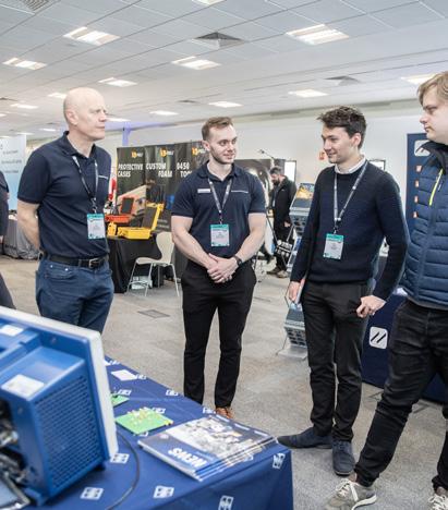


GI Systems Ltd
HEAD acoustics UK Ltd
Hopespare Limited
Hottinger Bruel & Kjaer
ICE Electronics
IDT (UK) Ltd
Imetrum Limited
IndySoft Europe Ltd
INNOVATEST UK Ltd
Instron
Interface Force Measurements
Intrepid Control Systems
IPETRONIK GmbH & Co. KG
Kistler Instruments Ltd
m+p international UK Ltd
Metalitest Ltd
Moog
Müller-BBM VAS
Novatech Measurements Ltd
ODOSOLUTIONS AB
PCB Piezotronics Ltd
Peli Products (UK) Ltd
Plastometrex
Polytec Ltd
Premcal
Prosig / DJB
RDP Electronics Ltd
Relyence UK Limited
Rohde & Schwarz UK Limited
Sensors UK Ltd
Servotest Testing Systems Ltd
Siemens Digital Industries Software
SIKA Instruments Ltd
Star Hydraulics Ltd
Strainsense Limited
Swansea University / SMART
Techni Measure Ltd
Texys International
THP Systems Ltd
Torquemeters Limited
VBOX Automotive (Racelogic)
Vector GB Ltd
Vibration Research Corporation
Vishay Measurements Group Ltd
Vision Research Inc
Yokogawa UK Ltd
ZwickRoell & CATS3 Ltd
Throughout the day, visitors can attend a series of mini seminars presented by leading industry experts, covering topics at the forefront of engineering, such as artificial intelligence, data-driven decision-making and the evolution of data acquisition technologies. These short presentations offer valuable insights for professionals seeking to stay ahead in a rapidly evolving field.
AI for Integrity and Measurement Engineers
Ali Parandeh, ADSP (see page 31)

From Paper Streaming to Data Streaming; 40 years of Data Acquisition
Iain Godwin, Axiometrix Solutions
Turning Testing Data into Decisions: A Series of Case Studies
Adam Buckell, Frazer-Nash Consultancy Ltd
Smart Batteries to Electrify Transportation: Characterisation, Safety and Management
Tim Vincent, WMG
The Role of Digital Twins and Multiphysics Modelling in the Testing of Aerospace Propulsion Systems
Adam Harris, Rolls-Royce
For full details including abstracts and timings please visit our website.
Vehicle Display
Vintage Test Equipment Display MINI SEMINARS
In recognition of our 40th anniversary, the exhibition will feature a display of vintage test equipment, offering a fascinating glimpse into the evolution of testing technologies. This exhibit is sure to be of interest to both seasoned engineers who may have used these tools in the past and younger engineers seeing them for the first time.
Call For Exhibits: Vintage Test Equipment Display
As part of our 40th-anniversary celebration, we invite contributions for a special Vintage Test Equipment Display at the Engineering Integrity Society’s Instrumentation, Analysis, and Testing Exhibition on 29 April 2025, at the Silverstone Race Circuit. This unique exhibit will showcase the evolution of testing technologies, offering a nostalgic journey for more experienced engineers and an educational experience for the next generation. If you have vintage test equipment that you'd like to display, we’d love to hear from you! Contact Marketing & Events Manager, Sara Atkin (info@e-i-s.org.uk).

Upon arrival visitors will be greeted by a small display outside the entrance to the Silverstone Wing, with a number of exhibitors demonstrating instrumented vehicles. This includes an innovative leap in sustainable transport technology: the ZEAP (Zero Emission Air Power) compressed air-powered vehicle. Developed by Airtech Ventures, ZEAP showcases a groundbreaking approach to zero-emission mobility and will be on static display throughout the event (see overleaf).
In addition, Oxford Technical Solutions will showcase their advanced sensor fusion capabilities through a live robot demonstration. Visitors will see how technologies like LiDAR Inertial Odometry (LIO) enable precise navigation and mapping in GNSS-denied environments, paving the way for reliable autonomous operation indoors.
To find out more and register for the event visit our website: www.e-i-s.org.uk.
Experience the Future of Sustainable Transport

Visitors to the Instrumentation, Analysis, and Testing Exhibition will have the unique opportunity to witness an innovative leap in sustainable transport technology: the ZEAP (Zero Emission Air Power) compressed air-powered vehicle. Developed by Airtech Ventures, ZEAP showcases a groundbreaking approach to zero-emission mobility and will be on static display throughout the event.
A ‘breath of fresh air’ in vehicle design, ZEAP aligns with the L7e (Types A, B & C) Heavy On Road Quadricycle category, with an unladen mass under 450 kg for transport of passengers, 600kg for transport of goods and a maximum design speed of ≤90 km/h. This lightweight yet robust design makes it ideal for urban and industrial applications where operating efficiency, hazardous operating environment capability and earth friendly environmental impact are key considerations.
Prototype upgraded in 2021, the ZEAP project has undergone extensive computational fluid dynamics (CFD) analysis, with support from a Scottish Enterprise grant, to optimise the performance of its pneumatic
motor. The current Gen 2 motor exemplifies the success of these efforts, delivering efficiency and power suited to real-world applications.
ZEAP is perfectly suited for last-mile delivery services, with a design range of 40 km and a top speed of 40 km/h on a single compressed air charge. Its versatility extends to industrial settings, such as passenger terminals and electronics facilities, where the vehicle's clean exhaust and minimal electrical noise offer significant advantages.
At the heart of ZEAP's powertrain lies a lightweight, high-pressure air storage cylinder (350 bar), precisionengineered motors, and an intelligent drive-by-wire throttle system. This combination ensures balanced power delivery and optimal energy utilisation efficiency.
Representatives from Airtech Ventures will be on hand at the exhibition to discuss the design, development and future applications of ZEAP. This is a rare chance to gain insight into the engineering expertise driving this revolutionary vehicle.

Engineered for Precision
Ÿ Pressure scanners
Ÿ 3D Flow measurement and visualisation system
Ÿ Temperature scanners
Ÿ Resistance standards
We are experts in high-accuracy measurement solutions. Check out our range of world-leading Pressure, Temperature and Electrical Measurement Instruments.
How we can help you?
Ÿ Flow probes
Please briefly explain your current role and involvement with AI.
I started my career as a mechanical engineer and gradually transitioned into the AI field. Since my transition, I’ve authored a book on productising generative AI and in my current role, lead an engineering team to build AI systems tailored to each business. These systems help automate workflows, reduce costs and enhance insights-driven decision- making for our clients.
How would you say your industry has evolved over the past five years?
Over the past five years, the industry has seen a significant shift toward digitisation and the adoption of AI and machine learning. Traditional manual processes have increasingly been supplemented or replaced by AI tools, allowing for more precise predictions, faster decision-making, and improved safety. The integration of IoT devices has also enabled real-time data collection, opening up new opportunities for leveraging AI technologies in the industry.
What is the main challenge in the field of AI at the moment?
The main challenge in the AI field is maintain transparency, reliability and ethical use of AI. Issues such as algorithm bias, the need for high-quality data, and the reproducibility of AI models remain significant adoption barriers alongside difficulties finding talent, identifying appropriate business case and collection of high-quality data. Additionally, there is a growing concern about AI’s carbon footprint and the difficulty of scaling these technologies across existing complex systems.
What developments are going on in your industry that could have an impact on the future of engineering?
Developments in predictive analytics, autonomous inspection systems and generative AI tools in digesting ever-expanding engineering documentation are shaping the future of engineering. Furthermore, advances in AI for anomaly detection, coupled with edge computing for real-time processing, are setting new standards for efficiency and safety.
Can you briefly explain what excites you most about the current state of AI?
What excites me most is AI's ability to uncover patterns and insights in data that were previously inaccessible. In addition, today’s AI tools, particularly in natural language processing and generative AI, has created new opportunities to simplify complex engineering tasks and surfacing the right knowledge at the right time across large multi-disciplinary teams.
How do you see AI influencing the role of engineers and the skills they’ll need in the future?
AI is redefining the role of engineers by automating their routine tasks, allowing them to focus on high- level problem-solving and innovation. Engineers will need to gain skills in data analytics, programming, and AI model interpretation. Soft skills, such as adaptability and cross-disciplinary collaboration, will also become increasingly important as AI continues to integrate into engineering workflows.
60 Seconds With Ali Parandeh
Head of Engineering, ASDP

What are some challenges industries might face as they adopt AI technologies for measurement and testing?
Industries may face challenges like the need for significant upfront investment in AI talent and tools, while integrating with legacy systems. Managing the change in workforce dynamics as automation takes over traditional roles is also another concern. Ensuring data accuracy and mitigating bias are other concerns when adopting AI in areas such as measurement and testing.
What trends in AI do you think engineers and businesses should keep an eye on in the next few years?
Key trends to watch for include the rise of explainable AI (XAI) tools for better transparency and the better affordability of edge computing platforms like NVIDIA Jetson devices for real-time AI applications. Language models are also more accessible, giving rise to new tools that need to crunch lots of textual data. The development of ethical AI frameworks and regulations like the AI EU act is another crucial area that businesses and engineers should monitor closely.
In your opinion, what should schools, colleges and universities do about embracing AI for engineering?
Educational institutions should integrate Python, AI and data science into engineering programmes, by focusing on both the theoretical knowledge and practical aspects. Offering interdisciplinary programs that combine engineering with computer science, ethics and business can prepare students for AI- driven roles. Additionally, fostering partnerships with industry leaders for hands-on projects and internships can bridge the gap between education and real-world needs.

ACM Hints & Tips
With David Ensor
A column with useful hints, tips or ideas on analysis, collection and measurement.
Engineers often need to measure the dynamic displacement of components, and a common assumption is that accelerometer data can provide this information. However, it’s not as straightforward as simply integrating the data twice. Theoretically, displacement is calculated by integrating acceleration to get velocity and then integrating velocity to get displacement. But this approach doesn’t always give the correct displacement, especially for general road load data type testing. For example, I once investigated a failure for a client where the wiring for a light mounted in the vehicle headliner was damaged due to flexing. The light fixture was moving relative to the wiring loom, causing the failure. This large structure was visibly bouncing up and down. The client’s initial approach was to attach an accelerometer and collect data. However, the accelerometer data alone didn’t help in understanding the problem. They asked me if the data could be integrated to get a displacement history for use in a rig test.
Here’s where problems arise. While the data is easy to collect, it quickly becomes nonsensical when converted to displacement. The initial integration of accelerometer data gives displacement results in the range of several meters in all axes, which didn’t make sense. Many engineers overlook that an accelerometer not only measures the local vibrations of interest but also includes accelerations from the entire vehicle. When you integrate this data, you get the overall movement of the vehicle, which includes bumps, hills, and other low-frequency movements caused by the road surface.
One way to address this is by using a high-pass filter to remove low-frequency data. This can work for typical Noise, Vibration, Harshness applications, where you’re interested in higher-frequency vibrations. However, for larger low-frequency displacements (like those from a headliner or suspension), this method may not be effective. These low-frequency movements often overlap with road surface variations at typical driving speeds. Another challenge is that determining the right filter settings or type is difficult. So, here’s my recommendation: if you want to accurately measure relative displacements of components, use displacement transducers. They provide direct, stable results without the need for filtering, and they avoid the complications that come with integrating accelerometer data. The only additional consideration is how to mount the transducers, but the extra effort is well worth it.
If you are interested in more detailed theoretical or practical aspects of integrating accelerometer data to displacement, I am happy to help. There are some interesting articles and papers on the subject.
Jaguar Land Rover Driving Experience


Christopher Burke was the lucky winner of the ‘Jaguar Land Rover Driving Experience’ from the prize draw held at the Instrumentation, Analysis and Testing Exhibition. In August, Chris visited the centre in Solihull and we were keen to find out about his exciting day.
How did you feel to win the prize? Surprised and delighted.
Did anyone attend the experience with you?
It was just me – but it did mean I had more time with the instructor and was able to progress to some of the more advanced challenges on the course.
Have you ever done anything similar before, or was this a completely new challenge for you?
I have had flying and surfing lessons – this experience was more accessible and a lot less strenuous!
What happened on the day? What did the experience involve?
It was a very enjoyable day and the new Defender is an impressive and fun drive. We started on an artificial mound to demonstrate how the vehicle handled a large sideways tilt – then we got on to the main course which started with a very steep hill. As we went on the turns got tighter and the route got more restricted. Our average speed was about 3 mph. The Defender has a suite of genuinely usable driver aids like computer generated views stitched together from various cameras so you can see just how close you are getting to that tree trunk…
What was your favourite part of the experience? Any highlights?
The highlight of the day was navigating a stream on the course, almost subtropical. I learned that one meter of water is the most you would want to drive in – after that the Defender starts to behave like a boat!
Would you do something like this again? Are you now tempted to explore more off-road adventures? I can thoroughly recommend the experience – if you’re going with friends, book the whole day so you all get a go and progress to some of the more advanced challenges. My next ambition is to learn scuba diving…

REDUCE ELECTRICAL NOISE INTERFERENCE WITH PCB PIEZOTRONICS SERIES J356A4
Mitigate EMI by reducing electrical noise and ground loops with PCB’s J356A4 series. These hermetically sealed, ground isolated miniature triaxial ICP ® accelerometers are:

MODEL J356A43
n Sensitivity: (±10%) 10 mV/g
n Measurement Range: ±500 g pk
n Frequency Range: (±10%) 0.4 to 10k Hz
MODEL J356A44
n Sensitivity: (±10%) 50 mV/g
n Measurement Range: ±100 g pk
n Frequency Range: (±10%) 0.4 to 10k Hz
MODEL J356A45
n Sensitivity: (±10%) 100 mV/g
n Measurement Range: ±50 g pk
n Frequency Range: (±10%) 0.4 to 10k Hz
n Electrically Isolated (1 x 10⁸ ohm)
n Lightweight (0.15 ounces / 4.2 grams)
n TEDS IEEE 1451.4 enabled

Pulses, Tones, and Whines: Understanding Electric Vehicle Noise and How To Measure It
Scan QR to Watch the Video!

Product News
ODOS unveils game-changing DoIP Dongle for EV testing teams
The automotive industry is rapidly evolving, and the shift towards Zero-Emission Vehicles (ZEVs) brings new challenges in ECU development and diagnostic testing. In response, ODOSOLUTIONS (ODOS) is excited to introduce its innovative DoIP Dongle, a state-of-the-art datalogger designed to streamline testing processes for electric vehicle (EV) development teams.

Specifically crafted to meet the requirements of SAE J1979-3, the DoIP Dongle is more than just a tool – it’s a critical enabler for optimising the Design Verification Plan (DVP) process in ZEV software testing. This ensures developers have the precise data insights needed to enhance performance and compliance. With the US market set to enforce mandatory adherence to SAE standards for the 2026 model year, this device is poised to become an essential asset for meeting regulatory demands efficiently. By bridging the gap between advanced diagnostics and compliance, the DoIP Dongle empowers teams to stay ahead in a rapidly changing landscape.
www.odosolutions.com
Global real-time data management
With IPEcloud2, IPETRONIK introduces a powerful, cloudbased platform for efficient fleet management and comprehensive data analysis. The platform enables realtime management, global sharing and detailed analysis of vehicle data. Thanks to high scalability, hundreds of vehicles can be centrally controlled, providing immense relief especially for fleet managers and engineers.
IPEcloud2 offers extensive features for monitoring, diagnosing and analysing the state of the vehicles. Realtime analyses allow for early detection of trends and informed, data-driven decisions. Fleet managers have full control over the condition and performance of their vehicles at all times. The flexible remote functionality allows tests and analyses to be conducted regardless of location, saving time and resources as engineers no longer need to be physically present in the vehicle.
With support for over-the-air updates, test cases and software versions can be quickly adjusted to ensure efficient operations. The high-security standards of IPEcloud2 guarantee encrypted data transmission and
secure access. Unlimited storage capacity ensures that all important information is securely stored and retrievable, while automatic data uploads facilitate smooth data management. Discover IPEcloud2 now and optimise your fleet management processes!
www.ipetronik.com
New low-noise microphone from PCB Piezotronics expands testing capabilities
PCB Piezotronics has introduced the Model 378A08, a ¼" (6mm) free-field microphone system designed for applications requiring extremely low-noise measurement. With a sensitivity rating of 50 mV/Pa, the 378A08 achieves a low-noise floor of 25 dBA (22 dBA typical) – comparable to larger ½" microphones –making it ideal for precision acoustic testing.
Unlike traditional ¼" microphones, which typically have lower sensitivities and struggle with low-amplitude sound capture, the 378A08 provides a versatile solution with multiple sound field capabilities. While optimised for free-field applications, it can also be used in diffuse and pressure fields, eliminating the need for multiple microphones in diverse testing environments. Its compact sise minimises disturbance to the sound field, ensuring accurate high-frequency measurements.
The 378A08 is well-suited for applications in automotive and aerospace cabin noise testing, electric vehicle acoustics, component evaluations, and consumer electronics such as computer fans and disk drives. Engineers conducting low-noise testing now have a compact, high-performance alternative that simplifies data collection while reducing overall testing costs.
With the launch of the 378A08, PCB continues to expand its portfolio of acoustic sensors, offering reliable solutions for industries requiring precision sound measurement.
www.pcb.com
Sensor Technology launches innovative SGR570 TorqSense PTO torque transducers for enhanced power take-off monitoring
The new product line delivers accurate and reliable torque measurement for agriculture, construction, and industrial applications.
Sensor Technology Ltd, a leading innovator in the field of torque transducers, is excited to announce the launch of its latest product line SGR570 TorqSense range. These advanced sensors are designed to provide precise and reliable torque measurements for Power Take-Off (PTO) systems, catering to a wide range of applications in agriculture, construction and industrial machinery.
The new SGR570 TorqSense range PTO torque transducers are engineered to meet the growing demand for accurate performance data in heavy-duty
equipment, where monitoring the power and torque delivered through PTO systems is essential for optimising operational efficiency and equipment longevity. Built with cutting-edge technology, these transducers offer a robust, easy-to-install solution for manufacturers, operators, and maintenance teams seeking to enhance machine performance and reduce downtime.
Key Features and Benefits:
• High Accuracy: Offering superior torque measurement accuracy, the transducers are ideal for applications requiring precise performance monitoring, enabling better decision-making and real-time adjustments.
• Durable Design: Engineered for harsh environments, the new transducers are housed in rugged, weatherresistant casings to withstand the demanding conditions found in agriculture and construction industries.
• Seamless Integration: The PTO torque transducers are designed for easy installation and integration with existing PTO systems, providing reliable and consistent data without the need for complex modifications.
• Wireless Connectivity: Options include wireless data transmission capabilities, allowing operators to monitor torque levels remotely via digital displays or mobile devices.
•Cost-Effective Maintenance: By providing accurate real-time torque measurements, the transducers help prevent equipment overload and mechanical failure, reducing maintenance costs and extending the life of machinery, offering the same output features as the SGR520 TorqSense range.
www.sensors.co.uk
Power and efficiency measurement with a new LITE-PA power analyser from StrainSense
StrainSense are excited to present Dewetron’s new LITE-PA power analyser system. With high accuracy electrical power measurement, speed and torque inputs for mechanical power, real-time efficiency mapping and testbed interfaces, it’s ideal for industrial motor, component, end-of-line and white-good test applications. Voltage inputs have ±2kV peak range, 2 MHz sample rate, 24-bit resolution and CAT IV safety rating. Sub modules are available for all types of current sensors and direct current inputs up to ±40A peak are available. High precision power measurement accuracy is 0.04% over a class-leading wideband range from 0.5 to 1000Hz.
Digital inputs for speed and torque are included as standard, to measure mechanical power in synchronisation with electrical power. Efficiency maps

over the operating speed and torque range are produced in real time.
Standard instruments are scopes, power meters, phasor diagrams, harmonics tables and efficiency maps. Efficiency maps and all other instruments can be exported as PDF reports.
Power data is displayed in the intuitive Oxygen software on a 11.6” wide-screen full HD display. A 19” rack mount kit is available. Oxygen can be installed on multiple PCs licence free for analysing recorded data in postprocessing.
Testbed interfaces are CAN and Ethernet (SCPI, XCP, UDP) for testbed automation. The CAN interface can also be used for our XR-TH8-S temperature modules. The LITEPA power analyser system is available with four or eight power channels.
www.strainsense.co.uk
Knowing the right trigger strategy ensures capture of high-speed applications with precision
In high-speed imaging, precision is crucial for capturing fleeting moments vital to engineering analysis. Phantom high-speed cameras provide versatile triggering methods to meet diverse needs, from controlled laboratory experiments to unpredictable real-world scenarios. Choosing the right trigger strategy ensures reliable results and efficient resource utilisation. A trigger defines the moment when a camera shifts from continuous recording to preserving event-specific data, enabling engineers to analyse high-speed events accurately. Key triggering strategies include:
• Contact Closure and Opening Switch: A straightforward method using BNC cables, ideal for synchronised, longdistance setups.
• Transistor-Transistor Logic (TTL) Trigger: Preferred for synchronised systems, leveraging third-party devices for precision.
• DC Voltage Trigger: Aligns frames using higher voltage thresholds, suitable for complex setups.
• Software Trigger: Operates through Phantom Camera Control (PCC) software, effective for standalone setups but not for synchronisation.
• Image-Based Auto Trigger (IBAT): Detects motion in the field of view, perfect for unpredictable events.
• On-Camera Controls: Enables quick manual triggering in isolated setups without additional hardware.
Advanced features like middle triggers allow capturing pre- and post-event frames, essential for ultrafast event analysis. Synchronisation tools ensure precise frame alignment across multiple cameras, enhancing accuracy in scientific and industrial applications. Phantom cameras empower engineers to tackle the challenges of highspeed capture, enabling precise analysis, innovative design and informed decision-making with confidence. If you want to know more tips and tricks for using highspeed cameras in your research, check out the Vision Research knowledge base.
https://phantomhighspeed.com
CONTROL CUBE & CUBUS


Corner strain gauge: Measure closer than before
Sensors UK Ltd is pleased to announce the latest addition to the market leading KFGS general purpose strain gauge range. The KFGS-1NE now allows you to measure even closer to stress concentration areas from only 0.4mm from the tip of the strain gauge to the sensor element for applications where measurements close to the stress concentration such is critical.
Designed for general purpose, static and dynamic stress analysis, the KFGS strain gauges from Kyowa still have the world's highest level performance with a polyimide resin base that ensures excellent flexibility with outstanding moisture proofing enabling the KFGS gauges to operate in outdoor measurement environments effectively with no additional coating treatments unless directly exposed to water. This new gauge expands the broad range offered from general purpose to specialist units for measurement in hostile environments such as hydrogen gas, offshore and low/high temperatures to designs for a variety of materials making them ideal for various application including structural health monitoring, automation, offshore, robotics and condition monitoring.
www.sensorsuk.com
Drive System Design unveils a new EMC test cell to power next-generation electronics development capabilities
Drive System Design (DSD), a leading engineering and mobility consultancy, has expanded its development and testing capability by commissioning a state-ofthe-art EMC (electromagnetic compatibility) test cell at its Wellesbourne facility in the UK. This strategic investment strengthens DSD's role as a development and test partner for advanced power electronics and electrified propulsion systems, furthering its mission to drive innovation within the electrification space.
insights from complex datasets, providing clear dashboards and comprehensive reporting capabilities that empower users to act swiftly and decisively. ReliaSoft Cloud by ReliaSoft is a web-based Software as a Service (SaaS) solution designed for centralised FMEA management. Combining global accessibility with IT security, it empowers teams to collaborate seamlessly from anywhere. ReliaSoft Cloud effortlessly scales to meet the needs of both small teams and large enterprises, with simplified deployment and customisable features. Users can drive smarter reliability processes with AIenhanced tools and interactive dashboards, enabling effective risk visualisation and streamlined tracking of design improvements for better decision-making. Both products reflect HBK’s commitment to driving innovation and empowering engineers with innovative tools that bridge the gap between testing, analysis and design optimisation. To learn more about these solutions, visit hbkworld.com.
HARMAN
chooses GRAS ¼” microphones for measurements in system engineering
In their continuing quest for unsurpassed in-vehicle audio quality, the Automotive Acoustic Systems Engineering department at HARMAN International has chosen the GRAS 46BL-1 microphone set from GRAS Acoustics for their new measurement arrays for calibrating their highend vehicle sound systems.


Your Partner in Dynamic and Static Testing


The new EMC test cell enables DSD to grow its electronics capability beyond design and simulation and now offers enhanced development and verification testing of power electronics and electrified propulsion systems. Purposebuilt to conform with CISPR 25 and BS EN 50147 industry standards, the 144m3 semi-anechoic chamber allows DSD to conduct EMC tests that can enable the highest level of performance. This advanced facility is supported by a dedicated engineering team with expertise in diagnosing and resolving EMC-related challenges.
www.thisismc2.com
HBK launches two new software products: ReliaSoft Cloud and Advantage Insights
HBK (Hottinger Brüel & Kjær) is proud to announce the launch of two innovative software solutions –ReliaSoft Cloud and Advantage Insights – introducing new advancements in our reliability engineering and durability data analysis offering. These new tools became available to customers in November and are set to elevate the way engineers harness data for optimal performance and decision-making. Advantage Insights by nCode transforms raw sensor and CAN data into actionable intelligence. With advanced analytics and visualisation tools, engineers can identify patterns, track trends, and make informed decisions to enhance product design and performance. This software simplifies the process of extracting
A HARMAN automotive sound system has anywhere between 10–30 speakers. Each of them needs to be tuned separately by listening and measuring over and over to make sure the sound in the car is optimised and achieves targets for respective brands. Going forward, HARMAN will use GRAS 46BL-1 ¼” microphones arranged in sixmicrophone arrays to cover the sound field of different head positions of the driver. HARMAN chose the GRAS 46BL-1 as they realised it was the only microphone on the market that could match their demands for a lownoise floor.
The GRAS 46BL-1 ¼” CCP Pressure Standard Microphone Set, High Sensitivity consists of a microphone cartridge and preamplifier combination, which is calibrated as one unit. Due to its small size, high sensitivity and low-noise floor, the 46BL-1 excels at in-cabin testing and measurement and fulfills the Audio Engineering Society’s (AES), recommendations for infotainment system evaluation. The 46BL-1 can be attached to the GRAS RA0399 holder, designed for holding ¼” measurement microphones in six predefined positions, simulating the head positions of a person in a car. The RA0399 array together with the GRAS 46BL-1 highly sensitive microphone sets fulfills the complete test demands in the 2023 AES white paper on in-car acoustic measurements.
www.grasacoustics.com
Contributions to Industry News may be emailed to managingeditor@e-i-s.org.uk. The nominal limit for entry is 250 words.
This paper was reproduced from the EIS Fatigue 2024 Conference Proceedings.
Technical Paper:
Fatigue Design Of Cast Aluminium Passenger Car Wheels With Respect To The Transfer Of Cyclic Material Properties
Matthias Hell
RONAL GmbH, Karl-Wirth-Strasse 100, 76694 Forst, Germany
Author correspondence: matthias.hell@ronalgroup.com
Wheels of passenger cars combine aesthetic and aerodynamic aspects and are crucial for vehicle dynamics and safety. Driven by the vehicle design and the vehicle dynamics, especially the huge weight of electric vehicles, tire widths and wheel sizes increase steadily while weight targets are lowered at the same time. Looking at the sheer numbers of produced wheels around the globe, the impact of weight reductions on energy consumption and emissions for production and vehicle usage are obvious. Weight optimisations of the wheel require design iterations which entail a large number of fatigue life and manufacturing simulations. The applied models have to be simple enough to be manageable in everyday practice and complex enough to capture all relevant influencing factors. The paper therefore presents an advanced weakest-link approach that extends the original formulation by a localised material behaviour. It allows the consideration of manufacturing influences and inhomogeneous property distributions. The parametrisation of the approach can be based on material testing with specimens as well as knowledge from prior component testing. The application of the approach reduces uncertainties in the fatigue estimation and allows an increase in material utilisation without diminishing safety margins.
Keywords: Numerical Fatigue Assessment, Size Effects, ComponentStrength,DamageAccumulation
CHALLENGES FOR FATIGUE ESTIMATION AND COMPONENT OPTIMISATION
Modern, complex wheel designs differ a lot from classical periodic and symmetrical radial spoke or mesh designs. Stress concentrations result from loading gradients (bending and torsion) and the component geometry. Depending on the design, a fully three-dimensional stressstrain state beneath the surface is present already during uniaxial loading and even simple cyclic load cases may lead to rotations in the principal stress direction. In case of unfavourably oriented anisotropic microstructures, this effect may lead to an additional reduction in fatigue performance, as discussed by Scurria et al. [1]. Moreover, usual service load time functions contain overloads or misuse manoeuvres, which could provoke locally limited plasticity, even if no structural yielding occurs. Figure 1 shows the result for the simulation of a revolving biaxial load from ZWARP testing. The load case (maximum load case cornering) results in an excess of the yield limit in a wider area on the spoke in-line with the radial force and different locally confined plastic zones at the transition of spoke to hub and at the radii of the window between the spokes.

Load spectra for passenger car wheels and other safety critical components are usually scaled up in order to reduce testing times. This aggravates the challenge of describing the actual stress-strain state, which is preliminary for a sufficiently accurate fatigue life estimation and a consequent lightweight design optimisation. The locally limited plasticity depends on the remaining elastic cross section, which defines the boundary conditions for the cyclic deformation. In this case, the local elasto-plastic stress-strain path can only be described correctly, if the material model is suitable for an evaluation of the local strain response and the resulting shift of mean stresses by localised plastic straining. The strain-life approach allows the usage of arbitrarily complex material models and provides a strain-life relation applicable to the LCF as well as to the HCF regime. At the same time, the number of experiments required for the definition of the material and fatigue behaviour is severely reduced in comparison with the nominal stress approach, if the data from the fatigue and component testing is exploited thoroughly.
STATE-OF-THE-ART FATIGUE ASSESSMENT FOR CAST ALUMINIUM WHEELS
In most cases a practical and simple nominal stress approach will be applied on basis of a material S-N
curve and different correction factors. Ramamurty Raju et al. [2] evaluated the fatigue life based on numerical simulations for the cornering fatigue test and fatigue data from rotary bending tests with specimens extracted from the spoke of the wheel. Size and mean stress effects are not considered. Wang et al. [3] apply a nominal stress approach with different correction factors for component size and notch effects. Li et al.[4] describe a through process modelling approach, which estimates residual stresses and microstructures based on the process parameters.
Other work without limitation to the application for wheel fatigue analysis frequently focusses on the role of defects, especially pores. A good comprehensive overview over influencing factors on the fatigue behaviour of A356 and possible practical approaches to deal with the influence of mean stresses, defects and component size is presented by Nourian-Avval and Fatemi [5]. The influence of defects and the statistical size effect is treated with the Kitagawa-Takahashi Diagram and the El-Haddad criterion for the intrinsic crack size. The approach shows good results for specimens also under consideration of the influence of casting surfaces and realistic process routes. In turn, the approach requires a profound characterisation of the defect status, presented by the authors in [6]. In order to estimate fatigue limits for a new component geometry or variable process parameters from a draft, a validated process simulation with a forecast of the defect position and morphology may be required.
The very simple nominal stress approaches are limited with respect to the transfer between components with significant changes in the geometry, the loading or the process parameters, because stress- or material-gradient effects are only considered by correctional factors. The physically sound models based on fracture mechanics on the other hand yield good results but are in most cases too complex for design iterations with a large number of calculations. Therefore, the paper focusses on simple methods in order to implement the influence of material and stress gradients on the fatigue life in order to improve the fatigue life estimation.
INTERACTION BETWEEN MATERIAL, LOADING, GEOMETRY AND MANUFACTURING
The local strain response governs the fatigue performance and is governed by the complex interaction of the loading, the component geometry and the manufacturing related material behaviour and morphology, as Figure 2 illustrates schematically. Nearly all manufacturing steps and processes leave their fingerprint in the material and cause local inhomogeneities and property gradients throughout the component volume.
The manufacturing-induced property gradient is superimposed by the stress gradient resulting from the interaction between external loading and component geometry. The strain response of the material to the loading therefore represents a combination of the stress and material gradient. It drives the local fatigue processes, starting with a crack nucleation at defects over a short crack growth up to stable crack propagation and final structural failure of the wheel. The constant degradation

processes, marked by the movement, generation and annihilation of dislocations and dislocation structures, also changes the stress-strain behaviour continuously. A valid evaluation of the strain response requires the numerical modelling including the influence of defect and property gradients. At the same time, the numerical model has to be efficient and lean enough to be applicable during the draft phase with a large number of optimisation iterations. The proposed modification of the weakest-link approach provides an interface for the consideration of loading and material gradients based on the statistical evaluation of the local material behaviour and the manufacturing influence. It allows the transfer of fatigue properties between the specimen and component as well as between components with different geometry.
STRAIN-LIFE APPROACH AND TRANSFER METHODS FOR THE CONSIDERATION OF SIZE EFFECTS
In load-based linear-elastic approaches the transfer of fatigue properties from the specimen to the component level requires different transfer approaches for the consideration of relevant influencing factors. The influencing factor related to the localised plasticity of notched or inhomogeneous loaded components is described as the notch support effect. It is related to the phenomenon that notched specimens endure a larger number of cycles to failure than the calculated elastic notch stress would suggest on the basis of the S-N curve for the un-notched material. It is superimposed by different size effects, which were defined by Kloos as statistical, mechanical, surface related and technological size effects. [7] In the load-based linear-elastic approach, it is challenging to experimentally assess or treat those effects separately. The available methods usually represent a superposition of different size and notch support effects. This circumstance limits the

Figure 1: Local stress response to simple biaxial loading.
Figure 2: Cross-relations between manufacturing, geometry, material properties, loading and strain response.
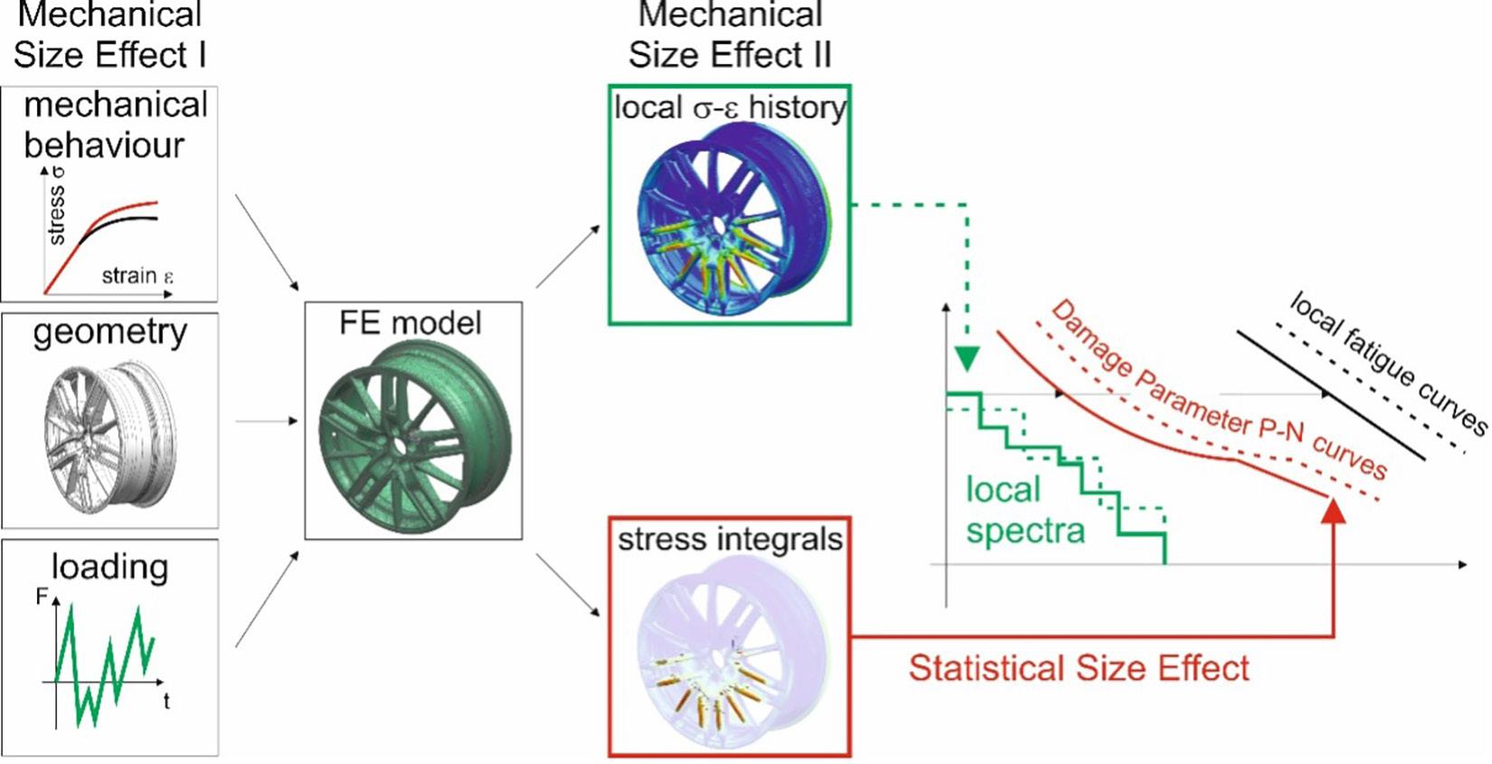
transferability to more or less narrow variations of loading scenarios, material gradients and component geometry. The main advantage of the elasto-plastic strain-based approaches in this respect is the possible abstraction between the modelling of the strain response and the treatment of stochastical phenomena.
The fundamental assumption of the classical strainlife approach is the equivalence between the material behaviour of an infinitesimal small volume at the notch root and a homogeneously loaded specimen of the same material. This assumption has to be amended by considerations of different types of size effects. Figure 3 shows a strain-life fatigue approach with interfaces for the consideration of different possible size effects. With the elasto-plastic material behaviour, for example acc. to Ramberg-Osgood, the component geometry and the load-time function, a FE model is set up. From the solution of the model the local stress-strain history as well as correlation measurements (gradients and highly stressed volumina) are obtained. It has to be denoted that also the extension of highly stressed volumina and the stress gradient explicitly depend on the load-time history. Starting at local peak stresses, the local damage is calculated based on the full - field data. The spectrum of the local stress-time history is then processed with a local damage accumulation against Damage Parameter P-N curves, which are derived from the strain-life curve and implement the influence of mean stresses on the fatigue performance. The P-N curves are modified by a modification of Weibull’s weakest-link theory, which accounts for possible deviations in the defect distribution and differences in local fatigue performance.
Mechanical Size Effect I denotes a scale dependency of the material properties. For polycrystalline materials with well-dispersed microstructural morphology the material behaves homogeneous, if the length scale of the examined specimen is large with respect to the microstructural lengths (grain size, dendrite arm spacing, etc.) and the specimen is homogeneously loaded. For real-life components, this is generally not the case. Manufacturing-induced anisotropy and local variations in the microstructure are superimposed by
gradients of the stress or strain field. In addition, variable amplitude loading may trigger anisotropic behaviour under certain orientations by rotating directions of the principal stresses. It is necessary to account for these effects during finite element modelling. Therefore, the local material behaviour has to be assessed either using full field strain measurements or small-scale specimens extracted from real-life components with comparable manufacturing parameters. In the sense of Kloos’ original definition of size effects in linear-elastic approaches, Mechanical Size Effect I corresponds to the technological size effect.
Mechanical Size Effect II is strongly related to the extension of the plastic zone relative to the remaining elastic cross section. The deformation boundary conditions of local material depends on the straining of the surrounding material. If the cross section is loaded with a constant stress, the load ratio of the external load is equivalent to the stress-ratio of the local stresses. If, at notches or in the general case of components with a complex shape, stress gradients are present, the material yields only locally. If the plastic zone is small compared to the remaining rest cross section, its deformation will be strain-controlled. On unloading after tensional yield, the remaining cross section will induce compressive stresses in the highly stressed material volume. If the yield zone is large compared to the remaining cross section, the residual strains in the yielded volume will induce tensional stresses in the surrounding material. Especially under variable amplitude loading, this effect leads to a pronounced load sequence effect, which is already well established and discussed for fracture mechanics approaches. In order to account for this size effect, it is necessary to evaluate the strain response considering the effects of stress gradients. The external load-time function has to be transferred to the local strain-time function before counting algorithms are applied. Otherwise, changes in mean stresses may be ignored, leading to inaccuracy in the damage accumulation.
The Statistical Size Effect is related to the natural scatter of the fatigue properties. It depends on the dispersion and the morphology of defects. In cast components,

the defects, such as, for example, voids, porosity, segregations, inclusions, depend on the manufacturing parameters and are seldomly distributed homogeneously throughout the material volume. The defect influence can only be described correctly if the local defect distribution can be assessed with manufacturing simulations or with measurements (X-ray, tomography etc.). Different approaches have been proposed for the consideration of size effects. A modified weakest-link approach is able to capture the local property gradient and differences in defect population.
Experimental Analysis of the Local Cyclic Material Behaviour
For cast aluminium passenger car wheels, AlSi7Mg0,3 alloy (A356) is widely in use. The cyclic material behaviour on the casting process as well as the consecutive heat treatment by solution annealing and artificial ageing. The cyclic material properties and the microstructure show a large dependence on the casting and heat treatment parameters and will be distributed inhomogeneously
throughout the material volume. The effect of different microstructures on fatigue for A356 is described, for example, by Houria et al. [8] and in [9,10].
In order to assess the influence of the manufacturing influenced behaviour and to account for material gradients, an extraction schematic as shown in Figure 4 was used. The extraction positions cover the Hub region, the spoke, the transition between the spoke, bed and tire seat and the bed/well. Due to the casting parameters and the mass distribution with respect to the heat treatment by solution annealing and artificial ageing, those regions usually show different material properties with respect to tensile strength and strain at break.
The applied specimen geometry is shown in Figure 5. The specimen blanks were conventionally manufactured from the wheel and then electric discharge machined to the final geometry.
The tests were all executed in strain-control with a Sandner clip-on strain gauge on a ZWICK Rel 2100 Test System with an Instron 8800 Acquisition and Control

Figure 3: Strain-life approach with interfaces for the consideration of mechanical and statistical size effects.
Figure 4: Extraction pattern for the experimental examination of the local material and fatigue behaviour.
Figure 5: Specimen geometry applied for testing.

System, see Figure 6. For tests with high strain amplitude, a buckling support was employed (not visible in the Figure).
From the test results, cyclic deformation curves were derived, in order to assess the cyclic stabilisation and crack initiation cycle numbers. The point of crack initiation is determined recursively from a 5 % drop in the load at the tensional load reversal point, see Figure 7 (below).
Figure 8 (opposite page) shows, that cyclic hardening can be observed for all three extraction positions. The initial loading curves and the stabilised hystereses differ substantially. The same is true for the stabilised stressstrain curves acc. to Ramberg-Osgood, evaluated at half the number of cycles to crack initiation.
MODIFIED WEAKEST-LINK APPROACH FOR THE CONSIDERATION OF SIZE EFFECTS AND DEFECT DISTRIBUTIONS
The proposed modifications to the weakest-link approach [11, 12] provide different interfaces for knowledgebased information, i.e. from prior component testing, as well as for the consideration of manufacturing-induced property gradients. It is necessary to discretise the analytical functions and to numerically approximate the volume integrals as the sum over the elements in the highly stressed regions, in order to keep the effort manageable. In order to reduce post-processing times, the stress function is discretised to average values at the element centre, using the maximum principal stress criterion. The correlation object chosen is the volume. It


is also possible and recommended by some authors to correlate survival probabilities with the highly stressed area [13]. Instead of using complicated area formulations it is in this case also possible to select only elements with a boundary surface, if the element resolution is high enough. The following mathematical framework is applicable to arbitrary correlation objects.


The survival probability for a homogeneously loaded Volume Vref with also homogenous material behaviour and defect density is known from experiments and can be described using the Weibull distribution according to Equation 1, where a,ref denotes the stress amplitude for a survival probability of Ps=36,8 % for a fixed number of cycles to failure and a denotes the loading of the specimen. The shape parameter b as well as a,ref have to be statistically derived from test data (either specimen or component). In order to estimate the parameters of the Weibull distribution, also the dispersion in the direction of the number of cycles to failure can be employed, a,ref and and b ,ref. can be calculated afterwards, using the S-N curve acc. to Basquin, Equation 2. Supposing the reference Volume Vref contains a number of n infinitesimal small and therefore homogeneously loaded Volume Elements dV. The differential expression, Equation 3, describes the survival probability depending on the survival probability of the reference Volume Vref. and the local stress field a(x,y,z) for a fixed number of cycles to failure. (1) (2)


k: slope of the S-N curve acc. to Basquin (3)

For homogenous property distributions, Equation 3 delivers the survival properties for arbitrary stress fields a(x,y,z). Because a,ref, Vref, and b ,ref do not depend on the location x, y, z, it is possible to solve simple problems like an unnotched bar under a bending analytical. Especially for cast components with additional heat treatment, the material properties depend significantly on the individual local process gradients and are therefore inhomogeneous. Assuming constant cyclic material properties will lead to inaccurate results and may cause either over- or under-dimensioning of the component. In order to exploit the full potential of the material, Equation 3 is modified, admitting a location and orientation dependence of the local material properties. It is now indicated that a,ref, b ,ref and Vref may depend on the location within the component, see Equation 4.

In order to apply Equation 4 to load and process simulation FEA, it has to be discretised and linked to the element volume in order to be numerically solvable. Assuming a sufficiently high element resolution it is admissible to neglect variations of the stress over the element and calculate with averaged results for the element centre. The reference values for the local fatigue properties as well as the cyclic material behaviour have to be mapped to the element centre coordinates, x, y and z. (5)

The result of the numerical integration of the volume integrals over the local stress and property field yields a survival probability for a constant number of cycles to failure and a defined local maximum stress. Depending
Figure 7: Cyclic deformation curves (left) and stress-strain path of a fatigue test from Position 1.
Figure 8: Comparison between initial loading curves and stabilised hystereses for extraction positions 1, 2 and 3 (left), cyclically stabilised stress-strain curves acc. to Ramberg-Osgood for extraction positions 1–4 (right).
Figure 6: Test rig, detail of the clamping.

on the calculation task, it is possible either to evaluate a size effect correction of the number of cycles to failure (Equation 6) or the admissible local maximum stress for the fixed number of cycles to failure (Equation 7), also enabling a corrected calculation of the degree of utilisation (Equation 8).


NUMERICAL MODELLING AND VALIDATION
(6) (7)
consideration of locally inhomogeneous material behaviour and gradients in defect density. In the preprocessing, the local inhomogeneous stress-strain behaviour is applied to the component geometry together with the loads. After a non-linear static solution, the stress- / strain fields are superimposed with a matrix containing the local information for the strain-life / stress-life relation and the parameters for the modified weakest-link approach.
Figure 10 shows the comparison of the proposed approach with fatigue data from component release testing, a fatigue life estimation with a load-based S-N curve, the results of a calculation with local material behaviour (strain-life) and the results with an application of the proposed modified weakest-link approach. The diagram plots the normalised load amplitude vs. the number of cycles to failure.
(8)
Generally, the evaluation of integrals over the elements could be executed by Gaussian quadrature. Despite the reduction in required element size, this procedure is cumbersome and also not efficient, if solutions from different FE programs have to be mapped onto each other. It is therefore recommended to use the element centroid solution for the maximum principal stress in order to evaluate the stress integrals under the precondition, that the element size is sufficiently small. Figure 9 shows the modelling approach for the
All of the calculation results provide a conservative fatigue life estimation, taking into account that the numerical calculations refer to a survival probability of 50% for the load-based linear-elastic approach and 36.8% for the strain-based fatigue concept with a modified weakestlink approach. The local approach without consideration of size effects underestimates the experimental fatigue life at the high load amplitude L than the fatigue estimation with a load-based S-N curve. At the lower load magnitude L without consideration is already located nearer towards the experimental results. With the size effect correction by applying the modified weakest link approach, the numerically estimated fatigue life approximates the test results better than the fatigue estimation with the loadbased linear-elastic approach.

LIST OF SYMBOLS
bN,ref Shape parameter of the Weibull distribution of survival probability over the number of cycles to failure for a constant stress amplitude
bσ,ref Shape parameter of the Weibull distribution of survival probability over the stress amplitude for a constant number of cycles to failure
k Slope of the S-N curve acc. to Basquin
Nf Number of cycles to failure
Nf,ref Number of cycles to failure for the reference specimen/component
NV,SC Estimated number of cycles to failure with a modified weakest-link approach
Ps,V Probability of survival
Ps,VrefProbability of survival for the reference specimen/ component
Ps,V Probability of survival for the arbitrary component
Vref Reference volume for the weakest-link approach
σ a Stress amplitude
σ a (x,y,z) Stress field in the component
σa,ref Reference stress amplitude at Ps=36.8% (characteristic value of the Weibull distribution)
σ a,sc Admissible stress amplitude calculated with a modified weakest-link approach

REFERENCES
[1] Scurria, M., and Wagener, R., and Möller, B., and Emre, S., SAEInt.J.Eng. , Vol. 10, No. 2, 2017, pp. 366–372.
[2] Ramamurty Raju, P., Satyanarayana, B., Ramji, K., Suresh Babu, K., Eng.Fail.Anal. , Vol. 14, 2007, pp. 791–800
[3] Wang, L., Chen, Y., Wang, C., Wang, Q., J.Mech.Eng., Vol. 57, 2011, pp. 31–39
[4] Li, P., Maijer, D.M., Lindley, T.C., Lee, P.D., Mat.Sci.Eng. A , Vol. 460-461, 2007, pp. 20–30
[5] Nourian-Avval, A., Fatemi, A., Mat.Tod. Communic., Vol. 25, 2020, Publ. No. 101567
[6] Nourian-Avval, A., Fatemi, A., Materials , Vol. 13, 2020, Publ. No. 3068
[7] Kloos, K.-H., VDI-Berichte, Vol. 286, 1976, pp. 63–76
[8] Houria M.I., Nadot, Y., Fathallah, R., Roy, M., Maijer, D., Int.J.Fat., Vol. 80, 2015, pp. 90–102
[9] Dash, S.S., Daolun, C., Metals , 2023, Paper no. 609
[10] Nasr, A., Hassine, W., Maroua, S., Bouraoui, C,. Int. J. Adv.Manuf.Tech., Vol. 98, 2018, pp. 2579–2589
[11] Weibull, W., A Statistical Theory of the Strength of Metals, IngeniörvetenskapsakademienHandlingar , 1939
[12] Freudenthal, A.M., Gumbel, E.J., Proc.RoyalSoc. , Vol. A 126, 1953, pp. 309–332.
[13] Böhm, J., Heckel, K, Z. f. Werkstofftechnik , Vol. 13,

It is an opportunity to network to learn from each other. It is an opportunity to think of something or see something you never thought would happen. It is the sense of community and collaboration that is very important for our industry.

| +44 (0)20 3196 4300 advancedengineeringuk.com


Figure 10: Validation of the proposed strain-life approach with a modified weakest-link approach.
Figure 9: Numerical modelling approach for the derivation of volume integrals and the consideration of size effects.
News from the Institute of Measurement and Control


Last year saw the successful launch of our new network, Women in Measurement, Automation and Control (WiMAC). Throughout the year we continued to expand the group, forming a mission statement and set of values to help raise the profile of women within engineering industries and sectors, with the aim of cultivating a strong network of support and mentorship.
We start 2025 with a brand-new strategy which will focus on three main initiatives: mentorship and networking, STEM outreach and visibility campaigns. WiMAC is currently only open to InstMC members as we work on building and promoting the group, but we are keen to open up membership to the wider community as the network becomes more established so please watch this space! If you would like to find out more about WiMAC, please visit https://www.instmc.org/womens_network/ about.aspx.
Driven by groups of volunteers who work, or have expertise, within the relevant topic area, SIGs promote the sharing and advancement of knowledge through a range of different activities. These include producing white papers and briefing notes, as well as hosting and attending seminars and exhibitions. Some notable achievements delivered by the SIGs include:
• Two professionally registered qualifications from Functional Safety, offered exclusively to InstMC Members, in RFSE – Registered Functional Safety Engineer and RExE – Registered Explosive Atmospheres Engineer.

With the women’s network now up and running, we are turning our attention to the younger end of our membership and are currently planning the launch of an Early Careers network, primarily for those members within the first 10-year phase of their careers. Following consultation, the feedback we received suggested mentoring, career development and guidance on Professional Registration as priorities for that group. In the first quarter of 2025 we hope to have the group set up with plans for the direction it will take.
Here at the InstMC an important way for our members to network and share expertise and information is by joining one of our Special Interest Groups. We have 8 groups in total and these cover specific technical topics including Cyber Security, Digital Transformation, Explosive Atmospheres, Flow Measurement, Functional Safety, Measurement, National Metrology Skills Alliance (NMSA) and Standards. Most groups meet quarterly and are open to InstMC members and non-members alike.
• A range of reports from Flow Measurement, including one highlighting the lack of flow measurement standards for low carbon fuels such as hydrogen and another on carbon capture utilisation and storage. Both of these were sent to Downing Street with recommendations urging the government to set primary standards going forward.
• A standardised competency-based framework for metrologists that defines and provides structure for metrology skills across different levels and disciplines, created and produced by the NMSA SIG. Details of which we have previously shared in this journal.
• A set of guidelines from the Digital Transformation SIG around a range of themes aiming to help companies and businesses understand the impact of DT and to help create policies and practices within a measurement and control environment. We plan to release these guidelines to the wider public later in 2025.
If you would like to be involved or have skills to share within any of our Special Interest Groups please do consider joining and get in touch. https://www.instmc. org/sigs/about_sigs.
Jane Seery Marketing and Communications Manager
www.instmc.org
News from the Institution of Mechanical Engineers
5 Years To Go Until the UK's Clean Power Target: How Likely is Success – And How Clean Will it Actually Be?
Change is afoot in the energy system. The UK’s ‘Clean Power 2030’ target is just five years away, with increasing momentum behind the ambitious plans – but a monumental set of challenges lies ahead.
Planning and supply chain issues will put pressure on the key government policy, which needs to succeed to prevent ongoing contributions to the climate emergency. The strategy, set out last month in the Clean Power 2030 Action Plan, is also aimed at providing secure and affordable energy, and creating new related industries with thousands of skilled workers.
It is difficult to overstate the change required in the next half-decade. Recent Carbon Brief analysis found that 58% of UK electricity came from clean sources in 2024. That was the highest ever level – but way below the 95% target set for 2030.
Achieving that will require huge investment. The Action Plan targets 43–50 gigawatt (GW) capacity of offshore wind (up from 14.8 GW), 27–29 GW of onshore wind (up from 16.1 GW) and 45–47 GW of solar power (up from 17.4 GW). It also calls for 23–27 GW of battery capacity (up from about 4 GW), 4–6 GW of long-duration energy storage (up from 2.8 GW), and development of carbon capture utilisation and storage (CCUS) and hydrogen technologies.
Such significant infrastructure deployment will require a huge upgrade to the grid – twice as much transmission network will need to be built than in the last decade, according to a recent report by the National Energy System Operator (Neso), and as much offshore wind capacity will need to be contracted in the next one to two years as the last six combined.
The Neso report found that the government’s target is “achievable”, but “several elements must deliver at the limit of what is feasible”. Professional Engineering spoke to energy system experts in key policy, research and industry organisations about the chances of success.
Gas here to stay?
The new system will also involve an expected 35 GW of gas reserve capacity (down slightly from 35.6 GW, which accounted for 28% (88 TWh) of electricity generation in 2024), meaning an ongoing future for the UK’s current largest source of electricity. The residual gas power that will be used in 2030 depends on broader factors such as overall electricity demand and the level of electricity imports, added Frankie Mayo, senior energy and climate analyst at Ember.
Recent analysis by the clean energy thinktank also found that biomass generation could be reduced to just 2% of total electricity generation in 2030, down from 13%
in 2024. This could lower bills and reliance on imports while helping to reduce emissions, Ember said.
Biomass includes the large Drax power plant in North Yorkshire, which burns wood pellets from the US and Canada. The government hopes carbon capture and storage could be installed at large biomass plants, although it is so far unproven at the scale and efficiency required.
Capturing emissions is only “part of the story”, added Stuart Bradley, principal engineer at the University of Warwick’s WMG. “We also need to look at things like certain particulates,” he said. “I think if maybe more of the biomass came from the UK, rather than from Canada and the US from waste from the wood industry and furniture industry… there’s probably more of a moral case for it.”
Planning for success
Experts agreed that planning issues pose the biggest challenges to success. The planning system will need to move faster than ever for projects to achieve their potential impact.
A 2024 report by the National Engineering Policy Centre made several recommendations for rapid decarbonisation, including strong central leadership and governance with engineering at the forefront. It also called for a more flexible, “digitally enabled” system and a more proactive approach to procurement.
An international supply chain means that some energy components, such as wind turbine jacket foundations, are built elsewhere and shipped to the UK. “If we possibly can, we need to be able to encourage some of that supply chain to reshore and to cut down on the amount of carbon emissions that are associated with shipping things halfway across the world,” said Bradley.
The skills gap could be another major challenge, with persistent demand set to be compounded by the impending retirement of a fifth of the workforce between 2023 and 2028. “We have a skills gap from graduate engineers downwards all the way, all the way through; we lack people to weld, we lack people to manufacture steel,” said Bradley.
With five years to go, government and industry will have to move quickly to meet the ambitious target.
Chris Stokel-Walker
Group News


Durability & Fatigue Group
I’m delighted to take on the role of Chair for the Durability & Fatigue Group and look forward to contributing to its ongoing success. Our most recent committee meeting, held at the end of January, was a productive discussion on potential topics for upcoming events.
Hydrogen remains a particularly relevant subject in today’s evolving energy landscape, and we are currently exploring an event focused on its implications for durability, fatigue and structural integrity. Additionally, additive manufacturing and the challenges surrounding onshore renewable energy are emerging as key areas of interest. The group plans to examine these topics further, with the expectation of hosting at least one seminar later this year.
Over the past 15 years, we have delivered a series of successful renewable energy seminars, and with sustainability becoming an ever-greater priority, the importance of this work continues to grow. If you have insights, research or industry experience to share on any of these topics, we would love to hear from you. Your contributions can help shape valuable discussions and future events.
Niall Smyth Chairperson
Simulation, Test & Measurement Group
In October and November, we hosted two well-received webinars on the topic of data collection, a subject that continues to generate significant interest. The first webinar, Data Pre-processing and Denoising for Damage Detection, was presented by Andrew Halfpenny of HBK, while the second, Do You Know Your Result is the Right Result?, was delivered by David Ensor, an experienced engineering consultant. Both sessions were wellattended, and Andrew’s webinar is available to watch on our YouTube channel for those who missed the live event.
By the time this article goes to press, we will be preparing to host our next seminar, Tyre Testing & Modelling: Accelerating the Future of Automotive Innovation. Taking place at HORIBA MIRA on 20 March, this highly anticipated event has already garnered significant interest. We’re delighted to have secured an outstanding line-up of speakers, each a leader in their field, making this a unique opportunity to gain in-depth insights and knowledge on this important topic.
The seminar also offers a rare chance to experience HORIBA MIRA’s Driver-In-Motion (DIM) 250 Simulator first-hand. Attendees will learn how this cutting-edge technology is being used to advance tyre development, optimise virtual vehicle models, and meet key performance targets. We extend our sincere gratitude to all our presenters, whose expertise spans the aeronautical and automotive industries, including Mike Blundell, a renowned authority in vehicle dynamics and a lecturer at Coventry University.
Looking ahead, the Instrumentation, Analysis and Test Exhibition will take place on 29 April and has expanded into two larger halls to accommodate more exhibitors. This year’s event coincides with the EIS’s 40th anniversary, a milestone we will celebrate throughout 2025. To mark the occasion, the exhibition will feature a special display of vintage test equipment – a nostalgic highlight for many. For seasoned engineers, it may be a walk down memory lane, recalling tools from the 1980s and 1990s, while younger engineers may enjoy seeing the progression of technology over the decades.
As part of our anniversary celebrations, we’re launching 40 for 40, a year-long initiative to identify and support up to 40 early-career engineers. This bespoke programme will include seminars, workshops and networking opportunities designed to inspire the next generation of engineering talent. It’s an exciting initiative and we look forward to the many opportunities and successes that 2025 will bring.
Steve Payne Chairperson

Sound & Vibration Product Perception Group
Integrating Noise, Vibration, and Harshness (NVH) modelling early in the design process is something that often gets overlooked, especially at the concept stage when the focus tends to be on broader, more obvious design elements. But skipping NVH at this stage can really come back to bite you later on.
Early on in a product's development cycle, recognising the significance of the final product's level of refinement and quality is critical. A poor product for refinement can be very expensive in terms of warranty costs, and loss of reputation. Yes, you might have a sleek design and good functionality, but if the product is 'harsh' (vibrates too much) or has poor sound quality, that could completely ruin the user experience. That’s when you realise, after you've built a prototype, that some key issues should have been caught way earlier. Not only does this add to the cost of design revisions, but it also means you might need to go back to the drawing board, redo testing and delay production.
Through simple, hybridised NVH concept models, NVH can be integrated into the design process. These models can combine the best of both worlds: analytical and empirical models. The benefit is that they’re relatively simple, and you don’t need to create unnecessary complex simulations in the early stages. But they give you enough information to spot potential NVH issues and provide design guidelines before you even create a physical prototype.
It also means less time spent on redesigning or reworking prototypes, shortening the product development time, which is key in today’s competitive environment. More importantly, it helps ensure the product actually meets customer expectations. People care about how something sounds, feels and behaves when they use it.
The EIS is looking into running a seminar on this theme of NVH concept modelling including:
• The fundamentals of NVH concept modelling
• What makes NVH models appropriate, simple and effective
• How these models integrate throughout the design cycle
If you are interested in participating or presenting then please let us know.
In short, integrating NVH concept modelling from the start isn’t just a good move; it's a necessary one. It helps engineers catch potential issues early, optimise designs efficiently, and ultimately create higher quality, refined products.
Dave Fish Chairperson
Engineering Integrity

Committee Members
Directors
Peter Bailey, Instron
Connor Bligh, DEWESoft UK Ltd
Robert Cawte, HBK
Dave Fish, JoTech Ltd
Graham Hemmings, Engineering Consultant
Alex O'Neill, GCAPS (Global Center for Automotive Performance and Simulation)
Jamie Shenton, JCB
John Yates, Engineering Consultant
Chairman
John Yates, Engineering Consultant
Vice-Chairman
David Fish, JoTech
Marketing & Events Manager
Sara Atkin
Communications Sub Committee –‘Engineering Integrity’ Journal of the EIS
Honorary Editor
Spencer Jeffs
Managing Editor
Rochelle Stanley
Sound & Vibration Product
Perception Group
Chairperson
David Fish, JoTech
Deputy Chairman
Keith Vickers, HBK
Members
Dave Boast, DB Engineering Solutions
David Bryant, Bradford University
Mark Burnett, HORIBA-MIRA
Max Chowanietz, Aston Martin
Martin Cockrill, RLE International
Paul Francis, JCB
Amir Khan, Bradford University
Andrew McQueen, Siemens
Alexander Shaw, Swansea University
Tony Shepperson, HEAD acoustics
James Wren, Spectral Dynamics
Ying Yi, University of Southampton
Simulation, Test & Measurement Group
Chairperson
Steve Payne, HORIBA-MIRA
Deputy Chairperson
Alex O'Neill, GCAPS (Global Center for Automotive Performance and Simulation)
Members
Jack Allcock, Tata Steel
Oliver Best, Williams F1
Connor Bligh, DEWESoft UK Ltd
Marc Brown, Vibration Research
Darren Burke, Servotest
Steve Coe, Data Physics (UK)
David Copley, Consultant
David Ensor, Engineering Consultant
Graham Hemmings, Engineering Consultant
Richard Hobson, Engineering Consultant
Jerry Hughes, Moog
Ben Huxham, Prosig
Shak Jamil, Techni Measure
Chris Johnson, Wacker Neuson UK Ltd
Virrinder Kumar, Engineering Consultant
Trevor Margereson, Engineering Consultant
Anton Raath, CATS3
Gary Rands, Siemens
Paul Roberts, HBK
Raul Rodriguez, Hyster Yale
David Rogers, Kistler Instrumente AG
Jarek Rosinski, Transmission Dynamics
Jason Truong, Safran
Darren Williams, UTAC
Jeremy Yarnall, Data Acquisition and Testing Services Ltd
Durability & Fatigue Group
Chairperson
Niall Smith, Coventry University
Secretary
Jamie Shenton, JCB
Members
Hayder Ahmad, Engineering Consultant
Peter Bailey, Instron
Andrew Blows, Jaguar Land Rover
Robert Cawte, HBK
Amir Chahardehi, Kent Energies
Hollie Cockings, Frazer Nash
Richard Cornish, Birmingham City University
Farnoosh Farhad, Northumbria University
Hassan Ghadbeigi, Sheffield University
Lee Gilbert, Element
Oliver Greenwood, Rolls-Royce
Angelo Maligno, IISE, University of Derby
Andrew Mills, Siemens
Giovanni De Morais, Dassault Systèmes Simulia Giora Shatil, Darwind
John Yates, Engineering Consultant
Young Engineers Forum
Members
Harry Beale, HORIBA-MIRA
Rebecca Ellis, HBK
Sean Fitzakerley, The Open University
George Foot, HORIBA-MIRA
Olawale Kila, University of Northampton Lazuardi Pujilaksono, University of Oxford
Committee members can be contacted via the Marketing & Events Manager, Tel: 07759291268
Corporate Members
The following companies are corporate members of the Engineering Integrity Society. We thank them for their continued support which helps the Society to run its wide-ranging events throughout the year.
Aircraft Research Association
AMETEK Vision Research
Axiometrix Solutions
CATS3
CentraTEQ
CoMech
Correlated Solutions
Darvick
Dassault Systemes
Data Acquisition and Testing
Services Ltd
Data Physics
Datron Technology
Delta Motion
Dewesoft
Frazer-Nash Consultancy
GI Systems
HBK
HEAD acoustics
HORIBA-MIRA
Instron
Intrepid Control Systems
Interface Force Measurements
iPetronik
Kistler
M&P International
Mecmesin
Micro Measurements
Micro-Epsilon
Moog
Nprime
ODOSOLUTIONS
PCB Piezotronics
PDS Hitech
Polytec
Prosig
Relyence UK Ltd
Rutherford Appleton Lab
Sensors UK
Servotest
Siemens Digital Industries
Software
Star Hydraulics
Strainsense
Technica Engineering GmbH
Techni Measure
Texys
THP Systems
Torquemeters
UTAC
Yokogawa
ZwickRoell
2025

THE COMPETITION
Young engineers are invited to submit an entry for the 2025 EIS Peter Watson Prize which will be held at a special event in November 2025. The prize is named after our founding President, Dr Peter Watson, who passed away in 2015. It was created to support young engineers at the start of their career, a cause Peter keenly supported throughout his working life.
ENTRY
Interested engineers should submit an application form and a one page abstract summarising the presentation they would like to give. The presentation should be relevant to the interests of the EIS and should be based on work that the
PRIZE
A prize of £400 will be presented to the young engineer who has delivered the best presentation as determined by the judges.
A prize of £200 will be presented to the individual who the judges would like to highly commend.
applicant has undertaken themselves. Suitable topics include: durability, fatigue, NVH, sound and vibration, simulation, test and measurement. Applications will be assessed by a panel and the shortlisted candidates will be invited to present at the Final.
Please see our website for full details including terms and conditions and entry form.
THE FINAL
Finalists will be invited to make a ten minute presentation at a special EIS event. Presenters will also have five minutes to take questions from the panel, who will assess the candidates and their presentations for technical content, presentation quality and handling of questions.
ELIGIBILITY
Entrants should meet at least one of the following criteria:
- A person working in industry below the age of 28 on submission
- A post-doctoral worker with a maximum of three years’ experience since completing a PhD/EngD
- Any currently registered undergraduate or postgraduate student
Corporate Member Profiles
CentraTEQ Ltd
26A Richmond Road
Solihull
B92 7RP
Tel: +44 (0)121 706 2319
Email: info@centrateq.com
Website: www.centrateq.com
Contact: Jim Flanagan
As a provider of product integrity test systems, CentraTEQ is an agent for a number of international companies manufacturing a range of systems. These systems include Vibration Test Systems, Shock and Bump Testers, Vibration Controller and Package Test Systems.
Working with colleagues in the industry we are able to provide a turnkey solution integrating a number of disciplines into a single combined and complete test system.
Delta Motion Ltd
101 Rose Street South Lane
Edinburgh EH2 3JG
Tel: +44 (0)131 447 7924
Email: tgessner@deltamotion.com
Website: www.deltamotion.com
Contact: Tim Gessner
Delta Computer Systems, Inc. designs, manufactures, markets, and supports motion controllers, and specialised products. With a track record of more than 39 years of motion control product development, customer responsiveness, continuous incremental improvement, and support for both legacy and new products, Delta delivers lasting value.
CLOSING DATE: Applications must be received by 30 September 2025 by emailing info@e-i-s.org.uk
HBK
Innovation Technology Centre – AMP Brunel Way, Catcliffe Rotherham, S60 5WG
Tel: +44 (0)114 254 1246 (nCode)
Email: info@hbmprenscia.com
Website: www.hbkworld.com
Contact: Emma Aukett
For decades, Brüel & Kjær and HBM have delivered technologies and expertise in test and measurement. These brands became HBK, the world’s foremost provider of test, measurement, control, and shaker tables for product performance evaluation.
nCode, synonymous with fatigue analysis, brings together both FE and test software that helps engineers deliver durable products. The AMCT lab in Rotherham tests materials, providing customers with fully characterised and interpreted material parameters for use in mechanical FEA or fatigue analysis.
HBK continues to build on these legacies.
HEAD acoustics UK Limited
10 Davy Court, Central Park Rugby, CV23 0UZ
Tel: +44 (0)1788 568714
Email: tony.shepperson@head-acoustics.com and Gillian.Phillips@head-acoustics.com Website: www.head-acoustics.de/eng/index.htm
Contact: Tony Shepperson (Managing Director) and Gillian Phillips (Office Administrator)
HEAD acoustics has developed hardware and software solutions for measuring and analysing sound events on the basis of aurally-accurate recording and playback systems, which have become today’s industry standard. In addition, HEAD acoustics researched and developed numerous internationally-approved measurement tools in other fields of noise and vibration and telecommunication technology.
HEAD acoustics has subsidiaries in the USA, Japan, France and more recently the UK. As part of its worldwide representation, HEAD acoustics closely cooperates with numerous international sales partners.
Instron
Coronation Road, High Wycombe Buckinghamshire, HP12 3SY
Tel: +44(0)1494 456815
Email: info_news@instron.com
Website: www.instron.co.uk
Instron is a leading provider of testing equipment for the material testing and structural testing markets. Instron’s products test the mechanical properties and performance of various materials, components and structures in a wide array of environments. A global company providing single-source convenience, Instron is a full-service materials testing company that manufactures and services testing instruments, systems, software and accessories.
Instron’s proficiency in designing and building testing systems to evaluate materials ranging from the most fragile filament to advanced alloys, affords Instron’s customers a comprehensive resource for all their research, quality and servicelife testing requirements. Information is also available on the company’s enhanced website at www.instron.com.
PCB Piezotronics Ltd
Business and Technology Centre
Bessemer Drive Stevenage SG1 2DX
Tel: +44 (0)1438 908908
Email: ukinfo@pcb.com
Website: www.pcb.com
Contact: Bob Barrett
PCB make Piezoelectric sensors and accessories for measuring acceleration, and dynamic pressure and force. PCB introduced IPC technology, now commonly called IEPE, to the market with more recent innovations such as the UHT12 material allowing measurements to 650˚C. We serve both the Test and Measurement as well as the industrial Condition Monitoring marketplace.
PCB prides itself on our Total Customer Satisfaction (TCS) approach to our customers and retain many products designated as Platinum in stock, ensuring fast delivery.
IPETRONIK GmbH & Co. KG
Im Rollfeld 28 76532 Baden-Baden Germany
Tel: +49(0)7221 9922 0
Email: info@ipetronik.com
Website: www.ipetronik.com
Contact: Gregg Todd and Jens Powala
IPETRONIK GmbH & Co. is a globally operating company for mobile measurement technologies, DAQ software, engineering services, and test bench technology for the automotive industry. We combine technical development, practical application, and reliable data processing in an innovative system.
With our extensive experience in vehicle testing, bench testing, climate acoustics, and thermal management, we help our customers to meet the increasingly demanding research, development, and testing requirements. Our portfolio offers ultra-precise measurement modules, data loggers, and sensors as well as an efficient configuration and data acquisition software.
Strainsense Limited
Unit C, Old Stratford Business Park
Falcon Drive
Old Stratford Milton Keynes MK19 6FG
Tel: +44 (0)1908 305960
Email: sales@strainsense.co.uk
Website: www.strainsense.co.uk
Contact: Andrew Miller
Strainsense supply Data Acquisition and Sensors to suit a wide variety of applications including Crash Test, Test Rigs, Vehicle Dynamics, Mil/Aero, Rail. Sensor solutions include Pressure, Force, Position & Vibration for demanding applications.


Analysis, Test & Measurement Tools to Drive what’s Next
SignalCalc 900 Series. The evolution of signal analysis and vibration control. Whether you need intelligent signal analysis, comprehensive vibration control, or an all-in-one solution, the 900 Series delivers – with a unified software environment for all analysis and control applications, as well as integrated data management.
• Integrated ICP and Strain/Bridge conditioning
• Simultaneous independent measurements
• Advanced automation tools
• Word-based reporting
• Advanced, scalable hardware
• Multiple simultaneous measurements
• Remote and autonomous operation
• Real-time math channels
EV and Hybrid Vehicle Testing
Battery Pack Vibration
Motor Noise and Vibration Analysis
Structural Testing
Fatigue, Stress-Strain Analysis Tensile and Compression
Thermal-Mechanical Testing
Thermal Expansion Environmental Vibration
Vibration Testing
Modal Analysis Random Vibration Shock Testing
NVH Testing Acoustic Signature Analysis Vibration Isolation Resonance Frequency
Safety and Crash Testing Crash Impact Strain
Seatbelt and Airbag Deployment
Durability and Life-Cycle Testing Component Endurance Full Vehicle Vibration
Suspension and Chassis Testing Dynamic Stiffness Ride Quality
Powertrain Testing Engine Vibration Analysis
Transmission Noise and Vibration
Assembly Line Quality Testing
Defect Detection Torque and Stress Monitoring

Photo courtesy of ATB (Automobiltechnikum Bayern)
Strain/Bridge Conditioning


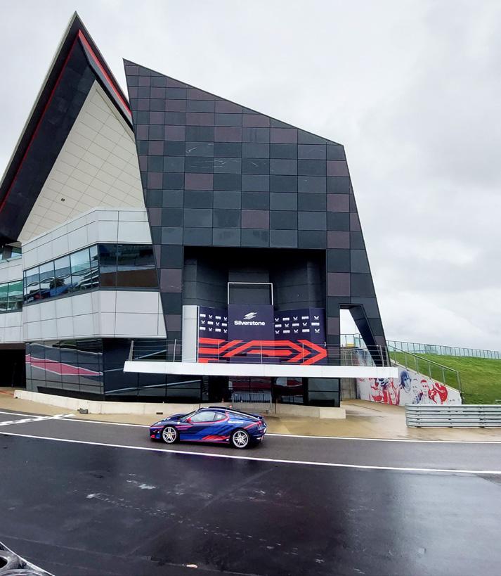
1985–2025 Celebrating 40 Years of


