
Journal of the Engineering Integrity Society
ENGINEERING INTEGRITY
March 2021 | Issue No. 50
TECHNICAL PAPER:
Low Filling Ratio Acoustic Space-Filling Curve Metamaterials for Jet Engine Inlets


ALSO INSIDE:
FATIGUE 2021, DOWNING COLLEGE, CAMBRIDGE
29 – 31 MARCH 2021
INSTRUMENTATION, ANALYSIS & TESTING EXHIBITION

SILVERSTONE, 14 SEPTEMBER 2021
www.e-i-s.org.uk


EV & HYBRID BATTERIES COMPONENT LIFECYCLE DURABILITY & NVH INNOVATIVE VIBRATION TESTING SOLUTIONS FOR: ROAD SIMULATION A member of the sales@dataphysics.com | dataphysics.com Dynamic Signal Analyzers Vibration Controllers Power Amplifiers Electrodynamic Shakers Service & Support Applications Experts
FATIGUE 2021
29 - 31 March 2021

KEYNOTES
Professor Robert Akid - Manchester University
Professor Filippo Berto - Norwegian University of Science and Technology

Professor Youshi Hong - Chinese Academy of Sciences
Professor Roderick Smith - Imperial College, London
3
& On-demand
Online
www.fatigue2021.com www.e-i-s.org.uk +44 (0)1623 884225 info@e-i-s.org.uk www.fatigue2021.com Booking now open PROVISIONAL PROGRAMME RELEASED
2021
FATIGUE
Instrumentation, Analysis & Testing Exhibition

Silverstone Wing, Silverstone Race Circuit


14 September 2021, 10am-4pm
• 60 exhibitors from aerospace, automotive, motorsport, rail, off-highway, mechanical handling, civil engineering, industrial and power generation industries. The exhibitors offer a wide variety of modern instrumentation, measuring and modelling technologies


• Free Entrance to Exhibition and Mini Seminars

• Free Car Parking
• Complimentary Refreshments
To complement the exhibition there will be a number of Mini Seminars.
To pre-register: info@e-i-s.org.uk | www.e-i-s.org.uk

ENGINEERING INTEGRITY SOCIETY
Co-sponsored by:
If you would like to receive this journal electronically, please contact the Marketing & Events Manager:
Contents: March 2021 Index to Advertisements ................................................................................... 5 Editorial .................................................................................................................... 7 Diary of Events....................................................................................................... 7 Obituary: Robin Anderson 8 Young Engineers 9 Technical Paper: Low Filling Ratio Acoustic Space-Filling Curve Metamaterials for Jet Engine Inlets ............................................................. 10 News from British Standards .......................................................................... 21 Inspiring the Next Generation ....................................................................... 22 Fatigue 2021 ......................................................................................................... 23 News from the Tipper Group 27 Engineering in a Post-Pandemic World 28 Industry News ...................................................................................................... 30 Software Verification ......................................................................................... 32 News from Institution of Mechanical Engineers ..................................... 35 University of Wolverhampton Racing ......................................................... 36 Product News....................................................................................................... 38 News from the Women’s Engineering Society 40 Group News 41 Corporate Members .......................................................................................... 42 Committee Members ........................................................................................ 43 Corporate Member Profiles ............................................................................ 45
info@e-i-s.org.uk INDEX TO ADVERTISEMENTS CaTs3 / Zwick 47 Data Physics........................ 2 EIS ........................................... 3 HEAD acoustics ............... 34 Micro-Epsilon ................... 37 M&P International .......... 48 Sensor Technology ......... 21
HONORARY EDITOR
Dr Spencer Jeffs
E-mail: s.p.jeffs@swansea.ac.uk
MANAGING EDITOR
Rochelle Stanley
Tel. +44 (0)7979 270998
E-mail: managingeditor@e-i-s.org.uk
MARKETING & EVENTS MANAGER
Sara Atkin
Engineering Integrity Society
6 Brickyard Lane, Farnsfield, Notts., NG22 8JS
Tel: +44 (0)1623 884225
E-mail: info@e-i-s.org.uk
WWW: www.e-i-s.org.uk
EDITORIAL POLICY
Engineering Integrity contains various items of information of interest to, or directly generated by, the Engineering Integrity Society. The items of information can be approximately subdivided into three general categories: technical papers, topical discussion pieces and news items. The items labelled in the journal as technical papers are peer reviewed by a minimum of two reviewers in the normal manner of academic journals, following a standard protocol. The items of information labelled as topical discussions and the news items have been reviewed by the journal editorial staff and found to conform to the legal and professional standards of the Engineering Integrity Society.
COPYRIGHT
Copyright of the technical papers included in this issue is held by the Engineering Integrity Society unless otherwise stated.
Photographic contributions for the front cover are welcomed.
ISSN 1365-4101/2021
The Engineering Integrity Society (EIS) Incorporated under the Companies Act 1985.
Registered No. 1959979
Registered Office: c/o Hollis & Co., 35 Wilkinson Street, Sheffield S10 2GB
Charity No: 327121
ADVERTISING RATES & DATA
‘Engineering Integrity’ is published twice a year
Black and White
1 insert 2 Inserts
Full Page £255 £460 annual
Half Page £158 £285 annual
Quarter Page £92 £175 annual
Full Colour
1 insert 2 Inserts
Full Page £445 £800 annual
Half Page £278 £500 annual
Quarter Page £160 £290 annual
Full Page 297mm (depth) x 210mm (width) and 3mm bleed
Half Page 255mm (depth) x 86mm (width) or 125mm (depth) x 180mm (width)

Quarter Page 125mm (depth) x 86mm (width)
Space is limited so place your order soon to avoid disappointment.
A copy of the latest issue of ‘Engineering Integrity’ is published on the website and includes all advertisements.
Loose Inserts £150 per A4 sheet (up to 160 gsm)
PRINCIPAL ACTIVITY OF THE ENGINEERING INTEGRITY SOCIETY
The principal activity of the Engineering Integrity Society is the arrangement of conferences, seminars, exhibitions and workshops to advance the education of persons working in the field of engineering. This is achieved by providing a forum for the interchange of ideas and information on engineering practice. The Society is particularly committed to promoting projects which support professional development and attract young people into the profession.
‘Engineering Integrity’, the Journal of the Engineering Integrity Society is published twice a year.
‘Engineering Integrity’ is lodged with the Agency for the Legal Deposit Libraries on behalf of the Bodleian Library Oxford University, the Cambridge University Library, National Library of Scotland, National Library of Wales and Trinity College Dublin.
6
Dr Spencer Jeffs, Honorary Editor
events in early 2021, but with local and international travel restrictions in place it is of course not safe or recommended to do so yet. As such, Fatigue 2021, the 8th conference in the series will be held online and ondemand from 29 to 31 March. I do hope many of you will join the event which will explore the latest developments in the field, with Keynotes being delivered from worldleading experts.
In November, the UK committed to ban sales of new petrol and diesel cars from 2030 under its ten-point plan for a ‘green industrial revolution’. Offshore wind, hydrogen, nuclear, electric vehicles, jet zero and greener maritime make up a significant portion of these points. Many of the points outlined are pertinent to the EIS community and will no doubt pose significant challenges and opportunities alike.
Sadly, we lead this edition with an obituary for Dr Robin Anderson who passed away in July. Our condolences go to his family and friends.
The COVID-19 global pandemic continues, and the winter months have seen a surge in both cases and deaths in the UK with highly transmissible strains being detected, health services stretched to the brink and lockdown restrictions enforced. The global picture is largely similar; at the time of writing over 100 million cases have been officially recorded along with nearing 2.5 million deaths according to John Hopkins University database – staggering and tragic numbers.
Nonetheless, some countries have largely succeeded against COVID-19, the most prominent example being New Zealand which has seen less than 30 deaths and thousands in sports stadiums since June. There is potentially light at the end of the tunnel with vaccine development occurring at record speeds, be they mRNA, viral vector, or protein-based, and a number of these now approved vaccinations being rolled out and administered across populations.
I wrote in September that we had hoped for non-virtual
Diary of Events
The technical article in this issue investigates metamaterials for jet engine inlets, a long-term goal of which is aircraft noise control. Aircraft noise can disturb sleep, cause community annoyance, increase health risks to those living in the vicinity of airports and often constrains air traffic growth. Therefore, implementing noise reduction innovations is expected to result in significant benefits to the industry.
Industry news reports the use of machine learning technology in the field of additive manufacturing, a technology that offers huge potential in areas such as process optimisation, automation, design & simulation and data management, although, any biases or limitations need to be seriously considered.
For the majority of university students, certainly those studying the in UK, the world of online learning continues, with students largely recommended not to return to campuses and rent rebates rightly being given. Missing out on the full experience of university for any time period is not a nice thought and I commend their resilience in adapting to online learning. Personally, I look forward to the day we are back in lecture theatres or practical lab classes as opposed to being faced with a majority of muted name tiles.
Stay safe.
Spencer Jeffs7
Editorial
Welcome to the Engineering Integrity journal spring 2021 issue.
Fatigue 2021 | Downing College, Cambridge | 29 – 31 March 2021 EIS Committee Meetings | Online | June 2021 Instrumentation, Analysis and Testing Exhibition Silverstone Race Circuit | 14 September 2021 Young Engineers Seminars | Various dates in 2021 Generation & Storage of Renewable Energy: Durability & Reliability | Date TBC
OBITUARY
Robin Anderson
1951–2020
We are sad to report that on 24th July 2020, our friend and colleague, Dr Robin Anderson lost his fight against leukaemia. We will miss him and our thoughts are with his family.

Many will remember him for contributions to EIS events over many years and could be forgiven for assuming he was British but was in fact born in 1951 in South Africa. He first came to the UK as a teenager and flew back and forth between home and school over the African continent in what we would now consider early jet airliners, which explains his interest in 'planes and in particular reliability and performance of jet engines in hot and high conditions. Robin gained a place at the University of Cambridge in 1970, graduating in 1974 with a materials science MA; anyone referring to him as a metallurgist would be swiftly corrected with a wry smile. Soon after, he studied at the University of Sheffield for an M.Met. in Metallurgy, graduating in 1977. He then returned to South Africa to work on his PhD in "Fracture in Aluminium Alloys" at University of the Witwatersrand graduating in 1983. He still found time to travel back and forth to the UK and in 1980, at a party in London, met another PhD student (from the London school of hygiene and tropical medicine) Moira, his future wife.
From 1984 to 1986 he returned to Sheffield where he worked as a post-doc research fellow on the measurement of Fatigue Thresholds in Structural Steel used in the UK Coal-mining Industry on behalf of the UK Health and Safety executive (HSE). It was there that he also made some lifelong friendships with colleagues with whom he spent time socially and technically, and connected him to the nCode world as a customer initially. In those days, due to South African roots, he had to report to the local Sheffield police station annually to register as "an alien", a story he liked to tell as it made him smile knowing full well that his public-school accent suggested he was more British than the bobby on the front desk! Robin then left academia for industry, putting his wealth of knowledge to good use. From 1986 to 1997, he worked at the Lucas Group (later TRW) research centre with the unforgettable Dog Kennel Lane address. He worked on materials development projects and also failure investigations for the Lucas operating companies, spanning both aerospace and automotive divisions. These days composites are common place and different industries just assume a short or long fibre type and polymer matrix, which can make for initially confusing discussions.
Robin, being a material scientist, would never miss the opportunity to ask if this composite
was wood or metal. At Lucas he'd worked on developing metal matrix composites for automotive use. Having used nCode's software in his Lucas days, he was drawn to joining the nCode team. In 1997, Robin left the big PLC for a small Sheffield company, nCode International (later to become HBM nCode, part of Spectris PLC), working on materials and fatigue related projects for customers and internal research work. One such example, spanning many years, was Thermo Mechanical Fatigue to help meet the ever rising temperatures of turbocharged engines. His broad knowledge of materials was widely recognised and appreciated as was also his "joie de vivre" which in Robin's case also reflected into his "joie de la technologie"! He could often be found bending over cars, including his beloved Jag S type and in earlier years, his Alfasud, and other engineering systems both old and new discussing them in detail and getting his hands dirty literally! Robin loved talking with people and his relaxed and friendly manner made him a very popular presenter and mentor to young engineers. He had a gift for explaining complicated phenomena in a simple and structured way. His wide experience of materials science always provided a rich source for witty and instructive anecdotes.
Robin is most fondly remembered by his nCode friends for his warmth and enthusiasm, especially when discussing new material testing methods over a panini and cappuccino, which he's always order with "an extra shot please". We frequently joked that no problem would be insurmountable when Robin was sufficiently fuelled with coffee and Coca-Cola. Many EIS members are involved in measuring the operating conditions of products and reproducing these in the lab. Others strive to simulate and predict the performance before testing. One vital input is materials performance, which Robin was always pleased to help with, offering both quantitative and qualitative advice, whilst reminding us of the need to test the material in question. Robin retired in 2016, looking forward to life beyond work with his family of which he was obviously very proud: Moira and their sons Hamish and Duncan. Even in his retirement he could not put down the materials pen, working as a freelance engineering consultant with past colleagues!
For sure, he will be missed by all of us who knew him and enjoyed his company both professionally and socially. One of his retirement projects was to restore the family Jaguar 420 to working order and hand the keys Hamish to drive away.
8
One of the key challenges we faced during 2020 was how to support our Young Engineers during a global pandemic, which has necessitated a change in approach to learning. The group had discussed the value of running webinars alongside our face-to-face seminars for some time and the current crisis has proved to be the right time to introduce this additional offering.
Our first webinar was delivered back in July when David Ensor (formally of HORIBA MIRA) kindly agreed to be our inaugural presenter with ‘Road Load Data Collection & Analysis - are you forgetting the basics?’ As this was our first foray into delivering virtually, we were relieved to only have a couple of minor technical hitches, but these did not detract from David’s informative and interesting talk. There was a steady stream of questions from the delegates which generated some excellent points for discussion. This resulted in the webinar continuing well over the allotted hour but almost all attendees remained on the call to the end. This is of course testament to David’s skills as a presenter and endorses our aim of sharing the knowledge and skills of experienced engineers with the next generation.
Our second webinar looked at the ‘Myth of Accuracy’ and we were grateful that Damian Harty, who had just returned to the UK from America, was willing to present during his enforced isolation period. The Myth of Accuracy was originally the focus of a paper in this journal (vol 9) back in 2001 and was subsequently presented at the very first Young Engineers meeting we held at the University of Birmingham in 2012. During his presentation Damian looked at the commonly held view that usefulness of a predictive model is directly related to its accuracy as measured in the real world. His argument was that there is a time when sufficient accuracy is optimum and he suggested an approach which encourages discernment of optimum accuracy by all involved in the process.
In a move away from our traditional technical seminars, our third and fourth webinars in the run up to Christmas focused on soft skills training. This is an area not always accessible to young engineers despite its value and importance in career and personal development and we regularly receive requests to address this gap. We were fortunate to collaborate with experienced and award-winning coach Dyfrig Jenkins of YOU.Development to bring ‘Feedback that Works’ and ‘Improving Performance through Effective Coaching’ to our audience. Dyfrig was keen to make these sessions interactive, encouraging delegates to present their own views and experiences, which encouraged greater participation. This enabled those attending to apply the presented concepts to their
own personal situations, and Dyfrig left plenty of time for questions and discussion to further the audience’s understanding and development.

We started 2021 with a webinar on a topic which is very much at the forefront of current research. ‘Destination Zero: Sustainability of the electrified vehicle whole life cycle’ looked at two important areas. Our first presenter, Dyrr Ardash of Williams Advanced Engineering, identified a number of factors along the journey from production to end-of life and highlighted the industrial development and implementation of technologies and processes towards more sustainable mobility solutions. Also discussed was the approach and requirement issues that car manufacturers should consider during the process of vehicle design and development. Our second presenter, Jonathan Saul of Millbrook, then focused on the safety concerns that the automotive industry is having to overcome to certify their new electrified vehicles. Both presentations prompted numerous questions from the audience and the webinar saw our largest audience to date with over 80 attendees.
As it is still unclear when physical events will be allowed to resume we plan to continue our series of webinars during the coming months. We are fortunate to have wide support from industry and access to presenters who cover a range of topics and technical areas. As ever, we welcome your input and if there are subjects you feel it would be beneficial to include please let us know. Whilst the webinars are primarily aimed at those at the start of their engineering careers they are equally applicable to all levels and we welcome attendance from anyone who would benefit.
9
Latest News
Young Engineers
Damian Harty’s original paper ‘The Myth of Accuracy’ from volume 9 of Engineering Integrity is available as a PDF by emailing info@e-i-s.org.uk.
Technical Paper:
Low Filling Ratio Acoustic Space-Filling Curve Metamaterials for Jet Engine Inlets
JN Glover | PhD Student, Department of Aeronautical and Automotive Engineering, Loughborough University, UK DJ O’Boy | Senior Lecturer in Structural Dynamics, Department of Aeronautical and Automotive Engineering, Loughborough University, UK Corresponding Author: J.Glover2@lboro.ac.uk1. Introduction
As pressure grows for aircraft noise control, from organisations like the Advisory Council for Aircraft Research and Innovation in Europe (ACARE) there is an increased need for innovation in Aeroacoustic attenuation. The nature of noise means that a targeted approach to attenuation is far more effective in achieving overall observable noise reductions. Therefore, this project focuses on the dominant noise source, the engine, which accounts for approximately 68% at approach and at take-off approximately 98% of the total aircraft noise [1] (percentage of total logarithmic dB output). Any solution needs to cope with extreme operating conditions and low frequency noise not commonly controlled by traditional methods, due to the long wavelengths involved. This paper introduces innovative metamaterial acoustic liners as solutions for the jet engine inlet and builds on the work by Glover and O’Boy 2020 [2].
Metamaterials demonstrate a huge resource for acoustic control, whether passively in coiling-up, Helmholtz resonator-like or membrane structured, as reviewed in the paper by Assouar et al [3], or actively with piezoelectric, mechanical or electric and magnetic biasing as discussed in “A Review of Tunable Acoustic Metamaterials” [4]. For this project, the metamaterials studied are space-filling curves (SFCs) defined by their sub-wavelength structural, curled cross sections. They are classed as a passive absorber acoustic liner. The SFC provides an elongated coiled propagation path able to attenuate much lower frequencies then an undivided cavity of the same dimensions. They are not governed by traditional bulk modulus and density characteristics. SFCs offer subwavelength low-frequency attenuation with the potential to provide a lightweight, thin, highperformance acoustic liner [3].
The present paper contains a comparison of some of the most promising low filling ratio metamaterial designs which utilise space-filling curves. It evaluates the liners in terms of the fundamental theory of the design and a discussion of the reflection and absorption characteristics. The design of the original inspiration for this method are provided, then the paper discusses computer simulation and experimental testing to compare the different designs based on impedance tube measurements. Conclusions are also made as to the future application for aeroacoustics with particular focus on the engine inlet.
2. Acoustic Liners
Typical acoustic liners for a commercial jet engine use the principle of a Helmholtz resonator (HR) where a mass of air oscillates on a spring of air trapped in a volume. HR implementations are cheap passive devices, are relatively lightweight and effective for one dominant frequency and most importantly, need a large depth to attenuate low frequencies. The issue of low frequency attenuation is due to the mass law. The effect is, essentially, the lower the desired attenuation frequency, the larger the liner depth needs to be [5] (and for the purposes of this paper the frequency range of interest is 200–2000Hz). By targeting one dominant frequency, any other frequencies are not substantially affected, and the same weight penalty remains. Hence, the choice of critical frequency and the potential for multiple frequency targeting is paramount.
The liners are proposed to control the dominant frequencies of jet engines, typically below 1000Hz, with the lowest at approximately 630Hz by Khardi [6]. Moreover, the industrial trend towards ultra-high bypass engines means there is a potential increase in bypass ratio from 8 to 15 [7]. Since ultra-high bypass fans result in an increase in weight and potential drag, it is predicted that there will be a subsequent reduction in the thickness of the outer casing, meaning that any soundproofing contained within needs to become thinner [7].
Therefore, in this paper the depth of the liners is tightly controlled below 50mm, the lower end of typical current liner depth. A successful metamaterial acoustic liner would show a reduced weight and thickness compared to a traditional HR liner, i.e., a low filling ratio design (the filling ratio is the proportion of wall volume to open air volume). By utilising the sub-wavelength attenuation and high reflective nature of the SFC, a significant sound reduction can be achieved with a relatively low weight liner. In addition, a 2020 paper by Glover and O’Boy concludes that low filling ratio SFCs generate a higher mean absorption coefficient when tested in head on flow conditions [2].
2.1 The Helmholtz Resonator
Traditional Helmholtz resonators (HR) are used to control steady, simple, harmonic sound at a narrow frequency range. The main advantages of this resonator is its simplicity, although careful tuning is required
10
ENGINEERING INTEGRITY, VOLUME 50, MARCH 2021, pp.10–20. ISSN 1365-4101/2021
for effective noise attenuation [8]. The HR works as an acoustic stopband filter with the action of the volume of air in the cavity emulating a mass spring system [8]. However, this causes an undesirable back pressure, which has a detrimental effect on the efficiency and performance of the engine. The limited narrow band can be improved with a range of tuned HRs, but this has a proportional increase in back pressure [5]. If frequency bands could be filtered out through an alternative method, such as multi-resonant scattering, there would be a far smaller effect on engine efficiency which could be a designed in characteristics of metamaterial liners.
For the purposes of comparison in this paper, a baseline acoustic liner was designed using a hexagonal 610Hz

with a sub-wavelength curled wave path creating a maze-like pattern (Figure 2-3). SFCs were developed from a purely mathematical problem where a line passes through every cell element of a grid, so that every cell is visited exactly once. They have been proposed in acoustics for a decade or so due to their potential ultrathin, low frequency, broadband attenuation overcoming the drawbacks of traditional HRs.
In this paper, three designs are investigated, termed horn, meander and spider. For the purposes of this project, the investigated SFC designs are divided into two categories: curl-up (horn and meander), where there is a single path through a unit; and maze-like (spider), where there are multiple propagation directions within the unit. To understand the advantages of metamaterials as a noise control method there needs to be an appreciation of the physical attenuation mechanisms.
The primary physical mechanism of noise reduction in both types is an extended path length compared to unit depth, which enables subwavelength attenuation. Different designs can offer multiple propagation paths, directions and scattering. For curl-up SFCs (Figure 2-6), Wang et al [9] have proposed an equivalent model which applies HR, and quarter wavelength (QWR) tube theory, to a ranging transfer matrix that defines the SFC peak frequency. The transfer matrix establishes a relationship between the acoustic pressure and volume velocities in two defined regions.
Equation 2-1 shows the two regions. The first is a straight region, which is the straightened coiling path (denoted I) equated to a resonator neck and the second is a cavity region, which would be the designated voids (denoted II). When region 1 tends to zero the HR theory alone applies and when region 2 tends to zero, the quarter
tuned HR (Figure 2-1 and Figure 2-2), see formula in [7]. This design was also used in the 2020 paper [2]. This was chosen to compromise between industry-standard design, the working frequency range of the experimental impedance tube and available 3D printing capabilities allowing rapid prototyping and experimental verification of the trends. The hexagonal HR liner was a benchmark of success criteria for the SFC liners. Thus, a good liner would show a better absorption coefficient at a wider frequency range and ideally at a lower weight.
The additional characteristics of a typical sandwich configuration was also applied to the SFCs for the following three reasons: 1) The two-microphone impedance setup does not allow for the grazing configuration and the tube was designed to record head-on resonance for sandwich liners. 2) A sandwich configuration is the current standard for soundproofing thus can be considered commercial. 3) The additional resonant conditions are predicted to improve absorption coefficients for the SFC samples.
2.2 Space-Filling Curves
Space-filling curve (SFC) metamaterials are designed

11
Figure 2-1: Helmholtz Resonator 610Hz.
Figure 2-2: Helmholtz Resonator 610Hz unit cell.
Equation 2-1: Relationship between the acoustic pressure and volume velocities at the neck of the tube and the end of the cavity [9].
wavelength theory alone applies. The curl-up SFCs studied in this project (horn, meander and zigzag from a previously published paper) all build on classical theory. The resonant frequency for the same volume of HR unit can be reduced by making use of curling channels to reduce the space required: QWR uses Equation 2-2, HR uses Equation 2-3 and Fabry–Pérot resonance (FP) using Equation 2-4. The use of voids, framing, right-angle bends and many other flow path features causes the SFC resonance to deviate from the basic theory, which is why models such as the equivalent model transfer matrix are used [9]. Although this approximation works well for curled-up designs, it is less accurate for the maze-like SFCs such as the spider.
The maze-like designs are better understood using Mie resonant theory as they offer multiple propagation directions and a high reflective index. Mie resonance is commonly defined in light rather than sound, but it still applies when the size of the scattering sphere is comparable to the wavelength. Mie-resonance particles have a high refractive index relative to the background medium. They are initiated in this case

Equation 2-2: QWR resonant frequency.

Equation 2-3: HR resonant frequency.

Equation 2-4: FP resonant frequency.


due to the ultraslow relative propagation through the flow path compared to the in-space dimensions (Figure 2-4) [10]. These liners often benefit from multiple resonances instigated at low frequency due to the high contrast of sound speed with the isotropic resonant
12
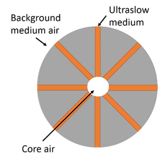
Figure 2-4: Ultra slow fluid medium representation of spider liner.
Figure 2-3: Spider SFC liner model.
frequency shown in Equation 2-5. The proposed spider maze-like metamaterial is described as being an ultraslow medium demonstrating the high contrast in wave speed needed to observe Mie resonance [11].

It was predicted that the low filling ratio (<20%) characteristic of these three designs could result in an overall reduction in weight whilst maintaining or improving noise attenuation in a broadband low frequency range.

This design termed horn was chosen as it was capable of phase-amplitude modulation beyond conventional space-coiling structures, with a potential for sound focusing and acoustic beam splitting. The sample seen in Figure 2-6 and unit sizing (Figure 2-7) was inspired by Ghaffarivardavagh et al. [13]. A custom 1kHz design with 1% transmission coefficient.
The test liner was tessellated (Figure 2-6) to cover the whole 95mm diameter space available in the test rig (See Figure 3-1). The filling ratio of horn was 9.4%, therefore is considered very low and the sample was the lightest of the 3 SFCs. It is the only liner lighter than the HR baseline (Table 4 1). The Ghaffarivardavagh et al. [13] data was presented only as transmission coefficient whereas the two-microphone impedance method only establishes reflection and absorption coefficient. For comparison, the peak transmission 1000Hz was taken as the peak absorption frequency although, as discussed in section 2.2.3, this may not be an accurate representation.
2.2.2. Meander
2.2.1. Horn
The first acoustic liner design investigated was proposed by Ghaffarivardavagh et al. [13] named ‘’Hornlike space-coiling’’. This design was an advancement of the zig-zag configuration based on Liang and Li [14] adding a gradual change in channel width allowing for impedance matching. The sample presented by Ghaffarivardavagh et al. was tested computationally with the Transfer Matrix Method based on computer modelling, using the finite element analysis software COMSOL. Then it was experimentally validated as a large rectangular sample with a 40cm measurement region much larger than the sample in Figure 2-6 which is 95mm in diameter.
The “Coiling-Up Space Metasurfaces” was developed by Chen et al. and is the second design under investigation in this paper [15]. This design is an acoustic metasurface with a perforated top plate and co-planer spiral tubes in coiling channels. It was tested using simulation in COMSOL and validated with an impedance tube method. Unlike the horn or spider liners or any of the phase 1 samples (see Glover and O’Boy [2]) this was the only SFC design optimised with a perforated plate. This was a key factor in its inclusion in the study as a perforated plate is the standard for traditional liner constructions. Additionally, in high flow speed and long run time regions such as a jet engine inlet, foreign object debris is a substantial concern, thus the use of perforated plates

13
Equation 2-5: Isotropic Mie resonant frequency [12].
Figure 2-6: Horn SFC liner model.
Figure 2-7: Horn liner unit.
has been the established prevention method.
The design shown in Figure 2 8 was developed based on the work by Chen et al. [15]. The channels act as nesting dampeners producing dual band resonance (in this case 256Hz and 350Hz). The thickness of the metasurface is smaller than 1/50 of the resonant frequency wavelength and set in the reproduced model as 20mm. This design is chosen as it has the lowest predicted resonant frequency and a low filling ratio of 14%. The performance of the design is particularly interesting because the predicted values are so close to the lower limit of the working frequency range, therefore open to experimental error.


2.2.3. Spider
The “Spider Web-Structured Labyrinthine Acoustic Metamaterials” was developed by Krushynska et al. and is the final design under investigation [11]. This design configuration consists of a square external frame and a circular maze-like path divided into eight independent circular-shaped channels connected at the centre. As a result of the need for consistency between the designs,
the sample is circular and unframed (Figure 2-9). However, the advantages of framing will be studied in future work.
Krushynska et al. tested the design using simulation in COMSOL only and demonstrated consistent low transmission for a frequency range 0–2000Hz. Unlike the horn or meander designs, the spider is classified as a maze-like SFC meaning there are multiple propagation routes rather than a singular flow direction. This design is also very difficult to predict through a numerical theory due to the presence of Mie scattering, which is why the origin paper’s use of simulation is vital in predicting the acoustic performance.

The design shown in Figure 2-9 was inspired by the garden spider Araneus diadematus. It was chosen due to its low filling ratio of 10%, which is much smaller than that of the maze-like SFC studied in phase 1: 17% for hexagonal and 35% for labyrinthine [2]. In addition, Krushynska et al. concluded the spider SFC is highly tuneable with activation or elimination of subwavelength band gaps and negative group-velocity modes can be refined by increasing/decreasing the edge cavity dimensions. Like the horn work, this design is presented via transmission rather than absorption thus the peak values may not consistently align. Absorption coefficient has two different formulas based on whether transmission is possible within the experimental setup (Equation 2-6 and Equation 2-7).
Generally, absorption and reflection coefficients are mirror plots, but the transmission may not follow the same trend. As a result, the accuracy of this design recreation, particularly in terms of full-range low transmission, will not be known fully until the fourmicrophone impedance test stage, which is not part of this paper.

14
Figure 2-9: Spider liner unit.
Figure 2-8: Meander liner unit.
Equation 2-6: Absorption coefficient for anechoic termination.
Equation 2-7: Absorption coefficient for rigid termination.

15
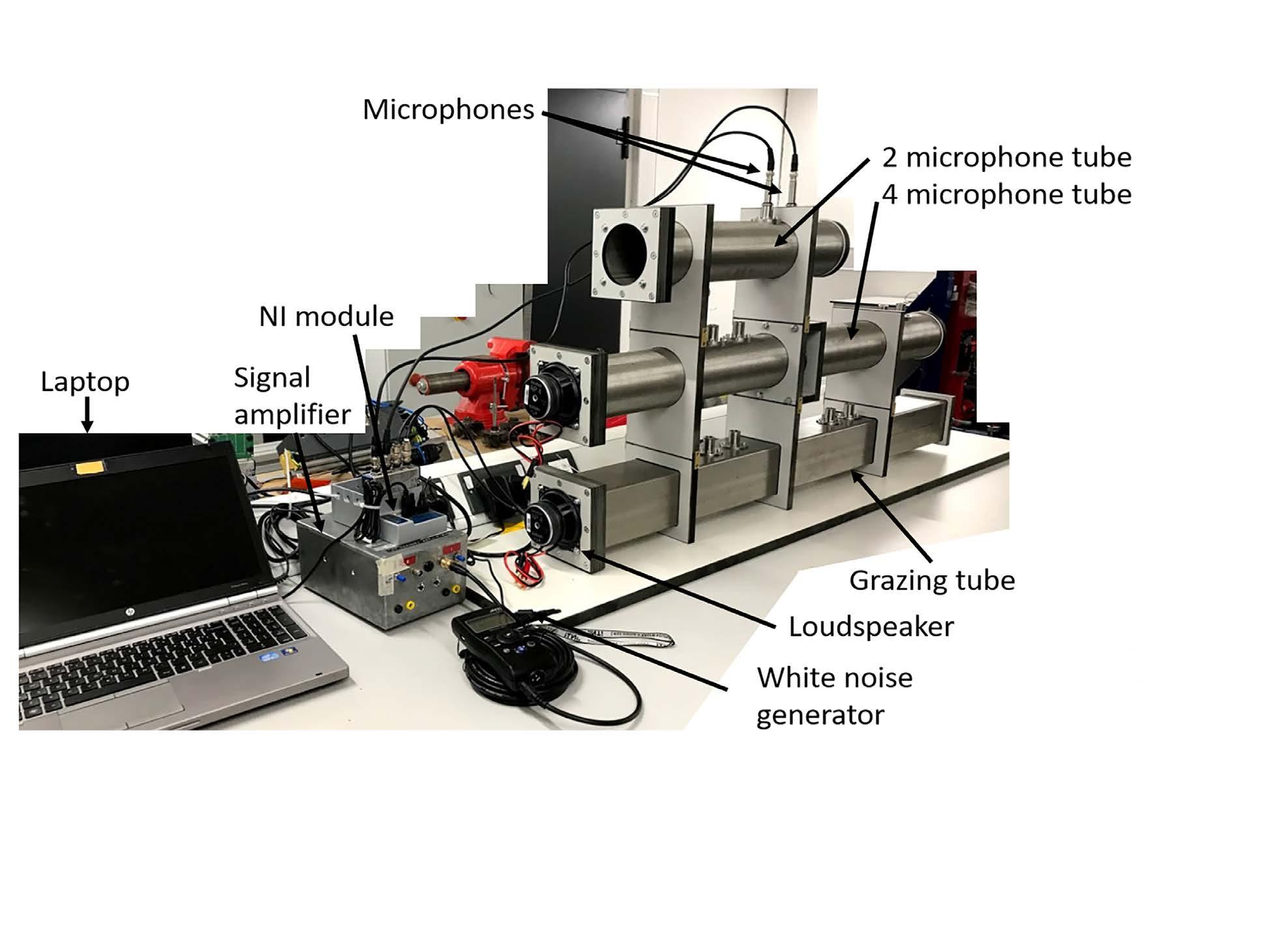
Figure 3-1: Photograph of the experimental rig.
Figure 3-2: Two-microphone impedance tube.
3. Impedance Tube Rig
3.1. Impedance tube theory


A two-microphone impedance tube (Figure 3-1) was designed and built to accurately measure sound reflection and absorption coefficients according to ISO10534-2 [16]. The basic principle of the tube is that a plane wave is generated by a sound source and measurements of acoustic pressure are taken at fixed locations depending on the number of microphones. The reflection or absorption through the sample generates a standing wave that can be measured by the microphones.
A white noise source is used with no external flow applied. Calculations are carried out using a complex transfer function to determine the normal incidence absorption and impedance ratios of the acoustic material (Equation 3-1, Equation 3-2). The usable frequency range depends
on the width of the tube and the spacing between the microphones (Figure 3-2) [16]. In this case, the diameter of 100mm and length 500mm give a working range of 200–2000Hz. The origin papers are not all tested in the same standardised method or flow conditions therefore this paper experimental work can be uniquely compared.


4. Experimental Analysis of Liners
4.1. Methodology
The experimental analysis determined the reflection and absorption coefficients of each liner by frequency and as a mean value. The data was then compared between the liners and the simulation results in the comparison papers. The liner samples were designed such that each core liner has a diameter of 95mm and a rigid backplate of 2.5mm. The core height is 15 mm for the horn SFC is based on the core height for the 610 Hz resonant HR baseline. As the meander and spider design stated their core height it was maintained in this case at 17 mm and 20mm. An additional variable of three designed top plates of thickness 2.5 mm and no top plate options were investigated.
Each liner was tested with no top plate, the HRTP (Figure 4-1) and a many-hole top plate. The meander used MTP
16
Figure 4-1: Helmholtz resonator top plate.
Figure 4-2: Multiple hole top plate.
Figure 4-3: Meander top plate.
Equation 3-1: Transfer matrix two-microphone impedance tube.
(Figure 4-3) rather than MHTP (Figure 4 2) to match the perforated plate used in the origin paper’s experimental work. All components were printed using a Connex 260 and utilised a ‘’Vero White’’ plastic. The experimental analysis of all four liners followed the ISO10534-2 [16] protocol for a two-microphone impedance tube. The weights can be found in Table 4-1.


17
LINERS WEIGHT (g) TOP PLATES WEIGHT (g) Helmholtz Resonator 50 Helmholtz Resonator 21 Meander 60 Many-hole 18 Horn 47 Meander TP 21 Spider 59
Figure 4-4: Absorption coefficient values for all tested liners.
Figure 4-5: Mean reflection and absorption coefficient values.
Table 4-1: Acoustic liner and top plate weights.
4.2. Results
The absorption coefficient relationship to frequency is presented in Figure 4-4. There are common trends between all liners: the use of a top-plate has a significant increase on the overall absorption coefficient; the non-top-plate configuration absorption values are consistent for all liners and there is no strong indication of the effect of the designed flow path without a top plate. An interesting deviation from the expected is the horn with MHTP which, unlike the other two SFCs and liner theory, does not show an increase in peak frequency when more perforations are introduced. The theoretical peak increase as predicted by the work of Bies and Handen [17].
Conversely with MHTP the horn has a dual peak at 790 and 1590Hz compared to the HRTP 1430Hz. This change is assigned to an increase in the peak frequency associated with the resonant HR mechanism of the liner and the 790Hz peak aligns with an analytical study of the Fabry–Pérot resonance peak (Equation 2-4). For all designs, Figure 4-4 does not show peak frequencies that align closely with the origin paper. This is because there is a distinct difference between the subwavelength attenuation, transmission properties and resonance attenuation. This difference will be captured by the progression work of the project summarising head-on, grazing and transmissive characteristics of SFCs for acoustic liners.
The peak frequencies are much broader than predicted and with additional multiple peaks. The baseline HR has a peak resonance of 580Hz, which is within the printing tolerance resonance range 570 to 650 Hz (this also shows some of the issues with generating exact tolerances for resonators using rapid prototyping manufacturing methods). There is an additional peak at 1600Hz, which is anticipated to be due to structural resonances caused by the outer edges of the test liner. As shown in Figure 2-1, smaller units are tessellated to fill the 95mm diameter or cropped (Figure 2-8). The structural resonances can be reduced by framing, but design factors such as this are removed from this experimental phase to create consistency. The free walls are excited by the flow through the top plate and around the edge of the tube causing additional dominant peaks. This theory was tested in later project work when additional design factors were implemented. Furthermore, the core and top plate are only temporally fixed rather than bonded due to limited printing resources, which can lead to flow creep and coupling between units. The result of these factors is a non-ideal resonant plot, but they are more consistent with working conditions where samples are cut to fit or degrade over time, thus an understanding of the impact is valuable.
4.2.1. Mean reflection and absorption coefficients

18
Figure 4-5 displays the mean acoustic coefficient
Figure 4-6: Absorption coefficient frequency peak comparison of computational and experimental data.
values for all sample configurations. For all SFCs and the HR, the introduction of a top plate increases the absorption coefficient significantly. It is also generally true that increasing the number of holes in the top plate increases the overall absorption but shifts the resonant frequency to higher values. This relationship is not linear; MTP has 2 holes compared to the 19 of HRTP which results in a 0.11 mean absorption increase, whereas HRTP to MHTP with 69 holes results in an average of a 0.047 coefficient increase, and this observation aligns with the perforated plate work of Bies and Handen [17].
The aim of this research is to propose an SFC acoustic liner that is comparable or better than the baseline HR. The success criteria are an increase in absorption coefficient at targeted low frequencies, at a reduced depth and weight. No SFC designs outperformed the traditional HR in absorption coefficient in these flow conditions. The best performing SFC configuration is the horn at a 3g reduction in weight. The SFCs are developed in grazing flow simulation to better represent operating conditions, but the two-microphone impedance tube was developed around the traditional HR liner, thus it may not be a surprise that the HR performs best. Nonetheless the broadband attenuation offered by the SFC at a range of frequencies in the 200–2000Hz window shows the promise they have for broader low frequency noise applications. In addition, with continued research and tuning they could be well matched to the noise profile described by Khardi [6].
4.2.2. Resonant peak
Figure 4-6 illustrates the comparisons of experimental and simulation (determined from origin journals) resonant peaks. The experimental data points are sized according to absorption coefficient to capture the weight for acoustic significance. The simulation data points are all set to 1. This is due to the range of data presentation in the origin papers not enabling this weighting. Generally, the peak frequencies in the paper do not align with the experimental resonant peaks, indicating the grazing flow peak does not determine head-on peak value.
The meander had the closest test method in the origin paper to this body of work but as seen in Figure 4-6, the peak alignment was poor, even with the Chen et al.-defined MTP. The mitigations for this difference are the cropping of the design to fit the experimental tube and the lack of a framing around the core.
However, with an experimental peak of triple the expected, other parameters need to be considered. There may be experimental differences and there was little detail presented by Chen et al. other than that a two-microphone impedance tube was used. While input source amplitude and flow may differ, the material characteristic instead of flow path may dominate or the bespoke rig (Figure 3-1) may be insensitive so
close to the lower working frequency band. Factors such as this, and more, are why consistent controlled experimental comparison was needed for all liners.
A simple numerical study using QWR, HR and FP theory described in section 2.2 and Equation 2-2 to Equation 2-4 did show good agreement. Figure 4 6 shows the meander HRTP 11mm channel FP is 1240Hz, with QWR predicted as 621Hz. For meander HRTP, the 10mm channel FP is 1465Hz and QWR 730Hz. The MTP configuration does not align well with any of the classical theories. The HR is the closest, 1298Hz for the 11 mm channel, and 1123Hz for 10 mm.
It could be argued that the open channel paths as seen in Figure 4-3 would allow for an extended volume reducing the resonant frequency to near 905Hz or this value lies in between the FB, QWR and HR theory as indicated in the equivalent model transfer matrix (Equation 2-1), but regardless, the performance was at a much higher frequency range than expected.
The spider design was defined in its origin paper as having low transmission for the full 0–2000Hz range and although transmission is not inspected here, it was predicted that this trend for the whole working frequency range would be present. Therefore, the simulation data point for the spider are set at the extremes of the range.
Conversely, the spider did not show this characteristic, rather a promising multiple low-frequency peak with HRTP and a monopole for the MHTP configuration. The spider did not show the broadest attenuation, or the largest mean absorption coefficient as might have been expected. Yet, if the pattern is as tuneable as indicated by Krushynska et al. it could be optimised to the characteristic noise of an aircraft, thus this lowfilling ratio maze-like SFC will be refined in future work.
5. Conclusion
The frequency agreement between the simulation data presented in the papers and this comparison was generally poor, demonstrating the large variation in attenuation. Although the models could not be perfectly recreated, peaks were consistently at a higher frequency than predicted. The SFCs were chosen for their broadband and multiple resonant lowfrequency resonance, but this experimental work did not reliably show the multiple resonant characteristics being highly influenced by top plate configuration. This demonstrates it was essential to test liners in consistent conditions to capture a comparable acoustic performance.
The origin paper deviated in experimentation and simulation methods and this standard test itself is not reflective of industrial environments. The results also indicate the difficulty of primarily reaching low frequency attenuation as many off design parameters result in higher frequency attenuation. The absorption
19
performance of horn and spider liners showed the promise of SFCs, whether at a reduced weight and comparable mean absorption to HR or multiple lower frequency absorption, respectively.
6. Future Work
The vital progression for this work is multiple environment industry-standard impedance tube tests. By using two, four-microphone and grazing impedance tubes, the full acoustic profile of absorption, reflection, transmission coefficients and sound transmission loss is captured in head-on, transmissive, and grazing flow. This full profile solution is a unique approach in capturing the potential of SFC design in a comparable experimental basis.
The result is an ability to propose a prototype metamaterial liner adapting existing space-filling curves with flow path tuned to a low-frequency range specific to jet engine inlets as prescribed by work by Khardi [6].
References
[1] N. Pignier, “The impact of traffic noise on economy and environment: a short literature study,” Stockholm, 2015.
[2] J. N. Glover and D. J. O’Boy, “A review of acoustic space filling curve metamaterials for jet engine inlets.,” in Acoustics 2020, Institute of Acoustics, 2020.
[3] B. Assouar, B. Liang, Y. Wu, Y. Li, J. C. Cheng, and Y. Jing, “Acoustic metasurfaces,” Nat. Rev. Mater., vol. 3, no. 12, pp. 460–472, 2018.
[4] S. Chen et al., “A review of tunable acoustic metamaterials,” Appl. Sci., vol. 8, no. 9, pp. 1–21, 2018.
[5] S. . Faruq, “An Experimental Investigation on Noise Reduction by Using Modified Helmholtz Resonator,” Bangladesh University of Engineering and Technology, 2014.
[6] S. Khardi, “An Experimental Analysis of Frequency Emission and Noise Diagnosis of Commercial Aircraft on Approach,” Jounal Acoust. Emiss., vol. 26, no. 2008, pp. 290–310, 2008.
[7] Y. Wang et al., “A renewable low-frequency acoustic energy harvesting noise barrier for highspeed railways using a Helmholtz resonator and a PVDF film,” Appl. Energy, vol. 230, pp. 52–61, 2018.
[8] D. Wu, N. Zhang, C. M. Mak, and C. Cai, “Noise Attenuation Performance of a Helmholtz Resonator Array Consist of Several Periodic Parts,” Sensors MDPI, vol. 5, no. 17, 2017.
[9] X. Wang, Y. Zhou, J. Sang, and W. Zhu, “A generalized model for space-coiling resonators,” Appl. Acoust., vol. 158, no. 107045, 2020.
[10] J. Li and C. T. Chan, “Double-negative acoustic metamaterial,” Phys. Rev. E - Stat. Physics, Plasmas, Fluids, Relat. Interdiscip. Top., vol. 70, no. 5, pp. 1–4, 2004.
[11] A. O. Krushynska, F. Bosia, M. Miniaci, and N. M. Pugno, “Spider web-structured labyrinthine acoustic metamaterials for low-frequency sound control,” New J. Phys., vol. 19, no. 10, 2017.
[12] Y. Jia, Y. Luo, D. Wu, Q. Wei, and X. Liu, “Enhanced Low-Frequency Monopole and Dipole Acoustic Antennas Based on a Subwavelength Bianisotropic Structure,” Adv. Mater. Technol., vol. 5, no. 4, pp. 1–6, 2020.
[13] R. Ghaffarivardavagh, J. Nikolajczyk, R. Glynn Holt, S. Anderson, and X. Zhang, “Horn-like spacecoiling metamaterials toward simultaneous phase and amplitude modulation,” Nat. Commun., vol. 9, no. 1, 2018.
[14] Z. Liang and J. Li, “Extreme acoustic metamaterial by coiling up space,” Phys. Rev. Lett., vol. 108, no. 11, p. 114301, 2012.
[15] S. Chen et al., “Engineering Coiling-Up Space Metasurfaces for Broadband Low-Frequency Acoustic Absorption,” Phys. Status Solidi - Rapid Res. Lett., vol. 13, no. 12, pp. 1–6, 2019.
[16] International originisation of standards, “ISO 10534-2 Acoustics-Determination of sound absoprtion coefficent and impedance in impedance tubes- Part 2: Transfer-function methord,” Geneve, 1998.
[17] D. A. Bies and C. H. Hansen, “Muffeling Devices,” in Engineering Noise Control: Theory and Practice, 4th ed., CRC Press, 2009.
20
The domestic standard is BS8887-1:2006 and the international standard is the ISO8887-1:2017. These are over-arching standards that provide design information on the manufacture, assembly, disassembly and end-oflife processing (MADE) of products. In other words, this is a holistic standard covering design information about all the stages in the life-cycle of a product from the initial raw material to end-of-life.
The first two stages, the M and the A, are the traditional ‘manufacturing’ stages of a product whereas the latter two stages, the D and the E, are the ‘un-manufacturing’ stages. The BSI committee charged with the responsibility of developing these standards is the committee with the zippy title TPR/1/7. Of interest is that the TPR stands for ‘Technical Product Realization’, the new BSI word that replaces the rather limiting term ‘manufacture’ or indeed ‘production’.
There are many standards devoted to the M and the A stages of a product design prior to a product being received by the customer. For example there are numerous standards on things like surface finish, tolerancing and 3D specification.
However, to date there are few standards published on the design stages appropriate to un-manufacturing. Committee TPR/1/7 is trying to rectify this and so far has published standards on remanufacture, reconditioning, reworking and remarketing. It would appear that of these processes, the growth area is remanufacture.
The standard focussing on remanufacture is Part 220 within the BS8887 series (BS8887-220:2010). This standard is a generic one giving the overall principles of the remanufacturing process. It has been used widely but mainly by the automotive remanufacturing sector. However, it is significant that lately, representatives from two other remanufacturing sectors (furniture and lighting), have approached the TPR/1/7 committee and asked that standards be produced specifically for their sectors, based on part 220.

To facilitate this, two sub-committees have been formed, consisting of some members of the main TPR/1/7 committee and experts appropriate to the remanufacturing fields. As of 2021, these sub-
committees will start to formulate these specific sectoral standards. The above descriptions perhaps help the reader to understand the way standards are created and developed.
If anyone "out there’"is in an industry in general or indeed a specific sector that is interested in either contributing to standards production or is interested in tailoring a standard for their industry, please feel free to contact Sarah Kelly at the BSI secretariat at Sarah.Kelly@ bsigroup.com.

 Brian Griffiths Chair of
News from British Standards
BS8887 series
The original ‘design for manufacture’ standard was first published in 2006 in the UK as a British standard which was subsequently made into an international standard in 2017.
STEM During and Hopefully After a Pandemic
Last year the world of STEM got turned upside down and whilst STEM events became curtailed due to online learning, a requirement for community outreach was never more pertinent.

In March, as the lockdown hit the UK, it became rapidly apparent that the NHS did not have adequate supplies of personal protective equipment. Across the world, the global 3D printing community came together and started producing face shield designs, which could turn a home office, a kitchen table or a garden shed into a production line. I decided that I would launch a crowdfunder, with a target of £1000. I ordered another printer, hit my target and was able to spend my days printing and making visors for the local NHS trust. I managed to personally produce 500 visors alongside 1500 ear savers, which were donated to the Nottingham Queen’s Medical Centre Neonatal unit.
Rolls-Royce provided the use of 19 3D printers owned by the company. We set up a global task force with a central hub in Derby, where the printers worked day and night to produce the visors. By the time the PPE supplies had begun to filter through into UK hospitals around June from the PPE vendors, Rolls-Royce had collectively manufactured 19,000 visors. I haven’t ever been involved in something where every door was opened, every person involved wanted to do all they could to help, until last year. The power of people pulling together to help others is amazing and, for me, provided an outlet that was similar to STEM, but with a true all-encompassing community outreach impact. In July, following my involvement I was asked to join a live Q&A session for the first virtual Big Bang. The special event was focussed on the use of 3D printing during the pandemic and I was representing the entirety of Rolls-Royce, live to anyone choosing to watch.
Even though I have happily and purposefully made a fool of myself whilst delivering an entire school or year group assembly, being on a virtual video call was more daunting. The event attracted 28, 000 virtual participants during my live broadcast, which put me under immense pressure to ensure I answered the wide-ranging questions in a concise and interesting manner. I didn’t even know what the session was going to be discussing until a few days before the event, with Rolls-Royce being asked to provide last-minute support for a guest who couldn’t attend.
Having been a STEM ambassador for 13 years, you often don’t know or get to see what long-term impact you
have had; but you hope that it is appreciated. 2020 has highlighted to me that I love causing a bit of mayhem in schools. I have honestly missed it; the extra hours spent planning, the stress leading up to a large scale event, the co-ordinating and training of new STEM ambassadors with the crescendo being the event itself. All of this is worth the feedback from the pupils who love the activities on the day itself.
I have also have spent many hours throughout last year wondering what STEM will look like beyond the pandemic. Will we have large-scale events? What can we as STEM ambassadors do to help the “lost” children of the crisis? What support will teachers, parents and carers need? With the light glimmering at the end of tunnel, the new STEM world will no doubt emerge to be a mixture of physical and digital engagement activities which I look forward to being involved in.
As ever if anyone is interested in knowing more about how they can get involved in STEM please do not hesitate to contact me or your local STEMnet contract holder.
Grant Gibson EngD BEng (Hons) Materials Technologist, Surface Engineering Rolls-Royce plc grant.gibson@rolls-royce.com 07469375700
22
Inspiring the Next Generation
A screenshot of me answering questions live at the first virtual Big Bang event in 2020.
FATIGUE 2021
FATIGUE 2021 Online and On-Demand
29 - 31 March 2021
Foreword
The Fatigue 2021 conference will bring the international fatigue and durability community together to share knowledge and understand the challenges in using sophisticated engineering simulation and modelling tools to complement sound test programmes and develop reliable and cost effective products for modern usage.

As engineering modelling and simulation tools become ever more powerful and sophisticated there still remains the challenge of correlating the virtual world with both idealised laboratory testing and the wide, and potentially unexpected, range of service conditions experienced by machines and structures. These challenges are compounded by the advent of new materials, new ways of manufacturing components, new applications and new test and measurement techniques.

Sponsored by:


We will seek to explore not only the latest developments in engineering modelling and simulation, advances in test and measurement techniques, innovations in manufacturing, and developments in materials science, but also the complex interrelations between all these topics that give rise to improvements in fatigue performance, durability and structural integrity.


The 3 day conference builds on the long established philosophy of the Engineering Integrity Society to provide a forum for practising engineers and researchers to exchange ideas and experiences in all aspects of structural integrity.

Rolls-Royce plc is pleased to support the Fatigue 2021 conference
FATIGUE 2021
Online & On-Demand
29 - 31 March 2021
Delegates
Delegates attending the live online event can:
• Stream live presentations via the conference portal
• Ask questions & participate in online chat during the live sessions
• Network with speakers and other delegates during the live event
• Visit the live exhibitor ‘booths’ and chat with exhibitors
• Access the recorded presentations for 6 months after the conference (1 day after the live event)
• Access exhibitor ‘booths’ for 6 months after the conference (1 day after the live event)
• View abstracts of all presentations for 6 months after the conference
• Access the conference proceedings for 6 months after the conference
Exhibition
There will be an accompanying exhibition of material testing systems, durability software tools and engineering services where delegates will have the opportunity to discuss the latest developments in the field of fatigue and durability.
Keynote Lectures
Very-high-cycle fatigue of additive manufactured materialsProfessor Youshi Hong, Chinese Academy of Sciences
Integrating Cellular Automata and Extended Finite Element Methods to Model Pitting Corrosion and Fatigue Behaviour
- Professor Robert Akid, Manchester University
50 years of Fatigue Research: Progress and Perspectives –Professor Roderick Smith, Imperial College
3D printed mechanical interlocking and fatigue design
- Filippo Berto, Norwegian University of Science & Technology
Conference Topics:
Delegates registering after the deadline for live attendance have on-demand access for 6 months after the conference to:
• Watch recorded sessions
• Message authors and other attendees
• Access exhibitor profiles and materials
• View abstracts of all presentations
• Access the conference proceedings
• Additive Manufacturing
• Composites
• Continuum Scale Modelling
• Crack Propagation
• Design & Assessment
• Experimental Methods
• Environmental Fatigue
• Manufacturing
• Microstructure Scale Modelling
• Thermomechanical Fatigue
• Variable & Random Loading
• Welds
www.fatigue2021.com
+44 (0)1623
www.e-i-s.org.uk
Programme
Monday 29 March 2021
Keynote: Professor Youshi Hong - Chinese Academy of Sciences
Session 1: Additive Manufacturing I
Session 3: Environmental Fatigue
Session 5: Variable & Random Loading
Session 7: Welds (hosted by TWI)
Session 2: Continuum Scale Modelling
Session 4: Crack Propagation I
Session 6: Experimental Methods I
Session 8: Multi-axial Fatigue
Tuesday 30 March 2021
Keynote: Professor Robert Akid - Manchester University
Session 9: Design & Assessment I
Session 11: Additive Manufacturing III
Provisional Programme
With over 65 presenters from across the globe the conference will offer a full programme over the three days. The full provisional programme including list of speakers is available at: www.fatigue2021.com.
Registration
The booking form available at www.fatigue2021.com should be completed and emailed to the conference secretariat, Sara Atkin: info@e-i-s.org.uk The deadline for registration for live attendance is 25 March 2021.
Registration Fees
Presenting Author £170+VAT
Delegate - EIS Member £170+VAT
Delegate - Non Member £200+VAT
Delegate - Student £110+VAT
Session 10: Additive Manufacturing II
Session 12: Microstructure Scale Modelling


Keynote: Professor Roderick Smith - Imperial College
Session 13: Experimental Methods II
Session 14: Thermomechanical Fatigue
Wednesday 31 March 2021
Keynote: Professor Filippo Berto - Norwegian University of Science & Technology
Session 15: Additive Manufacturing IV

Session 17: Design & Assessment II
Session 19: Composites
Session 16: Crack Propagation II

Session 18: Welds II


Please find all the latest information relating to the conference and details of how to book your place on the Fatigue 2021 website.
www.fatigue2021.com
info@e-i-s.org.uk (0)1623 884225
INTERNATIONAL SCIENTIFIC COMMITTEE
André Galtier (France)
Andrea Carpinteri (Italy)
Martin Bache (UK)
Christophe Pinna (UK)
Filippo Berto (Norway)
Francesco Iacoviello (Italy)
Hossein Farrahi (Iran)
Youshi Hong (China)
Jie Tong (UK)
Johan Moverare (Sweden)
Luca Susmel (UK)
Liviu Marsavina – (Romania)
Marc Geers (The Netherlands)
Matteo Luca Facchinetti (France)
Muhsin J Jweeg (Iraq)
Alfredo Navarro (Spain)
Phil Irving (UK)
Robert Akid (UK)
Michael Sangid (USA)
Shahrum Abdullah (Malaysia)
Thierry Palin-Luc (France)
Yee Han Tai (UK)
CONFERENCE SECRETARIAT
Sara Atkin
Engineering Integrity Society
6 Brickyard Lane, Farnsfield
Nottinghamshire, NG22 8JS, UK
Tel. +44 (0)1623 884225
Email: info@e-i-s.org.uk
Website: www.fatigue2021.com
LOCAL TECHNICAL COMMITTEE
Dr Hayder Ahmad
Andrew Blows
Dr Peter Bailey
Prof Mohamed Bennebach
Dr Filippo Berto
Robert Cawte
Dr Amir Chahardehi
Hollie Cockings
Sandra Craig
Oscar De Souza
Prof Francisco Diaz
Dr Farnoosh Farhad
Prof Yi Gao
Dr Hassan Ghadbeigi
Prof Philip Irving
Dr Spencer Jeffs
Dr Pablo Lopez Crespo
Chris Magazzeni
Paul Roberts
Yee Han Tai
Vicki Wilkes
Prof Mark Whittaker
Dr John Yates
26
Registered Address: Engineering Integrity Society, c/o Hollis & Co., 35 Wilkinson Street, Sheffield S10 2GB Business Registration No. 1959979. VAT Registration No. GB 443 7696 18. Registered Charity No. 327121
News from the Tipper Group
How Do We Accommodate Non-Binary Engineers When Seeking Gender Equality Between Men and Women?
Our society has made significant steps in passing legislation to ensure that female engineers do not face prejudice in the workplace.
Setting targets for proportionate female representation on executive boards is a powerful way to articulate a corporate commitment to diversity and inclusion, and accountability about measures in place to achieve those targets. In addition, we are getting used to reviewing the annual gender pay statistics each April to review how companies perform in relation to the gender pay gap between men and women at all levels.
But what about people who do not fit easily into the categorisation of either ‘male’ or ‘female’? Non-binary is not currently a recognised alternative gender identity in UK law; but it is becoming more common for people to identify with a gender other than either male or female. An employment tribunal case of an engineer at Jaguar Land Rover reported that ruled last September that nonbinary and gender fluid people are protected under the
of engineers overall, but it remains an important consideration in diversity and inclusion policy.
So what should we do? Companies could easily make provision of toilet and changing rooms for people other than only male and female, especially where the disabled facilities are not available for the use of ablebodied employees. Another issue is the use of a person’s pronouns, and having clear policy on how people might express or change their preferred pronouns, for instance from he/him or she/her to they/them. This might be comfortably accepted by the generation that grew up with celebrities such as Sam Smith, Eliot Page and Harry Styles who have famously championed and express their gender-queer identities. But for many engineers who began their careers before the 1990s, the relatively recent ability to change one’s pronouns can seem perplexing and challenging. A corporate culture of tolerance, kindness and understanding goes a long way to smooth the inevitable mistakes that will get made!
So let’s not ignore the fact that there are those who can feel alienated by the campaign for “women’s” equality, despite suffering as much, or more so, from the same discrimination and prejudices. However, the ultimate aim of setting diversity and equality targets is to change the systems and processes for employment and career progression to become independent of a person’s background, race, gender or sexual orientation. Once that happens, the playing field will become level to everyone, however they identify their gender – we all win!
UK’s Equality Act. This ruling was a milestone moment in recognising the rights of non-binary and gender fluid people to be protected from discrimination under the Equality Act, as previously it had not been clear whether non-binary people were actually protected by antidiscrimination legislation.
For transgender individuals, it is possible legally to change gender, but the process can take a number of years, and requires that an individual lives as their preferred gender for at least two of them. During this transition period, the categorisation of their gender can therefore be unclear. The current systems comparing men and women in diversity metrics often leaves nonbinary, gender non-conforming, transgender, genderfluid and intersex people without clear representation in either group. True, this might only be a small percentage

Dr Philippa Moore

Contact Us:
The Tipper Group, TWI Ltd, Granta Park, Great Abington, Cambridge CB21 6AL
Email: tippergroupevents@twi.co.uk
Twitter: @TheTipperGroup

Other useful links:
https://www.bbc.co.uk/news/uk-40709420
https://www.theguardian.com/world/2020/ sep/17/gender-fluid-engineer-wins-landmark-ukdiscrimination-case
https://www.insider.com/9-celebrities-who-identify-asgender-non-binary-2019-6
27
Engineering in a Post-Pandemic World

The onset of the COVID-19 pandemic has wreaked havoc across the globe and acutely affected all our lives. There have been enormous challenges to overcome, especially within the health sector. With the threat of hospitals being overwhelmed, our normal way of life has been radically altered and the impact on society as a whole has far-reaching consequences.


Changes in Working Practices
Figures from the Engineering & Technology Board show that at the height of the first UK lockdown, 24% of businesses had paused or temporarily stopped trading¹. Many workers and employers in the engineering industry have been negatively affected with staff furloughed, made redundant or offered reduced hours. Homeworking has become the new normal and in April 2020, the Office for National Statistics reported that 46.6% of people in employment carried out at least some work at home².
Ben Bryson, Chief Operating Officer for HBK, explains “In the manufacturing supply chain we have worked hard to keep factories open as we serve critical environments including medical, farming and key industrial sites (food processing for example). We have found a way to be successful in spite of the challenges faced and this success is largely due to working closely with our supply chain and implementing safe working protocols for our teams.”
Resilience
In spite of the many hardships, tragic loss of life and the negative social and mental impacts of the past year, there is much to applaud, especially within the engineering community. Resilience is key to building a brighter future for the UK and engineers will play an important role in the revitalisation of the economy once we emerge from the current crisis. Lockdown has necessitated a move towards digitalisation and the rapid adoption of home working has forced us to adapt our working practices. This in itself has been a challenge for many but has also brought about new opportunities allowing us to develop alternative ways of working.
“The pandemic has compelled us to learn to connect with our customers in a virtual world with real-time connections such as video calling” agrees Ben. “This has resulted in increased speed of development and a stronger connection with our customers.” Ben is quick to recognise that the engagement of people has been key to solving problems. “The team quickly grasped the challenges of keeping safe along with finding ways to continue to produce and put customers first,” he explains. “The mental health impacts of the pandemic have been an important consideration and we have tried to think of ways to help people stay connected through strong communication both at an individual level and through company-wide communication.”
28
In the early days of the pandemic, high-tech engineering companies worked together to solve critical problems including the shortage of ventilators, hand sanitiser and PPE. In recent years engineers have often felt unable to share information outside of their company despite the mutual need to solve problems in their day-to-day work. This inevitably hinders progress and perhaps one positive legacy of this crisis will be increased openness to collaborative working, leading to greater innovation. Speed has been an important factor in solving the immediate problems created by the virus and engineers have streamlined processes and found new ways of working to bring development times down and facilitating rapid scale up.


Ben is optimistic about the future. “It is important to look forward in 2021 and to focus on how to succeed in a COVID and post-COVID world. At HBK we will focus more on simulation activity. Beyond simulation, physical testing will become smarter in the future and we will expand our testing platform to become more efficient. All the solutions implemented have to be future COVID-proof and we have learnt to become leaner and create the best solutions to secure success for our customers,” he concludes.
There is no question that the next year is full of challenges but the key to success will be continued focus on the customer, strong communication and commitment to new ways of working. In addition, the ability to be agile and respond quickly will surely be a necessity in a post-
¹https://www.theengineer.co.uk/comment-covid-19-engineering-industry/ ²https://www.ons.gov.uk/employmentandlabourmarket/peopleinwork/ employmentandemployeetypes/bulletins/coronavirusandhomeworkingintheuk/april2020
29
“It is important to look forward in 2021 and to focus on how to succeed in a COVID and post-COVID world.”
Ben Bryceson, Chief Operating Officer, HBK
Machine learning making light work of AM aerospace alloys
Machine learning technology will be used to make the additive manufacturing (AM) process of metallic alloys for aerospace cheaper and faster, encouraging production of lightweight, energy-efficient aircraft to support net zero targets for aviation.
Machine Learning for Additive Manufacturing
Experimental Design is led by Intellegens, a University of Cambridge spin-out specialising in artificial intelligence, the University of Sheffield AMRC North West, and global aerospace giant Boeing. It aims to accelerate the product development lifecycle of aerospace components by using a machine learning model to optimise additive manufacturing (AM) processing parameters for new metal alloys at a lower cost and faster rate.
AM is a group of technologies that create 3D objects from computer aided design (CAD) data. AM techniques reduce material waste and energy usage; allow easy prototyping, optimising and improvement of components; and enable the manufacture of components with superior engineering performance over their lifecycle. The global AM market is worth £12bn and that is expected to triple in size over the next five years. Project MEDAL’s research will concentrate on metal laser powder bed fusion – the most widely used AM approach in industry – focusing on key parameter variables required to manufacture highdensity, high-strength parts.
The project is part of the National Aerospace Technology Exploitation Programme (NATEP), a £10 million initiative for UK SMEs to develop innovative aerospace technologies funded by the Department for Business, Energy and Industrial Strategy and delivered in partnership with the Aerospace Technology Institute (ATI) and Innovate UK. Intellegens was a start-up in the first group of companies to complete the ATI Boeing Accelerator last year.
www.amrc.co.uk
Pay as you sense
Equipment rentals are increasingly helping companies overcome the hurdle of finding investment capital to fund development and verification projects. The current phase of the economic cycle, recovery from a slowdown, is always difficult and frustrating, as Mark Ingham of Sensor Technology identifies:
"Having survived more than one downturn and recovery, Sensor Technology already has a rental option in place for its TorqSense range of torque sensors. Potential users can choose to rent the equipment, rather than purchase it, thus circumventing the bottleneck of raising capital
purchase approval. And to help companies along, if they decide that they want to hold onto their TorqSense for longer than they had anticipated, Sensor Technology are happy to convert the rental to a sale, with a percentage of the hire fee already paid offset against the purchase price."
Interestingly, Mark says that rentals are a popular option at all times: “Many of our customers have a project where they need to measure torque, but know that when the project is concluded they will have no further need for a TorqSense. For them, renting is very attractive.”
www.sensors.co.uk
Nissan, E.ON Drive and Imperial College highlight the carbon saving and economic benefits of Vehicle-to-Grid technology
A White Paper published today – the result of a major collaboration involving carmaker Nissan, E.ON Drive and Imperial College London – explores how the bidirectional charging capability of electric vehicles (EVs) could contribute to lower emissions and help achieve long-term goals in relation to climate change.
The White Paper offers supporting recommendations and calls for the introduction of incentives to accelerate widespread adoption of vehicle-to-grid (V2G) charging systems, enabling potential benefits to be unlocked.
V2G technology allows electricity to flow in both directions to and from electric vehicle batteries, allowing energy stored in the battery to be sold back to the grid when demand for power is high. Vehicles can then charge when demand is lower or renewable generation is high, reducing reliance on fossil-fuelled generation and giving V2G a role in carbon reduction efforts. It can also release capacity on the electricity networks which distribute power around the country.
www.uk.nissannews.com
British engine production falls -27.0% in 2020 as pandemic hits output
• UK engine manufacturing down -27.0% in 2020 to just over 1.8 million units.
• Production for domestic and overseas markets falls -23.4% and -29.1% respectively.
• December saw production fall -7.9% to round off bleak year for sector.
Mike Hawes, SMMT Chief Executive, said, “2020 was a tough year for UK engine manufacturers with the coronavirus pandemic chiefly responsible for the fall in output. That said, factories still turned out more than 1.8 million internal combustion engines, with the
30
Industry News
majority of these exported globally. This reinforces how important it is that, in the increasingly rapid transition to electrification, the UK’s skilled engine manufacturing workforce is not left behind, as they should be a critical component in positioning the country as a competitive place to produce ultra-low and zero emission vehicles.”
www.newspressuk.com
Firstmark Controls sign distributor agreement with Strainsense
January 2021 – Firstmark Controls, a USA manufacturer of high precision and compact displacement sensors have appointed Strainsense Limited as the exclusive distributor for the UK & Ireland.
Firstmark Controls bought the former Spaceage Controls brand of draw wire sensors (known as string pots, cable displacement transducers) in 2014 and have since further developed the product line to enable the use in a wide variety of applications such as Crash, Flight Test, Structural and covering solutions for Military & Aerospace, Medical, Automotive and Control system feedback.
Manufactured to ISO 9001 and AS9100D certified, custom designs can be offered beyond the extensive and flexible standard offering. Unique features include high tension spring options for fast acceleration/deceleration, high frequency response versions, unique mounting bases to accommodate severe fleet angles without the need for re-orientation or use with two rotational axis for ultimate alignment. Output options include voltage divider, analogue, current 4-20 mA or digital and infinite resolution options. Design temperatures to -65 Deg C to 125 Deg C and miniature versions for 0-35mm stroke length and versions to 100 million cycles.
All products are available with Installation kits, cables, mountings & bases and repair service. This product addition greatly adds to our existing position capability portfolio which includes LVDTs, Linear & Rotary Potentiometers, Inclinometers and Industrial string pots. More information can be found www.strainsense.co.uk/ sensors/position.
Techni Measure turns 50!
January 2021 – Techni Measure, distributor of sensors and instrumentation, is proud to be celebrating our 50th anniversary. Founded in 1971 by Frank & Betty Ramage, the company has remained a private business to this date, currently now owned and operated by the third generation of the family.
Initially supplying strain gauges from Japanese manufacturer TML into the UK market and operating out of the family home in Chalfont St Giles, the company steadily grew and moved to a dedicated office in Studley in the 1980s under the management of brothers Ian & Peter Ramage, later joined by sister Patricia Newton.
In 2016 the company moved to new premises located at the Doncaster Sheffield Airport site, as well as opening an additional office in Bristol and we are currently supporting our customer base in the UK & Ireland from these two sites with Andrew Ramage and Steve Brown forming the leadership team.
Over the years the company has continually increased its product range and, whilst still providing strain gauges from TML, we now supply sensors from many different leading manufacturers around the globe to cover the majority of industrial metrology parameters including strain, vibration/acceleration, displacement, force/load, torque, pressure, temperature, profile, inertial & navigation. We also supply structural test & excitation systems and calibration systems for vibration, shock, acoustic, dynamic angular and pressure sensors, as well as operating our own calibration lab for accelerometers in accordance with ISO 17025.
In order to meet increasingly more common demand for equipment rental, custom sensor & measurement system design/assembly, sensor installation services and instrumentation/test data measurement services, in 2018 we formed sibling company Quad I to offer these services and complement the supply of sensors & accessories from Techni Measure. Both companies operate a Quality Management System accredited to ISO 9001:2015. In order to celebrate our 50th anniversary we are proud to launch our new logo, drawing on the heritage of Techni Measure with a contemporary style to reflect the forward thinking nature of the company as we continue to grow into the future.
www.technimeasure.co.uk
Technology adoption by manufacturers driving demand for digital skills
SME manufacturers joining the Industry 4.0 revolution are driving up the demand for data science and software engineering skills, according to Made Smarter, the movement helping businesses grow through technology adoption.
Half of the 126 businesses adopting technology with the support of the Made Smarter North West pilot have put data and systems integration at the heart of their productivity and growth plans.
By embracing technologies which connect disparate systems and unify data residing in different sources, companies are spotting trends in production, labour, maintenance and quality issues. They are also able to minimise safety risks, business risk and operational downtime throughout their production.
But while this technology is solving business challenges and driving growth, it is also highlighting a digital skills gap across industry and emphasising the need for existing workforces to be upskilled.
Ruth Hailwood, Made Smarter's specialist organisational and workforce development adviser, has worked with many of the 1,140 businesses engaged with Made Smarter’s pilot to map the skills they need to introduce new digital tools and technologies.
www.madesmarter.uk
Contributions to Industry News may be emailed to managingeditor@e-i-s.org.uk. The nominal limit for entry is 200 words.
31
Software Verification
DAVID ENSOR
I recently gave the inaugural EIS Young Engineer Webinar on “RLD Collection & Analysis – are you forgetting the basics?” I tried to point out some of the simpler overlooked points in engineering test and analysis.
I have included some topics that provoked some interesting discussions. One of which has produced a new working group prompted by my challenge – “How do you know your software tools actually do what you think they do?” Effectively why take all the trouble to calibrate your transducers and instrumentation to accurate, traceable standards, and then take the information you gather and analyse it with software that has no traceable standards or calibration.
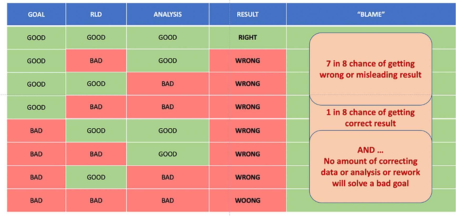
The most interesting discussions came from two of the slides I used, firstly how easy it is to get a wrong answer. The second followed on from how you get accurate and repeatable data and concerned how do you know you have transferred the data properly for analysis, and when you analyse it, how do you know the software has given a good answer.
I suggested we could see where known, simple but non-trivial, data values and signals are passed though the analysis tools where we could predict what the answers or analysis should be and see if the tools provided the answers we expected. It is good practice to do this type of thing anyway, but I suspect rarely do we as engineers do anything like this. Well,
maybe when we get a result we do not like (a failure for instance).
In recent months my mind turned back to earlier days in the EIS. One of the initiatives I was involved in was to look at the software tools we all use. Back in the late 1990s and early 2000s, the EIS set up a working group to look at Software Verification. This group worked closely with engineer users and a group of software and instrumentation suppliers to set out useable and simple data sets we could pass through the software tools, and thus be able to predict what the actual answer should be.
This produced some very interesting, possibly surprising results. The original data downloads exist and provide a ready source of ‘calibration’ data for testing out the basic workings of the majority of analysis tools. Let us see what this really means. We will assume you have the best transducers, and instrumentation and the accuracy of what you collect and assured by calibrations and certification (of course we all have this to traceable standards and is well known – you do don’t you – ISO, SAE, BS, etc). The data you collect is transferred and recorded typically into digital data, again we will assume that this is also
32
Why "the basics" are important to a development.
to some form of traceable standards as part of the instrumentation, but again are their standards and traceability here? Now comes the interesting part, we take that “accurate” data and feed it into software on a computer. How do you know the software is giving you the correct answers?
What are the traceable standards? Where are the calibrations? Do you know what your data should look like anyway? We are in the process of returning to this working group as a training aid, and to provide examples, for young engineers (and the not so young) to help in understanding the processes we seem to be taking for granted. We have re-released and made available the original data sets, and all its documentation for use by the EIS community. It covers a large set of what appears to be very simple data, that all helps the engineer to understand firstly the data itself, and then the software tools.
The working group has decided to try out the original three or four sets of data and pool the results and test out the system. If you find any problems reading in these data to your analysis tools, this may be another sign for the need to test software and maybe your procedures in data entry. Any great problems should flag some warning signs, as surely data input should be easy.
After all these are not very large files, as they were originally only intended to find some rounding error and problems in handling the higher numbers of data points back in the late 1990s. The data consists of sets of ASCII text files, covering a short file of 8000 points long, and a long file of 128000 points long. The two lengths cover certain problems originally found in time stamp number conversions in smaller computer processors. The number of data points also tests how other frame type file formats such as RPC etc handle data imports. It is important to note that the files are not intended to trick any system, just to bring home the differences in systems, formats and standards that can easily cause issues at times.
You may ask yourself: surely software tools are all set up to standards and analysis results are all the same? Unfortunately this is far from the case. Many software tools, in themselves nominally accurate and designed as well as possible, have inherent biases built into them depending on the specialist area they have evolved. This is most notable in the default settings for many of the basic statistical analyses. It has been very interesting to pass the same data set through standard tools for a series of software suppliers and to see how very different the outputs are. None of them, happily, seem to provide wrong answers, but you have to be careful when comparing say time at level plots, RAINFLOW counts, spectra etc for the same data but from different tools.
If you always do your analysis inside one software suite, and carry out all your tests in the same
manner, you may never see a problem. Comparing and reviewing results will all have the same default settings, and assumptions. But, have you thought what happens when you send data, or results to others, maybe using completely different tools? Even worse is getting data and results from others and not seeing the same values or results in your tools. I am sure this has never happened to any of you. This data can also be extremely useful as a quick, comparative check calibration on software changes and upgrades. It is quite comforting to be able to prove new or “improved” tools can still give you the same answers. We will be running a specific webinar on this topic in the near future. We can then explain more of the system and what it’s aims are. So far over the years the data sets have proven useful in discovering changes to software tool default condition, limitations in nee rich conversions, update errors etc. One notable example was on receiving a new software update, we were getting some strange results. It seems that occasionally, to save time, software developers hardwire in some defaults and variables during development. These can sometimes be left in place, by accident, and unwittingly change your personal settings. These are sometimes not as obvious as you think, and a set of data, with a known set of outputs can be useful to compare.
Finally, we had a bit of fun: I set a challenge to help the Young Engineers to understand that different software and different users can produce very different results using the same information. Typically it is easy to misjudge how software tools actually work and I have used the following simple example to help people understand.
For fun, try answering this puzzle/question, without doing it in your software. To some of you this may be totally trivial, to some it may useful. Interestingly this puzzle is based on errors I have seen a number of times over the years.
Question…
Youhavesomeroadloaddatacollectedat10Hz.A1 secondsectionofitisofinterestforrigtesting.Youare askedtoprovide10repeatsofthedataforarigtest. Ifyouextract1secondofdata,thenconcatenate(join together)10repeats,howlongisthesignal?
Again, do not do it in software. Be fair and provide an answer that you would expect. Answers should be sent to info@e-i-s.org.uk (I will keep them anonymous if needs be) as soon as you can, and I will collate a table if there are variants.
I have received 13 replies so far, with quite a variety of results. Six of them would be considered correct in predicting what would occur. The others are different with a 10% spread, as low as 10 seconds long, up to 11
33
seconds, both incorrect. I have had a few arguments about handling end values, smoothing and overlaps and blending. All valid practical points, but only add to the problems that exist in using features of specialist software that would all produce different signal lengths by different people using ostensibly the same “analysis”.

Before applying your specialty blending, smoothing, overlapping it is important to understand how the basic ideas work, and I suppose, what was wanted. The following solution should help:


I hope this has been food for thought. The working group will continue to trial the Software Verification data sets. We will run the introductory webinar soon, and provide some examples, and results. Hopefully, showing differences if just using initial defaults and, with some thought, some best practices for the future. I will, if there is interest, provide some more data analysis puzzles.

34 �
News from the Institution of Mechanical Engineers

New method ‘nearly doubles carbon capture performance’
A new method has almost doubled the performance of electrochemical carbon capture, its developers have said.
A team from Massachusetts Institute of Technology developed the technique, which could significantly boost the performance of systems that use catalytic surfaces.
“Carbon dioxide sequestration is the challenge of our times,” said mechanical engineering professor Kripa Varanasi, who worked with assistant professor Sami Khan, professor Yang Shao-Horn and recent graduate Jonathan Hwang.
There are a number of approaches, including geological sequestration, ocean storage, mineralisation and chemical conversion. Electrochemical conversion is particularly promising because it can produce useful products such as fuels, but it still needs improvements to become economically viable.
In these systems, a stream of gas containing carbon dioxide is typically passed through water to deliver carbon dioxide for the electrochemical reaction. The movement through water is sluggish, which slows the rate of conversion of the carbon dioxide.
The new design ensures that the carbon dioxide stream stays concentrated in the water right next to the catalyst surface. This concentration, the researchers showed, can nearly double the performance of the system. In electrochemical systems, the stream of carbon dioxide-containing gases is mixed with water, either under pressure or by bubbling it through a container outfitted with electrodes of a catalyst material such as copper.
A voltage is then applied to promote chemical reactions, producing carbon compounds that can be transformed into fuels or other products. Previously, the reaction has happened too quickly, and a competing reaction of water splitting has
taken over. To tackle that issue, the researchers placed a gas-attracting surface in close proximity to the catalyst material.
The material is a specially textured ‘gasphilic’, a superhydrophobic material that repels water but allows a smooth layer of gas to stay close along its surface. It keeps the incoming flow of carbon dioxide right up against the catalyst, so the desired carbon dioxide conversion reactions can be maximised.
By using dye-based pH indicators, the researchers were able to visualise carbon dioxide concentration gradients in the test cell. In a series of lab experiments using the set-up, the rate of the carbon conversion reaction nearly doubled. It was also sustained over time, whereas in previous experiments the reaction quickly faded out.
The system produced high rates of ethylene, propanol, and ethanol, a potential automotive fuel. The process could instead be optimised for hydrogen production.
By concentrating the carbon dioxide next to the catalyst surface, the new system also produced two new potentially useful carbon compounds, acetone and acetate, which had not previously been detected in any electrochemical systems at appreciable rates.
In the initial laboratory work a single strip of the hydrophobic, gas-attracting material was placed next to a single copper electrode, but in future work a practical device might be made of a dense set of interleaved pairs of plates.
35
University of Wolverhampton Racing
Sponsored by the EIS
UWR Student Innovation Continues Despite COVID-19 Restrictions
The University of Wolverhampton Racing (UWR) team are fortunate to have a wide range of sponsors that support the team to help bring student projects such as the formula student competition to life.

We are proud that the Engineering Integrity Society are among those sponsors, and we thank the Directors and all EIS members for your support.
Despite the national restrictions that have meant all students are studying from home, the UWR team have continued to work closely with their industry partners towards this year’s IMechE Formula Student competition. Recently the team have been working on improving engine performance.
One way this is being achieved is with a new intake manifold and plenum. Having an engine running at high volumetric capacity is beneficial as it increases the engine's power output; this is an even greater factor to consider as the competition mandates the use of a 20mm diameter airflow restriction. Having an intake system which evenly distributes flow whilst providing increased volumetric efficiency will significantly increase engine performance.
A goal of the new design was to improve the volumetric efficiency of the Yamaha YZF-R6 engine, with an aim to incorporate more novel design ideas that aid the massflow distribution between each intake runner. This meant, however, that these new design concepts would likely result in greater total mass of the intake system so it was extremely important to factor in design for weight
implementation of a spiral located in the funnel, which aims to increase the air-fuel mixing capability as the air continues into the combustion chamber.
The design of the regulated air restrictor was a focal point of the project. Many professional racing series adopt similar rules, meaning all airflow that is to be used for combustion must first pass through the restriction. The “venturi” design was adopted as it meant that pressure characteristics after the restriction could be recovered, if this restriction were to remain 20mm downstream then it would become very difficult to reduce losses, therefore limiting engine performance.

The final design is able to accelerate the movement of air whilst allowing pressure recovery and reducing losses, with the significantly lower pressure region inside the choked section drawing in air from upstream. To achieve this, aerodynamically efficient construction is used based on relevant calculations made to the inlet system. The Venturi effect, Helmholtz and Bernouilli’s principle were major theories used during the progress of the ram-air design.
without impacting the capability of the intake structure. Some of the major factors in the early design stages focused on were: equalization of air delivery to each cylinder, minimising pressure losses at the restrictor and improving the mass flow rate into intake runners.
The air filter underwent extensive development stages including CFD on a wide range of iterations. The results underwent comparative analysis to find the dimensions which gave the most efficient air flow into the throttle body. Further development was carried out with the

Students have developed these components alongside J-Supplied 3D, one of our partner companies. This project has stretched the possibilities of Fused Deposition Modelling (FDM) due to the high stress the components will be subjected to within the plenum’s assembly. To gain as much strength as possible the prints were completed using F3 PA-CF Pro carbon fibre filament, supplied by Fibrethree and printed on J-Supplied’s Craftbot Flow Idex and Modix 1m/1m machines.

Follow the UWR FS team’s progress on our social media platforms as we continue to work towards the completion of this year’s car for the live competition in July 2021, COVID-19 permitting.
Instagram: @uwracingfs
Facebook: UWR Formula Student
LinkedIn: UWR Formula Student
36
New intake manifold. CFD analysis of the air filter.
Test pieces printed by J-Supplied 3D in PLA.
The UK’s annual gathering of OEMs and engineering supply chain professionals will return in November 2021. Make sure your brand is part of the reunion and showcase your solutions to the engineering minds behind tomorrow’s projects.

3 & 4 November 2021, NEC Birmingham BOOK NOW
+44 (0)20 3196 4358 | aeuk@easyfairs.com
Measurement Sensors
Micro-Epsilon designs and manufactures precision sensors and measurement systems for displacement, profile, gap, thickness, distance, vibration, temperature and colour measurements.

2D/3D Laser profile sensors
Thermal imaging cameras
Optical micrometers
Turbospeed sensors
Capacitive sensors

Laser triangulation sensors
Thickness sensors
Micro-Epsilon is an expert in sensor technologies. We offer free virtual demos, webinars and online consultations, so get in touch now!
37
+44 (0) 151 355 6070 | www.micro-epsilon.co.uk
info@micro-epsilon.co.uk
|
AE_2021Advert_210x148_.indd 1 29/01/2021 20:29:51
www.advancedengineeringuk.com/exhibit
Equipmake launches new high-torque, direct drive electric motor for heavy duty commercial vehicles
Leading automotive electrification specialist, Equipmake, has launched an all-new high torque electric motor designed specifically for use in heavy duty commercial vehicles, such as electric buses.
Called the HTM 3500, the new motor combines high torque with low motor speeds, fitting directly onto the propshaft of a large electric vehicle, negating the need for a separate gearbox. Capable of producing maximum torque of 3,500Nm at just 1,000rpm, it has been designed for multiple heavy duty vehicle applications, from electric buses to HGVs and mining trucks, where high torque and start/stop duty cycles are required.
Based in Norfolk, UK, Equipmake provides EV technology to automotive OEMs and specialist supercar makers, producing everything from industry-leading highperformance electric motors to power electronic systems, all the way up to complete EV drivetrains, while also operating across marine, off-highway, agriculture and aerospace.
Equipmake’s new HTM 3500 motor is an integral part of the very latest iteration of the state-of-the-art EBus platform, with in-service trials of this technology beginning next Spring by Brazilian commercial vehicle manufacturer, Agrale, who will launch an electric bus first in Buenos Aires, Argentina in 2021.
www.equipmake.co.uk
New swarm testing capability to accelerate ADAS and autonomous vehicle development
12th January 2021 – Leading automotive test system supplier AB Dynamics has showcased its unique capability to replicate simulated swarm tests quickly and accurately in the real world and vice-versa. By using a common toolchain, complex scenario testing can be transferred from one environment to the other with centimetre accuracy. This enables the testing and development of ADAS and autonomous systems to be significantly accelerated whilst also reducing risk and cost.
As the industry continues to move towards autonomous technology the complexity of testing is increasing. AB Dynamics recently conducted a track test with VW Group where eight objects were coordinated in a swarm test using the company’s vehicle control robots and wireless telemetry system.
“We are the only company to use the same software toolchain for simulated and real world testing; this
means we can develop and run a test in the virtual world and simply ‘copy and paste’ it when at the test track,” said Jeremy Ash, Sales Director at AB Dynamics. “Swarm testing is very complex and can involve the precise choreography of eight or more test items. Our solution enables customers to run thousands of iterations of tests virtually and then confidently replicate a sample of these in the real world for correlation.”
Scenario testing using a swarm of vehicles is a vital aspect of development for ADAS and autonomous vehicle technologies. It assesses the ability of autonomous functions to interpret the behaviour and intentions of drivers and vehicles in the close vicinity.
Scenarios such as merge-in, caused by lane closures on dual-carriageways, cut-in and cut-out are common events that force a vehicle using ADAS or autonomous systems to make a decision (brake, merge, accelerate or perform an evasive manoeuvre).
AB Dynamics is unique in being able to offer this capability with a single toolchain ensuring absolute test repeatability. It has produced a video to explain the complexities of swarm testing and demonstrate its capabilities in this area.
www.ABDynamics.com
Ramboll’s True Digital Twin demonstrates its potential to increase lifetime of offshore wind structures
5 January 2021 – Ramboll has reached an impressive milestone in the ROMEO project, demonstrating the great potential of its innovative True Digital Twin technology through a pilot-test that has been conducted at the Wikinger offshore wind farm in the Baltic Sea. The pilot-test – based on a measurement campaign using Structural Health Monitoring (SHM) solutions –revealed a significant potential for lifetime extension for the offshore substation and the offshore wind turbine foundations.
The results of the pilot-test have been summarised in two reports which Ramboll has delivered to its ROMEO project partners. According to the reports, the full power of a True Digital Twin lies within the continuous monitoring of the factors that can affect the structural integrity of a wind turbine over its entire lifetime. The monitoring process can be done at all possible locations using SHM solutions, cloud computing and advanced mathematical calculations.
Based on only a few sensors at easily accessed locations, the patterns of movements are captured to let the True Digital Twin undergo the full history of loads. The True Digital Twin can detect structural integrity issues like failure of jacket braces, excessive scour or corrosion.
38
Product News
Extensive simulation studies showed that monitoring modal properties like natural frequencies and mode shapes not only can detect anomalies but can also identify the type of anomaly if combined with a design model database.
“The concept of the True Digital Twin makes detailed design models available for predicted lifecycle management and provides the framework to incorporate measurement findings of a specific turbine into the simulation world. We can track the history of exposure of an individual structure or detect damages and replace the extensive instrumentation of traditional methods with mathematical calculations”, explains Ursula.
During the next phases of the ROMEO project, Ramboll and its partners will continue exploring the added value of continuously monitoring offshore wind structures. The project partners anticipate a reduction of human offshore time for annual inspections and a reduction in the number of planned time base offshore visits.
www.ramboll.com
WEG launches decentralised drive package with WG20 geared motors and MW500 VSDs
WEG, a global leader in drive technology, has announced availability of a decentralised drive package, consisting of WG20-series gear units, EUSAS motors and a MW500 variable speed drive (VSD). Compared with traditional drives, this compact and decentralised package provides lower energy consumption and a compact footprint, as well as improved flexibility.
The decentralised drive package can be used for a broad spectrum of applications, including machines in intralogistics, such as warehouse systems and conveyor belts. Other potential applications include speedcontrolled fans, pumps and filling systems, which are common-place in the food industry.
Members of the MW500 VSD family can be used for a range of applications in the 0.12 to 9.2 kW range for line voltages of 380–480 V. The equipment is also available in three frame sizes (A, B and C), and from 0.12 to 1.5 kW for 200–240 V with WEG’s WG20 geared motor series, which is available in models with helical, parallel shaft and helical bevel gear units.
www.weg.net
PandarXT: 32-Channel Mid-Range LiDAR
The laser's transmitting and receiving systems are based on Hesai's self-developed ASICs, greatly improving LiDAR performance and reducing costs and production complexity.
PandarXT precision (1σ) is up to 0.5 cm; greater precision performance than comparable products on the market. PandarXT continuously outputs valid point cloud even when objects directly touch the LiDAR’s enclosure. This enables the self-detection of enclosure smear and occlusion.
With double the number of lasers and resolution
compared with typical mid-range LiDARs (16 channels) and range detection up to 120 m, POD>90% when detecting 10% reflectivity targets at 80 m (middle 16 channels), every pulse has its own ‘fingerprint’, rejecting noise when multiple LiDARs operate closely together.
Alongside high accuracy and consistency, and greater dynamic range, PandarXT provides more accurate reflectivity information for algorithms.
PandarXT has passed strict reliablity tests including high temperature operation, low-temperature wakeup and operation, thermal shock/air-to-air, vibration with thermal cycling, mechanical shock, humid heat, cyclic, frost, water- and dust-proof, and shipping vibration. It is robust and reliable in any operational environment.
www.hesaitech.com
HBK introduces configurable piezoelectric force measurement chain CMC
HBK has created new CMC piezoelectric force measurement chains which can be freely configured in more than 200 combinations, making them ideal for a range of industrial measuring tasks, such as joining, forming or assembly processes.
Users can select a sensor that matches their required measuring force, potential initial load, and desired overload range. The selection of the amplifier depends exclusively on the force to be measured, which enables a high output signal and good resolution.
Each measurement chain comprises a sensor, a charge cable, a charge amplifier, and the associated test protocol that documents the relationship between the force in Newtons and the output signal in volts. To improve user accuracy, HBK also specifies the calibration results for multiple force ranges.
Charge cables in different lengths are available to allow for easy integration. CMC force measurement chains are suitable for rapid measurements and force-displacement monitoring, as the sensor's deflection does not affect the displacement measurement.
Plus, all HBK’s measurement chains meet the required IP65 degree of protection. A switching input allows for zero-balancing of the charge amplifiers and a magnifying function can be activated to ramp up the amplifier’s sensitivity.
Sensors with nominal forces ranging from 5 kN to 120 kN are available. The charge amplifiers have input ranges between 1000 pC and 482,000 pC, with the resulting nominal measurement ranges varying from 125 N to 120 kN.
www.hbkworld.com
39
Contributions to Product News may be emailed to managingeditor@e-i-s.org.uk. The nominal limit for entry is 200 words.
News from the Women's Engineering Society
At the last time of writing, the UK seemed to have “flattened the pandemic curve” and was enjoying a partially restricted summer. Covid-19 looked to be on the run, and though a second wave was predicted, I doubt anyone would have thought that it would be as awful as it was, with even greater misery to come.
My household is shielding to protect an extremely vulnerable member, so none of us have left the house since before Christmas. We have groceries and other goods delivered, and a local volunteer sorts out prescriptions. If the supermarket doesn’t have something, we do without. I am aware that I am much more fortunate than many others, able to do my job from a cosy house with very fast broadband and a garden full of birds.
And so my mind turns to the engineers who are keeping us safe in the pandemic, whether maintaining our power, heat and light, clearing the roads, ensuring our safety, or designing robot pickers for warehouse deliveries.
And then I think about the engineers that keep us safe at other times. It’s not an accident that concrete is being used to upgrade the central reservations on UK motorways. Concrete prevents vehicles that hit the crash barriers from jumping into the oncoming traffic, reducing fatalities. The shape is designed to absorb the energy produced and stop vehicles safely.
There are so many of these types of project underway –the massive sewer being built under the River Thames in London by Thames Tideway, to stop water pollution and improve the health of Londoners. Its tunnel-boring machine at Fulham is named Rachel, after WES’ First President, Rachel Parsons.
Other projects include developing and building lifesaving devices like pacemakers, ventilators, body scanners and ECMO machines that relieve the heart and lungs by doing their job for them outside the body. Or producing diagnostic tests and vaccines to protect us from everyday diseases that used to kill us like measles, and now COVID.

We at WES are so inspired by those keeping us safe that we have decided that the theme for our 2021 Top 50 Women in Engineering is Engineering Heroes. It is partly to celebrate those women who are saving lives during the pandemic, or who respond in emergencies to natural and manufactured disasters such as floods, earthquakes, and structural collapse. But it is also to celebrate those who keep us safe as described above. It is frustrating that the amazing engineering achievement to shore up the Todmorton Dam was attributed to “construction

workers” rather than Major Angela Laycock and her team of Royal Engineers, who also built the Birmingham Nightingale Hospital.
These heroes are not new. Dr Beatrice Shilling blazed a trail for women in engineering all her life. As an apprentice working on rural electrification in Devon, she was caught working alone in a power station, in contravention of the ILO convention on night working for women. Her employers were WES members, Margaret Partridge and Dorothy Rowbotham and WES took on the ILO and changed the convention. Shilling then became one of the first women to study engineering at Manchester University. Her war work for the Royal Aircraft Establishment led to the development and fitting of “Miss Shilling's orifice", a small metal disc similar to a metal washer that restricted fuel flow to a carburettor. This helped prevent engine stall in the Merlin engines, enabling the Spitfires and Hurricanes to beat the fuel injected Messerschmitts during the Battles of Britain and France.
After the war, Shilling continued to work in aerospace, including the effect of rain and snow on braking aircraft, determining that drag due to snow on the runway was the cause of the Munich Air Disaster, and not pilot error. Life support for crews at high altitude was another important aspect to her work, as well as design of bobsleighs, motorcycle engines, and Grand Prix car cooling systems. Incidentally, she was also the second woman to win a Gold Medal at Brooklands, lapping more than 100mph on her motorbike, and it is rumoured, insisting that her husband achieve the same feat before she married him.
I believe that if Beatrice Shilling had been called Benedict (her male counterpart in Shakespeare’s Much Ado About Nothing), we would know of her achievements from the books written, films made and legends told about her. The Women’s Engineering Society hopes that by celebrating the work that engineers do behind the scenes, many more people will come to know and respect engineering.
Elizabeth Donnelly Chief Executive Officer www.wes.org.uk
40
Group News
this specialised subject. Enlightening young engineers and demystifying S&V engineering is an ongoing challenge if we are to encourage young engineers to become the creative S&V engineers of the future.
Dave Fish Chairman
Sound & Vibration Product Perception Group
The Sound and Vibration Product Perception Group (SVPP) has two objectives for 2021: increase the representation of academia on the committee and to run free webinars aimed at young engineers.
I am pleased that we now have new committee members who joined in January 2021, with representation from Birmingham, Bradford, Brighton, and Swansea universities. Having input and support from academics and universities is valuable, given that our primary objective is to offer a forum for industrial engineers to exchange ideas and experience. We welcome them on board and look forward to their support and contributions to the SVPP Group over the coming months and years.
By the time you read this, we will have presented our first webinar as part of the EIS Young Engineers Forum. This webinar took place on 11 February: “Sound and Vibration Engineering: what, where and how?”. The webinar looked at what sound and vibration (S&V) engineering is about, where in industry it is practiced, and how it is used within those industries.
As a high-level exploration of the world of S&V engineering, this was aimed at young engineers who may be interested in a career or simply want to increase their awareness of
Durability & Fatigue Group
Another journal issue and we find ourselves still under the cloud of COVID-19 pandemic restrictions. I think that all would agree the situation for our industries and academic research is not good; the aerospace sector especially is proceeding with considerable caution.
Things are far from those projections which seemed fair or best-case last spring, but overall it is not as bad as some of the darkest predictions. Many engineering laboratories struggled greatly during the first half of 2020 with the questions of what counted as “essential”, whether they could legally continue operations under lockdown, or whether they should ethically ask staff to come in. Fortunately, most have found, in the
end, that only minor changes are needed in most working procedures to operate in a “COVID-safe” manner. Within our own Durability and Fatigue Group, I am sorry to say that we have not succeeded in progressing some of the webinars we had hoped to, perhaps because most of our committee members are still as busy as ever. However, due to great efforts by our Marketing & Events Manager, the Fatigue 2021 conference will still be going ahead at the end of March, but now as an online and ondemand conference. Fortunately we had taken the decision, in November, to prepare and evaluate options for a partially or fully virtual meeting, and those plans have now been put into action.
To provide a little commentary on developments of interest in the world at large, it would be fair to say that the drive for energy efficiency and a low-carbon economy continues apace. That has manifested in lots of activity on electric vehicles and battery technologies, but also a noticeable increase in focused research for hydrogen storage. With such small molecules to contain, hydrogen storage must unavoidably depend on either all-metal or metallaminated infrastructure, but metals are not immune to their effects either. Hydrogen embrittlement of metals has been known for a long time and an ongoing research area.
Yet to date it had remained a niche interest, since its impact is insignificant for most aspects of transport and civil engineering; needless to say, if we are to develop a widespread hydrogen infrastructure it must become a core competency in designing for durability.
Peter Bailey Chairman
41
Simulation, Test & Measurement Group
Most of us are now accustomed to working from home, and although some are relishing the opportunity to reduce travel, save on the stress of the commute and reduce our fuel bill and the impact on the carbon footprint, the ‘home office’ has its downsides.
Personally, I find I spend most of my day in virtual meetings, looking at the same four walls. The trip to the coffee machine is no longer a social event where you can catch up on other colleagues’ health, social life (if only) and project activities, but merely a trip to the kitchen and a
show of affection to the dog who still wonders why you are invading his ‘quiet’ time before his walk. So where am I going with this? Well, I think most of us thought we would achieve a greater level of work from home and enjoy more ‘down’ time with the family. I imagined more time to plan and take part in seminars, listening to new engineering capabilities or refreshing our minds on the latest strain gauge techniques, but alas it doesn’t seem to be the case (for me at least).
As mentioned in September, the STMG was discussing various webinars for January/February 2021 but unfortunately the launch date has slipped as many members are under intense work pressure, struggling with defining when ‘work time’ starts and stops.
Therefore, at January’s meeting I wanted to focus and re-energise the group, perhaps finding some new and interesting topics to present in the hope of rekindling the enthusiasm and drive we have achieved in the past. We discussed several topics in a similar vein that will present a new ‘dynamic’. Members from a wide manufacturing spectrum
Corporate Members
have promised to liaise with their colleagues about recent papers and processes and encourage them to share information via the EIS forum. Our group is not just formed of motor engineers but includes experts in aerospace and earth movers with other complex issues to overcome when considering measurements which feed into many engineering attributes.
Therefore, after a slow end to last year, I hope in 2021 we can catch up with our Young Engineers Forum in offering several presentations that will attract and interest the wider engineering community. For some it will be a refresher and for others a dive into something new.
I am now looking forward to September’s journal to report on our successes, fingers crossed. The upcoming webinar will be recorded and we intend to share this via the EIS website to encourage more interest in other future events. Here’s looking forward to a 2021 full of events to enjoy!
Steve Payne Chairman
The following companies are corporate members of the Engineering Integrity Society. We thank them for their continued support which helps the Society to run its wide-ranging events throughout the year.
AcSoft
Bruel and Kjaer
CaTs3
CentraTEQ
Correlated Solutions
Dassault Systemes
Data Acquisition and Testing
Services Ltd
Data Physics
Datron Technology
Dewesoft
Gantner Instruments
GOM
HBM
HEAD acoustics
HORIBA-MIRA
imc Test and Measurement
GmbH Instron
Interface Force Measurements
iPetronik
Kistler
M&P International Mecmesin
Micro Measurements
Micro-Epsilon
Millbrook
MOOG
Nprime
PCB Piezotronics
PDS Hitech
Phoenix Materials Testing Ltd
Polytec Prosig
Rutherford Appleton Lab
Sensors UK
Serco
Servotest
Severn Thermal Solutions
Siemens
Star Hydraulics
Strainsense
StressMap Ltd
Systems Services
Techni Measure
THP Systems
Torquemeters
Transmission Dynamics
Zwick/Roell
42
Committee Members
President: Professor Roderick A Smith, FREng. ScDDirectors
Peter Bailey, Instron
Robert Cawte, HBM United Kingdom
Graham Hemmings, Engineering Consultant
Richard Hobson, Serco Rail Technical Services
Nick Richardson, Servotest
Norman Thornton, Engineering Consultant
John Yates, Engineering Consultant Chairman
John Yates, Engineering Consultant Vice Chairman
Richard Hobson, Serco Rail Technical Services Treasurer
Graham Hemmings, Engineering Consultant Company Secretary
Nick Richardson, Servotest Marketing & Events Manager
Sara Atkin
Communications Sub Committee – ‘Engineering Integrity’
Journal of the EIS Honorary Editor
Spencer Jeffs
Managing Editor
Rochelle Stanley
Sound & Vibration Product Perception Group
Chairman
David Fish, JoTech
Deputy Chairman
Keith Vickers, Bruel & Kjaer UK
Members
Dave Boast, DB Engineering Solutions
David Bryant, Bradford University
Mark Burnett, HORIBA-MIRA
Pierfrancesco Cacciola, University of Brighton
Martin Cockrill, Polytec
Paul Francis, JCB
James Herbert, Bruel & Kjaer UK
Peter Jackson, European Acoustical Products
Paul Jennings, Warwick University
Amir Khan, Bradford University
Chris Knowles, Consultant
Andrew McQueen, Siemens
Jon Richards, Engineering Consultant
Alexander Shaw, Swansea University
Tony Shepperson, HEAD acoustics
Simulation, Test & Measurement Group
Chairman
Steve Payne, HORIBA-MIRA
Deputy Chairman
Alex O'Neill, Jaguar Land Rover/University of Surrey
Members
Jack Allcock, Tata Steel
Carl Barcock, Data Acquisition & Testing Services Ltd
Dan Bailey, Instron
Gian Matteo Bianchi, Jaguar Land Rover
Connor Bligh, JCB
Marc Brown, Vibration Research
Darren Burke, Servotest
Lloyd Butler, DTR VMS
Steve Coe, Data Physics (UK)
David Copley, Consultant
David Ensor, Enginerring Consultant
Robin Garvie, Airbus
Graham Hemmings, Engineering Consultant
Richard Hobson, Serco Rail Technical Services
Jerry Hughes, Moog
Ben Huxham, Prosig
Chris Johnson, Wacker Neuson UK Ltd
Jonathan Joy, Millbrook
Virrinder Kumar, HBM United Kingdom
Trevor Margereson, Engineering Consultant
Tim Powell, MTS Systems
Anton Raath, CaTs3
Gary Rands, Siemens
Nick Richardson, Servotest
Paul Roberts, HBM Prenscia
Raul Rodriguez, Hyster Yale
Jarek Rosinski, Transmission Dynamics
Norman Thornton, Engineering Consultant
John Wilkinson, Engineering Consultant
Darren Williams, Millbrook Proving Ground
Scott Williams, Williams F1
Rob Wood, GOM
Jeremy Yarnall, Data Acquisition and Testing Services Ltd
Durability & Fatigue Group
Chairman
Peter Bailey, Instron Secretary
Jamie Shenton, JCB Members
Hayder Ahmad, Safran
Martin Bache, Swansea University
Andrew Blows, Jaguar Land Rover
Robert Cawte, HBM United Kingdom
Amir Chahardehi, Atkins Energy
Richard Cornish, Birmingham City University
Farnoosh Farhad, Northumbria University
Hassan Ghadbeigi, Sheffield University
Lee Gilbert, Element
Oliver Greenwood, Rolls Royce
Phil Irving, Engineering Consultant
Karl Johnson, Zwick Roell Group
Chris Magazzeni, Oxford University
Angelo Maligno, IISE, University of Derby
Andrew Mills, Siemens
Giovanni De Morais, Dassault Systèmes Simulia
Davood Sarchamy, Airbus
Giora Shatil, Darwind
Niall Smyth, Coventry University
John Yates, Engineering Consultant
Committee members can be contacted via the Marketing & Events Manager, Tel: 01623 884225.
44
Corporate Member Profiles
Correlated Solutions, Inc.
121 Dutchman Blvd., Irmo
SC 29063, USA
Tel: +1-803-926-7272
Email: Sales@CorrelatedSolutions.com
Website: www.correlatedsolutions.com
Official UK Distributor: Enabling Process Technologies, Ltd. | T: +44 (0) 117 205 0077 | Sales@EPTworld.com | www.eptworld.com |
Correlated Solutions, Inc. develops advanced, noncontact, full-field digital image correlation (DIC) and digital volume correlation (DVC) measurement systems to quickly and accurately measure surface shape, motion, deformation, and strain of a material of any size under almost any loading condition.
Our turnkey systems are fast, robust, & flexible, and are available for a wide range of applications including quasi-static, high-speed (up to 300KHz), ultra-high-speed (up to 5MHz), stereo-microscopy, Thermal (integrated IR), real-time, transient vibration (ODS) measurements, and NDT defect detection.
Gantner Instruments GI Systems Ltd
1 The Old Stables, Eridge Park
Tunbridge Wells, TN3 9JT
Tel: +44 (0)1323 332105
Email: info@gismtt.com
Website: www.gismtt.com
Contact: Rob Stockham
Gantner Instruments are leaders in the acquisition of electrical, thermal and mechanical measurement. You will find our know how in all of our products and services. While our products exhibit high performance and flexibility they remain simple to operate and easy to understand, even in complex applications.
Every Gantner product is designed and built to provide high precision and reliable operation in the most extreme industrial environments. High temperatures and EMC conditions are no problem for us. Our products are manufactured to EN ISO 9001 standards and have an average MTBF (Mean Time Between Failure) of over 20 years.
Data Acquisition & Testing Services Ltd
Unit 4 Gainsborough Close, Gainsborough Business Park
Long Eaton, Notts, NG10 1PX
Tel: +44 (0)1332 875450
Email: enquires@datsltd.com
Website: www.datsltd.com
Contact: Jeremy Yarnall
Data Acquisition & Testing Services provides data acquisition, test and measurement, instrumentation, analysis and engineering consultancy services across a wide spectrum of industries, from aerospace to rail. Based near Derby, with field engineers available nationally and outside the UK.
Additionally, we provide sales and service of the latest digital data collection equipment, with a full calibration facility for instruments and sensors. Hire of dataloggers, sensors and cables is also offered. Vibration, and durability testing is provided in our in-house laboratory.
Polytec Limited
Unit 8, The Cobalt Centre
Siskin Parkway East Coventry, CV3 4PE
Tel: +44 (0)1582 711 670
Email: info@polytec-ltd.co.uk
Website: www.polytec.com/uk/
Non-contact optical measurements
Polytec manufactures a wide range of laser vibrometers that are the acknowledged goldstandard for non-contact vibration measurement. No matter your measurement need in research, development and production or even for long-term monitoring, there is a Polytec system to provide the answer. Laser-Doppler vibrometers analyse samples of different size, from entire car bodies, large aerospace parts over engines and actuators to micron-sized MEMS or delicate HDD components, even biological samples. Polytec also provide noncontact velocimeters for industrial process length & speed measurements, as well as optical profilers for surface metrology applications using the latest advances in white light interferometry.
45
Systems Services
The Coach House
303 Willington Road
Kirton End, Boston, PE20 1NR
Tel: + 44(0)1205 724242
Email: stephen.barrett@systemsservices.co.uk
Website: www.systems-services.co.uk
Contact: Stephen Barrett – Tel: +44 (0)7836 607414
Since 1982, Systems Services have offered a complete service for fluid power motion control systems, ranging from a single channel to multiaxis, multi-channel, interactive, full scale systems. Our range of services includes consultancy, training, associated servicing and calibration, calibration management, commissioning, gas-loaded accumulator management & related technical procurement services.
We offer a range of customised training courses for all users of fluid power systems and have trained over 720 delegates.
Transmission Dynamics (JR Dynamics Ltd)
Unit 4 Arcot Court, Nelson Road Cramlington, Northumberland, NE23 1BB
Tel: +44 (0)191 58 000 58
Email: wsupport@jrdltd.com
Website: www.jrdltd.com
Contact: Prof. Jarek ROSINSKI (CEO)
Transmission Dynamics is a rapid response consultancy organisation specialising in troubleshooting problems in rotating machinery.Our areas of expertise are: failure investigation, noise and vibration research, in-service load measurements, component fatigue life evaluation, bespoke instrumentation and evaluation of gear alignment to ISO-6336 (Method A). Transmission Dynamics provides services to blue-chip technology companies across the globe, including clients in the renewable energy, mining, marine, defence, automotive and rail sectors. We also design and manufacture our own range of wireless telemetry and data acquisition systems, focusing on low power consumption, exceptionally low noise and unbeatable performance, for recovering inservice load information from the most demanding of environments.
Torquemeters Ltd
West Haddon Road, Ravensthorpe Northamptonshire, NN6 8ET
Tel: +44 (0)1604 770232
Email: sales@torquemeters.com / info@ torquemeters.com
Website: www.torquemeters.com
Contact: Geoff Robinson – Sales & Marketing Director
Peter Rogers – Business Development Manager
Jane Davies – Sales Administrator
Pioneers in the design, manufacture and support of torque measurement systems for high-speed & high-power rotating applications, Torquemeters is a provider of specialist torquemeters, couplings, flywheels, spindles and turnkey test rigs.
A key partner to the major aero engine, automotive, industrial machinery and industrial gas turbine manufacturers, Torquemeters has over 2,500 systems installed worldwide. At the forefront of testing the next generation of e-motor & e-propulsion systems, recent projects include a 2MW 30,000rpm regenerative test-stand system for starter/generator testing.
ZwickRoell
Southern Avenue, Leominster Herefordshire, HR6 0QH
Tel: +44 (0)1568 615201
Email: alan.thomas@zwick.co.uk
Website: www.zwick.co.uk
Contact: Alan Thomas
ZwickRoell is a leading, global supplier of advanced materials and component testing equipment. We offer a wide range of both electro-mechanical and servo-hydraulic testing products and controller/ software modernisations to give older generation systems a new lease of life.
We supply standard and bespoke testing solutions and collaborate with an extensive range of industrial customers and academic establishments where Zwick equipment is used for both teaching and research purposes.
46


Experts in Vibration


m+p international supplies high-performance software and instrumentation for vibration control on a shaker, noise and vibration analysis, data acquisition and monitoring.

Our products combine efficiency, accuracy, flexibility and test safety. Above this, we also offer consultancy and support to ensure successful outcomes for all of your applications.
Tackle your unique challenges with m+p international’s engineering excellence.
© Thorsten Spoerlein –iStock/Getty Images Plus www.ahlersheinel.de www.mpihome.com m+p international (UK) Ltd Mead House Bentley, Hants GU10 5HY Phone: +44 1420 521222 sales.uk@mpihome.com
