Triaxial MFL Combo delivers outstanding defect detection and sizing by using hall effect sensors to record the magnetic flux leakage axial, circumferential and radial vectors. This UHR sensor technology, sampling every 2mm along the pipe, makes it possible to identify linkages between individual pits/pinholes and circumferential slotting and grooving.
C O NTENTS
03. Editor's comment
05. Pipeline news
Contract news and updates on EACOP construction, TC Energy's independent pipeline business and China's West-East Gas Pipeline.
KEYNOTE: MENA REPORT
09. A playbook for increasing asset reliability
Learn how OQ Upstream, Oman, established a centralised digital asset performance management system.
14. Capacity for growth, potential for calamity
World Pipelines’ Contributing Editor, Gordon Cope, discusses MENA’s current midstream situation and growth potential, in the face of regional conflicts and geopolitical complexities.
SUBSEA REPAIR
37. Clamping down on subsea repair
Kristen Andrew Foshaug, Chief Technology Officer, Connector Subsea Solutions.
GATHERING PIPELINES
43. Pin-point precision for pipeline protection Jun Zhang, Atmos International.
INTEGRITY AND INSPECTION
48. Tackling complex challenges with a dual-tool assembly
Manuel Alonso and Hans Overdijkink, Intero Integrity Services B.V., Netherlands.
OPERATIONAL TECHNOLOGY
21. Emerging fluids, data impacts and the future of pipelines
Paul Dickerson, Emerson.
PIPELINE SERVICES
27. A new dawn for pipeline leaks
Stuart Mitchell, President and CTO, PipeSense.
UPSTREAM PIPELINES
31. Rising to challenges in the North Sea Paul Chittenden, Subsea Inspection Technology Advisor, TSC Subsea, UK.
TACKLINGCOMPLEXCHALLENGES
55. Getting the job done, all-in-one Maja Hornig, TIB Chemicals.
TRENCHLESS TECHNOLOGY
61. A trenchless tutorial
John Barbera, Barbco Inc. and Drake Barbera, BGN Trenchless Consulting, USA.
long-term corrosion prevention solutions, including their Protal™ range of high build, fast cure liquid epoxy coatings.
EDITOR’S COMMENT
CONTACT INFORMATION
MANAGING EDITOR
James Little james.little@palladianpublications.com
Palladian Publications Ltd, 15 South Street, Farnham, Surrey, GU9 7QU, UK Tel: +44 (0) 1252 718 999 Website: www.worldpipelines.com
Email: enquiries@worldpipelines.com
Annual subscription £60 UK including postage/£75 overseas (postage airmail). Special two year discounted rate: £96 UK including postage/£120 overseas (postage airmail). Claims for non receipt of issues must be made within three months of publication of the issue or they will not be honoured without charge.
Applicable only to USA & Canada: World Pipelines (ISSN No: 1472-7390, USPS No: 020-988) is published monthly by Palladian Publications Ltd, GBR and distributed in the USA by Asendia USA, 701C Ashland Avenue, Folcroft, PA 19032. Periodicals postage paid at Philadelphia, PA & additional mailing offices. POSTMASTER: send address changes to World Pipelines, 701C Ashland Avenue, Folcroft, PA 19032.
In September, Assistant Editor, Isabel Stagg, and I attended the biennial International Pipeline Conference and Expo, joining over 7500 fellow pipeliners as they converged upon Calgary, Alberta. Enthusiasm for the prospects of the pipeline sector was high, amid the usual concerns about regulatory obstacles, infrastructural constraints, and the decarbonisation pressures associated with the global energy transition.
Canadian energy company Enbridge had some big news in October, with the announcement that it will be constructing and operating crude oil and natural gas pipelines in the US Gulf of Mexico (GoM) to support the newly sanctioned Kaskida oil hub, which is managed by British oil giant bp.
The new crude oil pipeline, named the Canyon Oil Pipeline System, will have a capacity of 200 000 bpd. In addition, the new Canyon Gathering System, a natural gas pipeline with a capacity of 125 million ft3/d, will connect subsea to Enbridge’s existing Magnolia Gas Gathering Pipeline. These projects are slated to become operational by 2029, with an estimated investment of US$700 million.
The Kaskida hub is bp’s sixth operational hub, and is expected to commence oil production in 2029. It will feature an innovative floating production platform with an initial capacity of 80 000 bpd, drawing from six wells. bp’s GoM output averaged 300 000 bpd in 2023, with a goal of reaching 400 000 bpd by 2030. Located in the Keathley Canyon area about 250 miles southwest off the coast of New Orleans, the Kaskida project unlocks the potential future development of 10 billion bbls of discovered resources in place across the Kaskida and Tiber catchment areas.
In a related development, Shell has confirmed its final investment decision for the Rome Pipeline, designed to facilitate the export of oil produced from the Kaskida project. The Rome Pipeline, set to begin operations in 2028, aims to enhance connectivity between the Green Canyon Block 19 pipeline hub and the Fourchon Junction facility on the Louisiana Gulf Coast.
Kaskida is in a prime location, with a stable fiscal regime and access to market. It will also be bp’s first development in the GoM to produce from reservoirs that will require well equipment with a pressure rating of up to 20 000 psi. If you’re interested in learning more about this, and other, upstream projects, subscribe to receive a free bi-monthly digital copy of our sister magazine, Oilfield Technology
In this issue of World Pipelines, we start with a focus on pipelines in the MENA region. OQ Upstream presents a case study from Oman, where OQ is working toward maximising value for Omani energy and ensuring a sustainable future through asset optimisation and digitisation (p.9). Correspondent Gordon Cope then provides an outline of the key pipeline projects in the region (p.14). Later in the issue, TSC Subsea writes about carrying out an internal rigid riser inspection for bp (p. 31); Connector Subsea Solutions describes technology for deepwater or diverless pipeline repairs (p.37); and Atmos International considers the growing significance of produced water pipeline leak detection in gathering networks (p.43).
Don’t miss next month’s annual World Pipelines Integrity issue, which will offer insight into inline inspection, composite coatings, field joint coatings, internal flow coatings, software and systems, automation, data, and pipeline materials.
SENIOR EDITOR Elizabeth Corner elizabeth.corner@palladianpublications.com
Still pioneers.
WORLD NEWS
Summit Midstream announces acquisition of Tall Oak Midstream
Tailwater Capital LLC, an energy and environmental infrastructure private equity firm, has announced that it has entered into definitive agreements with Summit Midstream Corporation and its wholly owned subsidiary Summit Midstream Partners, LP, whereby Summit will acquire Tall Oak Midstream Operating, LLC and its subsidiaries for a total consideration of approximately US$450 million.
Consideration is comprised of US$155 million in cash, approximately 7.5 million shares of a combination of SMC Class B common stock and common units of the Partnership (in an Up-C structure), representing approximately 40% ownership in the pro forma company, and up to US$25 million contingent consideration in cash over certain measurement periods to 31 March 2026.
The transaction is expected to close in the 4Q24, subject to customary closing conditions, shareholder approval and regulatory approvals. Upon closing, four directors appointed by Tailwater Capital will serve on the pro forma Summit Board.
Tall Oak is a leading, large-scale gas gathering and processing system in the Arkoma Basin comprised of two 220 million ft3/d natural gas processing plants and
approximately 244 miles of low-pressure natural gas gathering lines, 167 miles of high-pressure natural gas gathering lines and 65 000 horsepower of field and plant compression.
“This transaction represents a unique opportunity to partner with the Summit organisation to support the long-term growth and value creation initiatives already underway at the Company,” said Jason Downie, Co-Founder and Managing Partner at Tailwater. “The Tall Oak assets are complementary to Summit’s existing gas portfolio, and we believe the Company is well positioned to drive even more value for shareholders over the coming years.”
“Our entire Tall Oak team has done an exceptional job delivering high-quality service while prioritising reliability and safety, and I am confident that the Summit team will continue to execute and capitalise on new and exciting opportunities in the Arkoma Basin,” said Ryan Lewellyn, President and Chief Executive Officer at Tall Oak Midstream.
“Tailwater has been an invaluable partner for our business, and we are excited to continue to work with Tailwater, not only on the transition of Tall Oak to Summit but also on future potential projects under the Tall Oak name.”
US DOT increases grant funds for state pipeline and underground gas storage safety programmes
The US Department of Transportation’s Pipeline and Hazardous Materials Safety Administration (PHMSA) is awarding US$85.9 million in grants to states to support pipeline and underground natural gas storage (UNGS) inspection activities carried out by state inspectors covering more than 85% of the nation’s 3.3 million mile pipeline system.
This year’s award package includes a 33% (US$21.5 million) increase in comparison to Fiscal Year 2023 funding levels and will further enable PHMSA’s state partners to hire new pipeline inspectors, provide training, conduct pipeline inspections, and purchase and maintain equipment necessary to carry out their pipeline safety missions.
“We are grateful for Congress’ bipartisan support this year to match the increase in pipeline safety oversight responsibilities of PHMSA and our state partner inspection programmes,” said PHMSA Deputy Administrator Tristan Brown. “This year’s increase in grant awards will help ensure our states can keep up with the growing challenges of helping oversee the largest hazardous pipeline system in the world.”
PHMSA will distribute US$82 million in Pipeline Safety State Base (Base) Grants and US$3.9 million in UNGS Grants to reimburse up to 80% of participating states’ inspection and enforcement costs. Nearly all states receive state inspection programme grants from PHMSA, and 13 states receive UNGS Grants. Base and UNGS grant awards are calculated based on the state’s estimated safety programme costs. Base grant awards are also contingent on the results of PHMSA’s most recent annual programme evaluation and progress report scoring for each state agency.
In its FY 2024 budget request, the Biden-Harris Administration proposed the US$21.5 million increase in
funding to support the growing challenges incurred by states in helping hire, train, and carry out pipeline safety inspections and enforcement actions. On 24 March 2024, President Biden signed the 2024 funding bill into law, which included the requested increase and was supported by bipartisan votes in the House of Representatives and the Senate.
The National Association of Pipeline Safety Representatives (NAPSR), which represents state pipeline safety programme offices that help carry out Federal pipeline safety regulations through annual certifications and agreements with PHMSA, also supported the increase. Recognising the benefit of this funding, the NAPSR National Chair and New York State Public Service Commission’s Chief of Pipeline Safety Kevin Speicher remarked, “The recent increase in grant funding levels helps move towards closing the gap that exists between current funding of pipeline safety grants and the resources needed to ensure the continued safe operation of gas and hazardous liquid pipelines under the jurisdiction of NAPSR state programmes.”
“This funding will go far to protect our land and water from pipeline incidents” said Dave Danner, Chair of the Washington Utilities and Transportation Commission. “It will allow state pipeline safety programmes like ours to retain and attract high quality talent as well as the equipment necessary to maintain safety and environmental accountability.”
“The meaningful increase in funding is fantastic news,” said Bill Caram, Executive Director of the Pipeline Safety Trust. “State programmes are critical to pipeline safety, and these funds provide states with the resources needed to effectively meet their public safety mandates.”
WORLD NEWS
TC Energy launches independent crude oil pipeline business
IN BRIEF
USA
Diamondback and Kinetik will buy a stake in the EPIC crude pipeline. The companies will each own 27.5% of EPIC Crude, while parent EPIC Midstream will continue to own a 45% stake in the pipeline.
ARGENTINA
Bolivia’s gas exports to Argentina ended in September. Argentina, which has had a negative energy trade balance for years, is nearing the completion of projects that will allow it for the first time to export gas to its South American neighbours via pipeline and to global markets through LNG shipments.
USA
Wood is to design the DeLa Express natural gas pipeline project in Texas and Louisiana, being developed by DeLa Express LLC, a subsidiary of Moss Lake Partners LP. The proosed pipeline will deliver liquids-rich natural gas from the Permian Basin of West Texas to the US Gulf Coast and international export markets.
CANADA
ATCO Energy Systems has announced a key regulatory filing to advance the Yellowhead Mainline natural gas project in Alberta.
NORWAY
Norway’s Equinor has scrapped plans to export blue hydrogen to Germany, claiming the hydrogen pipeline hasn’t proved to be viable.
AFGHANISTAN
Turkmenistan and Afghanistan have now begun construction of the Afghan section of the Turkmenistan-AfghanistanPakistan-India (TAPI) natural gas pipeline. The staged installation of the TAPI pipeline, already completed in Turkmenistan, will eventually transfer 33 billion m3 of Turkmen natural gas annually to Afghanistan, Pakistan, and India.
TC Energy Corp. has completed its spinoff of South Bow Corp., its crude oil pipelines business, as an independent company.
The new company, which will be headquartered in Calgary with an office in Houston, will be led by Bevin Wirzba, formerly the Executive Vice-President for TC Energy’s natural gas and liquids pipelines business.
South Bow will run TC Energy’s crude oil pipelines business, including the critical Keystone pipeline system.
The move is the result of a strategic review in which the Calgary-based TC considered its options including the potential sale of the oil pipelines business.
Spinning off the oil pipelines business, which has long-term committed contracts with oil shippers, will give South Bow the chance to use its robust cash flows to pay down debt and enhance shareholder returns, while TC Energy will become a growthoriented company focused on natural gas.
TC Energy – which has natural gas transportation infrastructure in Canada, the US, and Mexico – is bullish on the future of the commodity, in particular the potential for growth spurred by demand for liquefied natural gas (LNG).
TC Energy also has plans to look at new, low-carbon energy opportunities such as nuclear and pumped hydro energy storage. The company has been under scrutiny by analysts and credit ratings for its significant debt load as well as for cost overruns on the Coastal GasLink pipeline project, which was completed in the fall of 2023.
TC Energy shareholders voted in favour of the spinoff of the crude pipelines business in a vote in June. South Bow common shares were distributed Tuesday to TC Energy shareholders of record on 25 September. Shareholders received one South Bow common share for every five TC Energy common shares owned.
First section of China’s West-East Gas Pipeline 4 operational
The inaugural segment of China’s West-East Gas Pipeline 4 began operations on Sunday 29 September, with focus on enhancing the regional energy network and promoting green, low-carbon energy transitions along the pipeline’s path.
The segment in northwest China’s Xinjiang Uygur Autonomous Region is designed to annually transport 15 billion m3 of natural gas.
According to Wang Xinsheng, Production Manager of PipeChina West Pipeline Company, the first section is integrated with the existing network, boosting the system’s annual transmission capacity to 92 billion m3
The entire pipeline, starting from Wuqia County in Xinjiang to Zhongwei City in the Ningxia Hui Autonomous Region, spans 1745 km and includes the newly operational 583 km stretch from Turpan to Hami. New technology was used in the construction process, like pipes with extralarge diameter for improved seismic resilience in regions of complex geography and digital radiography for more efficient, environmentally friendly monitoring.
The pipeline’s stations and valve rooms are equipped with solar power systems designed to save 360 000 kWh of electricity annually and reduce carbon dioxide emissions by 362 tpy. This project will bolster Xinjiang’s oil and gas industry and supply clean energy to areas along the route.
EACOP receives delivery of first batch of coated line pipe for construction
China Petroleum Pipeline Engineering Co. Ltd, the construction contractor for the East African Crude Oil Pipeline (EACOP) Ltd, has received a delivery of nine trucks from the coating plant in Tanzania of insulated line pipe at the Main Camp and Pipe Yard (MCPY) 4, in Kyotera District.
These pipes will then be welded and buried along the ROW to transport Uganda’s crude oil, and their delivery demonstrates the continued progress of the project, EACOP said in a news release. The insulated line pipes will be distributed to multiple designated storage sites along the 1443 km long crude oil pipeline that will connect Albertine oilfields in Uganda to the Tanga port in Tanzania.
The insulation on these pipes enables the crude oil to be transported to be kept warm and the external environment to be kept cool. With the arrival of the insulated line pipes in Uganda, the pipelay contractor CPP will shortly commence laying of the EACOP pipeline in Uganda. The project remains on track to meet its construction and operational timelines, with a continued focus on safety, environmental sustainability, and local community engagement.
EACOP said that the construction of the EACOP Pipeline in combination with the Tilenga and Kingfisher projects will benefit the economies of Uganda and Tanzania.
YOUR BEST SOLUTION
ACIMEX solutions for pipe handling and joining:
• 100% designed and manufactured to suit your requirements
• Can be used with various machines: excavators, 360° loaders, mobile cranes
• Simplified and smooth operations
• Increased productivity and safety
• No damage or marking of your pipes
• Options: operator autonomy thanks to a viewing camera + a screen in the cabin, proper assembly guaranteed and tracked thanks to an interlocking strength recorder.
CONTRACT NEWS
Vallourec secures major contract with Petrobras
23 - 24 October 2024
Hydrogen Technology Expo Europe 2024 Hamburg, Germany
www.hydrogen-worldexpo.com
23 - 24 October 2024
Carbon Capture Technology Expo Europe 2024 Hamburg, Germany
https://www.carboncapture-expo.com
23 - 24 October 2024
Subsea Pipeline Technology (SPT) 2024 London, UK
https://sptcongress.com
4 - 7 November 2024
ADIPEC 2024
Abu Dhabi, UAE
www.adipec.com/visit/registration
20 November 2024
Global Hydrogen Conference 2024 ONLINE
www.accelevents.com/e/ghc2024
19 -23 May 2025
29th World Gas Conference (WGC2025) Beijing, China
https://www.wgc2025.com/eng/home
27 - 31 January 2025
Pipeline Pigging & Integrity Management Conference (PPIM) 2025 Houston, USA
https://ppimconference.com/
5 - 9 February 2025
77th Annual PLCA Convention 2025 Florida, USA
https://www.plca.org/annual-convention-events
The contract covers the supply of premium Oil Country Tubular Goods (OCTG) and accessories for the development of the Sepia 2 and Atapu 2 projects. Additionally, Vallourec will provide a range of associated services such as Tubular Management Services, VAM Field Service, and digital solutions. All products will be supplied from the group’s Brazilian plants, including large diameter seamless tubes, for which production capabilities have been reinforced by the recent investment under the New Vallourec plan. The contract entails deliveries of up to 25 000 t over a three-year period.
Philippe Guillemot, Chairman of the
Board of Directors, and Chief Executive Officer, said: “This contract is a clear endorsement of Vallourec’s unique positioning in one of the world’s most important oil producing regions. It demonstrates the Company’s commitment to the Brazilian market and its ability to deliver high value tubular solutions and services directly from its Brazilian facilities. This is a tangible result of the New Vallourec strategic plan, which has strengthened the Company’s position in key markets to better serve its customers. The Company is proud to be partnering with Petrobras on this important project.”
Perma-Pipe International Holdings Inc. announces US$4 million in contract awards in the Americas region
US$4 million in project awards will be executed in Perma-Pipe’s facilities in Canada and the US: two awards for the provision of anticorrosion coating services for the oil and gas market in western Canada; and one award for the provision of double-containment, preinsulated piping solutions for a pharmaceutical plant expansion in the northeast US.
NDT
Marc Huber, Sr. Vice President for PermaPipe’s Americas region commented, “These awards highlight the strong demand for our pipe coating services and pre-insulated pipe solutions in North America. We look forward to reliably executing these recent awards and continuing to accelerate our growth in North America”.
Global and Enbridge Inc. collaborate on pioneering crack detection in natural gas pipelines
The partnership leverages NDT Global’s experience in liquid pipeline crack diagnosis and applies it to natural gas pipelines. Developing a new ultrasonic technology will allow for the precise detection and classification of pipeline cracks. Providing operators with accurate diagnostic data will empower effective risk mitigation, optimisation of remediation costs, and enhanced pipeline
throughput. NDT Global said that it and Enbridge’s collaboration emphasises a shared commitment to the long-term safety and reliability of gas pipelines.
The multi-year development effort aims to deliver solutions that ensure a safer environment for both people and nature, reinforcing the crucial role of technology in maintaining critical infrastructure.
THE MIDSTREAM UPDATE
• Enbridge completes acquisition of PSNC
• Hurricane Helene update: Gulf of Mexico’s oil and gas operations recover
• Penspen and Senslytics collaborate to elevate pipeline integrity analysis with AI
• ICGB signs an interconnection agreement with DESFA
• ConocoPhillips, Uniper sign gas supply deal extension
• Apollo partners with bp in Trans Adriatic pipeline
Follow us on LinkedIn to read news articles and more linkedin.com/showcase/worldpipelines
Learn how OQ Upstream, Oman, established a centralised digital asset performance management system.
global strategic management company based in Oman, OQ Upstream operates in 17 countries and, with its fuels and chemicals sold in over 80 countries, is a key player in the energy sector. The OQ Upstream business unit focuses on oil and gas exploration and
production, and operates almost all of Oman’s gas transportation networks. The company currently produces 220 000 boe/d and transports natural gas for 150 connected parties in the country via a large-scale network of highpressure gas pipelines. Committed to operational excellence and a low-carbon future, OQ is working toward maximising value for Oman energy and ensuring a sustainable future through asset optimisation and digitisation.
Managing more than 110 000 maintainable assets, more than 44 plants and stations, and over 4300 km of pipeline across Oman, OQ understands the importance of optimising asset reliability and performance, and the role that digitisation plays in achieving sustainable, world-class operations. From the early OQ years, all reliability aspects were paper based, scattered, and treated in reactive mode. “Digitalisation is a key enabler in our journey towards operational excellence,” said Mansoor Al Abdali, Managing Director at OQ GN. With an eye on strategic asset management, the company initiated a project to digitise asset maintenance and reliability processes, ensuring asset integrity, cost efficiency, and optimal plant operations.
Streamlining data, reporting and asset maintenance workflows
Asset performance optimisation is a big concern within OQ and the oil and gas industry as a whole. Failed assets result in shutdowns, and shutdowns lead to a loss of production, repair costs, environmental impacts, and flaring, as well as safety risks. “We need to avoid shutdowns and failures,” said Hussain Al Naamani, Reliability Management Team Lead at OQ EP. To avoid shutdowns, OQ needed to implement preventative maintenance and corrective action plans. This required the identification and understanding of asset failure modes, improving asset maintenance and reporting strategies, and streamlining workflows and data coordination among multiple disciplines.
To address these issues, OQ wanted to develop a centralised digital system to access, share, and analyse asset data. “We need to have one single source for data management, and we need to have the data reported to us,” said Khulood Al Maawali, Asset Performance Engineer at OQ EP. To facilitate collaboration, establish reporting workflows, and enhance data quality and quantity, OQ required a digital platform capable of providing dashboarding and visualisation, and automating key performance indicators. The expected outcome of their digital efforts was to end up with better decision-making to extend asset life and achieve proven reliability growth.
A centralised digital solution
To manage asset integrity, reliability, and maintenance, OQ selected AssetWise APM, which provided a central digital platform for data integration and analysis, accessible to the internal team, field operations, and stakeholders. “AssetWise APM first allowed us to solve the problem of data management; it is a powerful tool to store and analyse data. In addition, it is customisable to meet the business needs,” said Faisal Al Noumani, Senior Reliability Engineer at OQ GN. Using Bentley’s application offered a flexible data environment capable of aggregating asset data from multiple sources, including mobile uploads from field inspections and OQ’s internal computerised maintenance management system (CMMS). The software facilitates multidiscipline and stakeholder collaboration and data coordination, and serves as a single source of truth for asset data management and analytics, enabling proactive decision-making.
More specifically, the interoperability and automation features of AssetWise APM streamline reliability management information for OQ by digitally calculating asset availability and maintainability, and digitising condition monitoring activities. By collecting, analysing, and managing accurate asset information, OQ has valuable insights into asset health and has developed a failure reporting, analysis, and corrective action system. “Using the link between APM and the CMMS, all failures and downtime from assets are reported to us,” said Amran Al Aamri, Reliability Engineer at OQ EP. Bentley’s AssetWise APM technology also provides the foundation for OQ’s asset integrity management programme and risk-based inspections. “AssetWise APM is an enabler for innovation in terms of asset performance and it is adaptative to apply our unique solutions, integrating CMMS, real-time data, and Power BI,” said Al Aamri.
Driving business excellence and sustainability
Overall, AssetWise has helped OQ overcome the challenges related to asset reliability management, monitoring, and maintenance, ensuring corrective action
Figure 1. To optimise asset performance and operations, OQ used AssetWise APM to centralise and digitise asset performance, and management processes (image courtesy of OQ Upstream).
measures are in place, optimising lifecycle asset integrity, performance, and plant operations. Using AssetWise APM to digitise OQ’s lifecycle asset activities has allowed them to recognise the impact on reliability growth, reduction in failures and unplanned downtime, and less flaring impact on the environment. Based on implementation at one compressor site, the digital solution saved 14.8% in total maintenance costs and reduced functional failures by 50% to achieve an annual operational reliability growth of 4.3%.
Within the last five years, OQ has seen asset reliability increase by 25.7%, plant uptime operations maintained at 98%, and flaring reduced by 82.6%, resulting in safer, more efficient, and, ultimately, optimal operations.
“After all these initiatives and technologies in which we end up with proven benefits in safety, production, reliability, availability, and reduction in environmental impact, the next step is a digital twin,” said Khalid Al Fahdi, Head of Technical Services at OQ EP. Dedicated to driving continued business excellence and operational efficiency through digitisation, OQ has already started a digital twin pilot project, incorporating smart technology applications
and artificial intelligence. The plan is to have a complete digital twin platform by 2024 where Bentley’s AssetWise APM will feed the model with asset performance data along with the data from digital monitoring devices to enable real-time, intelligent, and sustainable operations. According to Al Fahdi, “We will continue working with Bentley in the future to grow and enhance sustainability.”
Project summary
• Organisation: OQ Upstream
• Solution: Process and Power Generation
• Location: Oman
Project objectives
• To establish a centralised digital asset performance management system.
• To improve asset reliability for more sustainable and environmentally safe operations.
Project playbook: AssetWise
Fast facts
) OQ Upstream owns and operates thousands of assets and more than 4300 km of pipeline of Oman’s gas transportation network.
) To optimise asset performance and operations, OQ used AssetWise APM to centralise and digitise asset performance, and management processes.
) Bentley’s software provided a single source of truth to collect, share, and analyse asset data for accurate insight into asset health.
ROI
) Using AssetWise APM automated multidiscipline data workflows, inspections, and reporting processes.
) Having a centralised digital asset performance management platform reduced functional failures by 50% and improved asset reliability by 25.7%.
) OQ is now maintaining 98% operational uptime, reducing the impact of flaring by 82.6%.
) As part of OQ’s continued digitisation efforts, AssetWise APM is being integrated to develop a digital twin by 2024.
“Bentley is our partner in our digitalisation journey and in enhancing our asset performance and reliability” – Khalid Al Fahdi, Head of Technical Services, OQ EP.
Figure 2. Having a centralised digital asset performance management platform reduced functional failures by 50% and improved asset reliability by 25.7% (image courtesy of OQ Upstream).
Figure 3. As part of OQ’s continued digitisation efforts, AssetWise APM is being integrated to develop a digital twin in 2024 (image courtesy of OQ Upstream).
World Pipelines’ Contributing Editor, Gordon Cope, discusses MENA’s current midstream situation and growth potential, in the face of regional conflicts and geopolitical complexities.
he Middle East and North Africa are hosts to a majority of the world’s proven oil and gas reserves. They are also benighted by countless regional conflicts, as well as geopolitical machinations by world powers. The two realities highlight MENA’s capacity for growth, as well as potential for calamity.
North Africa
Algeria is one of the major reasons that Europe has been able to pivot comprehensively away from Russian gas supplies since the start of the Ukraine war. The country’s conventional gas reserves are approximately 140 trillion ft 3 Gas production, pegged at approximately 9 billion ft 3/d in 2021, had risen by over 7% by mid-2023, and is expected to rise another 10% as major projects in the Hassi Bahamou field, the Hassi R’Mel LD2 complex and the TFT Sud, Ahnet and Amenas fields come onstream through 2024.
Most Algerian production is delivered to the continent through major gas lines, including the 575 km MedGaz line from Algeria to Spain and the 2475 km TransMed line running from Algeria via Tunisia to Sicily and mainland Italy. Technically, the lines have sufficient nameplate capacity to handle greater volumes, and European countries have been seeking increases. Italy, for instance, imported 21 billion m 3 of gas through the Transmed pipeline in 2021; in 2022, Eni contracted increases to 27 billion m 3 by 2023 and 30 billion m 3 by 2024. Infrastructure bottlenecks and limited gas storage combined to miss the 2023 goal, however, and wavering demand may see the 2024 target come up short.
Algeria is also using its new-found leverage to seek political coinage. France’s colonial mis-governance is a sore-point with Algiers, which is also in dispute with Spain over Morocco’s claims to the Western Sahara. Russia, always lurking in the background, is a strong military partner with Algeria and has an obvious interest in limiting exports to Europe. On the plus-side, Algeria is highly dependent on its oil and gas exports to ameliorate growing domestic discontent, and the regime sees increased trade with Europe as a valuable antidote.
In late 2022, Morocco and Nigeria signed an MoU to build the Nigeria-Morocco gas pipeline (NMGP). Although the project has been touted for several years, the Ukraine war, higher gas prices (and Morocco’s desire to eliminate Algeria’s stranglehold on supplies), has given the National Nigerian Petroleum Company (NNPC) and the Moroccan Office of Hydrocarbons and Mines (ONHYM) new impetus. The 7000 km line would travel through the jurisdictions of 13 African countries and deliver up to 3 billion ft 3/d of gas to Morocco, where it would hook up to the (currently) inactive Maghreb Europe line and the European gas network. The partners recently announced that a final investment decision (FID) on the US$25 billion project will be made by late 2024. NMGP is in competition with Algeria’s proposed Trans-Saharan Gas Pipeline (TSGP) that would link Nigeria to Algeria’s Mediterranean coast via the Sahara desert, and hence to Europe. The 4130 km gas line would cost an estimated US$19 billion. Critics have questioned the viability of both projects, citing the complexities of negotiating ROWs, financing and political instability; a 2023 coup in Niger, through which the TSGP ROW was expected to pass, caused a diplomatic rupture with Lagos.
While the eastern Mediterranean has never traditionally been seen as a hydrocarbon powerhouse, offshore exploration and drilling have uncovered vast natural gas reserves. Egypt is home to the Zohr field, holding an
estimate 30 trillion ft 3 of non-associated gas. The Leviathan field (22 trillion ft 3), and Tamar field (10 trillion ft 3) lie in Israeli waters. Cyprus holds ownership of the Aphrodite field (7 trillion ft 3), and the Calypso discovery region (10 trillion ft 3). The Eastern Mediterranean now has the potential to produce almost 30 billion m 3/y.
In order to reach European markets, Greece, Israel and Cyprus are promoting the Eastern Mediterranean (EastMed) project, an 1800 km gas pipeline. The ROW will start in Cyprus and connect to Greece, and then to Italy, running roughly 1200 km offshore and 600 km onshore. Italy’s Edison, a subsidiary of France’s EDF and Greece’s DEPA International Projects, are promoting the project through their joint venture IGI Poseidon. The US$6.7 billion line will have a capacity of 10 billion m 3/y in the first phase, with the potential to double capacity in the second phase. In March, 2023, Edison announced that it planned to make an FID by the end of 2023, with a tentative start-up date set for 2027. The FID has been postponed due to the war in Gaza, but other complications abound. Turkey opposed EastMed because it ignores its rights over natural resources in Cypriot territorial waters. Cypriot officials, in turn, are worried about the potential for budget inflation due to the technical challenges of laying pipe in deep waters, preferring instead to build a 300 km link between Israel and Cyprus, then constructing an LNG plant to deliver gas to Europe.
Egypt has been actively working to establish itself as an energy hub. In conjunction with Israel and Jordan, it has built a regional energy network to commercialise the gas discoveries in their respective offshore waters. Egypt has been receiving approximately 800 million ft 3/d of gas from Israel’s various fields, including Tamar. When the Gaza war began, Israel ordered the Tamar field to be shut-in, and to reroute production from the Leviathan field to Jordan. While the move proved temporary, Egypt suffered daily blackouts and disruptions to its LNG exports, which highlighted the fragility of regional energy markets.
Middle East
For several decades, the Kurdistan Regional Government (KRG) has been shipping 450 000 bpd of crude through the Iraq-Turkey pipeline that runs to the latter’s Mediterranean port of Ceyhan, obviating the need to pass through Iraq territory. Iraq filed a complaint with the International Chamber of Commerce, arguing that the flow should have Baghdad’s approval. In March 2023, the Chamber ruled in favour, which resulted in operators shutting down production in Kirkuk oil fields. Subsequent discussions have so far made little progress, as both sides bicker over a range of compensation issues. In a recent development, Baghdad repaired a pipeline that has been idle since 2014 after it was attacked by Islamic State militants. The 960 km Kirkuk-Ceyhan pipeline has the capacity to deliver up to 350 000 bpd of Iraqi crude to Ceyhan, upping the stakes over the dispute in Iraq’s favour.
The proposed Basra-Aqaba pipeline between Iraq and Jordan remains in limbo due to ongoing geopolitical wrangling. The project involves a 1700 km pipeline that
Polyguard is the master Distributor of
POWERSLEEVE:
Versatile
High Strength
Convenient
Corrosion Resistant
Excellent Cost-to-Strength Ratio
Conformable
AQUAWRAP:
Low Cost
Simple and Easy-to-Use – Just “Rip & Wrap”
Cures in Wet Conditions and Underwater
Excellent Toughness – Resists Cracking
Heat Resistant to 250°F.
Non-Hazardous
30-Minute Working Time,
Perfect for Long Installations
High Strength
would run from Iraq’s oil-producing region in Basra to the Jordanian port of Aqaba, located on the northern end of the Red Sea. The US$9 billion line would carry up to 1 million bpd; Jordan would have the right to buy 150 000 bpd as feedstock for the Jordan Petroleum Refinery Company in Zarqa. The project is seen as a winwin for both countries; Baghdad would have an alternative export terminal free of the threat of blockage in the Strait of Hormuz, and Jordan would receive a major boost in federal revenues through transit fees as well as increased supply security. The project is opposed by numerous groups, including Iran-backed militias that could pose a threat to the infrastructure. The Biden administration is working with both countries to finalise the project in order to bolster its standing with its Middle East allies and to provide a stabilising alternative should Tehran-led aggression disrupt the flow of oil in the Gulf.
In 2021, Iran commissioned the Goreh Jask crude pipeline, which runs overland for 1000 km from producing fields near Goreh to the port of Jask in the Gulf of Oman. The US$2 billion project, which skirts the contentious Strait of Hormuz, has a capacity of 1 million bpd. In August 2023, two people were killed when the 42 in. pipeline exploded and caught fire. Iranian authorities subsequently reported that the victims were attempting to drill an unauthorised hole in the pipeline.
In 2023, the New Delhi-based South Asia Gas Enterprise (SAGE) consortium began promoting a 2000 km line that would transport natural gas offshore from Oman to India. The line, which is estimated to cost US$5 billion, would gather gas from Iran, UAE, Qatar, Iran and Saudi Arabia, then convert it to LNG. The Indian government is keen on the project, estimating that it would save Indian consumers over US$800 million annually.
Green energy
MENA countries are hoping to leverage the hot, arid conditions endemic in the region in order to profit from North America and Europe’s pivot to renewable fuels. Abundant wind and sun allow jurisdictions from Morocco to Oman to use electrolysis to produce green hydrogen. ) Saudi Arabia is building an immense green ammonia plant in the NEOM project, a futuristic Greenfield development in the country’s northwest, home to abundant solar and wind resources. The US$5 billion plant would produce up to 650 tpd (240 000 tpy), primarily for export.
) In 2023, Egypt signed a US$450 million agreement with Norway’s Statec to build a green methanol plant in Damietta for the purpose of supplying low-carbon fuel for ships. Initial capacity is slated at 40 000 tpy, with the potential to increase to 200 000 tpy. In May 2023, the government announced that a further seven green projects in the Suez Canal Economic zone could generate up to US$40 billion in investments in the next decade.
) In October 2023, Abu Dhabi’s state-owned ADNOC announced that it had awarded EPC contracts for the Hail and Ghasha Offshore Development. The project is a major milestone for the country’s Net Zero by 2045 goal; when completed, the two fields will yield 1.5 billion ft 3 /d, which will be piped ashore where facilities will sequester up to 2 million tpy of CO 2 while producing low-carbon hydrogen. ADNOC intends to have up to 10 million tpy of CO 2 sequestration in place by 2030.
) Oman has announced plans to produce 1 million tpy of renewable hydrogen by 2030, 3.75 million tpy by 2040 and 8.5 million tpy by 2050, with the intention of exporting the majority in various forms of ammonia. In addition to building extensive solar farms, the country, which exports 200 000 tpy of grey ammonia products, would need to spend tens of billions in order to massively expand its terminals capacities.
) Morocco’s fertiliser producer OCP plans to invest US$7 billion on constructing a green ammonia plant in the coastal town of Tarfaya. The facility is expected to produce 1 million tpy when it comes onstream in 2027. OCP views the investment as a hedge to reduce price volatility and increase security of supply.
Problems
The impacts of war reverberate throughout the Middle East. The Hamas-Israeli conflict still continues at time of press, as do Houthi attacks on vessels transiting the Red Sea. In the short term, vessels heading to Europe are being re-routed at great expense and time around the southern tip of Africa. In the longer term, stakeholders contemplating investment in the region either have to accept greater risk premiums or to seek out more stable jurisdictions; the latter option is already diverting billions in financing to North America where Middle East firms are partnering in energy infrastructure.
Green energy is also facing headwinds. Europe, which is one of the prime potential destinations for green energy, is finding that the transition to a hydrogen economy is fraught with complications. While vast sums of Euros are being pledged by the EU and member countries to create the dedicated port facilities and midstream assets to import and distribute hydrogen, long-term contracts with end-users are proving difficult to implement.
In conclusion, MENA possesses tremendous energy assets, both in the form of conventional fossil fuels and renewables. Many jurisdictions are pursuing sophisticated plans in which NOCs and international investors are successfully leveraging assets to achieve long-term gains to their economies. Others face distractions from war, geopolitics, corruption, growing domestic needs and lack of political will. As such, the region offers complicated challenges and enticing opportunities for the midstream sector throughout the coming decade.
We are running out of space...
Our inventory in sales & rental in pipeline equipment is out of this world. We have a huge amount of machines from all the big brands that are ready for worldwide delivery, or even further if you want...
You can build on BAUMA!
he energy transition and global push toward reducing emissions is opening a new era for pipelines and infrastructure development. From oil and gas and nuclear to wind, solar and emerging sources such as hydrogen, a broad energy mix is reshaping the energy landscape. Significant interest and investment are pouring into both carbon capture and sequestration projects as well as hydrogen transportation and storage. The ways people and businesses use and interact with energy are changing.
As grids are being diversified, pipeline companies are balancing calls for global energy security. Amid this proliferation of energy generation resource types and new decarbonisation technologies, companies must reconcile numerous complex variables. Among these complexities are specific models and thermodynamic equations required to determine the characteristics of emerging fluids that are being transported in pipelines under different operating conditions. Pipeline companies rely on the specificity of this data for planning.
Paul Dickerson, Emerson, outlines the changes happening in pipeline transport, and how companies are preparing for a flexible energy future.
Agile software tools enable companies to more reliably account for these complexities, with software becoming a high-priority strategic driver in the evolving energy sector.
A broad energy mix
What will future energy consumption trends look like? Commercially, what will become the best business model for long-term hydrogen transportation and storage solutions, and carbon capture, utilisation and storage (CCUS) initiatives?
The integration of technologies, being leveraged by oil and gas companies for better alignment of overall optimisation, increased following the 2014 - 2015 market downturn. More recently, there has been a tilt toward extensive use of advanced data analytics, putting companies in a position to improve efficiencies, in both facilities and operations.
What makes the ability to act deliberately on the most current information so crucial for dynamic pipeline design and operational environments? A different approach may be necessary, to utilise the data initialisation that supports accurate engineering and reliable delivery of various product types, amid the pioneering transformation technologies designed for energy operations.
Adopting agile pipeline design software solutions signals a proactive approach to streamlining efficiencies, enabling quick and accurate responses, and providing operators flexibility for any direction they need to go to satisfy evolving market demands.
CCUS and pipelines
Both CCUS and hydrogen transportation and storage are being explored heavily due to their ability to reduce emissions now and set the foundation for large-scale commercialisation.
As activities in the CCUS segment expand, pipelines will play an essential role in transporting captured CO2, from industrial processes or direct air capture (DAC) facilities to permanent geological storage or sequestration sites. Captured CO2 can be compressed into a concentrated stream of pressurised liquid or a dense phase, the latter exhibiting both liquid and gas characteristics, to enable efficient
transportation via pipelines. This CO2 is pumped back in reservoirs, salt domes and other sequestration sites for longterm storage or use in enhanced oil recovery (EOR) processes. Anthropogenic CO2 does not generally need to be pure to store, and is commonly 90% or more CO2 with the remaining industrial process waste gasses.
The design and operation of CO2 pipelines are subjects of ongoing research to ensure safety and effectiveness at scale. Along corridors of industrial areas, plant-wide carbon capture systems will feed the captured anthropogenic CO2 into trunklines that will provide transportation to storage locations.
In many ways, the trunklines will resemble gathering systems running in reverse. To accommodate large-scale CCUS in the US alone, according to Global CCS Institute reporting, the infrastructure will need to grow from over 5000 miles (8046 km) today – discontinuous across five geographic zones – to an estimated 20 000 miles to 96 000 miles (32 000 km to 155 000 km) in the future.
From crude oil back to CO2, the ability to switch rapidly between product types, and demonstrate the ability to make high-value decisions, within minutes, is becoming increasingly relevant. Knowledge-based, data-driven simulation models for optimising design and operations are available to provide the most current intelligence and support integration of CCUS into pipeline systems and networks.
On hydrogen
Hydrogen, produced from a variety of net carbon neutral or carbon capture sources, is clean burning, produces only water vapour upon combustion, and can be stored in pipelines as a pressurised gas. Gaseous hydrogen has approximately one quarter the energy density of natural gas. Injecting a percentage of pure hydrogen into the gas stream has the net effect of a reduction in the energy content of the gas stream by volume, and a greater volume of the transported gas is required for compression.
According to Australian Pipelines and Gas Association (APGA) analysis of a new study, energy storage in hydrogen pipelines costs up to 37 times less than battery energy storage systems and up to 10 times less than pumped hydro energy storage.
Published in 2023, a scientific review of 11 hydrogen production and various storage and transport options compared the energy, environmental footprint and ecocost analysis of technologies. Researchers noted an estimated 38 - 85% lower energy footprint associated with transporting gaseous hydrogen in pipelines, compared to alternative storage and transportation options.
Relating to challenges, existing natural gas networks can store small volumes of hydrogen with little to no effect on performance. In higher concentrations, hydrogen can cause embrittlement of steel pipes, creating weakness in the pipes structure which could lead to infrastructure damage.
Figure 1. Engineers use modelling software to simulate the effects of a hydrogen injection into a natural gas pipeline.
Support for DAC, carbon markets
A Congressional Budget Office (CBO) report in 2023 showed that CCUS facilities with a combined capacity of 134 million tpy of CO2 were under construction or are being developed in the US. If all of those facilities came online today, the nation’s total CO2 capture capacity would increase approximately sevenfold – to 156 million tpy, or 3% of current annual CO2 emissions in the US. Supported by billions of dollars in government funding from the 2021 Infrastructure Investment and Jobs Act, regional DAC hubs are being designed around enhancing CO2 transportation efficiency and cost reductions, through consolidating capture sites and shared pipeline networks.
With rising interest in negative emissions from technologies such as bioenergy with carbon capture and storage (BECCS) and DAC, the voluntary carbon market has additionally emerged as an opportunity for pipeline companies. As businesses look beyond energy supply, interest in federal tax incentives and carbon credits are indicative of the way some are working to monetise emission reductions. From 2010 to 2019, companies claimed a total of US$1 billion in section 45Q tax credits for carbon sequestration, according to the CBO. The incentive programme was expanded following passage of the 2022 Reconciliation Act.
Adapting for transition
The energy transition will be affected by the availability of new CO2 and hydrogen transportation infrastructure and expansions in traditional oil and gas, having an impact on the decarbonisation potential and business outcomes.
OPEC’s 2023 World Oil Outlook estimated cumulative investment requirements in the oil sector between 2022 and 2045 would amount to US$14 trillion, or approximately US$610 billion/y on average. It was estimated that investments of US$1.7 trillion and US$1.2 trillion, respectively, would be required to meet downstream and midstream requirements, hedging against challenges and risks to market stability and energy security.
The pipeline industry is being presented with new opportunities as entire transportation networks are being planned around diverse energy transport and storage solutions. Rigorous precision is relied on for moving divergent product types to sites where they can flow to meet day-today energy market needs, or be safely stored or effectively disposed of.
The ability to design for switching among products within the same pipeline system will become indispensable, alongside addressing changing infrastructure needs and enabling quick responses to trends in energy consumption.
Enhancements to pipeline network design tools
Digital transformation has always been about more than advanced sensors and monitoring equipment. Listening to the voice of the industry necessitates experience and equilibrium. Development of advanced technology including software is enhanced when users, agencies and regulators provide feedback and collaborate.
Ensuring the most current pipeline intelligence can be made available to operators is crucial in dynamic energy markets where conditions can change rapidly, and high dollar value decisions are being made increasingly on the fly.
Data utilisation is the backbone of software applications for pipeline design and optimisation requiring interchangeability and flexibility. A convergence of technologies is empowering the interchangeability of simulation data between operational and engineering environments. A complete pipeline design and engineering simulation software tool streamlines the workflow by delivering rapid and accurate offline pipeline management design, planning and hydraulic analysis.
Innovative just-in-time analysis has been added, enabling users to start an engineering simulation from up-to-theminute information on the hydraulic state. New and improved viscosity correlations are now being implemented, alongside interactive transient simulation to handle emerging energy transformation technologies – as they are being developed – proving to facilitate the design process.
With hydraulic data feeding directly into the model – such as current line fill, current temperatures, pressures and flows – engineering assessments can be based on a reflection of actual pipeline conditions, rather than relying on outdated or estimated figures.
The ability to use more current data enables companies to meet the evolving critical energy storage and infrastructure needs and stay in front of changes in day-today market demands. Immediate insights can be obtained into the current state of the pipeline. As conditions change, the ability to start with a contemporary analysis – not only the state that is being used as just a basic initialisation –allows for rapid model adjustment. Engineers can evaluate different configurations and operational strategies to optimise the performance of designing pipelines and modifying existing systems, whether for natural gas, oil, refined products, or other fluids.
This advancement additionally provides native support for commonly used industry-standard equations of state,
Figure 2. Emerson’s user interface displays a CO2 sequestration configuration and a steady-state hydraulic profile that illustrates the impact of compression on dense phase CO2
OPTIMIZE AND CONTROL
Considering that it takes pigs to move unwanted liquids through the pipeline to the slug catcher, pigging and liquids management have always gone hand-in-hand — even though pig launchers and slug catchers are usually miles apart.
The problem with this physical divide is that it’s easy to think one piece of equipment doesn’t have much to do with the other. This couldn’t be further from the truth.
By integrating its SureLaunch® Multi-Pig Launching System and harp-style slug catcher, WeldFit optimizes pipeline pigging and liquids handling for more control over risk, equipment costs, safety, and emission bringing you closer to your operational and financial goals. That‘s TOTAL INTEGRATION For more information, contact your WeldFit representative.
such as European Gas Research Group (GERG) support, and other calculations, without depending on a third-party application. This includes energy transition fluids such as carbon dioxide, and both pure and natural gas enriched hydrogen and ammonia, and support for any fluid in liquid, gas, dense or supercritical phase.
Rapid data initialisation and modelling
Project lead times and efficiency are impacted by the ability to obtain accurate, analytics-backed simulation information. This information supports interpretation – through the integration of engineering and operational environments during the pipeline design and analysis phases.
It can be difficult to recover if engineers get too far down the wrong path. Propagations of revisions can potentially affect other business areas. The ability to pivot quickly without extensive rework makes it easier to manage constraints, allowing for more agile and adaptable operations.
Rather than having to collect and process new data or rely on assumptions, software that can quickly integrate data between the engineering and operational environment minimises requirements for additional data collection efforts and associated costs. Interactive transient simulation functionality allows data from a prior interactive state, or a saved state, to be utilised for initialising simulations. Users of enhanced simulation tools can also jump to a specific time in the simulation.
Such initialisation of engineering models results in more precision during pipeline design and engineering analysis, reducing the risk of errors and potentially lessening the need for unnecessary iterations. A hard job is made easier as this step enables rapid decision-making, producing more predictable, scalable outcomes.
Flexible energy future
Pipeline companies can be flexible and responsive, even with limited resources, when deploying enhanced simulation tools. The pace for learning and overall efficiency can be boosted when training is required for only one piece of software.
Applications with intuitive guided workflows are quick to learn and easy to use – limiting the time to ramp up and ensuring rapid implementation. From design scenarios and analysis to logs of simulations, tables, graphics and detailed reports, these all can be easily accessed in a single software tool, with interfaces providing an integrated and consistent user experience.
The software removes any guesswork and all the complexity from getting data in and out of nonformatted files such as spreadsheets and working with various data formats. Compatibility with other engineering and operational software used in the industry ensures smooth integration into existing workflows and systems.
Operators are able to switch quickly, one day to the next, among what they can calculate, model and simulate, without having to acquire an additional resource or separate tools. Designs can be put into procurement and created using intuitive configuration. If adjustments are required later in the project, the need for costly backtracking is reduced or eliminated.
Future-proofing design capabilities
Future-proofing pipeline design and operational capabilities, while providing the flexibility to manage emerging energy transformation needs, is about more than just allowing for accurate simulations of potential issues such as pressure drops, temperature changes, or flow irregularities. The ability to create a canvas for engineering simulation and modelling that leverages industry expertise is helping accelerate the speed at which people can get work done.
Decision-making for designing and optimising the performance of pipeline systems – for efficiency, cost, and safety from the outset – is more fully enabled by built-in analytics tools. Users can efficiently simulate operational changes, identify potential issues, and plan for interoperability.
Effective integration will hinge on robust design and engineering tools and sophisticated control systems capable of accommodating shifting energy needs and requirements for transporting varied products, including traditional oil and gas and transitional energy fluids. A turnkey approach may be warranted when considering adoption of advanced software that models the supply chain to drive business –leading to effectiveness in a challenging market environment and swiftly changing industry landscape. Up-to-the minute data initialisation combined with the ability to use a single hydraulic state to initialise engineering models provides a direct path to the most accurate simulations, reducing time to market and increasing delivery reliability, regardless of product type.
Figure 3. Emerson’s software allows users to incorporate maps and GIS information into configurations to enhance geo-referencing.
for pipeline leaks
Stuart Mitchell, President and CTO, PipeSense, highlights the importance of quickly and accurately detecting leaks to enhance pipeline performance, whilst meeting regulatory compliance.
he pipeline industry faces a new dawn. Recent regulatory changes have pushed operators to reflect on the condition of their assets, ensuring they are compliant with the introduction of industry-wide mandates. To avoid disrupting operations and impacting the environment and local communities, operators need to be proactive in the fight against pipeline leaks.
Far from being introduced as a stumbling block for operators, these new regulations are critical not only for protecting pipeline infrastructure but also to optimise future operations and overall efficiency.
Introduced on 1 October, 2024, by the Pipeline and Hazardous Materials Safety Administration (PHMSA), 49 CFR 195.134 requires all onshore hazardous liquid pipelines transporting single-phase liquids constructed before 1 October, 2019, to be equipped with effective leak detection systems. This mandate applies directly to each liquid pipeline transporting liquid in a single phase (that doesn’t feature gas in the liquid), ensuring that each pipeline is equipped with leak detection systems that meet PHMSA’s requirements under § 195.444.
The initial phase of this change began with pipelines constructed on or after 1 October, 2019, requiring compliance by 1 October, 2020. Now, with the window for the latest phase recently passing for older pipelines, operators must act to implement suitable pipeline integrity methods to mitigate potential disruptions due to non-compliance.
PHMSA reports that the average mile of natural gas distribution pipelines in the US is around 40 years old. As the new regulations affect pipelines constructed before 2019, a significant number of operators nationwide will need to make necessary adjustments to remain compliant.
Today, corrosion accounts for the majority of hazardous liquid incidents on pipelines installed before 1950. This leads to inevitable leaks that compromise pipeline reliability and transportation safety. This underscores the necessity of the new leak detection regulations and highlights the importance of implementing systems that can swiftly and accurately detect leaks, ensuring efficient resolution, and minimising costs and disruption.
The incident rate for onshore gas transmission pipelines doubled from the 1940s to the 2010s, leading to a US$7 billion loss for the industry. Alarmingly, nearly 33% of all reported gas leaks resulted in fires, and 13% led to explosions, posing serious safety risks. Between 2010 and 2021, gas leak incidents resulted in 122 fatalities and 603 injuries. A report by the US PIRG Education Fund, Environment America Research & Policy Center, and Frontier Group noted that over 2600 hazardous gas pipeline leaks in 2023 alone caused more than US$4 billion in damages, releasing 26.6 billion ft 3 of methane or carbon dioxide. These figures highlight the significant impact of leaks on public safety and the environment.
Progress in addressing gas pipeline leaks in the US has been slow. A major gas leak is reported to the federal government on average every 40 hours, while smaller leaks often go undetected and unrepaired for years. Cross Country Pipeline Risk Assessments and Mitigation Strategies in 2019 found that within the US, the leak detection systems were effective less than 20% of the time. PHMSA only provides data on reported incidents, leaving many undetected leaks unaccounted for. Experts estimate that thousands of small leaks may go unnoticed annually across the extensive US pipeline network.
The steady incidence of major pipeline leaks and safety issues over the past decade demonstrates an urgent need for revised industry standards and new safety-related rules. The environmental impact of these incidents is substantial, necessitating immediate action.
To effectively manage leaks, operators must be able to detect, react to, and stop them quickly. This requires not only real-time detection but also precise location identification. Operators should actively seek and adopt advanced technologies to enhance leak detection capabilities. Accurate leakage diagnosis is vital to the operational safety of the oil and gas industry.
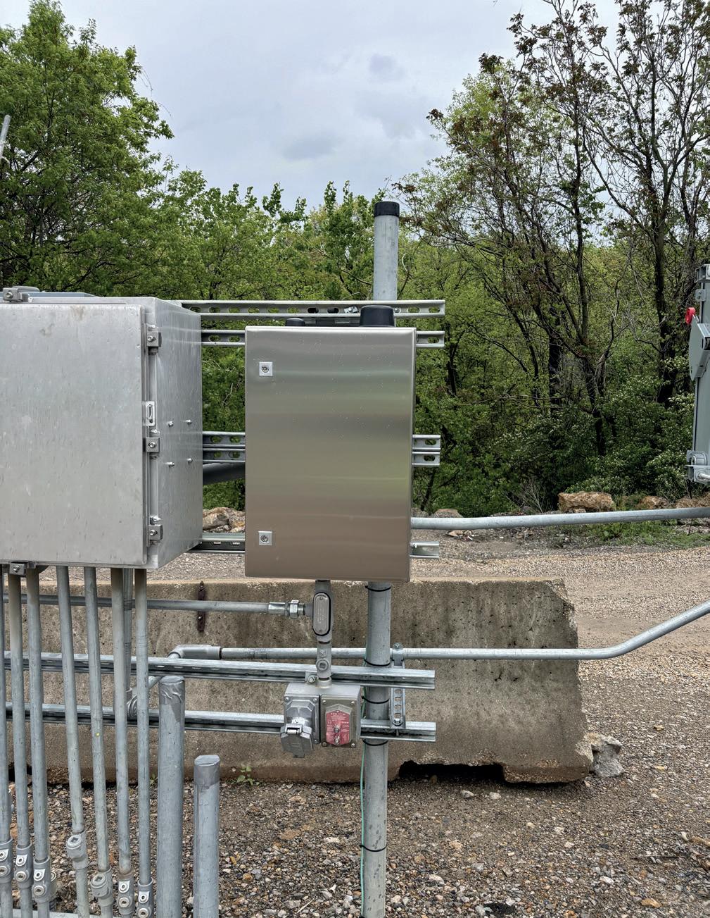
Figure 1. PipeSense’s PipeGuard system deployed on-site for a client.
Figure 2. PipeSense’s flagship advanced pipeline leak detection system PipeGuard.
Fighting back against leaks to comply with industry standards
PipeSense, the US-based pipeline leak detection technology provider, supports operators in circumnavigating industry change. With a portfolio of advanced pipeline monitoring and leak detection technologies, PipeSense empowers operators to fight against pipeline leaks while staying compliant with evolving regulatory mandates across the US.
By leveraging AI and cutting-edge machine learningbased data analysis techniques, PipeSense supports operators with pipeline integrity by quickly and accurately detecting leaks to enhance pipeline performance. Its hands-off approach ensures that pipelines remain safe and fully operational, proactively preventing, detecting, and mitigating unplanned release. This not only improves operational safety but also protects communities and the environment.
These technologies, collectively known as ‘PipeSentry’, encompass real-time advanced pipeline leak detection, realtime hydrotest leak location, pig tracking, and identifying pre-existing leaks. This collection of transformative technologies recently received an official US patent for its groundbreaking systems and methods for improved pipeline leak detection.
Specifically addressing operators’ pipeline leak detection requirements is the PipeGuard system. Leveraging the power of the Internet of Things (IoT) to bring a disruptive
Pigs Unlimited
Figure 3. PipeSense’s PipeSentry technology supports with pipeline isolation and integrity.
approach to pipeline leak detection, PipeGuard is designed to offer clients complete peace of mind. Its 24/7 monitoring capabilities ensure that any unexpected pipeline leaks, regardless of their cause, are quickly detected and precisely located. This advanced system guarantees operators can take necessary actions to quickly respond to leaks, minimising potential damage and disruption.
PipeGuard has the capability to alert operators of a leak event within 2 to 3 minutes of 20 to 50 ft along a pipeline. This is possible as user notifications are seamlessly integrated into PipeSense’s intuitive pipeline
mapping system, enabling notifications to be issued via text, email, web-based applications, and SCADA interface.
This rapid notification, along with its precision, eliminates the risk of false positives to near zero, ensuring that operators can trust the alerts they receive.
Its versatile compatibility allows it to work with any pipeline contents and configuration, even in highly variable and challenging flow regimes. Additionally, PipeGuard is adaptable for both onshore and offshore deployments, seamlessly integrating with existing systems or focusing on highly sensitive areas where required. Fully compliant with PHMSA RIN 2137-AF06, updates to 49 CFR Parts 192 and 195, and API RP 1130, PipeGuard ensures regulatory adherence while delivering unmatched performance.
NEW
High voltage Holiday Detector
With PipeGuard, clients can be confident that their pipeline operations are protected by cutting-edge technology that not only enhances safety but also ensures compliance with the latest industry regulations.
Case study: implementing solutions for industry changes
PipeSense has proven its ability to assist pipeline operators in meeting regulatory compliance. Ahead of the 1 October, 2024, deadline, a California-based pipeline operator needed to install an effective leak detection system on a section of an onshore pipeline classified as a high consequence area (HCA).
In the event of a leak, this pipeline, located in a densely populated region, posed significant risks to the operator, the community, and the environment. It was therefore crucial to deploy a system that minimised operational disruption and risk.
By utilising PipeSense’s PipeGuard system, the operator implemented a non-invasive solution that provided continuous real-time monitoring. The PipeGuard system offered immediate leak detection even during the initial embedding phase, ensuring the client received instant alerts from the outset.
Given the client’s tight deadline, the extended implementation periods typical with other leak detection systems made PipeSense the most viable option for meeting their urgent needs.
Paul Chittenden, Subsea Inspection
Technology Advisor, TSC Subsea, UK, describes carrying out an internal rigid riser inspection for bp.
Offshore platforms in the North Sea encounter unique and formidable challenges, primarily due to the harsh environmental conditions prevalent in the region. These conditions include extreme cold, high winds, and turbulent seas, all of which
Figure 1. TRITON’s bidirectional, tethered ILI pipe crawler.
significantly complicate offshore infrastructure operations and maintenance.
One of the most critical components affected by these conditions are the risers and pipelines, which are essential for transporting oil and gas from the seabed to the platform and subsequently to the shore. The region’s subsea infrastructure must endure substantial pressures from the deep waters, as well as the corrosive effects of seawater and the physical stresses caused by strong ocean currents and waves.
These challenges make rigorous inspection and maintenance critical to ensuring safety and operational integrity.
Addressing complex inspection requirements bp required an inspection of one of its risers. Initially installed as a spare, it had never been operational. As part of a new development project, bp needed to ensure the riser’s integrity before commissioning it for service. bp required a comprehensive internal inspection to confirm the riser’s suitability.
Typical pipeline and riser inspections are conducted externally, which wasn’t possible due to the duplex pipe’s complex features, including a wall thickness of 48.8 mm (1.9 in.), multiple intricate bends, the location, and surrounding obstacles.
The 110 m long riser, which included recessed welds every 10 m and featured three 3D bends, had a single entry and exit point and was filled with anti-corrosion fluid, which was maintained at elevated temperatures.
Inspection technology
TSC Subsea, known for its advanced subsea non-destructive testing (NDT) technologies and robotic deployment techniques, was called upon to tackle this intricate inspection. TSC Subsea engineers faced two primary challenges: selecting the most appropriate NDT method considering the duplex material and defect mechanisms; and developing a delivery vehicle capable of navigating vertical pipe sections with multiple 3D bends. This vehicle needed to stop precisely at areas of interest and perform 360˚ rotational scanning while maintaining constant pressure on the inspection probe.
Considering the complexity of the inspection and potential damage mechanisms, selecting the most suitable advanced NDT technologies was critical. The selected methods were alternating current field measurement (ACFM) and subsea phased array (SPA).
The utilisation of both ACFM and SPA technologies underscores the critical advantage of employing multiple NDT methods instead of relying on a single technique. Each method brings unique strengths to the table: ACFM excels in detecting and sizing surface-breaking cracks, particularly in welds; while SPA provides high-resolution volumetric inspection, capable of mapping corrosion and identifying subsurface defects with exceptional accuracy.
Integrating these complementary technologies would ensure a more comprehensive assessment of the riser’s integrity. This dual-method approach not only increased the likelihood of detecting a wider range of potential defects but also provided cross-validation of results, thereby enhancing the overall reliability and robustness of the inspection.
The delivery vehicle was TRITON, a custom-built robotic, bidirectional, tethered inline inspection (ILI) pipe crawler. This advanced robotic system was specifically designed to navigate vertical pipe sections with multiple bends and perform precise 360˚ rotations at areas of interest.
Figure 4. ACFM data showing a crack detected during the FAT.
Figure 3. TRITON tethered ILI system conducting ACFM detection capabilities.
Figure 2. TRITON, equipped with an ACFM probe, entering the test sample.
AGRULINE XXL PIPES
HDPE piping systems for horizontal directional drilling
• OUTSTANDING LIFE SPAN
• FAST AND EASY INSTALLATION
• FOR HIGH-VOLUME FLOWS
• HIGH-QUALITY MATERIALS
• EXPERTISE IN PLASTICS PROCESSING
agru Kunststofftechnik Gesellschaft m.b.H. Ing.-Pesendorfer-Strasse 31 | A-4540 Bad Hall T. +43 7258 7900 | office@agru.at | www.agru.at
ARTICULATED PIGS
Articulated pigs are typically designed to pass pipeline wye connections whilst also negotiating tight bend radius. They are also used to pass oversized features (such as ball valves, check valves or connector hubs).
This type of pig is also highly efficient in long run, dewatering/flooding and heavy duty cleaning operations as well as dual-diameter applications.
TRITON consisted of a robotic crawler with highresolution cameras to assist in navigation and perform a visual inspection. An additional module housed the ACFM array and SPA probes, followed by a technology bottle, or ‘pill’, that contained the electronic circuitry. A custom winch system was designed to manage the system’s weight and provide a fail-safe in case the crawler got stuck.
What is ACFM?
ACFM is an advanced electromagnetic inspection technology widely recognised and certified by authoritative bodies such as DNV, ABS, BV, and Lloyds. It
has a proven track record in detecting and sizing subsea surface-breaking cracks in welds, effectively replacing traditional non-computerised methods such as magnetic particle inspection (MPI).
Originally designed to assist divers in identifying and sizing fatigue cracking in jacket structures, ACFM has evolved into a recommended NDT technique for detecting and sizing subsea cracks. The technology works by introducing an alternating current into the surface of a component. When a surface-breaking crack is present, it disturbs the electromagnetic field. Advanced mathematical techniques then instantaneously convert the return signal, alerting operators to the presence of defects.
One of the major benefits of ACFM is its ability to provide immediate defect sizing and recording. Independent testing has shown that ACFM matches the performance of MPI in inspecting underwater structural welds, with significantly fewer missed or spurious signals compared to MPI and conventional eddy current testing. Additionally, ACFM requires less cleaning and generates fewer false calls, which significantly shortens inspection times and maximises inspection campaign efficiency.
What is SPA or phased array ultrasonic testing (PAUT)?
PAUT technology, initially established for highresolution corrosion mapping and crack assessment in topside operations, was extended by TSC Subsea to subsea inspections, resulting in the SPA system. This system incorporates conventional PAUT and utilises advanced applications with total focusing method (TFM) technology.
PAUT probes comprise multiple piezoelectric crystals that can independently transmit and receive signals at different times. Time delays are applied to the elements to create constructive interference of the wavefronts, allowing the ultrasonic beam to be focused at any depth in the test specimen undergoing inspection.
PAUT can simultaneously collect A-scan data at multiple angles. This unique feature produces a volumetric beam, allowing operators to distinguish between geometric reflectors and defect signals, thus increasing the likelihood of detection. Additionally, this capability improves flexibility on complex geometries, as the beam can be steered to suit the inspection requirements. In contrast, conventional ultrasound inspection methods rely on fixed-angle probes, which can be severely restrictive when inspecting parts with unfavourably oriented discontinuities.
Further advantages of phased array technology include saving data sets and utilising visual aids, making the inspection fully auditable, and allowing clients to review data sets as they are collected.
Figure 6. Full-size mock-up of the riser used to demonstrate TRITON’s navigation capabilities.
Figure 5. Test sample submerged in the water tank for SPA detection capability testing.
Factory acceptance testing and validation
To validate the inspection technology and delivery system, TSC Subsea conducted a factory acceptance test (FAT) using a purpose-built replica of the riser. This replica had the same internal diameter and 3D bends as the offshore riser. Additionally, a second duplex blind test sample, supplied by bp, contained hidden defects representative of those expected to be detected and sized during the inspection, such as surface-breaking defects at the root of the weld, gouges, and pitting.
The FAT testing phases included:
) Detection capabilities: both ACFM and SPA technologies were tested out of the water and in a purpose-built water tank to closely resemble on-site conditions. The test sample included 19 manufactured defects, all designed to test the limits of the inspection technologies. The test was successful, with all defects detected and sized within bp’s engineering tolerances.
) Navigation test: TRITON’s performance in navigating sections, bends, and executing 360˚ rotations was tested first in a dry pipe and then in a flooded pipe to simulate on-site conditions. Despite reduced visibility, the system performed flawlessly, with high-quality cameras allowing precise navigation.
Execution of the inspection campaign
Following a successful FAT, TSC Subsea deployed a team of four experts, including robotic engineers and PCN level 2 ACFM and phased array specialists, to bp’s offshore platform. Prior to conducting the inspection, function checks on all systems were carried out to ensure optimum setup.
The inspection process involved:
) ACFM inspection: a detailed 360˚ examination of all 13 welds, covering from the top toe, root, to the bottom toe, was conducted with no defects detected above the inspection reporting threshold.
) SPA inspection: TRITON employed a water wedge and a perspex wedge to determine which testing method would deliver optimum ultrasonic responses. Ultimately, the water wedge data outperformed the perspex wedge, as the latter lacked geometric reflectors. Consequently, the data from the water wedge was chosen for the SPA inspection. No defects greater than the inspection reporting threshold were detected.
Impact and future implications
The three-day offshore inspection was a resounding success, allowing bp to proceed with its development project and re-commission the riser.
This project demonstrated TSC Subsea’s commitment to addressing complex inspection requirements and its ability to adapt to challenging scenarios. By ensuring the riser’s integrity, TSC Subsea enabled bp to move forward confidently with its development project, reinforcing the role of rigorous inspection processes in safeguarding operational safety and efficiency.
The addition of the TRITON internal inspection crawler to TSC Subsea’s portfolio has opened new avenues for the internal inspection of unpiggable lines, both onshore and offshore. Following the successful development and inspection, TSC Subsea immediately completed two additional onshore scopes for other operators, demonstrating this new tethered solution’s significant demand and effectiveness in the industry.
Frank Luikinga, Project Manager from TSC Subsea, expressed profound appreciation for the collaboration: “This project was a testament to our commitment to embracing challenges and pushing the boundaries of what is achievable in subsea inspections. We look forward to future collaborations and further opportunities to demonstrate our expertise and innovation.”
Donald Macleod, bp Subsea Project Manager, added:
“The brilliant innovation and collaboration from the TSC Subsea team were fundamental to driving the success of this project from engineering to execution.”
This successful internal riser inspection highlights the critical role of advanced NDT technologies and expert engineering in ensuring the safety and reliability of offshore operations in the challenging environment of the North Sea.
Figure 7. Pipe crawler navigation test during the FAT.
Figure 8. Offshore operation showing TRITON entering the riser.
Kristen Andrew Foshaug, Chief Technology Officer, Connector Subsea Solutions,
discusses solutions for enhancing deepwater and diverless pipeline repairs, involving minimised direct connection time between the pipeline and vessel, fewer hydraulic leak points, and a quick installation process.
ipelines serve as the backbone of our energy supply, ensuring a consistent and reliable provision of energy. Beyond their fundamental role in resource transportation, pipelines have gained growing political significance and, unfortunately, have become targets of sabotage.
Various incidents can compromise the integrity of a pipeline system, including degradation mechanisms and external events. Examples encompass internal and external metal loss due to corrosion, fatigue life depletion or undesigned movement/strain caused by an unstable seabed condition. Additionally, events such as anchor hooking, trawl gear interference, and objects dropped from the surface can impact the expected life of subsea assets.
For subsea pipeline repair operations, the industry increasingly turns to diverless technologies, driven by the need for enhanced safety, cost savings, and deeper operational capabilities. These technologies eliminate the significant
risks associated with human diving, offering greater efficiency and quicker deployment, are less affected by environmental conditions, align with regulatory demands for safer operations and expand their use even in shallower waters in addition to traditional deepwater applications.
Since the early 1980s, Connector Subsea Solutions (CSS) has pioneered energy security via pipeline repair, developing MORGRIP® pipeline repair products suitable for both shallow and diverless installations. Several design iterations of the MORGRIP repair clamp range over the years has led to the latest advancements in MORGRIP Deepwater Repair Clamps; engineered to meet the rising demand for diverless and deepwater repair and mitigate the challenges associated during deployment, including decoupling deepwater repair equipment from installation vessels and activating the equipment using hydraulics.
Typical subsea pipeline repair operations using connectors and clamps
When a pipeline anomaly is detected, the first step is to assess the damage and isolate the affected section of the pipeline. This is achieved through inspection methods such as visual checks, ultrasonic testing or the use of smart pigs (pipeline inspection gauges).
For the most comprehensive damages, a whole section of the pipeline needs to be cut and replaced. The areas to be cut are carefully marked to ensure the cuts are made well beyond the damaged area, including any potentially weakened sections. The removed section is typically inspected further to understand the extent of the damage and to plan for future preventive measures.
During the initial pipe fabrication for the pipeline delivery project, a few extra pipe sections are typically manufactured and stored for future contingency measures. If not, replacement sections are available from the original pipe manufacture; a new spool is fabricated to match the dimensions of the removed section. This replacement section is made from materials that are compatible with the existing pipeline in terms of strength, corrosion resistance and pressure handling.
Joining the new spool to the existing pipeline is typically done either by welding in a hyperbaric chamber or with a mechanical pipeline repair connector which both seals and grips the pipe it connects onto. Both welding and connector repairs require extensive systems including various tools used for pipeline coating removal, pipe handling and manipulation and total system alignment, all of which reside within CSS’ capabilities and solutions portfolio.
For less extensive damages like leaks or dents, pipeline repair clamps are commonly utilised. These clamps consist of two half shells that encircle the compromised section of the pipeline. They are placed around the pipe and fastened together, usually with bolts. The clamps may serve to reinstate or improve the structural capacity of the damaged pipe or seal the damaged area, and they can also be designed to offer both reinforcement and sealing capabilities.
Rising demand for diverless and deepwater pipeline repair
The 1970s marked the beginning of widespread adoption of ROVs in the oil and gas industry. The technology became essential
Figure 1. 42 in. MORGRIP® subsea pipeline repair connector.
for subsea exploration and construction as offshore operations moved into deeper waters where traditional diving methods were not feasible.
The oil and gas industry is increasingly adopting diverless methods for subsea equipment, driven by the need for enhanced safety, cost reductions and the ability to operate in deeper waters.
Diving operations, especially in harsh or deepwater environments, pose significant risks to human divers including decompression sickness, underwater hazards and the potential for accidents. Diverless technologies and specialised systems eliminate these risks by taking human divers out of the equation.
Operations without divers usually save money over time because they remove the necessity for extensive dive support ships, specialised diver gear and the intricate coordination required for human diving teams. Technologies that don’t need divers can also be deployed quicker and reduce potential delays since they are not as affected by weather conditions and other issues that can hinder human underwater operations.
Regulatory bodies and operators are increasingly focused on safety, and diverless technologies help companies meet these requirements by reducing the risk of accidents. Additionally, shallow water operations, typically performed by divers, are now being performed with diverless technologies previously applied in deepwater only.
Deepwater pipeline repairs are among the toughest tasks in the offshore sector, but the market is calling for solutions that are cost-efficient, simple, and reliable.
Principles in diverless and deepwater pipeline repair
Decoupling
It is essential to limit the length of time a pipeline repair clamp stays directly connected to an installation vessel via a crane during setup. Situations like drive-off/drift-off events or malfunctions in a crane’s heave compensation system pose
serious risks and could lead to further damage to the pipeline under repair. The most secure method involves separating the lifting operation from the pipeline repair operation, usually this requires sophisticated installation tools. This decoupling technique allows the repair equipment to be lowered to the seabed and then uncoupled from the lifting gear. After this, the repair installation can proceed by engaging the necessary functions through the installation tooling.
Hydraulics
The most common way of activating or invoking the different functions involved in the repair process is with hydraulics. Hydraulic hot stabs are specialised tools used in subsea operations to provide a temporary hydraulic connection between two points, typically between an ROV and subsea equipment. The hot stabs are crucial in underwater maintenance, repair and installation tasks where hydraulic power needs to be transferred quickly and safely without permanently connecting the systems.
The best practice for any pressurised system involves minimising the number of potential leak points, usually by reducing the use of flanges, fittings, and connections in favour of welds. As a result, welded small-bore tubing is the favoured network design for distributing hydraulics in deepwater tools. However, for some subsea equipment with movable components, this approach is not always feasible, as flexible hoses are required for dynamic applications.
The flexible hoses are equipped with fittings, but the connections at the junctions between fittings have frequently become weak points in hydraulic systems. In some cases, a leak from a fitting can threaten the functionality of the repair equipment and potentially cause damage to the pipeline under repair. Limiting the number of hoses and fittings is therefore good practice to ensure robust subsea operation.
Deepwater repair clamps
The MORGRIP pipeline repair product range was originally developed in the 1980s. The first offshore installation of a MORGRIP was in 1988 and the first installation without diver assistance was in 1996. Initially designed for pipeline repair, these products have also been applied to vertical riser systems and extended to neighbouring subsea infrastructure such as Christmas trees and umbilical termination units.
The most recent addition to the MORGRIP family of products is a pipeline repair clamp which has been optimised for deepwater and diverless operations, and is exemplified through a recent delivery project with the following characteristics:
) Pipeline outer diameter: ø 32 in.
) Pipeline transport content: natural gas.
) Maximum installation depth: 2200 m (7218 ft).
) Clamp test pressure: 403 barg.
) Maximum installation angle: 30˚.
Figure 4. MORGRIP Deepwater Repair Clamp and installation tool tested at 30° installation angle.
GripTight ® Test & Isolation Plugs
GripTight Test and Isolation Plugs have been installed countless times in a wide range of applications. Their patented designs combined with hardened components and single-body, uninterrupted seals make for field performance that’s second to none.
Whether you’re testing open end pipe, systems terminating in long radius elbows, testing flange welds or isolating lines you can count on the GripTight Family of Test & Isolation Plugs from Curtiss-Wright to perform above expectations, test after test.
• OD and ID solutions available
• Patented gripper design for increased safety in high-pressure applications
• Eliminates welding end caps for pressure testing pipe spools and piping systems
• Test flange-to-pipe welds without pressurizing entire systems
• Isolate & monitor upstream pressure and vapors during hot work
• Standard pressure ratings up to 15,000 PsiG (1034 BarG)
• ASME PCC-2 Type I, III & IV Testing Devices
877.503.0768
The traditional approach to install pipeline repair clamps is to bolt the two half shells together. In dry/topside applications this involves closing the two half shells around the pipeline, threading the stud bolts onto the nuts and using a tool to apply torque to the bolts, thereby pre-tensioning the two half shells towards each other. Threading bolts subsea by ROV is not advisable due to the significant risk of cross threading. This risk can be mitigated by using special nuts with a ratchet function which allow for bolts being inserted onto a nut without rotating either of the components. However, application of torque gives a high scatter in minimum and maximum bolt load and is very time-consuming for a connection made up of many bolts.
Hydraulic bolt tensioners work by applying direct axial force to a bolt by use of a hydraulic piston which stretches the bolt to achieve a desired level of tension without relying on torque. Once the desired tension is achieved, the locking nut is wound down. This process ensures a more accurate and consistent bolt load compared to traditional torque wrenches. For deepwater applications, a motor is included to the system which allows for nut-running by application of hydraulics rather than a rotary motion from a diver or ROV. An example of such a clamp is depicted in Figure 2. The main drawback with this approach is that many leak paths are introduced through hydraulic connections to each hydraulic bolt tensioner and motor controlling the nut-running.
MORGRIP Deepwater Repair
Clamps use neither traditional individual torque nor tension methods. Rather, the clamp employs a patented system featuring two large cylinders and a series of wedges that simultaneously apply tension to all bolts. Additionally, it utilises hydraulically operated split nuts to open and close all nuts at once. A simplified illustration of the MORGRIP Deepwater Repair Clamp can be seen in Figure 3.
Repair clamps are available with varying levels of structural reinforcement. This particular clamp is engineered and sized to withstand the forces associated with a completely severed pipeline. Its structural integrity was confirmed during testing, which included a pressure test with fully severed pipe sections placed within the clamp.
Due to the exceptionally soft soil conditions in this particular instance, utilising the seabed as a landing platform for the clamp was not feasible. With a maximum pipeline slope of 30˚, the only viable solution was to use an installation tool that securely grips the pipeline. This solution does not fully decouple the vessel crane and the pipeline but minimises the time in which they are directly connected in a ‘land, grip and release’ function of the installation tool.
MORGRIP Deepwater Repair
Clamps exemplify the ideal solution for enhancing deepwater or diverless pipeline repairs due to their simple, reliable, and rapid activation. This effectiveness is a result of the minimised direct connection time between the pipeline and vessel during installation, fewer hydraulic leak points, and very quick installation process.
Jun Zhang, Atmos International, considers the growing significance of produced water pipeline leak detection in gathering networks.
he oil and gas industry continues to boom with major projects under development across the world.1 In North America for example, this is in part due to factors like the shale boom, which has resulted in oil producers needing to expand gathering pipeline networks by hundreds of miles to keep up with demand.2 Oil and gas is similarly booming in Africa, Asia and the Middle East due to the regions’ abundance of reserves.3,4,5
Increased production of oil and gas worldwide brings with it an increase in gathering networks.
Gathering networks are a crucial component of oil and gas production because they transport hydrocarbons between the production site, processing facilities and to end customers. Gathering pipelines typically operate in multiphase and carry a mix of products before they are separated, such as crude oil, natural gas, natural gas liquids, impurities like sulfur compounds and other trace elements and sediments and solids like sand and clay. This article focuses on produced water, which is generated in large amounts during the oil and gas extraction process and in some cases is transported on a journey that includes upstream, midstream and downstream sectors.
As the global oil and gas industry continues to grow, so will the amounts of produced water, with 2020 marking the first year that the annual global quantity of produced water from oil and gas operations exceeded 240 billion bbls. 6
While produced water sounds harmless on the surface, failure to appropriately dispose of or reuse produced water can have severe environmental impacts. 7 This article discusses the significance of pipeline leak detection for produced water management.
What is produced water?
Produced water or ‘brine’ is a byproduct of the oil and gas extraction process and it typically takes a brackish or saline water form when it is collected. There are many sources of produced water too. For example, most oil and gas bearing rocks contain formation water, which is collected when oil and gas reservoirs are mined. 8
Produced water is also created during water injection, which is when oil recovery involves forcing oil towards a well for extraction by injecting water. 9 The injected water returning to the surface takes on the form of produced water.
Water vapour present in the production of natural gas can also condense out of the gas stream due to pressure and temperature changes, becoming produced water. A final example source of produced water occurs during fracking operations. Similar to water injection in the oil industry, fracking involves injecting water mixed with chemicals into a well to fracture the rock and release oil and gas, but the water returning to the surface becomes flowback water. 10
Managing produced water transportation
Pipelines are the safest means of transporting any fluid, which is why produced water upstream is typically transported via pipelines from wellheads to central processing facilities to remove hydrocarbons and solids. Pipelines are also crucial in the midstream transportation of produced water for further processing so it can be purified for disposal or reuse. While being the safest means of transporting produced water, a pipeline leak can still have severe consequences.
The significance of pipeline leak detection
Environmental risks
Brine (produced water) is a saturated solution of dissolved salts, oil, and drilling chemicals that exhibits elevated levels of total dissolved solids (TDS), electrical conductivity (EC), and sodium adsorption ratio (SAR). Environmental exposure to brine through accidental releases or abandoned evaporation pits can have severe deleterious effects on soil quality and vegetative health. For example, the concentrations of sodium (Na) within brine can invoke swelling and dispersion of soil particles, and the elevated EC levels most often kill salt-sensitive agricultural crops and native plants and vegetation. 11
Produced water leakage occurring offshore can impact water quality by introducing contaminants such as biocides, hydrocarbons, metals, salts and more into the environment. These can affect marine life by altering oxygen, pH, salinity and temperature levels in the environment and impact the survival of marine organisms. If the leak occurs in a water source used for drinking, irrigation or recreation, produced water can also be hazardous to human health.
Wasting resources
Some regions with high reserves of oil and gas face water scarcity. For example,
Figure 1. The new algorithm alarmed for a small product loss on a UK pipeline company’s network (red bar in the top chart indicating leak/theft alarm).
15 of the 20 most water scarce countries are in the Middle East and North Africa, but these are also two regions which use water to produce oil and gas. Produced water pipeline leaks in regions where there are water scarcity issues can have severe consequences on water supply and management.
Considering the climate
Produced water can contain traces of dissolved gases, such as carbon dioxide, hydrogen sulfide and methane. These are greenhouse gases and contribute towards global warming if they are released into the atmosphere.
Regulatory requirements
Depending on the region an oil and gas company operates in, produced water leakage can risk violating regulatory requirements related to spill prevention and response.
To avoid the environmental, financial, reputational and social risks associated with produced water leakage, oil and gas companies should consider installing a leak detection system.
Produced water leak detection
A pipeline leak detection system that optimises sensitivity and accuracy on the most complex pipelines, such as gathering networks, is crucial to minimising the potential damage associated with a produced water leak.
Leak detection systems comprising of advanced statistical analysis algorithms are proven to be the most effective approach to leak detection in gathering networks.
Algorithms like the sequential probability ratio test can analyse pressure and flow to optimise leak detection using data from SCADA, DCS, PLC or RTU systems. Selftrained filters in some leak detection software can also compensate for measurement errors to maximise performance. Recent algorithm updates can also improve leak detection in high consequence areas, where gathering lines transporting produced water are typically located.
One example of an upgraded leak detection algorithm relates to onset leak detection. This method can be used as an additional leak detection alarm to provide an added level of protection.
On a produced water pipeline, this means high sensitivity can be achieved without increased false alarms because transients and density changes are identified automatically.
Case study: produced water gathering network in the Americas
A leak occurred in the well node of a customer’s produced water network which has multiple inlets and outlets and transports produced water.
The leak began as a small leak and caused a rupture when the customer started the pumps at one of their wells. The leak was detected quickly using a statistical corrected volume balance leak detection system which was able to identify that the pipeline’s flow was displaced.
The system was able to alarm within seven minutes, with the total volume spilled being 170 m 3 , and the failure point was roughly 14 in. long (Figure 2).
Leak detection is key to minimising produced water pipeline risks
Produced water pipeline leaks can have serious consequences including threats to human safety, damage to the environment, property and reputation, not to mention the financial loss through fines and clean-up costs. The installation of a suitable leak detection system can detect produced water leaks quickly, locate them accurately, issue minimal false alarms, be easy to retrofit, work effectively under all operating conditions and use sensors with high reliability and low maintenance.
Figure 2. The failure point of this customer’s pipeline was roughly 14 in. long.
Manuel Alonso and Hans Overdijkink, Intero Integrity Services B.V., Netherlands, present an innovative pipeline inspection technique for a challenging manifold inspection.
TACKLINGCOMPLEXCHALLENGES
ntero Integrity Services B.V. was tasked with inspecting a 36 in. pipeline in 2023, which included a challenging manifold inspection. The challenge stemmed from a manifold featuring six large-diameter take-offs, posing a significant obstacle for standard bi-directional pigs and inspection tools.
WITH A DUAL-TOOLASSEMBLY
To address this, Intero proposed a multistage project plan, including:
) Paper/digital feasibility assessment.
) Proof of concept at Intero’s base in the Netherlands.
) Actual ultrasonic inspection of the pipeline including the manifold.
Project background
In August 2017, Intero conducted an ultrasonic inspection of a segment of the pipeline, stretching from the launching point to the manifold area. Initially, it was assumed that the inspection wouldn’t extend beyond this point, covering approximately 800 m. Nevertheless, this limited ultrasonic inspection yielded valuable data, offering essential insights for the client.
Recognising the significance of this data and looking ahead to the future, the client presented Intero with a challenge: to carry out an ultrasonic inspection of the entire pipeline during the next scheduled shutdown. With a commitment to excellence and the right team in place, along with the necessary investments, Intero took on the challenge, embarking on the design of the tool and operation.
The inspection technology
The Pipeline Surveyor system employs a contact-free ultrasonic measuring head for maximum flexibility, capable of scanning the entire pipe wall surface. It can handle various pipeline features such as dual diameters, mitered bends, full-bore unbarred tee pieces, and single entry configurations using regular, high, and ultra-high resolutions. The Pipeline Surveyor is designed for inspecting ‘unpiggable’ or challenging pipelines ranging from 3 - 64 in., located anywhere in the world, from subsea offshore to remote areas.
The Pipeline Surveyor can be equipped with different measuring heads:
Matrix
) Multiple transducers evenly distributed over the tool’s circumference.
) High-speed operation.
Helix
) Rotating mirror covering the entire pipe wall.
) Flexibility to increase resolution and measurement grid.
Centrix
) Rotating mirror covering the entire pipe wall.
) Flexibility to increase resolution and measurement grid.
) Phased array technology to increase sensitivity.
The paper/digital feasability test
The project’s challenge involved customising an inspection solution capable of navigating 1.5D bends and varying distances
Figure 1. Loading of bidi and inspection tool during test.
Figure 2. Inspection tool with protective nose.
ramming
between take-offs. The optimal solution involved creating a linkage between a bidirectional pig and the inspection tool. This design ensures that if one of them loses traction, the other can provide the necessary traction for the dual-body system.
Simulation
To start the process, a 3D model of the manifold and take offs was drawn.
In that 3D model a bidi and inspection tool assembly were placed to simulate a run and observe in which scenarios a bypass would be created.
The distance between the bidi and inspection tool was carefully adjusted to create a situation in which bypass would never occur on both pigs at the same time.
Detailed engineering: 3D design and 2D drawings
After a successful simulation, the next step involved detailed engineering of the inspection tool and bidirectional pig. Key considerations included ensuring all components could withstand the pushing and pulling forces and safeguarding the steel cable from damage.
Proof of concept Test
To minimise the risk of a successful inspection, a test was conducted at Intero’s facilities in Tricht, the Netherlands. A custom 36 in. spool with 10 in. take-offs was fabricated to partially replicate the site conditions. Additionally, the existing 36 in. pig traps were extended to accommodate the launch and reception of two pigs simultaneously.
Results of the test
The concept proved successful, requiring only minor adjustments for on-site assembly. Furthermore, a specialised ‘rescue pig’ was procured to address cable breakage scenarios. To have a solution prepared just in case, a special foam pig was ordered.
Execution
The project commenced in August 2023 at the customer’s site, beginning with safety training and site access. This section outlines the on-site execution and the project’s results.
Purpose of the inspection
The inspection’s primary purpose was to assess the pipeline’s integrity. The pipeline, with a diameter of 36 in. and a length of 4020 m, was previously inspected, and the customer requested a fitness for purpose (FFP) assessment and corrosion growth evaluation.
Key pipeline characteristics included:
• Diameter: 36 in.
• Length: 4020 m.
• Wall Thicknesses: 12.7 mm, 14.3 mm, 15.9 mm, 19.1 mm.
Mechanical preparation and set up
Days before the work on-site was executed, the needed materials for the job were prepared (inspection tool, launcher/receiver, hoses etc.) and transported to the customer’s site.
Once on-site, after the safety training and risk assessment the equipment was unloaded and connected to the customer’s system.
Figure 3. Finalising the successful ultrasonic inspection of challenging pipelines.
Determining markers/GPS coordinates
To ensure accurate GPS coordinates of pipeline features and anomalies, the inspection tool was equipped with a gyroscope. The GPS coordinates of markers were precisely measured to enhance the accuracy of GPS data.
Cleaning/gauging
A progressive cleaning programme, developed through collaboration between the customer and Intero, was
implemented. The challenge involved removing debris from the pipeline without getting stuck in the T-pieces.
After several brush pigs were run, two runs with the dual-body system were executed to confirm the line’s cleanliness.
Inspection
During the cleaning process, a sample of the product was taken for calibration of the high-resolution ultrasonic measuring head, which was conducted to prepare for inspections in crude. Once the pipeline was deemed clean, the inspection tool was assembled and made ready for the inspection. Just before launching the inspection tool, the fibre optic connection for online data was established. The high-resolution inspection, including passage through the T-pieces, was completed within 20 hours (average 262 mph), and data collection was successful.
Ultrasonic results
No major anomalies were detected, and the pipeline was found to be in good condition.
Conclusion
In July 2023, Intero successfully executed the anticipated inspection, meeting the client’s expectations and garnering their full satisfaction. This accomplishment not only ensured the integrity of their critical pipeline but also provided a robust solution for its future maintenance and safety.
Inspecting ‘non-piggable’ or challenging pipelines is possible with the correct approach and technical expertise to reduce the risk. It is critical to follow a multi-step approach which includes: a paper exercise, engineering, mechanical testing of the engineered solution, and finally the work on-site.
Note
This article is based on a presentation given at the 2024 Pipeline Technology Conference (ISSN 2510-6716) www.pipelineconference.com/conferences.
Maja Hornig, TIB Chemicals, answers the question of whether it is possible for one single coating to meet the extensive range of requirements and standards for pipelines. he degradation and corrosion of materials greatly affects the life time of pipeline assets. To extend their life cycle, installations must be protected from the effects of corrosion. Long lasting corrosion protection is hence one of the most crucial issues in the entire pipeline industry. Along with excellent anti corrosion properties, protective coatings for pipelines must fulfill
Figure 1. Protegol 32-60 being used as the interior lining for a buried pipeline.
international standards to document and ensure the safe operation of conduits and fittings and to protect these assets.
But is it possible for one single coating to meet the extensive range of requirements and standards for oil, gas and water pipelines simultaneously? And if that coating
was additionally easy to use and fit for many application methods? It turns out it is indeed possible.
Outline of coating requirements
The objective was the development of an extremely compatible multi-component liquid (MCL) coating based on aromatic isocyanate and advanced polyols, 100 % solids, fit for direct-to-steel single-coat application and with good adhesion to parent coating like polyethylene, polypropylene or epoxy.
Four major industry standards were identified as most essential for pipes and fittings, responding to requirements of the oil and gas and the water industries: DIN EN 10290, 1 ISO 21809-3, 2 AWWA C222-18, 3 and DIN 3476-2. 4 Clearly, to ensure long term protection against chemical and mechanical attack, the focus needed to be on vital chemical-physical parameters such as excellent adhesion, high impact resistance and low cathodic disbondment values.
Mixing-related failures being a major issue in the industry, a 1:1 mixing ratio would clearly help minimising that risk to almost zero. Moreover, the all-in-one solution should serve global field projects as well as local stationary application, allowing a clean and quick application, and early testing and installation.
The development process
To achieve the desired volumetric mixing ratio of 1:1, it was first important to consider the technical requirements, like ideal density, viscosity and other values of both, polyol (resin, component A) and isocyanate (hardener, component B).
Values of the solvent-free formulation have finally been recorded with a favourable low density of 1.2 g/cm 3 (at 23°C) for both components A and B, resin and hardener, both 0% volatile organic compound (VOC). Benefits of the low and identical density are easy handling and mixing, volumetric and gravimetric mixing ratio both confirming 1:1. That perfect mixing ratio moreover provides a wider tolerance for spray application gear. Assuming a spray equipment’s mixing tolerance of 5%, the 1:1 ratio is the most convenient.
Although viscosities of comp. A and B are slightly different at 25°C, 2600 mPa*s for comp. A and 800 mPa*s for comp. B, almost the same viscosity is obtained by proper heating to specific application temperature, usually up to 80°C if necessary.
The combination of highly reactive raw materials and automated application process allows for quick coating, curing and inspection as well as commissioning in shop and field. Potlife results in 25 sec. at 35°C and 10 sec. at 60°C, product can be touch dry after approximately 5 min. and stackable after approximately 10 min., solely by ambient friendly self-curing without pre or post heating.
During the development process, we constantly evaluated how the behaviour of materials and coatings is affected by artificially generated atmospheres and carried out measurements of corrosion behaviour
Figure 2. Protegol 32-60 applied to the exterior of a pipeline.
Figure 3. Protegol 32-60 in cartridge form, being applied to section of a gas pipeline, by an air assisted pneumatic pistol.
according to the targeted international standards, analysing the protection capacity of the coating against corrosion.
Final tests prove that the developed formulation provides long term protection and actually simultaneously complies with four of the most important international standards of the pipeline industry: DIN EN 10290, ISO 21809-3, AWWA C222-18 and DIN 3476-2.
Ease of application
Modern coating products must offer an easy application for the painters, in terms of safety at work and time saving properties. The 1:1 mixing ratio of the newly developed quick coating, permits the application by automated airless hot spray equipment together with a fusion or impingement gun spray head, where MCL gets mixed straight inside the mixing chamber. In contrast to other liquid coatings, a static mixer is avoided and no solvents required for equipment cleaning, compressed air doing that job, providing advantage for the applicator and the ambience.
We subsequently advanced one step further. Application should also be easy and consistent for remote jobs and hard-to-access areas, where heavy spray equipment could possibly not be an option, but medium or separated surface needs to be protected with consistent high quality coatings. A typical scenario for this would be girth weld coating, or soil-air transition e.g. on compressor stations.
Once more, due to the 1:1 mixing ratio and the advantageous density, the new product could also be applied by portable air-assisted spray device, pre
confectioned in twin-cartridges that could be heated on site by existing heat sources. By warming up the components to max. 45°C the applicator can influence the curing time of components. The pneumatic gun only requires very low investment.
To finally complete the system, coupled 50 ml cartridges are the perfect match for touch up areas of the size the palm of a hand, that may occur when conducting destructive testing such as pull-off (dolly) adhesion testing. Instant curing is given even at 23°C material temperature.
Fit for all and easy to use
The developed 100% solids polyurethane coating with a mixing ratio of 1:1 is the most versatile and reliable solution, suitable for use under workshop and field conditions with optimal corrosion protection for all types and sizes of buried pipes and structures.
Due to its excellent physical properties and versatility, the coating developed is an all-round outstanding solution for new construction, maintenance and rehabilitation or field joint protection. It has been proven to serve for the whole network including pipes, bends, fittings and valves. It convinces for both coating and lining application, providing a long-lasting and cost effective solution from spot sections to large scale pipeline projects.
) Good for protection: provides excellent long lasting protection against corrosion and chemical attack.
) Good for certifications: meets international standards DIN EN 10290, DIN EN ISO 21809-3, AWWA C222-18, DIN 3476-2.
) Good for applicators:
• No mixing failures – 1:1 mixing ratio.
• No interlayer failures – high-built single coat direct to metal.
• Choice of easy and consistent application – heated plural component spray or pre-confectioned cartridge.
) Good to our environment: solvent free formulation and application process.
) Good to project economies: quick inspection and commissioning.
The outcome is a 100% solids high-built polyurethane that makes the coating job safe and easy for the applicator, meets four of the most important international standards in the industry and significantly extends the operational life time of the project.
References
1. DIN EN 10290: Steel tubes and fittings for onshore and offshore pipelines, External liquid polyurethane and polyurethane-modified coatings
2. ISO 21809-3: Petroleum and natural gas industries – External coatings for buried und submerges pipelines used in pipeline transportation systems – Part 3: Field joint coating, Chapter 18
3. AWWA C222-18: Polyurethane Coatings and Linings for Steel Water Pipe and Fittings
4. DIN 3476-2: Valves – Requirements and tests – Part 2: corrosion protection by duromer thick coatings
Figure 4. Field joints are also possible to coat using the all-in-one Protegol coating system.
John Barbera, Barbco Inc. and Drake Barbera, BGN Trenchless Consulting, USA, outline trenchless technology methods and applications in oil and gas pipelines, with a focus on auger boring and cradle boring machines.
In the modern era of infrastructure development, the need for efficient and minimally invasive methods to lay pipelines has become increasingly evident. Traditional trenching methods, while effective, often involve extensive surface disruption, environmental impact, and significant costs. To address these challenges, trenchless technology has emerged as a transformative solution.
Figure 1. Barbco 48-750 pushing a 48 in. double knuckle steering head.
Among the various trenchless methods, auger boring and cradle boring stand out for their effectiveness in the installation of oil and gas pipelines. This article delves into the principles, advantages, and applications of these technologies, highlighting their role in advancing pipeline construction while minimising surface disruption.
Understanding trenchless technology
Trenchless technology refers to a suite of techniques for installing and repairing pipelines, or utilities without the need for extensive digging or surface disruption. These methods are particularly valuable in urban areas, where traditional trenching could lead to significant traffic delays, environmental damage, and increased costs. The primary trenchless technologies include auger boring, horizontal directional drilling (HDD), guided boring, and tunnelling. Each method offers unique advantages and is suited to different types of projects and soil conditions.
Auger boring machines (ABM)
Principles and operation
Auger boring is a trenchless method used to install pipelines by boring a hole through the ground while simultaneously advancing casing. The process involves several key components: the boring machine, auger, cutting head, and the casing pipe. The boring machine, typically equipped with a powerful rotary drive, rotates the auger while trusting forward to advance through the soil. As the auger rotates, it excavates the soil to the entrance pit, where it can then be removed. Simultaneously, a casing pipe is pushed into the borehole, which provides a safe support under roadways during installation, and a conduit for the pipeline to be installed.
Advantages
) Minimal surface disruption: auger boring requires only relatively small entry and exit pits, reducing the impact on surface activities and minimising restoration efforts.
) Cost-effective: compared to traditional trenching, auger boring can be more cost-effective, particularly in areas with existing infrastructure.
) Versatility: with proper tooling, auger boring is suitable for a wide range of soil conditions and can handle various pipeline sizes and materials.
) Precision: the method coupled with guidance techniques allows for the most precise control over the grade, alignment and depth of the crossing, ensuring accurate pipeline installation.
Applications
Auger boring is commonly used for installing pipelines under roads, railways, and other obstacles where traditional trenching would be impractical. It is particularly effective in urban environments where surface disruption needs to be
minimised. Additionally, with proper tooling, auger boring is well suited for most all soil types, and in areas where minimal environmental impact is a priority.
Cradle boring machines (CBM)
Principles and operation
Cradle boring is a specialised trenchless method used to efficiently install pipelines. The technique involves the use of a cradle boring machine, sideboom dozer, excavator, and an anchor point. The CBM features a cradle-like support structure to stabilise the CBM, and the pipeline being installed. The cradle provides additional support to the boring machine and helps distribute the weight, and thrust load evenly.
The operation begins with the setup of the cradle boring machine being suspended at the entry point. The machine then bores through the soil while simultaneously pushing the casing pipe forward using a winch system hooked up to an anchor point buried crossway over the top of the bore entrance. The cradle system ensures that the CBM remains stable during boring operation.
Advantages
) Improved efficiency: the CBM allows contractors to have increased efficiency by not needing to devote resources to pit grading, and shoring trenches.
) Minimal surface disruption: similar to auger boring, cradle boring only requires a relatively small starter trench, which saves time and labour compared to traditional boring, and minimises restoration efforts.
) Safe practice: cradle boring has been around for over 50 years, but it’s made significant improvements since its inception. Today, all CBMs are equipped with stateof-the-art safety features, such as hydraulic clutches, load sensing circuits, and most importantly, Barbco’s CBMs can be fully remote-control operated; taking the operator off the machine for optimal safety.
Applications
Cradle boring is particularly useful when time is of the essence. CBMs are engineered for open-trench, crosscountry pipeline road crossings, handling the installation of large steel casings up to 56 in. in diameter. They can also place casing sections as long as 140 ft in a single pass, without the need for extra track like a traditional auger boring machine.
Comparing auger boring and cradle boring
Both auger boring and cradle boring machines offer distinct advantages for pipeline installation, and the choice between them depends on several factors, including project timeline, soil conditions, project requirements, and budget constraints.
) Timeline: long-distance projects can in some cases require over 30 bores spanning over 20 - 50 miles. To
ensure a swift return on the infrastructure investment to the owner, these tasks must be expedited efficiently, and can be done so using a CBM.
) Soil conditions: auger boring is effective in a variety of soil types, including hard rock, while cradle boring requires displaceable ground. The choice of methodology should be based on a thorough assessment of the soil conditions at the project site.
) Precision and stability: auger boring offers enhanced stability and precision, making it suitable for challenging conditions where additional support and precision is needed. Cradle boring provides good accuracy based on the operational team’s experience.
) Surface impact: both methods minimise surface disruption, and remove the need to leave an unsupported hole under any crossing, compared to
Figure 2. Barbco 30RCBM being demonstrated for contractors.
ADVERTISERS’ DIRECTORY
traditional trenching and HDD. Cradle boring is generally more suited for projects with less challenging soil conditions. Auger boring, with its enhanced stability, and thrust capability, is ideal for projects in sensitive or high-risk areas, as it can be highly accurate when used in conjunction with guidance systems.
Case studies and examples
Several successful projects illustrate the benefits of auger boring and cradle boring in pipeline construction.
) Auger boring in urban areas: in recent urban pipeline installation projects, auger boring was used to install gas pipelines beneath a busy street. The method allowed for minimal disruption to traffic and local businesses, demonstrating its effectiveness in high-density environments.
) Cradle boring under time constraints: many major pipeline infrastructure projects have been significantly sped up by utilising a CBM. With the ability to push large sections of casing at once, in some cases, contractors have experienced increases in production up to 3x compared to traditional track levelled auger boring.
Future trends and innovations
As technology continues to advance, both auger boring and cradle boring methods are evolving. Innovations in machine design, materials, and automation are enhancing the efficiency, accuracy, and safety of these trenchless methods. For example, advancements in machine control systems and real-time monitoring are improving the precision of borehole alignment, grade control, and safety.
Additionally, the integration of data analytics and predictive maintenance is expected to further enhance the performance and reliability of trenchless technologies. These innovations will contribute to the continued growth and adoption of auger boring and cradle boring in the oil and gas pipeline industry.
Conclusion
Trenchless technology, particularly cradle boring and auger boring, represents a significant advancement in pipeline construction. By optimising efficiency, minimising surface disruption and addressing challenging soil conditions, these methods offer efficient solutions for installing oil and gas pipelines. As technology continues to evolve, the benefits of trenchless methods are likely to expand, further enhancing their role in infrastructure development and contributing to more sustainable and less disruptive construction practices.
References 1. “Cradle Boring Makes a Comeback.” Undergroundinfrastructure.com, 2016, undergroundinfrastructure.com/magazine/2016/may-2016-vol-71-no-5/ features/cradle-boring-makes-a-comeback
API is now offering assessments for pipeline contractors and service providers to evaluate the health of their current safety management systems (SMS), help mature their safety programs and cultivate a collaborative safety culture between pipeline contractors and operators.
Conducted by experienced assessors with expert knowledge of industry good practices, these scalable assessments can take place at any stage of a contractor’s SMS implementation to track safety performance and foster continuous improvement.