
5 minute read
Global coverage of the cement industry


• International cement news
• Regional reports
• Market analysis
• Event previews and reviews
• In-depth technical articles
• In-depth regional analysis by key players in the industry
• Comprehensive technical reviews on all aspects of cement production, from the quarry face to despatch f Massive sample reduction. f Fine grinding of sample. f Determine the loss on ignition of each sample as per EN 196-2 test method. f Prepare fused beads as per EN 196-2 procedure for fused beads of the constituents and mix, present these to the spectrometer. Use the calibration curve that was set up with the CRM Fusions. f Calculate the results on a moisture-free basis. f Input the moisture-free results obtained from the fusion XRF results. f Run the constituent resolving Original Multiple Mix Resolution Vs 1.
Drying temperatures are chosen according to the sample type.
Software program used for the mix resolution Table 10 contains the concrete analysis. Tables 1 – 9 show the XRF results of the individual constituents and the concrete.
Case study
A customer-compliant concrete cube mix resolution was received containing: f Cement. f Fly ash. f 19 mm stone. f Crusher sand. f Plaster sand. f The chemical analysis of the 19 mm stone and the crusher sand are not the same. f Three sets of beads were made on all of the materials. f See Tables 1 – 9 with the results. f A mix resolution is very sensitive as there are more components in the mix. f A control cube is also to be made to ensure quality in the results. f The constituents of the mix must be representative of the mix. f The chemical analysis should be done in triplicate to obtain a range of the mix.
Conclusion
The effective analysis of the raw materials and final concrete product can be conducted using an XRF instrument on a fusion calibration that has been setup with certified reference materials. This allows for the accurate and precise determination of the components in the materials. Chemical analysis is used to calculate the exact composition of the raw materials used to produce the final product. This information is very important for the quality of the concrete that is produced, and the raw materials used can be calculated in a cost-effective manner. This means the correct amount of cement will be added to the aggregate and sand.
Very often the type of aggregate being used can influence the water demand of the concrete and cause problems with durability and setting. Aggregates are used in concrete as diluents of cement paste to make the concrete dimensionally more stable. The chemical and phase analysis of the aggregate in use assists with the correct mix design.
According to McIntosh, “Precise relationships have not been established between the properties of concrete, and the more specific characteristics of the mix such as the water: cement ratio, aggregate: cement ratio, and grading, let alone such elusive qualities as aggregate particle shape and texture. The data used in selecting mix proportions should be expected to do no more than serve as a guide. Mix design is a matter of trial and error, and any calculations based on design data are really only a means of making an intelligent guess at a starting point for the first tests to be made.”
References
1. MCLNTOSH, J.D., ‘Basic principles of concrete mix design’, Proceedings of a Cement and Concrete Association symposium on mix design and quality control of concrete, London, May 1954, pp. 3 – 27.
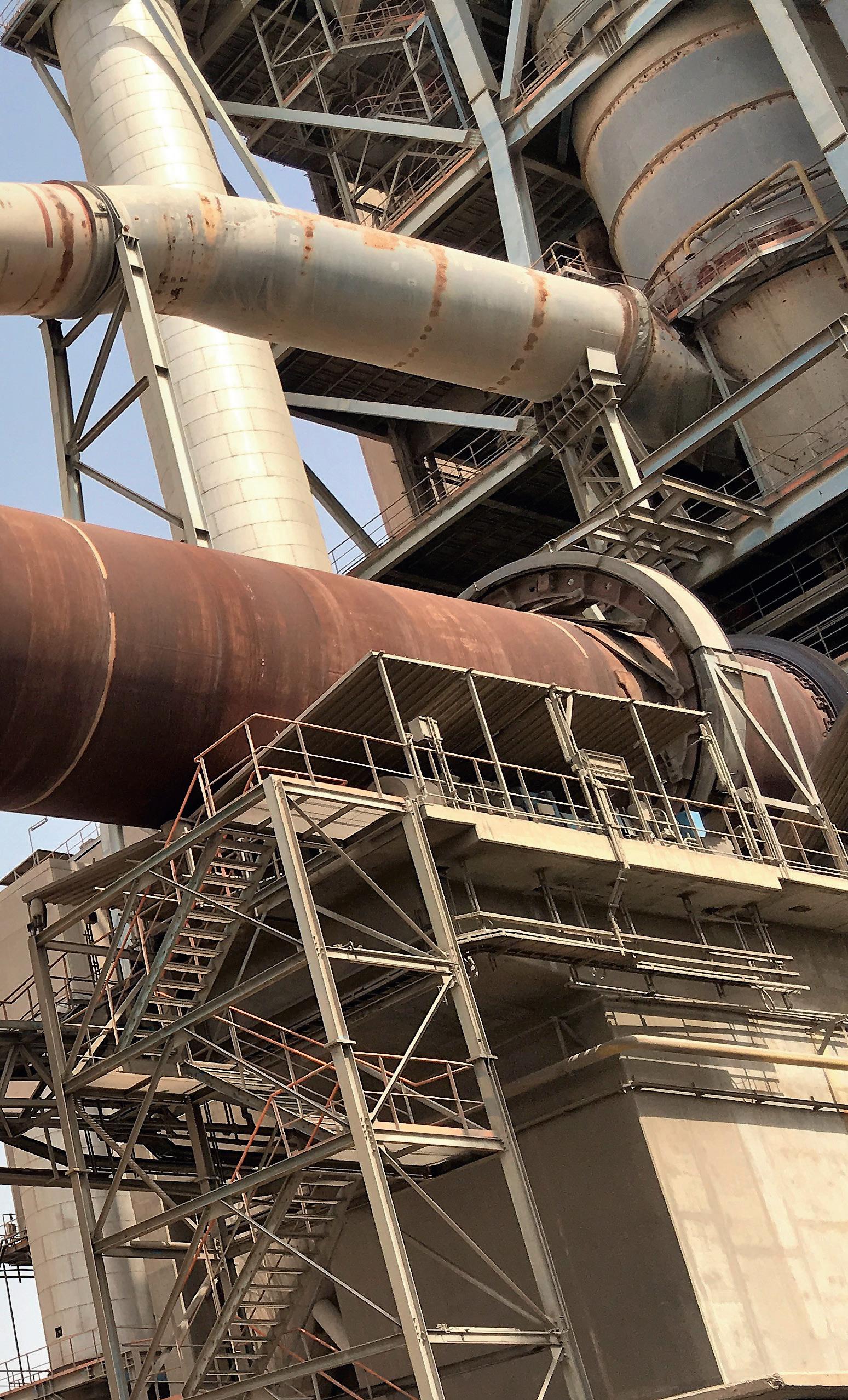
Emergency inerting systems are preventive explosion protection technologies that prevent the ignition of fires and dust explosions and thus reduce the occurrence of hazardous incidents. These systems are (mostly) fixed standby systems used in order to avoid dust explosions and to suffocate and extinguish smouldering or glowing fires of combustible dust in silos, coal mills, bag houses, or similar aggregates by creating an inert atmosphere. In case of a CH 4, CO, O 2, or temperature alarm the inerting process is initiated automatically by an independent PLC. Constant and reliable CH 4, CO, O 2, and temperature measurements are absolutely necessary.
A continuous reduction of the oxygen concentration to the limiting oxygen concentration (LOC) and a further reduction to the maximum allowed oxygen concentration (MAOC), with the injection of inert gas and permanent control and monitoring of the oxygen levels, is mandatory. The effectiveness of emergency inerting has to be verified via monitoring of the oxygen levels in the system. The maximum allowed O 2 concentration (MAOC) is an operational parameter that is set approximately 2 – 3% below the LOC, it is a safety margin set below the LOC.
In the case of abnormal levels of carbon monoxide (CO), oxygen, or heat, the inerting process is initiated automatically through an integrated process-control system. The goal at all times is to reduce levels to the LOC so that explosions can no longer take place. The LOC is the highest oxygen concentration at which an explosion cannot occur regardless of the dust concentration. The LOC depends on the kind of fuel that is used and needs to be determined separately in consultation with an authorised body. With lignite (brown coal) for example the LOC amounts to approximately 12% by volume using N 2,and approximately 14% when using CO 2.
Emergency inerting is discontinuous and can be used to prevent fires and explosions by extinguishing smouldering nests and glowing fires which can become the primary causes of the ignition and propagation of open fires.
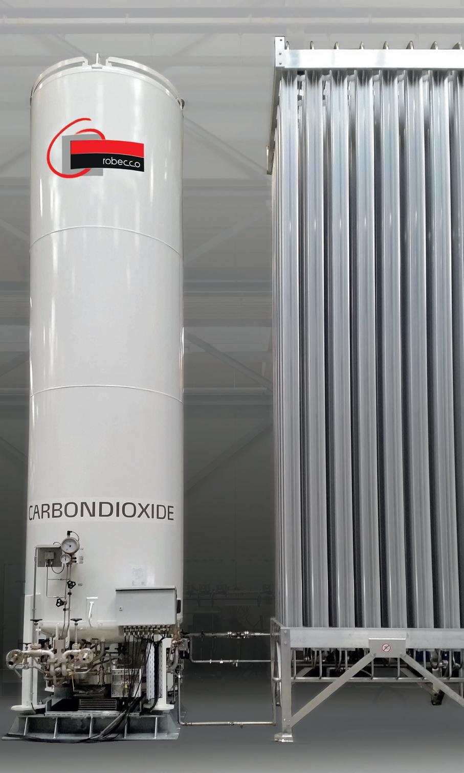
Depending on the inert gas used (source VDI2263-2) effectiveness for inerting generally decreases in the following order: f CO 2 f Steam f Flue gases f N 2 f Noble gases
The flow-through inerting method or the displacement inerting/flushing method is mostly practical. The necessary inerting time and inert gas volumes of individual aggregates with constant geometrical volumes is theoretically calculated during the engineering and design phase and has to be checked and corrected as necessary after commissioning by practical tests based on the measured MAOC value. The necessary inerting time and inert gas volumes of individual aggregates with variable geometrical volumes (e.g. silos) is theoretically calculated during the engineering and design phase according to different filling levels and has to be checked and corrected after commissioning using practical tests based on the measured MAOC value.
Inert gases have low levels of reactivity and are used to reduce oxygen concentrations to below critical levels. Inert gases act as simple asphyxiants, they displace the normal air and cause suffocation due to a lack of oxygen. By doing this, they prevent the occurrence of critical operating conditions and consequently any resulting explosions or fires. Different inert gases offer vary degrees of efficacy, and it is often not absolutely necessary to remove all of the O 2 .
Nevertheless, extinguishing smouldering or glowing fires of combustible dusts and powders is only possible at oxygen concentrations of 2 – 3% (maximum). Therefore, the inert gas concentration and related oxygen level has to be kept up over a longer period (several hours or days) until the fire is suffocated or extinguished. Monitoring and control of the effectiveness of emergency inerting is only possible with a combination of CO/CH 4 and O 2 measurements. A single CO measurement does not indicate any effectiveness, since the inert gas is diluting the CO level without giving any reliable information about the remaining oxygen concentration.
By installing the correct monitoring equipment and software, the tell-tale signs of a fire and subsequently an explosion can be detected in sufficient time to initiate the emergency inerting system and prevent both the fire and the explosion from occurring.
Generally, it is recommended to erect emergency inerting systems outside of a dust explosion area zone (20, 21, 22) according to European ATEX guidelines 99/92/EC (user guideline) and 2014/34/EC (product guideline). In a case where the emergency inerting system must be erected within one of these dust explosion zones, an ATEX guideline must to be applied for. Emergency inerting systems should be designed according to the following European directives: f European Pressure Equipment Directive PED 2014/68/EC. f European Machine guideline 2006/42/EC. f Low voltage guideline 2014/35/EC. f CEN/TR 15281:2022 Potentially explosive atmospheres. Explosion prevention and protection. Guidance on inerting for the prevention of explosions.
ATEX general requirements: principles of integrated explosion safety
Equipment and protective systems intended for use in potentially explosive atmospheres must be designed from the point of view of integrated explosion safety. 1
AND TEMPERATURE MEASUREMENT


