f Will Handle the Coming Gasoline Regulation Headwinds?


emission
tests,
terminals,
pipeline
stations
sources. Our software and services will keep you operational and compliant:
BREEZE ESP+ cloud-based emissions software f Expertise on Continuous Emissions Monitoring Systems (CEMS) f Stack testing procedural guidance and suitability
Air permitting for emission control devices f LDAR program implementation and compliance reviews, including on-site OGI monitoring Contact us today for more information at +1 972.661. 8881 or trinityconsultants.com/software. How
You
Distribution
BREEZE ESP+™ Software Can Manage the Calculations of Complex, Multi-Source Emissions
supply is particularly vulnerable as our two remaining refineries are set up to produce largely petrol (gasoline) rather than aviation fuel and diesel.”
Australia has shut down five refineries with a combined capacity of 553 000 bpd over the past decade. Ampol’s 108 000 bpd plant in Lytton and Viva’s 129 000 bpd Geelong plant are being kept alive by state subsidies. “Australia is almost entirely reliant on imports of refined fuels and crude to meet consumption. In FY2021, 91% of all fuel consumed in Australia was imported,” said the Australia Institute. “Fuel security has decreased over the last decade.”
Supporting this conclusion, the Lowy Institute slammed Australia’s approach to energy security as “a debacle”. The Sydney-based think tank derided the Morrison government’s landmark move in 2020 to stockpile some of its strategic oil reserves in the US as a “piecemeal” move that has “done very little to improve the country’s physical energy security.” The long-standing fear that meeting the 90-day stockpile requirement could significantly boost fuel prices has been a major reason for Australia’s reluctance to invest in expanding its strategic reserves.
Shell building oil products terminal in the Philippines
Following the closure of its only refinery in the Philippines, the local subsidiary of Shell has been expanding its oil import, storage and distribution business. Pilipinas Shell Petroleum Corp. (PSPC) recently announced it has begun constructing its fourth oil products storage terminal, but did not reveal the cost. PSPC said the 421 000 bbl terminal in the country’s southern island of Mindanao is due to begin operating in 3Q24. It will boost the company’s total storage capacity by 16% to 3 million bbl or 474 million litres.
PSPC said the terminal will enhance energy security in the region, which often experiences fuel supply disruptions caused by storms, floods, and other natural disasters. “The Darong Import Facility will allow us to fulfil our commitment to support economic activities as the Philippines continues to recover from COVID-19. It strengthens our capacity to continue to deliver quality fuels to our customers,” said Serge Bernal, Pilipinas Shell Vice President for corporate relations.
The Santa Cruz Storage Corp. (SCSC) will design, construct, and operate the facility for Shell under an exclusive term contract with an option to extend. The terms were not disclosed.
Shell’s other storage terminals
PSPC currently owns and operates a 166 000 bbl import terminal in Batangas city and a 340 000 bbl facility in Subic Bay, both located on Luzon Island, the country’s main economic region. The company’s largest terminal, with a capacity of 566 000 bbl, is located in Cagayan de Oro City in northern Mindanao. In 2020, PSPC shut down its 110 000 bpd refinery in Batangas and converted it into an import terminal to store and distribute oil products for the domestic market. Citing “demand destruction” from the pandemic, the company decided to shut down what used to be the Philippines’ second largest oil refinery, which started up in 1962. It then converted the facility into an oil storage terminal.
IndianOil to expand crude oil storage capacity in Gujarat state
Indian Oil Corp. Ltd (IOC) will build nine crude oil tanks with a combined storage capacity of 540 million litres (3.4 million bbl) at Mundra Port in India’s northwestern state of Gujarat. The investment will add to the port’s existing 12 tanks and boost total storage capacity by 75% to 1.26 billion litres, said Mundra’s owner, Adani Ports and Special Economic Zone Ltd (APSEZ). APSEZ and IOC did not reveal the project’s cost or when construction will begin. The new tanks will mostly stockpile crude oil for processing at IOC’s refinery located 1250 km away at Panipat, north of New Delhi. The Mundra tanks are linked to the 15 million t refinery, now undergoing an expansion by pipeline.
The new tanks are expected to be operational before the completion of the refinery capacity’s expansion to 25 million t by September 2024. APSEZ said its Mundra facilities are already providing the logistical services to discharge crude from very large crude carriers (VLCCs) berthed some 4 km off the coast into its storage tanks at the port before delivery by pipeline to the refinery.
“Mundra Port is a major economic gateway that serves the northern hinterland of India. As IOC’s trusted long-term partner, APSEZ is well equipped to handle the additional 10 million t of crude oil (supply) at our existing single buoy mooring (SBM) at Mundra,” said Karan Adani, APSEZ’s CEO.
Over the past decade, India has been expanding its oil, chemical, and gas storage facilities as well as refining capacity to meet the country’s rising energy demand. Russia’s war on Ukraine has added urgency to India’s programme to expand its energy-infrastructure as well as strategic petroleum reserves.
Vopak joint venture
Dutch storage giant Royal Vopak has completed its joint venture (JV) with logistics provider Aegis Group to become a major independent fuel and chemicals terminal operator in India. In a joint statement, the partners announced that Aegis Vopak Terminals will become the largest provider of independent tank storage services for LPG and chemicals in India. “LPG is earmarked by the Indian government to provide cleaner and safer cooking fuels for households,” it said.
Since the announcement of the JV plan in July 2021, Aegis Vopak has added three terminals to expand its network to 11 terminals in five ports along the east and west coasts of India. The terminals have a combined capacity of 1.5 million t.

Raj Chandaria, Aegis Logistics Ltd’s Chairman, said the JV will accelerate his company’s growth and enable its diversification into the energy storage business including LNG. Eelco Hoekstra, Royal Vopak’s Chairman and CEO, has set a goal for its new investment “to deliver growth over the next 10 years in line with the new [JVs] and India’s ambition for LPG.” He praised Aegis Logistics as “a reputed local partner with a ready organisation and proven track record of conceiving and executing tank farm assets in strategic locations along the Indian coastline.”
Vopak’s focus on meeting India’s demand for LPG storage ties in with its growth strategy. The company said it will “expand its network of LNG and LPG terminals at strategic locations” to increase exposure to the global gas markets.
10Autumn 2022


12Autumn 2022
On 10 June 2022, the US Environmental Protection Agency (EPA) proposed revisions to emission standards for the gasoline distribution industry. 1 These standards affect storage tanks, loading racks, and equipment components in gasoline service at thousands of gasoline distribution terminals, bulk plants, and pipeline stations. 2 The proposed revisions include several important increases in stringency, such as lower numeric emission limits, additional monitoring, and shorter averaging periods.

Background
The EPA has regulated volatile organic compound (VOC) emissions from the gasoline distribution sector under its New Source Performance Standards (NSPS) regulatory programme since the 1983 promulgation of ‘Standards of Performance for Bulk Gasoline Terminals’, Subpart XX.3 The NSPS requires most new and modified gasoline truck loading racks to meet an emission standard of 35 milligrams of total organic compounds (TOC) per litre of gasoline loaded (mg/L TOC).4 The NSPS requires monthly monitoring of loading rack equipment for leaks, by audio, visual, and olfactory (AVO), or ‘sight/sound/smell’ means. 5 NSPS XX also Harold Laurence and Behdad Yazdani, Trinity Consultants, USA, explain the EPA’s proposed revisions to emission standards for the gasoline distribution industry, and the implications for the storage sector.
Autumn 202213
introduced vapour tightness requirements for gasoline tank trucks. 6
In 1994, the EPA promulgated an emission standard regulating hazardous air pollutant (HAP) emissions from major source gasoline terminals and pipeline breakout stations: ‘National Emission Standards for Gasoline Distribution Facilities (Bulk Gasoline Terminals and Pipeline Breakout Stations)’, Subpart R. 7 This subpart required gasoline truck and rail loading racks to meet 10 mg/L TOC. 8 It required gasoline storage vessels (storage tanks) to install an internal floating roof (IFR) meeting most requirements of the storage tank NSPS, 9 and to retrofit certain deck fittings on existing gasoline storage vessels with external floating roofs (EFRs). 10 Subpart R required monthly AVO leak inspections, but the scope included all gasoline-service equipment at the terminal or breakout station.
Subpart R only affected larger terminals and breakout stations, those that met the EPA’s HAP major source threshold. By 1999, the EPA had indicated its intent to regulate gasoline distribution facilities that did not rise to the HAP major source threshold. 11 In 2008, EPA promulgated ‘National Emission Standards for Hazardous Air Pollutants for Source Category: Gasoline Distribution Bulk Terminals, Bulk Plants, and Pipeline Facilities’, Subpart BBBBBB (Subpart 6B). 12 Subpart 6B contained different sets of requirements for four source categories: bulk gasoline terminals, bulk gasoline plants (a throughput of less than 20 000 gal./d, pipeline pump stations, and pipeline breakout stations. Table 1 presents some key requirements of Subpart 6B.
Table 1. Selected requirements of current Subpart 6B
Affected source typeEquipment type
Bulk gasoline terminals, Pipeline breakout stations, Pipeline pumping stations
Gasoline storage vessel, either > 151 m3 (39 900 gal.), or 75 to 151 m3 (19 800 to 39 900 gal.) and throughput > 480 gpd
Other gasoline storage vessels
Gasoline loading racks, throughput > 250 000 gpd
Summary of revisions
EPA is required to review NSPS, such as Subpart XX, and National Emission Standards for Hazardous Air Pollutants (NESHAP), such as Subparts R and 6B, at least every eight years. 13 If needed, the EPA must revise the subparts to reflect the best demonstrated system of emission reduction (for NSPS) or to take developments in control technology into account (for NESHAP, a ‘technology review’). Table 2 presents the EPA’s key proposed revisions of the three subparts. New or more stringent requirements for loading racks, storage tanks, and gasoline-service equipment are proposed. Finalised rule revisions, which may differ from the proposed revisions, are expected on or about June 2023. A three-year timeframe to reach compliance with Part 63 rules means that the Part 63, Subparts R and 6B changes would apply on or about 1 June 2026. Performance testing would occur within 180 days from that date. 14
Certain aspects of the revisions to 40 CFR Part 60, Subpart XX, and 40 CFR Part 63, Subpart 6B merit further discussion.
Subpart XXa applicability date
Bulk gasoline plant
Emission standardSubpart 6B reference
Floating roof. IFR or EFR design. See Subpart 6B for detailed requirements
Fixed roof tank. Maintain openings closed when not in use
Vapour collection system. Reduce emissions to ≤ 80 mg/L TOC. Cargo tanks must be vapour tight
Subpart 6B Table 1 Item 2
Table 1 Item 1
Table 2 Item 1
Other gasoline loading racks Submerged fillingTable 2 Item 2
Equipment in gasoline service Monthly AVO leak inspection §63.11086(c)
Gasoline storage vessel > 250 gal.
Submerged fill pipe §63.11086(a)
Subpart XXa proposes much more stringent requirements for emission control devices on gasoline loading racks than the current Subpart XX. When such NSPS rules are revised, existing facilities come into compliance with the new rule only after the first time they are modified, or reconstructed, after the rule proposal date. Under NSPS rules, most changes to a facility that cause emissions to increase are ‘modification,’ and most changes that are more than 50% of the cost of an equivalent new facility are ‘reconstruction.’ 15 Most importantly, since the EPA published the proposed Subpart XXa on 10 June 2022, a loading rack project that takes place after this date may cause the loading rack to become subject to the final rule text of Subpart XXa, even though the rule is not yet final at present. Terminal operators should carefully consider the effects and schedules of capital projects affecting their loading racks, to assess if those projects will cause the racks to be subject to Subpart XXa’s stringent new standards.
Equipment in gasoline service Monthly AVO leak inspection §63.11086(c)
General Spill minimisation; open container covering §63.11086(d)
Instrument monitoring
Each of the proposed revised rules includes an
14Autumn 2022
instrument monitoring programme to detect leaks from equipment in gasoline service. None of the current rules for gasoline distribution facilities require instrument monitoring. Even bulk gasoline plants with throughput less than 20 000 gal./d would be required to conduct instrument monitoring.16
The proposed programme includes two options. One option is a Leak Detection and Repair (LDAR) programme using EPA Method 21 to detect leaks as is common at petroleum refineries or chemical plants. The other option is to use Optical Gas Imaging (OGI) to detect leaks. OGI technology creates images of hydrocarbon gases, such as gasoline vapours. The proposed rules only differ in frequency of monitoring, as shown in Table 2.
First-time implementation of an instrument monitoring LDAR programme requires advance consideration of several factors. Inspection logs required under current rules must be replaced with detailed, individually identified components. Typically, component
identifiers and monitoring results are stored in a dedicated LDAR compliance tool. A decision must also be made between selecting a contractor or training a terminal’s staff to provide routine monitoring. This decision would consider availability of contractors and of monitoring equipment.
Loading rack emission control device changes
The EPA’s proposed emission standard revisions to Subpart 6B are substantial for loading racks and associated vapour control systems at gasoline distribution facilities. According to the EPA, there are presently more than 9250 facilities in the US that are subject to Subpart 6B provisions. 17
The current Subpart 6B specifies that bulk gasoline terminals loading racks with gasoline throughput of 250 000 gal./d or greater must reduce the emissions of TOC to less than or equal to 80 mg/L TOC. This emission
Table 2. Selected proposed requirements for Subpart XXa and Subparts R and 6B, for equipment at bulk gasoline terminals, pipeline pump stations, and pipeline breakout stations
Affected source type
Subpart a Current requirements (summary)
Vapour combustion units (VCUs) b XX, XXaXX: 35 mg/L TOC for truck racks new/modified after 17 December 1980 80 mg/L existing 6 hr avg
Proposed requirements (summary)
• 1 mg /L TOC for new racks 3 hr avg
• 10 mg /L for modified/reconstructed racks 3 hr avg
R 10 mg/L TOC 6 hr avg 10 mg/L TOC 3 hr avg
6B 80 mg/L TOC for racks > 250 000 gpd 6 hr avg 35 mg/L TOC for racks > 250 000 gpd 3 hr avg
Vapour recovery units (VRUs) c XX, XXaSame as VCUs
• 550 ppmv TOC as propane 3 hr avg at new racks
• 5500 ppmv for modified/reconstructed racks
R Same as VCUs 5500 ppmv TOC as propane 3 hr avg
6B Same as VCUs 19 200 ppmv TOC as propane 3 hr avg
Open flares on loading racks d XX/XXa, R, 6BGeneral flare standards: §60.18 (XX) or §63.11(b) (R, 6B)
Gasoline storage tanks subject to Subpart R or 6B standards e R, 6BIFR or EFR
• See subparts for rim seal and deck fitting requirements
XXa: no flares allowed for new racks
Racks modified or reconstructed in XXa, or subject to R or 6B, may meet refinery flare rules at § 63.670(b)
• EFR tanks’ deck fittings must fully meet Part 60, Subpart Kb
• IFR tanks must conduct LEL monitoring during annual inspections
• LEL threshold is 25%, 5-minute avg LEL data to be collected every 15 seconds for at least 20 minutes
Equipment in gasoline service f (also applies to bulk plants under 6B)
XX/XXa, R, 6BMonthly AVO leak inspection, with leaks repaired
Method 21 leak monitoring or Optical Gas Imaging 10 000 ppm leak definition for Method 21
• XXa: Quarterly
• R: Semiannual
• 6B: Annual
a. Subpart XX requirements are not revised in the present rulemaking. Existing loading racks would comply with Subpart XXa after they are modified or reconstructed, and Subpart XX until then.
b. Current: §§ 60.502(a)-(b), 63.422(b), Subpart 6B Table 2 Item 1. Proposed: §§ 60.502a(b)(1), (c)(1), 63.422(b)(2), Subpart 6B Table 3 Item 1, docket EPA-HQ-OAR-2020-0371.
c. Current: same as VCU. Proposed: §§ 60.502a(b)(2), (c)(2), Subpart 6B Table 3 Item 3, as proposed in docket EPA-HQ-OAR-2020-0371.
d. Distinct from VCUs. Current: §§ 60.503(e), 3.425(a)(2), 63.11092(a)(4). Proposed: §§ 60.502a(c)(3), Subpart 6B Table 3 Item 2, docket EPA-HQOAR-2020-0371.
e. Under Part 63, Subparts R and 6B, tanks < 75 m3 (19 800 gal.) are exempt. Under Subpart 6B only, tanks from 75 to 151 m3 (19 800 to 39 800 gal.) are also exempt, if the tank’s throughput is 480 gpd (annual average) or less. Current rules: §63.423(a)-(b); Subpart 6B Table 1 Item
2. Proposed: §§ 63.423(c), 63.425(j), Subpart 6B Table 1 Item 2. EPA-HQ-OAR-2020-0371.
f. Current: §§ 60.502(j), 63.424, 63.11086(c), 63.11089; Proposed: §§ 60.502a(j), 63.424(c), 63.11089, as proposed in docket EPA-HQ-OAR-2020-0371.
Autumn 202215
standard is the same regardless of the type of vapour control system used. The standard excludes methane and ethane from TOC measurement. 18
By contrast, the proposed Subpart 6B specifies that such bulk gasoline terminals will need to reduce emissions of TOC to the levels listed below, depending on the type of vapour control system used. And the revised standard does not explicitly exclude methane and ethane.
n Therma l oxidation system other than a flare (e.g., vapour combustion unit): reduce emissions of TOC to less than or equal to 35 mg/L TOC, to be operated as specified in the proposed 40 CFR 63.11092(e)(2).
n Fl are: achieve at least 98% reduction in emissions of TOC by weight, to be operated as specified in the proposed 40 CFR 60.502a(c)(3).
n Vapour recovery system: reduce emissions of TOC to less than or equal to 19 200 parts per million by volume (ppmv) as propane, determined on a 3 hr rolling average.
Alternative monitoring changes
Gasoline distribution facility operators may face several potential challenges when complying with the proposed Subpart 6B standards. One potential challenge is related to the removal of alternative monitoring provisions in the current Subpart 6B rule for a thermal oxidation system other than a flare, such as a vapour combustion unit (VCU). Presently, monitoring of the presence of a thermal oxidation system pilot flame is allowed as an alternative to measuring the firebox temperature to demonstrate compliance with the monitoring requirements of Subpart 6B. 19 Gasoline vapours combust readily; for instance, butane has a net heating value (NHV) of 2985 Btu/ft 3 20
The proposed rules disallow pilot flame monitoring as a compliance option. New loading racks subject to the proposed Subpart XXa would be required to monitor firebox temperature continuously. 21 Loading racks subject to Subpart XXa due to modification or reconstruction, as well as racks subject to Subpart 6B, would have an additional option to monitor the NHV of the gases fed to the VCU. Such VCUs would follow rules for open flares at petroleum refineries. 22
A temperature monitoring method could result in the need to combust additional auxiliary fuel during periods of low gasoline loading, to maintain the firebox temperature at or above the level determined during the performance test. Furthermore, some facilities use a VCU as a backup vapour control system to their primary vapour recovery system for when the primary vapour control system is down. If the backup VCU is required to combust additional auxiliary fuel to maintain the firebox temperature, operation of the backup vapour control system may become cost prohibitive.
Facility operators should begin to develop their compliance approaches for thermal oxidation systems such as VCUs. From the more limited options available in the proposed rules, facilities should select a vapour
control and compliance demonstration approach that achieves compliance in a cost-effective manner.
Averaging period changes
The proposed rules also reduce the duration of averaging periods for loading rack emission control devices, creating another potential compliance challenge. For thermal oxidation systems other than a flare, the EPA is proposing that combustion zone temperature be maintained at or above the level determined during the performance test on a 3 hr rolling average basis. Similarly, the EPA is proposing a 3 hr rolling average monitoring period for the ppmv emission standards for vapour recovery systems. The current averaging period for performance testing for either type of control device is six hours. The change from a 6 hr to a 3 hr rolling average would impact design and operation of control devices.
In thermal oxidation systems such as VCUs, firebox temperature is related to the volume of gasoline vapours combusted at a given time. At most facilities, loading activities do not occur at a uniform rate throughout the day but are, rather, characterised by periods of higher or lower gasoline demand. On a shorter, 3 hr average, facilities would record greater variability in the VCU temperature. Changes in temperature due to varying gasoline vapour generation rate would not necessarily correlate with control device efficacy. Even so, operators would have a compliance need to stay above the required temperature minimum, such as by adding assist gas, shortening periods of higher loading rates, or smoothing periods of peak and low demand. This compliance need could result in capital costs, truck waiting time, and/or delivery delays.
In vapour recovery systems, a limit expressed as ppmv on a 3 hr basis is more stringent than the same limit expressed on a 6 hr basis. Facilities’ existing vapour recovery systems may need to be redesigned to be able to accommodate the proposed emission limit of 19 200 ppmv as propane on a 3 hr rolling average basis.
Preparing for the changes
The EPA has proposed substantial changes to air emission standards for the gasoline distribution industry. The proposed revisions include instrument monitoring LDAR requirements, revised monitoring requirements for storage vessels, and stricter emission standards for loading racks. The proposed standards may require affected facilities to undertake capital projects, to implement new compliance demonstration programmes, or to conduct internal feasibility studies for compliance planning. Gasoline distribution facilities should begin developing compliance strategies for the revised rules, especially as NSPS rules apply to facilities modified after the proposed rule date.
Note
For a full list of references, please visit www.tanksterminals.com/product-news/01092022/ change-ahead--references/
16Autumn 2022
Safety in confined spaces has been a problem in the industry for many years and a number of fatalities and injuries have occurred.
Robotic alternatives are now available, so it is not necessary to put personnel at risk working in hazardous areas, at height, or in confined spaces. The legal, financial, and reputational risks of fatalities in confined spaces can cause serious problems for companies if they have not considered alternative methods that are safer, such as robots or remote methods of inspection, maintenance, and cleaning, etc.

Professor Andrew Woods of the BP Institute at Cambridge University recently carried out a study of fatalities in confined spaces, which revealed that many senior managers are unaware of the safety levels required by regulators – usually one in a million or ALARP (as low as reasonably practicable).1
His research has revealed that most companies are operating below the broadly accepted levels of safety with consequent concerns on reputation, costs, and legal challenges if senior managers knowingly allow work to be carried out when safer methods are available at reasonable cost.
In 2020, HM Treasury in the UK assessed that the cost of an incident resulting in a fatality might be in the order of £2 million (~US$2.75 million).2 The ALARP principle, and regulatory guidance, suggests that expenditure to mitigate the risk should be in ‘gross disproportion’ to the cost of an incident, may be up to 10 times the cost.
 Danny Constantinis, EM&I Group, Malta, outlines how remote based inspections can contribute to efficient tank inspection, maintenance, and cleaning.
Autumn 202217
Table 1. Risk-based inspection methodology
What and where to inspect?When to inspect? How to inspect?
Determine inspection scope: risk-based prioritisation of components and damage mechanisms of concern
Determine inspection interval
Determine appropriate inspection methods
As far as floating production assets are concerned, nearshore or jetty moored assets are much easier to inspect than offshore, where different rules apply. With the current rush to install floating storage regasification units (FSRUs) around European coasts, many will probably end up in offshore or deepwater moorings.
The Classification Societies will almost certainly apply similar rules to those applying to FPSOs, drillships, and semi-submersibles.
Also, as far as LNG and hydrogen is concerned, cryogenic storage presents additional challenges in the ‘warming up’ and ‘cooling down’ of assets to minimise out-of-service periods. Robotic methods of inspection can be carried out at temperatures much lower than manned entry methods so tanks can be back in service sooner.
FSRUs usually have very large tanks so manned methods of inspection are difficult when it comes to coping with high level inspections, which would normally require scaffolding on very delicate tank linings. Most of the ‘sloshing’ damage of the liquid LNG or hydrogen occurs at mid-high level in the tanks so this is important.


Remote methods use tripods and telescopic masts with cameras lowered through tank openings to achieve the same objective and are much safer and faster. Out of service periods can be very costly, so the sooner that tanks can be back in service, the better.
EM&I has led a number of joint industry projects (JIPs) including hull inspection techniques and strategy (HITS) on behalf of the Global FPSO Research Forum, together with ‘FloGas’ and ‘FloWind’ for floating gas and wind assets. This keeps the company in touch with all the main stakeholders in each market sector so that all of the innovations are ‘industry driven’ and what owners and operators want. This has worked well in the FPSO industry where the HITS JIP has been operating successfully for eight years.
The ODIN® diverless UWILD (Under Water Inspection in Lieu of Drydocking) was one of the first innovations to come out of the HITS JIP, quickly followed by the NoMan® remote camera and synchronous laser scanning technologies. These have already been successfully used on many offshore projects.
The ODIN technology allows examination of the hull, propellor, rudder, bilge keels, sea chest inlets, and mooring chains, etc., using integrity Class ROVs. It is also possible to examine critical valves in operation from within the hull while the asset is on hire, on station, and in use, thus eliminating any out of service periods.
The valves can be inspected using patented ODIN access ports installed adjacent to the valves, so that specialised cameras on manipulators can be inserted through the access ports to examine the valves in operation. If any anomalies are detected, remote methods of isolation can be used to allow repair or replacement of faulty valves.
A number of associated technologies have also been developed to check pressure systems and electrical items safely, quickly, and economically. The ANALYSE TM pressure system technology significantly reduces the
Figure 1. Typical FPSO tank.
Figure 2. Typical manned entry.
18Autumn 2022
number of ultrasonic thickness measurements (UTMs) that need to be taken on piping and pressure vessels to ensure safe operation.

Electrical items can be checked easily and simply using the patented ExPert TM technology, which can ‘see through’ the junction boxes using specialised scanners to detect any anomalies, instead of having to isolate the circuit so that the electrical items concerned can be dismantled for inspection and then reassembled. This can often result in damage to the electrical components during dismantling and reassembly, so a less intrusive method is desirable.
Other technologies for extending the life of offshore assets include the diverless HullGuard® anode technology, which allows for cylindrical anodes to be inserted through Class approved access ports in the hull and then connected to an impressed current cathodic protection (ICCP) system.
Remote tank cleaning
It has become increasingly clear that, whilst remote tank inspection techniques are now developing apace, present and future techniques employ line-of-sight, that is to say that they need a clear line of sight to the structure under survey. Therefore, the success of such remote inspection techniques (RITs) is heavily dependent upon the extent to which such lines-of-sight are achievable. Risk-based inspection (RBI) is now a Class-accepted methodology for
carrying out Class surveys on floating units. The methodology is described succinctly in Table 1. It is apparent that the scope, ergo the extent, of inspection is related to the method of inspection proposed.
To date, the predominant inspection strategy has been the continuous hull survey cycle permitted by the Class Societies’ rules, whereby the prescriptive Class inspection requirements are applied i.e., general visual inspection (GVI) of an entire tank, close visual inspection (CVI) of a defined portion of the tank, and UTM of the defined structure within the tank. Up until very recently, RITs were unable to demonstrably carry out UTM to an acceptable Class standard. They have also been limited in performing GVI and CVI by the level of cleanliness in the tank. Of note, however, is that this is not from a failing in their functionality (unless their line-of-sight requirement is considered to be their failing and not one attributable to lack of cleaning). Instead, this is due to a lack of appreciation during the evaluation phase of the RBI strategy development. Because of these issues, RITs have not demonstrated effectively their ability to satisfy the inspection requirements of the continuous hull survey strategy under which they are being deployed. As a result, the benefits of remote inspection, which include significant safety benefits, have yet to be fully appreciated by operators and Class alike; in effect, we have been trying to fit the square peg of modern RIT methods into the round hole of traditional prescriptive inspections.
Paratherm has been the premier heat transfer fluids provider in the industry for over 30 years. We offer a wide range of heat transfer fluids and services to fit your process. Through providing users an extensive fluid analysis program, we deliver results that matter for your system. Our expert and knowledgeable technical staff provides superior service alongside our team of talented specialists and sales engineers dedicated to deliver. It’s what we’re most proud of. Our commitment to your process is what makes us the right choice for you! Learn more at Paratherm.com WE’RE IN YOUR INDUSTRY
With the increased uptake of RBI for hull structure, there is an opportunity for remote inspection to be shown to be commercially beneficial and much safer.
Whilst the stages to develop a RBI strategy are now well understood by floating unit operators, there can often be a misunderstanding by operators at the outset regarding the objective of adopting a RBI strategy. Since Class compliance can be achieved using the aforementioned continuous hull survey cycle, where 20% of tanks are inspected annually so that all tanks are inspected over a five-year survey cycle, one must ask what the benefits are believed to be for operators who wish to adopt a RBI strategy when the sought-after result must surely be the same i.e., Class compliance.
Operators generally perceive the benefits of adopting a RBI strategy to be some, or all, of the following:
n Reduced operational interference.
n Reduced production interference.
n Greater intervals between inspections.
n Lower number of inspections based on comparable tanks.
n Reduced extent of inspections. n Quicker inspections.
Remote inspection can play a significant role in achieving these benefits, particularly. What operators sometimes fail to appreciate is that the inspection findings will incur the same responses from their Class Society as if the findings were to be obtained from a traditional inspection by man-entry.

These responses may entail immediate repair, further inspection e.g., non-destructive testing (NDT), or increased inspection e.g., annual inspection. Such responses are not failings of the RBI or RIT, these are simply the consequences of inspection.


It is easy to denounce a remote inspection technique, for example because the tank subsequently requires manned entry. However, assuming the correct RIT and scope has been used, manned entry might be required to carry out remedial work (nothing to do with the RIT), or to carry out additional or confirmatory inspections (which are likely to incur less time in the confined space than carrying out the full traditional scope). It may also be simply the case that it was not understood that manned entry might be an outcome.
Of course, the response may also be one of acceptance by Class, resulting in no further intervention and time, safety, and cost savings that are attributable to the RIT. The advantage of developing an RBI strategy is that some of these potential outcomes are identified during the evaluation phase, their risk can be quantified and, if necessary, mitigated during the asset’s design or conversion, or during the RBI implementation phase.
So, what is the objective of adopting a RBI strategy?
The answer is not Class compliance but survey compliance, where the potential outcomes from the survey have been risk assessed as part of the process and either mitigated or deemed acceptable. Therefore, it is clear that the adoption of any RIT actually needs to be driven by the inspection strategy.
Figure 5. A NoMan camera can pan, tilt, and zoom.
Figure 3. A NoMan camera on a carbon fibre pole for high level inspections
Figure 4. Typical FSRU tank.
20Autumn 2022
Statistics coming out of the US tank cleaning sector are concerning. Approximately 2.1 million workers enter permit confined spaces annually and on average two workers die every single week in accidents related to confined spaces. Sadly, around 60% of those confined-space fatalities are would-be rescuers, leading to industry initiatives calling for an end to confined space entry in the US by 2025.
New benchmarks for safe tank cleaning are being reached with 100% no man entry systems. Robotic tank cleaning services can include fixed roof, floating roof, heavy fuel oil, and coned floor tank cleaning. Fully submersible robots operate in the most inhospitable environments. With specialised access cranage, remote camera systems, and engineering expertise, any size or shape of oil, gas or chemical tank can be cleaned.

Robotic equipment is dexterous and versatile and can navigate and work in its environment using multiple sensors and washers, while the robot's operator remains in a state-of-the-art control room, protected from hazardous conditions.

Cleaning schedules are ultra-precise because of the highly standardised and self-contained tank telemetry process that allows clients to accurately estimate the amount of time needed for cleaning any given tank. Advantages for tank terminals include fixed costs, reduced paperwork and permits, and no requirement for capital outlay and standby rescue teams.
To date, Re-Gen Robotics has been responsible for eliminating over 11 000 hours of confined space entry cleaning in oil and gas tanks. More than 40 tanks consisting of white oil, black oil, and distillate tanks in gas plants have been cleaned for oil majors such as Shell, P66, Valero, ExxonMobil, and Vermilion among others.
The following case studies demonstrate the variety of tanks and materials that robotic equipment can clean, the challenges encountered, the solutions implemented, and the benefits conveyed.
Fintan Duffy, Re-Gen Robotics, Northern Ireland, considers how robotic cleaning of tanks can improve safety and reduce the need for workers to enter tanks.
21 Autumn 2022
Shell UK Oil Products Ltd, Shell Haven Terminal
Re-Gen Robotics was commissioned by Shell UK Oil Products Ltd to clean two 30 m floating roof, Jet A1 fuel storage tanks at the Shell Haven Terminal in the UK.
Challenge
Both tanks had a resin lining applied to the floor and 1 m up the tank walls.
Solution
Magnetic tracks were removed from service for lined tanks and plain rubber tracks were fitted to the robot to protect the resin flooring.
Facts
Around 12 – 14 t of sludge was removed from each tank, with 2 t of water utilised for each tank. The number of robotic hours onsite were 90 per tank, and the number of man hours eliminated onsite were 448 per tank. It is estimated that a manned cleaning would have taken eight days, whilst the robotic cleaning took just three. In addition, less paperwork and permits were necessary and there was no requirement to spade tanks or for a standby rescue team. Scaffolding, cranage and vacuum jetting was also provided.
Conclusion
Overall feedback from Shell was very positive. These were the first tanks to be completely cleaned and inspected by Shell, worldwide, without the need for human presence in the tanks. Following this initial project, Re-Gen Robotics has been commissioned to clean more tanks at the Shell Haven Terminal. Shell has committed to end manned tank cleaning across its operations by the end of 2022.
Vermilion Gas Terminal
Re-Gen Robotics was commissioned to clean two 15 m tanks at a gas terminal that refines and purifies gas from a gas field in the west coast of Ireland. The first tank scheduled to be cleaned contained methanol and the second tank contained condensate, a low-density mixture of hydrocarbon liquids present as gaseous components in raw natural gas.

Challenges
The tanks were resin lined and contained a large amount of internal furniture including aluminium legs, skim arms and floating pontoons. Entry manholes were raised slightly higher than standard tanks, and there was a great deal of piping situated on the ground around the tanks’ exteriors.
Initial inspection verified that the height of the tank was considerably lower than most tanks. Therefore, it would be necessary to restrict the height of the telescopic camera bracket.
Solutions
Plain rubber tracks were fitted to the robot to protect the resin flooring, and an offset suction head was deployed to clean around heating coils.

The low-profile tool can access under pipes and has the ability to remove waste from below floor level. It can operate offset on the left, right, and straight-ahead positions. This tool alone can decrease tank cleaning time by 10 – 12%.
It was noted that a portable raised platform would be required to allow the robot to pass freely over the exterior pipework, to meet the manhole entry ramp. The platform was supplied by the client and was also used for the second tank clean.
Arrangements were immediately put in place to fit rubber stoppers around the ATEX camera and restrict the height of the camera bracket with a length of chain.
Figure 1. A remotely controlled Zone Zero certified ATEX robot entering an oil tank.
Figure 2. Re-Gen Robotics provide a complete system to clean a tank without the need for any scaffolding, cranage, or vacuum/jetting.
22Autumn 2022
Facts
Re-Gen Robotics notes that 7 t of sludge was removed from each tank, with 1.5 t of water utilised for each tank. The number of robotic crew hours onsite were 45 per tank, and the number of man hours eliminated onsite were 280 per tank. It is estimated that a manned cleaning would have taken five days, whilst the robotic cleaning took one and a half days. Once again, less paperwork and permits were necessary, there was no requirement to spade tanks or for a standby rescue team, and no requirement for capital outlay.
Conclusion
The speed and efficiency of the tank cleans exceeded Vermilion’s expectations, by finishing ahead of schedule and by significantly reducing the amount of tank downtime. Re-Gen Robotics continues to clean tanks for Vermilion.
Phillips 66 Humber Refinery
Re-Gen Robotics carried out the first no man entry crude oil tank clean for Phillips 66 Ltd’s Humber Refinery. Approximately 20% of all UK petroleum products come from the Humber Refinery. Re-Gen Robotics was commissioned to clean a 50 m fixed roof, cone-up floor crude oil (black) tank.

Challenges
Exact tank furniture details and volume of sludge were unspecified. The volume of waste inside the tank was understood to be approximately 135 t and the product temperature was ambient. The tank also had numerous steam coils, which the robot was required to navigate around.

Solutions
The robot is fully submersible and has an auger system located at the front which breaks down heavy sludge, without the requirement to use water, thereby generating less waste. The sludge was then extracted by an ADR certified jet/vac tanker with a 4800 m3 per hour vacuum capacity. The robot uses an offset suction head to clean around the heating coils.
Facts
536 t of sludge was removed from each tank, with 92 t of water utilised. The number of robotic crew hours onsite were 1520, and the number of man hours eliminated onsite were 12 160. It is estimated that a manned cleaning would have taken 95 days, whilst the robotic clean took 43. Less paperwork and permits were necessary, there was no requirement to spade tanks or for a standby rescue team, and no requirement for capital outlay.
Conclusion
Phillips 66 noted that the no man entry tank clean system could be adapted to suit its individual needs and timeframes. Following the initial contract, Re-Gen Robotics was commissioned to clean a further three tanks at the site and has recently been included in the tender process for 14 tanks over the next three years.
Summary
Ignoring safety critical maintenance and asset performance optimisation can lead to enormous loss; damage to
Figure 4. A robot fits through standard 600 mm manway using an externally fixed hydraulic ramp.
infrastructure; loss of production time; public investigations; environmental damage; fines; and can have a very negative impact on a company's brand values and reputation.
People can make mistakes in high stress situations, even when they are well meaning, so instead of trying to predict why and when accidents could happen, terminal operators can eradicate the problem by taking people out of tanks altogether. Inherent safety can be achieved by avoiding hazards completely, rather than trying to control them, and this is where massive cost and time savings can be made.
Figure 3. Re-Gen Robotics kit stationed at Shell Haven Terminal.
Autumn 202223
Confined space entry is one of the most dangerous types of work that inspectors perform. According to the Bureau of Labor Statistics, from 2011 – 2018 a total of 1030 people died due to occupational injuries involving confined spaces.1 These numbers are only for the US – the global count is likely much higher. In addition to the dangers of work inside confined spaces, inspectors who carry out tank inspections often face the additional hazards of working on ropes or at height on scaffolding while within a confined space.
Despite these dangers, confined space entry has historically been a necessary risk that inspectors assume for conducting tank inspections. But in the last few years, drones made specifically for operating in confined spaces are helping to change this reality.
Generally called indoor drones, these drones are protected by a cage and come with collision-tolerant features that allow them to bump and collide while operating in confined, cluttered environments, and continue flying unharmed.2 Advances are being made in this field all the time.

Flyability has recently developed a patented technology that enables its indoor drone to right itself after being turned upside down by a collision.
How indoor drones make tank inspections safer
A reliable indoor drone allows inspectors to collect visual or other data inside a tank remotely. The drone serves as a proxy for the inspector, flying into the confined space,

Autumn 2022 24
collecting the data needed for the inspection, and then flying out, all while the inspector remains safely outside of the tank.
Here’s how a drone inspection inside a tank works:
n Beforehand inspectors make a plan, identifying the outputs they need for their reporting and the data they need to collect.
n On the day, inspectors plan a flight path that allows them to collect all of the visual data they need to meet the requirements of the inspection. Often, multiple flights may be required to get all of the data needed.

n During the flight, inspectors identify potential defects, such as a crack in a weld, and collect as much visual data as they need to satisfy the requirements of the inspection.
n After collecting the data (typically photos and videos), inspectors review it to identify any potential defects that need to be included in their reporting.
The video footage that the drone collects acts as a historic record of the conditions inside the tank, allowing all the stakeholders involved in the maintenance process to see the same data and monitor changes within the tank over time.
Tank inspection by drone three case studies
This article will provide three examples of ways that indoor drones have been used by inspectors to improve safety in their work for inspecting ballast tanks on a drilling rig, cargo tanks on an FPSO, and an oil storage tank.
Zacc Dukowitz, Flyability, USA, explains how drones are helping to improve safety for tank inspections.
25 Autumn 2022
Drilling rig ballast tank inspection
In Brazil, administrators at a shipyard in the city of Angra dos Reis were looking for a new way to inspect their drilling rigs.3 They had previously carried out inspections by sending inspectors into their columns and ballast tanks via rope access. This approach was dangerous and expensive, since it extended the downtime in which the rig could not be used to drill.
To improve safety and reduce downtimes, shipyard administrators decided to test using an indoor drone for a tank inspection, and hired drone inspection service provider DR1 Group. The tests were a success, and DR1 Group was able to demonstrate that a drone could be used to collect visual data inside the ballast tank, reducing the danger to the inspector from confined space entry.
Benefits:
n Safety: no confined space entry or work on ropes was required for the inspection.
n Savings: 60% cost reduction by using the indoor drone instead of a traditional approach.
n Reduced downtime: an 80% downtime reduction was achieved by using the indoor drone instead of a traditional approach, cutting the total time for the inspection from five days to just one.
FPSO cargo tank inspection
A typical cargo tank inspection on an FPSO takes about two weeks, and often requires the use of scaffolding or rope access to allow inspectors to work at height.
The lost oil production caused by the two-week downtime presents a significant loss of revenue for the oil company. An added cost for the inspection is scaffolding, which can be expensive and time consuming to put up and take down.
To improve the process, inspectors at Texo performed a test cargo tank inspection with an indoor drone.4 To create the safest, most organised approach for the inspection, Texo partnered with DNV. Working with DNV and the FPSO operator, a new step-by-step process was created for how to perform an FPSO cargo tank inspection by drone.

Atmosphere explosible (ATEX) considerations were an important part of the process, given the potentially explosive environment in which the inspection would take place. To address ATEX issues, inspectors worked with the FPSO owners to undertake extensive hazard identification and comprehensive risk assessments, ensuring that the drone operations could be safely undertaken. The following steps were taken:
n First, all isolations were managed as per the operator’s standard procedures in order to eliminate any sudden combustible medium entering the tank during the survey.
n Next, the tanks were thoroughly cleaned to ensure that no manned entry would be required.
n Finally, the tank underwent active venting.
All the operations were conducted with gas monitoring prior to every launch. All of this was conducted under a Cat 2 Hot Works permit, with the appropriate risk assessment taken according to the requirements of the permit.
Benefits:
n Safety: using an indoor drone allowed inspectors to collect visual data inside the cargo tank remotely, which meant that no one had to perform confined space entry, use rope access, or work at height on scaffolding to collect inspection data.

n Speed: using an indoor drone reduced the time needed for the inspection from 14 days to just 4 days.
 Figure 1. The Elios 3, an indoor drone made by Flyability.
Figure 2. An indoor drone flies into a ballast tank on a drilling rig to collect visual inspection data. Credit: DR1 Group.
Figure 3. An indoor drone inside a cargo tank on an FPSO. Credit: Texo.
Figure 1. The Elios 3, an indoor drone made by Flyability.
Figure 2. An indoor drone flies into a ballast tank on a drilling rig to collect visual inspection data. Credit: DR1 Group.
Figure 3. An indoor drone inside a cargo tank on an FPSO. Credit: Texo.
26Autumn 2022
n Reduced work hours and savings: using an indoor drone reduced the number of people needed for the inspection from four to two. This meant significant savings, both in terms of labour costs and in terms of space needed for housing on the FPSO.
Bulk crude oil storage tank inspection
In an effort to improve its maintenance processes, Pertamina hired Halo Robotics, a drone technology company based in Jakarta, Indonesia, to help with a massive maintenance project at one of its oil refineries in Balongan, Indonesia, a refinery with a capacity of 125 barrels per stream day.5

The specific asset at the Balongan refinery that needed to be overhauled was a huge bulk crude oil storage tank. The tank shares features that are identical to those found in API 650 tanks, which are used for bulk crude oil and gasoline storage throughout the world, hypothetically making the results of –and methods used for – the maintenance project applicable to any refinery that uses API 650 tanks.
Pertamina’s requirements for this maintenance project were:
n To update the tank’s original drawings from 1972 with as-built schematics and blueprints.
n To systematically inspect the interior of the tank to determine engineering, procurement, and construction (EPC) requirements.
n To mitigate risk for inspection personnel by reducing the need for rope access and manned entry into tanks throughout the refinery, using this tank as a test case.
Credit: Halo Robotics.
n To improve the overall efficiency of EPC maintenance processes, including evaluation, planning, and project execution.
The inspection was completed successfully with the indoor drone. It took five days to complete the inspection, with inspectors conducting approximately 20 flights in that time.
Benefits:
n Safety: using an indoor drone to collect visual data inside the oil storage tank removed the need for manned entry via rope access and scaffolding, significantly improving safety for the inspection.
 Figure 4. Inspectors from Halo Robotics preparing to fly a drone inside a crude oil storage tank.
n Return on investment (ROI): costly, time-consuming inconsistencies between asset owners and EPC contractors were reduced with data collected by the indoor drone. Savings were also realised from reduced downtimes and not needing to build costly scaffolding.
n Efficiency for the oil storage tank inspection was significantly improved using an indoor drone, with processes created that can enable systematic, repeatable inspections of ageing assets for long-term analysis in the future.
The future of tank inspections with drones
In some instances, inspectors using indoor drones for tank inspections must still enter the tank to ensure that the drone is
getting full coverage. This means that inspectors still face the hazards of confined space entry in some instances. But advances in drone technology are removing even this limited need for confined space entry.

By using LiDAR data and SLAM (simultaneous localisation and mapping) technology, new indoor drones can create a 3D map of the environment in which they are flying as they fly.6 These 3D live maps provide inspectors with enhanced situational awareness of the environment in which they are operating, and can help ensure that they are getting full coverage without the need for them to enter the environment at all.
As drone technology continues to develop, the safety benefits it provides for those working in oil and gas, and specifically in tank inspections, will only continue to grow.

References
1. 'Fact Sheet - Fatal occupational injuries involving confined spaces - July 2020', US Bureau of Labor Statistics, https://www.bls.gov/iif/ oshwc/cfoi/confined-spaces-2011-18.htm


2. 'The best indoor drones of 2022 (new guide)', https://www.flyability. com/indoor-drone
3. 'Elios 2 cuts downtime by 80% in drilling rig ballast tank inspection', https://www.flyability.com/casestudies/drilling-rig-ballast-tankinspection
4. 'Texo pioneers remote inspection method in FPSO cargo tanks with the Elios 2', https://www.flyability.com/casestudies/fpso-cargo-tankinspection
5. 'Oil storage tank inspection sees improved safety, cost, and efficiency with the Elios 2', https://www.flyability.com/casestudies/oil-stroagetank-drone-inspection
6. 'What is simultaneous localization and mapping (SLAM)?', https:// www.flyability.com/simultaneous-localization-and-mapping
Figure 5. A drone pilot looks at a 3D live map created by an indoor drone.
REMBE® Your Specialist for Pressure Relief Solutions © REMBE® | All rights reserved rembe.com

 ozens Klein, Global Systems, Joel Hurt Jr., Leica Geosystems,
of terminals. Hundreds of tanks. Thousands of fabricated valve assemblies, meter runs, filters, separators, and other complex structures. All precisely located and managed through one accurate digital database that shows every piece of pipe, valve, fitting and weld complete with the diameter, grade, ANSI Class, wall thickness, coating, and inspection circuit or pressure zone. Once considered a futuristic ideal, this level of intelligence is rapidly becoming standard for the oil and gas industry as companies seek to maximise efficiency, sustainability, and regulatory compliance. Advances in technology over the last several years have made it possible to achieve sophisticated 3D asset management quickly and easily. Specifically, 3D laser scanning technology makes it possible to capture every Eric
Information
USA, and
Dpart of Hexagon, USA, describe how to quickly and easily digitise oil and gas assets to maximise efficiency and facilitate regulatory inspection and reporting. Autumn 202229
detail accurately in minutes, and intelligent databases ensure that all of the information is readily available.
The continued innovation in technology transforms the industry’s ability to quickly achieve incredibly accurate digital models that can be used to efficiently operate and manage assets and keep them in compliance.
Fast and accurate reality capture
Laser scanning is a noncontact and nondestructive method of digitally capturing physical objects in 3D ‘reality capture’ using a beam of light, or laser. The laser scanner, typically mounted on a tripod, captures millions of measurement points on any surface. These combined points are known as a point cloud – a comprehensive, clear, and precise digital record of the real-world environment that can be used for design and engineering, analysis, and even maintenance. Unlike CAD models, in which everything is shown level, square and plumb, point clouds capture the actual working system of pipelines, tanks, and facilities in the way that they exist in the real world, with all of their irregularities. Data capture is safe and efficient, with no need to climb ladders or balance on scaffolding to obtain the required measurements.
Oil and gas facility operators appreciate the rich detail of the 3D models developed from laser scanning, as well as the rapid turnaround on deliverables. Measurable point clouds can be available instantly, while models and comprehensive digital databases can be created in a matter of days. A natural progression is to expand digital asset management across entire operations.

But digitally documenting thousands of small facilities, tanks, and fabrications to meet regulatory requirements

 Figure 1. 3D asset management based on comprehensive and accurate laser scan data addresses regulatory requirements and answers any other questions that might arise about as-is conditions in the facility.
Figure 2. A handheld imaging laser scanner makes reality capture of oil and gas assets much faster, enabling a quicker turnaround on deliverables.
Figure 3. Corrosion inspection locations on piping and fittings.
Figure 1. 3D asset management based on comprehensive and accurate laser scan data addresses regulatory requirements and answers any other questions that might arise about as-is conditions in the facility.
Figure 2. A handheld imaging laser scanner makes reality capture of oil and gas assets much faster, enabling a quicker turnaround on deliverables.
Figure 3. Corrosion inspection locations on piping and fittings.
30Autumn 2022
presents some challenges when compared to the reality capture of large facilities. While tripod-based laser scanners are effective and efficient, they require time to set up and move to different locations. They also need a relatively flat surface with enough space to accommodate both the tripod and scanner. Expanding the use of laser scanning reality capture requires new, more flexible approaches that meet uncompromising accuracy standards.
Recent advances in laser scanning technology provide a compelling solution. For example, a handheld imaging laser scanner with a small, lightweight design is now being used to create a 3D digital twin comprising of millions of accurate measurements as the operator walks through a space. Using a combination of LiDAR scanning, visual simultaneous location and mapping (SLAM) technology, and an inertial measurement unit (IMU), the technology can identify different surfaces and unique geometry and calculate its 3D position as it moves through a facility.
These capabilities provide significant increases in productivity and safety for digitally documenting tanks, terminals, and other assets. Entire facilities can be captured in 30 minutes or less, making it possible to quickly document assets in thousands of facilities over hundreds of miles. The data capture is done with a single scanner operator with no impact to facility operations.
Easy inspections, reporting, and compliance
This accurate, comprehensive as-built laser scan data becomes the foundation for a comprehensive asset management system with layers of intelligence that can be used to maintain, analyse, and report on asset type, location, status, and condition. Any corrosion, deformation or cracking can easily be seen in the scan data. Repeating scans of the same areas over time and comparing them to previous scans can show metal loss rates and predict potential future problems. Adding drone imagery can give location context for a geographic information system (GIS) approach.
With this information, routine inspections and reporting to meet API and STI standards becomes both faster and easier. It is possible to pull up a 3D view of the asset with the inspection locations clearly visible, ensuring that the inspection is made in the right place. Information can be updated instantly in the field through a tablet computer or mobile device to keep the database current and accurate. That information can be connected to scheduling, asset management, and work management capabilities so that notifications are automatically sent when the next inspection

is due. And informative, visual reports can be generated in minutes with just a few clicks.
This approach enables the creation of an intelligent model that not only addresses regulatory requirements but also answers other questions about assets – including those that have yet to be considered. Data is no longer housed in siloes but is now liberated to unleash the full potential of the digital twin.
The next level of operational excellence
The advances in reality capture and asset management technology create new opportunities for tank and terminal operators.
Some organisations are already using point clouds to create virtual facility walkthroughs for training and virtual field visits. Others are pushing the envelope of what 3D asset management could be – capturing multiple large facilities with full-size tank farms, pump stations, terminals, and piping; linking piping and instrumentation diagrams (P&IDs) to intelligent models; integrating the data into a geographic information system (GIS) and other systems; and continuously updating the digital twin with more field data collection. The insight gained through this approach enables the owner to easily manage multiple facilities remotely.
Further advances in technology promise even more capabilities in the near future. Autonomous flying laser scanners and robot-mounted systems that can navigate around obstacles to capture measurements from the air and on the ground offer the potential for increased safety and unique insights in challenging environments. The continued evolution of augmented and mixed reality platforms will make it easier to visualise hidden or buried assets and make more informed decisions.
In many ways, though, the future is already here. A comprehensive approach to asset management is completely accessible to every oil and gas operation at every level. There is no better way to achieve regulatory compliance and operational value than with digital 3D asset management based on fast and accurate reality capture.
Figure 4. Corrosion inspection locations on piping and fittings in a GIS format with high-resolution drone imagery underneath.
Autumn 202231

 Ted Huck, Matcor, USA, delves into four strategies that can be taken when a cathodic protection system is no longer working.
32Autumn 2022
This article follows on from a previous article that featured in the Summer 2022 issue of Tanks & Terminals, entitled ‘Understanding cathodic protection systems’, and is intended to answer the question: what can I do if the cathodic protection (CP) system is not working?1
There are four basic strategies that may be considered when it has been determined that your CP system is not working properly. They can be summarised as follows: restore, replace, extend, or do nothing. This article will discuss each of these options in detail.

Restore
The first and simplest solution is to restore the existing system back to proper working order. In many instances, a CP system that is not working properly can be fixed with some minor repairs or simple adjustments to the system’s
operating parameters. This fix could be something as simple as replacing fuses on the transformer rectifier power supply. Or the fix could require tracing signals on the buried cables to/from the junction box to the transformer rectifier, or from the junction box to the edge of the tank ring wall. Cable breaks can quickly render a fully operable CP system inoperable. This can often be attributed to third party damage. Generally, these solutions are relatively easy to troubleshoot and can be implemented quickly, have only a modest cost impact, and do not impact the terminal’s operation.
In some cases, the CP system is fine, however, the transformer rectifier is not properly sized. This is common when the actual sand resistivity varies significantly from the design basis resistivity, resulting in a transformer rectifier that is either undersized or grossly oversized and needs to be replaced.
A subset of the ‘restore’ strategy has to do with those tanks where the CP system is operating properly yet the tank is not meeting criteria in one or more locations. What do you do when the potential readings at one or more locations may not be meeting criteria, yet the system is outputting the appropriate current needed to cathodically protect the tank bottom, and in some case much more than deemed necessary?
This is a tricky situation, in that the issue could be localised insufficient polarisation, which means that the tank would be at risk of corrosion in those localised areas. But it could also simply be an issue with the measurement mechanism and there really is adequate cathodic protection. Fixed location reference electrodes can go wrong but that does not mean that the CP system is not working properly. Pull tube reference electrodes can be susceptible to poor contact between the reference electrode and the exterior sand through the slots leading to dead spots in the pull tube where poor data may result. When two reference pull tubes are placed perpendicular to each other, one design to prevent the top pull tube being crushed against the bottom pull tube during compaction, is a four-way cross fitting. With these cross fittings there would be an extended area in the centre without slots leading to built-in dead spots. So, if there are a few bad readings but most of the readings are fine and the CP
Autumn 202233
system is delivering current as designed, perhaps there is no need to do anything other than to monitor the system and wait for your next inspection to confirm that there is no significant corrosion in those isolated areas where the readings are not satisfactory.
In this case, it is not a matter of restoring the CP system to proper performance, but rather accepting – based on the appropriate amount of current being supplied to the tank bottom and the preponderance of the readings – that the system is performing properly and thus excusing away one or more readings as being measurement issues.
Replace
When it has been determined that the restore (or accept as is) strategy is not an option, then the next consideration is the replace option. This is most common when the system is an older system that has reached the end of its useful life or
for a system where somewhere under the tank, the anode lead cables or system power feeds have been damaged or have failed. For older systems that are nearing or have reached the end of their life, the existing CP system may still be providing some current but less than what it was designed for and not sufficient current to meet polarisation criteria. For systems that have been damaged and/or have failed prematurely, the CP system most likely would not be able to discharge any current in some or all of the anode locations such that the system’s integrity is compromised beyond being able to restore by adjusting the system output or making simple repairs.
The replacement options are heavily impacted by whether there is an electrically non-conductive secondary containment liner below the tank bottom. The purpose of the secondary containment liner is to contain hydrocarbon products under the tank bottom in the event of a leak. Many tanks, especially older tanks, may not have any secondary containment liners directly below the tank bottom. Newer tanks may have geo-textile clay liners (GCL) – these liners contain hydrocarbons but allow for the flow of CP current (i.e., conductive liners). There are, however, many tanks that have been installed with some form of plastic sheet liner material such as high-density polyethylene. The plastic based liners are not conductive and so do not allow the flow of CP current.

If a tank has a non-conductive plastic sheet liner, the options to replace the tank CP system without replacing the entire tank bottom are quite limited. Any CP system replacement would have to be performed between the tank bottom and the liner. It is possible to lift the tank using air bags and cribbing to gain access underneath. This does require taking the tank out of service and can be both logistically challenging and quite expensive. Once the tank has been lifted, the CP system can be replaced (or in some cases repaired as needed.) Another alternative is to core drill through the ring wall and hydro jet new anodes in radially around the ring wall. This may slightly affect the integrity of the secondary containment system and is limited to tanks of about 50 m dia.
For tanks that do not have an electrically non-conductive liner that would shield CP current from reaching the tank bottom, there are several options available for installing a new CP system. The most common retrofit solutions include:

n Horizontal drilling of linear anodes under the tank.
n Shallow or semi-deep anodes located around the tank perimeter.
n Deep anode systems.
Each of these configurations has its advantages and disadvantages, and physical access limitations may preclude one or more of these types from being installed. When considering these configurations, current distribution, stray current interference, and testing provisions are all issues that need to be evaluated during the CP replacement system design.
Extend
The third strategy, should ‘restore’ or ‘replace’ not be an option, might be to extend the life of the tank bottom
Figure 1. Concentric ring linear anode being installed on top of liner in a tank bottom replacement project.
Figure 2. HDD drills boring under an existing tank to install new anodes.
34Autumn 2022
using volatile corrosion inhibitors (VCI). VCI technology has been around for a long time and has been used in a wide range of applications including tanks. The mechanism for corrosion control using VCI is to supply a sufficient chemical, in either a solid or slurry form, to deliver and release the chemical that diffuses inside the interstitial space and forms a molecular level inhibitor layer over the entire tank bottom.
The molecules are absorbed on the tank surface and suppress corrosion. A study by the Pipeline Research Council International (PRCI) found that VCI significantly reduced the pitting rates but not to a sufficient extent to meet AMPP (formerly NACE) requirements for effective CP.2 PRCI concluded that VCI provided some protection and would thus be suitable for service life extension for tanks where the CP systems have either failed or were not sufficient to meet criteria. The use of VCI in tanks continues to be an evolving technology, but they do offer a means to extend tank service life without having to take the tank out of service.
Do nothing
The final strategy if a CP system is not working is to simply do nothing. For this strategy, the owner should consider increasing the tank inspection frequency. Multiple floor scan results, taken over a given period of time, can provide an indication as to the condition of the tank and the tank bottom’s corrosion rate so that a future tank bottom replacement can be planned. When the tank floor is
reaching the end of its life and needs replacement, a new CP system can be installed at that time.
Conclusion
Corrosion is a significant threat to the integrity of an aboveground storage tank bottom, and good engineering practice includes providing cathodic protection. When that CP system is not working properly, the tank owner needs to evaluate which strategy fits best for that tank – restore, replace, extend, or do nothing.


References

1. HUCK, T., 'Understanding cathodic protection systems', Tanks & Terminals, (Summer 2022), pp. 49 - 52.
2. SHUKLA, P., et al., 'Vapor Corrosion Inhibitors Effectiveness for Tank Bottom Plate Corrosion Control,' PRCI Inc., Report Catalog Number PR–015–153602-R01, (2018).
Figure 3. Hydrojet anode installation using a core drilled hole through the ring wall.
Design Your Tank Ring Anode System in Minutes. matcor.com/TankApp ALWAYS SETTLE FOR BETTER Manufactured in the USA FACTORY SAFE TANK RING ANODE SYSTEM for reliable, long life tank cathodic protection
A


www.globalhydrogenreview.com
new magazine focused on the global hydrogen sector The Autumn issue of Global Hydrogen Review is out now Subscribe for free:
Choosing the right tank lining might not be the first consideration for many processing and storage sites. But with market conditions continually changing in the industry, it is essential that businesses keep ahead of the latest trends and adapt to suit them.

As part of this, the tanks at a facility must be flexible enough to cope with holding a wide range of products to allow the facility to maximise its profitability. The only thing that remains constant is the need to maintain the quality of the stored products/chemicals. Selecting the correct tank lining can support all of this, as well as save time and money. This article will outline seven of the most important points that should be considered when selecting a tank lining.

Hakan Altinoz, Jotun Performance Coatings, Norway, talks through a number of important points to consider when selecting tank linings.
Autumn 202237
Know the tank’s properties and prepare accordingly
What is the tank made of? Is it carbon steel? If so, it will likely need a lining to protect both the tank and the contents. If it is stainless steel, a lining may not be necessary.
Once the decision has been made that the tank requires a lining, preparation is critical to ensure that it is applied properly. Quality application means the tank lining remains in good condition for as long as possible, increasing periods between maintenance.
Blasting and cleaning will likely be required and humidity control is essential for a quality finish. Dehumidification (DH) equipment is often a good idea because it creates a suitable atmosphere for blasting, vacuuming, and coating. Where DH equipment is not used, it is important to control humidity and ensure good ventilation through other means.
What will be stored in the tank?
Will the tank store acidic products? Or amine-based liquids? Either of these can affect the tank lining, as can non-acidic materials like crude oil and hydrocarbon-based fuels. It is important to choose a lining that will protect the contents as well as the tank. If not, there is a high risk of contamination of the stored product.
Jotun has extensive chemical resistance lists for its tank linings, identifying a wide range of stored chemicals, along with storage temperatures and concentrations.
What temperatures will the tank have to handle?
Different products need to be stored at different temperatures. Crude oil, for instance, normally needs to be stored at temperatures of 60˚C or higher to ensure that the stored product remains liquid and can be pumped out of the tank. When storing this product in a lined tank, it is essential that the lining used can withstand the stored product at the required temperature.
Jotun’s Tankguard Plus, a novolac epoxy tank coating, has good resistance to high-temperature products including most sour crude oils and a wide range of chemicals and solvents.
Future-proofing a tank
A range of products and chemicals will likely be stored in a tank over its lifetime. To help with maintenance and ensure it remains operational, it is important to consider lining the tank with a coating that can deal with different products – now and in the years ahead.
A lining that can cope with the most extreme use is beneficial for a tank. While the initial investment might be a little higher, long-term savings can be achieved as it is not necessary to re-coat a tank should the product that it stores change. Making an evaluation as to likely production changes in the future will help to obtain the best protection for the tank and get it up and running again as quickly as possible.
How often will the tank be inspected?
For regular inspections, a lining with a good finish, that is easy to clean and able to withstand tasks such as degassing for tanks holding crude oil is recommended. Where regular inspections
How changing markets affect the chemical processing facility business
It remains difficult to predict with certainty the demand for future storage needs, but it is possible to future-proof tanks by ensuring they can handle a range of products and chemicals that can deliver significant benefits down the line.
Future-proofing the inside of tanks with a coating that has a wide chemical resistance is a relatively low-cost investment when compared to other aspects of tank lining such as scaffolding, blasting, ventilation or dehumidification. It can make commercial sense to upgrade the capabilities of the coating at relatively little cost to ensure peace of mind and confidence in the asset’s ability to meet future performance challenges from unspecified materials.
Different processes and products require varying temperatures. A chemical will typically be stored at a given temperature, so the tank must be able to handle the storage of a variety of chemicals at the temperatures required.
Adequate tank protection will help to ensure that product quality is maintained in the most efficient and profitable manner, and can avoid fears of lining suitability. A versatile product is an effective solution for delivering performance across a range of storage temperatures.
Knowing which tank lining to choose can be difficult. It is important to talk to a coatings manufacturer about which tank linings are best for which chemicals at which temperatures and concentrations. Coatings manufacturer's should also be able to answer a range of questions on back-to-service time, application complexity, and performance to ensure the system suits the specific requirements of the facility.
are not required, the lining must provide the right level of protection to ensure that it does not need to be regularly checked.
How quickly can the tank be returned to service?
This is a key consideration for maintenance managers. Time is money and a tank needs to be back up and running as quickly as possible during any shutdown, whether planned or unplanned. Even if a facility has spare tanks, this still means reduced flexibility and potentially operating at a lower capacity than necessary.
Products such as Tankguard SF, which allows wet-on-wet application, can help. Its film thickness versatility means that it can easily be applied in a two-coat wet-on-wet system, with a 20 – 30 minute gap before the next coat can be applied, which results in a safe, sound and solid solution.
Get the right support throughout a project
Choosing the right tank lining is an important and complex business. It is also important to choose a coating provider that can offer support before, during and after the job. When selecting a supplier, consider whether they also invest in rigorous product testing, have a vast amount of experience in tank linings, and a list of satisfied customers.
38Autumn 2022
THE INDUSTRY JUST GOT QUICKER


TankFast linings are formulated to allow your tanks to return back to service quicker than ever before, with excellent chemical resistance capabilities. It’s about time your tanks were earning to their full potential. It’s about time you opted for TankFast. Find out more at jotun.com/tankfast tanks back in


Take care of business from the inside.
Get your
service. Faster.


Place yourself at the heart of the leading bulk liquid storage event Get notified when registration is open www.stocexpo.com/register-your-interest 14 - 16 March 2023 Ahoy, Rotterdam Register your interest.
Aprevious article published in the Summer 2022 issue of Tanks & Terminals discussed how tank storage facilities can improve their gas detection coverage with new technologies. The article looked at how advances in wireless communication, battery technologies, and evolving industrial standards and technical reports (e.g. NFPA 72, ISA TR 84.00.07/08) are paving the way for a broader use of wireless gas detection in industrial facilities.

This article will discuss recommended practices that will help users implement wireless gas detection systems, including deployment considerations. The focus will be on open wireless protocols, specifically WirelessHART.

Wireless gas detection – a preventive approach
The main purpose of a fire and gas (F&G) system is to mitigate a hazardous incident (e.g. explosions). Traditionally, the F&G system is activated after the incident has occurred and serves
as an active protection layer to avoid an escalation towards an emergency response (Figure 1).
The advent of open wireless network-based gas detection is expanding the way that users think about the topic. Gas detection is increasingly being used at the pre-incident phase where ambient gas concentrations can be trended, and an alarm can be triggered for operator intervention at the process control layer. This expansion of use at the pre-incident phase can be attributed to two reasons. Firstly, wireless gas detection has enabled the flexible deployment of gas sensors throughout the facility. Detectors can now be easily deployed in previously hard-to-reach areas because of wiring and conduit constraints. Secondly, it is easy to scale gas detection coverage with wireless sensors. Monitoring density in the facility can be increased quickly by deploying detectors within the boundaries of the wireless network.
This means that wireless gas detection has enabled operators to reach a scale of coverage that has been cost prohibitive with wired solutions. The speed of detection of
Chris Frail and Julian Yeo, United Electric Controls, USA, outline recommended practices to help users implement wireless gas detection systems in industrial facilities.
Autumn 202241
any leak accumulation is improved with more sensors on the ground. This facilitates a preventive (vs reactive) approach to gas detection so that the incident does not escalate to a mitigation or emergency response phase.
There are various aspects to deploying a wireless gas detection system. This article will examine two main areas, namely gas sensor location and wireless network considerations.
Gas sensor location considerations
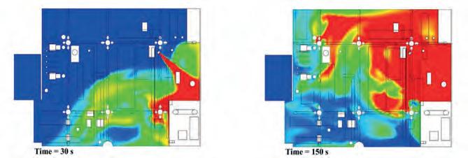
Personnel safety drives the intent of a gas detection system design. Gas detection layout should be executed in a way that achieves the objective of safeguarding personnel. For toxic gases such as hydrogen sulfide, emphasis should be on frequently trafficked routes and potential escape routes rather than on locating sensors all over the facility. For combustible gases, such as methane, emphasis should be on detecting accumulations of sufficient size quickly so that mitigation measures can be implemented immediately. To determine the optimal gas sensor location, there are several methodologies that can be employed, two of which are volumetric modelling and scenario-based modelling.
Volumetric modelling
This methodology is used for combustible gases and is based on the size of the target gas cloud. Target gas cloud
size refers to the critical volume of combustible gas that, if ignited, would result in an explosion. Several factors affect the degree of gas explosion, including the level of congestion and confinement of the area concerned.
Volumetric modelling of the target gas cloud is widely accepted for gas detection design. According to the UK HSE publication OTO 93-002, the threshold size for a pressure inducing explosion to occur is a 6 m cloud of stoichiometrically-mixed methane in a partially enclosed environment. With increased congestion or confinement, it would take a smaller critical volume of gas to be present for an explosion to occur.
As a result, one of the guidelines suggests a 5 m spacing rule between detectors to detect gas clouds before they can accumulate to a critical volume.
Scenario-based modelling
Scenario-based modelling considers various conditions that may affect how a gas leak migrates. The final output is usually a gas map (Figure 2). Gas mapping is a probability analysis that predicts the location of gas hazards and the likelihood of their occurrence. Gas maps are based on computational fluid dynamics (CFD) models, which use rigorous numerical analysis and algorithms to predict the flow of both liquids and gases. These mathematical calculations optimise gas detector placement, factoring in the following:
n Position in relation to assets.
n Obstacle analysis.
n Environmental conditions such as wind speed and direction.
As a recommended practice, gas mapping should be performed at the front-end engineering design (FEED) stage of the project life, immediately after the conceptual design or feasibility study is completed. When using scenario-based modelling, the user must be mindful that there is no limit to the number of possible scenarios, resulting in a greater-than-necessary number of detectors implemented.
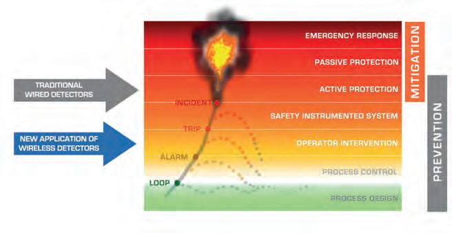
Sensor height
Determining the ideal sensor height is usually based on the personal knowledge and experience of operators. This can be an effective method, but offers no traceability. As a rule of thumb, to detect gases that are lighter than air, such as methane or ammonia, detectors should be mounted at a higher level where the gas is likely to migrate. For gases that are heavier than air, such as butane and sulfur dioxide, detectors should typically be mounted closer to the ground, but breathing zones should also be considered.
Figure 2. Model of gas leak (red) scenario-based modelling, 30 sec. and 150 sec. after leakage (image courtesy of MICROPACK (Engineering) Ltd, Aberdeen, Scotland).
Figure 1. Layers of protection.
42Autumn 2022


Need a reprint? +44 (0)1252 718999 reprints@tanksterminals.com We can tailor to your requirements, produce 1 - 12 page formats, print colour or mono and more
Table 1. Effective range of wireless connections in plant environments of various obstacle density* Degree of obstruction and effective range Description
Clear line of sight (225 m)Open areas with minimal change in the terrain level (less than 5˚ elevation). Device antenna mounted at least 1.8 m above obstruction height
Little obstruction (150 m)Lots of space between assets to facilitate propagation of radio signals, e.g. tank storage facilities
Moderate obstruction (75 m)A more congested environment but with adequate space to allow a vehicle (e.g. truck) to pass through between equipment and plant infrastructure
Heavy obstruction (30 m)A congested environment. Facility is too dense to allow for any vehicle to drive through it
*Used with permission from FieldComm Group, Austin, Texas, US
Hydrogen sulfide (H2S), for example, is a heavy gas with a breathing zone 1.2 – 1.5 m above ground.
Distance from leak
Detectors should be positioned away from high pressure leak sources, otherwise the gas expelled at high speeds may not be detected.
Detector orientation
Sensors should, for example, point downwards to prevent dust or water ingression. Where appropriate, the use of accessories such as a collecting cone can help to facilitate ambient sensing of the gases.
WirelessHART network considerations
To ensure optimal connectivity with the WirelessHART network, there are a number of recommended deployment practices/rules. The following are referenced from a 2016 technical guide for IEC 62591 WirelessHART installation.1 Also included are considerations for effective range and antenna selection.
Rule of three
For maximum redundancy, ensure that each field device has at least three neighbours within the effective range. That way, even if one or two of the primary paths becomes obstructed, there is still a redundant pathway back to the gateway via the third neighbour. These neighbouring devices can be instruments from any manufacturer, as long as they are WirelessHART compatible.
Rule of five minimum
It is recommended for a minimum of five devices in a WirelessHART network. Networks will work properly with fewer than five WirelessHART devices, but it becomes more robust with the addition of more. The WirelessHART network is self-organising and self-healing so new WirelessHART devices can be ‘dropped-into’ the network without affecting network design and reliability.
Rule of percentages
In scenarios in which the WirelessHART network has more than five devices, at least 25% of these devices should be in the effective range of the gateway to avoid pinch points and maintain reasonable bandwidth. For example, in a 100-device network, 25 devices should be within effective range of the gateway. WirelessHART networks can work with as few as 10% of the devices in the effective range of the gateway but results will not be optimal.
Effective range
It is recommended to organise WirelessHART devices by processing units within designated plant areas but within the effective range of an in-network device. When there is a clear line of sight, wireless signals can typically propagate around 225 m, but obstructions can significantly limit this range (Table 1).
Antenna selection
Effective range can also be affected by antenna selection so it is important to choose the right one. Here are some considerations for antenna selection:
n Clear the immediate area around the antenna.
Obstacles close to the antenna will provide much more interference than those far away, as they might reflect energy and change the radiation pattern of the antenna. The antenna will only perform as specified if there is approximately 0.5 m of free space around it. This includes the area behind the antenna range.
n Raise the antenna to improve its range. Raising the antenna above obstacles can often be more effective than increasing its gain.
n Choose the right antenna for the job. In general, a higher gain omnidirectional antenna is preferable in outdoor environments with fewer obstacles and little to no elevation gain. When indoors, a signal can be reflected off of several obstacles causing the line of site signal to be the weaker signal. In these environments, it is sometimes preferable to have a lower gain omnidirectional antenna that is less directive, especially if there is a significant elevation difference between sensors.
Conclusion
Gas detectors are only useful if they are deployed in the right location to detect leaks and protect lives. Wireless networks are only as good as their level of reliability. Balancing the gas sensor location and network considerations is key to a robust WirelessHART gas detection system. Where gas sensor location considerations conflict with network level considerations, the former should get priority. The emergence of open wireless standards in gas detectors has allowed brownfield facilities such as tank storage terminals to create an instant gas detection monitoring point, complying quickly with evolving safety and environmental regulations while reducing total expenditure.
Reference
1. System Engineering Guidelines IEC62591 WirelessHART, Emerson Process Management, (February 2016).
44Autumn 2022
Hydrocarbons are first stored at a terminal before being differentiated according to their applications and customers. They often do not have the same final recipients, with different markets, customers, and countries. For example, if an oil terminal supplies several countries, the taxes will differ whilst crossing different borders. Depending on the business activity (such as construction, agriculture, fishing, or mining), fuel taxes are often lower than those applied to private vehicles.
In order to differentiate hydrocarbons according to their final purpose, a colouring agent/marker is incorporated at the oil depot before the different shipments are sent or sold.

This colouring agent differentiates the hydrocarbons and allows traceability, both of which are simple anti-fraud solutions.


In Europe, marker injection is already carried out automatically with plates at the loading arms. Globally, there are still places where this mixture is done manually, often on the truck after the loading process, where the colouring agent is introduced in a defined quantity, by authorised personnel, before being sealed. Increasingly more injections are carried out at arm level, during loading, in order to rationalise equipment and storage. Marker injection can also be carried out in a regulatory environment and thus has to meet the requirements for legal metrology.
 Nicolas Winkler, ALMA, France, details the benefits of automatic marker injection at oil storage terminals.
Autumn 202245


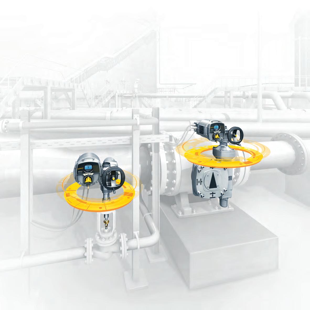


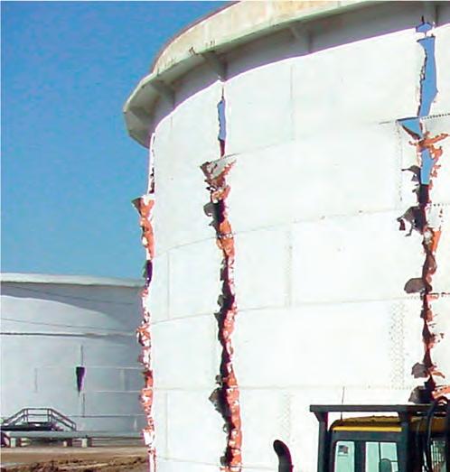
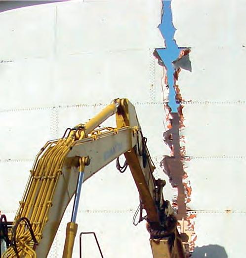


 Figure 2. Certification of global solution.
Figure 3. Injection marker storage tank on a compact and customised support in a depot/terminal.
Figure 2. Certification of global solution.
Figure 3. Injection marker storage tank on a compact and customised support in a depot/terminal.


