
8 minute read
Handling cathodic protection failure


Ted Huck, Matcor, USA, delves into four strategies that can be taken when a cathodic protection system is no longer working.
This article follows on from a previous article that featured in the Summer 2022 issue of Tanks & Terminals, entitled ‘Understanding cathodic protection systems’, and is intended to answer the question: what can I do if the cathodic protection (CP) system is not working?1
There are four basic strategies that may be considered when it has been determined that your CP system is not working properly. They can be summarised as follows: restore, replace, extend, or do nothing. This article will discuss each of these options in detail.
Restore
The first and simplest solution is to restore the existing system back to proper working order. In many instances, a CP system that is not working properly can be fixed with some minor repairs or simple adjustments to the system’s operating parameters. This fix could be something as simple as replacing fuses on the transformer rectifier power supply. Or the fix could require tracing signals on the buried cables to/from the junction box to the transformer rectifier, or from the junction box to the edge of the tank ring wall. Cable breaks can quickly render a fully operable CP system inoperable. This can often be attributed to third party damage. Generally, these solutions are relatively easy to troubleshoot and can be implemented quickly, have only a modest cost impact, and do not impact the terminal’s operation.
In some cases, the CP system is fine, however, the transformer rectifier is not properly sized. This is common when the actual sand resistivity varies significantly from the design basis resistivity, resulting in a transformer rectifier that is either undersized or grossly oversized and needs to be replaced.
A subset of the ‘restore’ strategy has to do with those tanks where the CP system is operating properly yet the tank is not meeting criteria in one or more locations. What do you do when the potential readings at one or more locations may not be meeting criteria, yet the system is outputting the appropriate current needed to cathodically protect the tank bottom, and in some case much more than deemed necessary?
This is a tricky situation, in that the issue could be localised insufficient polarisation, which means that the tank would be at risk of corrosion in those localised areas. But it could also simply be an issue with the measurement mechanism and there really is adequate cathodic protection. Fixed location reference electrodes can go wrong but that does not mean that the CP system is not working properly. Pull tube reference electrodes can be susceptible to poor contact between the reference electrode and the exterior sand through the slots leading to dead spots in the pull tube where poor data may result. When two reference pull tubes are placed perpendicular to each other, one design to prevent the top pull tube being crushed against the bottom pull tube during compaction, is a four-way cross fitting. With these cross fittings there would be an extended area in the centre without slots leading to built-in dead spots. So, if there are a few bad readings but most of the readings are fine and the CP

system is delivering current as designed, perhaps there is no need to do anything other than to monitor the system and wait for your next inspection to confirm that there is no significant corrosion in those isolated areas where the readings are not satisfactory.
In this case, it is not a matter of restoring the CP system to proper performance, but rather accepting – based on the appropriate amount of current being supplied to the tank bottom and the preponderance of the readings – that the system is performing properly and thus excusing away one or more readings as being measurement issues.
Replace
When it has been determined that the restore (or accept as is) strategy is not an option, then the next consideration is the replace option. This is most common when the system is an older system that has reached the end of its useful life or for a system where somewhere under the tank, the anode lead cables or system power feeds have been damaged or have failed. For older systems that are nearing or have reached the end of their life, the existing CP system may still be providing some current but less than what it was designed for and not sufficient current to meet polarisation criteria. For systems that have been damaged and/or have failed prematurely, the CP system most likely would not be able to discharge any current in some or all of the anode locations such that the system’s integrity is compromised beyond being able to restore by adjusting the system output or making simple repairs.
The replacement options are heavily impacted by whether there is an electrically non-conductive secondary containment liner below the tank bottom. The purpose of the secondary containment liner is to contain hydrocarbon products under the tank bottom in the event of a leak. Many tanks, especially older tanks, may not have any secondary containment liners directly below the tank bottom. Newer tanks may have geo-textile clay liners (GCL) – these liners contain hydrocarbons but allow for the flow of CP current (i.e., conductive liners). There are, however, many tanks that have been installed with some form of plastic sheet liner material such as high-density polyethylene. The plastic based liners are not conductive and so do not allow the flow of CP current.
If a tank has a non-conductive plastic sheet liner, the options to replace the tank CP system without replacing the entire tank bottom are quite limited. Any CP system replacement would have to be performed between the tank bottom and the liner. It is possible to lift the tank using air bags and cribbing to gain access underneath. This does require taking the tank out of service and can be both logistically challenging and quite expensive. Once the tank has been lifted, the CP system can be replaced (or in some cases repaired as needed.) Another alternative is to core drill through the ring wall and hydro jet new anodes in radially around the ring wall. This may slightly affect the integrity of the secondary containment system and is limited to tanks of about 50 m dia.
For tanks that do not have an electrically non-conductive liner that would shield CP current from reaching the tank bottom, there are several options available for installing a new CP system. The most common retrofit solutions include: n Horizontal drilling of linear anodes under the tank. n Shallow or semi-deep anodes located around the tank perimeter. n Deep anode systems.
Each of these configurations has its advantages and disadvantages, and physical access limitations may preclude one or more of these types from being installed. When considering these configurations, current distribution, stray current interference, and testing provisions are all issues that need to be evaluated during the CP replacement system design.
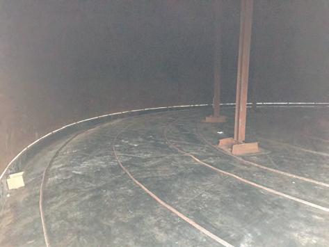
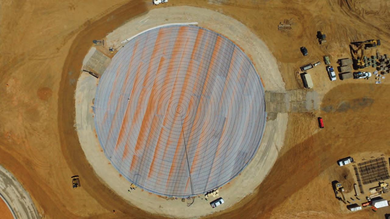
Figure 1. Concentric ring linear anode being installed on top of liner in a tank bottom replacement project.
Figure 2. HDD drills boring under an existing tank to install new anodes.

Extend
The third strategy, should ‘restore’ or ‘replace’ not be an option, might be to extend the life of the tank bottom
using volatile corrosion inhibitors (VCI). VCI technology has been around for a long time and has been used in a wide range of applications including tanks. The mechanism for corrosion control using VCI is to supply a sufficient chemical, in either a solid or slurry form, to deliver and release the chemical that diffuses inside the interstitial space and forms a molecular level inhibitor layer over the entire tank bottom.
The molecules are absorbed on the tank surface and suppress corrosion. A study by the Pipeline Research Council International (PRCI) found that VCI significantly reduced the pitting rates but not to a sufficient extent to meet AMPP (formerly NACE) requirements for effective CP.2 PRCI concluded that VCI provided some protection and would thus be suitable for service life extension for tanks where the CP systems have either failed or were not sufficient to meet criteria. The use of VCI in tanks continues to be an evolving technology, but they do offer a means to extend tank service life without having to take the tank out of service.
Do nothing
The final strategy if a CP system is not working is to simply do nothing. For this strategy, the owner should consider increasing the tank inspection frequency. Multiple floor scan results, taken over a given period of time, can provide an indication as to the condition of the tank and the tank bottom’s corrosion rate so that a future tank bottom replacement can be planned. When the tank floor is reaching the end of its life and needs replacement, a new CP system can be installed at that time.

Figure 3. Hydrojet anode installation using a core drilled hole through the ring wall.
Conclusion
Corrosion is a significant threat to the integrity of an aboveground storage tank bottom, and good engineering practice includes providing cathodic protection. When that CP system is not working properly, the tank owner needs to evaluate which strategy fits best for that tank – restore, replace, extend, or do nothing.
References
1. HUCK, T., 'Understanding cathodic protection systems',
Tanks & Terminals, (Summer 2022), pp. 49 - 52. 2. SHUKLA, P., et al., 'Vapor Corrosion Inhibitors Effectiveness for
Tank Bottom Plate Corrosion Control,' PRCI Inc., Report Catalog
Number PR–015–153602-R01, (2018).
FACTORY SAFE TANK RING ANODE SYSTEM
for reliable, long life tank cathodic protection
Design Your Tank Ring Anode System in Minutes.
matcor.com/TankApp
Manufactured in the USA
ALWAYS SETTLE FOR BETTER
A new magazine focused on the global hydrogen sector