Wild Well is the beacon of expertise in well intervention and remediation, where conventional methods falter. Our comprehensive services exceed the ordinary, enabling us to tackle projects on land and at any operational water depth with unparalleled precision and efficiency.
Our commitment to excellence is evident in our array of specialized services:
Hot Tapping: Safely determining the presence of pressure in oilfield equipment, when conventional methods fail, minimizing downtime, and maximizing efficiency.
Gate Valve Milling: Precision machining solutions to address valve obstruction and restore optimal flow up to 15,000psi.
Freeze Services: Create temporary pressure barriers in oil and gas wells by freezing existing fluids at ultra-low temperatures.
Cutting Services: Various cutting tools mechanical and abrasive can address different needs, from well bore tubulars to complete rig infrastructure.
Discover the power of unconventional intervention with Wild Well. Your challenges are our opportunities for transformation.
18 Making The Invisible Visible
Azka Yasyfa, James Fisher AIS, Indonesia, explores how the country is utilising digitalisation within its energy industries.
10 Playing The Right Role
Micah Smith, McKinsey & Company, USA, considers the role that the oil and gas industry has to play in the transition towards cleaner, less carbon-intensive energy sources.
14 Organic Oil Recovery With No Capital Expense
Dr. Colin K. Hill, Titan Oil Recovery, USA, explains how managing the biology and ecology of oil reservoirs can offer an effective method of reservoir optimisation with no capital expense.
22 Finding The Balance
Mojtaba Moradi and Mike Konopczynski, TAQA (Industrialization & Energy Services Company), UK, and Geir Frode Kvilaas, Aker BP, Norway, discuss how AOCDs can enhance well efficiency and reduce the costs associated with intervention and maintenance while providing data for future well completion projects.
28 From Ticking The Box To Becoming Top Notch
Dave Cormack, 3T Energy, UK, discusses the recent advancements in well control training.
32 Optimising Mud Loss Prevention
Qi Liu, CNPC Chuanqing Drilling Engineering, and Jack Wang, Vertechs Group, China, explore the advantages of integrating smart equipment and wellbore-strengthening technology while drilling in challenging vertical sections.
36 Bursting The Bubble
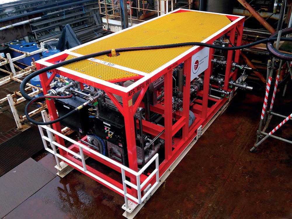
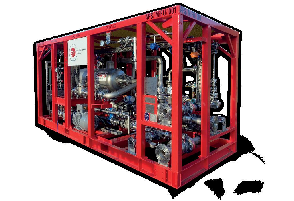
Frank Wurpel, Adaptive Process Solutions (APS), UK, outlines why many produced water treatment systems for ageing assets are no longer fit for purpose, and explores the different solutions available.
Front cover
The Organic Oil Recovery (OOR) process is an important reservoir optimisation and oil recovery breakthrough.
The performance record is good and the low cost of the process is a major benefit with no capital expense required.
Applied to production wells and through existing water-flood operations, Titan’s new oil recovery process works entirely within the natural ecology of the oil reservoir by selectively stimulating particular species of the formation’s resident microbes with custom-formulated, biodegradable and organic nutrients.
Our priority is the safe on-time delivery of your global energy projects. CRC Evans utilises market-leading welding and coating services, technologies and advanced data solutions, combined with a right first time approach.
Comment
Jack Roscoe, Editorial Assistant
jack.roscoe@palladianpublications.com
It has been a year since I started working for Oilfield Technology magazine, and I have recently found myself looking back on all that I have learnt and my experiences over the last 12 months. It was not difficult for me to pick a highlight, as in January 2024 I was lucky enough to attend Baker Hughes’ annual meeting in Florence. This was a fantastic occasion, where I jumped at the chance to learn about a variety of industries – listening to keynote speakers, exploring the Solutions Fair and interviewing Baker Hughes executives on mature assets, interventions and measurements.
During my lunch breaks and in the evenings, I took advantage of the lovely weather and seized the opportunity to explore the historic city. I strolled alongside the beautiful river Arno, gazed at the Duomo di Firenze and took in the magnificence of the Piazza della Signoria. However, it was difficult to ignore the fact that it all felt a little too pleasant.
Temperatures reached 17°C in January, 5°C higher than average, making it feel like the end of spring, rather than the middle of winter. This unseasonably warm month for Florence is just a small example of a much larger, and warmer, problem.
Italy has felt the effects of global temperature rises perhaps more so than any other country in Europe. In the summer of 2021, Floridia in Sicily recorded the highest temperature in European history with a high of 48.8°C, and just two years later the record was almost broken again with temperatures reaching 48°C on the islands of Sardinia and Sicily (again). There are no signs of things cooling down either; the National Oceanic and Atmospheric Administration says there is a 45.1% chance that 2024 will be the warmest year on record and a 99% chance that it will rank among the top five warmest years.1
It is not just Italy suffering; already in 2024 we have seen deadly and record-breaking heat waves in West Africa and South East Asia.2
The rise in global temperature and change to our climate is leading to more severe storms, increased droughts, a warming and rising ocean, loss of species, food shortages, increased health risks, poverty and displacement. It is the single most important issue of our time and collective urgent action is needed to tackle the crisis now. Therefore, the oil and gas industry is evolving and adapting to limit the effects of global climate change.
Florence has always been a city of change; it was the cradle of the renaissance in the early 15th century; the centre for artistic, architectural, cultural, economic and political developments. It felt appropriate then that in his opening keynote at the Baker Hughes annual meeting, Lorenzo Simonelli, Chairman and CEO of Baker Hughes, approached the room at the Opera di Frienze with a view to energise change.
He reminded the audience about the importance of improving the performance of mature assets. It was refreshing to hear this, and in the Solutions Fair, Baker Hughes displayed a set of innovative methodologies to accelerate production and total recovery while lowering CO2 per barrel.3
It is not just Baker Hughes that is working to solve this issue. For example, BP has installed methane measurement technologies and solutions across its North Sea oil and gas production facilities, and TotalEnergies has reduced emissions from oil and gas production by 34% since 2015, setting the company on track for zero methane emissions by 2030.4 – 5
The time for the oil and gas industry to act is now before it is too late, and this is being recognised across the sector. More companies are following the example of Baker Hughes, taking inspiration from the history of Florence, and energising change.
Deputy Editor: Emily Thomas emily.thomas@palladianpublications.com
Editorial Assistant: Jack Roscoe jack.roscoe@palladianpublications.com
Design
Production: Kate Wilkerson kate.wilkerson@palladianpublications.com
Production: Kyla Waller kyla.waller@palladianpublications.com
Sales
Sales Director: Rod Hardy rod.hardy@palladianpublications.com
Sales Manager: Chris Lethbridge chris.lethbridge@palladianpublications.com
Sales Executive: Daniel Farr daniel.farr@palladianpublications.com
Website
Digital Content Assistant: Kristian Ilasko kristian.ilasko@palladianpublications.com
Digital Administration: Nicole Harman-Smith nicole.harman-smith@palladianpublications.com
Events
Head of Events: Louise Cameron louise.cameron@palladianpublications.com
Digital Events Coordinator: Merili Jurivete merili.jurivete@palladianpublications.com
Marketing
Administration Manager: Laura White laura.white@palladianpublications.com
Reprints: reprints@palladianpublications.com
Palladian Publications Ltd, 15 South Street, Farnham, Surrey GU9 7QU, UK Tel: +44 (0) 1252 718 999 Website: www.oilfieldtechnology.com
World news
Aker Solutions secures long-term brownfield and modification frame agreement with Azule Energy
Aker Solutions has secured a sizeable long term frame agreement with Azule Energy to provide engineering, procurement, and construction services (EPC) for brownfield projects and modifications for two FPSOs in Angola.
This is a continuation of the current frame agreement Aker Solutions has with the operator Azule Energy. The operator is Angola’s largest independent equity producer of oil and gas and is an incorporated joint venture owned by Eni and BP.
The scope of work is focused on two FPSO (floating production, storage, and offloading) units, namely Greater Plutonio and PSVM. The work comprises engineering, procurement, and construction services (EPC) of the brownfield maintenance and modifications scopes.
The contract is a frame agreement covering maintenance and modifications activities with a duration of three years plus two one-year options. The contract will be executed and delivered by the Aker Solutions team based in Luanda, Angola, and Aberdeen, UK. The project management will be based in Angola to be close to the operation and continue to develop locally.
“We are building on our robust track record in Angola, dating back to 1998. Aker Solutions is a leading service operator and has a clear ambition to grow internationally. This new contract strengthens our global life cycle operations and is a pivotal project for our offices in Aberdeen and Luanda”, said Paal Eikeseth, Executive Vice President and head of Life Cycle, Aker Solutions.
Throughout the current contract period, there has been substantial growth in terms of in-country execution and the development of Aker Solutions’ local workforce. Currently, over 40% of the total scope volume is being executed in Angola, and a significantly increased target has been set for the new contract period.
“We are actively recruiting to enhance the strength and competence of our existing project team. Moving forward, our local business development efforts will focus on improving and strengthening relationships with local subcontractors, as well as hiring and training local personnel. We are pleased to have received renewed trust from Azule Energy and will continue to ensure the delivery of reliable and safe executions to safeguard the integrity of the FPSOs,” said Paal Eikeseth.
The Azule Energy-contract will be booked as part of Aker Solutions’ second quarter order intake in the Life Cycle segment.
Wood to deliver engineering contract with TotalEnergies in Iraq
Wood has been awarded a new US$46 million, three-year contract by TotalEnergies in Iraq.
Wood will provide front-end engineering design (FEED), detailed design, procurement support, and construction and commissioning assistance for the first phase of the Associated Gas Upstream Project, part of the Gas Growth Integrated Project (GGIP) in Southern Iraq.
The GGIP includes the recovery of gas currently flared in the Basra region to supply power generation plants, along with the construction of a seawater treatment unit and a 1GW solar power plant.
Shaun Dewar, Senior Vice President of Operations, Middle East and Africa at Wood said, “We are proud to support TotalEnergies on this project, which aligns with our shared commitment to pursue a secure and sustainable energy supply. We have a long-standing history of delivering engineering and consulting services in the region and this contract reaffirms our reputation for excellence.”
“This project will improve environmental sustainability through emissions reduction efforts. As part of this agreement, Wood will also continue to invest in local employment and skills development in the Basra region.”
The contract will be delivered by Wood’s teams in Basra and Dubai, creating 100 new positions. Wood currently employs over 1300 people in Iraq and the UAE.
May/June
2024
New Zealand
Triangle Energy Global has advised that preparatory works by the L7 Joint Venture with Strike Energy and New Zealand Oil and Gas to drill the Booth-1 well in the North Perth Basin are nearing completion and all regulatory approvals have been received.
Senegal
Woodside has achieved first oil from the Sangomar field offshore Senegal, marking the safe delivery of the country’s first offshore oil project.
Saudi Arabia
Wood has completed the front-end engineering and design (FEED) scope for the first phase of Aramco’s accelerated carbon capture and sequestration (ACCS) project in Saudi Arabia, expected to be the world’s largest carbon capture and sequestration (CCS) hub, upon completion.
North Sea
Weatherford International has announced that it has been awarded a two-year frame agreement extension with Equinor, for the delivery of completions, liner-hangers, and slot recovery services.
West Africa
Shelf Drilling has announced that it has secured a 15-month award for the Shelf Drilling Tenacious jack-up rig for drilling operations offshore West Africa.
World news
Diary dates
17 – 20 September 2024
Gastech 2024
Texas, USA www.gastechevent.com
28 – 30 October 2024
YNOW2024
Texas, USA www.yokogawa.com
04 – 07 November 2024
ADIPEC 2024
Abu Dhabi, United Arab Emirates www.adipec.com
19 – 23 May 2025
29th World Gas Conference (WGC2025) Beijing, China www.wgc2025.com
Web news highlights
Ì Eni divests 10% stake in Saipem for €393 million
Ì TotalEnergies sells its subsidiary in Brunei
Ì L&T wins offshore order from ONGC
Ì Sulzer supports TechnipFMC on innovative CO2 pumps for subsea oil and gas separation
Ì DNV and PETRONAS subsidiary partner on CCS value chains across Southeast Asia
To read more about these articles and for more event listings go to: www.oilfieldtechnology.com
May/June
2024
Odfjell Technology secures well services contract with HEYCO Energy Group
Odfjell Technology has been awarded a contract for onshore activity by energy portfolio company, HEYCO Energy Group. The agreement will support Odfjell Technology’s long-term growth plans to expand its well services operations across continental Europe.
The contract will focus on the Viura Field in Northern Spain, where 85% of the country’s natural gas is produced. Odfjell Technology will supply two key services from its well services suite – tubular running services (TRS) and drilling tool rental – with the possibility of extending to well bore clean up services. These services will be delivered on up to three wells. Odfjell Technology TRS crew will be used to deliver the casing running works.
“Securing this contract with HEYCO Energy Group marks a milestone for Odfjell Technology’s well service strategic growth as we look to expand our presence in Spain and more widely across continental Europe,” said Alex Gomoescu, VP Continental Europe Well Services at Odfjell Technology. “Both companies are built with strong heritage and extensive experience at the core, and we look forward to collaborating with HEYCO Energy Group to support its efforts with our innovative, class-leading well services offering.”
HEYCO Energy Group manages oil and gas exploration and development projects in the United States and Europe. The company has been strategically investing in oil and gas plays in the UK and Spain for more than 20 years.
“Odfjell Technology brings experience and operational excellence to our Viura Field development,” said Manuel Gervilla, Technical Director & DF – HEYCO Iberia. “We are proud to have them as part of our team.”
Subsea7 awarded contract for the Bittern field in the UK North Sea
Subsea7 S.A. has announced the award of a sizeable contract by Dana Petroleum (E&P) Ltd, for the Bittern field development, located approximately 190 km east of Aberdeen in the UK Central North Sea, at a water depth of 90 m.
The contract scope includes project management, engineering, procurement, construction and installation (EPCI) of a 22 km 12 in. water injection pipeline. Subsea7’s scope also includes associated subsea structures and tie-ins at the Triton floating production storage & offloading (FPSO) vessel and the Bittern field.
Project management and engineering work will commence immediately in Aberdeen. The offshore activities are scheduled for Q325.
Pytheas Energy acquires interest in three oil-producing properties
Pytheas Energy has announced the addition of three producing oil and gas properties to its growing portfolio, the Andrews Crane Asset, the Bakken Asset, and the Minerva-Rockdale Asset.
These represent both working and non-working interests in 620 oil and gas wells, with a combined gross current production of approximately 357 bpd.
CEO Josh Zuker said, “We’ve grown considerably over the past three months. Today, Pytheas Energy holds interests in over 600 oil wells, which we acquired at what we believe were below-market prices. This is thanks to our proprietary, AI-enabled asset identification technology.”
World news
FEED contract award for the Zama project offshore Mexico
The Zama Unit partners Wintershall Dea, Pemex (operator), Talos Energy and Harbour Energy have awarded the front-end engineering and design contract (FEED) for the development of the Zama oil field to the French engineering company DORIS.
“Zama is currently one of the most important energy projects in Mexico and we are very pleased to have reached the next milestone”, says Martin Jungbluth, Managing Director of Wintershall Dea in Mexico. “Our goal is to develop this large field safely, in the most efficient timeline and in the best possible technical way. With DORIS we have a very experienced partner for the FEED phase at our side.”
The FEED work will be based on the scope of the unit development plan approved by the Mexican Hydrocarbon Commission (CNH) last year. It covers the planning of two offshore platforms, 68 km of pipelines and cables as well as a new onshore facility, fully dedicated to the Zama project, located in the Dos Bocas Maritime Terminal, in Paraiso, Tabasco. The Zama Unit partnership also plans to minimise greenhouse gas intensity by using the best available technology, produced gas for onshore power generation, as well as best use of existing storage and transport infrastructure.
DORIS will collaborate with the two Mexican engineering companies NOMARNA and SUMMUM to carry out the FEED work.
“The award of the FEED is a great result thanks to the good cooperation in our integrated project team (IPT), in which colleagues from all four Zama partner companies work together on this extensive and important key project every day. I am pleased that we are making good progress, together, as one team”, underlines Sylvain Petiteau, Vice President Zama Project.
Zama is one of the world’s largest shallow water discoveries in the last 20 years and was the first discovery made by an international consortium in Mexico in 2017. With estimated gross resources of 600 – 800 million boe, Zama is expected to make a significant contribution to Mexico’s energy supply over the next 25 years, creating activity that will support the growth of the country’s energy sector and generate a large number of jobs in the coming years. The field is expected to produce up to 180 000 bpd at its peak, which corresponds to around 10% of Mexico’s current total oil production.
Once these studies have been finalised, the Zama Unit partnership will proceed with the tendering process of the engineering, procurement and construction (EPC) contracts, followed by the final investment decision.
Trendsetter wins major contract in Brazilian market with Trident Energy do Brasil
Trendsetter Engineering has announced that it has been awarded a significant contract by Trident Energy do Brasil to deliver two six-slot production subsea manifolds for the Bonito and Bicudo Fields in Brazil.
This contract encompasses the design and manufacture of the subsea manifolds, associated pipework, and mudmat foundations.
This contract award comes on the heels of Trendsetter’s strategic entry into the Brazilian market with the establishment of local facilities in Macaé, Brazil. In so doing, Trendsetter can now better support its customers locally while adding value through partnerships with Brazilian supply chain partners.
“We are excited to strengthen our successful relationship with Trident Energy do Brasil with this latest production manifold project,” said Hamed Moshrefi, Director of International Operations for Trendsetter. “We are committed to expanding our presence in Brazil and enhancing our value-added support for Trident Energy do Brasil.”
The contract includes production valves sourced from Advanced Technology Valve (ATV) in Colico, Italy. The equipment is scheduled for delivery in Q325, with offshore installation to follow.
Baker Hughes awarded major integrated solutions contract for Petrobras’ offshore fields
Baker Hughes has announced a significant order from Petrobras for workover and plug and abandonment (P&A) services in pre-salt and postsalt fields offshore Brazil.
The multi-year project, set to start in the first half of 2025, will be managed with Baker Hughes’ integrated solutions portfolio to optimise performance for Petrobras. Baker Hughes’ integrated approach will deploy wireline, coiled tubing, cementing, tubular running, wellbore intervention, fishing, and geosciences services in all of Petrobras’ offshore fields. The agreement also includes Baker Hughes remedial tools, completion fluids and production chemicals.
“Baker Hughes brings to this important project a comprehensive technology portfolio, a deep understanding of localisation, and a rich history of working in Brazil,” said Maria Claudia Borras, Executive Vice President, Oilfield Services & Equipment at Baker Hughes. “Flawlessly integrating these capabilities will be essential to the success of the project. Our expertise in integrated solutions is the foundation for efficiently taking energy forward in Brazil.”
The energy transition towards cleaner, less carbon-intensive sources is real. Oil and gas are not going away any time soon. That may sound like a contradiction, but it is more like a description.
While fossil fuels are projected to see potential declining demand in the coming decades, they will still be a significant part of the energy mix. This will be the case even in scenarios where the world substantially accelerates progress towards net zero.1
Climate policy is focused on reducing greenhouse gas (GHG) emissions to achieve the 1.5°C pathway which was set out in the 2015 Paris Agreement and reaffirmed in the COP 28 UAE Consensus in December 2023.2 However, it is just as important to ensure access to an affordable, reliable, and competitive global energy supply for everyone, everywhere. All four elements are related to each other and addressing all four is essential to a successful transition. Otherwise, the unsteady progress towards substantial emissions reductions could stall further; there are and will be trade-offs.
Recent history confirms this. Germany has been a committed climate change actor, but when it faced the risk of energy shortages due to the invasion of Ukraine in 2022, one of its responses was to re-open coal plants to ensure that its economy could function and that its people could stay warm.3
Given this context, there are two questions to answer: how can the oil and gas industry play a role in the energy transition and what exactly can it do?
How can the oil and gas industry play a role in the energy transition?
The oil and gas industry has a critical role to play in the energy transition. For a start, given economic and population growth, the demand for energy will continue to grow. In its most recent Global Energy Perspective, McKinsey estimates that demand for power will rise 3 – 4% a year to 2050.4 At the moment, 80% of global primary energy demand is supplied by fossil fuels (coal, gas, and oil) which is about the same as in 1997, the year of the first global climate conference.4 – 6
There is, however, a world of change in the works. McKinsey projects that oil demand could peak in the 2030s and then decline through 2050 (although the scenarios vary widely, with projected declines ranging from 3% to close to 50% depending on the speed of the transition). For gas, the peak will likely come later, potentially in the 2040s, but could plateau or even keep rising for years after that, though at a slower rate. At the same time, the analysis sees renewables and other low-emissions sources of energy continuing their strong growth; they could account for 65 – 85% of global power generation by 2050.7
It is important to remember that there is a human dimension to energy, in the form of economic development. Almost 775 million people lack electricity and 2.4 billion people still cook with traditional fuels – a practice that costs nearly 3.2 million premature deaths a year.8 –10 Mckinsey estimates that 4.7 billion people live under what is called ‘the empowerment line’, defined as having the means to securely meet basic needs, including nutrition, health, shelter, education, water, and energy.11
Micah Smith, McKinsey & Company, USA, considers the role that the oil and gas industry has to play in the transition towards cleaner, less carbon-intensive energy sources.
Playing The Right Role
Right now, oil and gas account for about 170 million bpd of accessible and relatively low-cost energy, which cannot easily be replaced. When the International Energy Agency (IEA) modelled future trends, assuming the world comes close to net zero in 2050, it projected that fossil fuels would still account for a quarter of energy demand in 2050. Oil and gas make up the great majority of that, as the use of coal continues to decline.12
What it comes down to is that the energy transition is rightly named – the world cannot just switch off fossil fuels. It must transition. And a muddled transition (one that does not bear affordability, reliability, and competitiveness in mind as well as sustainability) risks losing public support, making getting to net zero even more difficult than it is proving to be, and most critically could put lives and livelihoods at risk. Despite all the efforts of recent years, which have slowed the rate of GHG emissions growth to levels not seen since the depression, global emissions are still rising, hitting a record in 2023.13 The IEA noted that consumers have very low tolerance for unreliable or very expensive energy.14
The oil and gas industry has a dual role – to help ensure that the existing system can power peoples’ lives and livelihoods even as the new system is being built in parallel – and to do so with the lowest emissions possible.
What exactly can the oil and gas industry do?
The short answer is quite a lot. As a matter of common sense, cutting emissions requires going where the emissions are. McKinsey’s Managing Director, Bob Sternfels, believes that the bigger the player, the bigger possible reductions can be.15
The oil and gas industry is a big player – its operations account for about 10% of global emissions. By making steady progress on its own emissions (known as Scope 1 and 2), the industry can make a discernible difference. One initiative in this direction is the Oil & Gas Decarbonisation Charter. Launched at COP28, it was signed by 50 companies (including 29 state-owned ones) that account for over 40% of global production.
The Charter sets out two commitments. The first is to reduce methane emissions to near-zero by 2030. The energy sector accounts for 40% of man-made methane emissions and methane is a powerful GHG, responsible for about 30% of temperature rises since the industrial revolution.16 Containing fugitive emissions is eminently doable; indeed, a number of companies are doing it. With greater use of satellite-based and laser-based monitoring and blockchain technology, more can be done, and at diminishing costs. Already, many efforts are cost-effective, through the sale of the captured gas. There is a strong case for making methane reduction a universal practice, which would reduce oil and gas industry emissions by up to half. 17
The second commitment is to be net zero in operations by 2050. Opportunities include electrifying pumps, motors, and furnaces, enhancing energy efficiency, and cutting transport emissions through the use of artificial intelligence for preventive maintenance to name a few. In fact, dealing with Scope 1 and 2 emissions is straightforward –not easy, but more a matter of execution than innovation.
In the longer term, and perhaps more powerfully, the oil and gas industry has an abundance of capabilities that could enable it to take the lead in developing high-potential, but nascent and high-cost, decarbonisation technologies such as carbon capture use and storage (CCUS) and hydrogen.18
All net zero scenarios see an important role for carbon capture. The UN’s Intergovernmental Panel on Climate Change puts it at 15 – 55% of cumulative mitigation by 2100.19 The wide range indicates the uncertainties; even the lower figure of 15%, however, is significant. CCUS technology remains expensive, complex, and controversial.
Oil and gas players are already important actors in carbon capture, which they use for enhanced oil recovery. If they can make it work on a much bigger scale, both technically and economically, that would be an enormously positive outcome, and a way for the industry to provide opportunities to address Scope 3 emissions.
In the United States, recent legislation allocates billions to clean hydrogen investment, and there is growing interest from sectors ranging from trucking and aviation to steel and cement, as they anticipate either limits on carbon or a higher price for it.20 –21 Considering the industry is already comfortable in the grey hydrogen space, it could be well positioned to become a leader in blue hydrogen as well.
For both CCUS and hydrogen, the oil and gas industry has advantages, specifically its skill in executing big projects, its expertise in related technologies, and its existing infrastructure of pipelines. McKinsey has estimated that almost half of emissions reductions from now to 2050 could come from technologies that are already in their prototyping or demonstration stages, including CCUS and hydrogen. By using its existing strengths in these and other high-potential areas, the oil and gas industry might also find profitable low-emissions strategies that can help them navigate the transition to a lower-carbon future.
Conclusion
Energy is essential. The world will need more of it. Climate change matters and so does economic development.
A simple principle can knit these assertions together – that the goal should be to meet the growing demand for energy in the least carbon-intensive way. The role of the oil and gas industry is to be in the game as part of an orderly transition, helping to keep the lights on while the new system grows.
By reducing its own emissions in the short term and making longer-term investments that could make our planet cleaner and more resilient, the industry can play a constructive role in the transition – and maybe find a business model that secures its future.
Dr. Colin K. Hill, Titan Oil Recovery, USA, explains how managing the biology and ecology of oil reservoirs can offer an effective method of reservoir optimisation with no capital expense.
ORGANIC OIL RECOVERY WITH NO CAPITAL EXPENSE
Aproprietary and unusual new science has been developed and applied to 68 oilfields on five continents with a 98% success rate in over 250 injector well applications. This advanced biodegradable form of reservoir optimisation utilises the biology and the ecology of an oil reservoir to recover trapped oil, and increase production rates and recovery, while also lowering the water cut percentage and levels of hydrogen sulfide.
The Organic Oil Recovery® process from Titan Oil Recovery uses a low risk and low-cost approach that bypasses expensive capital outlays and allows oil operators to see field results within only six months of their contract start date. This article highlights two recent field successes, one in the Middle East and the other offshore in the North Sea.
The ideal reservoir
The technology’s sweet spot is relatively wide in scope and is applicable to many onshore or offshore conventional oilfields. Titan Oil Recovery is planning to implement an R&D programme on tight shale oil reservoirs in the future, since recovery rates for shale operators are only recorded at 9%.
The technical parameters where the applications have shown good results are conventional fields that have the following characteristics:
Ì API: 16 – 40.
Ì BHT: below 200°F (93.3°C).
Ì Salinity: below 147 000 ppm.
Ì Permeability: can be less than 1 mD, but the higher the better.
Ì pH: 6 – 8.
Ì Porosity: best above 20%.
Ì Active waterfloods preferred.
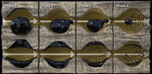
The technology has also displayed positive results outside of these ideal parameters. The process creates the phenomena of decreasing the size of oil globules trapped in the reservoir rock pore spaces into micro-oil droplets that can now flow through the rock matrix. This is accomplished by managing the biology and ecology of the reservoir by utilising certain in-situ microbial species. In oil wet reservoirs, the microbes dislodge trapped oil by positioning themselves between the rock surface and oil, therefore changing the interfacial tension where the rock, water and oil are found. The microbial action is instigated by feeding certain species already in the reservoir a carefully created nutrient package that induces these microbes to become hydrophobic and to surround and physically deform the oil into micro droplets.
The five process steps
The process starts with complexity in laboratories but ends with a field application that does not require any capital expense. Extensive field equipment and onsite 24/7 factories, pipelines and tanks are no longer needed to recover tertiary oil. The five steps of the Organic Oil Recovery process are as follows:
Ì Field screening of reservoir characteristics. A one-page questionnaire is filled out by the oil operator. After reviewing a field’s technical characteristics and field maps, it is then advised to choose three or four pilot wells to test.
Ì Laboratory/DNA analysis. The next step is to collect water samples from each of the pilot wells. The water is then analysed for the ecology and biodiversity that is living in the reservoir water. From this inspection, various nutrient formulas are tested to inject into the reservoir to feed certain species of microbes.
Ì Pilot test – in-situ microbial response analysis (ISMRA). Each pilot well is tested with a specific nutrient formula created in the laboratory. This formula is what will induce the microbes to multiply in situ and then undergo a cellular change that will allow the microbes to become hydrophobic and move away from water and towards oil. This action creates micro-oil droplets.
Ì Targeted water flood implementation. The next step would be to apply a larger batch treatment to injector wells as a pilot.
Ì Full field application.
Middle East water flood application
For a project in the Middle East, laboratory analysis and imaging studies allowed for a nutrient package to be created for certain species that were resident in this reservoir.
Ì Within the process, slides are examined at medium to high power on a Nikon digital imaging microscope
Figure 2. Microbes living in the water become hydrophobic and move away from the water and rock towards the oil. They physically deform the oil into microdroplets.
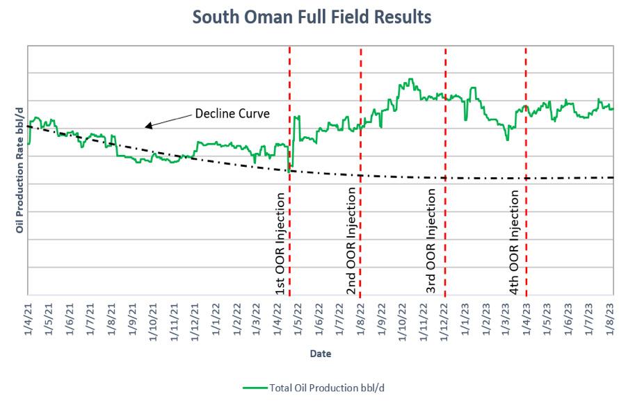
Figure 3. South Oman full field results.
Figure 1. The invisible world of microbes – a teaspoon of garden soil has 1 billion microbes.
which allows for the determination of the types, abundance and morphology of the microbes that have been affected and their growth rates.
Ì The lab analysis is used to develop a plan for a nutrient programme to be implemented in the reservoir. The objective is to see the proliferation of certain species that become hydrophobic. After introducing the formula into the reservoir, the well production is monitored by well tests as well as continuing water samples to follow the changes in the ecology. At this field, the water sampling showed order of magnitude increases to the targeted microbes that corresponded to the oil production increases. 1 ml (20 drops) of reservoir water could then contain 5 million microbes which would be naturally inclined to move towards the oil and deform it to micro droplets.
This field application targeted two injectors, supporting six offset producers that continued to have significant oil production increases beyond 16 months. The field had the following characteristics:
Ì Oil API ranges from 19.4 – 27, pH 7.54 – 7.75 and permeabilty ranges from 200 – 700 mD.
Ì Average reservoir temperature of approximately 55°C.
Ì Water salinity of approximately 12 980 ppm NaCl.
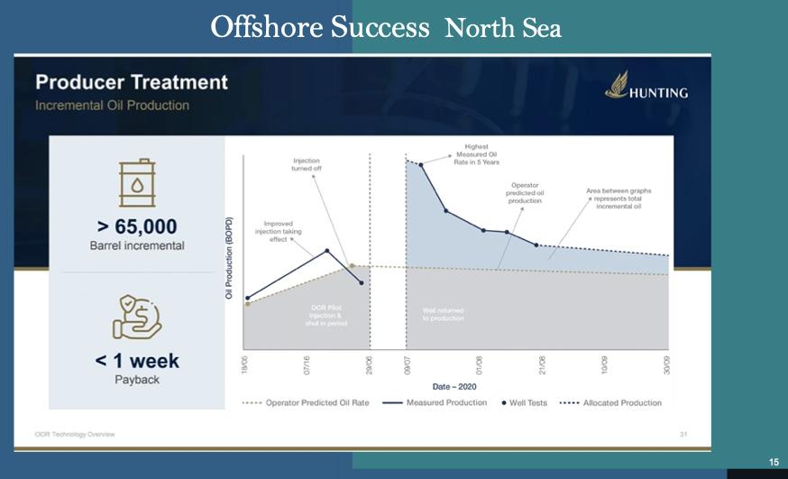
North Sea application
CNOOC was involved in a pilot study to determine the efficacy of the Organic Oil Recovery process as a means of maximising oil recovery from its Scott field in the North Sea.
CNOOC’s operated Scott asset came on stream in 1993 and produces crude oil and natural gas from the Scott, Telford and Rochelle fields. Scott is located approximately 188 km northeast of Aberdeen in 142 m of water.
The process, which harnesses microbial life already present in oil-bearing reservoirs to improve oil recovery, was chosen by CNOOC to pilot on the Scott platform. The process was expected to be successful after laboratory testing showed a positive microbial result that indicated changes in interfacial tension would occur to increase the oil’s mobility and improve recovery rates on the Scott pilot well. These changes could increase recoverable reserves and extend field life through improved oil recovery with negligible topside modifications.
The pilot programme was implemented by injecting a specific nutrient blend directly at the wellhead with ordinary pumping equipment. The well was then shut-in for an incubation period of 10 days and thereafter returned to production.
During the initial laboratory testing of two Scott target wells, the reservoir showed a diverse and abundant resident ecology which has been proven capable of undergoing the necessary characteristic changes to facilitate enhanced production. The pilot test was completed on a well in July 2020 and due to this application, both an ecology and dramatic production response was seen. In addition to this response, a drop in H₂S in both the oil and gas phase was observed and has continued until at least the last test in late 2023.
Conclusion
Using a proprietary science of microbiology to manage the biology of oil reservoirs can be an effective low-cost oil recovery process that can increase oil production,
lower water cut and lifting costs and increase the recovery factor of mature fields.
This technology can be utilised with no capital expenses and without the long time frames of implementing other forms of enhanced oil recovery that sometimes take 2 – 5 years. The Organic Oil Recovery process is biodegradable and allows oil operators a low cost, low risk, and low carbon method of enhanced oil recovery.
*Base test fluid consisted of 9.2 lb/gal NaCl brine, 0.25 lb/bbl soda ash, 0.25 lb/bbl caustic
Figure 4. Specific increases in number by 100 –1000 times.
Figure 5. Offshore well doubling production.
Table 1. Offshore North Sea.
Azka Yasyfa, James Fisher AIS, Indonesia, explores how the country is utilising
digitalisation within its energy industries.
Spanning over 735 000 square miles and 17 000 islands, Indonesia is the world’s largest archipelagic state whose waters hold a rich oil and gas heritage. Once a leading exporter, the country reached peak production in the 1990s1 and the nation’s vast expanse now exacerbates energy security challenges and an ever-quickening need to transition to cleaner energy sources.
Navigating a complex landscape
However, over the last few decades, the country has faced challenges such as declining reserves, an ageing oil and gas infrastructure, and regulatory issues, leading to a decrease in oil production and a shift towards natural gas, as a lower emissions alternative.
Oil and gas will continue to play a major role in Indonesia’s varied energy portfolio ensuring domestic energy security, but to continue to do so, certain challenges will need to be addressed. The decline in production is owed to the country’s particular set of challenges, such as investment frameworks, field development solutions and the balance between national and private entity interests. Introducing digital solutions that deliver increased efficiencies can therefore prove to be challenging.
Interconnecting islands with digital waves
What is key to solving this problem is an awareness that digitalisation could provide a solution to a sector with many data silos. Digitalising operations can bring a whole host of benefits such as reducing asset downtime and improving worker productivity and on-site execution efficiency, by bringing together data that helps to paint a vivid picture of an asset’s real-time status.
Making the invisible visible
In Indonesia, assets are typically in very remote locations with limited data connectivity. Modern digital systems can support the rapid integration of data to allow engineers and managers to instantly visualise the reality of the situation without wasting time on lengthy data gathering activities. Centralised digital systems can bring together asset data from the most remote corners of Indonesia, helping local oil and gas companies, as well as government entities which provide support and funding, to better understand the safety and operating status of energy hubs and assets within its operation.
Digitalised data is vital when dispersed teams are operating on the ground in different locations. From mobile phones to social media, digital technology connects us, helping to bring the disparate islands of the archipelago together.
Digital solutions providers on the ground across the islands can help Indonesian energy producers access enriched views of their assets through centralised, digitalised systems of data management. Pin-pointing exact anomalies, faults and risks, this real-time overview of an ageing infrastructure, in remote and unforgiving environments, can plug the gaps in operations.
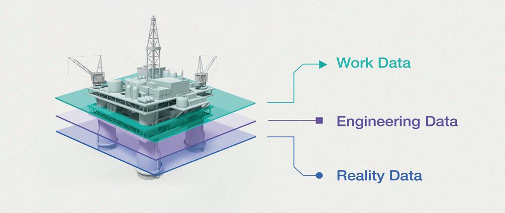
With even newer technologies like digital twins, Indonesian operators can access reality data, helping them to monitor assets and operations across the archipelago. Through this, pre-planning of maintenance, as well as the delivery and quality assurance of major projects, play a large role in the broader regional energy context. Additionally, some digital twin software models can connect site imagery to existing data to give operators a detailed view of their assets. For Indonesia’s ageing infrastructure, this could provide significant opportunities to maximise output as the assets degrade.
Fuelling progress with collaboration
Whilst digitalisation might plug the gaps and connect the dots, just as it connects dispersed asset data, companies can still be wary of taking the risk to invest in the search for a return on investment. However, the
opportunity to deliver more value from assets remains. By partnering with software companies – those with local, geographical and historic knowledge of sites, to support exploration, drilling and production –national oil companies (NOCs) and smaller, local energy production companies in Indonesia can find their operations vastly maximised.
Hesitancy to change can be common, particularly when the stakes of energy security – a key concern of NOCs – are high. For this reason, digital solutions providers looking to make headway in the region need to consider adapting their approaches, building bridges with flexibility in mind.
Met with wariness in some instances, these companies will be wise to take local nuances into consideration. Historically, long-lasting partnerships across the industry have been fostered through consultative-style processes. Through this, confidence is built, trust is instilled, and progress is made.
By being adaptable, Indonesia’s oil and gas companies can have renewed confidence in adopting innovative technologies such as digital twins, data analytics, and predictive maintenance, by making smaller changes in the first instance, and then building on top of that success.
This model could mean that Indonesian energy companies are keener to adopt advanced technologies like data analytics and predictive maintenance, ultimately bolstering their operations. With this growth, seeing a return on investment should instill further confidence in these partnerships and technologies, giving Indonesian firms the option to scale operations and adoption.
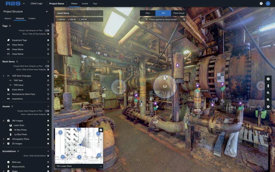
The proof has been in the pudding, with companies who have already adopted this digital approach. With digital twins providing access to reality data, Indonesian operators have eyes on assets and operations 3000 km away, making the invisible, visible. This has already been done at a remote LNG production facility in Indonesia, where James Fisher AIS’ R2S digital twin meant that the team could cut down on the 20 hours of flight time and boat journey to reach the facility from the nearest hub city, as well as increase collaboration across the dispersed team.2
Anticipating tomorrow
With Indonesia taking its rightful place in the global energy transition, the nation’s historic prioritisation of energy security over exportation could be set to change. Joint agreements made with Japan in December 2023, the Philippines in January 2024 and committed geothermal and hydro targets, showcase its clear ambitions for renewable growth. 3 – 5
With this, Indonesia ensures that in the future, lower carbon intensity energy sources also have a part to play in both the energy transition and energy security of the region, but these too will require careful inspection and monitoring.
Whether it is in the fields of oil and gas, or geothermal and natural gas, it is clear that digital solutions and flexible business models which put energy companies and their pain points first, will be key to achieving these.
Figure 2. The digital twin powers performance by presenting work data, engineering data and reality data in a real-world context to plan better and make decisions faster.
Mojtaba Moradi and Mike Konopczynski, TAQA (Industrialization & Energy Services Company), UK, and Geir Frode Kvilaas, Aker BP, Norway, discuss how AOCDs can enhance well efficiency and reduce the costs associated with intervention and maintenance while providing data for future well completion projects.
Finding the
Balancing the benefits of increased hydrocarbon recovery with the environmental and safety challenges associated with injection wells is crucial for ensuring long-term efficiency and viability. Several techniques, such as passive flow control devices, have been applied to improve the conformance of injection wells and enhance oil recovery. However, their success is limited in reservoirs with complex/dynamic properties, including propagating/dilating
the balance
fractures, which can potentially lead to water short-circuiting to nearby producer wells.1 – 3
New autonomous outflow control devices (AOCDs) enable operators to implement an optimum reservoir drainage strategy that uses downhole control which can be manipulated autonomously based on well-dynamic conditions. This greatly enhances well efficiency and reduces costs associated with intervention and maintenance while providing valuable data for future well completion projects.
Enabling EOR from injection wells
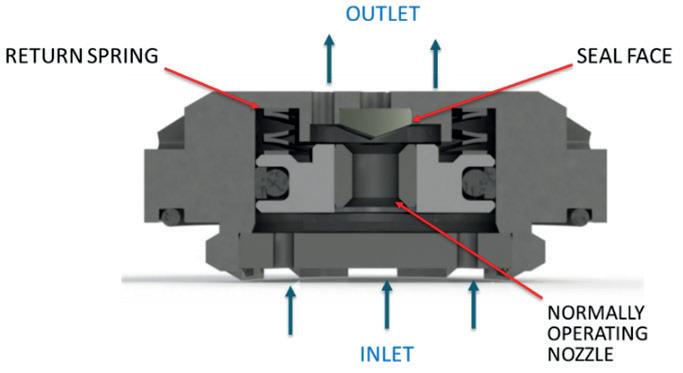
FloFuse, developed by TAQA, has been successfully installed in more than a dozen campaigns worldwide to control faults, natural and thermal fractures, and high permeability zones for the injection of water, gas, acid and polymer in both carbonate and sandstone reservoirs. The autonomous, bi-stable active flow control device has two operating conditions, firstly as a conventional flow control device, and secondly, as a barrier when the flowrate through the valve exceeds a designed limit.1 At the second flow condition, the denied fluid to that specific zone will be distributed among the neighbouring zones. This prevents excessive fluid injection into the thief/fracture zones and maintains a balanced fluid distribution across the full targeted injection zone.
Figure 1 depicts the cross-section and key elements of the device, which is a spring-loaded, open injection outflow valve designed to limit the flow area to specific zones when a prescribed tripping flow rate is exceeded.
The valve is fully reversible and will reset if the flow rate becomes sufficiently distributed again. The target normal operating rates, degree of outflow control, and trigger rates can be adjusted based on the application. Like other ICDs completion, these devices should be installed in several completion zones in the well by annular flow isolation tools like swell packers to provide independent control to each layer.
Importantly, this technology eliminates the need and cost of running an internal lifting tool (ILT) and the complex well interventions required to open/close integrated sliding sleeves (if available) in traditional completions, enabling optimised well performance autonomously.
Since it was introduced in 2019, field results have proven the success of AOCDs both in terms of achieving the target injection profile and controlling the thief zones as exemplified in the following four case studies: 4 – 7
Sandstone reservoir –offshore Norway
The rate limiting flow control device was recently deployed for the first time in the
Figure 1. Cross-section of AOCD valve.
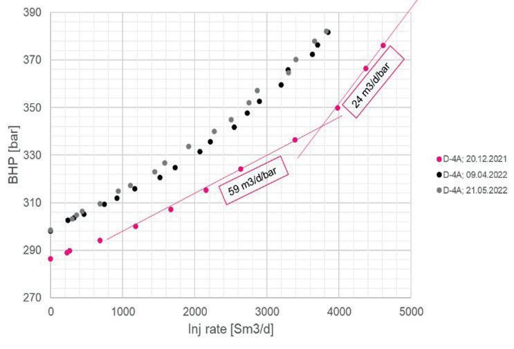
Figure 2. Bottom hole injection pressure vs injection rate behaviour with AOCD completion.
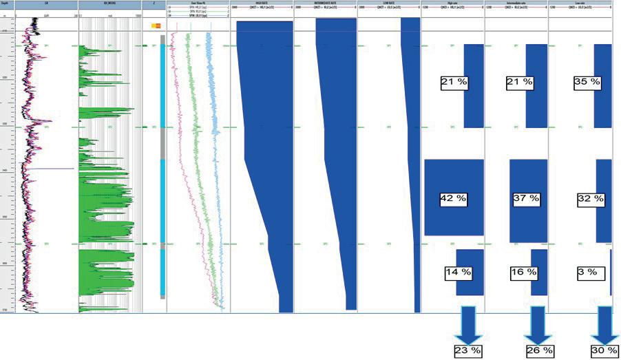
Figure 3. Injection logging tool (ILT) for the well with AOCD completion.
Ivar Aasen field, located in the northern part of the North Sea, 175 km west of Karmøy, at 110 m water depth. Discovered in 2008 and operated by AkerBP ASA, there are 11 horizontal producers and eight injectors on the flanks with data from five wells drilled prior to the development wells in 2015.8
High outflow rates through high permeability streaks had increased the potential of unwanted early water breakthrough from injector points to production wells. AOCDs were applied on two hybrid wells to optimise the performance and efficiency of water injection operations by maintaining injectivity along the well, ensuring uniform injection distribution, and improving sweep efficiency in the reservoir.
The results from several well performance data, including injection logging tool (ILT) data as well as several multi-rate tests, confirmed that the applied completion design had achieved the objectives of the project. For instance, the multi-rate test, normally used to establish the injectivity index, shows a significantly different Q vs P profile compared to conventional completion (Figure 2).
The data shows that even with high injection pressures, the injection rate data does not indicate development or growth of fractures that would normally be expected with conventional completion.
In addition, injection logging was carried out at three distinct injection rates: a high-rate of 3000 m³/d, a mid-rate of 2000 m³/d, and a low-rate of 1000 m³/d. The results revealed flow across all devices and along every completed interval, with an injection contribution of 25 – 30% through the flapper plug (Figure 3).
In contrast to the variations observed at higher rates, a more consistent outflow distribution was observed at the low injection
rate within each swell packer interval. However, uncertainties arose regarding the low rate on the interval spanning from 3560 m MD (measured depth) to 3660 m MD, with the potential for injection contributions reaching as high as 8%, as indicated by down-pass analysis. Conversely, the outflow distribution remained relatively similar at high and intermediate injection rates.9
Onshore carbonate reservoir – Middle East
Drilled in 2012 and completed as a dual injector, Well A had a short string injecting water into the upper zone of reservoir B and a low string injecting water into the lower zone. The short string was perforated, while the lower zone remained a 6 in. open hole with a total length of 2963 ft and a 90° inclination. The primary goal of water injection into these layers is to maintain reservoir pressure, with three additional nearby wells also injecting water into reservoir B3 .
A PLT discovered that the well had been injecting water into the limestone reservoir for several years, indicating the existence of major faults and ant-tracks. Higher injection rates were observed in depths 10 000 –10 300 ft due to geological features which accounted for approximately 36% of water injection.
In 2020, nine 4½ in. AOCD joints, five joints of bypass high pressure ICDS and five swellable packers for compartmentalisation and zonal isolation, were installed. The well was divided into six compartments based on fractures/ant-track depths. Injection resumed at the target rate of 3000 bwpd.
By comparing PLTs from 2014 and 2021, it was confirmed that the injection rate into the zones with faults and ant-tracks had been reduced by 42% while an increase of 20 – 25% in water
injection was achieved in the other zones with no suspected faults and very low injectivity.
As the valve autonomously reacts to changes in reservoir conditions, the comparative analysis demonstrates how AOCD technology can manage uncertainties in reservoir properties while delivering optimised well performance. As a result, the overall sweep efficiency in the well has been significantly improved. Moreover, water injection contribution along the horizontal section of the hole was enhanced.
As these valves could be used to function as mechanical diverters, an acid stimulation operation is planned in the wells to help improve the injectivity of zones with low permeability and remove any skin accumulated over years of injection. This would greatly improve the water injection conformance of the zones further.
Complex wells – offshore China
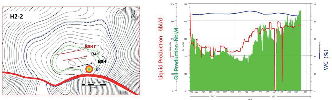
To maximise the production and injection capacity of several wells offshore China, AOCDs were installed to perform three operations using one wellbore, simultaneously. The longer string allowed oil production from the deepest reservoir, while the shorter string would be used to produce water from the shallowest reservoir, thereby, re-injecting water down to another reservoir without bringing water up to the surface. However, controlling fluid influx and outflux for each section of well B4H1 was critical as the reservoir management plan required that prescribed injection profiles were maintained.4
The injection was planned at the middle section of the well which was normally comprised of a few separate sub-layers. However, the expected properties of the sub-layers were not in line with the desired (target) injection allocation. For instance, the first layer was
expected to intake 75% of the flow. To deliver the desired injection profile over the well’s lifetime, each section was divided into several completion zones, separated by swell packers, with an appropriate number of AOCD installed on the screens. Based on the reservoir management plan, analysis of nearby production wells showed the devices had managed to achieve the prescribed injection profile to these sub-layers supporting the nearby wells.
For instance, following the initiation of water injection into this layer, well B4H1 experienced a substantial enhancement in production with a daily oil production surge of 32 SM3/d (Figure 4). By October 2023, the cumulative net oil increase reached 5.4 kSM3, and a projected net oil increase of 17.6 kSM3 over the well’s lifespan is anticipated. Similar increments have been observed in other wells at other layers.
Polymer injection wells – Oman
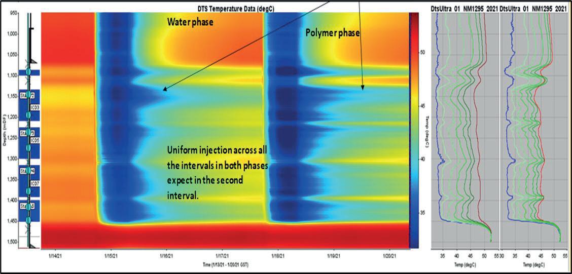
In 2020, a major operator in the Middle East undertook its first trial of AOCD technology in a new long, horizontal injection well in a heavy oilfield in Oman. This successful application was then extended to other injectors in both water and polymer phases in the field.
The well had seven zones of completion with only five of them to be completed. The main objective was to maintain a balanced injection distribution in case of injectivity changes in one or more zones due to initiation of fractures.
While the target injection was set to 350 m3/d of polymer into the reservoir, the well model covered several scenarios and sensitivity cases of fracture initiation in different zones. A total of 13 AOCDs and nine bypass valves were used to complete the five compartments. Bypass valves allow the autonomous device to re-open again after it triggers, should the injection rate drop below the tripping rate, and to provide minimum injectivity required in each zone should several valves trip at the same time. The compartments were segmented using pre-designed swellable packers with feedthrough capabilities to allow the fibre optic cable to pass through for monitoring purposes.
To ensure a comprehensive set of deterministic information and monitor the performance of the device, DTS was installed along the completion. Figure 5 illustrates the results and interpretation of the second DTS analysis during both the water and polymer injection phases.
The results showed that almost 93% of the desired conformance was achieved by AOCD completion.
The campaign was considered a ‘game changer’ by the operator, with good oil gains of approximately 23 m3/d from four nearby oil producers. With this improved conformance, it is
Figure 4. The injection well and nearby production wells’ location in the middle layer (left). Production profile of well B4H1 (right).
Figure 5. Second DTS results under water and polymer injection.
expected to realise better sweep in the reservoir, resulting in improved oil production for the nearby supported producers. The plan is to deploy the technology as a baseline for all future horizontal polymer injector wells drilled for polymer fields to reduce the cost of stimulation and PLTs.
Enhanced environmental protection
The installation of AOCDs enabled operators from the four case studies to implement an optimum reservoir drainage strategy to manipulate and autonomously manage flow in relation to fluctuating well conditions. In all cases, the advanced completion technology successfully delivered the target rate and desired conformance performance to sustainably enhance well efficiency and reduce costs associated with intervention and maintenance, as well as providing valuable data for future well completion projects.
The characteristics of the device make it an ideal completion for a range of injection operations, including water and polymer injection wells, acid injection stimulation operations, as well as water alternating gas (WAG) operations, geothermal wells and CO2 injection/storage wells. In storage applications, particularly in CO2 wells, the device could play a crucial role in ensuring injection conformance and minimise risks related to compromised caprock integrity, thereby, preventing containment loss to zones above while eliminating crossflow.
References
1. MOHD ISMAIL, I. ; KONOPCZYNSKI, M., MORADI, M., “A Game Changer for Injection Wells Outflow Control Devices to Efficiently Control the Injection Fluid Conformance.” Abu Dhabi International Petroleum
Exhibition & Conference, Abu Dhabi, UAE, November 2019. https://doi. org/10.2118/197612-MS
2. MORADI, M., and TODMAN, S., “The Dynamic Performance Evaluation of the New Generation of Outflow Control Devices Autonomously Controlling the Conformance of Injection Fluids.” SPE Conference at Oman Petroleum & Energy Show, Muscat, Oman, March 2022. https://doi. org/10.2118/200177-MS
3. MORADI, M., and KONOPCZYNSKI, M., “The New Flow Control Devices Autonomously Controlling the Performance of Matrix Acid Stimulation Operations in Carbonate Reservoirs.” SPE Annual Technical Conference and Exhibition, Dubai, UAE, September 2021. https://doi. org/10.2118/205975-MS
4. AL HARRASI, A., MASKARI, M., URDANETA, G., AL-JUMAH, A., BADI, S., BUSAIDI, I., HARTHY, K., ABAZEED, O., and MORADI, M., “Autonomous Outflow Control Technology AOCD in New Water/Polymer Injectors in Heavy Oil Fields from South Sultanate of Oman.” Abu Dhabi International Petroleum Exhibition & Conference, Abu Dhabi, UAE, November 2021. https://doi.org/10.2118/207361-MS
5. AL SHEMAILI, S,I., FAWZY, A,M., ASSRETI, E., EL MAGHRABY, M., MORADI, M., CHAUBE, P., and MOHAMMED, T., “The New Generation of Outflow Control Devices Autonomously Controlling the Conformance of Water Injection Well - A Case Study with ADNOC Onshore.” Abu Dhabi International Petroleum Exhibition & Conference, Abu Dhabi, UAE, November 2021. doi: https://doi.org/10.2118/207647-MS
6. AL HARRASI, A., BADI, S., URDANETA, G., RAMLI, M., KINDI, S., Sinani., YOUSUF., and HARTHY, K., “A Polymer Flood Pilot with Autonomous Outflow Control Device Technology and Resilient Cost Management from South Sultanate of Oman.” ADIPEC, Abu Dhabi, UAE, October 2022. https:// doi.org/10.2118/211438-MS
7. Al HASHEMI, M,S., .“Fiber Optic Surveillance for Water and Polymer Conformance Monitoring in an EOR Project in Petroleum Development Oman.” ADIPEC, Abu Dhabi, UAE, October 2022. https://doi. org/10.2118/211477-MS
8. KVILAAS, G,F., MORADI, M., “The Initial Applications of Autonomous Outflow Control Devices in Water Injection Wells in Norway“. DEVEX, June 2023 https://doi.org/10.2118/218473-MS
9. XIONG, S., CHENG, J., REN, F., MORADI, M., “Application of Autonomous Outflow Control Devices to Optimise Water Injection in Triple Functionality Wells: Case Studies in Offshore China” OTC Asia 2024, Kula Lumpur, Malaysia, March 2023. OTC-34658-MS, https://doi. org/10.4043/34658-MS
Samarium Cobalt Grades 18-35E NdFeB
Neodymium Iron Boron Grades N28 - G57
From Ticking The Box To Becoming Top Notch From Ticking The Box To Becoming Top Notch
Dave
Cormack, 3T Energy, UK, discusses the recent advancements in well control training.
When a well control issue occurs, it needs quick and effective action from rig personnel to prevent potential disaster. That is why well control training is critical, and certification needs to be renewed every two years in order to mitigate against skills and knowledge fading and assure worker competency. But how can both rookies and seasoned professionals stay engaged and benefit from the training in mixed-ability classes? It is a challenge that technology is now helping the industry to address.
In any well control school, instructors can be faced with a range of differing levels of experience and learning abilities. With an extensive set curriculum to get through, instructors need to ensure all delegates remain engaged and take something valuable from the training.
Tailoring training to each individual’s learning style and experience level is key, and technologies such as simulators and mobile apps are helping to deliver differentiated learning, building individual competencies regardless of the experience of the rest of the class.
Within well control, hands on time is extremely important. Numerous studies show the importance of human factors in drilling and any training needs to consider situational awareness, decision-making, communication, and similar methodologies to deliver the best training experience.
Perhaps the most effective tactic is active learning. Allowing students to actively carry out activities and mirroring the operational tasks they will face in the field can embed knowledge and improve memory retention.
Advanced simulators enable people to have this ‘hands on’ time before even setting foot on a rig, and that it is important to
ensure delegates get plenty of hands-on, instructor-led classroom simulator time.
The emergence of well control training
This technology is a far cry from the early days of oil production. At the turn of the 20th century, drilling technologies and equipment were very simple. Drillers had no real control over the well when drilling into high-pressure zones.
As a result, the drilling industry was very hazardous with blowouts being fairly regular occurrences, killing crews, destroying equipment and polluting the environment.
Drilling techniques improved over time and control over the well was gained by using fluid of a sufficient density (weight) to exert a pressure
down the well that would stop the formation from kicking and becoming a blowout. To this day, the primary means of maintaining control over a well being drilled is through the use of drilling fluid hydrostatic pressure.
Well control equipment has also improved over time, and through experience, people have improved well killing techniques. During this period, there was no real training in well control techniques, as such – it was passed by word of mouth.
Formal training started in the US in the early 1980s and in Europe, the search for common standards in well control training culminated in the formation of the European Well Control Forum (EWCF) in 1992, which evolved into the International Well Control Forum (IWCF).
The IWCF syllabus required a practical demonstration of competence on a simulator in addition to theory papers.
Simulators had arrived and well control training started to become unified and more relevant – particularly when the subsea element was included.
Gaming influences
Originally, drilling simulators used the same simulation engines as the military but this became too restrictive; simulators more commonly now use the latest gaming engines.
The latest generation of simulators has ultra-realistic graphics, simulation fidelity, highly immersive scenarios and avatars with the ability to influence events on the screen.
This ensures today’s simulator training experience is highly immersive, allowing students to learn in scenarios that feel lifelike. It looks and feels like being on the drilling floor. But unlike being on the drill floor, students are able to face situations they may never encounter in the real world and train for them to become fully competent.
As well as highly advanced simulator technology helping to improve the training experience, gaming-inspired mobile apps can also help improve pass rates for the notoriously difficult IWCF exam.
As well as making information relevant to the individual’s own experience, repetition can help the brain to recognise that the repeated information is important. Micro-learning in short bursts is a good example of this, and something the developers should consider when creating learning apps.
Apps can reinforce learning and knowledge through short quiz-based ‘workouts’.
3T’s app uses artificial intelligence, graphics and the addictive and competitive qualities of gaming to embed learning on IWCF’s (International Well Control Forum) drilling and well control courses.
Delegates attending IWCF courses are being offered use of the R3 app, which stands for ‘read, repeat, retain’, to support their learning.
It uses a premise of a two-minute quiz-based ‘workout’ for people to complete every morning on a mobile phone to improve knowledge and embed critical information. The ‘workout quiz’ uses topics covered on the IWCF course to
Figure 1. Simulator training in action.
Figure 2. ‘On the rig’ (OTR) simulator.
maximise knowledge retention. Instead of a chore, the app hopes to make training more fun and an ongoing activity to help with memory retention.
All of the delegates who have used the app have successfully passed the course. The importance of tailoring training to the individual has long been acknowledged.
Five levels
In 2016 The International Association of Oil and Gas Producers (IOGP) published a report recommending enhancements to well control training to ensure training is adapted to better suit the individual and that scenario or simulator-based training complements existing training.1
Over the past 12 years, it is clear that these recommendations have been incorporated into mandatory well control classes and five levels of well control training have been introduced to ensure training meets the needs of every individual and every role. The five levels of well control training are as follows:
Ì Level 1 – well control awareness training. This provides an entry point of training for drilling operations crews, as well as providing some background understanding for those not immediately involved in the control of a well but who may be involved indirectly. Examples of personnel in these roles include logistics personnel, supply and support vessel personnel, and drilling related service hands.
Ì Level 2 – drilling and wells personnel basic well control training is intended to start preparing those who could directly affect well control response. Personnel requiring this level of training include some junior drill crew positions, rig-based marine personnel, mud logging crews and service company supervisors. This training is much more well control specific and is assessed via a pass/fail exam.
Ì Level 3 – driller well control is the requirement for anyone in a job position that may require them to shut in a flowing well – normally drillers and assistant drillers. At this level, simulator training forms
a key part of the training and the final assessment must include a practical assessment.
Ì Level 4 – supervisor well control training is primarily aimed at wellsite supervisory personnel and office based well design and operations personnel. Content for this level includes more advanced training in well monitoring, kick detection, and kill methods. Once again there is a role-specific practical assessment on a simulator, which forms a key part of the final assessment process.
Ì Level 5 – engineer well control is very much aimed at those responsible for well design with a strong focus on the well design process and selection criteria for equipment. This training can be delivered as part of a planned self-study programme and via attendance at a classroom-based training course. This training also has a pass/fail assessment but can be incorporated into a well engineering training programme.
Conclusion
As with all things in the drilling industry, well control learning is moving forwards. At the beginning of the last century, uncontrolled blowouts happened, and when they did, drillers learned very suddenly what it was all about. Nowadays, well control learning has become much more structured in its approach with the emphasis on proper development. It is also focusing in on the individual and becoming much more tailored to their needs.
Ultimately, this is very important. Technology is continuing to evolve and enhance learning for the industry, but as long as humans are involved at critical points in the system, then there remains an obligation to ensure that each individual is trained for their role in the best possible way.
References
1. www.iogp.org/pubs/476.pdf
We have supplied worldwide more than 200,000 parts to the industry per year for last 20 years, ensuring the complete product including all technological processes of production, surface finish, marking, packaging up to dispatch, and shipping to the destination according to the customer´s needs. We care about high quality products which we make in the Czech Republic from raw materials with origin in EU countries. Certificates for the basic material, measurement protocols, and other necessary documentation are a matter of course.
For any further questions/ inquiries, please don´t hesitate to contact us on e-mail below:
Czech Republic
OPTIMISING MUD LOSS PREVENTION
In an in-depth exploration led by a Chinese operator renowned for drilling in the shale-rich southwest region, a comprehensive situation unfolded. The primary objective was to look into the potential advantages of integrating smart equipment and wellbore-strengthening technology, to minimise, or ideally prevent, mud loss while drilling in challenging vertical sections within a troublesome formation. To achieve this, the study depended extensively on historical drilling and lithology data, and the implementation of real-time monitoring.
The identified problematic zone spanned between two formations, with a thickness ranging from 500 – 700 m, distinguished by the presence of microfractures. An analysis of past drilling activities within this formation unveiled the recurring challenge of mud loss incidents when using a mud weight of 1.86 specific gravity (sg). The loss rates during these instances fluctuated from 0.13 – 0.19 m3/min, resulting in significant direct economic losses attributable to drilling mud. The recorded mud losses per well varied
Qi Liu, CNPC Chuanqing Drilling Engineering, and Jack Wang, Vertechs Group, China, explore the advantages of integrating smart equipment and wellbore-strengthening technology while drilling in challenging vertical sections.
from 300 – 600 m3. Stopping drilling operations and adjusting the mud weight to 1.76 sg proved ineffective, escalating well control risks in some wells. Traditional measures like pumping down lost circulation materials were time-consuming, leading to extended non-productive time (NPT) and increased costs. Additionally, these measures had minimal impact on bridging the microfractures within the formation. Without appropriate preventive and remedial measures, drilling a new well within this formation was destined to incur varying degrees of mud loss.
Despite these challenges, the operator implemented cost-effective solutions to maintain a normal drilling process and avert mud loss in real-time. One particularly effective technique involved adding wellborestrengthening nanoparticle additives into the active drilling mud before entering the trouble zone, maintaining an optimal concentration throughout the drilling process. This additive formed a low-permeability filter cake on the wellbore, bridging microfractures encountered without disrupting drilling operations. The correct concentration of the
nanoparticle additive was maintained at an optimal dosage, ensuring proactive prevention of mud loss. In this specific case, an initial 5000 kg of nanoparticles were added into the active mud, resulting in a total concentration of 2% for maximum effectiveness.
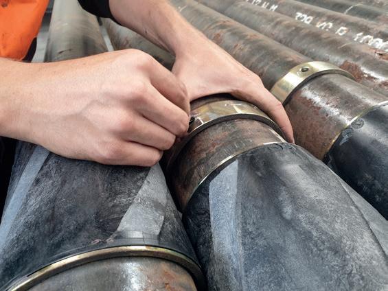
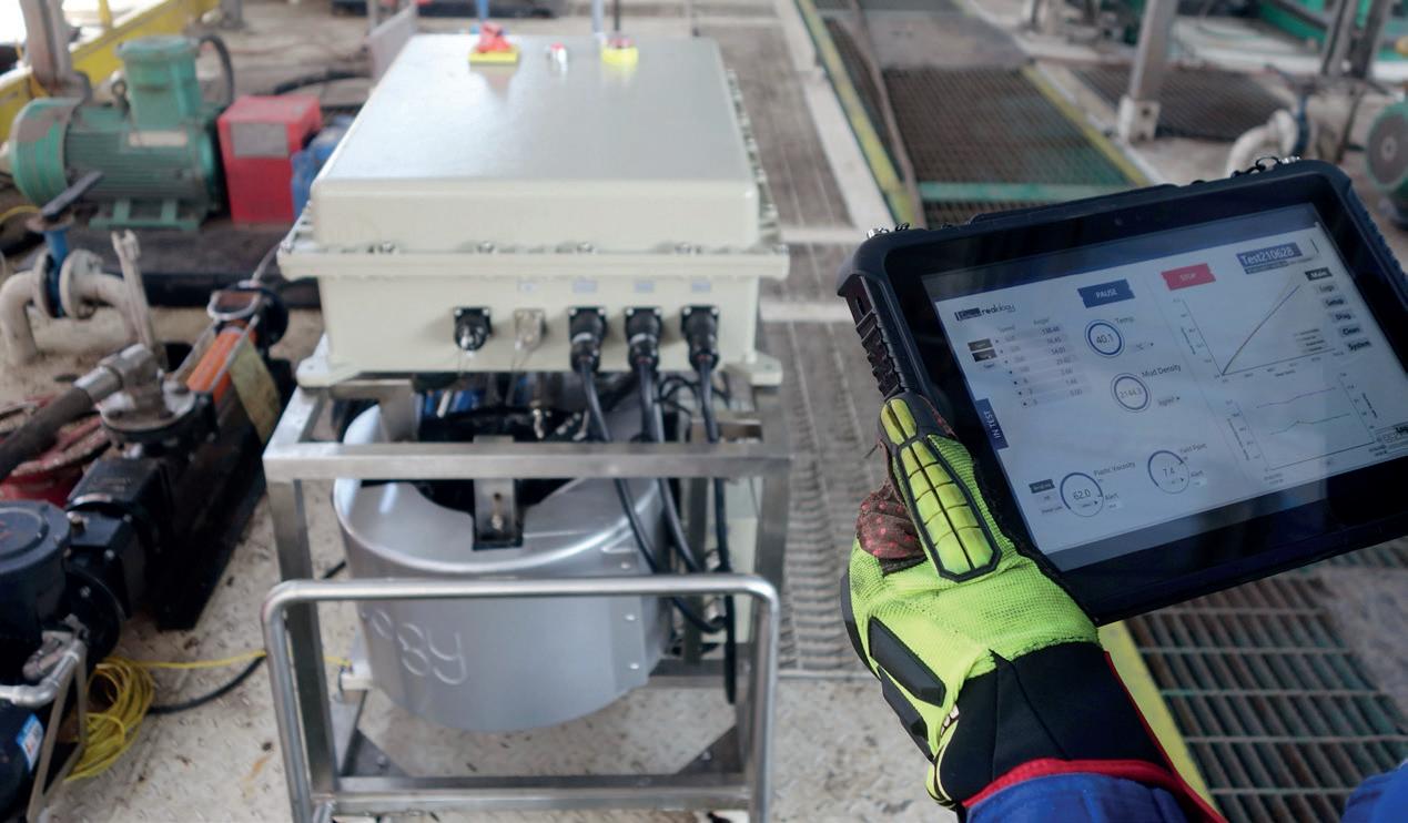
To provide real-time monitoring of the performance of drilling mud and the effective concentration of nanoparticle additives, the operator implemented smart equipment. A wireless portable concentration tester was used to test the effective concentration of the nanoparticle additives, and an autonomous drilling mud rheology monitoring device was used for monitoring crucial drilling mud properties. This device enabled real-time monitoring and data collection of key parameters, including
density, viscosity, temperature, and the presence of various chemicals and contaminants.
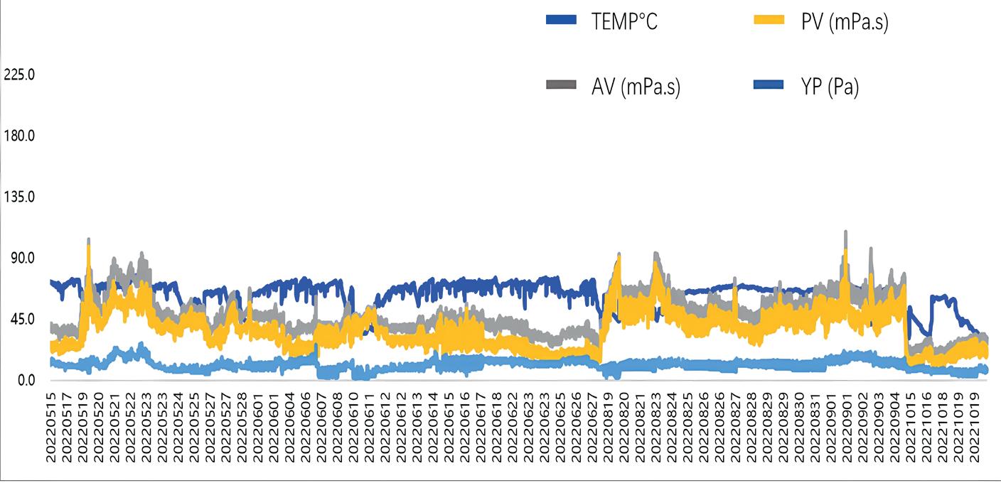
One significant reason for utilising smart equipment for real-time monitoring is to prevent adverse effects stemming from an excessive amount of nano additives in the mud system. The rheological properties of the drilling mud can be altered if an excessive quantity of nano additives is introduced. This is likely to happen, potentially due to human error, as field engineers add these nano additives into the mud. In this case, the plastic viscosity and yield point of the drilling mud are closely monitored with a high frequency of one data set per 10 minutes, compared to traditional manual tests performed only twice per day. Moreover, it is essential to keep key rheological parameters within an optimal range throughout the drilling process. Real-time monitoring of these critical parameters also ensures accurate calculations for equivalent circulating density (ECD).
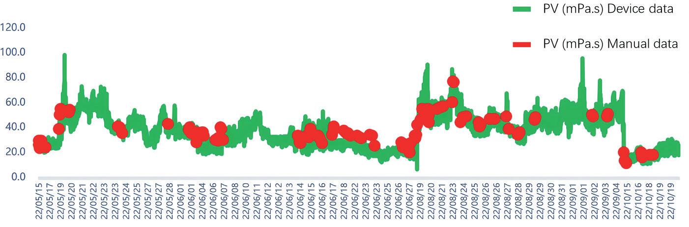
In contrast, traditional methods of monitoring and controlling drilling fluid properties relied on manual approaches such as visual inspection, laboratory testing, and manual adjustments, known to have certain limitations. While manual methods can yield satisfactory results, they are generally less precise and accurate compared to the automated sensors utilised by smart equipment. Moreover, manual methods tend to be time-consuming and labour-intensive and lack the capability to provide real-time data. Another significant advantage of employing smart equipment is the reduction in the risk of human error. Automated sensors eliminate the potential for inaccuracies caused by human factors, ensuring more precise, frequent, and reliable data input.
Conclusion
The integration of data analytics and smart equipment stands as advancement in the drilling industry. This case study serves as evidence of the effectiveness of proactive measures, guided by historical data and executed in real time, not only effectively tackling challenges, but also paving the way for heightened efficiency, safety, and future optimisation in drilling operations. Automated systems provide immediate data on rheological parameters, allowing drilling operators to maintain fluid composition and properties for optimised performance. This real-time data facilitates prompt adjustments, reducing downtime associated with fluid-related issues. The elimination of potential human errors in data collection and interpretation is another crucial advantage of automation. Furthermore, remote monitoring of rheological parameters diminishes the need for personnel to be in close proximity to drilling operations, thereby mitigating the risk of accidents and exposure to hazardous materials. Smart equipment’s ability to log and store historical data over time enables in-depth analysis of drilling fluid performance, aiding in the optimisation of drilling strategies and fluid formulations for future projects. The remote accessibility feature proves particularly valuable for providing guidance and support from offsite locations, especially in complex drilling operations in remote or challenging environments.
Figure 1. Monitoring and tracking parameters in real-time, including density, viscosity, temperature, and the presence of various chemicals and contaminants within the drilling fluid.
Figure 2. An exported file from the data log displaying variations in drilling mud rheological parameters throughout the entire drilling operation.
Figure 3. The trends of PV data, depicted by a green line and red dots, exhibit substantial overlap. The frequency of manual tests is notably lower compared to the frequency of data generated by the device.
The print issue is distributed to a global audience of industry professionals (verified by ABC). Register to receive a print copy here: worldpipelines.com. magazine/world-pipelines/register
Prefer to read the issue online? The digital flipbook version is available here: worldpipelines.com/magazine/world-pipelines
Frank
Wurpel, Adaptive Process Solutions (APS), UK, outlines why many produced water treatment systems for ageing assets are no longer fit for purpose, and explores the different solutions available.
As a result of increasing water cuts for maturing oil production installations, produced water separation systems have become progressively more challenged in terms of oil in water removal performance. In many instances, this creates a water bottleneck which can cut back an installation’s crude oil production.
Most North Sea production facilities were originally designed for well fluids with a relatively low water cut. Over the decades, the oil/water ratio has gone full circle, with many mature installations now producing very high water cuts from existing wells. This is further exacerbated by the drilling of new wells and new fields being tied into existing installations, resulting in even more water.
Environmental concerns and rising production costs
As the separation of oil from produced water flow mostly relies on gravity separation, an increase in the overall throughput of produced water will directly
result in a reduction of residence time in separating vessels and consequently a higher oil in water (OiW) content in the water discharged overboard or reinjected.
Processing this additional water within the 30 parts per million (ppm) permitted discharge consent leads to produced water processing constraints and the need to choke back or close in high water producing wells that also produce hydrocarbons. This ‘bottlenecked’ production increases the lift cost per barrel of oil and is further compounded by the increased cost of maintaining ageing assets.
The answer to how this could be resolved is relatively simple – if the throughput of the fluid process capacity can be
increased by debottlenecking water processing, the lifting cost per barrel will be reduced.
Status quo: one size fits all is no longer a solution
Almost all produced water treatment systems consist of hydrocyclones and downstream polishing vessels, such as a settling tank, and/or induced or dissolved gas flotation units. Although the separation methods are well understood and proven, the current performance of these units is rarely optimal, because they are operating out of their optimal operating efficiency window. This is especially true for gas flotation assisted gravity separation vessels.
While all separation techniques are important in the total OiW removal efficiency of the produced water treatment plant, gas flotation is frequently used as the final stage in the oil from water removal process. However, the gas bubble size that was set when the installation started operations may no longer meet today’s requirements, but cannot be changed.
Because the produced water discharge stream from the hydrocyclones contains both low concentrations of oil droplets and often very small oil droplets, removal of droplets and fines can be extremely challenging.
While small oil droplets in high concentration will normally interact and coalesce to increase the median droplet size, the normally low concentration of oil downstream the hydrocyclone reduces this probability. A standard gravity separation vessel would therefore need to have a very long residence time to achieve the desired OiW reduction efficiency. For this reason, gas flotation is often used to promote oil droplet buoyancy, decrease required residence time and consequently increase produced water flow rate.
Gas flotation systems currently installed have no control over gas quantity and gas bubble size and use the one-size-fits-all ‘buckshot’ approach, which will not yield the desired results.
For an oil/water separator to function properly, the oil must be given sufficient time to reach the liquid surface. The main objective of gas flotation is for a gas bubble, which has greater buoyancy, to attach to an oil droplet, and drag it to the surface quicker.
But as oil droplets are not uniform in size, the ‘one-size-fits-all approach’ to gas bubbles will only be effective for a single oil droplet size range. If this oil droplet ‘target range’ is outside of the actual feed oil droplet size range, then this will not yield the desired oil removal efficiency.
Multi-pass approach for optimal OiW removal
Adaptive Process Solutions has taken a new approach to adapting existing technology in order to meet current requirements. The Microbubble Infusion Unit (MiFU), has a multi-pass approach that directly injects size and quantity-controlled gas microbubbles into the contaminated water stream, giving bubble saturation and variable size range. These attach to even very minute particles of oil and fines in the produced water, bringing them swiftly to the surface where the oil and fines can be removed by the asset’s existing separator process. The retrofittable system which adds microbubble gas flotation to existing water treatment systems, resolves many of the issues which are prevalent for ageing assets.
The MiFU produces injection streams containing microbubbles of the required size ranges for the size of oil droplets and fines which are present at given points within a produced water processing system. These different sized bubble ranges are injected in the produced water system at
Figure 1. MiFU on site, in place as a bolt-on, plug and play unit to the existing system.
Figure 2. MiFU has a small footprint, fits into a standard offshore container and is light enough to be air freighted.
Table 1. Summary table – a gas bubble or oil droplet rising at uniform velocity may be described as having reached its terminal velocity.
different locations as required. The location of these injection points together with the bubble size and gas quantity is selected and adjusted to yield the best possible contaminant removal efficiency. Based on the process variables (e.g. flow, pressure, and temperature) of the particular asset, the MiFU is tuned to yield optimal oil removal efficiency.
Size does matter
Theoretical calculations and laboratory investigations show that the smaller the oil droplet, the smaller the gas bubble must be; for the best attachment, the same order of magnitude has proven to yield the best results. But even when the right size of gas bubble attaches to a small oil droplet, the rise velocity can still be too low, with the risk of these small droplets being drawn down into the separator clean water outlet. To countermand this, slightly bigger gas bubbles are injected further down the line to enhance the lift.
While it does not give the full picture, Stokes’ Law helps to describe how buoyancy and the rise rate of immiscible oil droplets or particles behave within a fluid. Simply put, the larger the particle or droplet, the faster the rise rate, and the smaller the droplet or particle, the lower the rise rate.
A gas bubble or oil droplet rising at a uniform rate may be described as having reached its terminal velocity (Table 1).
But with very small gas bubbles or oil droplets, the forces of attraction or repulsion may counteract the effects of Stokes’ Law.
Putting it to the test
Prior to the MiFU unit being shipped offshore, produced water samples are tested in the offshore laboratory to ensure compatibility and to determine the potential performance of gas flotation.
The importance of prior offshore surveys is crucial, as demonstrated for example by the zeta potential, the negative charge carried by microbubbles in water. The smaller the bubble, the more negatively charged it becomes. If all the oil droplets have a large negative or large positive zeta potential, then they will tend to repel each other and there will be no tendency for the particles to come together and coalesce.
However, if the oil droplets have low zeta potential values, then there will be no force to prevent the particles coming together and flocculating. Prior offshore surveys can determine the zeta potential which can then be influenced by production chemicals to enhance coalescence and consequently improve oil removal efficiency.
Opposites attract
Adhesion is the intimate contact at a localised point between the gas bubble and oil droplet (intermolecular forces).
As the oil droplet and gas bubble have an opposite surface charge (zeta potential), they are attracted to each other, and form a localised bond when attached. Adhesion is a relatively weak attachment and the stability of this mutual contact as the combined bubble/droplet rises towards the liquid surface depends on the strength of the bond between the gas bubble and the oil droplet.
Zeta potential and Gibbs free energy are two important factors driving the attractive force between oil droplets and gas bubbles. The effects are that small gas bubbles interact differently to larger gas bubbles and tend to be more negatively charged than larger gas bubbles. Smaller gas bubbles tend to form stronger attachments to oil droplets. The key decision criteria for effective gas flotation are:
Ì The size ratio of the gas bubble to the oil droplet and/or fine solid particle is paramount to highly effective oil removal efficiency.
Ì Although Stokes’ Law is critical to the flotation process, there are many other factors to be considered, such as temperature, salinity, production chemicals, Gibbs free energy reduction and zeta potential.
Ì One bubble size range does not cure all problems; oil droplet and fine sizes will vary through a produced water separation system and over time as the reservoir fluids mature. Hence, a microbubble gas flotation solution must be highly flexible and sophisticated.
Ì Reduction in OiW is a function of droplet size to the power of three. The largest droplets represent the largest volume, for which it pays to target the larger oil droplets of a given oil distribution curve. Once a survey has supplied the oil droplet distribution size curve, an optimum gas bubble size can be calculated to most effectively reduce the OiW figures.
Ì Production chemicals play an integral role; the correct chemistries must be considered throughout the testing programme and field trial.
Providing a solution
The MiFU has been developed to address all of the produced water challenges described. The system, which has a small footprint, comprises a multistage centrifugal pump, a gas saturator vessel, eductor and static mixer. This enables a range of bubble sizes to be produced, that can be injected simultaneously or separately.
It has been designed as an add-on plug and play unit, supplied complete with flexible hoses to promote easy/economical installation on ageing oil production facilities.
Case study
Field trial achieves step change result for client
The challenge
A global operator had been experiencing OiW overboarding problems from a North Sea installation for more than eight years. Various options had previously been tried but had not achieved results which met the required overboard specifications.
The solution
APS recommended a field trial of its new MiFU technology which had recorded impressive results in laboratory tests.
Following the pre-deployment offshore survey, the technology was installed as a bolt on to the client’s existing separation system in October 2023.
The unit was customised to suit specific process conditions. Based on the results of the pre-deployment survey, tuning of the unit (and chemical injection) determined the optimum operating parameters which would yield optimal oil removal efficiency.
This first field trial also provided the ideal opportunity to fully test all considered principles in the field and the efficiency of the MiFU unit itself.
The
outcome
A total OiW reduction of 80% was recorded, thereby meeting expectations. This was higher than had been achieved when previous options had been deployed. The test results were unaffected by pitch and roll of the vessel during adverse weather conditions. The MiFU remains on the installation, is running automatically and is achieving 99% reliability.