10 minute read
Run like clockwork


Michael Hastings, Brüel & Kjær Vibro, Denmark, explains how early detection and diagnostics of bearing manufacturing faults and improperly assembled gearboxes is vital for the smooth running of critical machines at LNG plants.


Machine condition monitoring is not just for detecting wear and erosion of components in turbomachinery as they reach their lifetime limits. It is also important for detecting incorrect assembly or component quality issues during commissioning or start-up after an overhaul. A comprehensive monitoring strategy with advanced measurement techniques and diagnostic monitoring tools such as alarm trends can detect incipient faults at an early stage of development for these types of machines. Even if early fault detection is achieved, identification and diagnosis of the fault is not always evident, so diagnostic expertise is also needed in some cases.
This technical case study demonstrates two examples of this; how a bearing manufacturing fault on a critical air compressor was detected early but the diagnosis was delayed just before the warranty ran out, and how an improperly installed spur gear on the propane compressor gearbox gave early fault


detection using a little known but useful function called alarm trend. The fault could have been detected even earlier using other measurements.
Case 1 – bearing with manufacturing fault detected on instrument air compressor
A long-term vibration trend was observed by the end user on the first stage inboard bearing of the compressor since commissioning, which over time eventually exceeded alarm limits at approximately the same time the machine warranty was close to expiring. The monitoring system supplier was asked to quickly diagnose this fault. The monitoring system data was remotely accessed and a bearing fault was rapidly diagnosed. A root cause analysis was also carried out with the full co-operation of the original machine manufacturer, who subsequently replaced all the bearings under warranty.
Fault detected on compressor during warranty
The instrument air compressor serves a critical role in an LNG plant. It provides clean, dry air that is used in a range of control and shutdown valves. There are three oil-free centrifugal compressors per train at the LNG plant in this case study.
The instrument air compressor (described in Table 1 and shown in Figure 1) is driven by a motor though a gearbox using tilting pad journal bearings. The units were relatively new and still under warranty at the time of this case study.
Table 1. Instrument air compressor details
Parameter Value
Type Centrifugal
Stages Three
Power 90 kW
Flow capacity 200 tpd
Outlet pressure 10 bar
Speed 50 Hz
Comprehensive monitoring strategy
All the instrument air compressors at the LNG plant are instrumented, both for protection and condition monitoring, as shown in Figure 1.
Early detection of a developing fault
The bandpass vibration level on the inboard bearing of the first stage impeller had exceeded the alert alarm limits, so special attention was given to monitor its progression. As seen in Figure 2, the vibration trend had been increasing steadily for approximately one year. After a few months the vibration level subsided again, but after two years since the upward trend first started, the vibration level exceeded the alert alarm limits once again. It was then decided to shut down the machine to investigate the problem.
After a quick investigation nothing was found that required immediate attention, so the compressor was put back into service. The vibration levels remained above the alert alarm limits, so a series of tests were undertaken to try and identify the problem (e.g. changing the lubrication). The customer was not able to reduce the vibration levels, so the monitoring system supplier was asked to look into it and evaluate the problem. As the vibration levels were increasing towards the ‘danger’ alarm limits, the machine was shut down again.
Late stage diagnostic analysis
One of the first observations in the spectrum plot shown in Figure 2 was that the third order harmonic of the running speed from the inboard bearing of the first stage impeller started to increase more than two years before the shutdown. The bandpass vibration level increased for a while, stabilised and then decreased, and then increased again. This could be the result of a bearing fault that initially smoothed itself out for a while and then the fault redeveloped again. The DC vibration displacement (not shown) showed a more or less linear change in shaft position during more than three years. This indicates gradual wear of the bearing.
Because the compressor was still under warranty, the manufacturer was contacted to investigate the bearing.
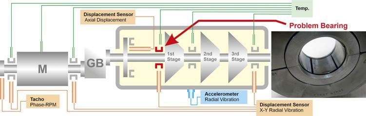
Figure 1. Sensor configuration of the instrument air compressor. There are also a number of imported process parameters from this machine train not shown here (these include suction and discharge pressure and temperature, and motor current). In this case study, the bearing where high vibrations were detected is shown in red. Photo: Fretting on the first stage impeller bearing, presumably caused by a manufacturing defect.
Unusual fault mechanism requires a root cause analysis
The monitoring system successfully detected a fault at an early stage of development while the compressor was still under warranty. The monitoring system in fact played a vital role here since four harmonics were individually monitored. The vibration response of different machine faults manifests itself with different
harmonics, and in this case, it was the third harmonic that gave the earliest indication of a bearing fault. The fault was slow to develop, so long-term trend capability was necessary.
Diagnostic assistance provided by the monitoring system supplier was able to determine that it was a bearing fault. The compressor manufacturer was also contacted, and after disassembly, they determined that fretting on the first stage bearing (Figure 1) was due to poor bonding of the bearing surface as a result of a manufacturing defect. This evaluation is based on the fact that the bearing vibration levels had already started an upward trend not long after commissioning. It is not fully understood why only the third order was excited for this condition.
Further investigation found a scratched bearing surface for the second stage impeller, which was most likely due to a foreign object that entered the bearing during commissioning. Burnt oil on the bearing surface from the third stage impeller was also observed, which was most likely due to carry-over water ingress.
Repair and postrepair results
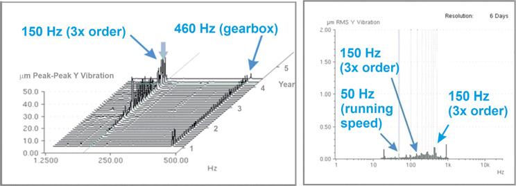
Figure 2. Left: The third order harmonic dominates the vibration response in this spectrum plot (FFT). The 460 Hz signal component from a gearbox pinion remains unchanged, thus precluding the possibility of a fault with this portion of the gearbox (higher frequencies not shown in this plot). Right: After repair, the third order harmonic disappears from the spectrum (constant percentage bandwidth – 6%).
Table 2. Measurements for monitoring air compressor impeller bearings. Because of limited access, an accelerometer is used for monitoring the second stage impeller bearing instead of a displacement sensor
Sensor Measurement name
Relative radial vibration (μm) First and third stage impeller bearings Bandpass
DC – shaft position
Half magnitude – bearing stability Frequency range (Hz) Detection
10 - 5 k RMS & P-P
– RMS & P-P
Relative axial displacement (μm) Thrust bearing First order vector – magnitude and phase –
Second, third, and fourth order – magnitude –
Constant percentage bandwidth (CPB) 16.3 - 1.03 k RMS & P-P
RMS & P-P
RMS
DC (μm) – –
Absolute radial vibration Casing above second stage impeller bearing Bandpass (mm/s2)
Other measurements – same as for displacement sensors except in mm/s 10 - 5 k RMS
The manufacturer replaced all the bearings under warranty and the intercooler drain lines were checked for proper draining of water to avoid carry-over. The inlet air filter was also thoroughly inspected for damage and openings.
After repair, Figure 2 shows a spectrum plot (constant percentage bandwidth measurement of 6% centre frequency) where the third order harmonic for the most part disappears.
Case 2 – detection of improperly assembled gearbox of the propane compressor
The rapid deterioration of an incorrectly mounted spur gear gives little lead time to maintenance. In this case study, early fault detection was achieved by using an automatically calculated alarm trend, but even earlier warning could have been achieved by using other vibration parameters.
Propane compressor train
The propane compressor train in this case study consists of a 75 MW Frame 7 gas turbine driving an axial compressor via a gearbox, as summarised in Table 3. The compressor train is unique in that there is also a variable speed starter motor/generator at one end of the train that is used to help start the gas turbine, which afterwards generates energy to the grid once the gas turbine is operating at speed. Moreover, the single casing centrifugal compressor itself is also complicated in that it processes propane at four different pressure levels to supply refrigeration to the incoming natural gas and pre-cooling of the mixed refrigerant in the LNG liquefaction process.
The gearbox, like the rest of the propane compressor train, is extensively instrumented for protection, condition, and performance monitoring. As shown in Figure 3, X-Y displacement sensor pairs are mounted on each of the bearings of the gearbox.
Observations and analysis
On 15 February, the following condition monitoring measurement indicated a developing fault on the propane compressor gearbox: constant percentage bandwidth filtered spectrum (CPB).
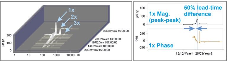
It was the running speed portion of the CPB measurement (Figure 4) that generated an alert alarm using the alarm trend function. The alarm trend was set up for a 10-day lead time to the danger alarm (shutdown). The CPB indicated a pronounced 1× vibration trend as shown on the left of Figure 4.
Although not set to alarm limits, the first order vector measurement data (1× magnitude and phase) was also analysed as a follow up. The 1× vibration magnitude portion of the vector measurement gave a similar lead time before shutdown to that of the CPB measurement, but the phase portion of the measurement started changing even earlier as shown in Figure 4. It would have given over two weeks advance warning. By comparison, the overall vibration measurement (not shown) gave indication of a trend similar to the CPB and vector magnitude measurements since the 1× vibration frequency was directly related to the fault, which was the predominant frequency component in the entire spectrum. But as a protection measurement, the alert limits are set too high for condition monitoring purposes so there is little lead time warning with this measurement.
Table 3. Propane compressor details
Parameter Value
Type Axial
Stages Four
Power 75 MW
Flow capacity 170 000 m3/hr
Highest outlet pressure 30 bar
Lowest outlet temperature -31˚C
Speed 3600 rpm

Post-repair results
When the gearbox was disassembled, the output shaft bull gear was found to be improperly mounted on its bearings. It was this fault that caused a running speed vibration amplitude increase and phase change. When the gearbox was repaired and reinstalled, the vector amplitude vibration went down and the phase stabilised.
Although the 1× vibration measurements detected the developing fault with advance warning, it was the first order phase measurement that could have provided the earliest detection capability and thereby the longest lead time to service, if it was used. Regardless of which measurement is monitored, a rapidly developing fault can be quickly detected before the alert alarm limits are exceeded by using the alarm trend function. Either way, for faults that have a non-linear development, such as an improperly mounted gear, the CPB and vector measurements can detect these faults with sufficient lead time to plan the necessary maintenance.
Conclusion
Figure 3. Sensor configuration for the propane compressor gearbox.
Quality issues or incorrect assembly faults of machine components can complicate fault detection and/or diagnostics, so comprehensive condition monitoring functionality is a must for critical machines. Moreover, outside expertise services can be useful as well for difficult diagnostics. For fast developing faults, maximum lead time warning is crucial for cost-effective maintenance planning, therefore in addition to specialised diagnostic condition Figure 4. Left: The CPB showing the running speed vibration increasing up until shutdown. The monitoring techniques, 2× and 3× orders of the running speed are also shown. Right: The first order phase is visible when automatic alarm trend the vibration amplitude is high enough, as shown in this long-term trend. Around 10 February the functionality is also phase begins to change significantly. The first start until after 15 February. order vibration magnitude upward trend did not important for early fault detection.