8 minute read
Take a look at the tank


Chris Magruder, Olympus, USA,describes the recent advances in phased array inspection for LNG tank fabrication.

The increase in LNG storage and processing projects worldwide combined with the success of portable phased array inspection systems for this application have created a demand in the market for dedicated phased arraybased LNG tank solutions. Radiography testing (RT), a common non-destructive testing (NDT) method used for LNG welds, is time-consuming and causes inspection bottlenecks when it cannot keep pace with production. Using specialised phased array probe sets and software designed for American Petroleum Institute (API) compliance of LNG tank inspection as a


replacement for RT can provide significant improvements in productivity and inspection results.
LNG tank construction
LNG requires cryogenic storage conditions at temperatures below -162˚C (-260˚F). 9% nickel steel alloy tank shells are welded with an Inconel alloy I625 electrode, creating a dissimilar metal weld that remains ductile at cryogenic temperatures to prevent cracking.
LNG tanks are thermally insulated and require a cooling system. They are made up of an inner welded shell to contain the LNG, an outer shell made of concrete, and a thick layer of thermal insulation between the two, requiring that the phased array weld inspections be performed from inside of the tank during construction.
Tank shell sections can be up to 12 m (39 ft) by 4 m (13 ft) in size and beveled for either horizontal welds of different thickness or vertical welds of the same thickness. The largest of LNG tanks under construction today can be up to 45 mm (1.7 in.) thick at the base and include more than 2000 linear m (over 6500 ft) of weld.
NDT inspection of welds during LNG tank fabrication does not necessarily need to synchronise with the completion of each shell ring, meaning the phased array inspection can be staggered or undertaken in stages.
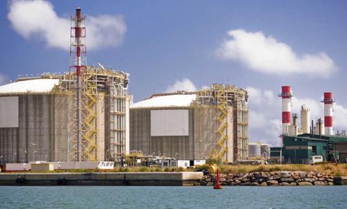
Figure 1. Thousands of meters of welds need to be validated using non-destructive testing (NDT) during LNG tank fabrication.
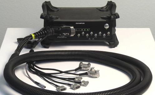
Figure 2. Phased array instrumentation configuration for LNG tank inspection.
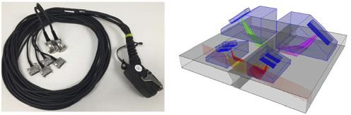
Figure 3. Left: Probe hardware. Right: The scan plan in the acquisition software showing the probe positioning and coverage.
Phased array inspection equipment
To perform an efficient and effective phased array weld inspection of LNG tanks, the recommended equipment consists of an acquisition unit, an acquisition software on a laptop computer, an encoded mechanical or automated scanner, and unique Olympus LNG quad probe that provides full volumetric inspection of the austenitic I625 weld bevel and heat-affected zone (HAZ).
The LNG quad probe is designed for API and ASME compliance and is made of two 1D linear phased array probes and two Dual Linear Array™ (DLA) probes all wired to a single connector for reduced cost and ease of use. The 1D linear phased array probes, typically applied to carbon steel inspections, are used with shear wave wedges to detect and size any bevel and HAZ flaws with precision, but only the DLA probes can reliably penetrate the austenitic I625 weld volume.
Phased array instrumentation designed for a mobile job site is lightweight, ruggedised, water resistant, and can be used on battery or external power in close proximity to the scanner, eliminating the need for long and expensive umbilical probe and scanner cabling. For the LNG quad probe support, a minimum instrument pulser configuration of 32:128 is required.
A laptop is connected to the acquisition unit by Ethernet cable, and the acquisition software includes tools for creating configurations, performing daily calibrations, and managing the acquisition, analysis, and reporting. The LNG inspection workflow is predefined in the software, including the bevel change outs, so the inspection crew can focus on performing the inspection and not on the set-up.
The mechanical scanner used for the data acquisition is selected based on job site conditions. Where a basket lift or scaffolding is available for welding, the inspection crew can use a magnetic, non-motorised scanner and move it along the weld line. More commonly, a motorised scanner with remote controller is used, which can be driven on the weld line with or without a remote camera installed. The 9% nickel shells are sufficiently ferrous for the magnetic wheels of the scanner to stick to the tank.
Testing preparation
Surface preparation of the LNG tank weld requires light buffing to remove weld spatter, and the weld crowns are ground flush at the shell intersections to allow the scanner to pass unobstructed. A phased array system’s data acquisition rate for LNG weld inspection is approximately 75 mm (3 in.)/sec., depending on thickness, and a typical
work shift can include inspection and analysis of several days of welding.
The phased array probes are coupled to the tank’s inner surface with water from either a manual sprayer or electric water pump using approximately 1 l per 5 m of weld, and light water spillage is normally not a problem inside the LNG tank during construction. The scanner technician positions and drives the scanner, keeping it aligned with the weld line, while the inspector watches the data displays in real-time. Defects, when necessary, are marked for repair immediately after the inspection and prior to moving to the next weld.
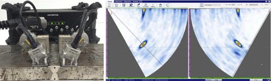
Figure 4. Calibrating the probes using a standard with manufactured flaws in the bevel and weld volume.
Phased array set-up and configuration
The phased array scan plan is the summary of the inspection strategy and includes probe and wedge models, offset positions, angles used for inspections, focus depths, virtual probe apertures, etc., and is documented in the company work procedure and acquisition software in accordance with (IAW) the API 620 and ASME V referencing codes.
All weld bevel designs for the tank are created in the system software in advance, and a scan plan based on thickness for each range of tank shells is prepared. The acquisition software is designed for a fast and efficient workflow, taking approximately 15 min. for the start of shift set-up and calibration or midshift bevel and thickness changeout. Phased array probe calibration The inspection scanning sensitivity is set prior to each series of inspections using welded mock-ups of the shell sections with reflectors fabricated at the bevel fusion for the shear wave probes and in the weld volume for the DLA probes. Movement of the scanner on the mock-up weld validates all aspects of the inspection system, including ultrasonic sensitivity, probe position relative to weld bevel, probe coupling, mechanical encoding, and the acquisition software. API 620 acceptance criteria The I625 dissimilar metal weld used in the fabrication of API LNG tanks differs from carbon steel welds in that the I625 weld volume cannot be penetrated ultrasonically without use of DLA probes.
DLA probes have long been used for inspections of stainless steel and other coarse-grained austenitic materials, and they penetrate the weld using a refracted angle pitch-catch technique. The shear wave probes provide the coverage of the HAZ adjacent to the weld and precision measurements on the bevel flaws. Use of the four phased array probes in this configuration eliminates the need for time-consuming manual flaw prove-up after detection and provides optimum detection and repeatability for LNG weld inspection.
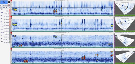
The phased array inspection data is analysed in C-scan top view and S-scan side view data displays that visualise weld flaws and imperfections so they can be characterised, precision sized, and located in the weld for repair. Rescans
Figure 5. Software user interface for data collection and analysis. of repaired areas are performed using the same inspection method as the original weld. The weld acceptance decision is made using API 620 table U1 or table U2 for AUT in lieu of radiography. Both tables require the flaw to be characterised as surface connected or embedded and sized in length and height for an acceptance decision based on weld thickness. Table U2 is most frequently used as it is less sensitive, resulting in a lower reject rate, and can only be applied when certain toughness criteria of the shell material are met.
Personnel and certification Personnel performing phased array inspections of LNG tanks must comply with a company work procedure written IAW qualification and certification of non-destructive personnel testing standards, such as ISO 9712, SNT-TC-A1, or similar. Certification includes training hours, written testing, and proficiency testing performed on artificially flawed and real production weld specimens. The typical two-person crew includes a certified inspector and a scanner technician who is an inspector in training. API and ASME compliance require that the weld quality inspection data and examination reports be approved by a Level III reviewer, which is typically carried out remotely off-site after files are uploaded to a server or cloud at the end of each shift.
Conclusions Implementing phased array inspection systems in replacement of radiography testing in API 620 LNG tank construction is no longer an expensive or risky development proposition. Service companies or fabricators can bid on LNG tank inspection contracts with confidence, knowing dedicated phased array probe solutions are available. Moreover, specialised equipment and fully developed inspection procedures provide a short training track for LNG inspection project success.