12 minute read
A coating shield


Richard Holliday, PPG Protective and Marine Coatings, UK, outlines a detailed test undertaken to compare epoxy passive fire protection products commonly specified for the protection of steel structures.


The hydrocarbon processing industry has strict international testing standards related to the performance of passive fire protection (PFP) coatings for oil and gas platforms, terminals, refineries, and other petrochemical facilities.
In recent years, several high-profile PFP coatings failures in cold-weather climates, such as a well-documented case at the oilsands in Alberta, Canada, have demonstrated the need for more rigorous testing of intumescent epoxy coatings for application in such environments.
Whether floating offshore or based on land, LNG installations are essentially densely populated factories in which fire hazards are in close proximity to process areas as well as facilities such as control rooms and even accommodation modules. This increases the risk of rapid escalation combined with the need for specialist escape and evacuation provisions for personnel while trying to minimise damage to the asset.
Growing interest in offshore floating LNG (FLNG) for export trade and increasing numbers of import facilities for local power supply mean that the number of offshore fixed and FLNG installations is growing. Such projects may often feature gas storage close to industrial installations or at ports where a nearby population or critical infrastructure is present.
Fire ratings for such installations are traditionally based on the ability to withstand pool fires, which may not be sufficient


where products are stored and handled under cryogenic temperatures and at high pressure. LNG presents fire risks before or after liquefaction, most dangerously the risk of jet fire.
Regulators such as FERC in the US expect project designers to demonstrate that hazards such as jet fire and cryogenic spills are adequately addressed in their permit applications, but the obligation is on safety engineers to manage risk to acceptable levels rather than meet a regulatory standard.
Safety case requirements compel engineers to identify the unique hazards of their facility and ensure safety and environmental critical elements such as firewalls and critical structural and process components are provided with adequate protection, but these are only required to meet performance standards drawn from industry guidelines in providing resistance to credible threats.
To resist jet fires more effectively requires not just highperformance coatings but a testing regime that includes the specific characteristics of highly flammable and high-pressure inventories, often in extreme environments.
This article highlights a comprehensive test regimen sponsored by a major coatings manufacturer and developed and executed by a leading international university, which compared five intumescent epoxy passive fire protection (EPFP) products commonly specified for protection of steel structures in the hydrocarbon processing industry.
The testing served not only to quantify the potential performance of the five EPFP coatings in less-temperate climates but may also provide a template for industry-wide adoption of more comprehensive testing standards for PFP coatings in general, particularly as their use continues to expand in northern locales and on lighter, pre-coated, modular steel structures.
When evaluating PFP coatings for any application, it is important for specifiers to look beyond the fire rating. This is true for all PFP coatings types, but especially so for intumescent EPFPs, which are increasingly preferred over traditional cement-based and fibre-based PFP materials due to their lightness, flexibility, performance, and ease of application.
While any PFP material will have fire certification, EPFP intumescent epoxy coatings should be selected for their ability to meet all the demands associated with their end use, including their ability to survive transportation to a job site, as well as the installation and construction methods employed at the job site, without cracking or delamination. Such systems are expected to be virtually maintenance free for the life of the facility and ready to perform the required fire protection function at any point in its design life – one particularly hard winter should not risk damaging the EPFP.
With the growing popularity of stick-built and modular off-site construction techniques, steel beams, columns, and other components for LNG facilities are increasingly prefabricated and finished with EPFP coatings before they are delivered to the job site. In many cases, these fireproofed components are shipped across oceans and continents, through changing weather conditions. This, in turn, can cause poorly designed coatings to crack or delaminate and compromise their performance before they are ever placed into service.
This trend, combined with the increasing prevalence of gas import or export projects being constructed in extremely cold environments, makes expanding the scope of industry standard testing of PFP coatings beyond their existing parameters more critical than ever.
Table 1. Tests performed
Material Temperature (˚C)
P 25, 5, -10, -30, -50
N 25, 15, 5, -10, -30, -50
C1 25, 15, 5, -10, -30, -40, -50
C2 25, 15, 5, -10, -30, -40, -50
C3 25, 15, 5, -10, -30, -50
Extra tests were performed on products C1 and C2 to establish the failure point because these samples did not provide a conclusive outcome at -50°C.

Figure 1. A test methodology was developed to quantify the performance of the new coating against four alternatives.
Specifying PFP coatings
Due to the many options available, picking the right PFP coating system to meet the specific safety demands of a particular facility or application can be a daunting task. The following guidelines, authored by an industry consultant and published in 2014 by a leading offshore engineering trade journal, outline a step-by-step hierarchy of needs that engineers can reference to determine the safest and most effective PFP coating system for their facilities. According to these guidelines, the ideal PFP coating system designed for a facility: Shall not generate hazards, such as the formation of corrosion which can lead to leaks and loss of integrity, or use hazardous materials such as asbestos.
Shall not degrade with time in the environment to which it is exposed during its designed service life, or before the first maintenance, including process operating conditions. Shall survive an initial explosion, including resultant overpressure, drag force, deformation of substrates, and impact from flying debris. Shall survive an initial high heat flux, high-momentum jet fire that may occur. Shall provide fire protection for the required time and maintain the temperature of the item being protected below its critical temperature.
Over the years, many intumescent coating types have been formulated to achieve these demands on steel structures in traditional temperate and tropical environments. However, due
to their rigid formulation, some of these products have proved not to be well-suited for colder climates where thermal cycling extremes can cause steelwork to expand and contract dimensionally and frequently, which can lead to delamination, cracking, and loss of fire integrity.
A new testing regimen
In 2018, a major coatings manufacturer developed a new epoxy-based EPFP coating that was designed to be thinner, lighter, and more flexible than alternate PFP coatings, yet offer the same high levels of impact, jet fire, and pool-fire resistance as other field-proven counterparts.
To investigate the viability of its new formulation, the company engaged independent researchers at a leading international university who are recognised industry experts in the fields of structural dynamics and PFP material science.
Together, they developed a test methodology to quantify the mechanical performance of the new coating against one of the sponsoring manufacturer’s existing and well-proven EPFP coatings and together with three commonly specified alternative EPFP coatings. The five materials referenced earlier are identified as follows: Product P – Serving as the benchmark material, this product has a proven 35-year track record of cracking resistance in extreme and cold environments. It was developed by the sponsoring manufacturer and is wellregarded throughout the industry. Product N – The next-generation flexible and extremely lightweight epoxy intumescent coating. It was engineered by the sponsoring manufacturer to accommodate weather extremes and the lighter steel structures now being constructed for many hydrocarbon applications. Product C1 – A rigid epoxy-based PFP coating with a 15-year track record developed for the onshore UL 1709 fire test standard market.
Product C2 – A relatively rigid, mesh-free
EPFP coating that had previously exhibited failure in cold climates on structures built using modular and stick construction techniques. Product C3 – A newly launched, novel epoxy-based EPFP intumescent coating described as a ‘low-temperature-cure modified epoxy with a more rigid network.’
The test regimen was conducted as follows.
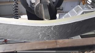
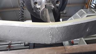
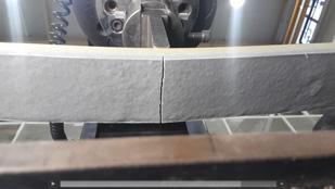
Figure 2. Exhibiting ductile tearing at room temperature. Left: product P; right: product N.
Figure 3. Product N ductile-brittle transition <0˚C (32˚F) temperature.
Figure 4. Exhibiting brittle failure at room temperature. Left: product C3; right: product C1.
Test specimens
The five EPFP coatings described were applied to flat steel bars measuring 600 mm long, 50 mm wide, and 10 mm coated at a nominal thickness of 8 mm.
Flat bars were selected because they were consistently coated by draw-down technique using a shuttering frame. The dimensions were large enough that the effect of stresses induced by differentials in coefficients of thermal expansion could be easily and consistently measured. The bars were also small enough to fit in a freezer with temperatures as low as -60˚C (-76˚F). 15 specimens were prepared for each of the five EPFP materials, equalling 75 specimens in total.
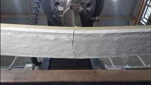
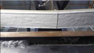
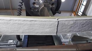
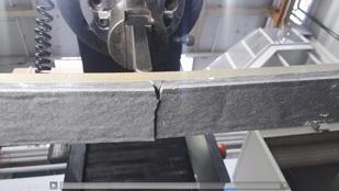
Figure 5. Left: product C1 exhibiting delamination at 0˚C (32˚F). Right: product C2 exhibiting delamination at room temperature.
Test arrangements
A three-point bend test was employed on each steel bar with the specimen supported on two brackets. Total specimen length, as detailed above, was 600 mm. There was a clear span of 500 mm between the supports with the EPFP coating occupying 460 mm of the clear 500 mm span.
Using a 200 kN capacity Instron, the maximum vertical displacement of each
specimen was measured at mid-span by the movement of the loading platen built into the test instrument.
Test calibration Key observations
A calibration test of an uncoated specimen at an ambient temperature of 25˚C (77˚F) was undertaken to establish a benchmark load displacement-surface strain relationship.
Temperature calibration
A calibration test of coated EPFP specimens was completed to establish a common through-thickness temperature profile. This was undertaken by cooling a selection of specimens to -50˚C (-58˚F) for 24 hours, then inserting a needle thermocouple into the midpoint of the EPFP.
This temperature was then compared against the surface temperature of the steel and the EPFP coating using an infrared gun thermometer, which showed that the temperatures were consistent throughout the thickness of the coating. Changes in temperature of approximately 5.5˚C (10˚F) were noted to occur after being outside the freezer for 1 min., and 10˚C (18˚F) after 2 min. outside the freezer.
Main test
75 tests were performed, consisting of the combinations of specimen type and temperature shown in Table 1. For each test, all specimens were held at specified temperatures for 24 hours before being subject to strain-temperature testing.
During the tests, visual observations were made of the first sight of the following: First surface cracking or tearing. First through-thickness (down-to-steel) cracking. Delamination or disbonding.
Figure 2 shows that the flexible products are able to withstand large deflections before the onset of surface tearing. Figure 3 shows that below 0˚C (32˚F) the tearing transitions into a cracking but the product remains adhered to substrate.
Figure 4 shows the more rigid products, C1 and C3, already exhibit cracking at room temperature, and at below 0˚C (32˚F) the failure mode exhibits delamination from the substrate as shown in Figure 5. Figure 5 also shows that product C2, the most rigid material, exhibits delamination from the substrate even at room temperature.
The points of displacement at which the observations were made were recorded, then converted to surface strains using a calibration curve created from the calibration tests described earlier. A minimum of two specimens of each material were tested at each temperature specified in Table 1. As expected, the three rigid intumescent EPFP coatings (products C1, C2, and C3) performed the least well, exhibiting brittle failure modes at relatively low strain levels and, in some cases, delaminating extensively from the steel test specimens even before the application of load at low temperatures.
Product P, the benchmark EPFP coating with the 35-year track record, performed the best at low temperatures, exceeding the yield-point strain limit of 0.2% for steel structures at temperatures of -50˚C (-58˚F.)
Product N, although slightly less flexible than product P, also performed very well at low temperatures, again exceeding the industry standard strain limit of 0.2% at a temperature of -50˚C (-58˚F).
Conclusions
Until recently, the oil and gas industry has operated under the belief that, when it comes to EPFP coatings ‘harder is tougher.’ But with the prevalence of modular construction and its demands for lighter steel components – as well as the increasing level of industry construction in cold weather climates – that truism no longer applies.
It is now essential that designers understand how steel behaves in various conditions and why it can require more flexible PFP coatings. Just as PFP coatings must be formulated to accommodate these new realities, the scope of industry-standard testing must expand to meet them as well.
The design of safe, affordable, and effective EPFP coating systems, tailored to the specific requirements of the facility it is meant to serve, can be a complex undertaking. The development of new EPFP coatings solutions to meet the changing demands of the industry has the potential to complicate matters further. For all these reasons, the need for more robust testing standards and protocols for the next generation of EPFP coatings, including cold-weather testing, is more critical than ever.
Test results
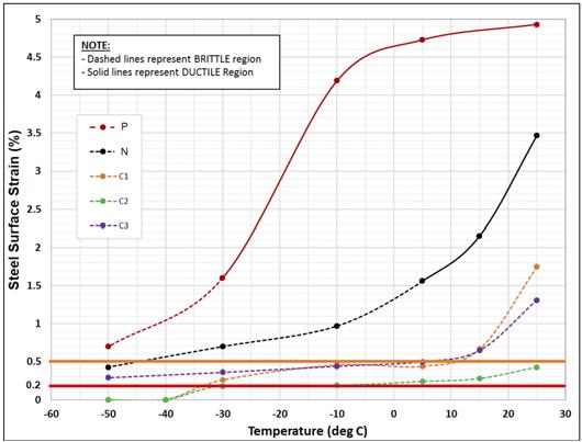
A summary of test results for all specimens was recorded and failure-strain results for each product were plotted to illustrate their trends of transition between ductile (tearing) and brittle (cracking) failure as well as to establish if the products exhibited delamination.
This is shown in Figure 6 which plots the steel surface strain where the product tears or cracks the EPFP coating against key temperatures of interest.
As the graph illustrates, there is a direct correlation between temperature and load failure with two of the products remaining undamaged at strains greater that 0.5% across the critical temperature range.
Figure 6. Strain-temperature plots at first crack for tested epoxy passive fire protection (EPFP) materials.