
CONTENT
Intelligent Force Printing – Hybrid Authorship and Network Contributors In Architectural Design
Toward a Collaborative Robotic Platform: FUROBOT
Intelligent Force Printing Topology Optimization In Architectural Design
Progressive Spatial Structural Morphology by Designing the Force Geometry
FOREWORD
In the ever-evolving field of architectural design, the exploration of new technologies and innovative approaches has become essential to push the boundaries of what is possible. The studio led by Professor Philip Yuan and Dr. Nic Bao at RMIT Architecture, described in this book, represents a significant step forward in this pursuit, focusing on the potential application of integration of computational design and robotic 3D printing. It is within this landscape of exploration that the concept of Intelligent Force Printing emerges as an extraordinary fusion of technology, design, and structural ingenuity.
Intelligent Force Printing is a captivating book that unveils the remarkable journey of a design studio dedicated to harnessing the transformative power of 3D robotic concrete printing. Here, we embark on an odyssey into the realm of architectural possibilities, where the traditional approaches to construction are reimagined, and the hands of visionary architects shape the future of the building.
In this research-based design studio, the focus lies on the potential application of 3D robotic concrete printing as structural components through an intelligent computational design process. The students, guided by a passionate teaching and support team, immerse themselves in the exploration of advanced additive manufacturing techniques, specifically the large-scale concrete 3D printing technique. Their collective aim is to revolutionize the construction industry by addressing the significant scientific challenge of achieving a printing process that yields structurally robust objects.
Within the chapters of this book, you will witness the culmination of their efforts which are a convergence of artistry, technical prowess, and ground-breaking research. Their exploration revolves around a structural performative-based design strategy, interwoven seamlessly with the integration of robotic fabrication techniques. With tools such as compression-only form-finding, structural topology optimization, and the prowess of robotic arms, they chart a path towards architectural excellence.
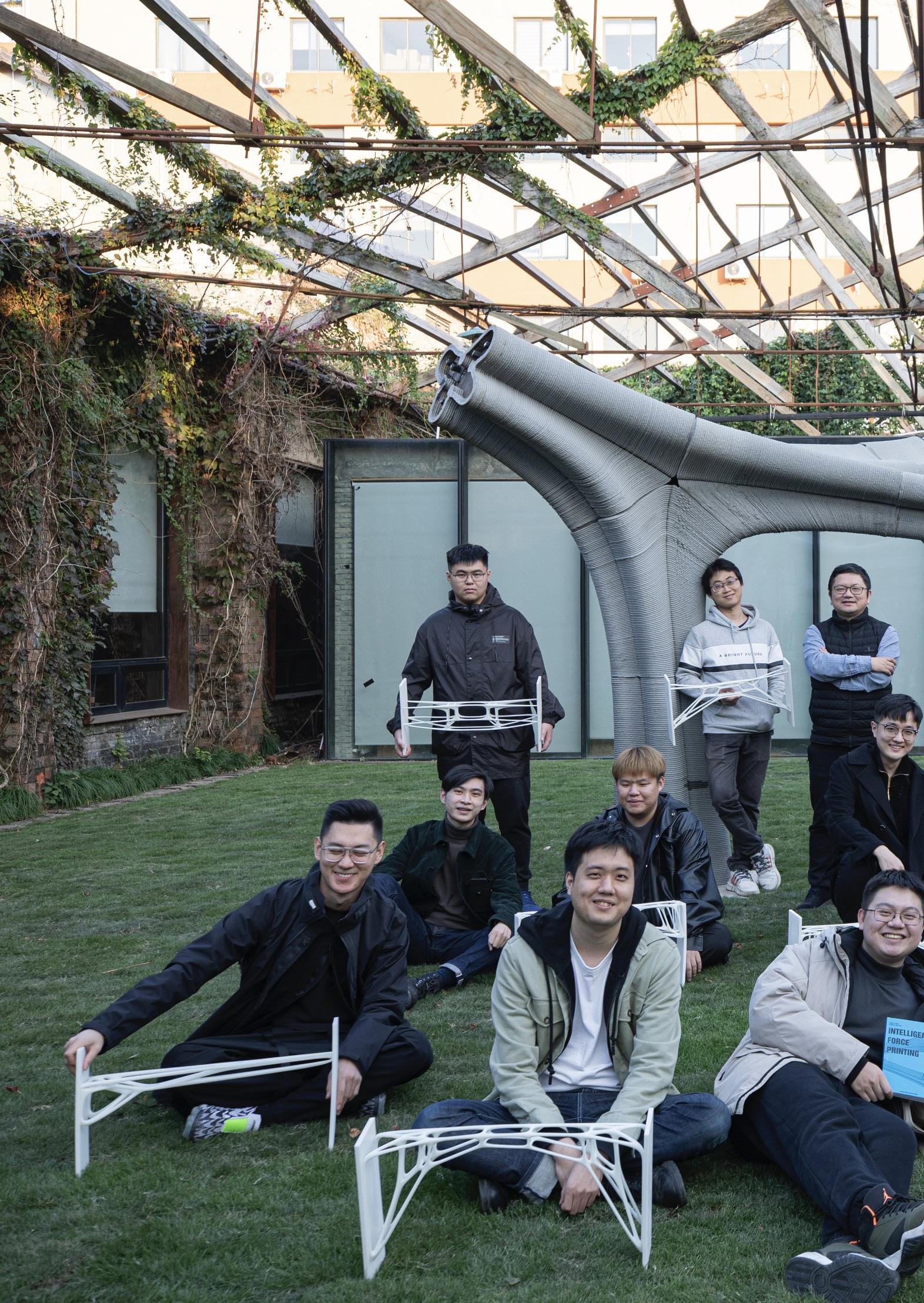
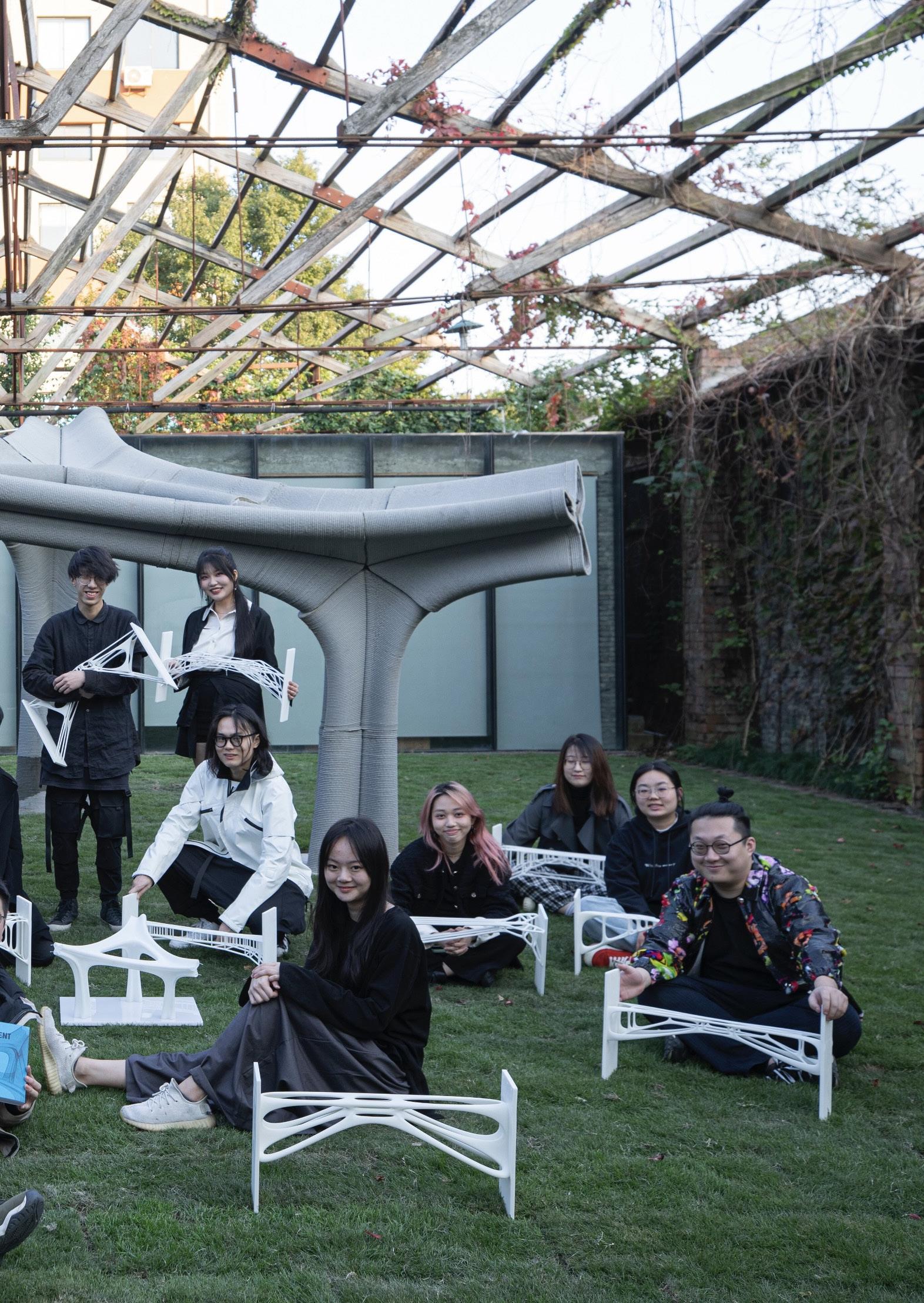
At the heart of this journey lies a stunning, experimental large-scale pavilion; an awe-inspiring installation that serves as the embodiment of the emerging design philosophy and a testament to the potential application of future 3D articulate printing technology in the construction industry.
But this book extends beyond the pavilion’s physical manifestation. It serves as a catalyst for critical engagement, urging students to reflect on the value of these techniques and their potential applications beyond the pavilion’s scale. It invites them to ponder how these innovative approaches can be harnessed in diverse contexts, igniting a spark of creativity that transcends boundaries and challenges the norms of the architectural convention.
The studio outline — meticulously crafted — serves as a guiding light, nurturing students’ understanding of tectonics and technique. By immersing themselves in this immersive educational environment, the students acquire an in-depth knowledge of computational tools and gain invaluable insights into the ever-evolving landscape of architectural development. Their hands-on involvement in actual construction experiments adds a layer of practicality to their theoretical explorations. The final review has been moderated by esteemed professionals and scholars, including Prof. Vivian Mitsogianni, Prof. Jane Burry, Prof. Roland Snooks, Prof. Patrick Schumacher, Dr. Shajay Bhooshan, Klaas De Rycke, and myself.
As you embark on this literary journey, prepare to be captivated by the beauty of form and the synergy of design and technology. Each page unveils the harmonious collaboration between the human mind and the robotic arm — where creativity is boundless and innovation is the driving force. You will witness the meticulous dance of intelligence and force, resulting in architectural marvels that push the boundaries of what was once thought achievable.
Intelligent Force Printing is not only a testament to the studio’s achievements but also an invitation to reflect, dream, and imagine. It beckons the reader to contemplate the profound impact of these cutting-edge technologies, not only within the context of a single pavilion but in a broader architectural landscape. It sparks curiosity, ignites passion, and invites readers to envision a future where Intelligent Force Printing revolutionizes the way we design, construct, and inhabit our built environment.
As you navigate through these pages, may you be inspired to explore uncharted territories, challenge conventional norms, and pioneer new frontiers of architectural excellence. Together, let us explore a journey that defies limitations, where the synergy of intelligence and force propels us towards a future of architectural innovation.
Distinguished Professor Mike Xie RMIT University
This is a book about pushing boundaries – notably about innovating though new applications of technology. The studio led by Visiting Professor Philip Yuan and Senior Lecturer Dr Nic Bao at RMIT Architecture, described in the book, focuses on the integration of computational design and robotic 3D printing. This is a critical trajectory in designing for a more streamlined, advancedmanufacturing-informed future construction industry. It is within this landscape of exploration that the novel concept of Intelligent Force Printing emerges as a fusion of technology, design, and structural ingenuity.
Intelligent Force Printing is a captivating book that unveils the remarkable journey of a design studio dedicated to harnessing the transformative power of 3D robotic concrete printing. Here, we embark on an odyssey into the realm of architectural possibilities, where the traditional approaches to construction are reimagined, and the hands of visionary architects shape the future of the building.
In this research-based design studio, the focus lies on the potential application of 3D robotic concrete printing of structural components through an intelligent computational design process. The students, guided by a passionate teaching and support team, immerse themselves in the exploration of advanced additive manufacturing techniques, specifically large-scale concrete 3D printing techniques. Their collective aim is to revolutionize the construction industry by addressing the significant scientific challenge of achieving a printing process that yields structurally robust objects.
Within the chapters of this book, you will witness the culmination of their efforts, a convergence of artistry, technical prowess, and significant original research. Their exploration revolves around structural performance and design strategy, interwoven seamlessly with the integration of robotic fabrication techniques. With tools such as compression-only form-finding, structural topology optimization, and the programming and application of robotic arms, they chart their path towards originality and excellence.
Their journey’s end is an experimental large-scale pavilion, a spectacular installation that serves as the embodiment of the emerging design philosophy and as a testament to the potential application of future 3D articulate printing technology in the construction industry.
But this book extends beyond the pavilion’s physical manifestation. It serves as a catalyst for critical engagement, urging students to reflect on the value of these techniques and their potential applications beyond the pavilion’s scale. It invites them to ponder how these innovative approaches can be harnessed in diverse contexts, igniting a spark of creativity that transcends boundaries and challenges the norms of the architectural convention.
The studio outline, meticulously crafted, serves as a beacon, nurturing students’ understanding of tectonics and technique. By immersing themselves in this immersive educational environment, the students acquire an in-depth knowledge of computational tools and gain invaluable insights into the ever-evolving landscape of architectural development. Their hands-on involvement in actual construction experiments adds a layer of practicality to their theoretical explorations. The final review has been moderated by esteemed professionals and scholars, including Professor Vivian Mitsogianni, Dean of AUD at RMIT; Distinguished Professor Mike Xie, Director of CISM at RMIT; Professor Roland Snooks, Director of Tectonic Formation Lab at RMIT; Professor Patrick Schumacher, Director of ZHA; Dr. Shajay Bhooshan, Founder of ZHA CODE group; Mr Klaas De Rycke, Director of Bollinger Grohmann; and myself.
As you embark on this literary journey, prepare to be captivated by the beauty of form and the synergy of design and technology. Each page unveils the collaboration between the human mind and the robotic arm, where creativity is boundless, and where challenge and innovation are the driving forces. You will witness the meticulous dance of intelligence and force, resulting in architectural outcomes that push the boundaries of what was once thought achievable.
Intelligent Force Printing is not only a testament to the studio's achievements but also an invitation to reflect, dream, and imagine. It beckons the reader to contemplate the profound impact of these cutting-edge technologies, not only within the context of a single pavilion but in a broader architectural landscape. It sparks curiosity, ignites passion, and invites readers to envision a future where Intelligent Force Printing revolutionizes the way we design, construct, and inhabit our built environment.
Professor Jane Burry Head of School of Architecture and Civil Engineering, The University of Adelaide
INTRODUCTION
This studio explores the potential application of 3D robotic concrete printing as structural components through the intelligent computational design process in the field of architectural design. Advanced additive manufacturing technique, especially the large-scale concrete 3D printing technique, aims to change the construction industry. Nowadays, the significant scientific problem is how to achieve the printing process as a structural object.
This studio will focus on the structural performative-based design strategy and its appropriate integration with robotic fabrication techniques. With tools such as compression-only form-finding, structural topology optimization, and robotic fabrication, the students will participate in a sequence of prototype research, learn intensively about the computational tools to gain knowledge into the topic of architectural development, and participate deeply in the actual construction experiments.
As the studio’s output, one experimental large-scale pavilion (installation) will be finally built and a research-based book will be published. It will explore both the forms with the emerging design philosophy and the possible application of future 3D articulate printing technology in the construction industry.
This studio is part of a group of studios and electives run this semester. A teaching and support team will support the whole process.
The studio outline is very focused on tectonics and technique and we need to let students critically engage with the value of these techniques and reflect on the success of their own particular application of them. It may also be helpful for students to engage with how these techniques could be applied at scales beyond the pavilion. The questions can be addressed by the students individually or in teams after the workshop via a seperate discrete design task exploring how to apply the technique in another context.
Studio Leaders
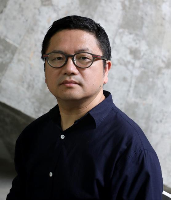
Philip F. Yuan
Professor, College of Architecture and Urban Planning, Tongji University
Philip F. Yuan
Associate Dean, professor of the College of Architecture and Urban Planning (CAUP) at Tongji University.
Yuan is also a Thomas Jefferson professor at University of Virginia (UVA, 2019), a visiting professor at Massachusetts Institute of Technology (MIT, 2019) and at the Royal Melbourne Institute of Technology (RMIT, 2021), and editor-in-chief of Architectural Intelligence journal. Yuan founded DigitalFUTURES Assocation in 2011. He plays a leading role in the frontiers of digital architecture. His research focues on the realm of computational design and robotic fabrication. His works have been collected by MoMa, New York, M+, Hongkong and Centre Pompidou, Paris. He has also participated in the Venice Biennale, Chicago Biennale, Milan Triennial, Russian Biennale, etc.
E-mail: philipyuan007@tongji.edu.cn
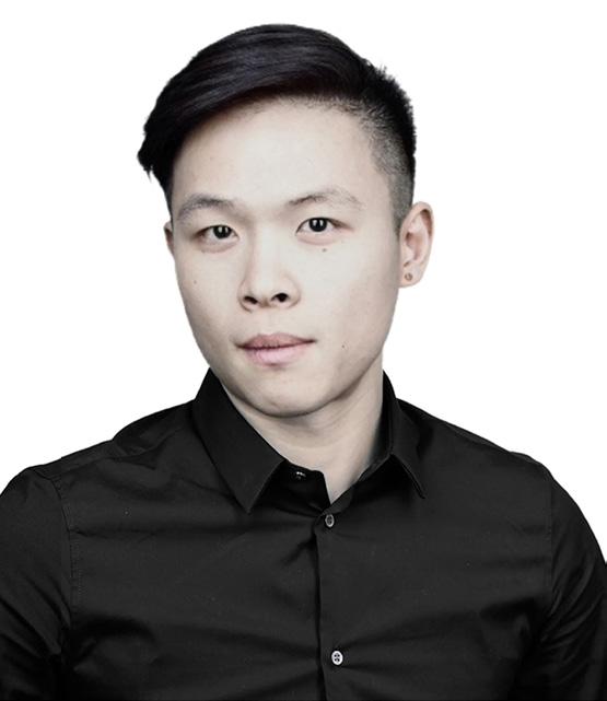
Dingwen ‘Nic’ Bao
Senior lecturer and the Architecture Technology Stream Coordinator at the School of Architecture and Urban Design, RMIT University. Bao’s research focuses on performance architecture, bio-inspired design, computational design, structural optimization, behavioral algorithms, additive manufacturing, robotic fabrication and intelligent construction. Bao has published over 40 articles and serves as an editorial board member of Architectural Intelligence journal and Sustainable Structures journal. Bao is an Australian and U.S. registered architect, and U.K. RIBA chartered architect. Bao is the director of BW Architects (BWA) and Wonderform Studio, founder of FormX and partner at Ameba. Bao’s projects have been exhibited at NGV Melbourne Design Week, Venice Biennale, Shenzhen Biennale, IASS Expo, etc. Bao also received numerous research and design awards, including Young CAADRIA Award, DigitalFUTURES Young Award, MUSE Design Award, Grand Prix Du Design Paris Gold Award, IAI Design Awards, A’Design Award, RMIT Prize for Research Impact (HDR) and RMIT Award for Research Excellence (ECR).
E-mail: nic.bao@rmit.edu.au
Dingwen 'Nic' BAO
Senior Lecturer in Architecture, School of Architecture and Urban Design, RMIT University
Teaching Assistants
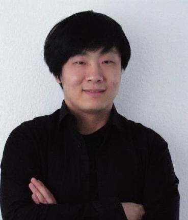
Hao WU
PhD. candidate, CAUP Tongji University
Assistant Professor, CAUP Tongji University
Students





Xinjie ZHOU
PhD. candidate, CAUP Tongji University






Xiang WANG
Bowen LI
Wenjie GAI
Zhengqian PENG
Da WANG
Xinyu WU
Zhuohua TAN
Bowen LI
Yuhan BAO
Ziyan LI
Jingyi LIU
Zengwei WANG
Ziyu ZHOU
Ruoxing WANG
Zhangxizhi WANG
LECTURES


GRAPHIC STATICS IN BRIDGE STRUCTURES
Xiang WANG
Assistant Professor, CAUP Tongji University
POLYFRAME TUTORIAL
Masoud AKBARZADEH
Assistant Professor, Weitzman School of Design, University of Pennsylvania
AMEBA TUTORIAL
Dingwen 'Nic' BAO
Lecturer, School of Architecture and Urban Design, RMIT University
INTRODUCTION OF ROBOTIC OPERATIONS AND THE USING OF FUROBOT
Ming LU
PhD. candidate, CAUP Tongji University
ROBOTIC 3D PRINTING TECHNIQUE AND THE WORK FLOW
Liming ZHANG
PhD. candidate, CAUP Tongji University
RHINO TUTORIAL
Chao YAN
Assistant Professor, CAUP Tongji University
STUDIO CALENDAR
STAGEONE:ComputationalWorkshop (TA:XinjieZHOU)
08.05 Thu [Afternoon] 13:30 p.m. -17:30 p.m., Archi-Union big meeting room
» Lecture by Prof. Philip. F. Yuan (Topic: Workshop Introduction of INTELLIGENT FORCE PRINTING)
» Lecture by Dingwen 'Nic' BAO (Topic: Intelligent Tectonics - Topology Optimization in Architecture)
» Lecture by Xiang WANG (Topic: Structure Form-Finding and Optimization Design)
08.08
[Morning] 09:30 a.m. -12:00 a.m., Archi-Union big meeting room
» Lecture by Yan CHAO (Topic: Rhino)
» Tutorial by TA Hao WU and Xinjie ZHOU on software installation, set up Debug and Python basics, and Mesh/Network construction
[Afternoon] 13:30 p.m. -17:30 p.m., Archi-Union big meeting room
» Lecture by Xiang WANG (Topic: Structural Finite Element Analysis and Optimization (Karamba))
» Tutorial by Hao WU and Xinjie Zhou
08.12 Thu [Afternoon] 13:30 p.m. -17:30 p.m., Archi-Union big meeting room
» Lecture by Dingwen ' Nic' BAO and Xiang WANG (Topic: Structural Topology Optimization (ameba))
» Practice: Each two students design a small scale structural-based prototype model
08.15 Sun [Morning] 09:30 a.m. -12:00 a.m., Archi-Union big meeting room
» Presentation for the small scale structural-based model Design (1)
» Lecture by Dingwen ' Nic' BAO and Xiang WANG (Topic: Structural Topology Optimization case study (Ameba))
STAGETWO:3DRoboticConcretePrinting (TA:HaoWU)
08.15
[Afternoon] 13:30 p.m. -17:30 p.m., Archi-Union big meeting room
» Lectures by Ming LU:
• Robotics: Principles and Industrial Applications
• Basic Introduction of Robotic Operations and Using of FUROBOT
08.19
[Afternoon] 13:30 p.m. -17:30 p.m., Archi-Union big meeting room
» Lecture by Liming ZHANG (Topic: Introduction of the Robotic 3D Printing Technique and the Work Flow)
» Tutorial by TA Hao WU and Xinjie ZHOU on using robotic 3D concrete printing techniques and fabricating a small-scaled model (maybe printing seven blocks with different patterns)
[Morning] 09:30 a.m. -12:00 a.m., Archi-Union big meeting room
» Presentation for the small scale model 3D robotic fabrication (2)
» Tutorial by TA Hao WU and Xinjie ZHOU for design for the final pavilion / installation
[Afternoon] 13:30 p.m. -17:30 p.m., Archi-Union big meeting room
» Lecture by Liming ZHANG (Topic: Introduction of the Robotic 3D Printing Technique and the Work Flow 2)
[Morning] 09:30 a.m. -12:00a.m., Archi-Union factory
» Practice: design for the final pavilion / installation
[Afternoon] 13:30 p.m. -17:30 p.m., Archi-Union big meeting room
» Final Presentation of the single design competition (3)
• Selection of the best idea to be developed in the group design stage
• All Students should prepare the final model of the designed pavilion—it will be 3D printed
» Q&A by TA Hao WU and Xinjie ZHOU for the 3D concrete printing tools
» Practice: Students will be divided into two groups for 3D robotic concrete printing and preparation for the final assembly. All fabrication work should be finished on 06.11.2021
• Design Group: Prepare the technical details for the design, collaborate with the publication team, and prepare the final review
• Fabrication Group: collaborate with the fabrication team to finish all the structural elements
• Recording and publication Team: work with the TA for final presentation and publication
STAGETHREE:FinalPresentation (TA:HaoWU&XinjieZHOU)
[All day] 09:30 a.m. -17:30 p.m., Archi-Union courtyard
» Final assembly of the 3D robotic concrete printing pavilion
09:30 a.m. -12:00 a.m., Archi-Union big meeting room
» Prepare the final materials for presentation
[Afternoon] 13:30 p.m. -17:30 p.m., Archi-Union big meeting room
» Final group public presentation (4)
concepts of architects and machines can be understood by both sides simultaneously architects and machines learn and evolve from each other in dialogue, and the relationship between man and machine is so close that only mutual persuasion and compromise can lead to a certain level of agreement and perception.[14] In the symbiosis of man and machine, the machine is not a tool that man can decide unilaterally.
This conception of symbiosis is similar to the concept of “Cyborg” proposed by Andy Clark and related to the style of many hands proposed by Mario Carpo.[15,16]
Mario Carpo’s style of many hands points to an iterative group participation activity, a state of perpetual iteration that is the meaning of the existence of digital objects. Mario Carpo leads this concept to Deleuze’s discussion of “Objectile”.[16]
Andy Clark argues that humans themselves are innately Cyborg, capable of forming a deep human-technological symbiosis with tools—a thinking and reasoning system whose mind and self are scattered across biological brains and non-biological circuits,[15] and in Clark’s eyes—in a Cyborg system—the boundary between tools and people is blurred. He divided tools into transparent and opaque tools based on tool characteristics. A person uses transparent tools as if they were his own hands; in contrast, opaque constantly emphasize the boundaries between tools and people.[15] Under this theory, transparent and opaque tools are interchangeable, and when a person knows some tools well through learning, these tools become transparent tools and the person constitutes a Cyborg system with the tools. This Cyborg system is, therefore, a dynamic and changing system, yet still anthropocentric. Both transparent and opaque tools are defined from human perspective and are dependent on humans themselves.
In contrast to the Cyborg concept, Deleuze’s “Becoming-machine” has no such anthropocentric tendency. Slavoj Zizek points out that the connotation of "Becoming-machine" is not how machines imitate the human brain, but how the nature of human thought is dependent on external mechanical complements, and that what matters in this definition is the particular way in which an object or machine is assembled with other objects or machines.[17] According to Manual Delanda’s ideas about new materialism,[3] the properties possessed by material materials themselves can also participate in this composite relationship. Thus, in designing architecture with digital tools, it is meaningless to discuss only the tools themselves and to discuss only the people. Attributing creativity to either party detaches the tools or the people from the community they constitute. In this community, not only the relationship between people and tools is included, but also the relationship between people and people and between tools and tools. This complex system will iterate as people change and tools change, and what will eventually form will be a dynamically changing hybrid authorship.
Unlike the “collage” paradigm proposed by Wiscombe, the design outcome of such a hybrid community would not be a collage or segmented but relatively unified and integrated.[18] This integration and unification would result from ambiguity, making it impossible for any individual separated from the hybrid community to claim authorship. An individual isolated from a diverse community cannot claim authorship, which is only proven when they form a whole. As Antoine Picon puts it, architecture is more than ever a collaborative practice with stratified and networked contributions, from designing software to contributing to particular parts of architecture.[19] At this level, the so-called authorship of generic objects versus the authorship of the final product no longer applies.
What this hybrid authorship suggests is a new design process between humans and tools that may be neither linear nor cyclic iterative, but a more complex interaction that depends on the state of the human-to-tool hybrid at the time. Yet it is predictable that, with various AI technologies still evolving, humans will continue to play a dominant role in this system until some time in the future.
Figure 2 Design thinking and construction methods
Figure 1
authorship
all stages. Digitalization has almost entirely updated the methods and approaches of traditional architectural design, and it has also had a profound impact on the construction process. The internal operational process of FUROBOT can be simplified as shown in Figure 5. This operational process represents the logic of the software and is a crucial concept that needs to be clearly understood during the software's usage.
(1) Obtaining the final TCP
To cater to various working scenarios, FUROBOT offers the option of automatically rotating TCP. Generally, the initial pose state is critical to the robot's movement, and FUROBOT employs angle instructions to accomplish this task. For the sake of attitude selection and inverse solution in robot kinematics, incorporating a PlaneToPlane (PTP) command prior to executing any straight-line command can ensure smooth movement. Users have the option to manually insert a PTP instruction, whereby FUROBOT will append it to the head of all LIN command groups automatically. Changes in the mobile robot's position and rotation can be achieved by external axes and root device. Within the FUROBOT logic, it is necessary to choose only one between the external axis and the root coordinate; if both are entered simultaneously, only the external axis will operate.
(2) Simulation and offline programs
The response speed of the software plays a critical role in simulating a large number of target points. FUROBOT employs an improved dichotomy and region search algorithm, which enables the robot to promptly locate the corresponding target plane. Furthermore, transition simulations between each target plane are taken into account. The quaternion SLERP method is utilized for trajectory interpolation, thereby ensuring smooth simulation. Notably, different brands of robots use distinct proprietary programming languages to generate offline files. In addition to merely replacing the
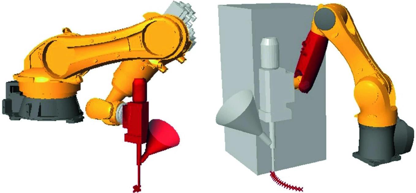
Figure 6
Two kind of collision

same command with different robot languages, variations in grammatical structures also exist. To address this issue, the user needs to provide the file storage path, and FUROBOT will automatically output the offline program file with the appropriate extension according to the input robot type.
(3) Checking
To ensure the safe operation of a robot, inspection is crucial. The inspection process includes the following items: Collision detection: This is the most critical aspect of ensuring safe construction. Collision detection is divided into two types, collision between robotic arms and external objects and collision between robotic bodies and tools (Figure 6) Workspace access and limit: This item involves checking whether the robot arm can reach and exceed the limit angle. Singularity detection: In a common 6-axis robot, there are three types of singularities, corresponding to three pose states. The most common type of singularity is the wrist being at zero position (Figure 7)
FUROBOT divides the inspection process into two distinct stages. The first stage is conducted solely on the main battery and aims to detect the aforementioned issues. The second stage, which is carried out using an independent detection battery, is responsible for global detection. The input for the global detection provides an option for subdivision, allowing the user to set the level of division for the global detection process.

Figure 7
When A5 is close to 0°, A4 and A6 will rotate very fast, causing the robot to report an error.
Figure 8
Customize ABB and KUKA
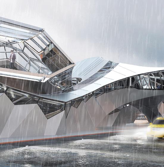

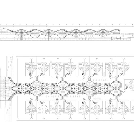

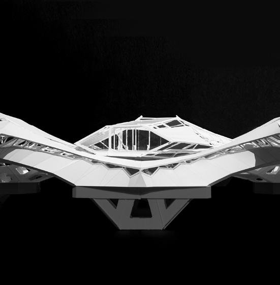
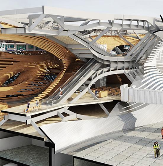
Figure 15 (above left)
A side view of the boarding gate and the interweaving structural geometry of the terminal.
Project credit: Tian Ouyang and Jasmine Gao.
Figure 16 (above middle)
Sectional perspective of the terminal showing the boarding gate on the top and the circulation of passengers and cargo transport through the terminal. Project credit: Tian Ouyang and Jasmine Gao.
Figure 17 (above right)
The plan and section of the interweaving terminal. Project credit: Tian Ouyang and Jasmine Gao.
Figure 18 (below left)
A view of the physical scale model of the terminal showing how the interweaving parts only share the circulation core with each other. Project credit: Tian Ouyang and Jasmine Gao.
Figure 19 (below middle)
Another view of the terminal model representing the integration of structural and architectural geometry. Project credit: Tian Ouyang and Jasmine Gao.
Figure 20 (below right)
Sectional perspective view of the terminal revealing the structural system and architectural components of the interior as well as the facade of the terminal. Project credit: June Zhu, Linnan Yu,and Yiwei Gao.

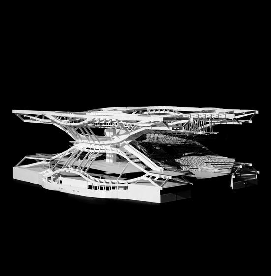
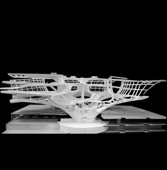
Figure 21 (above left)
Interior view of the terminal with the gates on the top floor, at which the passengers can directly arrive via the air train suspended from the ceiling of the terminal. Project credit: June Zhu, Linnan Yu,and Yiwei Gao.
Figure 22 (above middle)
A sectional perspective of the terminal representing various modes of transportation and architectural space within the terminal. Project credit: Zehua Qi and Qi Liu.
Figure 23 (above right)
Another structural model of a terminal where the internal space is designed as a multi-story spaces to receive drones on the top and conventional airplanes on the side. Project credit: Zhou Xieyang and Duan Xiaoyu.
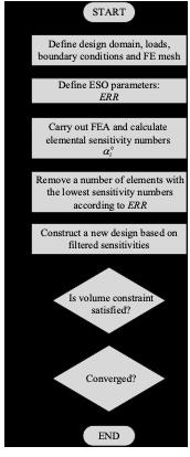
Therefore, some elements that were assigned a solid material in the previous iteration are excluded from the contours in this computation, while some elements that have been previously set to empty material are delineated in this calculation. Within the contour line, XESO achieves bi-directional evolutionary optimization in the process of computation.
Additive Evolutionary Structural Optimization (AESO)
The original ESO algorithm was optimized by progressively removing inefficient materials in an initial design domain full of solid materials. Since the method was proposed in 1992, many scholars have modified some aspects of ESO from different perspectives to meet different design requirements. The Additive ESO method, published in 2000 by Osvaldo Querin, Grant Steven, and Mike Xie, explored the structural transformation from the evolutionary direction of developing from less to more.[9] It provides a basis for the improvement of the subsequent bi-directional evolutionary structural optimization method.
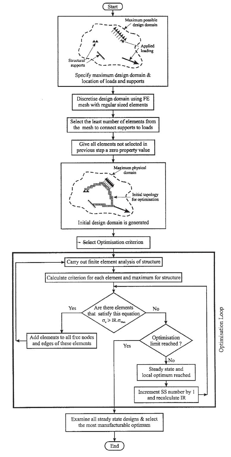
The logic of AESO algorithm is that, firstly, the finite element mesh is divided within a large initial design domain and only solid materials are set for the elements on the necessary path connecting the support and the load areas while most of the other elements are empty material to ensure that the finite element calculation can be carried out; then, the empty material element, near the position where the force is larger, is reset to a solid material through iterative computation to achieve the purpose of increasing the material. The mathematical description of the basic problem of the AESO algorithm is as follows:
f (X ) =
where, σ v i m , K i , U i , and Fi are, respectively, the paradigm equivalent stress, stiffness matrix, displacement matrix, and external force of the i-th element in the design domain. PI , σmax and P are the Performance Index of the entire structure, the largest paradigm equivalent stress and force matrix in the overall design domain.[10] According to the experience, IRss and η i are the Inclusion Ratio of the ss - th iteration and the Addition Multiplier of the i-th unit, as shown in the formula (12),
Figure 3
Flow chart of ESO method.
Figure 4
Illustration of the model update based on the contour line of the XESO method.
Figure 5
XESO bidirectional evolution diagram.
Figure 6
Evolutionary process with XESO.
Figure 7
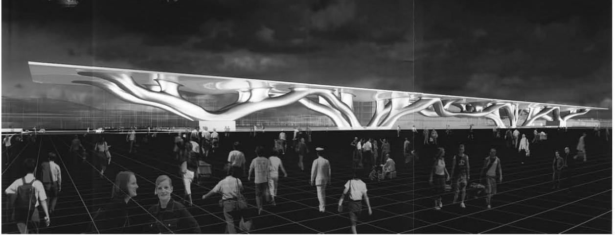
Rendering of Firenze New Station Project. Architect: Arata Isozaki.
t = 1 – q a i q p i + q a i
q a i = q m i ax + q p i
In the above formula, q p i and q m i ax are the sum of the pseudo-density of the element around the i-th unit and its own and the total number of its surrounding elements, respectively.2 For example, for a twodimensional quadrilateral shell element, there are 8 adjacent elements around each element in the center including itself, q m i ax = 9, but for a
2 Pseudo density is a virtual density, which is the material parameter of an element given in topology optimization in order to distinguish whether the element is to be deleted. The closer the pseudo density is to 0, the softer the material of the element, the more it should be deleted; on the contrary, the closer the pseudo density is to 1, the more solid the material of the corresponding unit is and should be retained. In the SIMP method, the pseudo-density of elements is between 0 and 1, while in the ESO/BESO method, the pseudo-density of elements should take the values between 0 and 1.


INTELLIGENT FORCE PRINTING
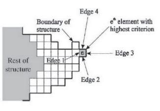
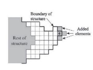
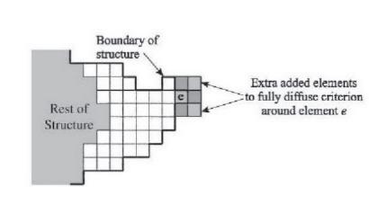
three-dimensional hexahedral element, the value of q m i ax is 27. For the element e in the (Figure 8), before adding the element, there are four solid elements around each element including itself, and their pseudodensity is 1 while the other five elements are void elements; the pseudo density is 0, so its corresponding q p i value is 4.
According to the above operation logic, the flow of AESO algorithm is shown in (Figure 9)
Bi-directional Evolutionary Structural Optimization (BESO)
With the increasing influence of the ESO, many improved algorithms based on ESO have received a lot of attention. Because the initial ESO algorithm can only remove elements, but not add them, many researchers have begun to focus on how to simultaneously delete and add elements in an iterative process, and related studies have adopted similar logic to ESO through setting two parameters— Inclusion Ratio IR and Rejection Ratio RR—and respectively adjusting the ratio of each addition and deletion of elements.[11,12] However, the setting and adjustment of these two parameters have become key factors for the success of the algorithm development. Some studies have pointed out that this framework has a convergence problem; the ESO algorithm, and the 0/1 topology optimisation problem in its improved algorithm, also causes some defects in solution.[13-15] In view of the above problems, Xiaodong Huang and Mike Xie proposed a new Bi-directional Evolutionary Structural Optimization (BESO) method in 2007, and then carried out several update versions.[16-18] 3
Mathematical Description of the BESO Algorithm
In the static analysis of FEM, for the whole structure there is: KU = F
where,K, U, F are the stiffness matrix, displacement matrix, and external force matrix of the overall structure, respectively. The topology optimization problem oriented to the overall strength of the structure can be expressed as: min C (X ) = 1 F T U 2
3 Since there are many versions of the BESO algorithm in history, the BESO framework that appears below mainly refers to the latest version published by Zhihao Zuo and Yi Min Xie in 2015. (13) (15) (14)
8
Illustration of the unit increase method in the 10 AESO algorithm
9
Flow chart of AESO method.
ESSAYS
Figure
Figure


where, C, X, U, K, V * are the objective function (compliance), design variable matrix, displacement matrix, global stiffness matrix, and target volume, respectively. While the v i and xi is the volume and the design variable—pseudo-density—of the i-th element. Since there is no gray level element in the BESO method—that is, in the process of structural evolution—the state of the element is to be deleted and retained as much as possible, so there are only two pseudo-density values.4 In order to ensure the mathematical rigor of the algorithm and avoid the singularity of the stiffness matrix, the pseudo-density of the element can be set to a number far less than 1 (such as 0.000001) and 1. Such a BESO algorithm is called Soft Kill, and the BESO algorithm with element pseudo-density set to 0 and 1 is called Hard Kill.
Then, according to the formula (14), the two sides of the equation are differentiated for the topology optimization variables xi , where there are:
Through the Adjoint Method, to introducing the Lagrange multiplier λ and (F - KU ) the formula (14), namely:
4 In the topology optimization, the solid element with a pseudo-density of 1 is black, the void element with a pseudo-density of 0 is white, and an intermediate element with a pseudo-density between 0 and 1 is gray.
Figure 10
Evolutionary process of Michell structure with AESO method.
The formula (16) becomes:
dC = 1 dF T U + 1 F T dU + dF T + (F - KU) + λ T ( dFdK U-K dU ) dxi 2 dxi 2 dxi dxi dxi dxi dxi
from the formula (13) that the third term in the above formula is 0, and according to the optimization conditions, the external force on the structure will not change, as , therefore, the formula (18) can be simplified as:
dC =( 1 F T -λT K) dU -λ T dK U dxi 2 dxi dxi
known from the formula (13), λ is arbitrary, and since it is difficult to obtain , therefore , as , the formula (19) can be further simplified as:
dC =1 U T dK U dxi 2 dxi
On this basis, according to the material interpolation assumption, the relationship between the elastic modulus of the material and the pseudo-density can be expressed as an exponential function, such as Eq (21), so that the global stiffness matrix of the overall structure can be K.[19] It is represented by the real material stiffness matrix and corresponding pseudo-density of each element xi (formula (22)):
E l and E l are respectively the elastic modulus of the material and the element stiffness matrix when the ith finite element element is filled with the solid material E l. Therefore, the influence degree , of the i-th element’ s pseudo-density change on the structural compliance is called the Sensitivity Number, according to the formula (20) and (22), there are: (18) (19)
1 F T -λ T K = 0 2 λ= 1 U 2 (20) (21) (22)
E (x a i ) = E l ∙ x p i K =∑x p i k l i i
Yuhan Bao
INTELLIGENT FORCE PRINTING
Form Diagram
Form Diagram Force Diagram Force Diagram
Form Diagram
Force Diagram
Form Diagram
Force Diagram
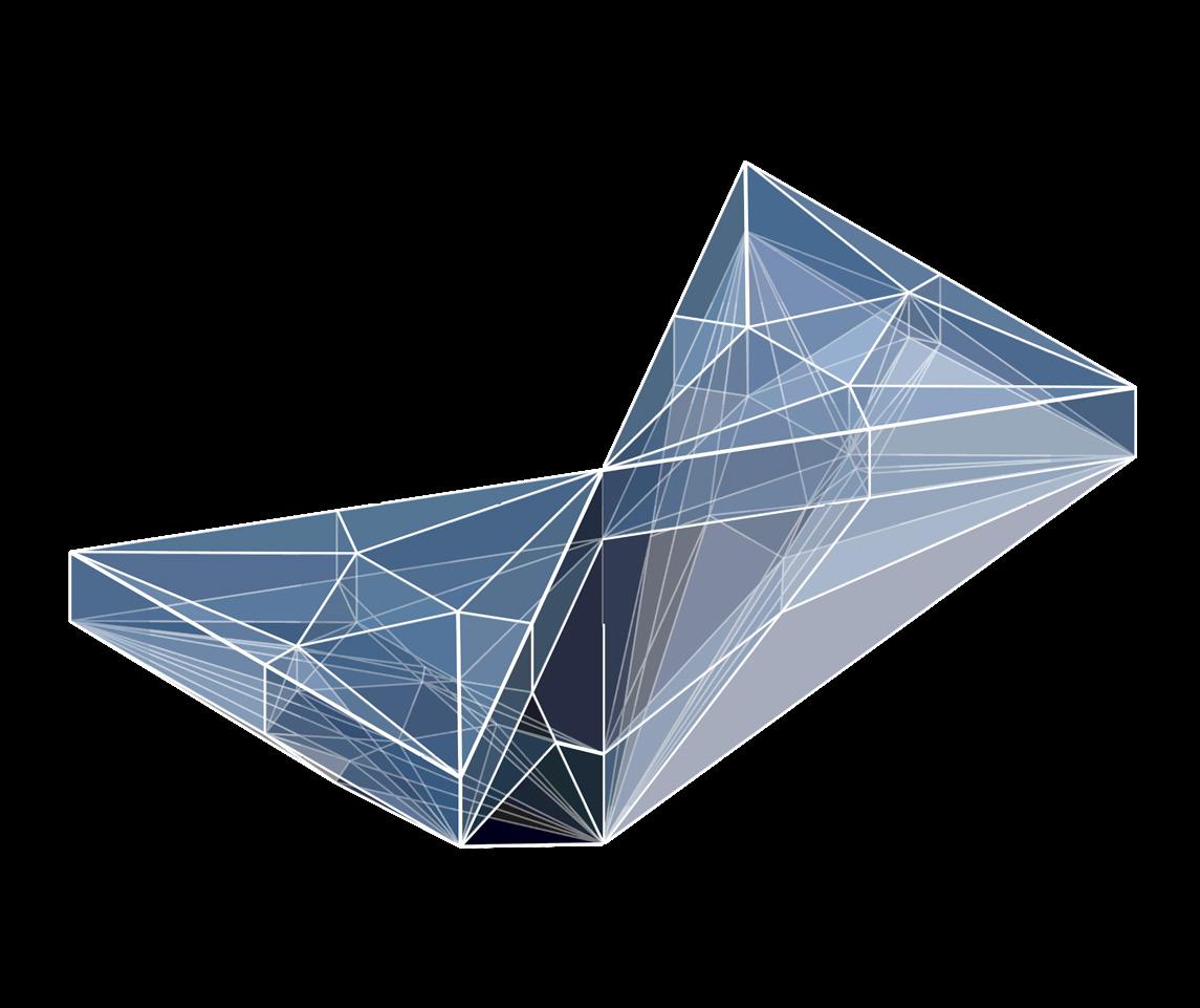
Form Diagram
Force Diagram
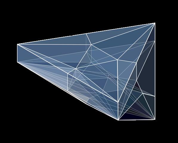
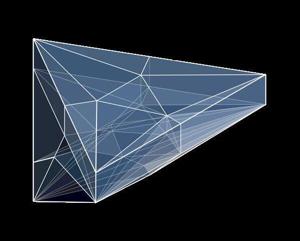
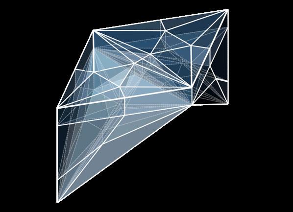



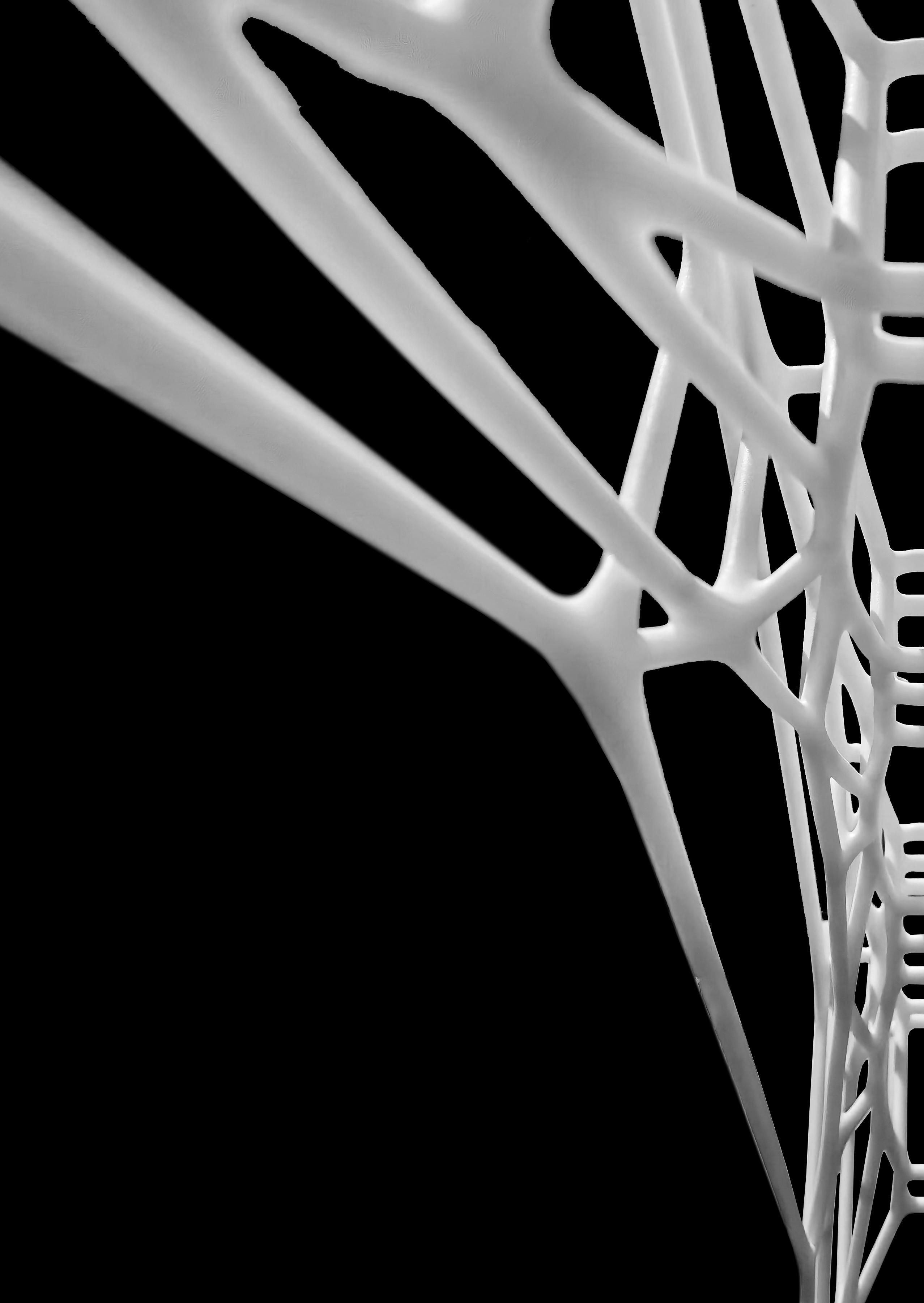
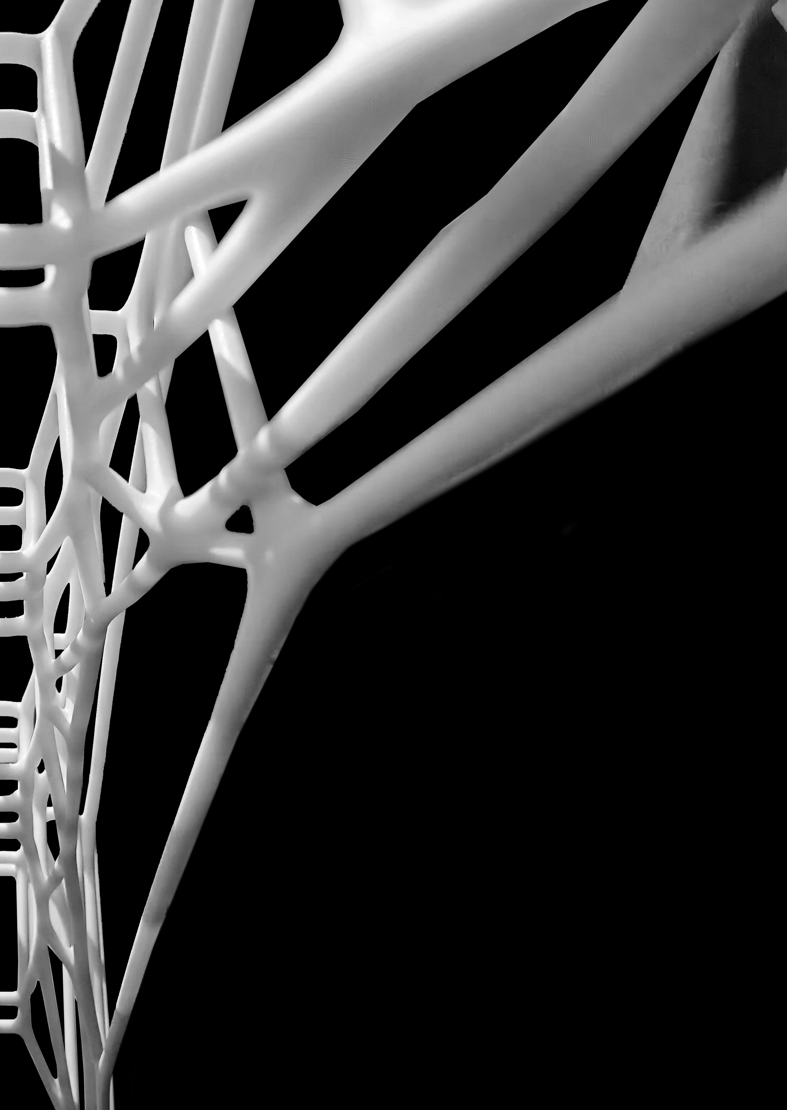
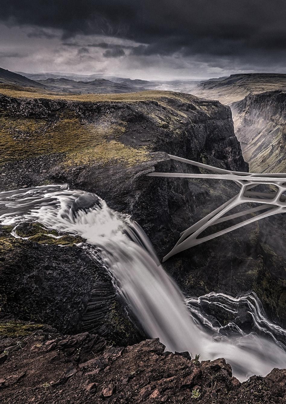

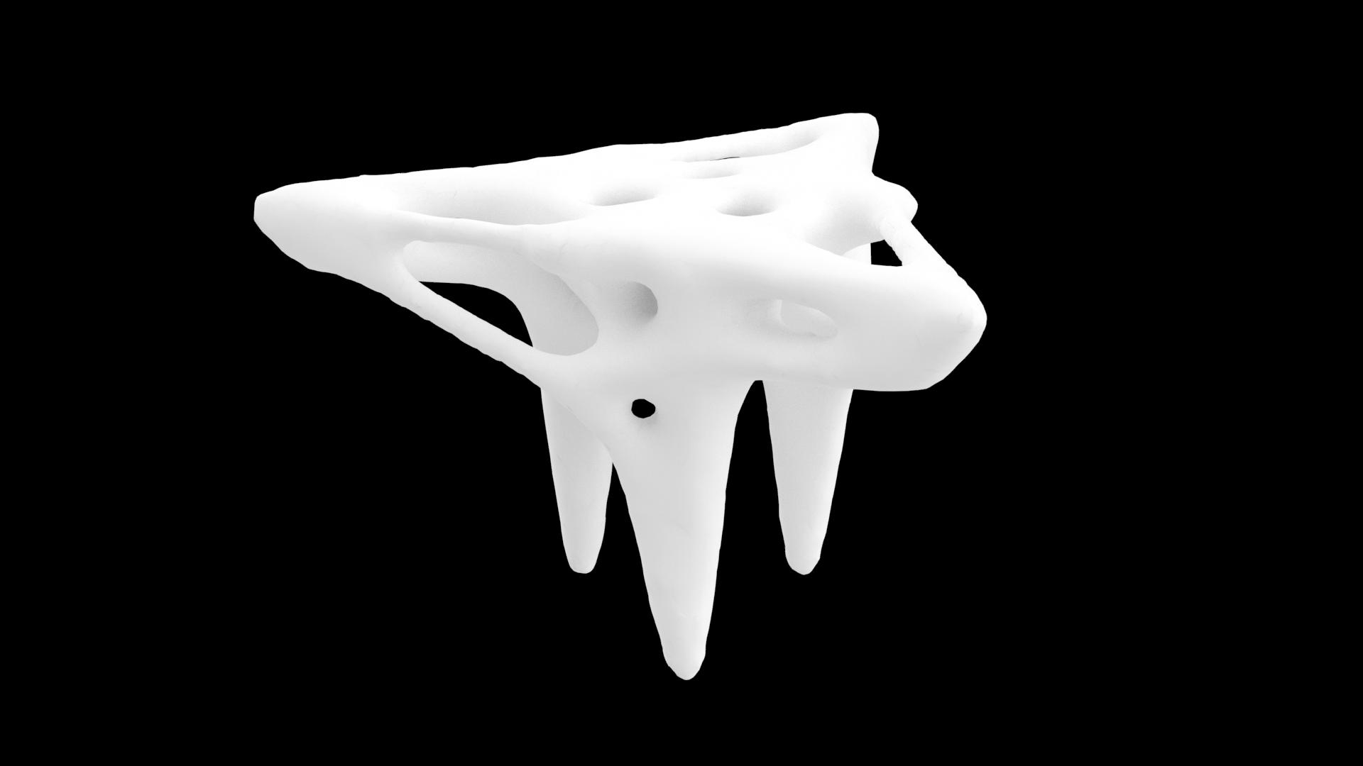
Design Iterations







INTELLIGENT FORCE PRINTING
Introduction
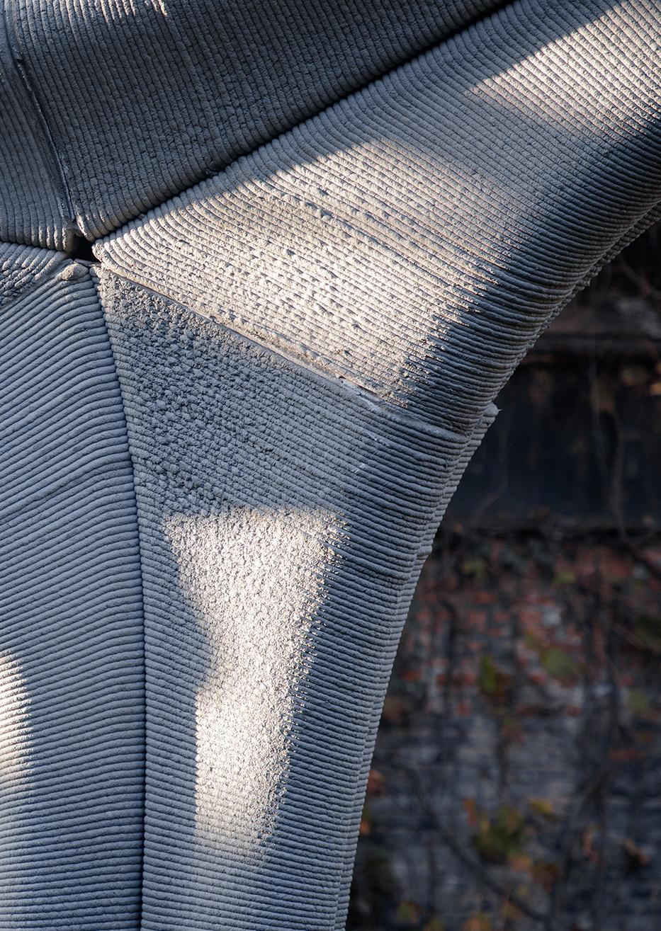
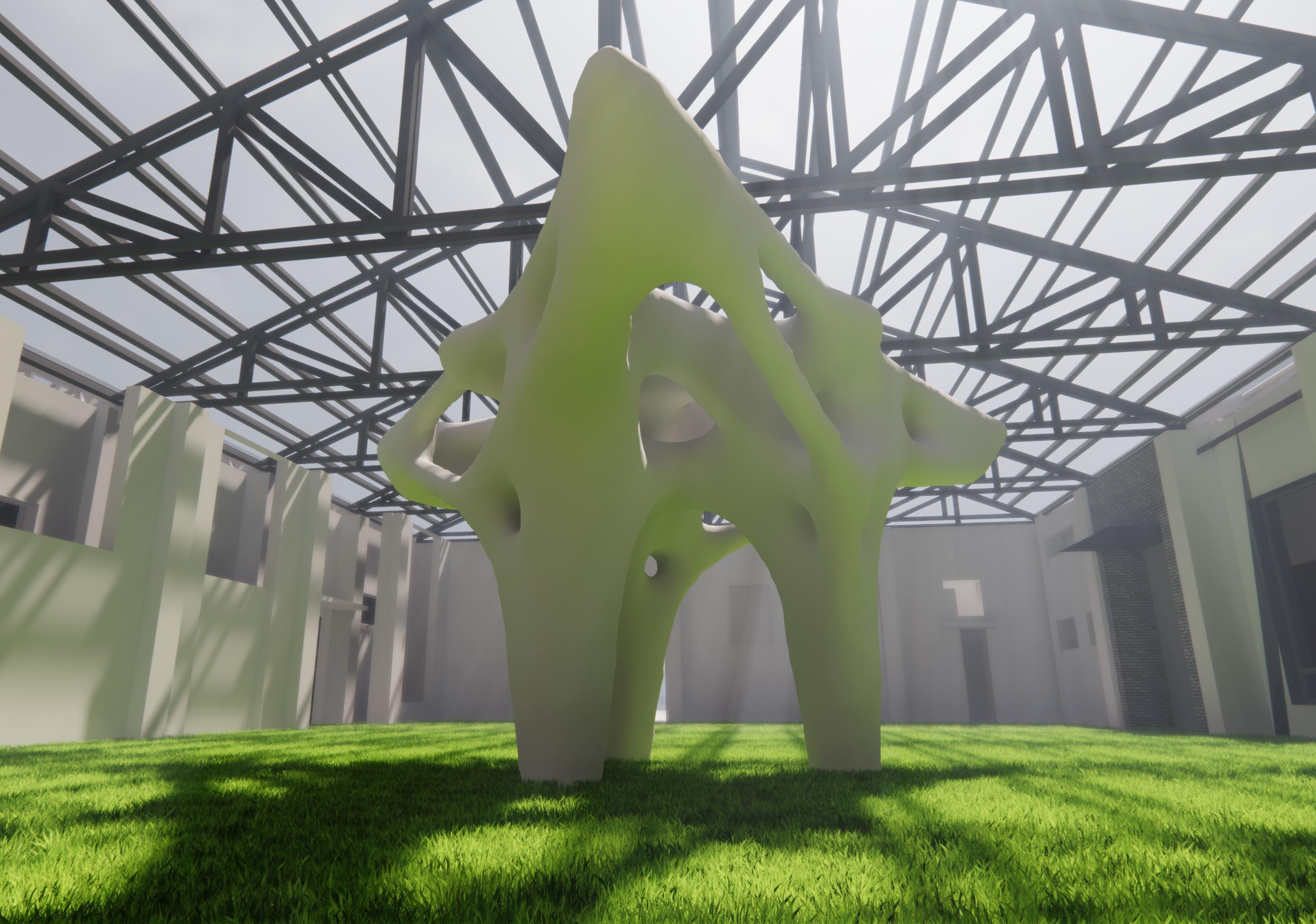
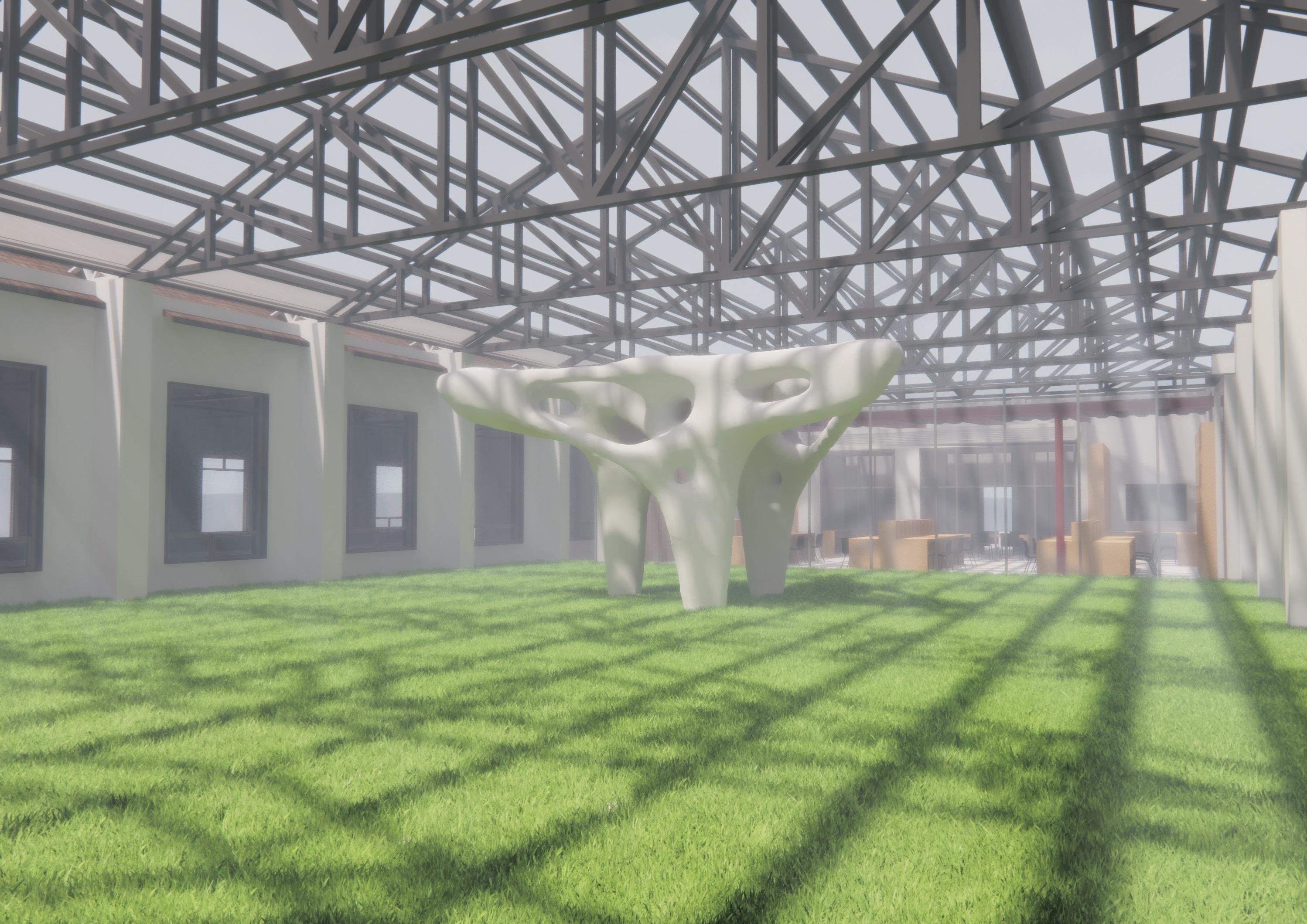
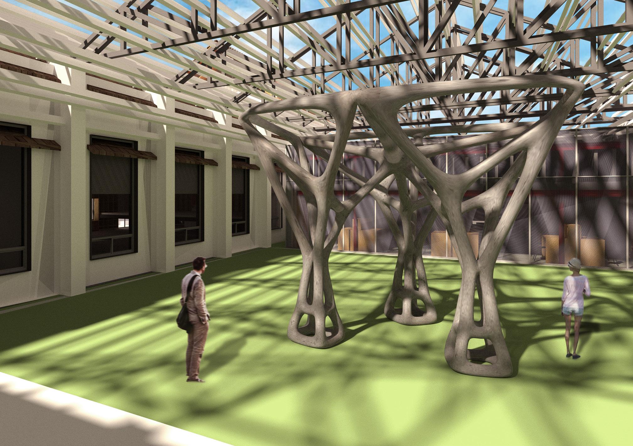
Our intelligent printing pavilion is on the courtyard of Archi-Union’s office, which could fit our pavilion of about 6m by 6m with 3m height. The model was printed directly by the 3D printing robot, and the material is cement.
0m 10m 1m2m5m
DESIGN DEVELOPMENT
Proposal
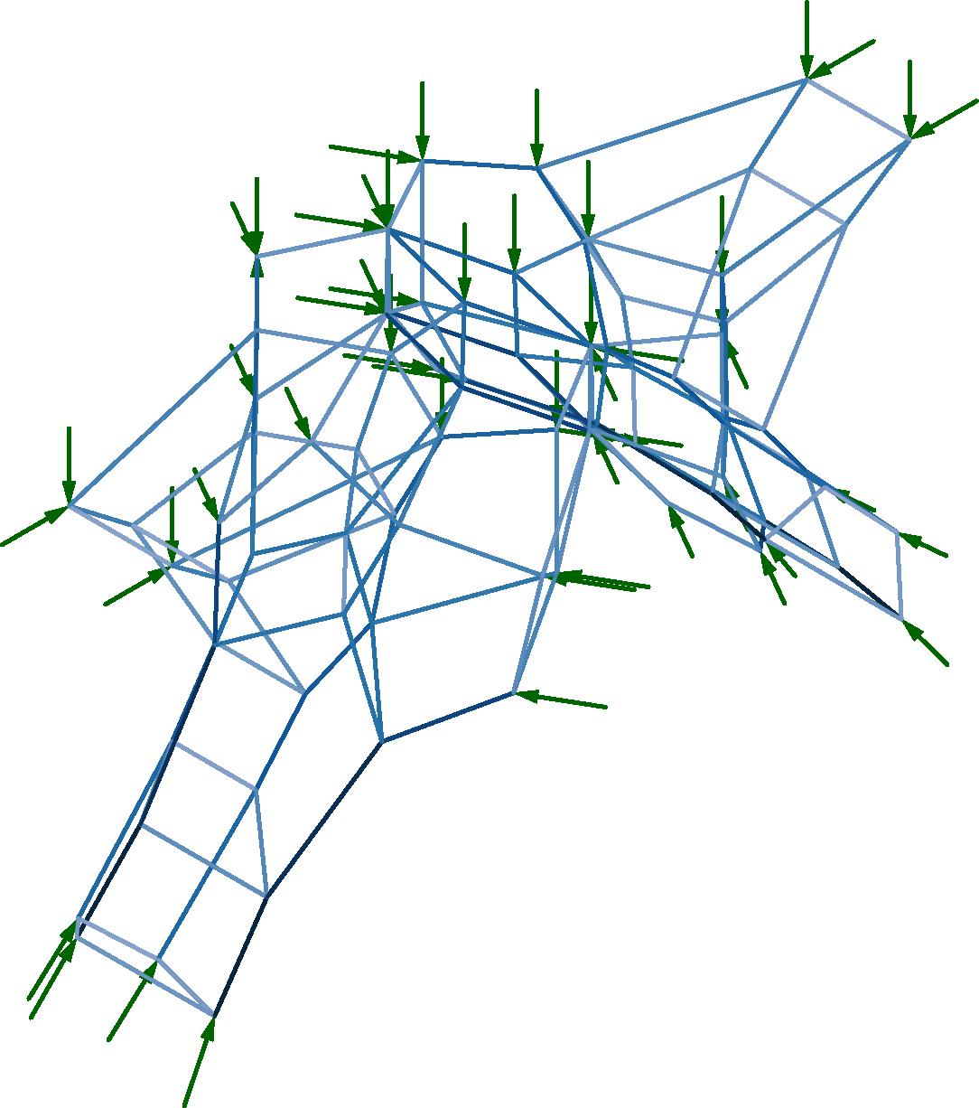
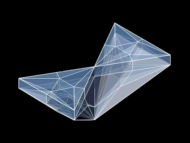
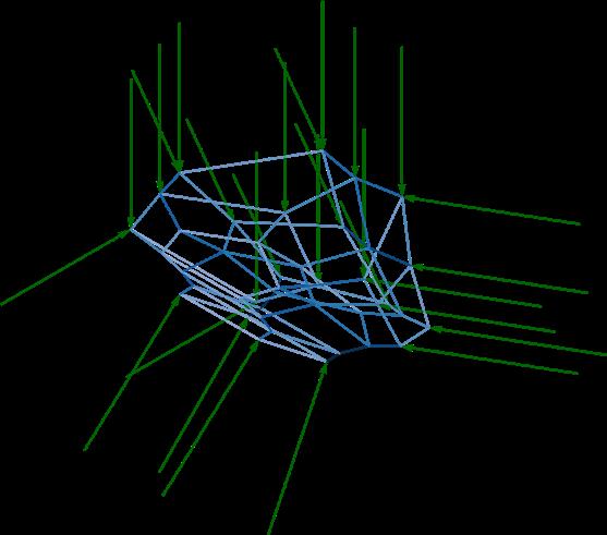
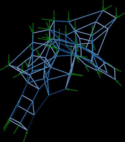
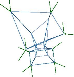
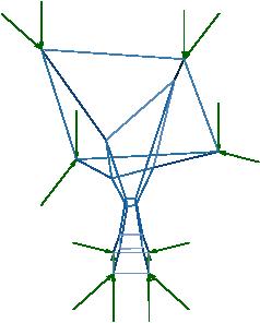
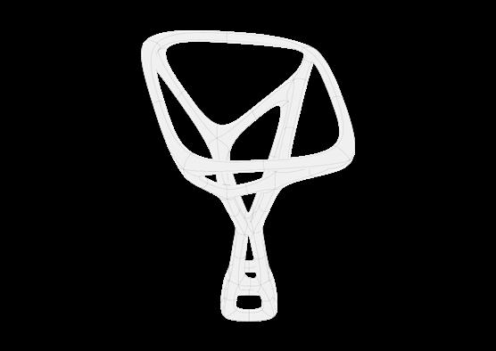
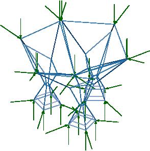
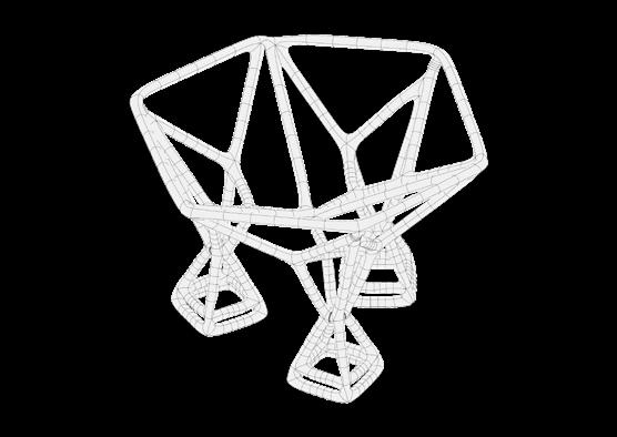
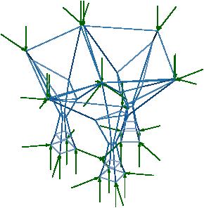
In the project, we combine human and machine with a 3D printing robot as the tool, PolyFrame and Ameba as carrier to realize the geometric structure we designed. Firstly, we designed our pavilion, a three-column structure, where its three parts can support each other to form a stable triangular structure without external support and force. So, we get our initial geometric prototype from it. Then, we use Rhino plug-in PolyFrame to build the Force Diagram through it’s logic and optimal structure, which is the Form Diagram with only three external
supports for each column from the bottom and three external force from top. We integrated Gothic design elements into the original simple member bar, which developed into a single column to a concave-convex arc column with an irregular and vibrant wavy surfaces. The structure was then optimized by Ameba to change the structure from multiple rods to a monolithic one, making the model printable.
INTELLIGENT FORCE PRINTING
Material + Printing Tests
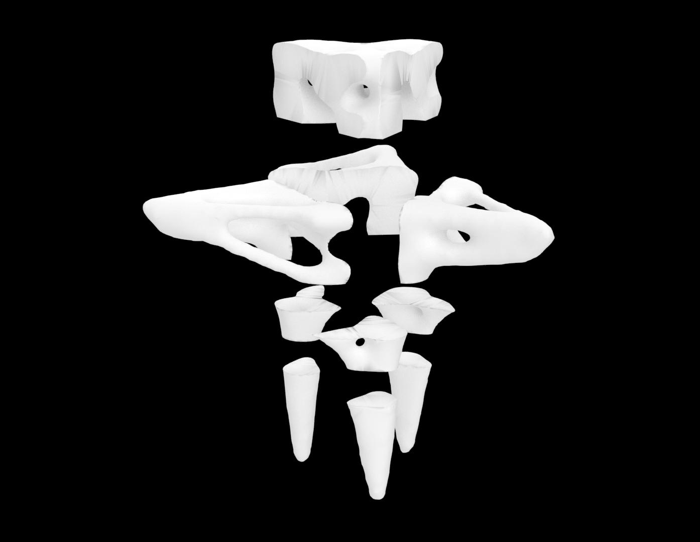
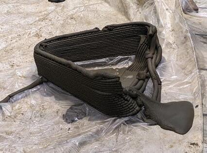
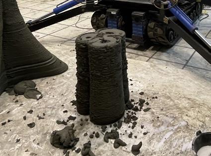
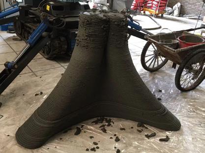
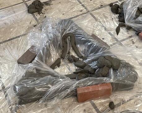
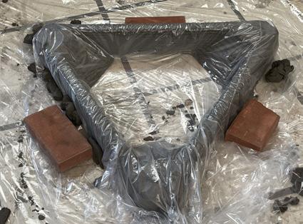
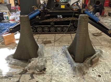
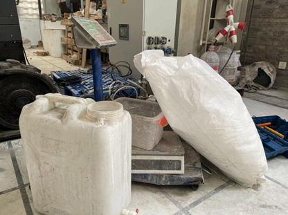
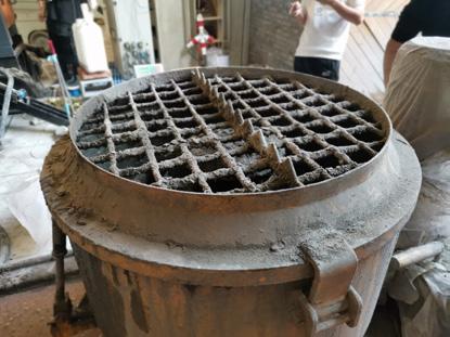
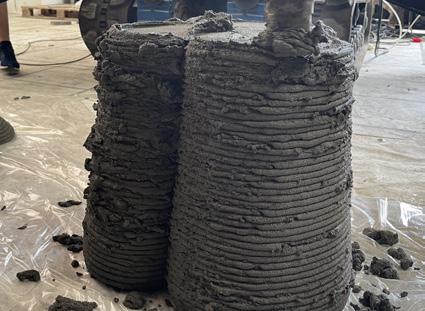
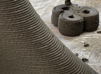
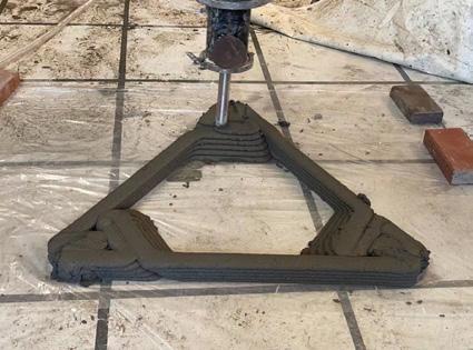
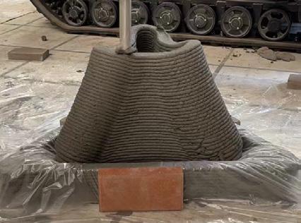
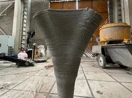
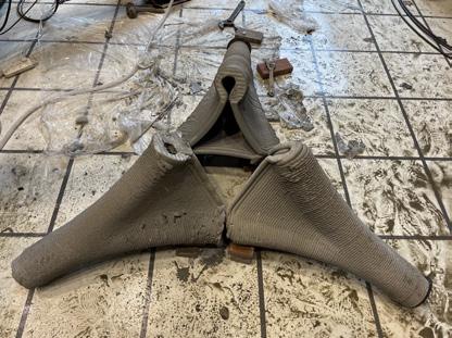
During the design process, the team was also constantly testing for printability. Due to the limitations of cement, the team conducted the following experiments on print path, print angle, and assembly. After many attempts and failures, we came up with the following directions for the challenge of difficult printing. Firstly, it optimized the print on the grasshopper for large slope, secondly, it designed the print foundation and support in order to stabilize our ideal shape, and, finally, the testing pavilion “the print path”. Then,
we optimized the print on the grasshopper for large slope; secondly, we designed the print foundation and support in order to stabilize our ideal shape; and finally, we added reinforcement and steel pieces to the print assembly for tension support at the joints. Finally, we formed our final test pavilion


Initial Tests | Gradient + Height
Pedestal | Tilt 45°
Material Test | Print Quality
DESIGN DEVELOPMENT
Process




Test Pavilion
