
Memorandum
Date July 17, 2025
To
Craig Adair, Crossroads Solar Grazing Center
From Mark Bonifas, P.E., LEED AP
Subject Preliminary Grading Analysis
Project Number 17078
Introduction
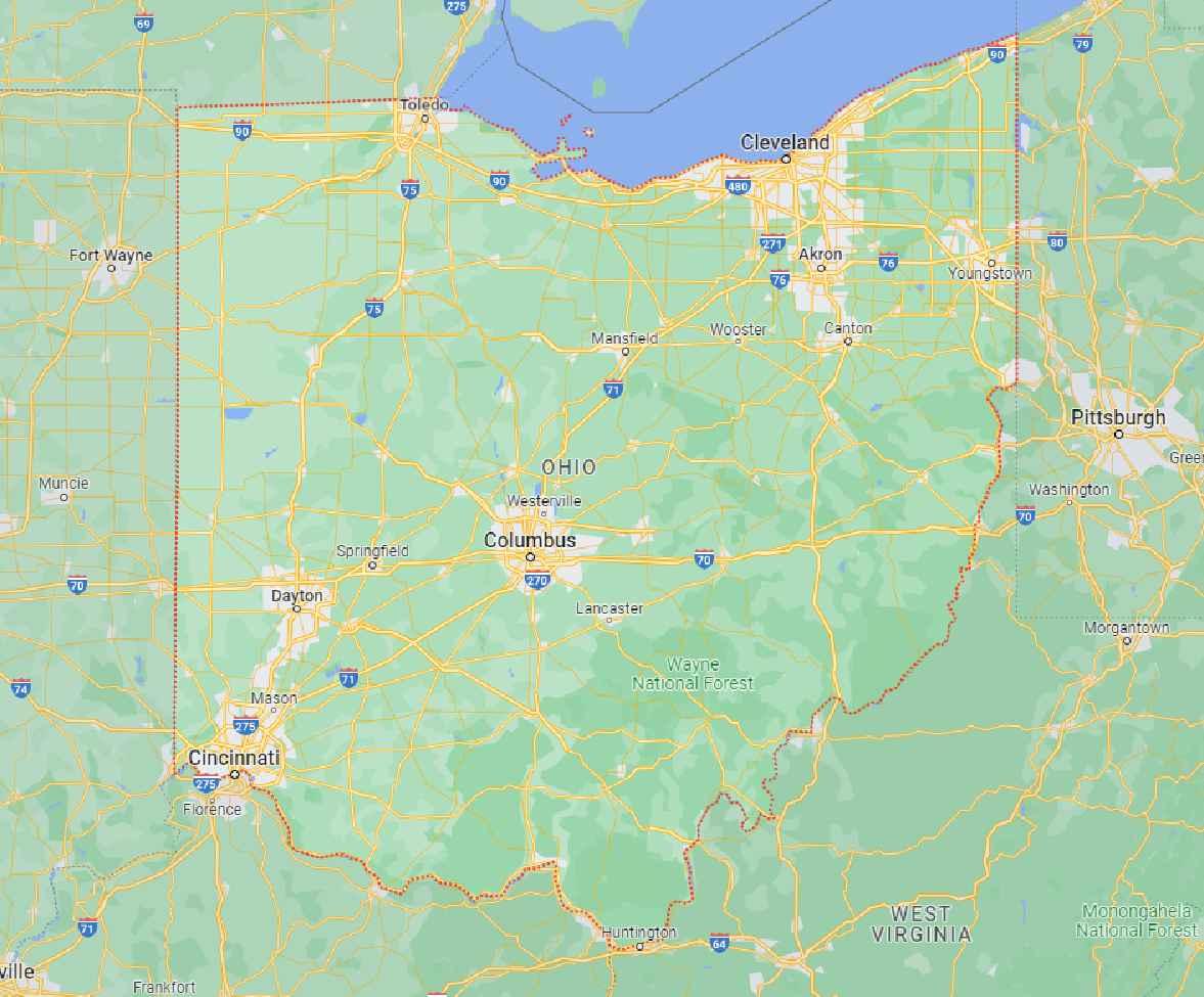
Verdantas has conducted a Preliminary Grading Analysis for the Crossroads Solar Grazing Center (Project) on behalf of Crossroads Solar I, LLC (Client). It includes a Preliminary Grading Plan and estimate of the maximum graded acreage expectation that is responsive to Ohio Administrative Code (OAC) 4906-4-08(A)(5)(b). The Project is a combined utility-scale solar energy and sheep grazing facility in Cardington, Lincoln, and Westfield Townships in Morrow County, Ohio. The Project will use rows of ground-mounted solar panels to supply up to 94 megawatts AC (MWac) of wholesale power to the existing electric grid while also providing pasture for livestock. The Project’s above-ground infrastructure will be located within agricultural-style fences, which also will confine the livestock and protect them from predators. The fenced area will be up to 559 acres (the Solar & Grazing Area) of an area totaling approximately 726 acres (the Project Area).
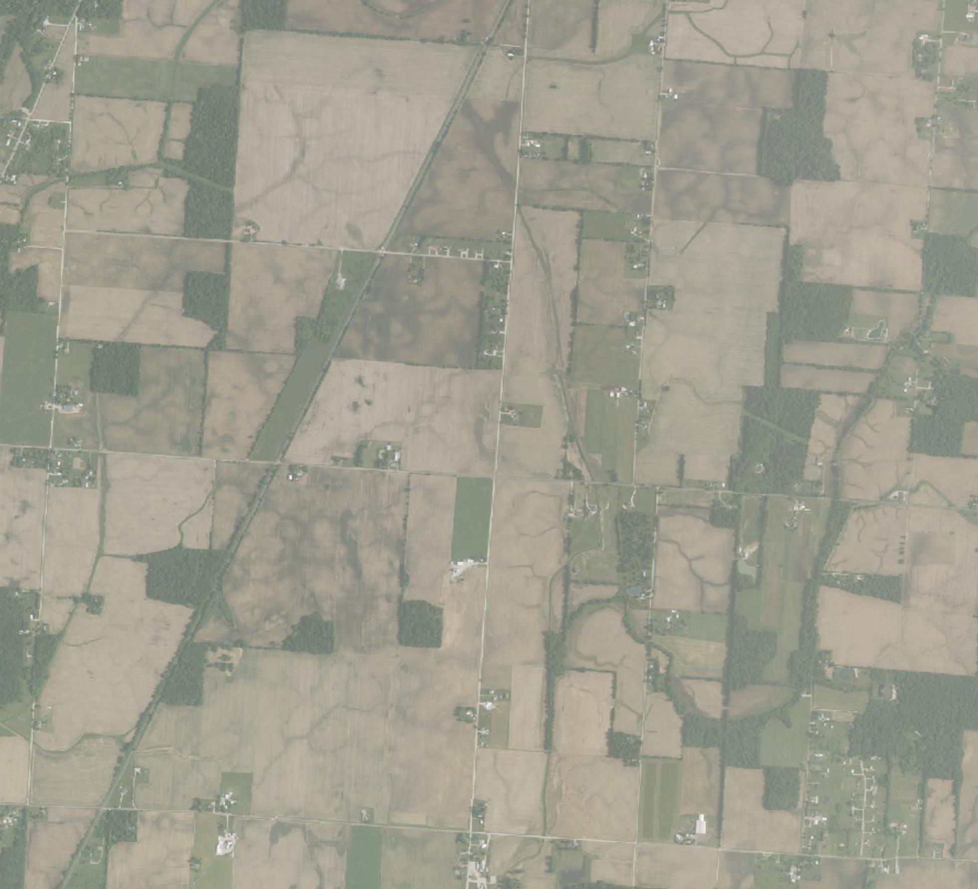
The Project Area consists primarily of tilled agricultural areas, grasslands, internal fence rows, and isolated woodlots. There are a few stream and wetland features within the Project Area that have been avoided to the extent practicable to limit any impact to local wildlife and water resources. There are no areas designated as FEMA regulatory floodway or floodplain zones. The terrain is relatively flat, with an average slope of approximately 3% and an average elevation of approximately 1,001 feet above mean sea level (msl).
Preliminary Grading Analysis
This section outlines the approach used for the grading analysis, the estimated total amount of earthwork (cut and fill) in cubic yards, as well as the estimated graded acreage expectation for the Project Area The preliminary grading analysis provides a sufficient understanding of the Project’s scope and requirements in terms of total expected cut/fill volumes and estimated grading acreage. These values are subject to change during the detailed design of the final PV layout, the racking technology specified, a final geotechnical study, as well as final electrical design.
Assumptions for Analysis
1. Minimum Pile Reveal:


Verdantas assumed a minimum pile reveal of 5.7 feet, which corresponds to a minimum module ground clearance of 2 feet for operation and maintenance purposes using a representative Q.CELLS Q.PEAK DUO ML-G12S.3/BFG PV module For purposes of this evaluation, Verdantas used a maximum pile reveal of 7.7 feet to accommodate terrain undulations and maintain racking installation tolerances.
2. Racking Type:
Verdantas assumed standard single-axis tracker racking instead of terrain-following racking. This choice reflects a worst-case scenario, providing a realistic but conservative estimate of the estimated earthwork. Should terrain-following racking be implemented, a reduced quantity of cut and fill is anticipated, along with a reduced acreage of disturbance. For this analysis, a representative racking system from Game Change was used.
3. Temporary Sediment Basin Assumptions:
• Pond Volume: 104 cubic yards per acre drained (1,800 ft3/acre for dewatering and 1,000 ft3/acre for sediment storage)
• Pond Depth: 5 feet
• Additional Earthwork Contingency: 1.5
Setbacks
Assumed setbacks within the Project Area:
• 50 feet from non-participating parcel boundaries to solar panels
• 300 feet from non-participating residences to solar panels
• 500 feet from non-participating residences to inverters
• 50 feet from jurisdictional waterways to fenceline
• 120 feet from jurisdictional wetlands to fenceline
• 150 feet from the public road edge of pavement to solar panels
• 50 feet from ODNR-mapped water wells to solar panels
• 50 feet from ODNR-mapped active oil and gas wells to solar panels
• 25 feet from ODNR-mapped inactive oil and gas wells to solar panels
Calculations
1. Preliminary Grading
In many situations, PV array racking technology can follow the existing contours of the ground and do not require any grading for construction. The areas under the PV arrays were analyzed using PVcase, an industry leading software that incorporates the module specifications and racking tolerances to determine where areas might need grading to stay within the specified tolerances. The Preliminary Grading Plan (attached as Attachment A) shows the probable areas of grading including a color contoured key for depth of earthwork cut and fill.
Generally, the Ohio Power Siting Board (OPSB) defines grading as: “Grading includes earthmoving activities incidental to building roads, equipment pads, substation, and laydown yards, installing buried electric lines, excavating stormwater basins, performing soil removal activities, soil filling activities, and cut-and-fill activities.”

OPSB also generally provides that, “Grading does not include routine ground disturbance incidental to installing piles, drain tile, fences, poles for electric lines, vegetation, landscaping, and temporary erosion and sediment controls, performing soil sampling, geotechnical investigations, archaeological investigations, disking topsoil to promote growth of vegetation, and raking, smoothing ruts, or otherwise creating a smooth and safe work surface.”
To align with this approach, Verdantas has calculated the estimated graded acreage expectation by summing the acreage of estimated grading for the PV array areas and other features including:
• access roads (road width of 16 feet)
• temporary laydown areas (as shown on the Preliminary Maximum Site Plan)
• the Project Substation, Utility Switchyard, and Operations & Maintenance Building (as shown on the Preliminary Maximum Site Plan)
• inverters (165 square feet each)
• temporary sedimentation basins (see below)
• collection line trenching (trench width of 16 inches)
2. Temporary Sediment Basin Sizing
The Project Area is expected to be pre-vegetated prior to construction with a temporary or permanent seed mix to provide erosion control. Due to the relatively flat topography of the Project Area, it is anticipated that typical sediment barriers such as silt fence and filter socks would be used to manage sediment for the majority of the site during construction Temporary seeding is expected to be used during construction as needed to stabilize pre-vegetated areas that are further disturbed. In the event additional sediment control is necessary, other sediment control methods such as temporary sediment basins are expected to be utilized. As a conservative approach for this analysis, the earthwork calculations include a temporary sediment basin for each drainage area within the Project Area. In practice, the number of temporary sediment basins needed is expected to be less. Once construction is finished and the Project Area is stabilized, the temporary sediment traps are expected to be filled in and the disturbed area restored.
To estimate the volume of temporary sediment basins, Verdantas utilized the standard sediment basin sizing criteria per the Ohio EPA NPDES General Permit Authorization for Stormwater Discharges Associated with Construction Activity (OHC000006). The General Permit states that the “The volume of the dewatering zone shall be a minimum of 1800 cubic feet (ft3) per acre of drainage (67 yd3 /acre)…. The volume of the sediment storage zone shall be 1000 ft3 per disturbed acre within the watershed of the basin”. Verdantas has assumed a 5-foot-deep pond with 1 foot of freeboard. To account for the additional earthwork associated with constructing these temporary sediment basins (berms, spillways, benches, etc.), Verdantas has applied an additional contingency of 1.5 for earthwork calculations.
A summary of the earthwork and estimated grading area expectation is provided in Table 1 and Table 2 below, respectively
Notes:
A – These features are expected to be temporary during construction and are expected to be restored at construction completion; therefore, the cut and fill volumes are the same.

Table 1: Total Earthwork
Table 2: Estimated Grading Acreage Expectation
(28 inverters, 165 square feet each)
(total length of 40,569 feet, 16-inch width)
Findings
The preliminary grading analysis shows that there is a low percentage of the Project Area that is likely to have impacts from grading. This is primarily due to the relatively flat topography of the land in the Project Area and expected avoidance of localized areas of topography change such as near streams and wetlands. These preliminary findings provide a sufficient understanding of the Project’s scope and requirements in terms of total expected cut/fill volumes and estimated grading acreage. However, it is important to understand that these values are subject to change during the detailed design of the final PV layout, the racking technology specified, a final geotechnical study, as well as final electrical design. If you have any questions, please contact us as shown below.
Respectfully, VERDANTAS

Liam Schlueter Engineer II
614-362-3593
lschlueter@verdantas.com
References

Mark J. Bonifas, P.E., LEED AP Senior Consultant

614-362-7288
mbonifas@verdantas.com
• https://codes.ohio.gov/ohio-administrative-code/4906
• https://epa.ohio.gov/divisions-and-offices/surface-water/guides-manuals/rainwater-andland-development
• https://dam.assets.ohio.gov/image/upload/epa.ohio.gov/Portals/35/permits/OHC000006. pdf
ATTACHMENT A
Preliminary Grading Plan

PRELIMINARYGRADINGPLAN
CROSSROADSSOLARGRAZINGCENTER
MORROWCOUNTY,OHIO


SYSTEMSPECIFICATIONSFORREPRESENTATIVECOMPONENTS
INVERTERQUANTITY


NOTES:
1.EXCEPTFORTHESYSTEMSIZEAC,THESYSTEMSPECIFICATIONSARE PRELIMINARYANDSUBJECTTOCHANGEBASEDONFINALDESIGN.


LEGEND


PROJECTAREA
FENCELINE
ACCESSROAD
COLLECTIONLINEEASEMENT
PROJECTSUBSTATION,SWITCHYARD,ANDO&MBUILDING
SOLARARRAY
INVERTER
SITEENTRANCE
TEMPORARYLAYDOWNAREA

DELINEATEDPEMWETLAND(EXISTING)

DELINEATEDPFOWETLAND(EXISTING)
DELINEATEDWATERWAY(EXISTING)
ROADRIGHT-OF-WAY(EXISTING)
EDGEOFROAD(EXISTING)
OVERHEADELECTRICLINE(EXISTING)
PROPERTYLINE(EXISTING)
RAILROAD(EXISTING)
BUILDING(EXISTING)
NON-PARTICIPATINGPARCELBOUNDARYTOSOLARPANELS 50'MIN.
NON-PARTICIPATINGRESIDENCETOSOLARPANELS 300'MIN.
NON-PARTICIPATINGRESIDENCETOINVERTERS 500'MIN.
JURISDICTIONALWATERWAYTOFENCELINE 50'MIN.
JURISDICTIONALWETLANDTOFENCELINE 120'MIN.
PUBLICROADSETBACKS(EDGEOFPAVEMENTTOPANELS) 150'MIN.
WELLSETBACKS
WATERWELL(ODNR)TOSOLARPANELS 50'MIN.
ACTIVEOIL/GASWELL(ODNR)TOSOLARPANELS 50'MIN.
INACTIVEOIL/GASWELL(ODNR)TOSOLARPANELS 25'MIN.
NOTES:
1.THISDRAWINGISPRELIMINARYINNATUREANDFORILLUSTRATIVEPURPOSES ONLY.
2.THEFENCELOCATIONSDEPICTEDINTHISDRAWINGREPRESENTTHE "MAXIMUMEXTENT"OFTHEFENCEDAREAFORTHEPROJECT.FACILITY COMPONENTLOCATIONSARESUBJECTTOCHANGEBASEDONDETAILED DESIGN,ACTUALSITECONDITIONS,ANDTHESETBACKSLISTEDHEREIN.
3.SITETOINCLUDE16'WIDEACCESSROADS.
4.TURNINGRADIUSONROADSTOBE35'TYPICAL.
5.UNDERGROUNDPIPINGFOROIL/GASWELLSAREKNOWNTOBELOCATEDIN THEPROJECTAREA.CONTRACTORTOWORKWITHTHEOIL/GASWELLOWNER TOLOCATETHEUNDERGROUNDPIPINGDURINGFINALDESIGNSOTHATIT CANBEAVOIDEDORREROUTED.
6.COLLECTIONLINESEXPECTEDTOBECONSTRUCTEDVIAHORIZONTAL DIRECTIONALDRILLING(HDD)ATROAD,STREAM,ANDWETLANDCROSSINGS.
LEGEND
SHEETMATCHLINE
FENCELINE
ACCESSROAD
COLLECTIONLINEEASEMENT

PROJECTSUBSTATION,SWITCHYARD,ANDO&MBUILDING
SOLARARRAY
INVERTER
SITEENTRANCE
TEMPORARYLAYDOWNAREA
SURFACEFLOWDIRECTION


DELINEATEDPEMWETLAND(EXISTING)
DELINEATEDPFOWETLAND(EXISTING)
DELINEATEDWATERWAY(EXISTING)
ROADRIGHT-OF-WAY(EXISTING)
EDGEOFROAD(EXISTING)
OVERHEADELECTRICLINE(EXISTING)
PROPERTYLINE(EXISTING)
RAILROAD(EXISTING)
BUILDING(EXISTING)
ACTIVEOIL/GASWELL(EXISTING)
PLUGGED/ABANDONEDOIL/GASWELL(EXISTING)
EXPIREDPERMITOIL/GASWELL(EXISTING)
DRYHOLEGASWELL(EXISTING)
WATERWELL(EXISTING)


LEGEND
SHEETMATCHLINE
FENCELINE
ACCESSROAD
COLLECTIONLINEEASEMENT

PROJECTSUBSTATION,SWITCHYARD,ANDO&MBUILDING
SOLARARRAY
INVERTER
SITEENTRANCE
TEMPORARYLAYDOWNAREA
SURFACEFLOWDIRECTION


DELINEATEDPEMWETLAND(EXISTING)
DELINEATEDPFOWETLAND(EXISTING)
DELINEATEDWATERWAY(EXISTING)
ROADRIGHT-OF-WAY(EXISTING)
EDGEOFROAD(EXISTING)
OVERHEADELECTRICLINE(EXISTING)
PROPERTYLINE(EXISTING)
RAILROAD(EXISTING)
BUILDING(EXISTING)
ACTIVEOIL/GASWELL(EXISTING)
PLUGGED/ABANDONEDOIL/GASWELL(EXISTING)
EXPIREDPERMITOIL/GASWELL(EXISTING)
DRYHOLEGASWELL(EXISTING)
WATERWELL(EXISTING)
1.THISDRAWINGISPRELIMINARYINNATUREANDFORILLUSTRATIVEPURPOSES ONLY.
2.THEFENCELOCATIONSDEPICTEDINTHISDRAWINGREPRESENTTHE "MAXIMUMEXTENT"OFTHEFENCEDAREAFORTHEPROJECT.FACILITY COMPONENTLOCATIONSARESUBJECTTOCHANGEBASEDONDETAILED DESIGN,ACTUALSITECONDITIONS,ANDTHESETBACKSLISTEDHEREIN.
3.SITETOINCLUDE16'WIDEACCESSROADS.
4.TURNINGRADIUSONROADSTOBE35'TYPICAL.
5.UNDERGROUNDPIPINGFOROIL/GASWELLSAREKNOWNTOBELOCATEDIN THEPROJECTAREA.CONTRACTORTOWORKWITHTHEOIL/GASWELLOWNER TOLOCATETHEUNDERGROUNDPIPINGDURINGFINALDESIGNSOTHATIT CANBEAVOIDEDORREROUTED.
6.COLLECTIONLINESEXPECTEDTOBECONSTRUCTEDVIAHORIZONTAL DIRECTIONALDRILLING(HDD)ATROAD,STREAM,ANDWETLANDCROSSINGS.

LEGEND
SHEETMATCHLINE
FENCELINE
ACCESSROAD
COLLECTIONLINEEASEMENT

PROJECTSUBSTATION,SWITCHYARD,ANDO&MBUILDING
SOLARARRAY
INVERTER
SITEENTRANCE
TEMPORARYLAYDOWNAREA
SURFACEFLOWDIRECTION


DELINEATEDPEMWETLAND(EXISTING)
DELINEATEDPFOWETLAND(EXISTING)
DELINEATEDWATERWAY(EXISTING)
ROADRIGHT-OF-WAY(EXISTING)
EDGEOFROAD(EXISTING)
OVERHEADELECTRICLINE(EXISTING)
PROPERTYLINE(EXISTING)
RAILROAD(EXISTING)
BUILDING(EXISTING)
ACTIVEOIL/GASWELL(EXISTING)
PLUGGED/ABANDONEDOIL/GASWELL(EXISTING)
EXPIREDPERMITOIL/GASWELL(EXISTING)
DRYHOLEGASWELL(EXISTING)
WATERWELL(EXISTING)
1.THISDRAWINGISPRELIMINARYINNATUREANDFORILLUSTRATIVEPURPOSES ONLY.
2.THEFENCELOCATIONSDEPICTEDINTHISDRAWINGREPRESENTTHE "MAXIMUMEXTENT"OFTHEFENCEDAREAFORTHEPROJECT.FACILITY COMPONENTLOCATIONSARESUBJECTTOCHANGEBASEDONDETAILED DESIGN,ACTUALSITECONDITIONS,ANDTHESETBACKSLISTEDHEREIN.
3.SITETOINCLUDE16'WIDEACCESSROADS.
4.TURNINGRADIUSONROADSTOBE35'TYPICAL.
5.UNDERGROUNDPIPINGFOROIL/GASWELLSAREKNOWNTOBELOCATEDIN THEPROJECTAREA.CONTRACTORTOWORKWITHTHEOIL/GASWELLOWNER TOLOCATETHEUNDERGROUNDPIPINGDURINGFINALDESIGNSOTHATIT CANBEAVOIDEDORREROUTED.
6.COLLECTIONLINESEXPECTEDTOBECONSTRUCTEDVIAHORIZONTAL DIRECTIONALDRILLING(HDD)ATROAD,STREAM,ANDWETLANDCROSSINGS.


LEGEND
SHEETMATCHLINE
FENCELINE
ACCESSROAD
COLLECTIONLINEEASEMENT

PROJECTSUBSTATION,SWITCHYARD,ANDO&MBUILDING
SOLARARRAY
INVERTER
SITEENTRANCE
TEMPORARYLAYDOWNAREA
SURFACEFLOWDIRECTION


DELINEATEDPEMWETLAND(EXISTING)
DELINEATEDPFOWETLAND(EXISTING)
DELINEATEDWATERWAY(EXISTING)
ROADRIGHT-OF-WAY(EXISTING)
EDGEOFROAD(EXISTING)
OVERHEADELECTRICLINE(EXISTING)
PROPERTYLINE(EXISTING)
RAILROAD(EXISTING)
BUILDING(EXISTING)
ACTIVEOIL/GASWELL(EXISTING)
PLUGGED/ABANDONEDOIL/GASWELL(EXISTING)
EXPIREDPERMITOIL/GASWELL(EXISTING)
DRYHOLEGASWELL(EXISTING)


WATERWELL(EXISTING)
1.THISDRAWINGISPRELIMINARYINNATUREANDFORILLUSTRATIVEPURPOSES ONLY.
2.THEFENCELOCATIONSDEPICTEDINTHISDRAWINGREPRESENTTHE "MAXIMUMEXTENT"OFTHEFENCEDAREAFORTHEPROJECT.FACILITY COMPONENTLOCATIONSARESUBJECTTOCHANGEBASEDONDETAILED DESIGN,ACTUALSITECONDITIONS,ANDTHESETBACKSLISTEDHEREIN.
3.SITETOINCLUDE16'WIDEACCESSROADS.
4.TURNINGRADIUSONROADSTOBE35'TYPICAL.
5.UNDERGROUNDPIPINGFOROIL/GASWELLSAREKNOWNTOBELOCATEDIN THEPROJECTAREA.CONTRACTORTOWORKWITHTHEOIL/GASWELLOWNER TOLOCATETHEUNDERGROUNDPIPINGDURINGFINALDESIGNSOTHATIT CANBEAVOIDEDORREROUTED.
6.COLLECTIONLINESEXPECTEDTOBECONSTRUCTEDVIAHORIZONTAL DIRECTIONALDRILLING(HDD)ATROAD,STREAM,ANDWETLANDCROSSINGS.

LEGEND
SHEETMATCHLINE
FENCELINE
ACCESSROAD
COLLECTIONLINEEASEMENT

PROJECTSUBSTATION,SWITCHYARD,ANDO&MBUILDING
SOLARARRAY
INVERTER
SITEENTRANCE
TEMPORARYLAYDOWNAREA
SURFACEFLOWDIRECTION


DELINEATEDPEMWETLAND(EXISTING)
DELINEATEDPFOWETLAND(EXISTING)
DELINEATEDWATERWAY(EXISTING)
ROADRIGHT-OF-WAY(EXISTING)
EDGEOFROAD(EXISTING)
OVERHEADELECTRICLINE(EXISTING)
PROPERTYLINE(EXISTING)
RAILROAD(EXISTING)
BUILDING(EXISTING)
ACTIVEOIL/GASWELL(EXISTING)
PLUGGED/ABANDONEDOIL/GASWELL(EXISTING)
EXPIREDPERMITOIL/GASWELL(EXISTING)
DRYHOLEGASWELL(EXISTING)
WATERWELL(EXISTING)


1.THISDRAWINGISPRELIMINARYINNATUREANDFORILLUSTRATIVEPURPOSES ONLY.
2.THEFENCELOCATIONSDEPICTEDINTHISDRAWINGREPRESENTTHE "MAXIMUMEXTENT"OFTHEFENCEDAREAFORTHEPROJECT.FACILITY COMPONENTLOCATIONSARESUBJECTTOCHANGEBASEDONDETAILED DESIGN,ACTUALSITECONDITIONS,ANDTHESETBACKSLISTEDHEREIN.
3.SITETOINCLUDE16'WIDEACCESSROADS.
4.TURNINGRADIUSONROADSTOBE35'TYPICAL.
5.UNDERGROUNDPIPINGFOROIL/GASWELLSAREKNOWNTOBELOCATEDIN THEPROJECTAREA.CONTRACTORTOWORKWITHTHEOIL/GASWELLOWNER TOLOCATETHEUNDERGROUNDPIPINGDURINGFINALDESIGNSOTHATIT CANBEAVOIDEDORREROUTED.
6.COLLECTIONLINESEXPECTEDTOBECONSTRUCTEDVIAHORIZONTAL DIRECTIONALDRILLING(HDD)ATROAD,STREAM,ANDWETLANDCROSSINGS.


LEGEND
SHEETMATCHLINE
FENCELINE
ACCESSROAD
COLLECTIONLINEEASEMENT

PROJECTSUBSTATION,SWITCHYARD,ANDO&MBUILDING
SOLARARRAY
INVERTER
SITEENTRANCE
TEMPORARYLAYDOWNAREA
SURFACEFLOWDIRECTION


DELINEATEDPEMWETLAND(EXISTING)
DELINEATEDPFOWETLAND(EXISTING)
DELINEATEDWATERWAY(EXISTING)
ROADRIGHT-OF-WAY(EXISTING)
EDGEOFROAD(EXISTING)
OVERHEADELECTRICLINE(EXISTING)
PROPERTYLINE(EXISTING)
RAILROAD(EXISTING)
BUILDING(EXISTING)
ACTIVEOIL/GASWELL(EXISTING)
PLUGGED/ABANDONEDOIL/GASWELL(EXISTING)
EXPIREDPERMITOIL/GASWELL(EXISTING)
DRYHOLEGASWELL(EXISTING)
WATERWELL(EXISTING)
1.THISDRAWINGISPRELIMINARYINNATUREANDFORILLUSTRATIVEPURPOSES ONLY.
2.THEFENCELOCATIONSDEPICTEDINTHISDRAWINGREPRESENTTHE "MAXIMUMEXTENT"OFTHEFENCEDAREAFORTHEPROJECT.FACILITY COMPONENTLOCATIONSARESUBJECTTOCHANGEBASEDONDETAILED DESIGN,ACTUALSITECONDITIONS,ANDTHESETBACKSLISTEDHEREIN.
3.SITETOINCLUDE16'WIDEACCESSROADS.
4.TURNINGRADIUSONROADSTOBE35'TYPICAL.
5.UNDERGROUNDPIPINGFOROIL/GASWELLSAREKNOWNTOBELOCATEDIN THEPROJECTAREA.CONTRACTORTOWORKWITHTHEOIL/GASWELLOWNER TOLOCATETHEUNDERGROUNDPIPINGDURINGFINALDESIGNSOTHATIT CANBEAVOIDEDORREROUTED.
6.COLLECTIONLINESEXPECTEDTOBECONSTRUCTEDVIAHORIZONTAL DIRECTIONALDRILLING(HDD)ATROAD,STREAM,ANDWETLANDCROSSINGS.
