EXHIBIT P
Geology/Hydrogeology Report
APPLICATION TO THE OHIO POWER SITING BOARD FOR A CERTIFICATE OF ENVIRONMENTAL COMPATIBILITY AND PUBLIC NEED FOR THE
Case No. 24-0801-EL -BGN


Geology/Hydrogeology Report
APPLICATION TO THE OHIO POWER SITING BOARD FOR A CERTIFICATE OF ENVIRONMENTAL COMPATIBILITY AND PUBLIC NEED FOR THE
Case No. 24-0801-EL -BGN
Grange Solar Grazing Center
Logan County, OH
Prepared For:
Grange Solar, LLC
315 E. Main Street Russells Point, Ohio 43348
Prepared By:
Verdantas LLC
6397 Emerald Parkway, Suite 200 Dublin, Ohio 43016
Verdantas Project No: 15770
September 2024


FIGURE 1 Bedrock Geology and Topography
FIGURE 2 Structural and Seismic Features
FIGURE 3 Floodplain Map
FIGURE 4 Surface Water Delineation Map
FIGURE 5 Aquifers and Wells
FIGURE 6 Soil Types
FIGURE 7 Underground and Surface Mines
APPENDIX A Preliminary Geotechnical Investigation
APPENDIX B ODNR Coordination Letter
APPENDIX C Water Well Log and Drilling Reports
APPENDIX D Ohio EPA SWPA
This Geology, Hydrogeology, and Preliminary Geotechnical Report has been prepared for the Grange Solar Grazing Center. The Grange Solar Grazing Center is a combined utility-scale solar energy facility and sheep grazing operation being developed in Logan County, Ohio (the “Project” or the “Facility”). The Project will use rows of ground-mounted solar panels to supply wholesale power to the existing electric grid while also providing pasture for livestock. All of the Project’s above-ground structures will sit within vegetated fields enclosed within agricultural-style fences, which also will confine the livestock and protect them from predators. The Study Area for the Project includes approximately 4,100 acres, of which approximately 2,600 acres will be used for construction of above-ground infrastructure. The Facility will consist of arrays of ground-mounted solar modules, a metal racking system with driven foundations, underground electric collection lines, inverters, transformers, a substation, pyranometers, an electrical interconnect transmission line, and associated access roads. This report presents the results of an evaluation of publicly available geologic and hydrogeologic resources along with a preliminary geotechnical evaluation for the proposed Project. In addition, this Report includes a Preliminary Geotechnical Investigation Memorandum which is included as Appendix A.
The purpose of this report is to provide the appropriate review and analysis to support the Client’s application to the Ohio Power Siting Board (OPSB) to construct, operate and decommission the Facility Specifically, except for a preliminary grading plan, the report provides information relevant to the following provisions of Ohio Administrative Code (OAC) 4906-4, OPSB’s rules for applications for electric generation facilities:
OAC 4906-4-08(A)(4)
Water Impacts. A description of relevant information, including:
(a) An evaluation of the potential impact to public and private water supplies due to construction and operation of the proposed facility.
(b) An evaluation of the impact to public and private water supplies due to pollution control equipment failures.
(c) Existing maps of aquifers, water wells, and drinking water source protection areas that may be directly affected by the proposed facility, including, at a minimum, an additional one-mile buffer around the project area.
(d) A description of how construction and operation of the facility will comply with any drinking water source protection plans near the project area.
(e) An analysis of the prospects of floods for the area, including the probability of occurrences and likely consequences of various flood stages, and describe plans to mitigate any likely adverse consequences.
OAC 4906-4-08(A)(5)
Geological features. A map of suitable scale showing the proposed facility, geological features of the proposed facility site, topographic contours, existing oil and gas wells, injection wells, and underground abandoned mines, as well as:
a)
A description of the suitability of the site geology and plans to remedy any inadequacies, including proposed mitigation.
b) A description of the suitability of soil for grading, compaction, and drainage, and describe plans to remedy any inadequacies and restore the soils during postconstruction reclamation, including providing a preliminary grading plan that estimates maximum graded acreage expectations.
c) A description of the suitability of the soils for foundation construction, and areas with slopes that exceed twelve percent and/or highly erodible soils (according to both the natural resources conservation services and county soil surveys and any other available survey resources representative of the project area) that may be affected by the proposed facility.
d) The results and initial analysis of preliminary test borings and describe plans for additional test borings, including closure plans for such borings, and escribe plans for the test borings that contain a timeline for providing the test boring logs and the following information to the board:
(i) Subsurface soil properties
(ii) Static water level
(iii) Rock quality description
(iv) Per cent recovery
(v) Depth and description of bedrock contact
e) A description of coordination with the Ohio department of natural resources on the geological suitability of the project within the proposed site in order to provide a response letter from the department to staff.
OAC 4906-4-09(A)(2)
b) Geological features
(i) Within the application, the applicant shall provide a preliminary geotechnical exploration and evaluation to confirm that there are no issues to preclude development of the facility, including, but not limited to: borings, test pits, and/or subsurface samples at the substation(s), overhead collection line pole locations, and representative samples of the project area.
(iii) The applicant must fill all boreholes, and borehole abandonment must comply with state and local regulations.
A literature review of readily available geological, hydrogeological and geotechnical documents was performed to develop a general understanding of the suitability of conditions within the Study Area for the construction of the proposed Facility. The information summarized in this report was
obtained from available online databases and/or documents maintained or produced by the following federal, state, and local agencies:
1. Federal Emergency Management Agency (FEMA);
2. Ohio Department of Agriculture (ODA);
3. Ohio Department of Natural Resources (ODNR);
4. Ohio Environmental Protection Agency (Ohio EPA);
5. Ohio Department of Transportation District 7 (ODOT);
6. Office of the Logan County Engineer;
7. United States Department of Agriculture (USDA); and
8. United States Geological Survey (USGS).
This study also included a reconnaissance from the public right-of-way at select locations across the Study Area and interviews of certain government agency personnel and landowners A Preliminary Geotechnical Investigation, conducted to obtain information required by OAC 49064-08(A)(5)(d), was completed at the site and is included in Appendix A.
No environmental studies or structural evaluations were performed as part of the scope of work for this report, and therefore no information relative to environmental or structural considerations is included in or inferred from this report.
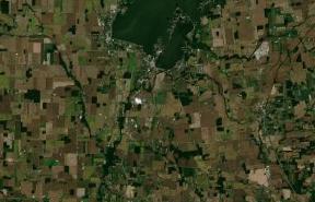
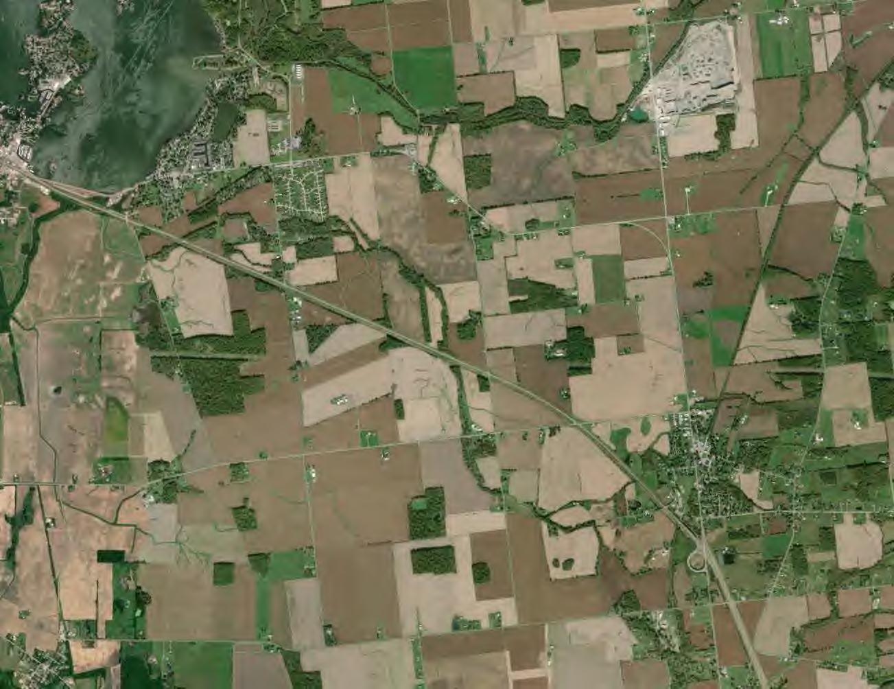
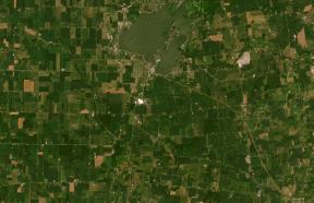
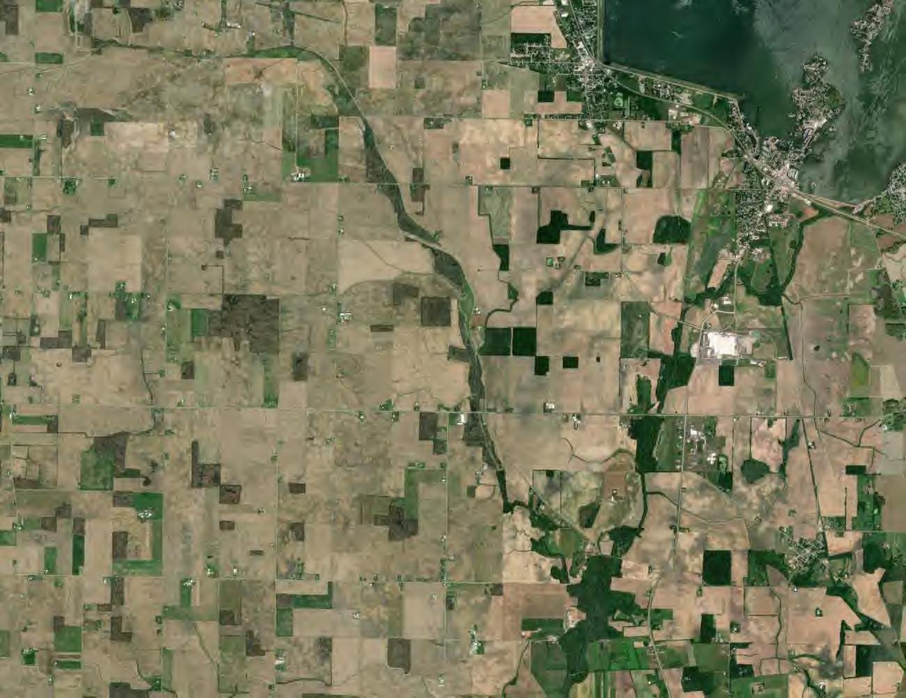
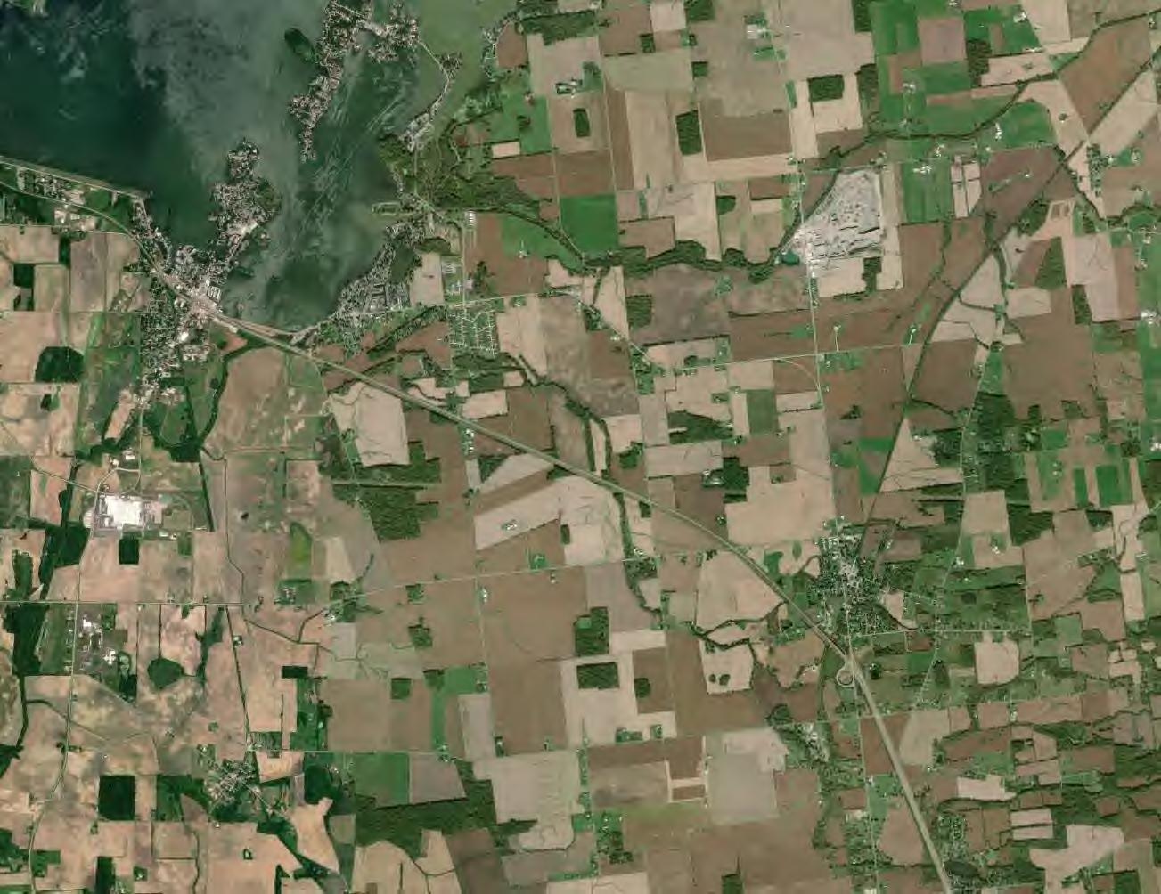
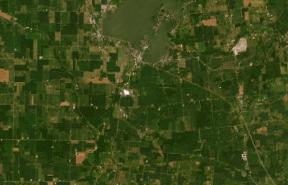
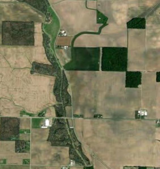
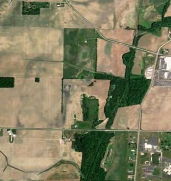
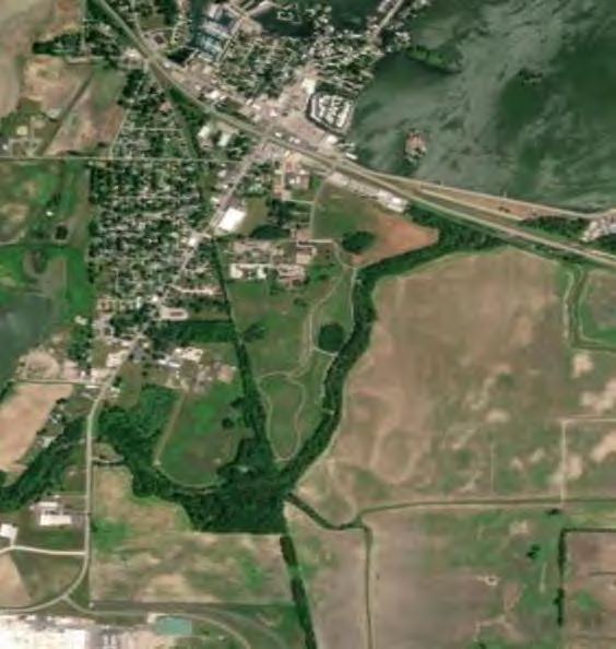
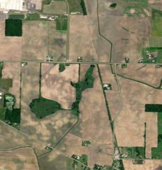
The Study Area consists of rural property located in Bloomfield, Richland, Stokes, and Washington Townships in the area adjacent to the village of Russells Point, Ohio in the northwest portion of Logan County, Ohio. The Study Area is shown on Figure 1 and subsequent figures presented in this report
The following provides a summary of the information reviewed and its applicability to the study. In addition to on-line reviews of readily available information maintained by the various agencies, Verdantas obtained comments regarding the Study Area from various departments within ODNR. Comments provided by ODNR regarding the regional geology, groundwater resources, geologic hazards, and other pertinent information are incorporated where appropriate in the sections that follow. A copy of the comment letter from ODNR is included as Appendix B. It should be noted that the comments provided by ODNR were based on the Study Area footprint at the time of the request. Due to changes in the Study Area since the time of the original request, the references to well numbers, both oil and gas or water, within the ODNR comment letter may not precisely match those provided within the following sections. The discrepancies are not considered to be substantial and do not negatively impact the ability to determine that the Facility can be developed while protecting local resources and the environment.
The Study Area is near the mapped transition between two Physiographic Provinces of Ohio; the Central Ohio Clayey Till Plain and Lake Basin/Deposits outside Huron-Erie Lake Plains, with the Study Area lying within the Central Ohio Clayey Till Plain (Ohio Division of Geologic Survey,
1998). The distinguishing characteristics of the Central Ohio Clayey Till Plain include a surface of high-lime Wisconsinan age clayey till with well-defined moraines with intervening flat-lying ground moraine and intermorainal lake basins. There are no boulder belts. There are also approximately a dozen silt-, clay- and till-filled lake basins which range from a few square miles to 200 square miles in area. The Central Ohio Clayey Till Plain contains few large streams and limited sand and gravel outwash. Elevations within this region range from approximately 700 to 1150 feet above mean seal level (msl) with moderate relief of 100 feet (Ohio Division of Geological Survey, 1998).
The surface topography within the Study Area is largely the result of the Wisconsinan-age icedeposited ground moraine and lake deposits. The moraines were deposited when the entire ice sheet receded and much of the ground-up rock material still held in the melting ice was deposited on the surface. Many glacial lakes were formed during the time that ice covered Ohio. Lake deposits are primarily very fine-grained clay and silt size sediments (Ohio Division of Geological Survey, 2005). As depicted in Figure 1, this drift varies from 20 to 260 feet in thickness across the Study Area The narrow linear patterns of thick drift in western and northern Ohio are the result of deep incisions in the underlying limestone and dolomite bedrock by a large northwest-flowing drainage system (Ohio Division of Geological Survey, 2017). Surface elevations within the Study Area, as shown on Figure 1, are approximately 1,000 to 1,050 feet above msl with an average elevation of 1,013 feet above msl (Ohio Georeferenced Information Program, 2018).
As shown in Figure 1, there are multiple Silurian aged bedrock units including the Tymotchee (St), Greenfield (Sg) and Lockport (Sl) Dolomites These units consist of thin to massive beds of carbonaceous shale that are gray and brown in color (Ohio Division of Geological Survey, 2006). Bedrock topographic surface is also depicted in Figure 1. Bedrock in the region is highly variable in elevation. The top of bedrock occurs at a low of approximately 740 feet msl in the extreme southwestern portion of the Study Area to a high of approximately 1,020 feet msl in the extreme northeastern portion of the Study Area. ODNR water well logs obtained from the 11 wells located within the footprint of the Study Area (included as Appendix C) indicate bedrock was encountered in five of the wells at depths between 85 and 143 feet below ground surface (bgs) Additional water wells located within one mile of the Study Area indicate that bedrock was encountered at depths ranging from 4 to 284 feet bgs. Information for depth to bedrock shown on the GroundWater Resources of Logan County (Schmidt, 1983) indicates that bedrock was encountered at depths between 15 and 189 feet bgs in the Study Area. Based on all of the available resources, it appears that shallow bedrock, i.e. < 10 feet bgs, is isolated to the extreme eastern portion of the Study Area and should not negatively impact the constructability of the Facility.
Information obtained from ODNR, Division of Geological Survey, Ohio Geology Interactive Map web app, was reviewed for karst topography within or near the Study Area. Based upon this information, there are no verified or suspect karst areas identified within the Study Area. The nearest mapped karst features are located approximately 0.9 mile east and south of the eastern extent of the Study Area. Due to the thickness of the clay rich drift in the majority of the Study Area and the composition of the underlying bedrock, carbonaceous shale, karst development is unlikely.
Structural features (e.g. faults, folds) and earthquake epicenters within the Study Area are shown in Figure 2. A review of the geologic and seismic information indicated that no historical earthquake epicenters are located within the Study Area The nearest seismic event occurred in
1994 and included a magnitude 2.9 earthquake located in Logan County, Ohio, with an epicenter located approximately 2 miles southwest of the Study Area (ODNR Web, 2024d)
There is a fault mapped within the southern portion of the Study Area. This is noted as an Unnamed fault along Consortium for Continental Reflection Profiling (COCORP) seismic lines. The mapped fault is Precambrian in age with a contour elevation of approximately 3,000 feet below msl. This would indicate that the mapped Precambrian fault is approximately 4,000 feet below the surface.
The design of the Facility will follow the Ohio Building Code (OBC), which includes provisions for earthquake design data. Based on the proposed construction of the Facility with subsurface components installed to a total depth of 6 to 10 feet and the collection lines typically trenched to a depth of only 3 to 4 feet below ground surface, a seismic event poses a minimal hazard/risk to the constructability and operation of the Project
The Study Area covers numerous watersheds in the Upper Great Miami Subbasin in northwest Ohio. The major watersheds in the Study Area include Muchinippi Creek, Cherokee Mans Run, Rennick Creek, and Jordan Creek. Figure 3 includes information regarding the location of FEMAmapped 100-year floodplains in the Study Area. A 100-year floodplain is an area where the occurrence of an extreme hydrologic event resulting in a flood is expected at a 100-year recurrence interval (i.e., a flood of that magnitude has a 1 percent probability of exceedance in a given year). As shown in Figure 3, portions of the Study Area along Muchinippi Creek in the west, as well as portions along the Great Miami River and Cherokee Mans Creek to the south and southeast of Indian Lake, in the central portion of the Study Area are in the mapped 100-year flood zone. The northeastern portion of the Study Area (east of Indian Lake) also is in the 100year flood zone of the South Fork Miami River. A portion of the Study Area located along the Great Miami River directly south of Indian Lake is also shown to be located in a regulatory floodway. None of the proposed Facility will be constructed within the limits of the regulatory floodway.
Verdantas completed a surface water delineation of the Study Area Surface waters and wetland features delineated in the Study Area are depicted in Figure 4. Verdantas delineated the streams and wetlands in the Study Area Surface water flow is generally towards the Great Miami River in the central portion of the Study Area. Refer to the surface water delineation report, provided under separate cover, for additional information pertaining to wetlands and waterbodies.
As depicted in Figure 5, information obtained from the ODNR Ohio Geology Interactive Map indicates there are numerous unconsolidated aquifers in the vicinity of the Study Area. The primary localized unconsolidated groundwater aquifers include the Jackson Center Complex Aquifer, the Bokengehalas Complex Aquifer, the Bellefontaine Complex Aquifer, and the Miami River Buried Valley Aquifer. The yields are reported to range from 5 to 100 gallons per minute (gpm) According to the Ground-Water Resources of Logan County, the principal aquifers in the Study Area are the limestone bedrock and the glacial deposits of sand, silt, clay, and gravel. Wells installed from 120 to 285 feet bgs in the limestone are reported to yield up to 500 gpm following development. Wells installed at depths of approximately 100 feet in the unconsolidated glacial deposits in the buried valleys also are reported to yield up to 500 gpm following development.
The ODNR Division of Geological Survey (Appendix B) reviewed impacts on public and private water supplies within the Study Area. Groundwater vulnerability ratings in the Study Area are reported to range from 114-164 out of 226 with the highest ratings being in the portions of the Study Area located closest to Indian Lake; this identifies as a moderate to high susceptibility rating. However, the ODNR Division of Geological Survey also indicated that construction of the Facility is unlikely to present a substantial risk of groundwater contamination.
The Ohio Water Well Interactive Database indicates that there are over 600 water wells located within a 1-mile radius of the Study Area. The locations of the water wells located both within the Study Area and within the 1-mile radius are shown on Figure 5. The borings completed for the wells were reported to range from 12 to over 400 feet bgs. The majority of the wells were installed within the unconsolidated sand and gravel overlying bedrock.
Based on the geocoding of water wells from ODNR, 11 wells are located within the Study Area (refer to Figure 5) Water Well Logs and Drilling Reports for 6 of the 11 wells (refer to Appendix C) indicate that the water wells were installed in sand and/or gravel at depths ranging from 28 to 117 feet bgs. The depth at which groundwater was encountered in these wells was only recorded on one of the Drilling Reports. Groundwater was reported to be encountered at a depth of 68 feet bgs in well 2058321. It is assumed from the lithology represented on the Drilling Reports for the other unconsolidated wells that groundwater was not observed until entering the sand and/or gravel unit in which the wells were installed, which was a minimum of 15 feet bgs in well 9942091. The Drilling Report for well 9946090 indicates potential artesian conditions for the well. Static groundwater levels recorded after installation of the wells ranged from 5 to 26 feet bgs, indicating that groundwater in the unconsolidated aquifers is present under confined conditions due to the overlying clay. Groundwater yields in these wells were reported to be from approximately 50 to 100 gpm (Appendix C)
The remaining five wells located within the Study Area were installed in the underlying limestone bedrock, which was encountered at depths ranging from 85 to 143 feet bgs. The water wells were installed at depths ranging from 140 to 180 feet bgs. The depth at which water was encountered was not recorded in the Drilling Reports for these five wells, however, it is assumed that it was encountered at some depth within the limestone. Static water levels after installation ranged from 3 to 30 feet bgs. Yields in these wells were reported to range from 25 to 150 gpm (Appendix C) ODNR recommends at minimum a 50-foot setback from each active well and 25 feet from plugged wells with at least 15-foot-wide access to the well
Site-specific information observed during the field evaluation is provided in the Preliminary Geotechnical Investigation Memorandum, included as Appendix A. As shown in the boring logs included in Appendix A, groundwater was initially observed during drilling at depths between 3.5 and 19 feet bgs in 17 of the 46 borings completed as part of the preliminary investigation, and at depths ranging from 2 to 16 feet in 16 of the 46 borings upon completion. Although groundwater may be encountered in soils at shallow depths in the Study Area, the groundwater aquifers providing potable water in the Study Area are encountered at depths below the anticipated depth of construction. The presence of this shallow groundwater should not present issues related to the constructability of the Facility.
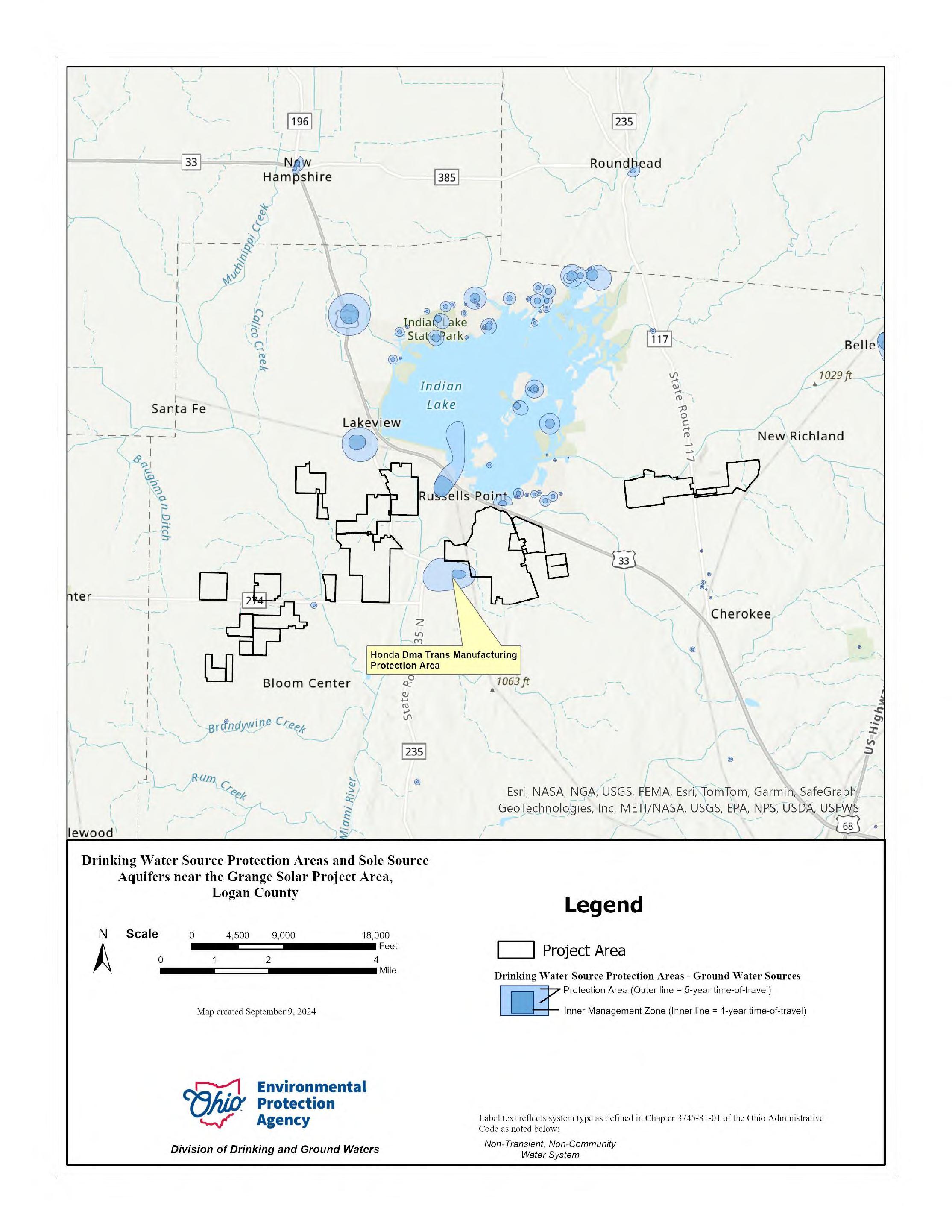
The potential presence of Source Water Protection Areas (SWPAs) for public water systems located within the Buffer Area was evaluated. SWPAs are areas defined and approved by the Ohio EPA for the purpose of protecting drinking water resources. The SWPA map provided by
Ohio EPA, Division of Drinking and Ground Waters is included as Appendix D. As shown in Appendix D and in Figure 5, the following SWPAs are located in or near the Study Area:
• Russells Point Village PWS: approximately one mile north of the Study Area;
• Honda DMA trans Manufacturing Oh Div: within the Study Area;
• Lakeview Village PWS: approximately one mile north of the Study Area;
• Whispering Valley Mhp: approximately one mile north of the Study Area; and
• La Pizzeria PWS: approximately one mile north of the Study Area; and
• Mid States Packaging, Inc: located between two portions of the southwest portion of the Study Area
Environmental regulatory programs of the Ohio EPA, as well as other regulatory agencies such as the Ohio Bureau of Underground Storage Regulations (BUSTR), have adopted regulations that restrict specific activities within SWPAs. These activities include concentrated animal feeding operations, wastewater treatment land application systems, industrial, municipal, and residual waste landfills, leaking underground storage tanks (LUSTs), and voluntary action program (VAP) cleanups. The restrictions typically apply to SWPAs relying on groundwater as their drinking water source. Construction of the proposed solar panels, along with associated infrastructure such as access roads, electrical collection lines, and a substation are not activities that would be restricted within or in the vicinity of either a surface water or groundwater SWPA. Further, sheep grazing within the Project would not be considered a concentrated animal feeding operation according to the Ohio EPA (Ohio EPA, 2015).
Based on our understanding the construction and operation of the Facility, there will be no hazardous substances and/or petroleum introduced by or emanating from the Project. Oils used within the electrical substation will be free of polychlorinated biphenyls (PCBs) and a spill control plan will be prepared if applicable. Given the proposed development (i.e., generally less than 10 feet bgs) of a solar facility, groundwater may not be encountered during construction. Therefore, it is highly unlikely that the construction and operation of the Facility will have a negative impact on public and private water supplies. The ODNR Interdepartmental Coordination Letter also notes that construction of the Facility is not anticipated to pose a significant risk to groundwater resources (Appendix B)
Soil surveys provide maps of surficial soils and general descriptions of the various soil types over the survey area and can be used to compare the suitability of large areas for general land uses. The USDA Natural Resources Conservation Service (NRCS) of Logan County (USDAWeb, 2024) maps the majority of the surficial soils within the Study Area as Latty Silty Clay (La), Fulton Silt Loam, 0 to 4 percent slope (FuA), and Blount silt loam, ground moraine, 2 to 4 percent slopes, (Blg1A1) These soil types cover approximately 33, 10, and 9.6 percent of the Study Area, respectively. The remainder of the Study Area is covered by various silt and silty clay loams as shown in Figure 6.
The soil survey information suggests that the Latty silty clay loam (La) soils have 0 to 2 percent slopes and are very poorly drained. The permeability of these soils is moderately low (0.01 to 0.06 inches/hour), and the depth to the top of the seasonal high-water table can range from 0 to 6 inches bgs. The Blount silt loam, ground moraine (Blg1A1) soils have 0 to 4 percent slopes and are somewhat poorly drained. The permeability of these soils is considered low to moderately high (0.01 to 0.20 inches/hour), and the depth to the top of the seasonal high-water table can range from 6 to 12 inches bgs. The Fulton silt loam, 0 to 4 percent slopes (FuA) soils are somewhat poorly drained. The permeability of these soils is considered low to moderately high
(0.01 to 0.20 inches/hour), and the depth to the top of the seasonal high-water table can range from 6 to 18 inches bgs (USDA Web, 2024). As noted in Section 4.5, although groundwater may be encountered at relatively shallow depths in the soils in the Study Area, this shallow groundwater is not being developed as a potable resource and should not present issues regarding constructability of structures or other features of the Facility.
Based on the Soil Survey, only one soil type within the Study Area, St. Clair silt loam (ScC2) is listed as having slopes greater than 12%. This soil type is described as having slopes between 12 to 18 percent and comprises approximately 0.2% of the total Study Area. Verdantas reviewed the USDA NRCS on-line Field Technical Guide for Logan County, Ohio for information regarding the presence of highly erodible land (HEL) in the Study Area. The information provided was reportedly prepared in the 1960s and has not been updated since that time. A few of the soil unit map symbols and soil type names have reportedly been changed since the list was first produced and a direct correlation between all current soil types in the Study Area with those on the HEL list could not be completed. However, for those soil units that do not appear to have changed, only the St. Clair silt loam, 12 to 18 percent slopes (ScD2) is listed as HEL (NRCS, 1990). As noted previously, this soil type reportedly comprises only 0.2% of the total Study Area.
According to oil, gas, and mining information included in the comment letter from ODNR in Appendix B, there are approximately 40 oil and/or gas well records located both in the Study Area and within one mile of the Study Area. There are five oil and/or gas well records that appear to be located within the Study Area. Table 1 lists the well number, map symbol (refer to Figure 5), and status of each oil and gas well in the Study Area.
Table 1. Oil and Gas Well Heads Located Within the Study Area.
34091600130000
34091600140000
34091200820000
and Abandoned
There is one known oil well located within the Study Area, as well as two gas wells, and one well of unknown purpose. There is also one well that is known to be plugged and abandoned. A structure should not be constructed over a plugged well for maintenance and safety reasons. Care should be taken to identify and avoid all active and formerly active wells in the Study Area.
Based on the geocoding of active Class II injection wells from ODNR, there are no Class II injection wells within the immediate vicinity of the Study Area (Appendix C)
ODNR recommends at minimum a 50-foot setback from each active well and 25 feet from plugged wells with at least 15-foot-wide access to the well
Information obtained from the ODNR Division of Mineral Resources (ODNR, Web, 2024c) indicates that there are no mapped abandoned underground or surface mines in the Study Area. The nearest active mine to the Study Area is the Duff Quarry, adjacent to the north of the easternmost region of the Study Area. Duff Quarry also operates several other gravel pits along the Great Miami River near the center but outside of the Study Area. Figure 7 illustrates that no known coal, underground, abandoned, or surface mines are mapped within the Study Area.
Verdantas completed a reconnaissance of the Study Area between April 29 and May 9, 2024, during completion of the drilling program for the preliminary geotechnical investigation. In addition to the site-specific observations made during the drilling activities, the remainder of the Study Area was viewed from the public right-of-way to observe general conditions including topography, surface geologic features, and surface water conditions. The Study Area contains a predominance of active agricultural fields, some forested riparian corridors, and some forested woodlots. The terrain within and surrounding the Study Area is predominantly flat, consisting of only slight undulation. Based on a review of the existing topography of the Study Area and these visual observations, it is expected that the potential for rockfalls and landslides is very low due to the relative flat to slightly rolling topography of the Study Area. In addition, Verdantas did not observe sinkholes, depressions, or evidence of karst topography within the Study Area.
Preliminary characterization of the general subsurface conditions in the Study Area was undertaken with 47 soil borings and a geotechnical laboratory program which are detailed in the Preliminary Geotechnical Investigation Memorandum in Appendix A. The drilling program was completed between April 29 and May 9, 2024. The preliminary investigation provides the information required in OAC 4906-4-08(A)(5). Based upon the conditions observed during the field program, the subsurface conditions in the vicinity of the proposed photovoltaic panel areas can be described as a surficial agricultural till zone overlying the native soil. The native subsurface conditions can generally be described as moist, medium stiff to stiff lean clay soils with varying plasticity characteristics and sand fractions. Varying thickness layers of loose to dense, dry to wet sand were encountered in 13 of the panel area borings throughout the exploration depths. Refusal to the sampling equipment was encountered in the top six inches in boreholes B24-21 and B2424. Following refusal, the drilling equipment was advanced through the interval without the driller noting issue. Groundwater was observed in 16 of the borings initially during drilling at depths between 3.5 to 14.5 feet beneath the ground surface. Final groundwater measurements at the end of drilling were between 2.0 and 15.0 feet beneath the ground surface. Bedrock was not encountered.
In the vicinity of the proposed substation, the subsurface conditions can be described as moist, medium stiff to stiff lean, silty or fat clay with varying amounts of sand to the extent of the borings. In B24-24 an approximately five-foot-thick layer of loose sand was encountered between approximately 16.5 and 22 feet bgs. Groundwater was observed in two of the three substation borings during drilling between 16.5 and 19 feet with a final measured water level between 12 and 16 feet at the end of the drilling. Auger refusal on possible bedrock was encountered at 40 feet in B24-24.
Verdantas contacted the ODOT District 7 and Logan County Engineer’s Offices to inquire about their knowledge and experience of previous construction projects, subsurface conditions, and maintenance history within the Study Area. The Logan County Engineer’s Office responded indicating that physical files are available for bridge piling logs, but that only physical copies of these files are currently available. The Logan County Engineer’s Office did not provide any description of previous construction projects, subsurface conditions, or maintenance history within the Study Area. No response from ODOT District 7 has been received at the time of this writing. If a response is received at a later date that changes the report’s conclusions, an addendum to the report will be provided.
The subsurface conditions observed in the borings were generally consistent with the geology and hydrogeology reviewed as part of the desktop study. Areas where shallow groundwater was observed or located near low lying mapped flood-prone areas may be susceptible to seasonal shallow groundwater or inundation conditions. Groundwater levels in the Study Area may be affected by seasonal and annual variations in precipitation and may be impacted by local and regional development.
Based on our review of the data and the subsurface conditions observed during the field program, Verdantas concludes that the Study Area is generally suitable for development of a solar project. In general, the development of utility scale solar project involves limited earthwork, which typically occurs during installation of access roads, collection lines, inverters, the substation, and spot grading. Based on the subsurface conditions, earthwork including grading and compaction may be accomplished utilizing typical large scale earthwork equipment. Bedrock excavation is not anticipated to be required during grading activities or panel installation.
Relatively shallow mapped and observed groundwater should be considered, where present, when selecting the racking system along and when designing final site grades and utilities. The fields currently have natural surface drainage along with drain tile that extend through or along the perimeter of the parcels. During final design and construction of the Facility, Verdantas recommends that these natural drainage paths be maintained, or enhanced, to the extent feasible by minimizing grading in these areas, aligning access roads to avoid these swales, and/or including other design features to preserve the drainage conditions in the Study Area.
It is anticipated that driven steel piles installed into a soil stratum that generally consist of medium stiff or stiffer fine-grained soils or medium dense or denser coarse-grained soils are a suitable foundation system to support the PV panels and racking systems. Conditions that would preclude driven pile installation were generally not observed within the explorations performed as part of this investigation. Shallow refusal was encountered in two locations at the site, but appears to be an isolated condition. Lightly loaded ancillary structures in the panel areas may be founded on spread footings or pad foundations bearing on suitable native soil. Temporary dewatering may be required for shallow foundations near the water table.
The subsurface conditions observed within preliminary explorations indicate that the site soils are suitable to support typical aggregate temporary construction roads along with permanent primary aggregate roads or secondary grass access roads. Depending on the construction season, subgrade stabilization may include the use of a geosynthetic material as part of the pavement section or stabilization of the roadway subgrade.
The substation will consist of various electrical infrastructure components supported on a variety of foundations. It is anticipated that some of the structures within the substation which have large loads and/or are sensitive to movement will be supported on drilled shaft foundations. Due to the deeper wet, granular soils with low fines content observed in one borings within the substation vicinity, temporary casing and drilling fluid will likely be required if drilled shafts are proposed. Based on the limited exploration, it appears feasible to utilize drilled shaft foundations at the proposed substation location. Shallow foundations are considered suitable support for electrical equipment that is relatively light with minimal lateral loading at the substation. Groundwater was observed at depths deeper than shallow foundations are typically installed.
We recommend that a design level geotechnical investigation be completed in order to optimize the design once the layout and grading plans have been finalized and the racking model is selected. The additional investigation would support final design and validate design assumptions. A design level investigation may include:
• Test piles to evaluate and optimize pile embedment, pile installation production, axial capacity, lateral capacity, and establish a pile refusal protocol for the Project. The test pile work plan should be developed based on the final racking design and foundation type. The work plan may include location, quantity, section(s), and target depth(s) of piles along with the proposed installation steps, testing documentation, loading application method(s), load steps and durations, and removal/disposal procedures
• Testing to evaluate characteristics of onsite material for handling, placement, and compaction for if specific cut or fill locations are proposed.
• Additional investigation to optimize foundation design if heavily loaded structures are proposed at the substation or elsewhere onsite.
• Additional investigation to optimize temporary or permanent access road pavement sections.
The type, quantity, and location of the additional investigation should be chosen based on the final layout of the Facility. Additional investigations should be abandoned in accordance with applicable jurisdiction requirements.
Based on the information reviewed as part of the desktop study and the conditions encountered during the field investigation, it is our opinion that the Study Area is suitable for a utility-scale solar and grazing facility from a geological, hydrogeological, and geotechnical standpoint. Based on Verdantas’ knowledge of typical solar racking construction, it does not appear that the construction of the proposed Project will have an impact on the local geology and/or hydrogeology of the Study Area. We offer the following conclusions:
• The subsurface conditions observed in the borings were generally consistent with the regional geology and hydrogeology mapping and resources reviewed as part of the desktop study. Karst geology or topography was not identified;
• Seismicity is not anticipated to significantly impact the Project;
• There are mapped 100-year floodplains located within the Study Area.
• On-site delineation of streams and wetlands located within the Study Area has been conducted.
• A portion of the Honda DMA Trans Manufacturing SWPA is located within the Study Area;
• Given the depth of water wells and oil and gas wells located in the vicinity of the Study Area and the shallow nature of the planned construction activities, it is our opinion that the construction and operation of the Facility will not impact local public and private water supplies. ODNR recommends at minimum a 50-foot setback from each active well and 25 feet from plugged wells with at least 15-foot-wide access to the well;
• There are no mapped abandoned underground or surface mines in the Study Area;
• Based on the subsurface conditions and our experience with the development of solar facilities, the soils are expected to be suitable to support typical PV panel racking foundations and substation equipment foundations. Bedrock is not expected to be encountered at typical panel foundation depths. The shallow soils are suitable for grading and compaction. The site soils are suitable to support typical aggregate temporary construction roads along with permanent primary aggregate roads or secondary grass access roads with the use of geosynthetics or stabilization based on final routing.
• Natural drainage should be maintained through construction and long-term operation of the Facility. The mapped and observed groundwater levels should be considered in the final selection of the racking system, design of grading, and design of utilities.
• Relativity shallow groundwater conditions should be considered in the grading design and the alignment of subsurface utilities; and
• A design-level geotechnical evaluation with pile load testing is recommended to inform final design. The type, quantity, and location of the additional investigation should be chosen based on the final layout of the Facility.
Verdantas has performed its services using that degree of care and skill ordinarily exercised under similar conditions by reputable members of its profession practicing in the same or similar locality at the time of service. No other warranty, expressed or implied, is made or intended by our proposal or by our oral or written reports. The work does not attempt to evaluate past or present compliance with federal, state, or local environmental or land use laws or regulations. Conclusions presented by Verdantas regarding the area within the Study Area are consistent with the Scope of Work, level of effort specified, and investigative techniques employed. Although soil quality has been inferred from the interpolation of the sampling data, you should explicitly note that subsurface conditions beyond the explorations are unknown. Reports, opinions, letters, and other documents do not evaluate the presence or absence of any condition not specifically analyzed and reported. Verdantas makes no guarantees regarding the completeness or accuracy of any information obtained from public or private files or information provided by subcontractors.
Natural Resource Conservation Service, 1990 HEL List. Retrieved August 2024, from NRCS website: Ohio | Field Office Technical Guide | NRCS - USDA
Ohio Department of Natural Resources. Interactive Water Well Database Retrieved April 2024a, from Division of Geological Survey website: https://waterwells.ohiodnr.gov/search/classicsearch/home
Ohio Department of Natural Resources, Descriptions of Geologic Map Units. Retrieved April 2024b, from Division of Geological Survey website: http://geosurvey.ohiodnr.gov/portals/geosurvey/PDFs/Misc_State_Maps&Pubs/mapunits .pdf.
Ohio Department of Natural Resources. ODNR Mines of Ohio Viewer. Retrieved April 2024c, from website: https://gis.ohiodnr.gov/MapViewer/?config=OhioMines
Ohio Department of Natural Resources. Ohio Earthquake Epicenters. Retrieved April 2024d, from Geographic Information Systems website: https://ohiodnr.gov/business-andindustry/services-to-business-industry/gis-mapping-services/earthquake-gis-mappingservice.
Ohio Department of Natural Resources. Ohio Geology Interactive Map. Retrieved April 2024e: Ohio Geology Interactive Map (ohiodnr.gov)
Ohio Division of Geological Survey, 1998, Physiographic regions of Ohio: Ohio Department of Natural Resources, Division of Geological Survey, page-size map with text, 2p., scale 1:2,100,000.
Ohio Division of Geological Survey, 2004, Shaded Drift-Thickness Map of Ohio: Ohio Department of Natural Resources, Division of Geological Survey Map SG-3, generalized page-size version with text, scale 1:2,000,000. [Revised 2017.]. Retrieved April 2024, from website: https://dam.assets.ohio.gov/image/upload/ohiodnr.gov/documents/geology/MiscMap_Oh ioShadedDriftThickness_2017.pdf
Ohio Division of Geological Survey, 2006, Bedrock Geologic Map of Ohio: Ohio Department of Natural Resources, Division of Geological Survey Map BG-1, generalized page-size version with text, 2 p., scale 1:2,000,000. Retrieved April 2024, from website: https://ohiodnr.gov/wps/wcm/connect/gov/af200770-8656-455b-b41b-ee19ef48ef45/BG1_8.5x11.pdf?MOD=AJPERES&CVID=ne.WWkh.
Ohio Division of Geological Survey, rev. 2006, Ohio Karst Areas: Ohio Department of Natural Resources, Division of Geological Survey, page-size map with text, 2p., scale 1:2,000,000.
Ohio Division of Geological Survey, 2005, Glacial Map of Ohio: Ohio Department of Natural Resources, Division of Geological Survey, page-size map with text, 2p., scale 1:2,000,000. Retrieved April 2024, from website: https://ohiodnr.gov/static/documents/geology/MiscMap_OhioGlacialMap_2005.pdf.
Geology, Hydrogeology, and Preliminary Geotechnical Report; 15770.0010
Ohio Environmental Protection Agency (Ohio EPA), 2015, CAFO NPDES Permit – General Overview of Federal Regulations. Retrieved August 2024, from website: https://dam.assets.ohio.gov/image/upload/epa.ohio.gov/Portals/35/cafo/NPDESPartI.pdf
Ohio EPA. Drinking Water Source Protection Areas – Groundwater Public Water Systems. Retrieved April 2024, from website: https://oepa.maps.arcgis.com/apps/webappviewer/index.html?id=3b39e11ba7fc43c3b41 801e3580e6d21
Ohio Georeferenced Information Program, 2018, Drift Thickness of Ohio (ODNR-DGS).Retrieved April, 2024 from website: Drift Thickness of Ohio (ODNR-DGS) | Ohio Geographically Referenced Information Program- OGRIP (arcgis.com)
Pettigrew, Mike, June 26, 2024, Interdisciplinary Review Letter, Ohio Department of Natural Resources, Office of Real Estate.
Schmidt, James J., 1983, Ground-Water Resources of Logan County, Ohio Department of Natural Resources, Division of Water.
United States Department of Agriculture, Web Soil Survey. Retrieved April 2024, from Natural Resources Conservation Service-site: https://websoilsurvey.nrcs.usda.gov/app/WebSoilSurvey.aspx
Figures
Figure 1 Bedrock Geology and Topography
Figure 2 Structural and Seismic Features
Figure 3 Floodplain Map
Figure 4 Surface Water Delineation Map
Figure 5 Aquifers and Wells
Figure 6 Soil Types
Figure 7 Underground and Surface Mines


Logan County
Unconsolidated Aquifer Inner Management Zone (Groundwater)
Source Water Protection Area (Groundwater)
Consolidated Aquifer: Devonian County Boundary
Preliminary Geotechnical Investigation

Date September17,2024
To
From VerdantasLLC
Subject PreliminaryGeotechnicalInvestigation
Project Number 18662
ThisPreliminaryGeotechnicalInvestigationMemorandumhasbeenpreparedfortheGrange SolarGrazingCenter.TheGrangeSolarGrazingCenterisacombinedutility-scalesolarenergy facilityandsheepgrazingoperationbeingdevelopedinLoganCounty,Ohio(the“Project”orthe “Facility”).ThisMemorandumisintendedtosupplementtheVerdantasGeology,Hydrogeology, andPreliminaryGeotechnicalReportpreparedtosatisfytherequirementsoftheOhioPower SittingBoard(OPSB)Rule4906-4-08(A)(5)oftheOhioAdministrativeCode.
BetweenApril29andJune14,2024,50soilboringsdesignatedB24-01toB24-50wereadvanced atthesitetodepthsrangingbetween14.9and50.0feetbeneathexistinggrade.Boringsdesigned B24-40andB24-42throughB24-44wereremovedfromthisinvestigationfollowalterationsinthe studyarea.ExplorationlocationsarepresentedastheenclosedFigure1Athrough1D.Thefield samplinglocationsandaccesswereselectedbyVerdantasourunderstandingoftheproposed constructionatthetimeofthesamplingandwereapprovedbytheclientandpropertyowners. Priortothefieldprogram,anOhio8-1-1requestwassubmittedbyourexplorationsubcontractors todelineatepublicutilitiesinthevicinityoftheexplorations.Additionally,surfaceutilityscanning withnoninvasivemethodswasperformedbyGroundPenetratingRadarSystems,LLCateachof theexplorationlocationspriortodrilling.Explorationswereadvancedinareasaccessibletothe equipmentandclearofmarkedutilities.TheboringswereinstalledbyEnvirocoreasa subcontractortoVerdantas,utilizingatrackmountedMobileB-57drillrigand2.25-inchinner diameterhollowstemaugers.Uponcompletion,boringswerebackfilledwithaugercuttings. StandardPenetrationTestingwasperformedwitha2-inchouterdiametersplitspooningeneral accordancewithASTMD1586.Bulkcompositesamplesweretakenforcorrosiontesting. Verdantasreviewedtheperformanceoftheboringsanddocumentedtheobservedconditions andtesting.SoilsampleswerereturnedtoVerdantasforfurtherreviewandlaboratorytest assignment.Atabulatedsummaryoftheboringsalongwithboringlogshavebeenenclosed.
Geotechnicallaboratorytestingwasperformedonrepresentativesoilsamples.Testingincluded moisturecontent,percentpassingNo.200sieve,particlesizedistribution,Atterberglimits,and corrosionindicatortesting(electricalresistivity,pH,sulfates,chlorides).Selecttestresultsare includedontheenclosedboringlogs.Tabulatedandindividualresultsarealsoenclosed.


B24-01Panel102015.0NotObservedNotObserved
B24-02Panel101815.09.56.0
B24-03Panel100515.013.511.0
B24-04Panel100715.014.512.5
B24-05Panel100315.0NotObservedNotObserved
B24-06Panel100515.0NotObservedNotObserved
B24-07Panel100815.0NotObservedNotObserved
B24-08Panel100014.7NotObservedNotObserved
B24-09Panel100715.0NotObservedNotObserved
B24-10Panel99615.014.012.0
B24-11Panel99715.014.06.0
B24-12Panel99415.0NotObservedNotObserved
B24-13Panel98915.09.52.5
B24-14Panel98515.0NotObservedNotObserved
B24-15Panel98415.0NotObservedNotObserved
B24-16Panel98815.0NotObservedNotObserved
B24-17Panel98315.0NotObservedNotObserved
B24-18Panel99515.0NotObservedNotObserved
B24-19Panel98815.0NotObservedNotObserved
B24-20Panel98815.09.57.0
B24-21Panel99015.0NotObservedNotObserved
B24-22Panel98815.0NotObservedNotObserved
B24-23Substation98950.016.516.0
B24-24Substation99039.919.012.0
B24-25Substation98950.0NotObservedNotObserved
B24-26Panel99115.0NotObservedNotObserved
B24-27Panel98715.0NotObservedNotObserved
B24-28Panel99115.04.03.5
B24-29Panel98915.03.53.0
B24-30Panel98616.57.03.0
B24-31Panel100915.014.514.0
B24-32Panel98315.06.52.0
B24-33Panel98815.0NotObservedNotObserved
B24-34Panel103015.0NotObservedNotObserved
B24-35Panel99515.0NotObservedNotObserved
Observed Rock NotEncountered
NotEncountered
NotEncountered
NotEncountered NotEncountered NotEncountered NotEncountered NotEncountered
NotEncountered
NotEncountered NotEncountered NotEncountered NotEncountered NotEncountered NotEncountered NotEncountered NotEncountered NotEncountered NotEncountered NotEncountered NotEncountered NotEncountered NotEncountered
NotEncountered NotEncountered NotEncountered NotEncountered NotEncountered NotEncountered NotEncountered NotEncountered NotEncountered NotEncountered NotEncountered NotEncountered
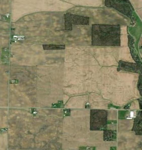
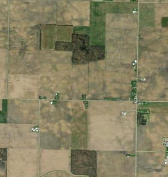
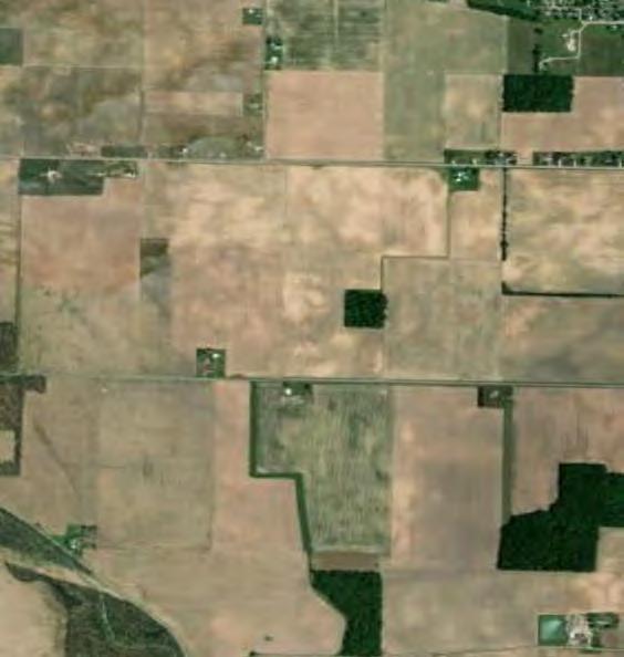
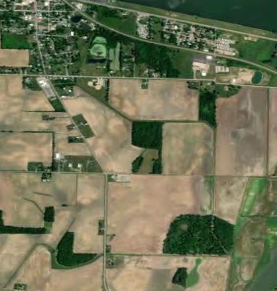
Project Area
B24-36Panel98115.0NotObservedNotObserved
B24-37Panel100415.07.5NotObserved
B24-38Panel102615.0NotObservedNotObserved
B24-39Panel103115.0NotObservedNotObserved
B24-40
ParcelOmitedfromProject
B24-41Panel103415.0NotObservedNotObserved
B24-42
B24-43
B24-44
NotEncountered
NotEncountered
NotEncountered
NotEncountered
NotEncountered
ParcelsOmitedfromProject
B24-45Panel102815.011.0NotObserved
B24-46Panel103215.0NotObserved15.0
B24-47Panel104415.0NotObservedNotObserved
B24-48Panel105815.0NotObservedNotObserved
B24-49Panel104815.0NotObservedNotObserved
B24-50Panel104315.05.52.0
[1] Surface elevation estimated from Lidar available through Ohio Statewide Imagery Program
NotEncountered
NotEncountered
NotEncountered
NotEncountered
NotEncountered
NotEncountered

PreliminaryGeotechnicalInvestigation GrangeSolarGrazingCenter LucasCounty,Ohio ProjectNo.18662
DateStarted
DateCompleted Loggedby Weather
Driller/Agency
TOPSOIL(±3inches)
:May7,2024 :May7,2024 :AVC :Cloudy60-75°F :Trey/Envirocore
BrownLeanCLAY,tracefinesand(dry)
GrayLeanCLAY,tracefinesand(dry)
GrayLeanCLAY,somefinesand,tracegravel(moist)
NOTES:
1.Testboringterminatedat±15.0feetbelowexistinggroundsurface(b.e.g.s).
2.Groundwaternotencounteredduringdrilling.
3.Boreholebackfilledwithsoilcuttingsuponcompletion.
4.SurfaceelevationestimatedfromLidaravailablethroughOhioStatewideImagery Program
DrillingEquipment
DrillingMethods
SurfaceElevation
Latitude
Longitude
(Page1of1) :Track-mountedMobileB57 :2.25-inchIDHSA :1020feet :40.44254°(WGS-84) :-83.9793°(WGS-84)
PreliminaryGeotechnicalInvestigation GrangeSolarGrazingCenter LucasCounty,Ohio ProjectNo.18662
DateStarted
DateCompleted
Loggedby
Weather
Driller/Agency
TOPSOIL(±3inches)
:May7,2024 :May7,2024 :AVC :Cloudy60-75°F :Trey/Envirocore
DuringDrilling
DrillingEquipment
DrillingMethods
SurfaceElevation Latitude Longitude
(Page1of1)
AtCompletion :Track-mountedMobileB57 :2.25-inchIDHSA :1018feet :40.41905°(WGS-84) :-83.9782°(WGS-84)
BrownLeanCLAY,tracefinesand(dry)
GraySILT,somefinesand(wet)(LiquidLimit=NP; PlasticityIndex=NP) GrayLeanCLAY,tracefinesand(wet)
NOTES:
1.Testboringterminatedat±15.0feetbelowexistinggroundsurface(b.e.g.s).
2.Groundwaterobservedat±9.5feetb.e.g.s.duringdrilling.
3.Groundwaterobservedat±6.0feetb.e.g.s.atcompletionofdrilling.
4.Boreholebackfilledwithsoilcuttingsuponcompletion.
5.SurfaceelevationestimatedfromLidaravailablethroughOhioStatewideImagery
Program
PreliminaryGeotechnicalInvestigation GrangeSolarGrazingCenter LucasCounty,Ohio ProjectNo.18662
DateStarted
DateCompleted Loggedby
Weather
Driller/Agency
TOPSOIL(±3inches)
:May7,2024 :May7,2024 :AVC :Cloudy60-75°F :Trey/Envirocore
DuringDrilling
(Page1of1)
DrillingEquipment
DrillingMethods SurfaceElevation
AtCompletion :Track-mountedMobileB57 :2.25-inchIDHSA :1005feet :40.44488°(WGS-84) :-83.9604°(WGS-84)
BrownLeanCLAY,littlefinesand,littlegravel(dry)(Liquid Limit=29;PlasticityIndex=13)
BrownLeanCLAY,littlefinesand,littlegravel(dry)
NOTES:
1.Testboringterminatedat±15.0feetbelowexistinggroundsurface(b.e.g.s).
2.Groundwaterobservedat±13.5feetb.e.g.s.duringdrilling.
3.Groundwaterobservedat±11.0feetb.e.g.s.atcompletionofdrilling.
4.Boreholebackfilledwithsoilcuttingsuponcompletion.
5.SurfaceelevationestimatedfromLidaravailablethroughOhioStatewideImagery
Program
PreliminaryGeotechnicalInvestigation
GrangeSolarGrazingCenter LucasCounty,Ohio ProjectNo.18662
DateStarted
DateCompleted
Loggedby
Weather
Driller/Agency
TOPSOIL(±3inches)
DuringDrilling
DrillingEquipment
DrillingMethods
SurfaceElevation
Latitude
Longitude
(Page1of1)
AtCompletion :Track-mountedMobileB57 :2.25-inchIDHSA :1007feet :40.44147°(WGS-84) :-83.9605°(WGS-84)
BrownLeanCLAY,tracefinesand(dry)
GrayLeanCLAY,tracefinesand(dry)
GrayLeanCLAY,tracefinesand(wet)
NOTES:
1.Testboringterminatedat±15.0feetbelowexistinggroundsurface(b.e.g.s).
2.Groundwaterobservedat±14.5feetb.e.g.s.duringdrilling.
3.Groundwaterobservedat±12.5feetb.e.g.s.atcompletionofdrilling.
4.Boreholebackfilledwithsoilcuttingsuponcompletion.
5.SurfaceelevationestimatedfromLidaravailablethroughOhioStatewideImagery Program
PreliminaryGeotechnicalInvestigation GrangeSolarGrazingCenter LucasCounty,Ohio ProjectNo.18662
DateStarted
DateCompleted Loggedby
Weather
Driller/Agency
TOPSOIL(±3inches)
BrownLeanCLAY,littlefinesand(dry)(LiquidLimit=33; PlasticityIndex=16)
BrownLeanCLAY,tracefinesand(moist)
BrownLeanCLAY,tracefinesand(moist)
BrownLeanCLAY,tracefinesand(moist)
BrownLeanCLAY,somefinesand(dry)
NOTES:
1.Testboringterminatedat±15.0feetbelowexistinggroundsurface(b.e.g.s).
2.Groundwaternotencounteredduringdrilling.
3.Boreholebackfilledwithsoilcuttingsuponcompletion.
4.SurfaceelevationestimatedfromLidaravailablethroughOhioStatewideImagery Program
DrillingEquipment
DrillingMethods
SurfaceElevation
Latitude
Longitude
(Page1of1) :Track-mountedMobileB57 :2.25-inchIDHSA
-83.9629°(WGS-84)
PreliminaryGeotechnicalInvestigation GrangeSolarGrazingCenter LucasCounty,Ohio ProjectNo.18662
DateStarted DateCompleted Loggedby
Weather
Driller/Agency
TOPSOIL(±3inches)
:May9,2024 :May9,2024 :AVC :Cloudy55-70°F :Trey/Envirocore
BrownLeanCLAY,littlefinesand(moist)
GrayLeanCLAY,littlefinesand(dry)(LiquidLimit=35; PlasticityIndex=17)
BrownLeanCLAY,littlefinesand(moist)
NOTES:
1.Testboringterminatedat±15.0feetbelowexistinggroundsurface(b.e.g.s).
2.Groundwaternotencounteredduringdrilling.
3.Boreholebackfilledwithsoilcuttingsuponcompletion.
4.SurfaceelevationestimatedfromLidaravailablethroughOhioStatewideImagery Program
DrillingEquipment
DrillingMethods
SurfaceElevation
Latitude
Longitude
(Page1of1) :Track-mountedMobileB57 :2.25-inchIDHSA :1005feet :40.43498°(WGS-84) :-83.9528°(WGS-84)
PreliminaryGeotechnicalInvestigation
GrangeSolarGrazingCenter LucasCounty,Ohio ProjectNo.18662
DateStarted
DateCompleted Loggedby Weather
Driller/Agency
TOPSOIL(±3inches)
BrownLeanCLAYandfineSAND(dry)
DrillingEquipment
DrillingMethods
SurfaceElevation
Latitude
Longitude
(Page1of1) :Track-mountedMobileB57 :2.25-inchIDHSA :1008feet :40.43063°(WGS-84) :-83.9674°(WGS-84)
BrownLeanCLAYandfineSAND(dry)
GrayLeanCLAYandfineSAND(dry)
GrayLeanCLAYandfineSAND(dry)
GrayLeanCLAYandfineSAND(dry)
NOTES:
1.Testboringterminatedat±15.0feetbelowexistinggroundsurface(b.e.g.s).
2.Groundwaternotencounteredduringdrilling.
3.Boreholebackfilledwithsoilcuttingsuponcompletion.
4.SurfaceelevationestimatedfromLidaravailablethroughOhioStatewideImagery Program
PreliminaryGeotechnicalInvestigation GrangeSolarGrazingCenter LucasCounty,Ohio ProjectNo.18662
DateStarted
DateCompleted Loggedby Weather
Driller/Agency
TOPSOIL(±3inches)
:May7,2024 :May7,2024 :AVC :Cloudy60-75°F :Trey/Envirocore
BrownLeanCLAY,littlefinesand(dry)
GrayLeanCLAY,somefinesand(dry) GrayLeanCLAY,somefinesand(dry)
NOTES:
1.Testboringterminatedat±14.7feetbelowexistinggroundsurface(b.e.g.s).
2.Groundwaternotencounteredduringdrilling.
3.Boreholebackfilledwithsoilcuttingsuponcompletion.
4.SurfaceelevationestimatedfromLidaravailablethroughOhioStatewideImagery Program
DrillingEquipment
DrillingMethods
SurfaceElevation
Latitude
Longitude
(Page1of1) :Track-mountedMobileB57 :2.25-inchIDHSA :1000feet :40.43061°(WGS-84) :-83.9579°(WGS-84)
PreliminaryGeotechnicalInvestigation GrangeSolarGrazingCenter LucasCounty,Ohio ProjectNo.18662
DateStarted
DateCompleted Loggedby
Weather
Driller/Agency
TOPSOIL(±3inches)
BrownLeanCLAY,somefinesand(dry)
DrillingEquipment
DrillingMethods
SurfaceElevation
Latitude
Longitude
(Page1of1) :Track-mountedMobileB57 :2.25-inchIDHSA :1007feet :40.42714°(WGS-84) :-83.9631°(WGS-84)
BrownLeanCLAY,somefinesand(dry)
BrownLeanCLAY,somefinesand(dry)
GrayLeanCLAY,somefinesand(dry)(LiquidLimit=31; PlasticityIndex=15) GrayLeanCLAY,littlegravel(dry)
NOTES:
1.Testboringterminatedat±15.0feetbelowexistinggroundsurface(b.e.g.s).
2.Groundwaternotencounteredduringdrilling.
3.Boreholebackfilledwithsoilcuttingsuponcompletion.
4.SurfaceelevationestimatedfromLidaravailablethroughOhioStatewideImagery Program
PreliminaryGeotechnicalInvestigation GrangeSolarGrazingCenter LucasCounty,Ohio ProjectNo.18662
DateStarted
DateCompleted
Loggedby
Weather
Driller/Agency
TOPSOIL(±3inches)
BrownfineSAND,somesilt(dry)
:May1,2024 :May1,2024 :AVC :M.Cloudy55-80°F :Trey/Envirocore
DuringDrilling
(Page1of1)
DrillingEquipment
DrillingMethods
SurfaceElevation
AtCompletion :Track-mountedMobileB57 :2.25-inchIDHSA :996feet :40.47306°(WGS-84) :-83.946°(WGS-84)
BrownLeanCLAY,tracefinesand(dry)
GrayLeanCLAY,somefinesand(dry)
GrayfinetomediumSAND,littleclay(wet)
NOTES:
1.Testboringterminatedat±15.0feetbelowexistinggroundsurface(b.e.g.s).
2.Groundwaterobservedat±14.0feetb.e.g.s.duringdrilling.
3.Groundwaterobservedat±12.0feetb.e.g.s.atcompletionofdrilling.
4.Boreholebackfilledwithsoilcuttingsuponcompletion.
5.SurfaceelevationestimatedfromLidaravailablethroughOhioStatewideImagery
Program
PreliminaryGeotechnicalInvestigation GrangeSolarGrazingCenter LucasCounty,Ohio ProjectNo.18662
DateStarted
DateCompleted Loggedby Weather
Driller/Agency
:May1,2024 :May1,2024 :AVC :M.Cloudy55-80°F :Trey/Envirocore
DuringDrilling
(Page1of1)
DrillingEquipment
DrillingMethods
SurfaceElevation
Latitude
Longitude
AtCompletion :Track-mountedMobileB57 :2.25-inchIDHSA :997feet :40.46994°(WGS-84) :-83.946°(WGS-84)
NOTES:
1.Testboringterminatedat±15.0feetbelowexistinggroundsurface(b.e.g.s).
2.Groundwaterobservedat±14.0feetb.e.g.s.duringdrilling.
3.Groundwaterobservedat±6.0feetb.e.g.s.atcompletionofdrilling.
4.Boreholebackfilledwithsoilcuttingsuponcompletion.
5.SurfaceelevationestimatedfromLidaravailablethroughOhioStatewideImagery
Program
PreliminaryGeotechnicalInvestigation
GrangeSolarGrazingCenter LucasCounty,Ohio ProjectNo.18662
DateStarted DateCompleted Loggedby Weather
Driller/Agency
TOPSOIL(±3inches)
:May1,2024 :May1,2024 :AVC :M.Cloudy55-80°F :Trey/Envirocore
BrownLeanCLAY,littlefinesand,littlegravel(dry)(Liquid Limit=29;PlasticityIndex=15)
BrownLeanCLAY,somefinesand(dry)
GrayLeanCLAY,tracefinesand(dry)
BrownLeanCLAY,somefinesand(dry)
NOTES:
1.Testboringterminatedat±15.0feetbelowexistinggroundsurface(b.e.g.s).
2.Groundwaternotencounteredduringdrilling.
3.Boreholebackfilledwithsoilcuttingsuponcompletion.
4.SurfaceelevationestimatedfromLidaravailablethroughOhioStatewideImagery Program
DrillingEquipment
DrillingMethods
SurfaceElevation Latitude Longitude
(Page1of1) :Track-mountedMobileB57 :2.25-inchIDHSA :994feet :40.46319°(WGS-84) :-83.9423°(WGS-84)
PreliminaryGeotechnicalInvestigation GrangeSolarGrazingCenter LucasCounty,Ohio ProjectNo.18662
DateStarted
DateCompleted Loggedby
Weather
TOPSOIL(±3inches)
DuringDrilling
DrillingEquipment
DrillingMethods
SurfaceElevation
Latitude
Longitude
(Page1of1)
AtCompletion :Track-mountedMobileB57 :2.25-inchIDHSA :989feet :40.44284°(WGS-84) :-83.938°(WGS-84)
BrownLeanCLAYandfineSAND(moist)
BrownfineSAND,somesilt(moist)(LiquidLimit=NP; PlasticityIndex=NP)
BrownfineSAND,somesilt(moist)
BrowncoarseSAND,somesilt(wet) BrownfineSANDandSILT(moist)
GrayLeanCLAY,littlefinesand(dry)
NOTES:
1.Testboringterminatedat±15.0feetbelowexistinggroundsurface(b.e.g.s).
2.Groundwaterobservedat±9.5feetb.e.g.s.duringdrilling.
3.Groundwaterobservedat±2.5feetb.e.g.s.atcompletionofdrilling.
4.Boreholebackfilledwithsoilcuttingsuponcompletion.
5.SurfaceelevationestimatedfromLidaravailablethroughOhioStatewideImagery
Program
PreliminaryGeotechnicalInvestigation GrangeSolarGrazingCenter LucasCounty,Ohio ProjectNo.18662
DateStarted
DateCompleted Loggedby
Weather
Driller/Agency
TOPSOIL(±3inches)
BrownLeanCLAY,tracefinesand(dry)
DrillingEquipment
DrillingMethods
SurfaceElevation
Latitude
Longitude
(Page1of1) :Track-mountedMobileB57 :2.25-inchIDHSA :985feet :40.47282°(WGS-84) :-83.9122°(WGS-84)
BrownLeanCLAY,tracefinesand(dry)
GrayHighPlasticityCLAY(dry)(LiquidLimit=51;Plasticity Index=29)
GrayLeanCLAY,tracefinesand(dry)
GrayLeanCLAY,tracefinesand(dry)
NOTES:
1.Testboringterminatedat±15.0feetbelowexistinggroundsurface(b.e.g.s).
2.Groundwaternotencounteredduringdrilling.
3.Boreholebackfilledwithsoilcuttingsuponcompletion.
4.SurfaceelevationestimatedfromLidaravailablethroughOhioStatewideImagery Program
PreliminaryGeotechnicalInvestigation
GrangeSolarGrazingCenter LucasCounty,Ohio ProjectNo.18662
DateStarted
DateCompleted
Loggedby
Weather
Driller/Agency
TOPSOIL(±3inches) BrownLeanCLAY(dry)
:May9,2024 :May9,2024 :AVC :Cloudy55-70°F :Trey/Envirocore
NOTES:
1.Testboringterminatedat±15.0feetbelowexistinggroundsurface(b.e.g.s).
2.Groundwaternotencounteredduringdrilling.
3.Boreholebackfilledwithsoilcuttingsuponcompletion.
4.SurfaceelevationestimatedfromLidaravailablethroughOhioStatewideImagery Program
DrillingEquipment
DrillingMethods
SurfaceElevation
Latitude
Longitude
(Page1of1) :Track-mountedMobileB57 :2.25-inchIDHSA :984feet :40.47068°(WGS-84) :-83.9088°(WGS-84)
PreliminaryGeotechnicalInvestigation GrangeSolarGrazingCenter LucasCounty,Ohio ProjectNo.18662
DateStarted
DateCompleted Loggedby
Weather
Driller/Agency
TOPSOIL(±3inches)
GrayLeanCLAY,tracefinesand(dry)
GrayLeanCLAY,tracefinesand(dry)(LiquidLimit=53; PlasticityIndex=30)
GrayLeanCLAY,tracefinesand(dry)
GrayLeanCLAY,tracefinesand(dry)
NOTES:
1.Testboringterminatedat±15.0feetbelowexistinggroundsurface(b.e.g.s).
2.Groundwaternotencounteredduringdrilling.
3.Boreholebackfilledwithsoilcuttingsuponcompletion.
4.SurfaceelevationestimatedfromLidaravailablethroughOhioStatewideImagery Program
DrillingEquipment
DrillingMethods
SurfaceElevation
Latitude
Longitude
(Page1of1) :Track-mountedMobileB57 :2.25-inchIDHSA :988feet :40.46824°(WGS-84) :-83.9149°(WGS-84)
PreliminaryGeotechnicalInvestigation GrangeSolarGrazingCenter LucasCounty,Ohio ProjectNo.18662
DateStarted
DateCompleted Loggedby
Weather
Driller/Agency
TOPSOIL(±3inches)
LightbrownLeanCLAY,somefinesand(dry) LightbrownLeanCLAY,somefinesand(dry)
DrillingEquipment
DrillingMethods
SurfaceElevation
Latitude Longitude
(Page1of1) :Track-mountedMobileB57 :2.25-inchIDHSA :983feet :40.46566°(WGS-84) :-83.9122°(WGS-84)
BrownLeanCLAY,somefinesand(dry) GrayLeanCLAY,tracefinesand(dry) GrayLeanCLAY,tracefinesand(dry)
NOTES:
1.Testboringterminatedat±15.0feetbelowexistinggroundsurface(b.e.g.s).
2.Groundwaternotencounteredduringdrilling.
3.Boreholebackfilledwithsoilcuttingsuponcompletion.
4.SurfaceelevationestimatedfromLidaravailablethroughOhioStatewideImagery Program
PreliminaryGeotechnicalInvestigation GrangeSolarGrazingCenter LucasCounty,Ohio ProjectNo.18662
DateStarted DateCompleted
Driller/Agency
:May1,2024 :May1,2024 :AVC :M.Cloudy55-80°F :Trey/Envirocore
NOTES:
1.Testboringterminatedat±15.0feetbelowexistinggroundsurface(b.e.g.s).
2.Groundwaternotencounteredduringdrilling.
3.Boreholebackfilledwithsoilcuttingsuponcompletion.
4.SurfaceelevationestimatedfromLidaravailablethroughOhioStatewideImagery Program
DrillingEquipment
DrillingMethods
SurfaceElevation
Latitude
Longitude
(Page1of1) :Track-mountedMobileB57 :2.25-inchIDHSA :995feet :40.46749°(WGS-84) :-83.9246°(WGS-84)
PreliminaryGeotechnicalInvestigation GrangeSolarGrazingCenter LucasCounty,Ohio ProjectNo.18662
DateStarted DateCompleted
Driller/Agency
:May1,2024 :May1,2024 :AVC :M.Cloudy55-80°F :Trey/Envirocore
NOTES:
1.Testboringterminatedat±15.0feetbelowexistinggroundsurface(b.e.g.s).
2.Groundwaternotencounteredduringdrilling.
3.Boreholebackfilledwithsoilcuttingsuponcompletion.
4.SurfaceelevationestimatedfromLidaravailablethroughOhioStatewideImagery Program
DrillingEquipment
DrillingMethods
SurfaceElevation
Latitude
Longitude
(Page1of1) :Track-mountedMobileB57 :2.25-inchIDHSA :988feet :40.46358°(WGS-84) :-83.9244°(WGS-84)
PreliminaryGeotechnicalInvestigation GrangeSolarGrazingCenter
LucasCounty,Ohio ProjectNo.18662
DateStarted
DateCompleted Loggedby
Weather
Driller/Agency
TOPSOIL(±12inches)
:April29,2024 :April29,2024 :AVC :M.Cloudy60-80°F :Trey/Envirocore
DuringDrilling
(Page1of1)
DrillingEquipment
DrillingMethods
SurfaceElevation
Latitude
Longitude
AtCompletion :Track-mountedMobileB57 :2.25-inchIDHSA :988feet :40.45731°(WGS-84) :-83.9262°(WGS-84)
BrownLeanCLAY,somefinesand(dry)
GrayLeanCLAY,littlegravel(moist)
Gray,brownLeanCLAY,littlefinesand(dry)
GrayLeanCLAY,tracefinesand(wet)
NOTES:
1.Testboringterminatedat±15.0feetbelowexistinggroundsurface(b.e.g.s).
2.Groundwaterobservedat±9.5feetb.e.g.s.duringdrilling.
3.Groundwaterobservedat±7.0feetb.e.g.s.atcompletionofdrilling.
4.Boreholebackfilledwithsoilcuttingsuponcompletion.
5.SurfaceelevationestimatedfromLidaravailablethroughOhioStatewideImagery
Program
PreliminaryGeotechnicalInvestigation GrangeSolarGrazingCenter
LucasCounty,Ohio ProjectNo.18662
DateStarted
DateCompleted Loggedby Weather
Driller/Agency
TOPSOIL(±3inches)
:April29,2024
:April29,2024
:AVC :M.Cloudy60-80°F :Trey/Envirocore
BrownLeanCLAY,tracefinesand(dry)
BrownLeanCLAYandfineSAND(dry)
GrayLeanCLAY,littlegravel(moist) GrayLeanCLAY,somefinesand(moist)
NOTES:
1.Testboringterminatedat±15.0feetbelowexistinggroundsurface(b.e.g.s).
2.Groundwaternotencounteredduringdrilling.
3.Boreholebackfilledwithsoilcuttingsuponcompletion.
4.SurfaceelevationestimatedfromLidaravailablethroughOhioStatewideImagery Program
DrillingEquipment
DrillingMethods
SurfaceElevation
(Page1of1) :Track-mountedMobileB57 :2.25-inchIDHSA :990feet :40.45527°(WGS-84) :-83.9306°(WGS-84)
PreliminaryGeotechnicalInvestigation
GrangeSolarGrazingCenter LucasCounty,Ohio ProjectNo.18662
DateStarted
DateCompleted Loggedby
Weather
Driller/Agency
TOPSOIL(±3inches)
:April30,2024 :April30,2024 :AVC :M.Cloudy60-75°F :Trey/Envirocore
BrownFatCLAY,tracefinesand(dry)
BrownFatCLAY,tracefinesand(dry)(LiquidLimit=51; PlasticityIndex=28)
GrayLeanCLAY,tracefinesand(dry)
GrayLeanCLAY,tracefinesand(dry)
NOTES:
1.Testboringterminatedat±15.0feetbelowexistinggroundsurface(b.e.g.s).
2.Groundwaternotencounteredduringdrilling.
3.Boreholebackfilledwithsoilcuttingsuponcompletion.
4.SurfaceelevationestimatedfromLidaravailablethroughOhioStatewideImagery Program
DrillingEquipment
DrillingMethods
SurfaceElevation
(Page1of1) :Track-mountedMobileB57 :2.25-inchIDHSA :988feet :40.45544°(WGS-84) :-83.9191°(WGS-84)
PreliminaryGeotechnicalInvestigation GrangeSolarGrazingCenter LucasCounty,Ohio ProjectNo.18662
DateStarted
DateCompleted Loggedby
Weather
Driller/Agency
TOPSOIL(±3inches)
DrillingEquipment
DrillingMethods
SurfaceElevation
Latitude
Longitude
DuringDrilling
AtCompletion
BrownHighPlasticityCLAY(dry)(LiquidLimit=53; PlasticityIndex=30)
BrowntolightbrownLeanCLAY,somefinesand(dry)
NOTES:
1.Testboringterminatedat±50.0feetbelowexistinggroundsurface(b.e.g.s)
2.Groundwaterobservedat±16.5feetb.e.g.s.duringdrilling.
3.Groundwaterobservedat±16.0feetb.e.g.s.atcompletionofdrilling.
4.Boreholebackfilledwithsoilcuttingsuponcompletion.
5.SurfaceelevationestimatedfromLidaravailablethroughOhioStatewideImagery Program
(Page1of3)
PreliminaryGeotechnicalInvestigation GrangeSolarGrazingCenter LucasCounty,Ohio ProjectNo.18662
DateStarted
DateCompleted Loggedby
Weather
Driller/Agency
:April29,2024 :April29,2024 :AVC :M.Cloudy60-80°F :Trey/Envirocore
DuringDrilling
(Page2of3)
DrillingEquipment
DrillingMethods
SurfaceElevation
Latitude
Longitude
AtCompletion :Track-mountedMobileB57 :2.25-inchIDHSA :989feet :40.45467°(WGS-84) :-83.9238°(WGS-84)
BrownLeanCLAY,somefinesand(dry)(LiquidLimit=27; PlasticityIndex=12)
NoRecovery
NOTES:
1.Testboringterminatedat±50.0feetbelowexistinggroundsurface(b.e.g.s)
2.Groundwaterobservedat±16.5feetb.e.g.s.duringdrilling.
3.Groundwaterobservedat±16.0feetb.e.g.s.atcompletionofdrilling.
4.Boreholebackfilledwithsoilcuttingsuponcompletion.
5.SurfaceelevationestimatedfromLidaravailablethroughOhioStatewideImagery
Program
PreliminaryGeotechnicalInvestigation
GrangeSolarGrazingCenter
LucasCounty,Ohio ProjectNo.18662
DateStarted
DateCompleted
Loggedby
Weather
Driller/Agency
:April29,2024 :April29,2024 :AVC :M.Cloudy60-80°F :Trey/Envirocore
DuringDrilling
(Page3of3)
DrillingEquipment
DrillingMethods
SurfaceElevation
Latitude
Longitude
AtCompletion :Track-mountedMobileB57 :2.25-inchIDHSA :989feet :40.45467°(WGS-84) :-83.9238°(WGS-84)
GrayLeanCLAY,tracefinetomediumsand,tracegravel (moist)
GrayLeanCLAY,tracefinetomediumsand,tracegravel (moist)
NOTES:
1.Testboringterminatedat±50.0feetbelowexistinggroundsurface(b.e.g.s)
2.Groundwaterobservedat±16.5feetb.e.g.s.duringdrilling.
3.Groundwaterobservedat±16.0feetb.e.g.s.atcompletionofdrilling.
4.Boreholebackfilledwithsoilcuttingsuponcompletion.
5.SurfaceelevationestimatedfromLidaravailablethroughOhioStatewideImagery
Program
PreliminaryGeotechnicalInvestigation
GrangeSolarGrazingCenter LucasCounty,Ohio ProjectNo.18662
DateStarted DateCompleted Loggedby Weather
Driller/Agency
TOPSOIL(±3inches)
DuringDrilling
DrillingEquipment
DrillingMethods
SurfaceElevation
(Page1of2)
AtCompletion :Track-mountedMobileB57 :2.25-inchIDHSA :990feet :40.4526°(WGS-84) :-83.9244°(WGS-84)
LightbrownHighPlasticityCLAY,tracefinesand(dry) (LiquidLimit=60;PlasticityIndex=36)
BrownLean,tracefinesandCLAY(dry)
BrownLean,tracefinesandCLAY(dry) GrayfineSANDandGRAVEL(wet)
NOTES:
1.Testboringterminatedat±40.0feetbelowexistinggroundsurface(b.e.g.s)at augerrefusal.
2.Groundwaterobservedat±19.0feetb.e.g.s.duringdrilling.
3.Groundwaterobservedat±12.0feetb.e.g.s.atcompletionofdrilling.
4.Boreholebackfilledwithsoilcuttingsuponcompletion.
5.SurfaceelevationestimatedfromLidaravailablethroughOhioStatewideImagery Program
PreliminaryGeotechnicalInvestigation
GrangeSolarGrazingCenter LucasCounty,Ohio ProjectNo.18662
DateStarted
Driller/Agency
:April29,2024 :April29,2024 :AVC :M.Cloudy60-80°F :Trey/Envirocore
DuringDrilling
GrayLeanCLAY,littlegravel(wet)
NOTES:
(Page2of2)
DrillingEquipment
AtCompletion :Track-mountedMobileB57 :2.25-inchIDHSA :990feet :40.4526°(WGS-84) :-83.9244°(WGS-84)
GrayLeanCLAY,somefinetocoarsesand,tracegravel (wet)
GrayLeanCLAY,somefinetocoarsesand,tracegravel (wet)
GrayLeanCLAY,somefinetocoarsesand,tracegravel (wet)
1.Testboringterminatedat±40.0feetbelowexistinggroundsurface(b.e.g.s)at augerrefusal.
2.Groundwaterobservedat±19.0feetb.e.g.s.duringdrilling.
3.Groundwaterobservedat±12.0feetb.e.g.s.atcompletionofdrilling.
4.Boreholebackfilledwithsoilcuttingsuponcompletion.
5.SurfaceelevationestimatedfromLidaravailablethroughOhioStatewideImagery Program
PreliminaryGeotechnicalInvestigation GrangeSolarGrazingCenter LucasCounty,Ohio ProjectNo.18662
NOTES:
DateStarted DateCompleted Loggedby Weather
Driller/Agency
TOPSOIL(±3inches)
BrownLeanCLAY(dry)
BrownLeanCLAY(dry)
BrownLeanCLAY(dry) GrayfineSAND(wet)
Brown,grayLeanSILTYCLAY,littlefinesand(dry)(Liquid Limit=21;PlasticityIndex=7)
1.Testboringterminatedat±50.0feetbelowexistinggroundsurface(b.e.g.s).
2.Groundwaternotencounteredduringdrilling.
3.Boreholebackfilledwithsoilcuttingsuponcompletion.
4.SurfaceelevationestimatedfromLidaravailablethroughOhioStatewideImagery Program
DrillingEquipment
DrillingMethods
SurfaceElevation
Latitude
Longitude
(Page1of3) :Track-mountedMobileB57 :2.25-inchIDHSA :989feet :40.4526°(WGS-84) :-83.9214°(WGS-84)
PreliminaryGeotechnicalInvestigation
GrangeSolarGrazingCenter LucasCounty,Ohio ProjectNo.18662
DateStarted
DateCompleted Loggedby
Weather
Driller/Agency
:April30,2024 :April30,2024 :AVC :M.Cloudy60-75°F :Trey/Envirocore
Brown,grayLeanSILTYCLAY,littlefinesand(dry)
Brown,grayLeanSILTYCLAY,littlefinesand(dry)
NOTES:
1.Testboringterminatedat±50.0feetbelowexistinggroundsurface(b.e.g.s).
2.Groundwaternotencounteredduringdrilling.
3.Boreholebackfilledwithsoilcuttingsuponcompletion.
4.SurfaceelevationestimatedfromLidaravailablethroughOhioStatewideImagery Program
DrillingEquipment
DrillingMethods
SurfaceElevation
Latitude
Longitude
(Page2of3) :Track-mountedMobileB57 :2.25-inchIDHSA :989feet :40.4526°(WGS-84) :-83.9214°(WGS-84)
PreliminaryGeotechnicalInvestigation
GrangeSolarGrazingCenter LucasCounty,Ohio ProjectNo.18662
DateStarted DateCompleted Loggedby Weather
Driller/Agency
DrillingEquipment
DrillingMethods
SurfaceElevation
Latitude
Longitude
(Page3of3)
NOTES:
1.Testboringterminatedat±50.0feetbelowexistinggroundsurface(b.e.g.s).
2.Groundwaternotencounteredduringdrilling.
3.Boreholebackfilledwithsoilcuttingsuponcompletion.
4.SurfaceelevationestimatedfromLidaravailablethroughOhioStatewideImagery Program
PreliminaryGeotechnicalInvestigation GrangeSolarGrazingCenter LucasCounty,Ohio ProjectNo.18662
DateStarted
DateCompleted
Loggedby
Weather
Driller/Agency
TOPSOIL(±3inches)
:April30,2024 :April30,2024 :AVC :M.Cloudy60-75°F :Trey/Envirocore
GrayLeanCLAY,tracefinesand(dry) GrayLeanCLAY,tracefinesand(dry)
NOTES:
1.Testboringterminatedat±15.0feetbelowexistinggroundsurface(b.e.g.s).
2.Groundwaternotencounteredduringdrilling.
3.Boreholebackfilledwithsoilcuttingsuponcompletion.
4.SurfaceelevationestimatedfromLidaravailablethroughOhioStatewideImagery Program
DrillingEquipment
DrillingMethods
SurfaceElevation
Latitude
Longitude
(Page1of1) :Track-mountedMobileB57 :2.25-inchIDHSA :991feet :40.44834°(WGS-84) :-83.9286°(WGS-84)
PreliminaryGeotechnicalInvestigation
GrangeSolarGrazingCenter LucasCounty,Ohio ProjectNo.18662
DateStarted
DateCompleted Loggedby Weather
Driller/Agency
TOPSOIL(±3inches)
GrayLeanCLAY,somefinesand(moist)
DrillingEquipment
(Page1of1) :Track-mountedMobileB57 :2.25-inchIDHSA :987feet :40.44819°(WGS-84) :-83.9204°(WGS-84)
GrayLeanCLAY,somefinesand(moist)
GrayLeanCLAY,somefinesand(moist)
GrayLeanCLAY,somefinesand(moist)
NOTES:
1.Testboringterminatedat±15.0feetbelowexistinggroundsurface(b.e.g.s).
2.Groundwaternotencounteredduringdrilling.
3.Boreholebackfilledwithsoilcuttingsuponcompletion.
4.SurfaceelevationestimatedfromLidaravailablethroughOhioStatewideImagery Program
PreliminaryGeotechnicalInvestigation GrangeSolarGrazingCenter LucasCounty,Ohio ProjectNo.18662
DateStarted
DateCompleted Loggedby
Weather
Driller/Agency
DuringDrilling
AtCompletion
DrillingEquipment
DrillingMethods
SurfaceElevation
Latitude
Longitude
TOPSOIL(±3inches)
BrownLeanCLAY,somefinesand(dry)(LiquidLimit=32; PlasticityIndex=15)
BrownLeanCLAY,tracefinesand(wet)
GrayLeanCLAY,tracegravel(dry)
GrayLeanCLAY,tracegravel(dry)
NOTES:
1.Testboringterminatedat±15.0feetbelowexistinggroundsurface(b.e.g.s).
2.Groundwaterobservedat±4.0feetb.e.g.s.duringdrilling.
3.Groundwaterobservedat±3.5feetb.e.g.s.atcompletionofdrilling.
4.Boreholebackfilledwithsoilcuttingsuponcompletion.
5.SurfaceelevationestimatedfromLidaravailablethroughOhioStatewideImagery Program
(Page1of1)
-83.926°(WGS-84)
PreliminaryGeotechnicalInvestigation GrangeSolarGrazingCenter LucasCounty,Ohio ProjectNo.18662
DateStarted
Driller/Agency
TOPSOIL(±3inches)
DuringDrilling
DrillingEquipment
DrillingMethods
(Page1of1)
AtCompletion :Track-mountedMobileB57 :2.25-inchIDHSA :989feet :40.44234°(WGS-84) :-83.9195°(WGS-84)
BrownLeanCLAY,somefinesand(dry)
GraycoarseSAND,littlegravel(wet)
GrayCLAY,littlegravel(dry)
NOTES:
1.Testboringterminatedat±15.0feetbelowexistinggroundsurface(b.e.g.s).
2.Groundwaterobservedat±3.5feetb.e.g.s.duringdrilling.
3.Groundwaterobservedat±3.0feetb.e.g.s.atcompletionofdrilling.
4.Boreholebackfilledwithsoilcuttingsuponcompletion.
5.SurfaceelevationestimatedfromLidaravailablethroughOhioStatewideImagery
Program
PreliminaryGeotechnicalInvestigation GrangeSolarGrazingCenter LucasCounty,Ohio ProjectNo.18662
DateStarted DateCompleted Loggedby
TOPSOIL(±3inches)
DuringDrilling
DrillingEquipment
DrillingMethods
SurfaceElevation
Latitude Longitude
(Page1of1)
AtCompletion :Track-mountedMobileB57 :2.25-inchIDHSA :986feet :40.46197°(WGS-84) :-83.8831°(WGS-84)
BrownLeanCLAY,tracegravel(moist)
BrownfinetocoarseSAND,someclay(moist)
BrowntograyfinetocoarseSAND(wet) GraySILT(wet)
GrayLeanCLAY,tracefinesand(moist)(LiquidLimit=26; PlasticityIndex=8)
NOTES:
1.Testboringterminatedat±15.0feetbelowexistinggroundsurface(b.e.g.s).
2.Groundwaterobservedat±7.0feetb.e.g.s.duringdrilling.
3.Groundwaterobservedat±3.0feetb.e.g.s.atcompletionofdrilling.
4.Boreholebackfilledwithsoilcuttingsuponcompletion.
5.SurfaceelevationestimatedfromLidaravailablethroughOhioStatewideImagery
Program
PreliminaryGeotechnicalInvestigation GrangeSolarGrazingCenter LucasCounty,Ohio ProjectNo.18662
DateStarted DateCompleted Loggedby
Weather
Driller/Agency
TOPSOIL(±3inches)
DrillingEquipment
DrillingMethods
SurfaceElevation
Latitude
Longitude
(Page1of1)
AtCompletion :Track-mountedMobileB57 :2.25-inchIDHSA :1009feet :40.45944°(WGS-84) :-83.8679°(WGS-84)
BrownLeanCLAY,tracefinesand(moist)
BrownLeanCLAY,somefinesand(dry)
BrownLeanCLAY,somefinesand(dry)
BrownLeanCLAY,somefinesand(dry)(LiquidLimit=35; PlasticityIndex=17)
BrownLeanCLAY,somefinesand(dry)
1.Testboringterminatedat±15.0feetbelowexistinggroundsurface(b.e.g.s).
2.Groundwaterobservedat±14.5feetb.e.g.s.duringdrilling.
3.Groundwaterobservedat±14.0feetb.e.g.s.atcompletionofdrilling.
4.Boreholebackfilledwithsoilcuttingsuponcompletion.
5.SurfaceelevationestimatedfromLidaravailablethroughOhioStatewideImagery
Program
PreliminaryGeotechnicalInvestigation GrangeSolarGrazingCenter LucasCounty,Ohio ProjectNo.18662
DateStarted
TOPSOIL(±3inches)
DuringDrilling
DrillingEquipment
DrillingMethods
SurfaceElevation
Latitude
Longitude
(Page1of1)
AtCompletion :Track-mountedMobileB57 :2.25-inchIDHSA :983feet :40.45509°(WGS-84) :-83.8857°(WGS-84)
BrownHighPlasticityCLAY,littlefinesand(moist)(Liquid Limit=50;PlasticityIndex=29)
BrownHighPlasticityCLAY,littlefinesand(moist)
GrayfineSANDandSILT(wet)
GrayfineSANDandSILT(wet)
NOTES:
1.Testboringterminatedat±15.0feetbelowexistinggroundsurface(b.e.g.s).
2.Groundwaterobservedat±6.5feetb.e.g.s.duringdrilling.
3.Groundwaterobservedat±2.0feetb.e.g.s.atcompletionofdrilling.
4.Boreholebackfilledwithsoilcuttingsuponcompletion.
5.SurfaceelevationestimatedfromLidaravailablethroughOhioStatewideImagery
Program
PreliminaryGeotechnicalInvestigation GrangeSolarGrazingCenter LucasCounty,Ohio ProjectNo.18662
DateStarted
DateCompleted Loggedby
Weather
Driller/Agency
TOPSOIL(±3inches)
BrowntograyLeanCLAY,tracegravel(moist)
GrayLeanCLAY,tracefinesand(moist)
GrayfineSANDandLeanCLAY,tracegravel(moist)
GrayfineSANDandLeanCLAY,tracegravel(moist)
GrayfineSANDandLeanCLAY,tracegravel(moist)
NOTES:
1.Testboringterminatedat±15.0feetbelowexistinggroundsurface(b.e.g.s).
2.Groundwaternotencounteredduringdrilling.
3.Boreholebackfilledwithsoilcuttingsuponcompletion.
4.SurfaceelevationestimatedfromLidaravailablethroughOhioStatewideImagery Program
DrillingEquipment
DrillingMethods
SurfaceElevation
Latitude
Longitude
(Page1of1) :Track-mountedMobileB57 :2.25-inchIDHSA :988feet :40.457°(WGS-84) :-83.8772°(WGS-84)
PreliminaryGeotechnicalInvestigation GrangeSolarGrazingCenter LucasCounty,Ohio ProjectNo.18662
DateStarted
DateCompleted Loggedby
Weather
Driller/Agency
TOPSOIL(±3inches)
BrownLeanCLAY(moist)
BrownLeanCLAY,somefinesand(dry)
DrillingEquipment
DrillingMethods
SurfaceElevation
Latitude
Longitude
(Page1of1) :Track-mountedMobileB57 :2.25-inchIDHSA
-83.8663°(WGS-84)
BrownLeanCLAY,somefinesand(dry)
BrownLeanCLAY,somefinesand(dry)
BrownLeanCLAY,somefinesand(dry)
NOTES:
1.Testboringterminatedat±15.0feetbelowexistinggroundsurface(b.e.g.s).
2.Groundwaternotencounteredduringdrilling.
3.Boreholebackfilledwithsoilcuttingsuponcompletion.
4.SurfaceelevationestimatedfromLidaravailablethroughOhioStatewideImagery Program
PreliminaryGeotechnicalInvestigation GrangeSolarGrazingCenter LucasCounty,Ohio ProjectNo.18662
DateStarted DateCompleted Loggedby Weather
Driller/Agency
(Page1of1) :Track-mountedMobileB57 :2.25-inchIDHSA :995feet :40.45117°(WGS-84) :-83.8942°(WGS-84) NOTES:
TOPSOIL(±3inches)
BrownLeanCLAY,littlefinesand(wet)
BrownfineSAND,littleclay(dry)
BrownfineSAND,littleclay(dry)
BrownLeanCLAY,somefinesand,littlegravel(dry)
GrayLeanCLAY,somefinesand(dry)
1.Testboringterminatedat±15.0feetbelowexistinggroundsurface(b.e.g.s).
2.Groundwaternotencounteredduringdrilling.
3.Boreholebackfilledwithsoilcuttingsuponcompletion.
4.SurfaceelevationestimatedfromLidaravailablethroughOhioStatewideImagery Program
DrillingEquipment
DrillingMethods
SurfaceElevation
Latitude
Longitude
PreliminaryGeotechnicalInvestigation
GrangeSolarGrazingCenter LucasCounty,Ohio ProjectNo.18662
DateStarted
DateCompleted Loggedby
Weather
Driller/Agency
TOPSOIL(±3inches)
BrownLeanCLAY(moist)
:May2,2024 :May2,2024 :AVC :M.Sunny60-85°F :Trey/Envirocore
GrayLeanCLAY(moist)
GrayLeanCLAY,somefinesand(moist)
GrayLeanCLAY,somefinesand(moist)
GrayLeanCLAY,somefinesand(moist)
NOTES:
1.Testboringterminatedat±15.0feetbelowexistinggroundsurface(b.e.g.s).
2.Groundwaternotencounteredduringdrilling.
3.Boreholebackfilledwithsoilcuttingsuponcompletion.
4.SurfaceelevationestimatedfromLidaravailablethroughOhioStatewideImagery Program
DrillingEquipment
DrillingMethods
SurfaceElevation
Latitude
Longitude
(Page1of1) :Track-mountedMobileB57 :2.25-inchIDHSA :981feet :40.44983°(WGS-84) :-83.8843°(WGS-84)
PreliminaryGeotechnicalInvestigation
GrangeSolarGrazingCenter LucasCounty,Ohio ProjectNo.18662
DateStarted
DateCompleted Loggedby Weather
Driller/Agency
TOPSOIL(±3inches)
GrayHighPlasticityCLAY(dry)(LiquidLimit=62;Plasticity Index=41)
DarkgrayLeanCLAY,tracefinesand(dry)
GrayLeanCLAY,somefinesand(wet)
GrayLeanCLAY,tracefinesand(dry)
(Page1of1)
DrillingEquipment
DrillingMethods
SurfaceElevation
Latitude
Longitude
:40.44937°(WGS-84) :-83.8748°(WGS-84) NOTES:
1.Testboringterminatedat±15.0feetbelowexistinggroundsurface(b.e.g.s).
2.Groundwaterobservedat±7.5feetb.e.g.s.duringdrilling.
3.Boreholebackfilledwithsoilcuttingsuponcompletion.
4.SurfaceelevationestimatedfromLidaravailablethroughOhioStatewideImagery Program
PreliminaryGeotechnicalInvestigation GrangeSolarGrazingCenter LucasCounty,Ohio ProjectNo.18662
DateStarted DateCompleted Loggedby Weather
Driller/Agency
TOPSOIL(±3inches)
BrownLeanCLAY,tracefinesand(moist)
DrillingEquipment
DrillingMethods
SurfaceElevation
Latitude
Longitude
(Page1of1) :Track-mountedMobileB57 :2.25-inchIDHSA :1026feet :40.44371°(WGS-84) :-83.8772°(WGS-84)
BrownLeanCLAY,somefinesand(dry)
BrownLeanCLAY,somefinesand(dry)
Brown,grayLeanCLAY,littlegravel(dry)
Brown,grayLeanCLAY,littlegravel(dry)
NOTES:
1.Testboringterminatedat±15.0feetbelowexistinggroundsurface(b.e.g.s).
2.Groundwaternotencounteredduringdrilling.
3.Boreholebackfilledwithsoilcuttingsuponcompletion.
4.SurfaceelevationestimatedfromLidaravailablethroughOhioStatewideImagery Program
PreliminaryGeotechnicalInvestigation GrangeSolarGrazingCenter LucasCounty,Ohio ProjectNo.18662
DateStarted DateCompleted Loggedby Weather
Driller/Agency
TOPSOIL(±3inches)
BrownLeanCLAY,littlefinesand(dry)
DrillingEquipment
DrillingMethods
SurfaceElevation
Latitude
Longitude
(Page1of1) :Track-mountedMobileB57 :2.25-inchIDHSA :1031feet :40.44395°(WGS-84) :-83.8693°(WGS-84)
Brown,grayLeanCLAY,somefinesand,tracegravel(dry)
Brown,grayLeanCLAY,somefinesand,tracegravel(dry) (LiquidLimit=33;PlasticityIndex=17)
Brown,grayLeanCLAY,somefinesand,tracegravel(dry)
1.Testboringterminatedat±15.0feetbelowexistinggroundsurface(b.e.g.s).
2.Groundwaternotencounteredduringdrilling.
3.Boreholebackfilledwithsoilcuttingsuponcompletion.
4.SurfaceelevationestimatedfromLidaravailablethroughOhioStatewideImagery Program
PreliminaryGeotechnicalInvestigation GrangeSolarGrazingCenter LucasCounty,Ohio ProjectNo.18662
DateStarted
DateCompleted Loggedby
Weather
Driller/Agency
TOPSOIL(±3inches)
BrownLeanCLAY,somefinesand(moist)(Liquid Limit=34;PlasticityIndex=18)
DrillingEquipment
DrillingMethods
SurfaceElevation
Latitude
Longitude
(Page1of1) :Track-mountedMobileB57 :2.25-inchIDHSA
-83.8571°(WGS-84)
BrownLeanCLAY,somefinesand(moist)
BrownLeanCLAY,somefinesand(moist)
BrownLeanCLAY,somefinesand(moist)
BrownLeanCLAY,somefinesand(moist)
NOTES:
1.Testboringterminatedat±15.0feetbelowexistinggroundsurface(b.e.g.s).
2.Groundwaternotencounteredduringdrilling.
3.Boreholebackfilledwithsoilcuttingsuponcompletion.
4.SurfaceelevationestimatedfromLidaravailablethroughOhioStatewideImagery Program
PreliminaryGeotechnicalInvestigation GrangeSolarGrazingCenter LucasCounty,Ohio ProjectNo.18662
DateStarted
DateCompleted Loggedby
Weather
Driller/Agency
TOPSOIL(±3inches)
:May2,2024 :May2,2024 :AVC :M.Sunny60-85°F :Trey/Envirocore
Gray,brownLeanCLAY,littlefinesand(dry)
GrayLeanCLAY,littlefinesand(dry)
BrownLeanCLAY,somefinesand(dry)(LiquidLimit=35; PlasticityIndex=17)
GrayLeanCLAY,littlefinesand(moist)
NOTES:
1.Testboringterminatedat±15.0feetbelowexistinggroundsurface(b.e.g.s).
2.Groundwaterobservedat±11.0feetb.e.g.s.duringdrilling.
3.Boreholebackfilledwithsoilcuttingsuponcompletion.
4.SurfaceelevationestimatedfromLidaravailablethroughOhioStatewideImagery Program
DrillingEquipment
DrillingMethods
SurfaceElevation
(Page1of1)
:Track-mountedMobileB57 :2.25-inchIDHSA :1028feet :40.46887°(WGS-84) :-83.8305°(WGS-84)
PreliminaryGeotechnicalInvestigation GrangeSolarGrazingCenter LucasCounty,Ohio ProjectNo.18662
DateStarted DateCompleted Loggedby Weather
Driller/Agency
TOPSOIL(±3inches)
:May2,2024 :May2,2024 :AVC :M.Sunny60-85°F :Trey/Envirocore
(Page1of1)
DrillingEquipment
AtCompletion :Track-mountedMobileB57 :2.25-inchIDHSA :1032feet :40.46985°(WGS-84) :-83.8231°(WGS-84)
BrownLeanCLAYandfineSAND(dry)
BrownLeanCLAYandfineSAND(dry)
BrownLeanCLAYandfineSAND(dry)
BrownLeanCLAYandfineSAND(dry)
BrownLeanCLAYandfineSAND(dry)
NOTES:
1.Testboringterminatedat±15.0feetbelowexistinggroundsurface(b.e.g.s).
2.Groundwaterobservedat±15.0feetb.e.g.s.atcompletionofdrilling.
3.Boreholebackfilledwithsoilcuttingsuponcompletion.
4.SurfaceelevationestimatedfromLidaravailablethroughOhioStatewideImagery Program
DrillingMethods
SurfaceElevation Latitude Longitude
PreliminaryGeotechnicalInvestigation GrangeSolarGrazingCenter LucasCounty,Ohio ProjectNo.18662
DateStarted
DateCompleted Loggedby
Weather
Driller/Agency
TOPSOIL(±3inches)
BrownLeanCLAY,somefinesand(dry)
DrillingEquipment
DrillingMethods
SurfaceElevation
Latitude
Longitude
(Page1of1) :Track-mountedMobileB57 :2.25-inchIDHSA
-83.8151°(WGS-84)
BrownLeanCLAY,somefinesand(dry)(LiquidLimit=37; PlasticityIndex=19)
BrownLeanCLAY,somefinesand(dry)
BrownLeanCLAY,somefinesand(dry)
NOTES:
1.Testboringterminatedat±15.0feetbelowexistinggroundsurface(b.e.g.s).
2.Groundwaternotencounteredduringdrilling.
3.Boreholebackfilledwithsoilcuttingsuponcompletion.
4.SurfaceelevationestimatedfromLidaravailablethroughOhioStatewideImagery Program
PreliminaryGeotechnicalInvestigation GrangeSolarGrazingCenter LucasCounty,Ohio ProjectNo.18662
DateStarted DateCompleted Loggedby Weather
Driller/Agency
TOPSOIL(±3inches)
:May2,2024 :May2,2024 :AVC :M.Sunny60-85°F :Trey/Envirocore
BrownLeanCLAY,somefinesand(dry)
BrownLeanCLAY,somefinesand(dry)(LiquidLimit=31; PlasticityIndex=15)
BrownLeanCLAY,somefinesand(dry)
NOTES:
1.Testboringterminatedat±15.0feetbelowexistinggroundsurface(b.e.g.s).
2.Groundwaternotencounteredduringdrilling.
3.Boreholebackfilledwithsoilcuttingsuponcompletion.
4.SurfaceelevationestimatedfromLidaravailablethroughOhioStatewideImagery Program
DrillingEquipment
DrillingMethods
SurfaceElevation
Latitude
Longitude
(Page1of1) :Track-mountedMobileB57 :2.25-inchIDHSA :1058feet :40.46971°(WGS-84) :-83.805°(WGS-84)
PreliminaryGeotechnicalInvestigation
GrangeSolarGrazingCenter LucasCounty,Ohio ProjectNo.18662
DateStarted
DateCompleted Loggedby
Weather
Driller/Agency
TOPSOIL(±3inches)
:May1,2024 :May1,2024 :AVC :M.Cloudy55-80°F :Trey/Envirocore
BrownfineSAND,somesilt(dry)
GrayLeanCLAY,somefinesand,tracegravel(moist)
GrayLeanCLAY,somefinesand,tracegravel(moist)
NOTES:
1.Testboringterminatedat±15.0feetbelowexistinggroundsurface(b.e.g.s).
2.Groundwaternotencounteredduringdrilling.
3.Boreholebackfilledwithsoilcuttingsuponcompletion.
4.SurfaceelevationestimatedfromLidaravailablethroughOhioStatewideImagery Program
DrillingEquipment
DrillingMethods
SurfaceElevation
Latitude
Longitude
(Page1of1) :Track-mountedMobileB57 :2.25-inchIDHSA :1048feet :40.47248°(WGS-84) :-83.7968°(WGS-84)
PreliminaryGeotechnicalInvestigation GrangeSolarGrazingCenter LucasCounty,Ohio ProjectNo.18662
DateStarted
DateCompleted Loggedby
Weather
Driller/Agency
TOPSOIL(±3inches)
:May1,2024 :May1,2024 :AVC :M.Cloudy55-80°F :Trey/Envirocore
DuringDrilling
BrownfineSAND,somesilt(dry)
(Page1of1)
DrillingEquipment
DrillingMethods
SurfaceElevation
AtCompletion :Track-mountedMobileB57 :2.25-inchIDHSA :1043feet :40.47544°(WGS-84) :-83.7913°(WGS-84)
BrownLeanCLAYandfinetomediumSAND,tracegravel (wet)
GrayfineSANDandSILTYCLAY,tracegravel(moist)
NOTES:
1.Testboringterminatedat±15.0feetbelowexistinggroundsurface(b.e.g.s).
2.Groundwaterobservedat±5.5feetb.e.g.s.duringdrilling.
3.Groundwaterobservedat±2.0feetb.e.g.s.atcompletionofdrilling.
4.Boreholebackfilledwithsoilcuttingsuponcompletion.
5.SurfaceelevationestimatedfromLidaravailablethroughOhioStatewideImagery
Program
B24-04Composite5.0-15.0------------12007.76258.635.74-B24-09Composite5.0-15.018008.01159.517.78-B24-11Composite5.0-15.020008.0393.968.54-B24-15Composite5.0-15.015007.86142.397.34-B24-20Composite5.0-15.012007.84210.208.74-B24-24Composite5.0-15.011007.80206.326.23-B24-24Composite25.0-35.012007.73384.567.90-B24-28Composite5.0-15.014007.93155.957.66-B24-32Composite5.0-15.015007.76427.188.38-B24-38Composite5.0-15.016007.79119.149.20-B24-47Composite5.0-15.013007.76151.509.20-B24-50Composite5.0-15.011007.80179.2011.26-B24-01SPT-28.0-10.020.6----93.8------------CL B24-02SPT-28.0-10.021.8----78.0NPNP--------ML B24-03SPT-13.0-5.015.2----73.62913--------CL B24-03SPT-313.0-15.013.3----61.1------------ML B24-04SPT-28.0-10.017.8----94.4------------CL B24-05SPT-11.0-2.517.4----84.33316----`--CL B24-06SPT-28.0-10.016.5----85.33517--------CL B24-07SPT-36.0-7.012.8----55.2------------CL B24-08SPT-13.0-5.020.1----85.0------------CL B24-09SPT-11.0-2.514.4----75.3------------CL B24-09SPT-48.5-10.012.6----76.63115--------CL B24-10SPT-28.0-10.012.6----72.8------------CL B24-11SPT-313.0-15.010.27.339.653.1------------CL B24-12SPT-13.0-5.014.8----69.62915--------CL B24-13SPT-11.0-2.517.5----54.0------------CL B24-13SPT-23.5-5.018.9----21.3NPNP--------SM B24-13SPT-48.5-10.011.6----38.2------------SM B24-14SPT-11.0-2.525.9----95.9------------CL B24-14SPT-36.0-7.531.6----99.95129--------CH B24-15SPT-47.5-9.027.0----99.6------------CL B24-16SPT-23.5-5.025.3----98.85330--------CH B24-17SPT-23.5-5.014.7----75.6------------CL B24-18SPT-13.0-5.024.4----99.84826--------CL B24-19SPT-28.0-10.014.4----72.4------------CL B24-20SPT-13.5-5.017.4----73.4------------CL B24-20SPT-313.5-15.027.4----97.0------------CL B24-21SPT-10.0-0.527.4----96.5------------CL B24-21SPT-23.5-5.06.2----66.3------------CL B24-22SPT-23.0-5.024.5----98.75128--------CH B24-23SPT-13.5-5.026.6----99.35330--------CH B24-23SPT-313.5-15.018.83.532.963.7------------CL B24-23SPT-523.5-25.017.3----69.62712--------CL B24-23SPT-943.5-45.023.6----89.4------------CL B24-24SPT-13.5-5.023.9----96.76036--------CH B24-24SPT-733.5-35.015.1----70.5------------CL B24-25SPT-28.0-10.022.9----99.9------------CL B24-25SPT-418.0-20.029.4----90.2217--------CL-ML
B24-25SPT-838.0-40.024.6----98.9------------CL B24-26SPT-13.0-5.027.1----96.9------------CL B24-27SPT-10.0-0.312.5----65.1------------CL B24-27SPT-413.5-15.015.4----76.8------------CL B24-28SPT-11.0-2.514.0----72.23215--------CL B24-28SPT-23.5-5.027.20.32.697.1------------CL B24-28SPT-48.5-10.022.4----97.5------------CL B24-29SPT-13.0-5.022.1----67.5------------CL B24-30SPT-25.0-6.511.014.763.222.1------------SC B24-30SPT-410.0-11.523.7----96.1268--------CL B24-31SPT-11.0-2.515.7----77.5------------CL B24-31SPT-36.5-8.017.5----78.83517--------CL
B24-32SPT-11.0-2.527.0----84.55029--------CH
B24-32SPT-48.5-10.017.6----40.7------------SM
B24-33SPT-37.5-9.014.8----36.7------------SC
B24-34SPT-513.5-15.011.1----30.9------------SC
B24-35SPT-23.5-5.08.9----16.2------------SC
B24-36SPT-48.5-10.016.0----78.4------------CL
B24-37SPT-11.0-2.528.5----93.46241--------CH
B24-38SPT-23.5-5.013.4----76.8------------CL
B24-39SPT-36.0-7.511.9----76.63317--------CL
B24-41SPT-11.0-2.514.3----77.2------------CL
B24-41SPT-23.5-5.014.0----73.43418--------CL
B24-45SPT-28.0-10.016.1----80.13517--------CL
B24-46SPT-11.0-2.513.2----61.0------------CL
B24-46SPT-48.5-10.011.2----57.7------------CL
B24-47SPT-23.5-5.015.5----79.03719--------CL
B24-48SPT-28.0-10.013.7----67.93115--------CL
B24-49SPT-28.0-10.013.8----76.1------------CL B24-50SPT-28.0-10.011.06.636.357.1------------CL
B24-50SPT-313.0-15.08.7----42.519.06.0--------SC-SM
---Indicatestestingnotperformed

Client: Verdantas
Client Reference:Grange 18662
Project No.:2024-417-001
Lab ID:
Lab ID
Boring No. B24-05B24-06B24-07B24-08B24-09
Tare Number 41 43 6510049 Wt. of Tare & Wet Sample (g)47.3162.5051.3251.1668.43 Wt. of Tare & Dry Sample (g)40.7854.1345.8543.1660.24
Notes : Tested ByJWDate6/4/24Checked ByBRBDate6/5/24
Client: Verdantas
Client Reference:Grange 18662
Project No.:2024-417-001
Lab ID:
024025026027028
Lab ID
029030031032033
Boring No. B24-13B24-13B24-14B24-14B24-15
Tare Number 39 52 76 82 85 Wt. of Tare & Wet Sample (g)38.5737.3172.3488.5580.47 Wt. of Tare & Dry Sample (g)32.9633.7658.1068.0764.08
Notes : Tested ByJWDate6/5/24Checked ByJLKDate6/6/24
Client: Verdantas
Client Reference:Grange 18662
Project No.:2024-417-001
Lab ID: 034035036037038
Lab ID
039040041042043
Boring No. B24-20B24-21B24-21B24-22B24-23
Tare
Notes : Tested ByJWDate6/5/24Checked ByJLKDate6/6/24
Client: Verdantas
Client Reference:Grange 18662
Project No.:2024-417-001
Lab ID:
Lab ID
049050051052053
Boring No. B24-25B24-25B24-25B24-26B24-27
Tare Number 83 69 54 41 32 Wt. of Tare & Wet Sample (g)101.5361.9666.5883.6580.40 Wt. of Tare & Dry Sample (g)83.2748.6354.0766.4971.79
Notes : Tested ByJWDate6/6/24Checked ByJLKDate6/7/24
Client: Verdantas
Client Reference:Grange 18662
Project No.:2024-417-001
Lab ID:
054055056057058
Lab ID
059060061062063
Boring No. B24-30B24-30B24-31B24-31B24-32
Tare Number 67 30 99 31 90
Wt. of Tare & Wet Sample (g)44.6881.4964.0788.2955.27 Wt. of Tare & Dry Sample (g)40.5866.5055.8275.6044.22
Notes :
Tested ByJWDate6/6/24Checked ByJLKDate6/7/24
Client: Verdantas
Client Reference:Grange 18662
Project No.:2024-417-001
Lab ID: 064065066067068 Boring No.:
Lab ID
069070071072073
Boring No. B24-37B24-38B24-39B24-41B24-41
Notes : Tested ByJWDate6/7/24Checked ByKCDate6/10/24
Client: Verdantas
Client Reference:Grange 18662
Project No.:2024-417-001
Lab ID:
Boring No.:
Depth (ft):
Sample No.:
Tare Number
Wt. of Tare & Wet Sample (g)
Wt. of Tare & Dry Sample (g)
Weight of Tare (g)
Weight of Water (g)
Weight of Dry Sample (g)
Water Content (%)
Lab ID
079080081082083
Boring No. B24-45B24-46B24-46B24-47B24-48
Sample No.
Client: Verdantas
Client Reference:Grange 18662
Project No.:2024-417-001
Lab ID:
AASHTO T 291 - 94 (2018) (Method B )
Client:VerdantasBoring No.:B24-04
ClitRf G18662
Client Reference: Grange 18662
Project No.:2024-417-001
Lab ID: 2024-417-001-001
Dth(ft) 50150'
Depth (ft): 5 0-15 0'
Sample No.:Composite
Description:Gray Soil ( -# 10 Sieve material )
Notes: 1) Samples and standards were buffered by the addition of an equal volume of the 0.2 M KNO3 solution (1:1 volume). 2)Samples were dried for a minimum of 12 hours at 110 +/- 5oC.
Client:Verdantas
Client Reference:Grange 18662
Project No.:2024-417-001
AASHTO T 289-91 (2013)
Lab ID: 001
Boring No.:B24-04
Depth (ft):5.0-15.0'
Sample No.:Composite
Drying Tare No.:1601
Testing Tare No.:A
BufferMeter
4.004.01 7.007.00 10.0010.00
Tested ByJAMDate6/13/24 Checked ByJLKDate6/14/24
Client: Verdantas
Client Reference:Grange 18662
Project No.:2024-417-001
Lab ID: 2024-417-001-001
Boring No.:B24-04
Depth (ft):5.0-15.0'
Sample No.:Composite
Visual Description:Gray ( - #10 Sieve material )
Note: The ratio of Miller Box area versus distance between electrodes is equal to 1.
AASHTO T 290-95 (2020)
Client: Verdantas
Client Reference:Grange 18662
Project No.:2024-417-001
Lab ID: 2024-417-001-001
Boring No.:B24-04
Depth (ft):5.0-15.0'
Sample No.:Composite
Soil Description:Gray Soil
Sulfate Standard - Calibration Curve Spectrophotometer Readings
Sulfate Ion Concentrations (mg/L)
Spectrophotometer Readings (FAU)
UnderrangeUnderrange 7204263112163243
Measurement of Barium Chloride Turbidity
(Sample contains 5.0 mL NaCl solution and 0.3 g BaCl2 2H2O)
Sample Weight (g): 100.0
Sample Diluted: Yes
Sample Diluted to 50 ml (ml): 10
Sulfate Solution Added (ml): 0
Sample Sulfate Ion Concentration: 258.63 mg/L SO4 (ppm)
Sample Sulfate Ion Content: 775.9 mg/Kg SO4 (not corrected for moisture)
Sample Sulfate Ion Content: 784.6 mg/Kg SO4 (corrected for moisture)
AASHTO T 290-95 Calibration Curve
Tested by:JAMDate:6/13/24 Checked by:kcDate:6/17/24 page 1 of 1 DCN: CT-S87 DATE: 3/5/2020 REVISION: 1
AASHTO T 291 - 94 (2018) (Method B )
Client:VerdantasBoring No.:B24-09
ClitRf G18662
Client Reference: Grange 18662
Project No.:2024-417-001
Lab ID: 2024-417-001-002
Dth(ft) 50150'
Depth (ft): 5 0-15 0'
Sample No.:Composite
Description:Gray Soil ( -# 10 Sieve material )
Notes: 1) Samples and standards were buffered by the addition of an equal volume of the 0.2 M KNO3 solution (1:1 volume). 2)Samples were dried for a minimum of 12 hours at 110 +/- 5oC.
Client: Verdantas
Client Reference:Grange 18662
Project No.: 2024-417-001
Lab ID: 002
Boring No.: B24-09
Depth (ft): 5.0-15.0'
Sample No.: Composite
Drying Tare No.: 1609
Testing Tare No.: N
Meter Calibration (as used each day)
4.004.01 7.007.00 10.0010.00
Tested ByJAMDate6/13/24 Checked ByJLKDate6/14/24 page 1 of 1 DCN: CT-S36B DATE 6/5/14 REVISION: 1
Client: Verdantas
Client Reference:Grange 18662
Project No.:2024-417-001
Lab ID: 2024-417-001-002
Boring No.:B24-09
Depth (ft):5.0-15.0'
Sample No.:Composite
Visual Description:Gray ( - #10 Sieve material ) Tare No.:
Note: The ratio of Miller Box area versus distance between electrodes is equal to 1.
AASHTO T 290-95
Client: Verdantas
Boring No.:B24-09
Client Reference:Grange 18662 Depth (ft):5.0-15.0'
Project No.:2024-417-001
Lab ID: 2024-417-001-002
Sample No.:Composite
Soil Description:Gray Soil
Sulfate Standard - Calibration Curve Spectrophotometer Readings
Sulfate Ion Concentrations (mg/L)
Spectrophotometer Readings (FAU)
UnderrangeUnderrange 7204263112163243
Measurement of Barium Chloride Turbidity
(Sample contains 5.0 mL NaCl solution and 0.3 g BaCl2 2H2O)
Sample
Sample Diluted: Yes
Sample Diluted to 50 ml (ml):
Sulfate
Sample Sulfate Ion Concentration: 169.51 mg/L SO4 (ppm)
Sample Sulfate Ion Content: 508.5 mg/Kg SO4 (not corrected for moisture)
Sample Sulfate Ion Content: 514.3 mg/Kg SO4 (corrected for moisture)
AASHTO T 290-95 Calibration Curve
Tested by:JAMDate:6/13/24 Checked by:kcDate:6/17/24 page 1 of 1 DCN: CT-S87 DATE: 3/5/2020 REVISION: 1
AASHTO T 291 - 94 (2018) (Method B )
Client:VerdantasBoring No.:B24-11
ClitRf G18662
Client Reference: Grange 18662
Project No.:2024-417-001
Lab ID: 2024-417-001-003
Dth(ft) 50150'
Depth (ft): 5 0-15 0'
Sample No.:Composite
Description:Gray Soil ( -# 10 Sieve material )
Notes: 1) Samples and standards were buffered by the addition of an equal volume of the 0.2 M KNO3 solution (1:1 volume). 2)Samples were dried for a minimum of 12 hours at 110 +/- 5oC.
Client: Verdantas
Client Reference:Grange 18662
Project No.: 2024-417-001
Lab ID: 003
Boring No.: B24-11
Depth (ft): 5.0-15.0'
Sample No.: Composite
Drying Tare No.: 37
Testing Tare No.: F
Meter Calibration (as used each day)
4.004.01 7.007.00 10.0010.00
Tested ByJAMDate6/13/24 Checked ByJLKDate6/14/24 page 1 of 1 DCN: CT-S36B DATE 6/5/14 REVISION: 1
Client: Verdantas
Client Reference:Grange 18662
Project No.:2024-417-001
Lab ID: 2024-417-001-003
Boring No.:B24-11
Depth (ft):5.0-15.0'
Sample No.:Composite
Visual Description:Gray ( - #10 Sieve material )
Note: The ratio of Miller Box area versus distance between electrodes is equal to 1.
AASHTO
Client: Verdantas
Boring No.:B24-11
Client Reference:Grange 18662 Depth (ft):5.0-15.0'
Project No.:2024-417-001
Lab ID: 2024-417-001-003
Sample No.:Composite
Soil Description:Gray Soil
Sulfate Standard - Calibration Curve Spectrophotometer Readings
Sulfate Ion Concentrations (mg/L)
Spectrophotometer Readings (FAU)
UnderrangeUnderrange 7204263112163243
Measurement of Barium Chloride Turbidity
(Sample contains 5.0 mL NaCl solution and 0.3 g BaCl2 2H2O)
Sample Weight (g): 100.0
Sample Reading (FAU): 16
Sample Diluted: Yes Weight of Water (g):2.06
Sample Diluted to 50 ml (ml):
Sample Sulfate Ion Concentration: 93.96 mg/L SO4 (ppm)
Sample Sulfate Ion Content: 281.9 mg/Kg SO4 (not corrected for moisture)
Sample Sulfate Ion Content: 286.0 mg/Kg SO4 (corrected for moisture) Tested by:JAMDate:6/13/24 Checked by:kcDate:6/17/24 page 1 of 1 DCN: CT-S87 DATE: 3/5/2020 REVISION: 1
AASHTO T 290-95 Calibration Curve
AASHTO T 291 - 94 (2018) (Method B )
Client:VerdantasBoring No.:B24-15
ClitRf G18662
Client Reference: Grange 18662
Project No.:2024-417-001
Lab ID: 2024-417-001-004
Dth(ft) 50150'
Depth (ft): 5 0-15 0'
Sample No.:Composite
Description:Gray Soil ( -# 10 Sieve material )
Notes: 1) Samples and standards were buffered by the addition of an equal volume of the 0.2 M KNO3 solution (1:1 volume). 2)Samples were dried for a minimum of 12 hours at 110 +/- 5oC.
Client: Verdantas
Client Reference:Grange 18662
Project No.: 2024-417-001
Lab ID: 004
Boring No.: B24-15
Depth (ft): 5.0-15.0'
Sample No.: Composite
Drying Tare No.: 45
Testing Tare No.: G
Meter Calibration (as used each day)
4.004.01 7.007.00 10.0010.00
Tested ByJAMDate6/13/24 Checked ByJLKDate6/14/24 page 1 of 1 DCN: CT-S36B DATE 6/5/14 REVISION: 1
Client: Verdantas
Client Reference:Grange 18662
Project No.:2024-417-001
Lab ID: 2024-417-001-004
Boring No.:B24-15
Depth (ft):5.0-15.0'
Sample No.:Composite
Visual Description:Gray ( - #10 Sieve material )
Note: The ratio of Miller Box area versus distance between electrodes is equal to 1.
AASHTO T 290-95 (2020)
Client: Verdantas
Boring No.:B24-15
Client Reference:Grange 18662 Depth (ft):5.0-15.0'
Project No.:2024-417-001
Lab ID: 2024-417-001-004
Sample No.:Composite
Soil Description:Gray Soil
Sulfate Standard - Calibration Curve Spectrophotometer Readings
Sulfate Ion Concentrations (mg/L)
Spectrophotometer Readings (FAU)
UnderrangeUnderrange 7204263112163243
Measurement of Barium Chloride Turbidity
(Sample contains 5.0 mL NaCl solution and 0.3 g BaCl2 2H2O)
Sample
Sample Diluted: Yes
Sample Diluted to 50 ml (ml):
Sulfate Solution Added (ml): 0
Sample Sulfate Ion Concentration: 142.39 mg/L SO4 (ppm)
Sample Sulfate Ion Content: 427.2 mg/Kg SO4 (not corrected for moisture)
Sample Sulfate Ion Content: 430.4 mg/Kg SO4 (corrected for moisture)
AASHTO T 290-95 Calibration Curve
AASHTO T 291 - 94 (2018) (Method B )
Client:VerdantasBoring No.:B24-20
ClitRf G18662
Client Reference: Grange 18662
Project No.:2024-417-001
Lab ID: 2024-417-001-005
Dth(ft) 50150'
Depth (ft): 5 0-15 0'
Sample No.:Composite
Description:Gray Soil ( - # 10 Sieve material )
Notes: 1) Samples and standards were buffered by the addition of an equal volume of the 0.2 M KNO3 solution (1:1 volume). 2) Samples were dried for a minimum of 12 hours at 110 +/- 5oC.
Client: Verdantas
Client Reference:Grange 18662
Project No.: 2024-417-001
Lab ID: 005
Boring No.: B24-20
Depth (ft): 5.0-15.0'
Sample No.: Composite
Drying Tare No.: 47
Testing Tare No.: M
Meter Calibration (as used each day)
Tested ByJAMDate6/13/24 Checked ByJLKDate6/14/24 page 1 of 1 DCN: CT-S36B DATE 6/5/14 REVISION: 1
Client: Verdantas
Client Reference:Grange 18662
Project No.:2024-417-001
Lab ID: 2024-417-001-005
Boring No.:B24-20
Depth (ft):5.0-15.0'
Sample No.:Composite
Visual Description:Gray ( - #10 Sieve material ) Tare No.:
Note: The ratio of Miller Box area versus distance between electrodes is equal to 1.
AASHTO T 290-95
Client: Verdantas
Boring No.:B24-20
Client Reference:Grange 18662 Depth (ft):5.0-15.0'
Project No.:2024-417-001
Lab ID: 2024-417-001-005
Sample No.:Composite
Soil Description:Gray Soil
Sulfate Standard - Calibration Curve Spectrophotometer Readings
Sulfate Ion Concentrations (mg/L)
Spectrophotometer Readings (FAU)
UnderrangeUnderrange 7204263112163243
Measurement of Barium Chloride Turbidity
(Sample contains 5.0 mL NaCl solution and 0.3 g BaCl2 2H2O)
Sample Weight (g): 100.0 Sample Moisture Content
Sample Diluted: Yes
Sample Diluted to 50 ml (ml):
Sample Sulfate Ion Concentration: 210.20 mg/L SO4 (ppm)
Sample Sulfate Ion Content: 630.6 mg/Kg SO4 (not corrected for moisture)
Sample Sulfate Ion Content: 636.8 mg/Kg SO4 (corrected for moisture)
AASHTO T 290-95 Calibration Curve
Tested by:JAMDate:6/13/24 Checked by:kcDate:6/17/24 page 1 of 1 DCN: CT-S87 DATE: 3/5/2020 REVISION: 1
AASHTO T 291 - 94 (2018) (Method B )
Client:VerdantasBoring No.:B24-24
ClitRf G18662
Client Reference: Grange 18662
Project No.:2024-417-001
Lab ID: 2024-417-001-006
Dth(ft) 50150'
Depth (ft): 5 0-15 0'
Sample No.:Composite
Description:Gray Soil ( - # 10 Sieve material )
Notes: 1) Samples and standards were buffered by the addition of an equal volume of the 0.2 M KNO3 solution (1:1 volume). 2) Samples were dried for a minimum of 12 hours at 110 +/- 5oC.
Client: Verdantas
Client Reference:Grange 18662
Project No.: 2024-417-001
Lab ID: 006
Boring No.: B24-24
Depth (ft): 5.0-15.0'
Sample No.: Composite
Drying Tare No.: 33
Testing Tare No.: C
Meter Calibration (as used each day)
4.004.01 7.007.00 10.0010.00
Tested ByJAMDate6/13/24 Checked ByJLKDate6/14/24 page 1 of 1 DCN: CT-S36B DATE 6/5/14 REVISION: 1
Client: Verdantas
Client Reference:Grange 18662
Project No.:2024-417-001
Lab ID: 2024-417-001-006
Boring No.:B24-24
Depth (ft):5.0-15.0'
Sample No.:Composite
Visual Description:Gray ( - #10 Sieve material )
Note: The ratio of Miller Box area versus distance between electrodes is equal to 1.
AASHTO T 290-95
Client: Verdantas
Client Reference:Grange 18662
Project No.:2024-417-001
Lab ID: 2024-417-001-006
Boring No.:B24-24
Depth (ft):5.0-15.0'
Sample No.:Composite
Soil Description:Gray Soil
Sulfate Standard - Calibration Curve Spectrophotometer Readings
Sulfate Ion Concentrations (mg/L)
Spectrophotometer Readings (FAU)
UnderrangeUnderrange 7204263112163243
Measurement of Barium Chloride Turbidity
(Sample contains 5.0 mL NaCl solution and 0.3 g BaCl2 2H2O)
Sample Weight (g): 100.0
Sample Reading (FAU): 74
Sample Diluted: Yes Weight of Water (g):1.20
Sample Diluted to 50 ml (ml): 10
Sulfate Solution Added (ml): 0
Sample Sulfate Ion Concentration: 206.32 mg/L SO4 (ppm)
Sample Sulfate Ion Content: 619.0 mg/Kg SO4 (not corrected for moisture)
Sample Sulfate Ion Content: 625.9 mg/Kg SO4 (corrected for moisture)
AASHTO T 290-95 Calibration Curve
Tested by:JAMDate:6/13/24 Checked by:kcDate:6/17/24 page 1 of 1 DCN: CT-S87 DATE: 3/5/2020 REVISION: 1
AASHTO T 291 - 94 (2018) (Method B )
Client:VerdantasBoring No.:B24-24
ClitRf G18662
Client Reference: Grange 18662
Project No.:2024-417-001
Lab ID: 2024-417-001-007
Dth(ft) 250350'
Depth (ft): 25 0-35 0'
Sample No.:Composite
Description:Gray Soil ( - # 10 Sieve material )
Notes: 1) Samples and standards were buffered by the addition of an equal volume of the 0.2 M KNO3 solution (1:1 volume). 2) Samples were dried for a minimum of 12 hours at 110 +/- 5oC.
Client: Verdantas
Client Reference:Grange 18662
Project No.: 2024-417-001
Lab ID: 007
Boring No.: B24-24
Depth (ft): 25.0-35.0'
Sample No.: Composite
Drying Tare No.: 60
Testing Tare No.: R
Meter Calibration (as used each day)
4.004.01 7.007.00 10.0010.00
Tested ByJAMDate6/13/24 Checked ByJLKDate6/14/24 page 1 of 1 DCN: CT-S36B DATE 6/5/14 REVISION: 1
Client: Verdantas
Client Reference:Grange 18662
Project No.:2024-417-001
Lab ID: 2024-417-001-007
Boring No.:B24-24
Depth (ft):25.0-35.0'
Sample No.:Composite
Visual Description:Gray ( - #10 Sieve material )
AASHTO
Client: Verdantas
Boring No.:B24-24
Client Reference:Grange 18662 Depth (ft):25.0-35.0'
Project No.:2024-417-001
Lab ID: 2024-417-001-007
Sample No.:Composite
Soil Description:Gray Soil
Sulfate Standard - Calibration Curve Spectrophotometer Readings
Sulfate Ion Concentrations (mg/L)
Spectrophotometer Readings (FAU)
UnderrangeUnderrange 7204263112163243
Measurement of Barium Chloride Turbidity
(Sample contains 5.0 mL NaCl solution and 0.3 g BaCl2 2H2O)
Sample Weight (g): 100.0 Sample Moisture Content
Sample Diluted: Yes
Sample Diluted to 50 ml (ml):
Sulfate Solution Added (ml):
Sample Sulfate Ion Concentration: 384.56 mg/L SO4 (ppm)
Sample Sulfate Ion Content: 1153.7 mg/Kg SO4 (not corrected for moisture)
Sample Sulfate Ion Content: 1162.1 mg/Kg SO4 (corrected for moisture)
AASHTO T 290-95 Calibration Curve
Tested by:JAMDate:6/13/24 Checked by:kcDate:6/17/24 page 1 of 1 DCN: CT-S87 DATE: 3/5/2020 REVISION: 1
AASHTO T 291 - 94 (2018) (Method B )
Client:VerdantasBoring No.:B24-28
ClitRf G18662
Client Reference: Grange 18662
Project No.:2024-417-001
Lab ID: 2024-417-001-008
Dth(ft) 50150'
Depth (ft): 5 0-15 0'
Sample No.:Composite
Description:Gray Soil ( - # 10 Sieve material )
Notes: 1) Samples and standards were buffered by the addition of an equal volume of the 0.2 M KNO3 solution (1:1 volume). 2) Samples were dried for a minimum of 12 hours at 110 +/- 5oC.
Client: Verdantas
Client Reference:Grange 18662
Project No.: 2024-417-001
Lab ID: 008
Boring No.: B24-28
Depth (ft): 25.0-35.0'
Sample No.: Composite
Drying Tare No.: 61
Testing Tare No.: P
MeterCalibration BufferMeter
Meter Calibration (as used each day)
4.004.01 7.007.00 10.0010.00
Tested ByJAMDate6/13/24 Checked ByJLKDate6/14/24 page 1 of 1 DCN: CT-S36B DATE 6/5/14 REVISION: 1
Client: Verdantas
Client Reference:Grange 18662
Project No.:2024-417-001
Lab ID: 2024-417-001-008
Boring No.:B24-28
Depth (ft):5.0-15.0'
Sample No.:Composite
Visual Description:Gray ( - #10 Sieve material )
Note: The ratio of Miller Box area versus distance between electrodes is equal to 1.
AASHTO T 290-95
Client: Verdantas
Boring No.:B24-28
Client Reference:Grange 18662 Depth (ft):5.0-15.0'
Project No.:2024-417-001
Lab ID: 2024-417-001-008
Sample No.:Composite
Soil Description:Gray Soil
Sulfate Standard - Calibration Curve Spectrophotometer Readings
Sulfate Ion Concentrations (mg/L)
Spectrophotometer Readings (FAU)
UnderrangeUnderrange 7204263112163243
Measurement of Barium Chloride Turbidity
(Sample contains 5.0 mL NaCl solution and 0.3 g BaCl2 2H2O)
Sample Weight (g): 100.0 Sample Moisture Content
Sample Diluted: Yes
Sample Diluted to 50 ml (ml):
Sulfate
Sample Sulfate Ion Concentration: 155.95 mg/L SO4 (ppm)
Sample Sulfate Ion Content: 467.9 mg/Kg SO4 (not corrected for moisture)
Sample Sulfate Ion Content: 473.0 mg/Kg SO4 (corrected for moisture)
AASHTO T 290-95 Calibration Curve
Tested by:JAMDate:6/13/24 Checked by:kcDate:6/17/24 page 1 of 1 DCN: CT-S87 DATE: 3/5/2020 REVISION: 1
AASHTO T 291 - 94 (2018) (Method B )
Client:VerdantasBoring No.:B24-32
ClitRf G18662
Client Reference: Grange 18662
Project No.:2024-417-001
Lab ID: 2024-417-001-009
Dth(ft) 50150'
Depth (ft): 5 0-15 0'
Sample No.:Composite
Description:Gray Soil ( - # 10 Sieve material )
Notes: 1) Samples and standards were buffered by the addition of an equal volume of the 0.2 M KNO3 solution (1:1 volume). 2) Samples were dried for a minimum of 12 hours at 110 +/- 5oC.
Client: Verdantas
Client Reference:Grange 18662
Project No.: 2024-417-001
Lab ID: 009
Boring No.: B24-32
Depth (ft): 5.0-15.0'
Sample No.: Composite
Drying Tare No.: 13
Testing Tare No.: B
Meter Calibration (as used each day)
4.004.01 7.007.00 10.0010.00
Tested ByJAMDate6/13/24 Checked ByJLKDate6/14/24 page 1 of 1 DCN: CT-S36B DATE 6/5/14 REVISION: 1
Client: Verdantas
Client Reference:Grange 18662
Project No.:2024-417-001
Lab ID: 2024-417-001-009
Boring No.:B24-32
Depth (ft):5.0-15.0'
Sample No.:Composite
Visual Description:Gray ( - #10 Sieve material )
AASHTO
Client: Verdantas
Boring No.:B24-32
Client Reference:Grange 18662 Depth (ft):5.0-15.0'
Project No.:2024-417-001
Lab ID: 2024-417-001-009
Sample No.:Composite
Soil Description:Gray Soil
Sulfate Standard - Calibration Curve Spectrophotometer Readings
Sulfate Ion Concentrations (mg/L)
Spectrophotometer Readings (FAU)
UnderrangeUnderrange 7204263112163243
Measurement of Barium Chloride Turbidity
(Sample contains 5.0 mL NaCl solution and 0.3 g BaCl2 2H2O)
Sample Weight (g): 100.0 Sample Moisture Content
Sample Diluted: Yes
Sample Diluted to 50 ml (ml):
Sulfate
Sample Sulfate Ion Concentration: 427.18 mg/L SO4 (ppm)
Sample Sulfate Ion Content: 1281.5 mg/Kg SO4 (not corrected for moisture)
Sample Sulfate Ion Content: 1293.0 mg/Kg SO4 (corrected for moisture)
AASHTO T 290-95 Calibration Curve
Tested by:JAMDate:6/13/24 Checked by:kcDate:6/17/24 page 1 of 1 DCN: CT-S87 DATE: 3/5/2020 REVISION: 1
AASHTO T 291 - 94 (2018) (Method B )
Client:VerdantasBoring No.:B24-38
ClitRf G18662
Client Reference: Grange 18662
Project No.:2024-417-001
Lab ID: 2024-417-001-010
Dth(ft) 50150'
Depth (ft): 5 0-15 0'
Sample No.:Composite
Description:Gray Soil ( - # 10 Sieve material )
Notes: 1) Samples and standards were buffered by the addition of an equal volume of the 0.2 M KNO3 solution (1:1 volume). 2) Samples were dried for a minimum of 12 hours at 110 +/- 5oC.
Client: Verdantas
Client Reference:Grange 18662
Project No.: 2024-417-001
Lab ID: 010
Boring No.: B24-38
Depth (ft): 5.0-15.0'
Sample No.: Composite
Drying Tare No.: 19
Testing Tare No.: H
Meter Calibration (as used each day)
4.004.01 7.007.00 10.0010.00
Tested ByJAMDate6/13/24 Checked ByJLKDate6/14/24 page 1 of 1 DCN: CT-S36B DATE 6/5/14 REVISION: 1
Client: Verdantas
Client Reference:Grange 18662
Project No.:2024-417-001
Lab ID: 2024-417-001-010
Boring No.:B24-38
Depth (ft):5.0-15.0'
Sample No.:Composite
Visual Description:Gray ( - #10 Sieve material )
AASHTO T 290-95
Client: Verdantas
Boring No.:B24-38
Client Reference:Grange 18662 Depth (ft):5.0-15.0'
Project No.:2024-417-001
Lab ID: 2024-417-001-010
Sample No.:Composite
Soil Description:Gray Soil
Sulfate Standard - Calibration Curve Spectrophotometer Readings
Sulfate Ion Concentrations (mg/L)
Spectrophotometer Readings (FAU)
UnderrangeUnderrange 7204263112163243
Measurement of Barium Chloride Turbidity
(Sample contains 5.0 mL NaCl solution and 0.3 g BaCl2 2H2O)
Sample Weight (g): 100.0
Sample Reading (FAU): 29
Sample Diluted: Yes Weight of Water (g):1.21
Sample Diluted to 50 ml (ml): 10
Sulfate Solution Added (ml): 0
Sample Sulfate Ion Concentration: 119.14 mg/L SO4 (ppm)
Sample Sulfate Ion Content: 357.4 mg/Kg SO4 (not corrected for moisture)
Sample Sulfate Ion Content: 361.2 mg/Kg SO4 (corrected for moisture) Tested by:JAMDate:6/13/24 Checked by:kcDate:6/17/24 page 1 of 1 DCN: CT-S87 DATE: 3/5/2020 REVISION: 1
AASHTO T 290-95 Calibration Curve
AASHTO T 291 - 94 (2018) (Method B )
Client:VerdantasBoring No.:B24-47
ClitRf G18662
Client Reference: Grange 18662
Project No.:2024-417-002
Lab ID: 2024-417-002-001
Dth(ft) 50150'
Depth (ft): 5 0-15 0'
Sample No.:Composite
Description:Gray ( - # 10 Sieve material )
Notes: 1) Samples and standards were buffered by the addition of an equal volume of the 0.2 M KNO3 solution (1:1 volume). 2) Samples were dried for a minimum of 12 hours at 110 +/- 5oC.
Client: Verdantas
Client Reference:Grange 18662
Project No.: 2024-417-002
Lab ID: 001
Boring No.: B24-47
Depth (ft): 5.0-15.0'
Sample No.: Composite
Drying Tare No.: 68
Testing Tare No.: Y
Meter Calibration (as used each day)
BufferMeter
4.004.01 7.007.02 10.0010.03
Tested ByJAMDate7/12/24 Checked ByBRBDate7/15/24 page 1 of 1 DCN: CT-S36B DATE 6/5/14 REVISION: 1
Client: Verdantas
Client Reference:Grange 18662
Project No.:2024-417-002
Lab ID: 2024-417-002-001
Boring No.:B24-47
Depth (ft):5.0-15.0'
Sample No.:Composite
Visual Description:Gray ( - #10 Sieve material )
Note: The ratio of Miller Box area versus distance between electrodes is equal to 1.
Client: Verdantas
Boring No.:B24-47
Client Reference:Grange 18662 Depth (ft):5.0-15.0'
Project No.:2024-417-002
Lab ID: 2024-417-002-001
Sample No.:Composite
Soil Description:Gray
Sulfate Standard - Calibration Curve Spectrophotometer Readings
Sulfate Ion Concentrations (mg/L)
Spectrophotometer Readings (FAU)
UnderrangeUnderrange 7204263112163243
Measurement of Barium Chloride Turbidity
(Sample contains 5.0 mL NaCl solution and 0.3 g BaCl2 2H2O)
Sample Weight (g): 100.0
Sample Reading (FAU): 163
Sample Diluted: Yes Weight of Water (g):0.91
Sample Diluted to 50 ml (ml):
Sample Sulfate Ion Concentration: 151.50 mg/L SO4 (ppm)
Sample Sulfate Ion Content: 454.5 mg/Kg SO4 (not corrected for moisture)
Sample Sulfate Ion Content: 458.5 mg/Kg SO4 (corrected for moisture) Tested by:JAMDate:7/12/24
AASHTO T 290-95 Calibration Curve
AASHTO T 291 - 94 (2018) (Method B )
Client:VerdantasBoring No.:B24-50
ClitRf G18662
Client Reference: Grange 18662
Project No.:2024-417-001
Lab ID: 2024-417-001-013
Dth(ft) 50150'
Depth (ft): 5 0-15 0'
Sample No.:Composite
Description:Gray Soil ( - # 10 Sieve material )
Notes: 1) Samples and standards were buffered by the addition of an equal volume of the 0.2 M KNO3 solution (1:1 volume). 2) Samples were dried for a minimum of 12 hours at 110 +/- 5oC.
Client: Verdantas
Client Reference:Grange 18662
Project No.: 2024-417-001
Lab ID: 013
Boring No.: B24-50
Depth (ft): 5.0-15.0'
Sample No.: Composite
Drying Tare No.: 1555
Testing Tare No.: W
Meter Calibration (as used each day)
4.004.01 7.007.00 10.0010.00
Tested ByJAMDate6/13/24 Checked ByJLKDate6/14/24 page 1 of 1 DCN: CT-S36B DATE 6/5/14 REVISION: 1
Client: Verdantas
Client Reference:Grange 18662
Project No.:2024-417-001
Lab ID: 2024-417-001-013
Boring No.:B24-50
Depth (ft):5.0-15.0'
Sample No.:Composite
Visual Description:Gray ( - #10 Sieve material )
Note: The ratio of Miller Box area versus distance between electrodes is equal to 1.
AASHTO T 290-95 (2020)
Client: Verdantas
Boring No.:B24-50
Client Reference:Grange 18662 Depth (ft):5.0-15.0'
Project No.:2024-417-001
Lab ID: 2024-417-001-013
Sample No.:Composite
Soil Description:Gray Soil
Sulfate Standard - Calibration Curve Spectrophotometer Readings
Sulfate Ion Concentrations (mg/L)
Spectrophotometer Readings (FAU)
UnderrangeUnderrange 7204263112163243
Measurement of Barium Chloride Turbidity
(Sample contains 5.0 mL NaCl solution and 0.3 g BaCl2 2H2O)
Sample Diluted: Yes
Sample Diluted to 50 ml (ml):
Sulfate
Sample Sulfate Ion Concentration: 179.20 mg/L SO4 (ppm)
Sample Sulfate Ion Content: 537.6 mg/Kg SO4 (not corrected for moisture)
Sample Sulfate Ion Content: 546.6 mg/Kg SO4 (corrected for moisture)
AASHTO T 290-95 Calibration Curve
Tested by:JAMDate:6/13/24 Checked by:kcDate:6/17/24 page 1 of 1 DCN: CT-S87 DATE: 3/5/2020 REVISION: 1
Client Verdantas
Client ReferenceGrange 18662
Project No. 2024-417-001
Lab Id.
Boring No. B24-01
ASTM D 4318-17
Client: Verdantas
Client Reference:Grange 18662
Project No.:2024-417-001
Lab ID: 2024-417-001-015
Boring No.: B24-02
Depth (ft):8.0-10.0'
Sample No.:SPT-2
Color:Gray
Client Verdantas
Client ReferenceGrange 18662
Project No. 2024-417-001
Lab Id.
Boring No. B24-02
ASTM D 4318-17
Client: Verdantas
Client Reference:Grange 18662
Project No.:2024-417-001
Lab ID: 2024-417-001-016
Boring No.: B24-03
Depth (ft):3.0-5.0'
Sample No.:SPT-1
Soil Description:BROWN LEAN CLAY
Note: The USCS symbol used with this test refers only to the minus No. 40 (Minus #40 sieve material, Air dried) sieve material. See the "Sieve and Hydrometer Analysis" graph page for the complete material description
Client Verdantas
Client ReferenceGrange 18662
Project No. 2024-417-001
Lab Id.
Client Verdantas
Client ReferenceGrange 18662
Project No. 2024-417-001
Lab Id.
Boring No. B24-03
ASTM D 1140-17
Client Verdantas
Client ReferenceGrange 18662
Project No. 2024-417-001
Lab Id.
Boring No. B24-04
ASTM D 4318-17
Client: Verdantas
Client Reference:Grange 18662
Project No.:2024-417-001
Lab ID: 2024-417-001-019
Boring No.: B24-05
Depth (ft):1.0-2.5'
Sample No.:SPT-1
Soil Description:GRAY LEAN CLAY
Note: The USCS symbol used with this test refers only to the minus No. 40 (Minus #40 sieve material, Air dried) sieve material. See the "Sieve and Hydrometer Analysis" graph page for the complete material description
Client Verdantas
Client ReferenceGrange 18662
Project
Sample
ASTM D 4318-17
Client: Verdantas
Client Reference:Grange 18662
Project No.:2024-417-001
Lab ID: 2024-417-001-020
Boring No.: B24-06
Depth (ft):8.0-10.0'
Sample No.:SPT-2
Soil Description:GRAY LEAN CLAY
Note: The USCS symbol used with this test refers only to the minus No. 40 (Minus #40 sieve material, Air dried) sieve material. See the "Sieve and Hydrometer Analysis" graph page for the complete material description
Client Verdantas
Client ReferenceGrange 18662
Project No. 2024-417-001
Lab Id.
ASTM D 1140-17
Client Verdantas
Client ReferenceGrange 18662
Project No. 2024-417-001
Lab Id.
Boring No. B24-07
ASTM D 1140-17
Client Verdantas
Client ReferenceGrange 18662
Project No. 2024-417-001
Lab Id.
Client Verdantas
Client ReferenceGrange 18662
Project No. 2024-417-001
Sample No.
ASTM D 4318-17
Client: Verdantas
Client Reference:Grange 18662
Project No.:2024-417-001
Lab ID: 2024-417-001-024
Boring No.: B24-09
Depth (ft):8.5-10.0'
Sample No.:SPT-4
Soil Description:GRAY LEAN CLAY
Note: The USCS symbol used with this test refers only to the minus No. 40 (Minus #40 sieve material, Air dried) sieve material. See the "Sieve and Hydrometer Analysis" graph page for the complete material description
ASTM D 1140-17
Client Verdantas
Client ReferenceGrange 18662
Project No. 2024-417-001
Lab Id.
Boring No. B24-09
Sample No. SPT-4 Tare Number
Client Verdantas
Client ReferenceGrange 18662
Project No. 2024-417-001
Lab Id.
Boring No. B24-10
Sample No.
Client: Verdantas
Client Reference:Grange 18662
Project No.:2024-417-001
Lab ID: 2024-417-001-026
Boring No.: B24-11
Depth (ft): 13.0-15.0'
Sample No.: SPT-3
Soil Color: Brown
Client: Verdantas
Boring No.: B24-11
Client Reference:Grange 18662 Depth (ft): 13.0-15.0'
Project No.:2024-417-001
Lab ID: 2024-417-001-026
3/4" Material
Wt. of Tare & Wet Sample (g):
Wt. of Tare & Dry Sample (g):
Weight of Tare (g):
Weight of Water (g):
Weight of Dry Soil (g):
Sample No.: SPT-3
Soil Color: Brown
of Tare & Wet Sample (g):
of Tare & Dry Sample (g):
of Tare (g):
(g):
No. (Sub-Specimen)
Wt. of Tare & Wet Sub-Specimen (g):
of Tare (g):
Sub-Specimen Wet Weight (g):
Wt. of Tare & Wet -3/8" Sub-Specimen (g):
of Tare (g):J
Sub-Specimen -3/8" Wet Weight (g):
(g):
- Factor (% Finer than 3/4"):
(% Finer than 3/8"):NA
Notes : ( * ) The + 3/4" sieve analysis is based on the Total Dry Weight of the Sample ( ** ) The - 3/4" and - 3/8" sieve analysis is based on the Weight of the Dry Specimen
Tested ByDF Date Checked By BRBDate6/12/24 page 2 of 2
ASTM D 4318-17
Client: Verdantas
Client Reference:Grange 18662
Project No.:2024-417-001
Lab ID: 2024-417-001-027
Boring No.: B24-12
Depth (ft):3.0-5.0'
Sample No.:SPT-1
Soil Description:BROWN LEAN CLAY
Note: The USCS symbol used with this test refers only to the minus No. 40 (Minus #40 sieve material, Air dried) sieve material. See the "Sieve and Hydrometer Analysis" graph page for the complete material description
Client Verdantas
Client ReferenceGrange 18662
Project No. 2024-417-001
Lab Id.
Sample No.
Client Verdantas
Client ReferenceGrange 18662
Project No. 2024-417-001 Lab Id.
PercentPassing#200
ASTM D 4318-17
Client: Verdantas
Client Reference:Grange 18662
Project No.:2024-417-001
Lab ID: 2024-417-001-029
Boring No.: B24-13
Depth (ft):3.5-5.0'
Sample No.:SPT-2
Color:Brown
Client Verdantas
Client ReferenceGrange 18662
Project No. 2024-417-001
Sample No.
Client Verdantas
Client ReferenceGrange 18662
Project No. 2024-417-001
Lab Id.
Sample No. SPT-4
PercentPassing#200
Client Verdantas
Client ReferenceGrange 18662
Project No. 2024-417-001
Lab Id.
PercentPassing#200
ASTM D 4318-17
Client: Verdantas
Client Reference:Grange 18662
Project No.:2024-417-001
Lab ID: 2024-417-001-032
Boring No.: B24-14
Depth (ft):6.0-7.5'
Sample No.:SPT-3
Soil Description:GRAY FAT CLAY
Note: The USCS symbol used with this test refers only to the minus No. 40 (Minus #40 sieve material, Air dried) sieve material. See the "Sieve and Hydrometer Analysis" graph page for the complete material description
Client Verdantas
Client ReferenceGrange 18662
Project No. 2024-417-001
Lab Id.
Sample No.
Client Verdantas
Client ReferenceGrange 18662
Project No. 2024-417-001
Lab Id.
Sample
ASTM D 4318-17
Client: Verdantas
Client Reference:Grange 18662
Project No.:2024-417-001
Lab ID: 2024-417-001-034
Boring No.: B24-16
Depth (ft):3.5-5.0'
Sample No.:SPT-2
Soil Description:BROWN FAT CLAY
Note: The USCS symbol used with this test refers only to the minus No. 40 (Minus #40 sieve material, Air dried) sieve material. See the "Sieve and Hydrometer Analysis" graph page for the complete material description
Client Verdantas
Client ReferenceGrange 18662
Project No. 2024-417-001
Lab Id.
Client Verdantas
Client ReferenceGrange 18662
Project No. 2024-417-001 Lab Id.
Sample No.
ASTM D 4318-17
Client: Verdantas
Client Reference:Grange 18662
Project No.:2024-417-001
Lab ID: 2024-417-001-036
Boring No.: B24-18
Depth (ft):3.0-5.0'
Sample No.:SPT-1
Soil Description:BROWN LEAN CLAY
Note: The USCS symbol used with this test refers only to the minus No. 40 (Minus #40 sieve material, Air dried) sieve material. See the "Sieve and Hydrometer Analysis" graph page for the complete material description
Client Verdantas
Client ReferenceGrange 18662
Project No. 2024-417-001
Lab Id.
Sample No.
Client Verdantas
Client ReferenceGrange 18662
Project No. 2024-417-001
Lab Id.
Boring No. B24-19
Sample
Client Verdantas
Client ReferenceGrange 18662
Project No. 2024-417-001 Lab Id.
Client Verdantas
Client ReferenceGrange 18662
Project No. 2024-417-001 Lab Id.
Sample No.
Client Verdantas
Client ReferenceGrange 18662
Project No. 2024-417-001
Lab Id.
Boring No.
Sample No.
Client Verdantas
Client ReferenceGrange 18662
Project No. 2024-417-001 Lab Id.
Sample No.
ASTM D 4318-17
Client: Verdantas
Client Reference:Grange 18662
Project No.:2024-417-001
Lab ID: 2024-417-001-042
Boring No.: B24-22
Depth (ft):3.5-5.0'
Sample No.:SPT-2
Soil Description:BROWN FAT CLAY
Note: The USCS symbol used with this test refers only to the minus No. 40 (Minus #40 sieve material, Air dried) sieve material. See the "Sieve and Hydrometer Analysis" graph page for the complete material description
Client Verdantas
Client ReferenceGrange 18662
Project No. 2024-417-001 Lab Id.
ASTM D 4318-17
Client: Verdantas
Client Reference:Grange 18662
Project No.:2024-417-001
Lab ID: 2024-417-001-043
Boring No.: B24-23
Depth (ft):3.5-5.0'
Sample No.:SPT-1
Soil Description:BROWN FAT CLAY
Note: The USCS symbol used with this test refers only to the minus No. 40 (Minus #40 sieve material, Air dried) sieve material. See the "Sieve and Hydrometer Analysis" graph page for the complete material description
Client Verdantas
Client ReferenceGrange 18662
Project No. 2024-417-001 Lab Id.
Sample No.
Client: Verdantas
Client Reference:Grange 18662
Project No.:2024-417-001
Lab ID: 2024-417-001-044
Boring No.: B24-23
Depth (ft): 13.5-15.0'
Sample No.: SPT-3
Soil Color: Gray
Client: Verdantas
Boring No.: B24-23
Client Reference:Grange 18662 Depth (ft): 13.5-15.0'
Project No.:2024-417-001
Lab ID: 2024-417-001-044
of Tare & Wet Sample (g):
Wt. of Tare & Dry Sample (g):
of Tare (g):
of Water (g):
of Dry Soil (g):
Sample No.: SPT-3
Soil Color: Gray
&
of Tare & Dry Sample (g):
(Sub-Specimen)
of Tare & Wet Sub-Specimen (g):
Sub-Specimen Wet Weight (g):
Wt. of Tare & Wet -3/8" Sub-Specimen (g):
of Tare (g):J
Sub-Specimen -3/8" Wet Weight (g):
Notes : ( * ) The + 3/4" sieve analysis is based on the Total Dry Weight of the Sample ( ** ) The - 3/4" and - 3/8" sieve analysis is based on the Weight of the Dry Specimen
Tested ByDF Date Checked By BRBDate6/12/24 page 2 of 2
ASTM D 4318-17
Client: Verdantas
Client Reference:Grange 18662
Project No.:2024-417-001
Lab ID: 2024-417-001-045
Boring No.: B24-23
Depth (ft):23.5-25.0'
Sample No.:SPT-5
Soil Description:BROWN LEAN CLAY
Note: The USCS symbol used with this test refers only to the minus No. 40 (Minus #40 sieve material, Air dried) sieve material. See the "Sieve and Hydrometer Analysis" graph page for the complete material description
Client Verdantas
Client ReferenceGrange 18662
Project No. 2024-417-001 Lab Id.
Client Verdantas
Client ReferenceGrange 18662
Project No. 2024-417-001 Lab Id.
Sample No.
ASTM D 4318-17
Client: Verdantas
Client Reference:Grange 18662
Project No.:2024-417-001
Lab ID: 2024-417-001-047
Boring No.: B24-24
Depth (ft):3.5-5.0'
Sample No.:SPT-1
Soil Description:BROWN/GRAY FAT CLAY
Note: The USCS symbol used with this test refers only to the minus No. 40 (Minus #40 sieve material, Air dried) sieve material. See the "Sieve and Hydrometer Analysis" graph page for the complete material description
Client Verdantas
Client ReferenceGrange 18662
Project No. 2024-417-001 Lab Id.
Sample No.
Client Verdantas
Client ReferenceGrange 18662
Project No. 2024-417-001 Lab Id.
Sample No.
Client Verdantas
Client ReferenceGrange 18662
Project No. 2024-417-001 Lab Id.
ASTM D 4318-17
Client: Verdantas
Client Reference:Grange 18662
Project No.:2024-417-001
Lab ID: 2024-417-001-050
Boring No.: B24-25
Depth (ft):18.0-20.0'
Sample No.:SPT-4
Soil Description:BROWN SILTY CLAY
Note: The USCS symbol used with this test refers only to the minus No. 40 (Minus #40 sieve material, Air dried) sieve material. See the "Sieve and Hydrometer Analysis" graph page for the complete material description
Client Verdantas
Client ReferenceGrange 18662
Project No. 2024-417-001 Lab Id.
Client Verdantas
Client ReferenceGrange 18662
Project No. 2024-417-001 Lab Id.
ASTM D 1140-17
Client Verdantas
Client ReferenceGrange 18662
Project No. 2024-417-001
Lab Id.
Sample
ASTM D 1140-17
Client Verdantas
Client ReferenceGrange 18662
Project No. 2024-417-001
Lab Id.
Client Verdantas
Client ReferenceGrange 18662
Project No. 2024-417-001 Lab Id.
ASTM D 4318-17
Client: Verdantas
Client Reference:Grange 18662
Project No.:2024-417-001
Lab ID: 2024-417-001-055
Boring No.: B24-28
Depth (ft):1.0-2.5'
Sample No.:SPT-1
Soil Description:BROWN LEAN CLAY
Note: The USCS symbol used with this test refers only to the minus No. 40 (Minus #40 sieve material, Air dried) sieve material. See the "Sieve and Hydrometer Analysis" graph page for the complete material description
ASTM D 1140-17
Client Verdantas
Client ReferenceGrange 18662
Project No. 2024-417-001 Lab Id.
Client: Verdantas
Client Reference:Grange 18662
Project No.:2024-417-001
Lab ID: 2024-417-001-056
Boring No.: B24-28
Depth (ft): 3.5-5.0'
Sample No.: SPT-2
Soil Color: Brown
Client: Verdantas
Boring No.: B24-28
Client Reference:Grange 18662 Depth (ft): 3.5-5.0'
Project No.:2024-417-001
Lab ID: 2024-417-001-056
Sample No.: SPT-2
Soil Color: Brown
Wt. of Tare & Wet Sample (g):
Wt. of Tare & Dry Sample (g):
Weight of Tare (g):
Weight of Water (g):
Weight of Dry Soil (g):
No. (Sub-Specimen)
Wt. of Tare & Wet Sub-Specimen (g):
of Tare (g):
Sub-Specimen Wet Weight (g):
No. (-3/8" Sub-Specimen):
Wt. of Tare & Wet -3/8" Sub-Specimen (g):
of Tare (g):J
Sub-Specimen -3/8" Wet Weight (g):
of Tare & Wet Sample (g):
of Tare & Dry Sample (g):
of Tare (g):
(g):
(g):
+3/8"
- Factor (% Finer than 3/4"):
(% Finer than 3/8"):NA
Notes : ( * ) The + 3/4" sieve analysis is based on the Total Dry Weight of the Sample ( ** ) The - 3/4" and - 3/8" sieve analysis is based on the Weight of the Dry Specimen
Tested ByDF Date Checked By BRBDate6/12/24 page 2 of 2
CT-S73T, DATE 2/25/22, REV. 1 6/10/24 ( ** )
Client Verdantas
Client ReferenceGrange 18662
Project No. 2024-417-001 Lab Id.
Client Verdantas
Client ReferenceGrange 18662
Project No. 2024-417-001 Lab Id.
Client: Verdantas
Client Reference:Grange 18662
Project No.:2024-417-001
Lab ID: 2024-417-001-059
Boring No.: B24-30
Depth (ft): 5.0-6.5'
Sample No.: SPT-2
Soil Color: Brown
Client: Verdantas
Boring No.: B24-30
Client Reference:Grange 18662 Depth (ft): 3.5-5.0'
Project No.:2024-417-001
Lab ID: 2024-417-001-059
Sample No.: SPT-2
Soil Color: Brown
of Tare & Wet Sample (g):
Wt. of Tare & Dry Sample (g):
of Tare (g):
of Water (g):
of Dry Soil (g):
of Tare & Wet Sub-Specimen (g):
Sub-Specimen Wet Weight (g):
Wt. of Tare & Wet -3/8" Sub-Specimen (g):
of Tare (g):J
Sub-Specimen -3/8" Wet Weight (g):
&
of Tare & Dry Sample (g):
Notes : ( * ) The + 3/4" sieve analysis is based on the Total Dry Weight of the Sample ( ** ) The - 3/4" and - 3/8" sieve analysis is based on the Weight of the Dry Specimen
Tested ByDF Date Checked By BRBDate6/12/24 page 2 of 2
ASTM D 4318-17
Client: Verdantas
Client Reference:Grange 18662
Project No.:2024-417-001
Lab ID: 2024-417-001-060
Boring No.: B24-30
Depth (ft):10.0-11.5'
Sample No.:SPT-4
Soil Description:GRAY/BROWN LEAN CLAY
Note: The USCS symbol used with this test refers only to the minus No. 40 (Minus #40 sieve material, Air dried) sieve material. See the "Sieve and Hydrometer Analysis" graph page for the complete material description
ASTM D 1140-17
Client Verdantas
Client ReferenceGrange 18662
Project No. 2024-417-001 Lab Id.
Client Verdantas
Client ReferenceGrange 18662
Project No. 2024-417-001 Lab Id.
ASTM D 4318-17
Client: Verdantas
Client Reference:Grange 18662
Project No.:2024-417-001
Lab ID: 2024-417-001-062
Boring No.: B24-31
Depth (ft): 6.5-8.0'
Sample No.:SPT-3
Soil Description:GRAY/BROWN LEAN CLAY
Note: The USCS symbol used with this test refers only to the minus No. 40 (Minus #40 sieve material, Air dried) sieve material. See the "Sieve and Hydrometer Analysis" graph page for the complete material description
ASTM D 1140-17
Client Verdantas
Client ReferenceGrange 18662
Project No. 2024-417-001
Lab Id.
ASTM D 4318-17
Client: Verdantas
Client Reference:Grange 18662
Project No.:2024-417-001
Lab ID: 2024-417-001-063
Boring No.: B24-32
Depth (ft):1.0-2.5'
Sample No.:SPT-1
Soil Description:BROWN FAT CLAY
Note: The USCS symbol used with this test refers only to the minus No. 40 (Minus #40 sieve material, Air dried) sieve material. See the "Sieve and Hydrometer Analysis" graph page for the complete material description
Client Verdantas
Client ReferenceGrange 18662
Project No. 2024-417-001 Lab Id.
Sample No.
Client Verdantas
Client ReferenceGrange 18662
Project No. 2024-417-001 Lab Id.
Client Verdantas
Client ReferenceGrange 18662
Project No. 2024-417-001 Lab Id.
Sample No.
Client Verdantas
Client ReferenceGrange 18662
Project No. 2024-417-001 Lab Id.
Client Verdantas
Client ReferenceGrange 18662
Project No. 2024-417-001 Lab Id.
Sample No.
Client Verdantas
Client ReferenceGrange 18662
Project No. 2024-417-001 Lab Id.
Sample No.
ASTM D 4318-17
Client: Verdantas
Client Reference:Grange 18662
Project No.:2024-417-001
Lab ID: 2024-417-001-069
Boring No.: B24-37
Depth (ft):1.0-2.5'
Sample No.:SPT-1
Soil Description:GRAY FAT CLAY
Note: The USCS symbol used with this test refers only to the minus No. 40 (Minus #40 sieve material, Air dried) sieve material. See the "Sieve and Hydrometer Analysis" graph page for the complete material description
Client Verdantas
Client ReferenceGrange 18662
Project No. 2024-417-001 Lab Id.
Client Verdantas
Client ReferenceGrange 18662
Project No. 2024-417-001 Lab Id.
Sample No.
ASTM D 4318-17
Client: Verdantas
Client Reference:Grange 18662
Project No.:2024-417-001
Lab ID: 2024-417-001-071
Boring No.: B24-39
Depth (ft):6.0-7.5'
Sample No.:SPT-3
Soil Description:BROWN LEAN CLAY
Note: The USCS symbol used with this test refers only to the minus No. 40 (Minus #40 sieve material, Air dried) sieve material. See the "Sieve and Hydrometer Analysis" graph page for the complete material description
Client Verdantas
Client ReferenceGrange 18662
Project No. 2024-417-001 Lab Id.
Client Verdantas
Client ReferenceGrange 18662
Project No. 2024-417-001 Lab Id.
Sample No.
ASTM D 4318-17
Client: Verdantas
Client Reference:Grange 18662
Project No.:2024-417-001
Lab ID: 2024-417-001-073
Boring No.: B24-41
Depth (ft):3.5-5.0'
Sample No.:SPT-2
Soil Description:BROWN LEAN CLAY
Note: The USCS symbol used with this test refers only to the minus No. 40 (Minus #40 sieve material, Air dried) sieve material. See the "Sieve and Hydrometer Analysis" graph page for the complete material description
Client Verdantas
Client ReferenceGrange 18662
Project No. 2024-417-001 Lab Id.
ASTM D 4318-17
Client: Verdantas
Client Reference:Grange 18662
Project No.:2024-417-001
Lab ID: 2024-417-001-079
Boring No.: B24-45
Depth (ft):8.0-10.0'
Sample No.:SPT-2
Soil Description:GRAY LEAN CLAY
Note: The USCS symbol used with this test refers only to the minus No. 40 (Minus #40 sieve material, Air dried) sieve material. See the "Sieve and Hydrometer Analysis" graph page for the complete material description
Client Verdantas
Client ReferenceGrange 18662
Project No. 2024-417-001 Lab Id.
Client Verdantas
Client ReferenceGrange 18662
Project No. 2024-417-001 Lab Id.
Sample No.
Client Verdantas
Client ReferenceGrange 18662
Project No. 2024-417-001 Lab Id.
Sample No.
ASTM D 4318-17
Client: Verdantas
Client Reference:Grange 18662
Project No.:2024-417-001
Lab ID: 2024-417-001-082
Boring No.: B24-47
Depth (ft):3.5-5.0'
Sample No.:SPT-2
Soil Description:BROWN LEAN CLAY
Note: The USCS symbol used with this test refers only to the minus No. 40 (Minus #40 sieve material, Air dried) sieve material. See the "Sieve and Hydrometer Analysis" graph page for the complete material description
Client Verdantas
Client ReferenceGrange 18662
Project No. 2024-417-001 Lab Id.
Sample No.
ASTM D 4318-17
Client: Verdantas
Client Reference:Grange 18662
Project No.:2024-417-001
Lab ID: 2024-417-001-083
Boring No.: B24-48
Depth (ft):8.0-10.0'
Sample No.:SPT-2
Soil Description:BROWN LEAN CLAY
Note: The USCS symbol used with this test refers only to the minus No. 40 (Minus #40 sieve material, Air dried) sieve material. See the "Sieve and Hydrometer Analysis" graph page for the complete material description
Client Verdantas
Client ReferenceGrange 18662
Project No. 2024-417-001 Lab Id.
Client Verdantas
Client ReferenceGrange 18662
Project No. 2024-417-001 Lab Id.
Client: Verdantas
Client Reference:Grange 18662
Project No.:2024-417-001
Lab ID: 2024-417-001-085
Boring No.: B24-50
Depth (ft): 8.0-10.0'
Sample No.: SPT-2
Soil Color: Brown
Client: Verdantas
Boring No.: B24-50
Client Reference:Grange 18662 Depth (ft): 8.0-10.0'
Project No.:2024-417-001
Lab ID: 2024-417-001-085
3/4" Material
of Tare & Wet Sample (g):
Wt. of Tare & Dry Sample (g):
of Tare (g):
of Water (g):
of Dry Soil (g):
No. (Sub-Specimen)
Wt. of Tare & Wet Sub-Specimen (g):
Weight of Tare (g):
Sub-Specimen Wet Weight (g):
Wt. of Tare & Wet -3/8" Sub-Specimen (g):
Sample No.: SPT-2
Soil Color: Brown
of Tare & Wet Sample (g):
of Tare & Dry Sample (g):
(g):
of Tare (g):J
Sub-Specimen -3/8" Wet Weight (g):
- Factor (% Finer than 3/4"):
3/8"):NA
Notes : ( * ) The + 3/4" sieve analysis is based on the Total Dry Weight of the Sample ( ** ) The - 3/4" and - 3/8" sieve analysis is based on the Weight of the Dry Specimen
Tested ByDF Date Checked By JLKDate6/11/24 page 2 of 2
ASTM D 4318-17
Client: Verdantas
Client Reference:Grange 18662
Project No.:2024-417-001
Lab ID: 2024-417-001-086
Boring No.: B24-50
Depth (ft):13.0-15.0'
Sample No.:SPT-3
Soil Description:GRAY SILTY CLAY
Note: The USCS symbol used with this test refers only to the minus No. 40 (Minus #40 sieve material, Air dried) sieve material. See the "Sieve and Hydrometer Analysis" graph page for the complete material description
Client Verdantas
Client ReferenceGrange 18662
Project No. 2024-417-001 Lab Id.

VERDANTASLLCusesthefollowingdefinitionsandterminologytoclassifyandcorrelatethefieldandlaboratory samples.
VISUAL UNIFIED CLASSIFICATIONS:Thesoilsamplesaredescribedbycolor,majorconstituent,modifiers(by percentage),anddensity(orconsistency).CoarseGrainedorGranularSoilshavemorethan50%oftheirdry weightretainedonaNo.200sieve;theyaredescribedas:boulders,cobbles,gravelorsand.FineGrained Soilshavelessthan50%oftheirdryweightretainedonaNo.200sieve;theyaredescribedas:claysorclayey siltsiftheyarecohesiveandsiltsiftheyarenoncohesive.Inadditiontogradation,granularsoilsaredefinedonthe basisoftheirrelativein-placedensityandfinegrainedsoilsonthebasisoftheirstrengthorconsistencyandtheir plasticity.TheUnifiedSoilClassificationsymbolsare:
COARSE GRAINED SOILS
FINE GRAINED SOILS
GW-WellgradedgravelsML-Siltsoflowplasticity
GP-PoorlygradedgravelsCL-Claysoflowtomedium plasticity
GM-SiltygravelsOL-Organicsiltclaysoflow plasticity
GC-ClayeygravelsMH-Siltsofhighplasticity
SW-WellgradedsandsCH-Claysofhighplasticity
SP-PoorlygradedsandsOH-Organicsiltclaysofhigh plasticity
SM-SiltysandsPT-Peatandhighlyorganic
SC-Clayeysands
SIZE DESCRIPTION
MODIFIERS (PERCENTAGE)
F-FineTr-Trace1-10
M-MediumLtl-Little11-20
C-CoarseSm-Some21-35
G-Gravel&-And36-50%
COLOR
Or-OrangeBlk-BlackVc-Varicolored
Yel-YellowGr–GrayDk-Dark
Br-BrownR-RedLt-Light
DENSITY: COARSE GRAINED SOILS
CONSISTENCY: FINE GRAINED SOILS
Veryloose4blows/ftorlessVerysoft2blows/ftorless Loose5to10blows/ftSoft3to4blows/ft Medium11to30blows/ftMedium5to8blows/ft Dense31to50blows/ftStiff9to15blows/ft VeryDense51blows/ftormoreVerystiff16to30blows/ft Hard31blows/ftormore
WH/WOHWeightofhammeradvancedsampler
WR/WORWeightofdrillingrodsadvancedsampler
NOTE:TheStandardPenetrationTest"N"valueisthenumberofblowsperfootofa140-poundhammerfalling30 inchestoadvancea2inchoutside-diametersplitspoonsamplerbetweenthe6and18inchpenetrationintervalwith nocorrectionsapplied,exceptwhereotherwisenoted.

Appendix B
ODNR Interdepartmental Coordination Letter
June 26, 2024
Emily Ott Verdantas
4 Hemisphere Way Bedford, Ohio 44146
Re: 24-0045_Grange Solar Project
Project: The proposed project involves a utility-scale solar facility, including photovoltaic (PV) solar arrays, access roads, underground and overhead utility lines, and an electric substation.
Location: The proposed project is located in Stokes, McArthur, Richland, Bloomfield, and Washington townships, Logan County, Ohio.
The Ohio Department of Natural Resources (ODNR) has completed a review of the above referenced project. These comments were generated by an inter-disciplinary review within the Department. These comments have been prepared under the authority of the Fish and Wildlife Coordination Act (48 Stat. 401, as amended; 16 U.S.C. 661 et seq.), the National Environmental Policy Act, the Coastal Zone Management Act, Ohio Revised Code and other applicable laws and regulations. These comments are also based on ODNR’s experience as the state natural resource management agency and do not supersede or replace the regulatory authority of any local, state, or federal agency nor relieve the applicant of the obligation to comply with any local, state, or federal laws or regulations.
Natural Heritage Database: The Natural Heritage Database has the following data at or within one mile of the project area:
Eastern Hellbender (Cryptobranchus alleganiensis), E Lake Chubsucker (Erimyzon sucetta), T Elktoe (Alasmidonta marginata), SC Bald Eagle nest
Conservation status abbreviations are as follows: E = state endangered; T = state threatened; P = state potentially threatened; SC = state species of concern; SI = state special interest; U = state status under review; X = presumed extirpated in Ohio; FE = federally endangered, and FT = federally threatened. The review was performed on the specified project area as well as an additional one-mile radius. Records searched date from 1980. Features searched include locations of rare and endangered plants and animals determined to be of value to the conservation of their species, high quality plant communities, animal breeding assemblages, and outstanding geological features
Please note that Ohio has not been completely surveyed and we rely on receiving information from many sources Therefore, a lack of records for an area is not a statement that rare species or unique features are absent from that area
Office of the Director • 2045 Morse Road • Columbus, Ohio 43229 • ohiodnr.gov Office of Real Estate Tara Paciorek, Chief 2045 Morse Road – Bldg. E-2 Columbus, Ohio 43229 Phone: (614) 265-6661 Fax: (614) 267-4764


Fish and Wildlife: The Division of Wildlife (DOW) has the following comments.
The DOW recommends that impacts to streams, wetlands and other water resources be avoided and minimized to the fullest extent possible, and that Best Management Practices be utilized to minimize erosion and sedimentation.
The project is within the vicinity of records for the Indiana bat (Myotis sodalis), a state endangered and federally endangered species Because presence of state endangered bat species has been established in the area, summer tree cutting is not recommended, and additional summer surveys would not constitute presence/absence in the area However, limited summer tree cutting inside this buffer may be acceptable after further consultation with DOW (contact Eileen Wyza at Eileen.Wyza@dnr.ohio.gov).
In addition, the entire state of Ohio is within the range of the Indiana bat (Myotis sodalis), a state endangered and federally endangered species, the northern long-eared bat (Myotis septentrionalis), a state endangered and federally endangered species, the little brown bat (Myotis lucifugus), a state endangered species, and the tricolored bat (Perimyotis subflavus), a state endangered species During the spring and summer (April 1 through September 30), these bat species predominately roost in trees behind loose, exfoliating bark, in crevices and cavities, or in the leaves However, these species are also dependent on the forest structure surrounding roost trees. The DOW recommends tree cutting only occur from October 1 through March 31, conserving trees with loose, shaggy bark and/or crevices, holes, or cavities, as well as trees with DBH ≥ 20 if possible.
The DOW also recommends that a desktop habitat assessment is conducted, followed by a field assessment if needed, to determine if a potential hibernaculum is present within the project area. Direction on how to conduct habitat assessments can be found in the current USFWS “RANGE-WIDE INDIANA BAT & NORTHERN LONG-EARED BAT SURVEY GUIDELINES.” If a habitat assessment finds that a potential hibernaculum is present within 0.25 miles of the project area, please send this information to Eileen Wyza for project recommendations. If a potential or known hibernaculum is found, the DOW recommends a 0.25-mile tree cutting and subsurface disturbance buffer around the hibernaculum entrance, however, limited summer or winter tree cutting may be acceptable after consultation with the DOW. If no tree cutting or subsurface impacts to a hibernaculum are proposed, this project is not likely to impact these species.
The project is within the range of the rayed bean (Villosa fabalis), a state endangered and federally endangered mussel. This project must not have an impact on native mussels. This applies to both listed and non-listed species, as all species of mussel are protected in Ohio Per the Ohio Mussel Survey Protocol (2022), all Group 2, 3, and 4 streams (Appendix A) require a mussel survey Per the Ohio Mussel Survey Protocol, Group 1 streams (Appendix A) and unlisted streams with a watershed of 5 square miles or larger above the point of impact should be assessed using the Reconnaissance Survey for Unionid Mussels (Appendix B) to determine if mussels are present Mussel surveys may be recommended for these streams as well Therefore, if in-water work is planned in any stream that meets any of the above criteria, the DOW recommends the applicant provide information to indicate no mussel impacts will occur If this is not possible, the DOW recommends a professional malacologist conduct a mussel survey in the project area If mussels that cannot be avoided are found in the project area, the DOW recommends a professional malacologist collect and relocate the mussels to suitable and similar habitat upstream of the project site Mussel surveys and any subsequent mussel relocation should be done in accordance with the Ohio Mussel Survey Protocol If there is no in-water work proposed, impacts to mussels are not likely.
The DOW recommends no in-water work in perennial streams from March 15 through June 30 to reduce impacts to indigenous aquatic species and their habitat If no in-water work is proposed in a perennial stream, this project is not likely to impact these or other aquatic species.
The project is within the range of the eastern massasauga (Sistrurus catenatus), a state endangered and a federally threatened snake species. The eastern massasauga uses a range of habitats including wet prairies, fens, and other wetlands, as well as drier upland habitat Due to the location, the type of habitat within the project area, and the type of work proposed, this project is not likely to impact this species.
The project is within the range of the spotted turtle (Clemmys guttata), a state threatened species. This species prefers fens, bogs, and marshes, but is also known to inhabit wet prairies, meadows, pond edges, wet woods, and the shallow sluggish waters of small streams and ditches Due to the location, the type of habitat within the project area, and the type of work proposed, this project is not likely to impact this species.
The project is within the range of the northern harrier (Circus hudsonius), a state endangered bird This is a common migrant and winter species Nesters are much rarer, although they occasionally breed in large marshes and grasslands. Harriers often nest in loose colonies The female builds a nest out of sticks on the ground, often on top of a mound. Harriers hunt over grasslands If this type of habitat will be impacted, construction should be avoided in this habitat during the species’ nesting period of April 15 through July 31 If this habitat will not be impacted, this project is not likely to impact this species.
The project is within the range of the sandhill crane (Antigone canadensis), a state threatened species. Sandhill cranes are primarily a wetland-dependent species. On their wintering grounds, they will utilize agricultural fields; however, they roost in shallow, standing water or moist bottomlands. On breeding grounds, they require a rather large tract of wet meadow, shallow marsh, or bog for nesting. If grassland, prairie, or wetland habitat will be impacted, construction should be avoided in this habitat during the species’ nesting period of April 1 through August 31. If this habitat will not be impacted, this project is not likely to have an impact on this species.
Due to the potential of impacts to federally listed species, as well as to state listed species, we recommend that this project be coordinated with the US Fish & Wildlife Service.
Geological Survey: The Division of Geological Survey has the following comments.
The project area is in Stokes, Bloomfield, Washington, McArthur and Richland townships, Logan County. The groundwater vulnerability in the project area ranges from 114 to 164 with the highest ratings on the north side of the project area near Indian Lake (Nelson and Others, 2022). This equates to a moderate to high susceptibility rating (OEPA, 2014). The construction of this facility is not expected to pose a significant groundwater contamination risk.
Bedrock aquifer yields are plentiful throughout the project area. Wells developed in the underlying Silurian limestone and dolomite bedrock are likely to yield 25 to over 100 gallons per minute (Schmidt, 1983 and Ohio Department of Natural Resources, Division of Water, Bedrock Aquifer Map, 2000). Wells developed in the unconsolidated material are likely to yield 5 to 25 gallons per minute in the Jackson Center Complex Aquifer and up to 500 gallons per minute in the Miami River Buried Valley Aquifer (Ohio Department of Natural Resources, Division of Water, Statewide Unconsolidated Aquifer Map, 2000).
ODNR has record of 924 water wells drilled within one mile of the project area. These wells range in depth from 10 to 405 feet, with an average depth of 114 feet. The most common aquifer listed is sandand-gravel. Sustainable yields of 2 to 402 gallons per minute have been reported for 507 wells within one
mile of the project area, with the average sustainable yield being 35 gallons per minute (Ohio Department of Natural Resources, Division of Geological Survey, Ohio Water Wells).
ODNR has record of 40 oil and gas wells within one mile of the proposed project area. Three were field inspected and not found, six are listed as final restoration, two are listed as orphaned wells, six are plugged and abandoned, twenty have an unknown status and three are listed as active gas wells (Ohio Department of Natural Resources, Division of Oil and Gas, Ohio Oil and Gas Wells Locator).
ODNR had record of three surface affected area mines and two past surface affected area mines within one mile of the project area. The past mines are listed as sand and gravel mines, which have been released. The three current surface affected areas are listed as disturbed. Surface affected areas IM-454, IM-0453, and IM-887, are owned by C.E. Duff & Son Inc., and Duff Quarry, Inc. The past surface affected areas are owned by Williams Excavating, Co., and Douglas Kneedler, IM-0892 and IM-0869 (Ohio Department of Natural Resources, Division of Mineral Resources, Mines of Ohio).
Geohazards
ODNR has record of 28 earthquakes within 15-miles of the project area. Details regarding these events are listed in the table below (Ohio Department of Natural Resources, Division of Geological Survey, Ohio Earthquake Epicenters).
Dinsmore
October 27, 1928
March 8, 1929
June 26, 1930
June 27, 1930
September 29, 1930
March 21, 1931
April 1, 1931
October 9, 1931
February 23, 1933 3.3
July 9, 1939
March 18, 1939
March 18, 1939
June 18, 1939
January 27, 1956
January 27, 1956
July 26, 1968
July 5, 1983
October 22, 1988 2.2
Shelby Jackson
Shelby Dinsmore
Auglaize Clay
Auglaize Clay
Shelby Clinton
Shelby Dinsmore
Logan Bloomfield
Shelby Dinsmore
Shelby Dinsmore
Logan Miami
Shelby Salem
Shelby Jackson
Logan Miami
Logan Stokes
Shelby Dinsmore
Shelby Dinsmore
Shelby Jackson
Shelby Dinsmore
Karst
Karst features usually form in areas that are covered by thin or no glacial drift and the bedrock is limestone or dolomite. The nearest verified sinkhole is located 1.2 miles to the southeast. Although there are no sinkholes in the project area, the underlying limestone and dolomite formations in the project area are susceptible to the formation of sinkholes (Ohio Department of Natural Resources, Division of Geological Survey, Ohio Karst).
Drift is variable across the project area. Drift is thinnest on the eastern side of the project area in McArthur Township (7 feet) and drift is thickest along the western side of the project area in Bloomfield Township (300 feet) (Powers and Swinford, 2004). The uppermost bedrock unit is variable across the project area. In general, the bedrock is made of Silurian dolomites and limestones. The primary bedrock units which make up the uppermost bedrock across the project area are Salina Undifferentiated, Tymochtee Dolomite, Greenfield Dolomite and Lockport Dolomite (Ohio Department of Natural Resources, Division of Geological Survey, Bedrock Geology Map of Ohio).
The project area consists primarily of soils derived from glaciolacustrine deposits and till. Latty, Nappanee, Blount are the most common soil series found within the boundaries of the project area. These soils have a silty clay, clay loam, and silt loam textures and together cover over 54% of the project area. Shrink swell potential in these soils ranges from moderate to high. The Latty Soil which makes up approximately 48% of the project area is a hydric soil and is frequently ponded from December through May (USDA Web Soil Survey).
Water Resources: The Division of Water Resources has the following comment.
The local floodplain administrator should be contacted concerning the possible need for any floodplain permits or approvals for this project.
ODNR appreciates the opportunity to provide these comments. Please contact Mike Pettegrew at mike.pettegrew@dnr.ohio.gov if you have questions about these comments or need additional information.
Mike
Pettegrew
Environmental Services Administrator
C Water Well Log and Drilling Reports
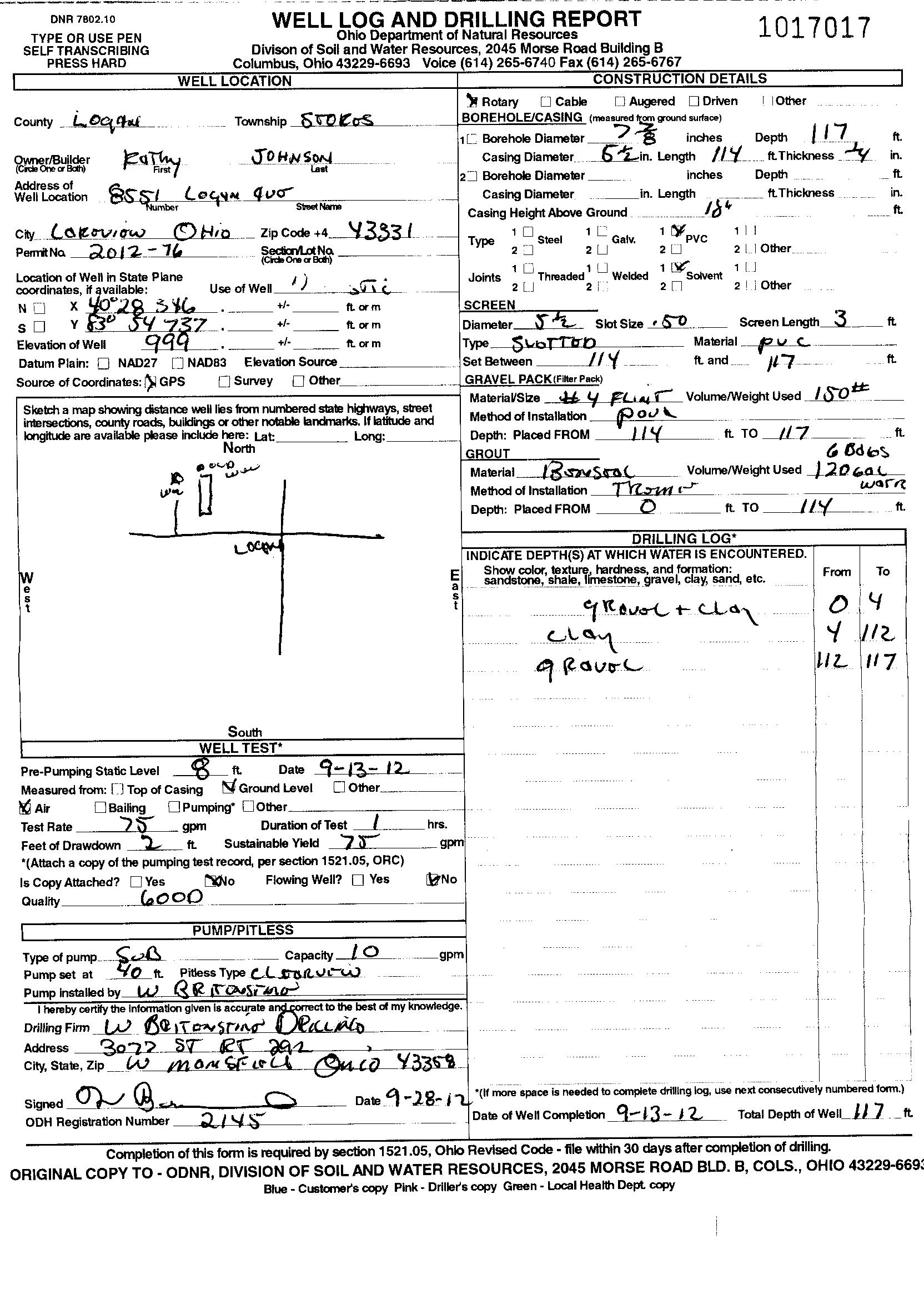
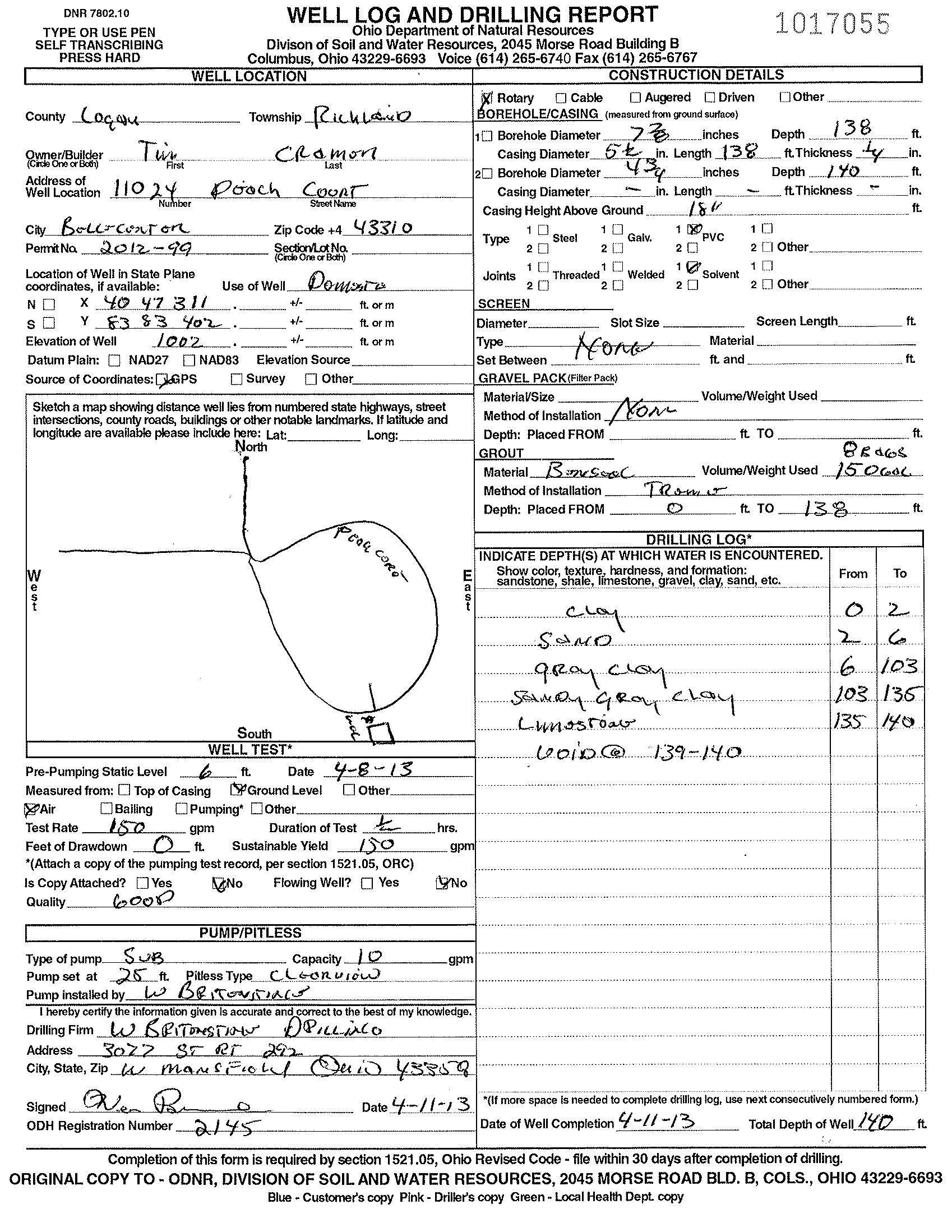
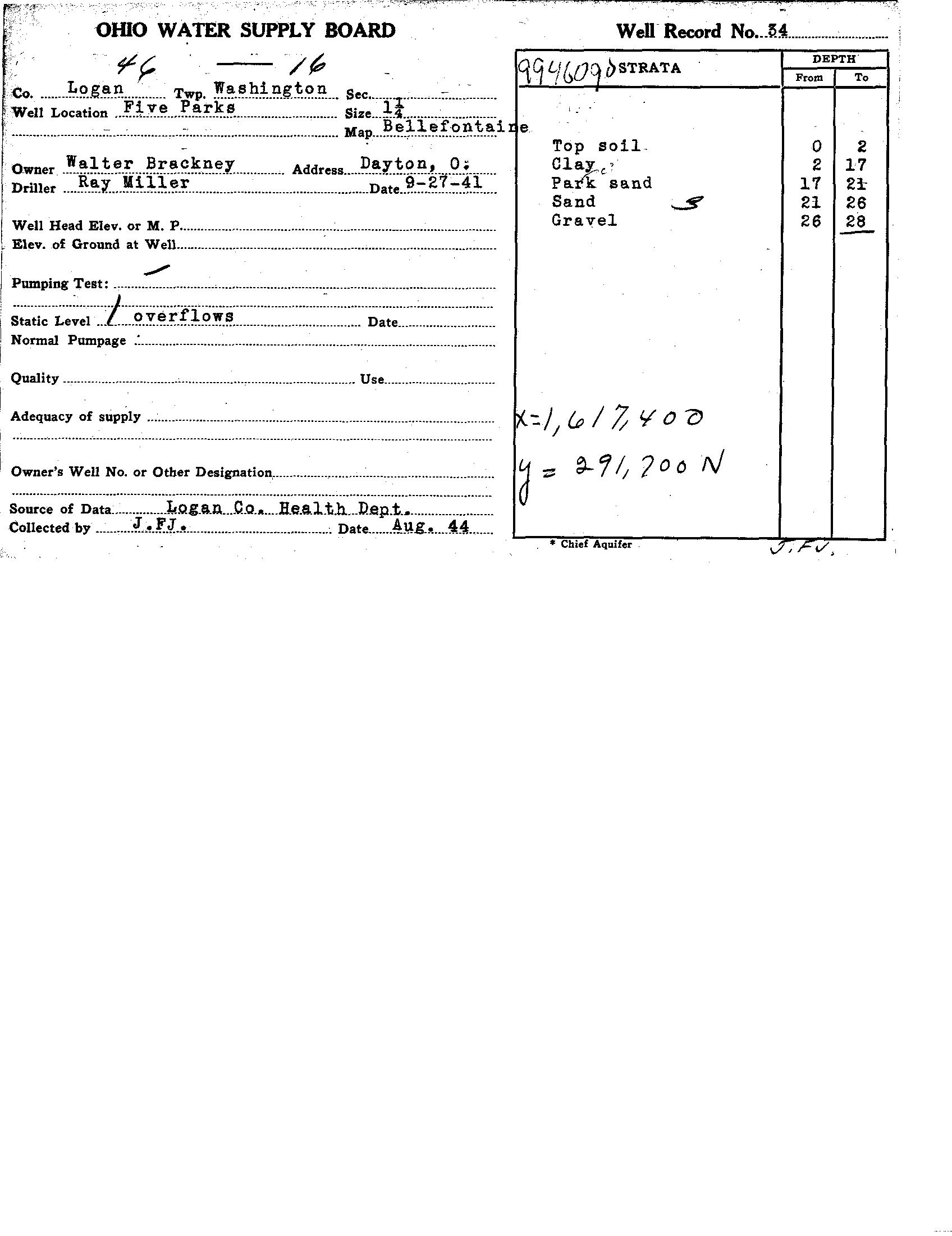
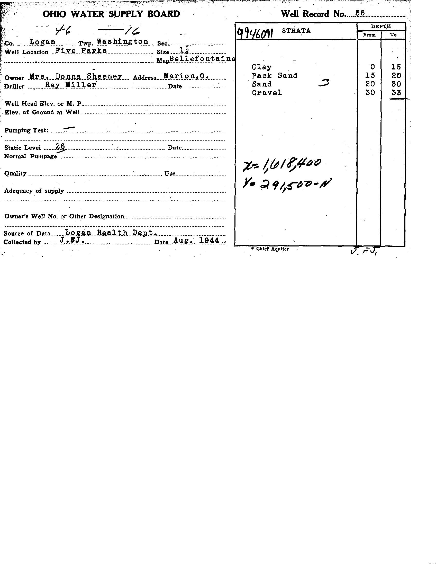
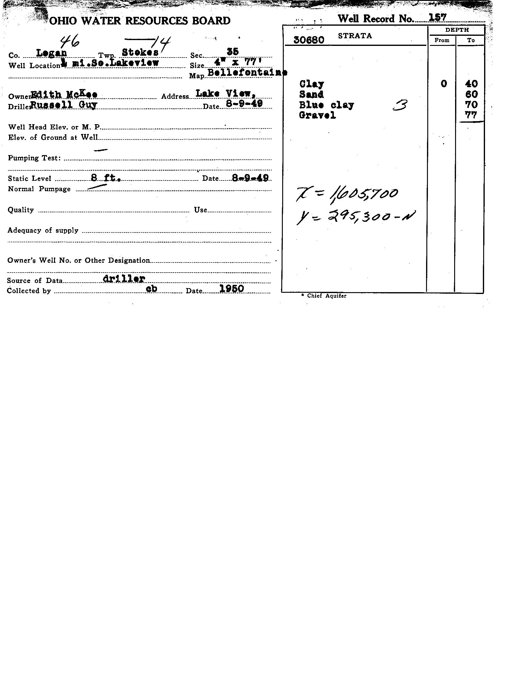


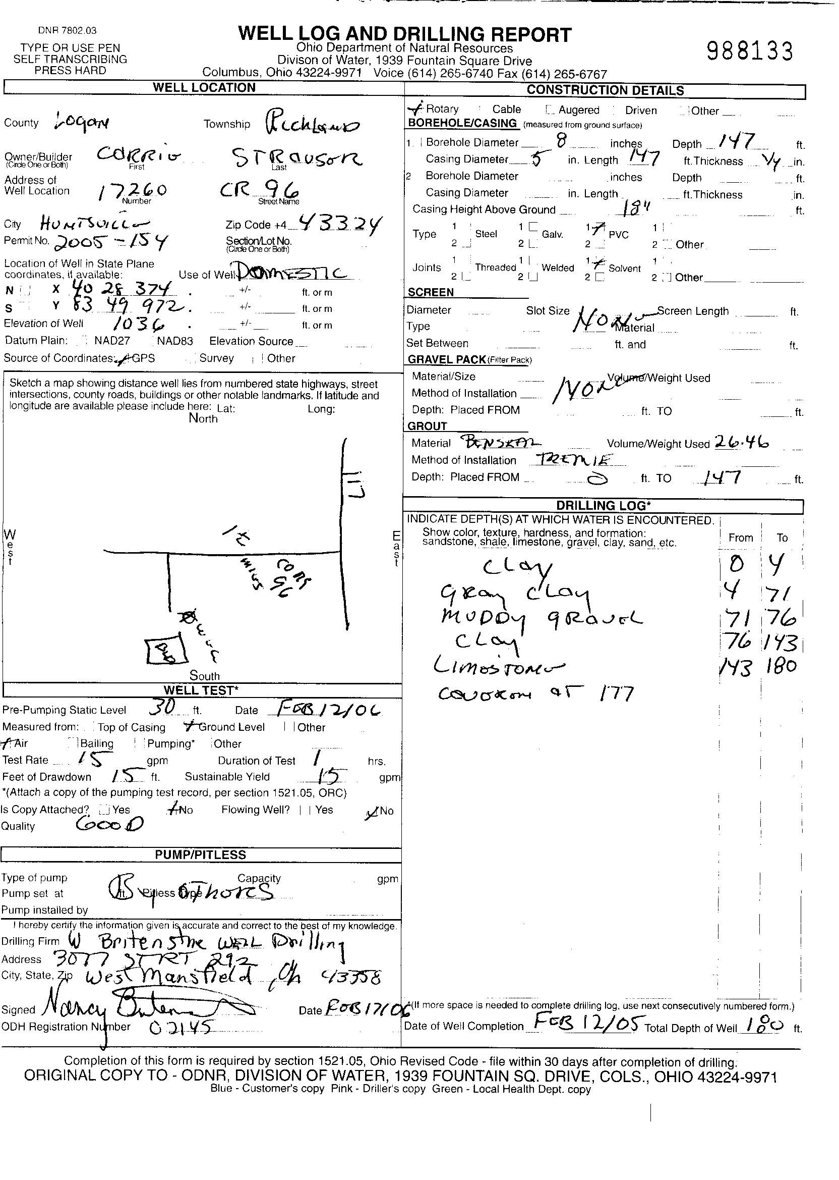


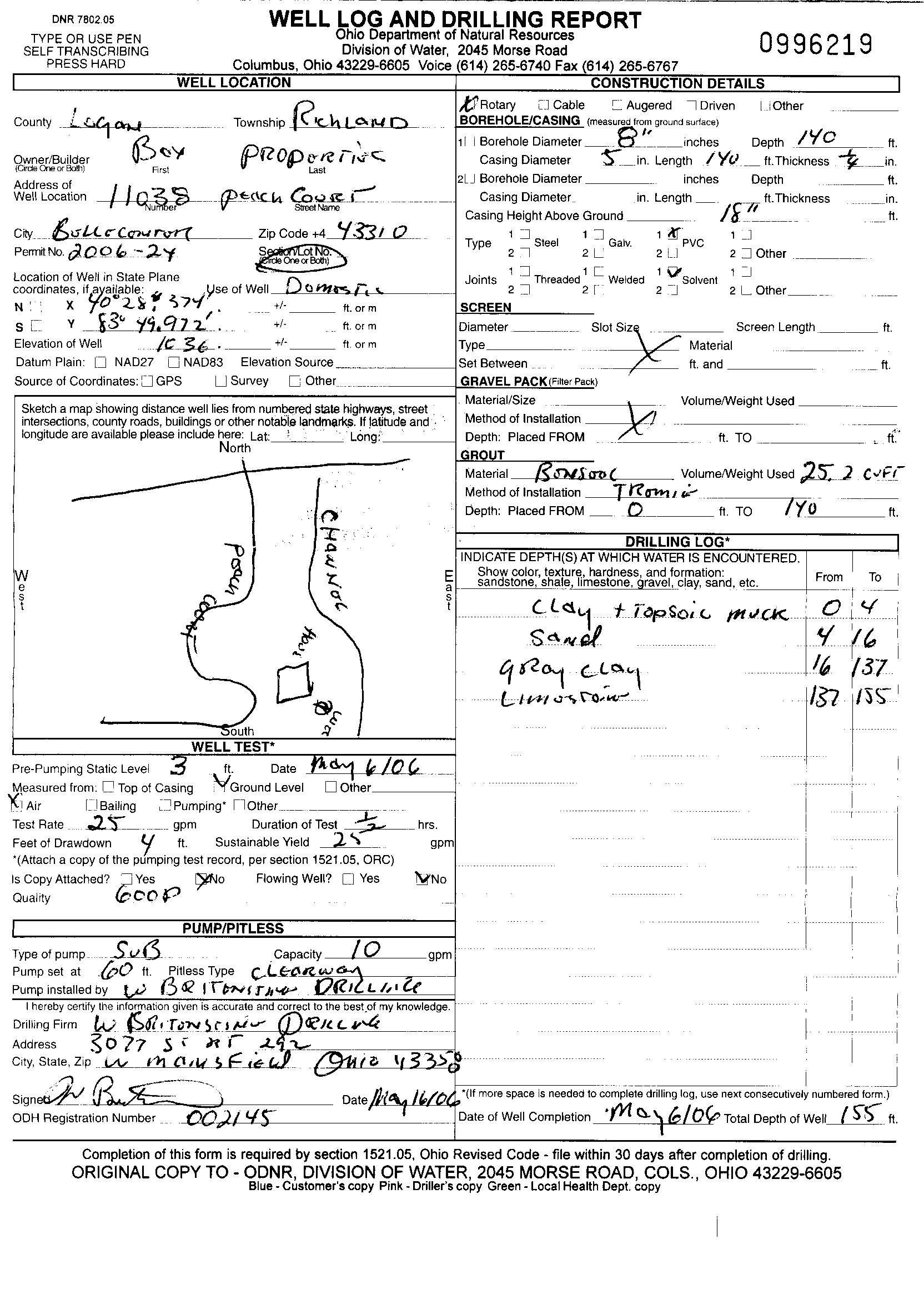
OHIO EPA SWPA