
Transportation Assessment
Crossroads Solar Grazing Center
Morrow County, Ohio
May 2025
Prepared for:
Texas 78702


APPENDIX
APPENDIX
1.0 INTRODUCTION
1.1 PROJECT DESCRIPTION AND PURPOSE
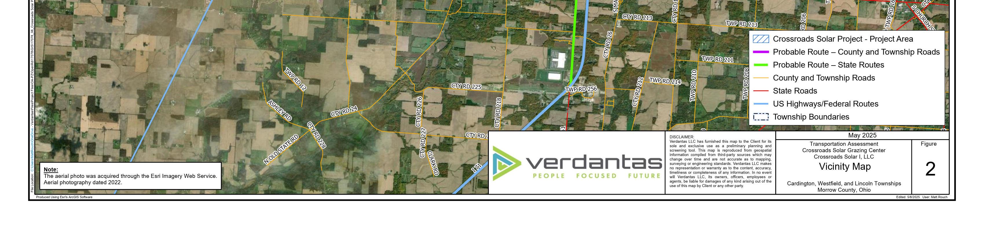
This Transportation Assessment has been prepared for the Crossroads Solar Grazing Center (“Crossroads”). Crossroads is proposing to construct a combined utility-scale solar energy and sheep grazing facility in Cardington, Lincoln, and Westfield Townships in Morrow County, Ohio (the “Project” or the “Facility”). The Project is anticipated to use rows of ground-mounted solar panels to supply up to 94 megawatts AC (MWac) of wholesale power to the existing electric grid while also providing pasture for livestock. All of the Project’s above-ground infrastructure is anticipated to be located within agricultural-style fences to match the surrounding land use and to confine the livestock and protect them from predators. The fenced area is anticipated to be up to 559 acres (the “Solar & Grazing Area”) of an area totaling approximately 726 acres (the “Project Area”). A Site Map and Vicinity Map is included in Appendix A.
The objective of this study is to support an application to the Ohio Power Siting Board (OPSB) for a Certification of Environmental Compatibility and Public Need (Certificate Application), as codified at Ohio Administrative Code (OAC) 4906, as follows:
1. OAC 4906-4-06(F)(3): The applicant shall evaluate and describe the anticipated impact to roads and bridges associated with construction vehicles and equipment delivery. Describe measures that will be taken to improve inadequate roads and repair roads and bridges to at least the condition present prior to the project.
2. OAC 4906-4-06(F)(4): The applicant shall list all transportation permits required for construction and operation of the project and describe any necessary coordination with appropriate authorities for temporary or permanent road closures, lane closures, road access restrictions, and traffic control necessary for construction and operation of the proposed facility.
For the purpose of this report, the following definitions have been used when describing the project (based on OAC 4906-1-01):
• Project Area means all land that contains components of the facility, as well as any real property for which land rights are necessary to be secured in order to construct and operate the facility.
• Facility means the proposed major utility facility and all associated facilities.
• Associated Facility means, for an electric power generation plant or wind farm: rights-of-way, land, permanent access roads, structures, tanks, distribution lines, and substations necessary to interconnect the facility to the electric grid, water lines, pollution control equipment, and other equipment used for the generation of electricity.
1.2 METHODOLOGY
The solar panels will be located in groups at various locations in the Project Area and access to the proposed solar panels for construction and operation will be from State, county, and township roads. Construction of the facility may cause temporary increases in truck traffic on area roadways due to the delivery of materials and equipment.
This evaluation identifies the probable public routes that can be used to construct and operate the facility. Vehicle traffic is anticipated to originate from an Interstate or 4-lane divided State highway. From these routes, 2-lane State highways are anticipated to be used to travel to the Project Area. County and township roads will be used to access private leased parcels that make up the Project Area.
For purposes of this evaluation, Interstate, 4-lane, and 2-lane State highways were not evaluated because it is assumed that these roadways are sufficient to accommodate the construction and operational traffic with respect to load capacity, geometry, and condition.
For the county and township roads, this evaluation includes a desktop study and on-site visual assessment of the probable routes, bridges, and culverts in the Project Area. This evaluation includes the general condition based on visual assessment of culverts and bridges, general pavement conditions, vertical changes in grade, and overhead height obstructions If needed, this evaluation identifies locations where improvements to the road are likely needed to accommodate the size of the delivery and construction vehicles.
Research for state permits that are necessary for hauling the materials and equipment is also included in the evaluation. Video was collected from all the reviewed probable routes as well as photographs of select features noted during the evaluation.
1.3 VEHICLE TYPES
The size and types of vehicles needed to deliver construction equipment, construction materials, and facility components include flatbed or tractor-trailer equipment delivery vehicles and multi-axle dump trucks. In addition, typical automobiles and pickup trucks are anticipated to be used to transport construction staff and other incidental truck trips.
1.4 DESIGN VEHICLE CHARACTERISTICS
Transportation of construction equipment and materials and facility components is anticipated to be completed using conventional transportation vehicles such as fixedbed trucks or tractor-semi-trailers (AASHTO WB-67). Construction equipment such as excavators, bull dozers, and wheel tractor-scrapers is anticipated to be transported to the site on fixed-bed or tractor-semi-trailer low-boy vehicles. Multi-axle dump trucks may also be used. The vast majority of the vehicles are expected to be of legal weight and dimensions. Some limited components, such as switchgear or transformers for switchyards and substations, may require the use of overweight/oversize vehicles.
2.0 PROBABLE ROUTE EVALUATION
2.1 ROADWAY CHARACTERISTICS
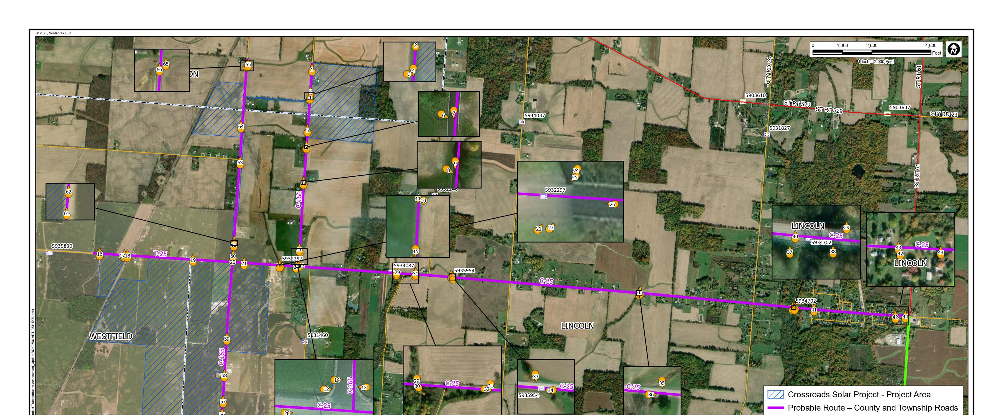
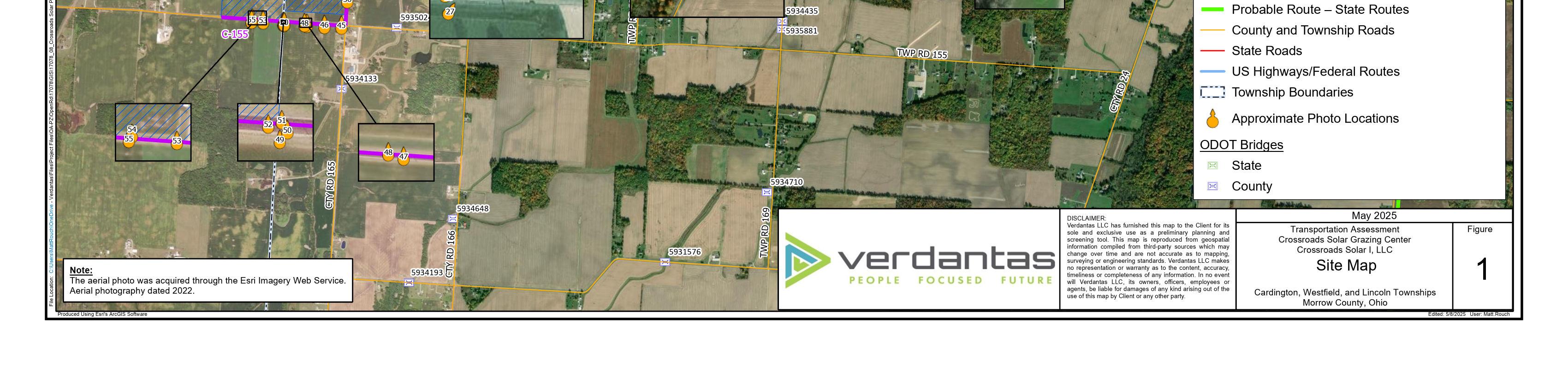
An evaluation and visual assessment of the probable routes were conducted on January 15 and February 2, 2024, by traveling the roadways listed below (see Figure 1 in Appendix A for location of probable routes). Annual Average Daily Traffic (AADT) data for the probable routes was obtained from the Ohio Department of Transportation (ODOT) Traffic Monitoring Management System (TMMS)1, if available. Based on field observations, we do not expect construction or operation of the Facility to create any significant delays for the traveling public. Table 1 summarizes the existing conditions of the roadways.
TABLE 1 ROADWAY CHARACTERISTICS
Notes:
- A – Posted 25 mph from SR-61 to approx. 0.65 miles west (through Village of Fulton).
- AADT – Annual Average Daily Traffic (2022)
- NP – not posted; (55 mph per Ohio State Law)
- N/A – not available
- Lanes are assumed to be a minimum of 8.5 feet wide
- Pavement Condition:
• Excellent – recently paved.
• Good – pavement appears stable with minor cracking and other pavement distress indicators.
• Fair – pavement appears stable but may have a higher amount of transverse and longitudinal cracking and other distressed pavement indicators such as edge cracking, rutting, and weathering. Potholes may be present.
• Poor – pavement is severely distressed with excessive cracks, potholes, rutting, and deterioration.
C-25
This road is in good overall condition exhibiting minor surface wear. Minor raveling and transverse cracking were observed to be frequent throughout the road segment. It was noted that most transverse cracks observed were located over culverts and bridges. The easternmost portion of this road segment through the Village of Fulton (approx. 0.65-mile
1 Ohio Department of Transportation, Traffic Monitoring Management System, http://odot.ms2soft.com/
length up to SR-61) contained minor occasional longitudinal cracking. This road segment contains no striping. This road has relatively flat grades with no abrupt grade changes. Note that the westernmost end of this evaluated road segment turns into T-25 where the road crosses into Westfield Township from Lincoln Township. See below for a detailed description of the evaluated portion of T-25.
T-25
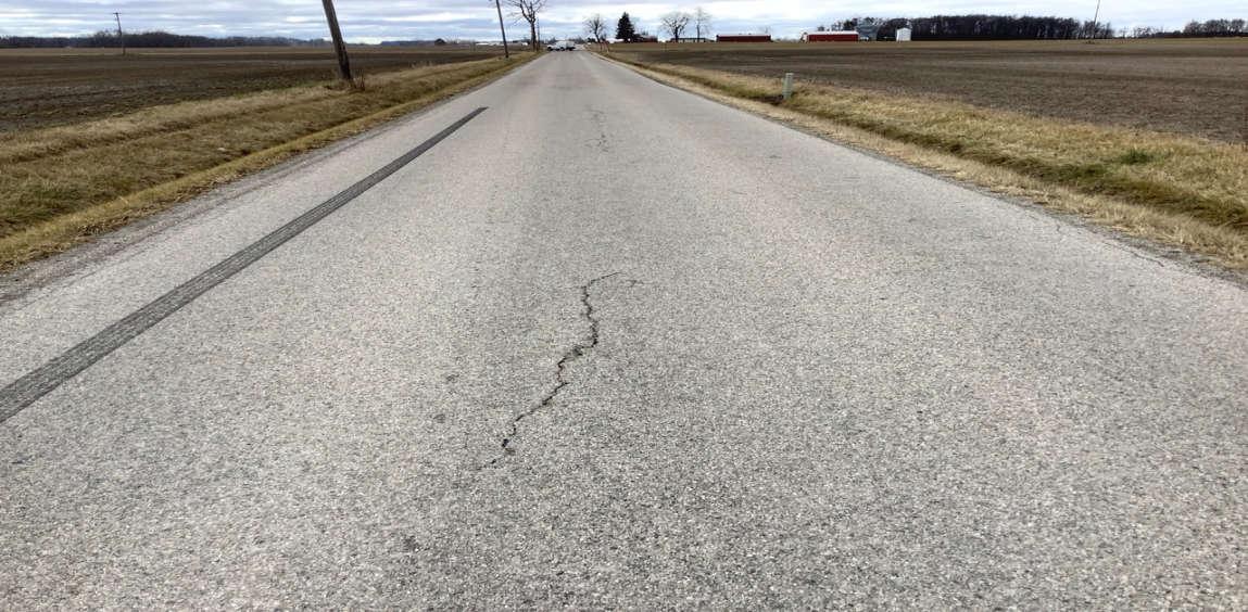
This road segment begins where C-25 crosses into Westfield Township from Lincoln Township. This road segment is in good overall condition exhibiting moderate surface wear, extensive pavement bleeding, and occasional minor rutting. This road segment contains only centerline striping, has relatively flat grades with no abrupt grade changes, and one railroad crossing.
C-155
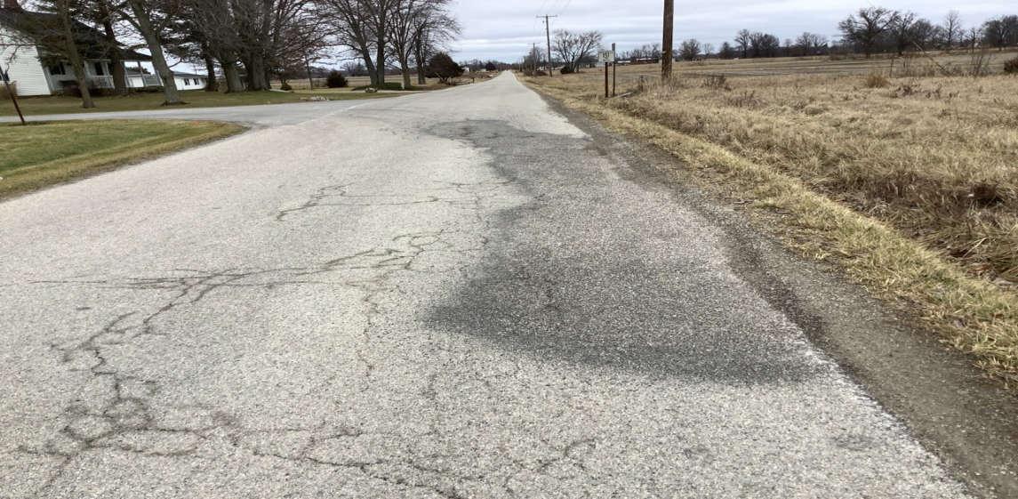
This road is in good condition exhibiting normal surface wear. Observed pavement distresses include frequent areas with sporadic cracking, and occasional minor transverse and longitudinal cracking. Occasional minor raveling and potholes were noted. A loss of aggregate surface along the edges of the road pavement was frequently noted. This road segment contains no striping. This road segment has relatively flat grades with no abrupt grade changes.
C-165
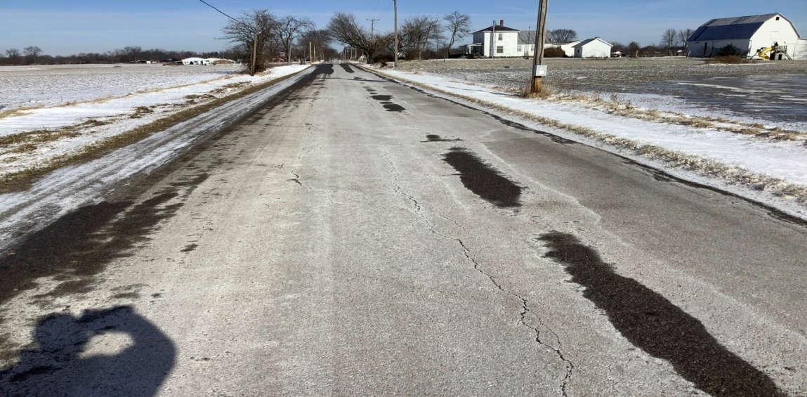
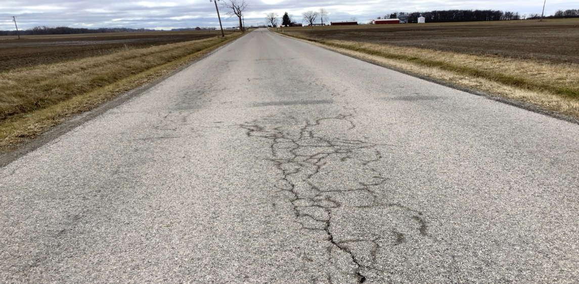
This road is in good condition exhibiting normal surface wear. Frequent edge cracking, longitudinal cracking, and transverse cracking was observed throughout. Frequent areas of sporadic cracking spanning the width of the roadway was observed. Minor raveling of the surface was frequent, while occasional severe raveling was observed to cause some rough/pitted areas forming potholes. A loss of aggregate surface along the edges of the road pavement was frequently noted. What appeared to be one surface patch/repair area in poor condition was noted near the intersection of T-151. This road segment contains no striping. This road segment has relatively flat grades with no abrupt grade changes.
C-166
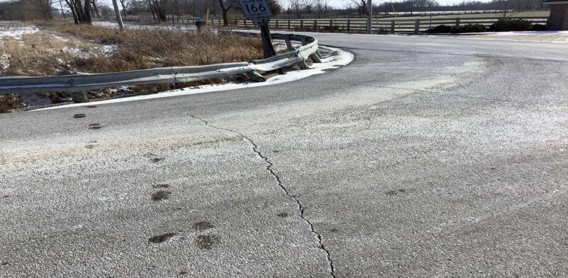
This road is in good condition exhibiting minor surface wear. Observed pavement distresses included frequent minor edge cracking and transverse cracking, and extensive minor longitudinal cracking. This road contains no striping. This road has relatively flat grades with no abrupt grade changes.
Summary
All these roads are suitable for equipment delivery and construction traffic in their current condition. Example areas of concern for all the roads were photographed and are included in Appendix B. The locations of the photos are shown on Figure 1 in Appendix A.
2.2 BRIDGE AND ROAD LOAD RESTRICTIONS
There were no posted load restrictions on the probable routes in the Project Area. There are four ODOT numbered “bridges” located in the Project Area; however, two of these were observed to instead be culvert pipes:
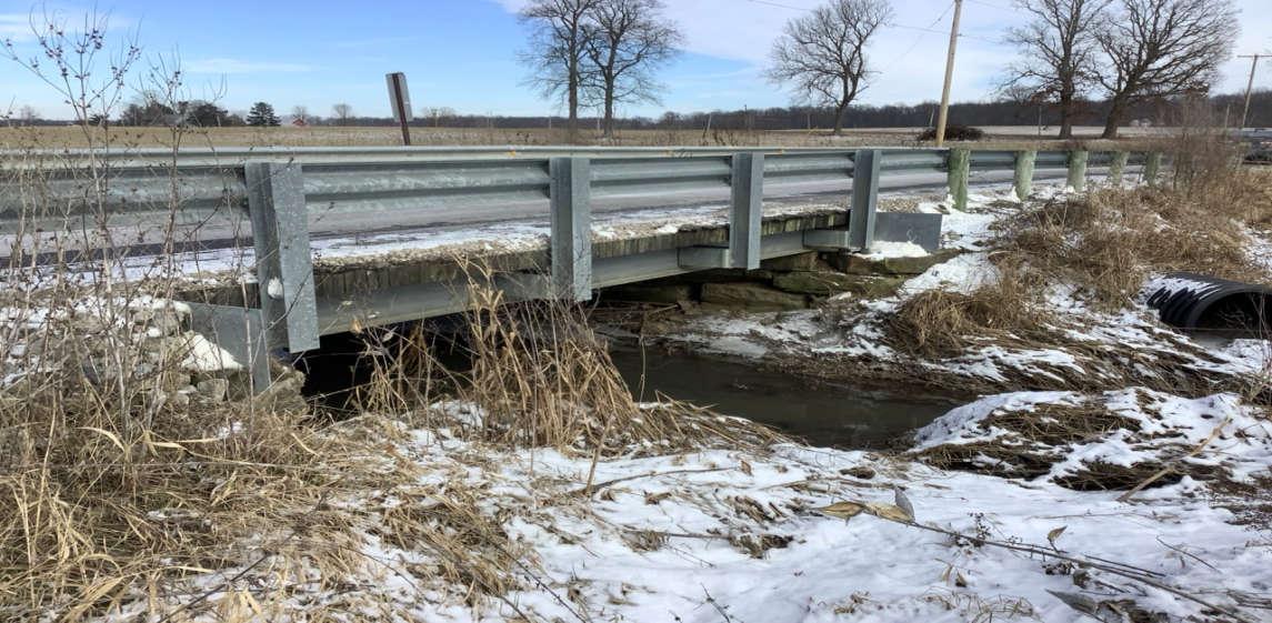
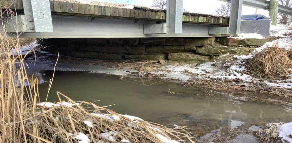
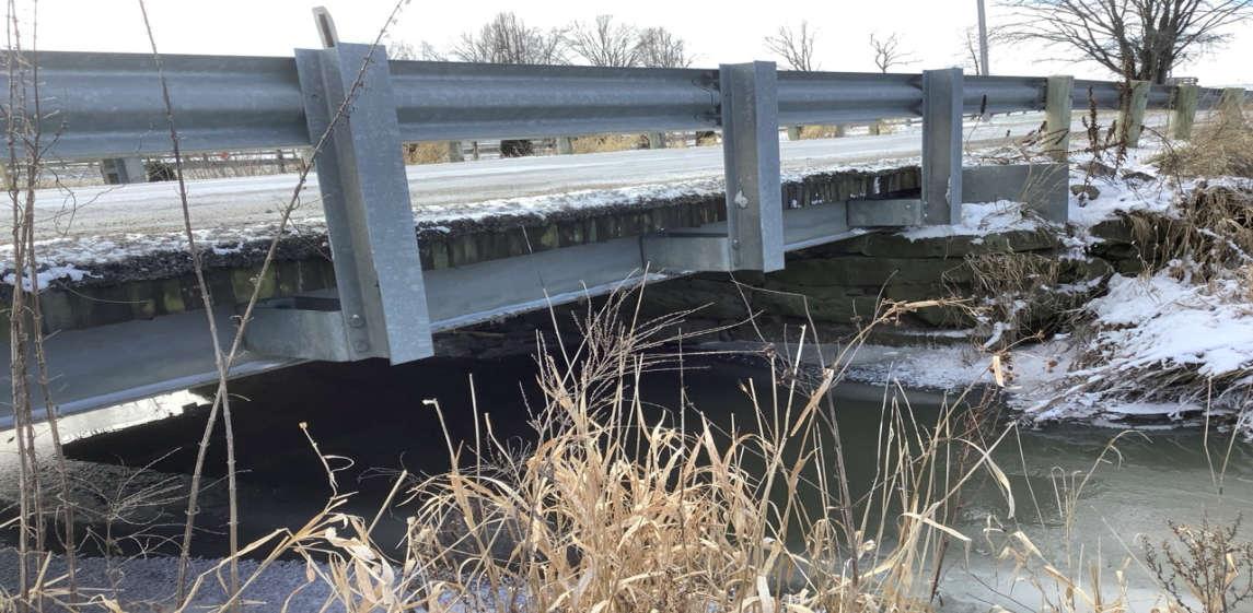
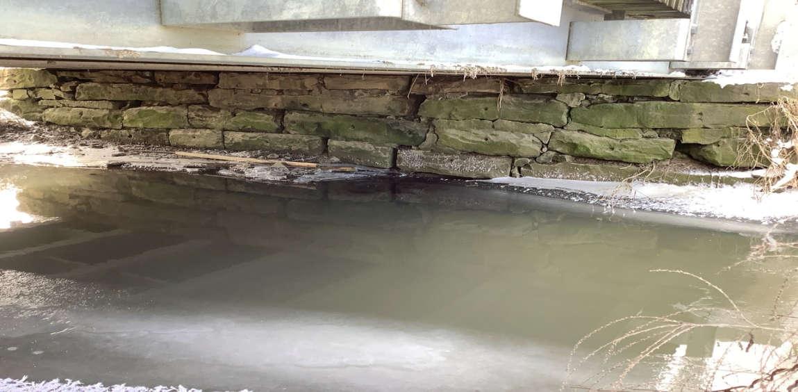
1. Bridge 5932297 on C-25 is a steel beam bridge in good overall condition. The steel beams rest on stone slab abutments, and the bridge has a wooden deck beneath asphalt pavement. The stone slabs appeared to be in fair condition with some deterioration of the stone noted. The asphalt deck was in overall good condition with some observed longitudinal and edge cracking with minor spalling. The guardrails were also in good condition.
2. Bridge 5934087 on C-25 is a dual CMP culvert. Refer to Section 2.3 for a description of culvert characteristics on this road.
3. Bridge 5935954 on C-25 is a dual CMP culvert. Refer to Section 2.3 for a description of culvert characteristics on this road.
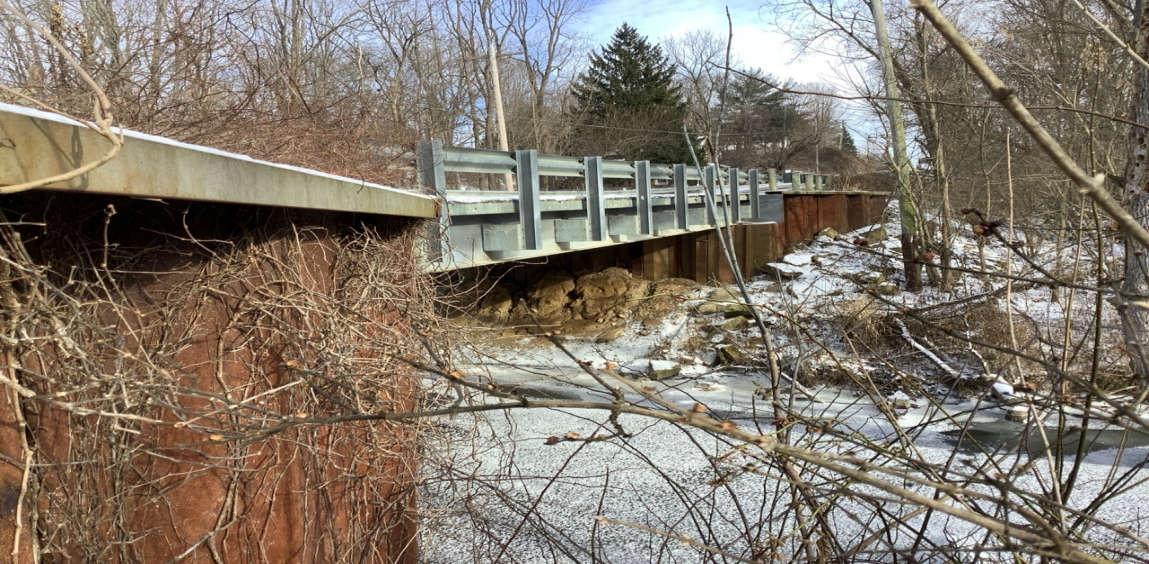
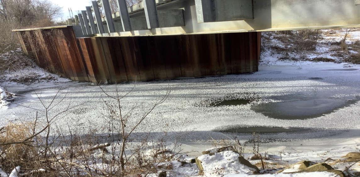
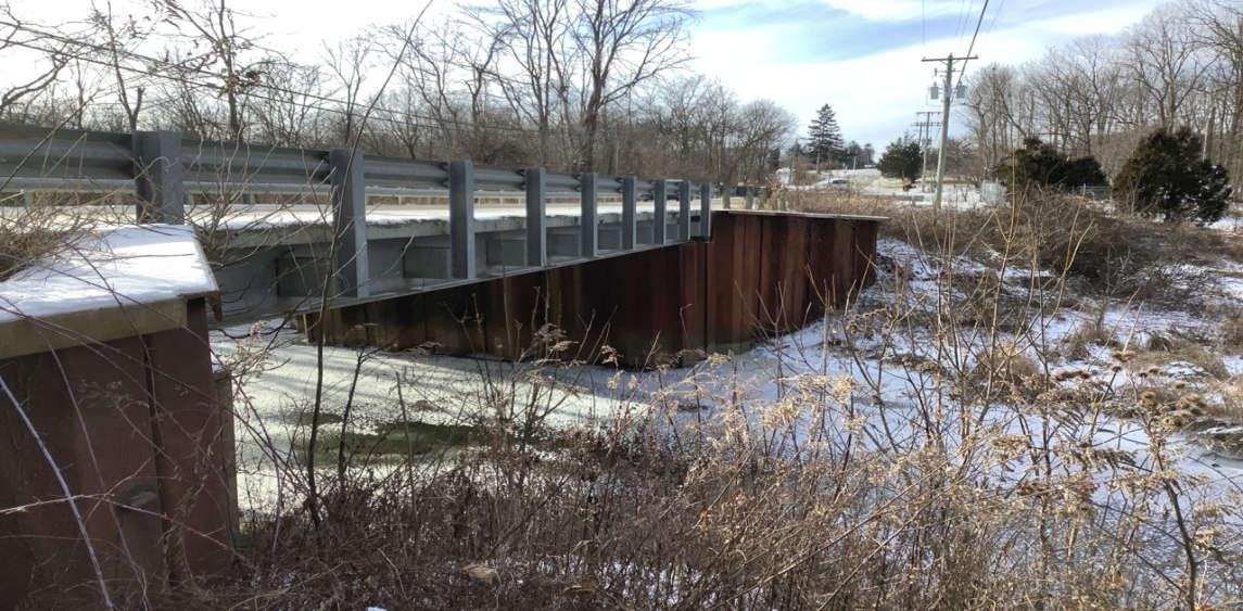
4. Bridge 5934702 on C-25 is a steel beam bridge in good overall condition. This bridge contains sheet piling for the abutments and wingwalls, and an asphalt deck. The sheet piling appeared to be in good stable condition. Minor transverse cracking was observed on the asphalt deck at the bridge approach joints. The guardrails appeared to be in good condition.
The Morrow County Engineer’s Office was contacted by Verdantas in February 2025 to determine if there are any restrictions on roadways or culverts on the probable routes that were evaluated. They were also contacted for providing information regarding any planned construction projects on the probable routes within the next two years. As of 5/5/25, no information has been received.
2.3 CULVERT CHARACTERISTICS
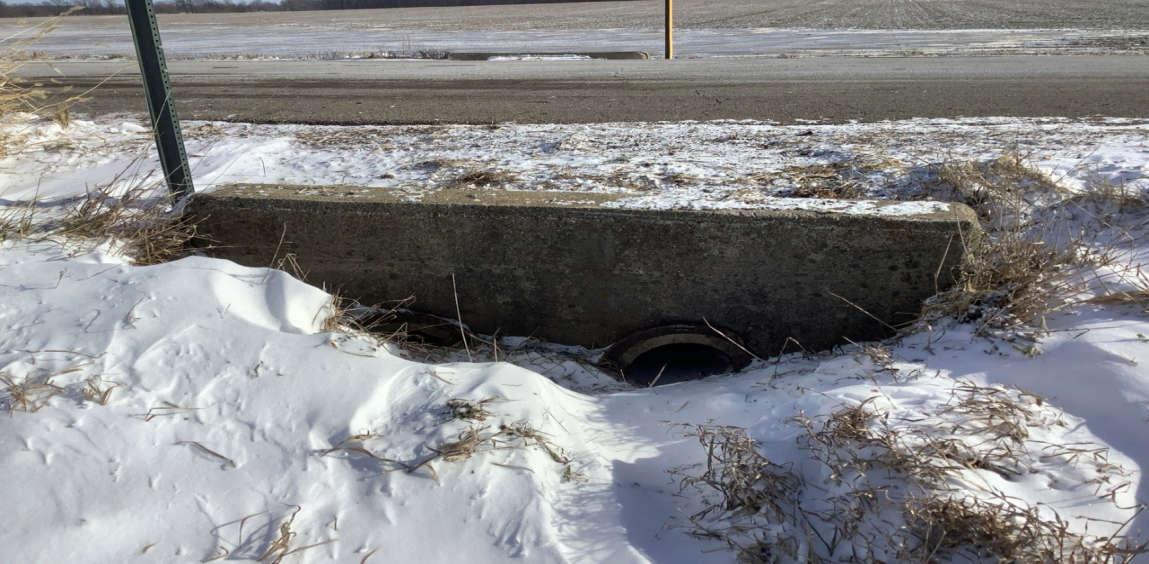
Culverts (where visible) were visually examined to determine their condition and if adequate cover is present. For purposes of this evaluation, adequate cover means there is more than one foot of cover over the culvert (inclusive of the pavement). The condition of the culvert was limited to a visual review to determine if there is distortion in the shape (e.g., out of round) or evidence of corrosion (for steel culverts). The condition of concrete culverts is limited to evidence of cracking or surface spalling. The order in which culverts are described below align with their order presented along that particular road within the photo pages of Appendix B. Culvert characteristics described below are reflective of their observed conditions during the visual assessments conducted on January 15, 2024 and February 2, 2024.
C-25
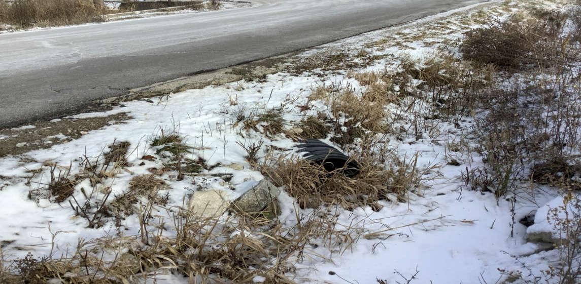
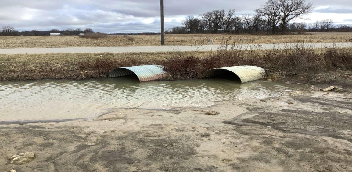
There are six culverts observed on this road, from west to east. The first culvert is a highdensity polyethylene (HDPE) pipe in good condition. The second culvert consists of dual corrugated metal pipes (CMP) in good condition (ODOT Bridge #5934087). This second
culvert contains stacked stones to stabilize the embankment, and the north inlet is noted to be partially blocked by debris. The third culvert is an HDPE pipe in good condition. The fourth culvert consists of dual CMPs in good condition (ODOT Bridge #5935954), though the pipes are slightly out of round. The fifth culvert is an HDPE pipe in good condition. The sixth culvert is a newer concrete box culvert in good condition. All culverts on this road appear to have adequate cover except for the first culvert. All culverts on this road have stable embankments. The pavement over all culverts on this road is observed to be in good condition with minor surface wearing. The pavement over the first, second, third, fourth, and sixth culverts contains minor transverse cracking. The pavement over the fifth culvert contains a concrete patch with some minor cracking and deterioration along its edges.
T-25
There are no culverts observed along this road segment.
C-155
There are two culverts on this road segment, from east to west. The first culvert is a CMP in good condition, though the southern pipe outlet is bent slightly out of round. The second culvert is an HDPE pipe in good condition. Both culverts appear to have adequate cover and stable embankments. The pavement over each of these culverts is in good overall condition, with some transverse cracking over the pipes.
C-165
There are two culverts on this road segment, from north to south. The first culvert is a dual CMP in good condition, however, each of the dual western and eastern outlet pipes are bent slightly out of round with some minor corrosion. The second culvert is also a dual CMP in good condition, with some minor corrosion. Both culverts appear to have adequate cover and stable embankments. The pavement over each of these culverts is in good overall condition, with some transverse cracking over the second culvert.
C-166
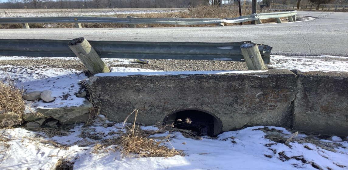
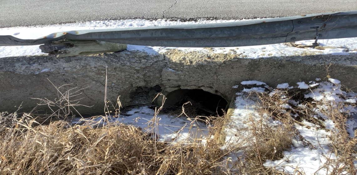
There are five culverts on this road, from south to north. The first culvert is in overall good condition and appears to be a steel pipe at its western end, and a reinforced concrete pipe (RCP) at its eastern end. This first culvert has concrete headwalls that are exhibiting some minor deterioration, and the guardrail at both ends of this culvert is damaged. The second culvert is a CMP in good condition. The third culvert is an RCP in good condition. This third culvert has concrete headwalls, and some minor deterioration on the west headwall. The fourth culvert is a steel pipe in good condition, with a concrete headwall at its west end. The fifth culvert consists of dual RCPs in good condition with concrete headwalls. The first, fourth, and fifth culverts appear to have adequate cover, while the others do not. All culverts on this road have stable embankments. The pavement over all culverts on this road is in good condition with minor surface wearing, and a combination of transverse cracking and/or longitudinal cracking.
2.4 OVERHEAD AND WIDTH RESTRICTIONS
The roads were investigated for width and height limitations. Permanent structures that cross over the road and restrict the clearance for oversized loads (such as bridges and
overpasses) were not found along the evaluated routes. For overhead cables, the national standard for minimum clearance over roads is 15.5 feet, and cables cross over the studied routes in numerous locations. Heights of overhead cables were not measured; however, no cables appear to be potentially vertically obstructive. In the event a cable presents an obstruction, utility providers can temporarily or permanently raise the cables and/or move the poles. Therefore, cables should not be a limiting feature for use of the roads. There were no observed potential width restrictions along the evaluated routes.
2.5 POSTED CAUTION SIGNS
There are no posted caution signs on the roadways that were reviewed.
2.6 LOCAL SCHOOL AND PUBLIC TRANSPORTATION INFORMATION
The Project Area is located within Cardington-Lincoln Local School District. The following information was obtained from the Ohio Educational Directory System (OEDS) Website2 .
Cardington-Lincoln Local School District
Cardington-Lincoln Elementary School
121 Nichols St.
Cardington, Ohio 43315
P, K-4 enrollment: 472
Cardington-Lincoln Middle School
349 Chesterville Ave.
Cardington, Ohio 43315
5-8 enrollment: 400
Cardington-Lincoln High School
349 Chesterville Ave.
Cardington, Ohio 43315
9-12 enrollment: 387
The northern portion of the Project Area is located approximately 1.0 mile south of the Cardington-Lincoln Elementary School, and approximately 2.0 miles south of the Cardington-Lincoln Middle and High Schools. Due to the rural area, many of the students are transported by bus. The number of buses and stops within the Project Area would be limited due to the total number of students and low density of homes. Impacts to school bus routes would be minimal based on:
1. No planned road closings;
2. Many project deliveries would occur in the middle of the day; and 3. Wide loads requiring escorts are negligible.
2 Ohio Department of Education Website, Last Updated February 2022, https://oeds.ode.state.oh.us/
There are no public bus transit systems in the Project Area. There is one railroad line running northeast/southwest at the western end of the Project Area.
3.0 POTENTIAL IMPACTS TO ROADWAYS
The development of a solar electric generating facility has the potential to create transportation impacts because of short-term construction activities. The following sections estimate the traffic for construction vehicles during the project, summarize permitting and road use agreements, and outline steps for mitigating potential impacts to roadways.
3.1 ESTIMATED FUTURE TRAFFIC
To deliver the construction equipment, materials, and construction workers during the construction of the facility, the probable routes are likely to experience increased truck traffic. Historic data for construction of solar electric generating facilities indicates that there are approximately 17 to 18 delivery vehicle trips per MW of power. This project is projected to be 94 MW; therefore, there are estimated to be 1,598 to 1,692 vehicle trips for the project.
Most of the vehicles are expected to be of legal weight and dimensions. Some limited components such as switchgear or transformers for switchyards and substations may require the use of overweight/oversize vehicles.
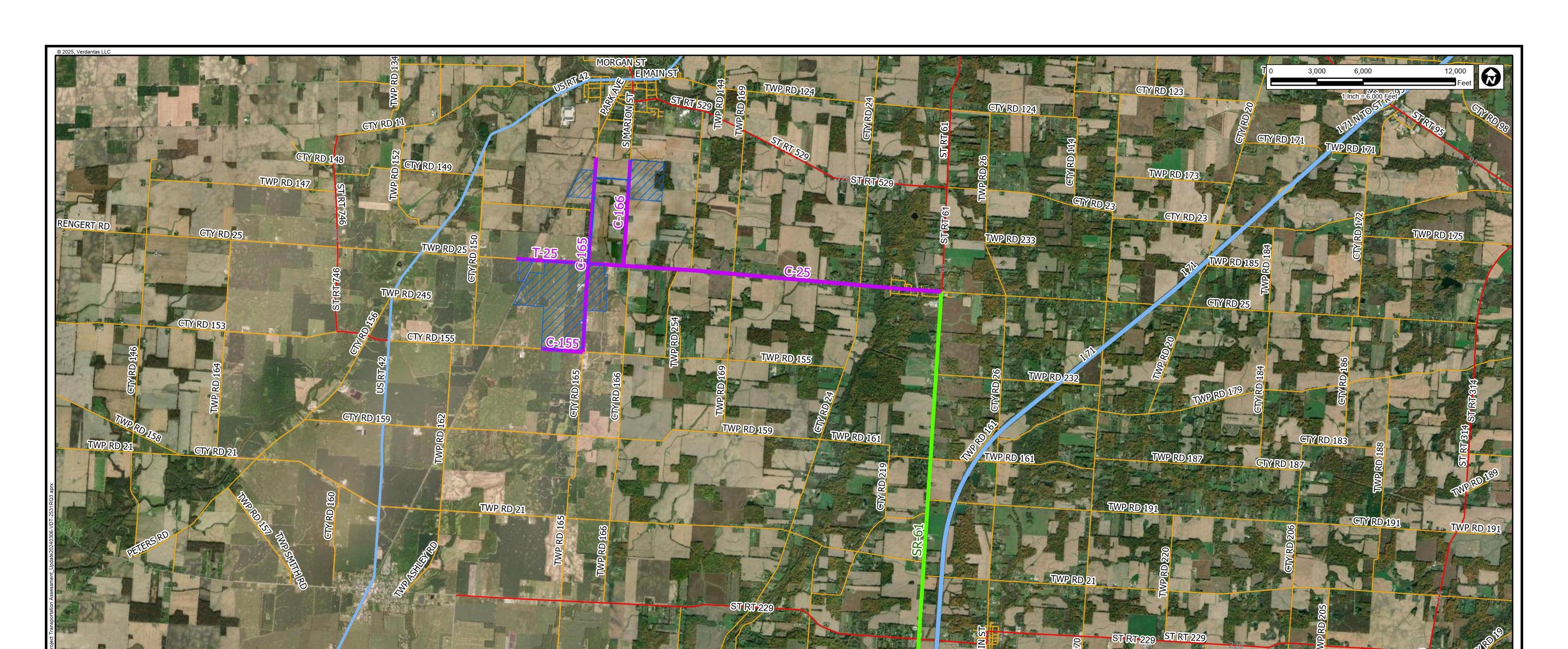
A final delivery route has not yet been finalized, but delivery of facility components to the Project Area is anticipated to be from the south by way of I-71, to SR-61, to C-25 (see Figure 2 in Appendix A). Within the Project Area, county and township roads will be used to deliver equipment and materials. The probable routes are shown on Figure 1 in Appendix A.
For many of the delivery vehicles that are of legal dimensions, no delays to local traffic should be experienced except where the delivery vehicles may need to travel on narrow roadways (less than 2 lanes in width). However, the delays to local traffic should be minimal due to the low traffic volume in the Project Area. When delivery vehicles are travelling on narrow roadways or when there is an occasional oversized vehicle, traffic control is anticipated to be utilized to manage local traffic. Because this is an agricultural area, heavier use of roadways by local farmers during planting and harvest seasons may occur Prior to construction, a Traffic Control Plan is expected to be prepared that describes the traffic management procedures during construction, and it is anticipated to be shared with local law enforcement, schools, and local landowners.
Final driveway locations should take into consideration of the final facility layout, location with respect to other driveways and roadways, topography, and vertical and horizontal sight distance.
During operation and maintenance of the facility, traffic volumes are anticipated to be similar to pre-construction conditions because solar electric generating facilities are normally unmanned. The traffic is expected to be occasional maintenance vehicles and additional traffic would be negligible.
3.2 PERMITS AND AGREEMENTS
Prior to construction, the contractor will obtain all necessary permits from ODOT and the County Engineer. The County Engineer may require a Road Use and Maintenance Agreement (RUMA) for construction activities. This agreement is anticipated to include procedures for temporary road closures, lane closures, road access restrictions and traffic control. For driveway access on County and Township roads, a permit will be required from the County Engineer.
Road and County-maintained ditch crossings (e.g., underground, or overhead collection and transmission lines) will require a permit from ODOT or the County Engineer.
Special Hauling Permits are required when loads exceed legal dimensions or weights. Table 2 summarizes the characteristics of vehicle characteristics without Special Hauling Permits for State of Ohio highways.
For construction of the Facility, most of the vehicles are expected to meet current legal dimensions and weights. Therefore, Special Hauling Permits are only anticipated for a few vehicles that may exceed these criteria such as switchgear or transformers.
TABLE 2
DIMENSIONAL
CRITERIA FOR VEHICLES WITHOUT SPECIAL HAULING PERMITS
Width of vehicle, inclusive of load
Height of vehicle, inclusive of load 13.5 Feet
Length of vehicle, inclusive of load and bumpers 85 Feet
Total Weight of vehicle with 4 or more axles A, inclusive of load 80,000 pounds B
Notes:
A. Long quad axle group defined as four adjacent axles with spacing greater than 4 feet but not more than 16 feet.
B. Maximum weights are determined by the gross weight of the load and the vehicle, the maximum axle load, the wheel load, and the axle spacing dimensions. See Ohio Department of Transportation Guidance OS-8 for details on determining maximum weights.
3.3 POTENTIAL MITIGATION
This study has determined that very little impact to roads associated with construction vehicles and material delivery is anticipated during the construction of the Facility. Final civil engineering design is anticipated prior to construction to ensure all transportationrelated activities are accounted for and approved by the County Engineer.
All roads should be monitored during construction for deterioration to ensure they are safe for local traffic. The volume and/or weight of construction traffic may cause accelerated pavement deterioration or stress on drainage structures that could necessitate temporary repairs. After completion of construction activities, there may be improvements required to return the roadways and drainage structures to preconstruction conditions. These requirements are anticipated to be outlined in the RUMA with the County Engineer.
In the event impacts do occur, the following mitigation techniques are anticipated to be utilized to avoid or minimize transportation-related impacts and/or to provide long-term improvement to the local road system:
Insufficient Roadway Width
• Temporary traffic control.
• Rerouting over-width vehicles to wider roadways.
Insufficient Vertical Clearance
• Temporarily raising overhead utility lines.
• Rerouting over-height vehicles to roadways with sufficient vertical clearance.
Poor Pavement Condition or Insufficient Pavement Durability
• Roadside drainage improvements
• Pavement patching
• Rerouting heavy-loaded vehicles to avoid insufficient pavement.
Insufficient Cover Over Drainage Structures
• Adding temporary gravel and/or asphalt cover over structures.
• Using bridge jumpers to clear structures.
• Replacing structures during or after construction if damaged by construction traffic.
• Rerouting heavy-loaded vehicles to avoid structures.
Poor Structure Condition
• Using bridge jumpers to clear structures.
• Rerouting heavy-loaded vehicles to avoid structures.
Inadequate Bridge Capacity
• Using bridge jumpers to clear bridges.
• Rerouting heavy-loaded vehicles to avoid bridges.
Insufficient Roadway Geometry
• Temporary traffic control.
• Rerouting over-sized vehicles to avoid insufficient roadway geometry.
• Temporary plan adjustments to roadways with insufficient horizontal geometry.
4.0
CONCLUSIONS
Based on information collected during the field investigation, vehicle assumptions, and information available from ODOT, sufficient infrastructure exists via Interstate, State, and local roads to construct the Facility The vast majority of the vehicles transporting construction equipment, materials and workers are expected to meet legal load and dimensional limits. Some limited components such as switchgear or transformers for switchyards and substations may require overweight and/or oversize vehicles.
In the event overweight and/or oversized loads are necessary for construction, Special Hauling Permits will be obtained from the Ohio Department of Transportation (ODOT). All work is expected to be coordinated and approved by the appropriate regulatory agencies prior to construction.
For most of the delivery vehicles that are of legal dimensions, no delays to local traffic should be experienced except where the delivery vehicles may need to travel on narrow roadways. However, the delays to local traffic should be minimal due to the low traffic volume in the Project Area. When delivery vehicles are traveling on narrow roadways or when there is an occasional oversized vehicle, traffic control is anticipated to be utilized to manage local traffic. Because this is an agricultural area, heavier use of roadways by local farmers during planting and harvest seasons may occur. Prior to construction, a Traffic Control Plan is expected to be prepared that describes the traffic management procedures during construction, and it is anticipated to be shared with local law enforcement, schools, and local landowners.
Final delivery routes have not yet been determined, but delivery of facility components to the Project Area is anticipated to be from the south by way of Interstate 71 to State Route 61 to C-25. Within the Project Area, county and township roads will be used to deliver equipment and materials. Portions of C-25, T-25, C-155, C-165, and C-166 are the recommended routes.
Once the final facility design is complete and the final vehicle characteristics can be determined, this information is anticipated to be finalized with the County Engineer as part of a RUMA.
All roads should be monitored during construction for deterioration to ensure they are safe for local traffic. The volume and/or weight of construction traffic may cause accelerated pavement deterioration or stress on drainage structures that could necessitate temporary repairs. After completion of construction activities, improvements may be required to return the roadways and drainage structures to pre-construction conditions.

APPENDIX B
PHOTO PAGES

Transportation Assessment
Roadway Photographs
Morrow County, Ohio
Date Taken:
January 2024
Project Number: 17078
File Name: 17078.0001.XLSX
PHOTO 1: Pavement distress (transverse and longitudinal cracking) on C-166, looking south.
PHOTO 2: Pavement distress (longitudinal cracking) on C-166, looking north.
Crossroads Solar Grazing Center

Crossroads Solar Grazing Center
Transportation Assessment
Roadway Photographs
Date Taken:
January 2024
Project Number: 17078
File Name:
Morrow County, Ohio 17078.0001.XLSX
PHOTO 3: Dual RCP culvert on C-166, looking east.
PHOTO 4: Pavement distress (transverse and longitudinal cracking) over dual RCP culvert on C-166, looking south.

Crossroads Solar Grazing Center
Transportation Assessment
Roadway Photographs
Morrow County, Ohio
Date Taken:
January 2024
Project Number: 17078
17078.0001.XLSX File Name:
PHOTO 5: Pavement distress (edge cracking) on C-166, looking north.
PHOTO 6: Steel pipe culvert on C-166, looking southeast.
Crossroads Solar Grazing Center Transportation Assessment

Date Taken:
Roadway Photographs January 2024
Project Number: 17078
File Name: Morrow County, Ohio 17078.0001.XLSX
PHOTO 7: Pavement distress (longitudinal and transverse cracking) over steel pipe culvert on C-166, looking south.
PHOTO 8: RCP culvert on C-166, minor concrete headwall deterioration, looking southeast.

Date Taken:
Crossroads Solar Grazing Center
Transportation Assessment
Roadway Photographs
Morrow County, Ohio
Project Number: 17078
File Name: January 2024
17078.0001.XLSX
PHOTO 9: Pavement distress (longitudinal cracking) over RCP culvert on C-166, looking south.
PHOTO 10: CMP culvert on C-166, looking west.

Transportation Assessment
Roadway Photographs
Date Taken:
Crossroads Solar Grazing Center File Name:
Morrow County, Ohio
January 2024
Project Number: 17078
17078.0001.XLSX
PHOTO 11: Pavement distress (transverse cracking) over CMP culvert on C-166, looking south.
PHOTO 12: Steel pipe (western end) culvert on C-166, and guardrail damaged, looking east.

Crossroads Solar Grazing Center
Transportation Assessment
Roadway Photographs
Morrow County, Ohio
Date Taken:
January 2024
Project Number: 17078
File Name:
17078.0001.XLSX
PHOTO 13: RCP (eastern end) culvert on C-166, concrete deterioration and guardrail damaged, looking west.
PHOTO 14: Pavement distress (transverse cracking) over steel pipe/RCP culvert on C-166, looking east.
Crossroads Solar Grazing Center Transportation Assessment

Date Taken:
Roadway Photographs January 2024
Project Number: 17078
File Name: Morrow County, Ohio
17078.0001.XLSX
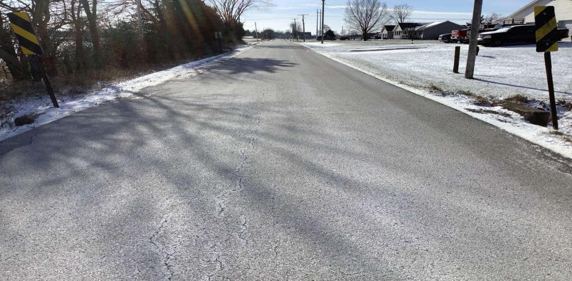
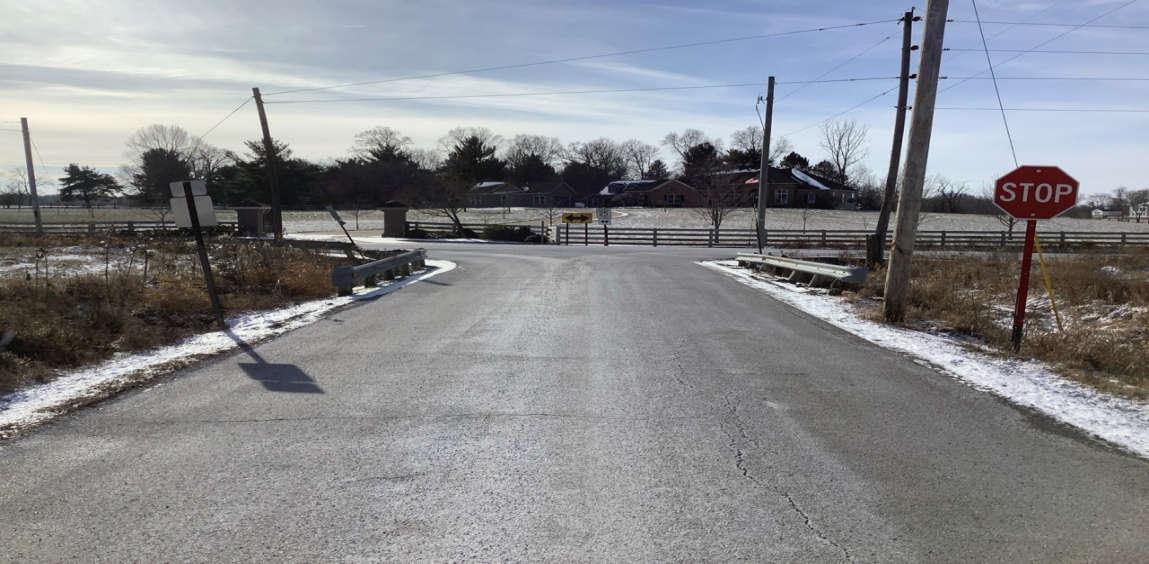
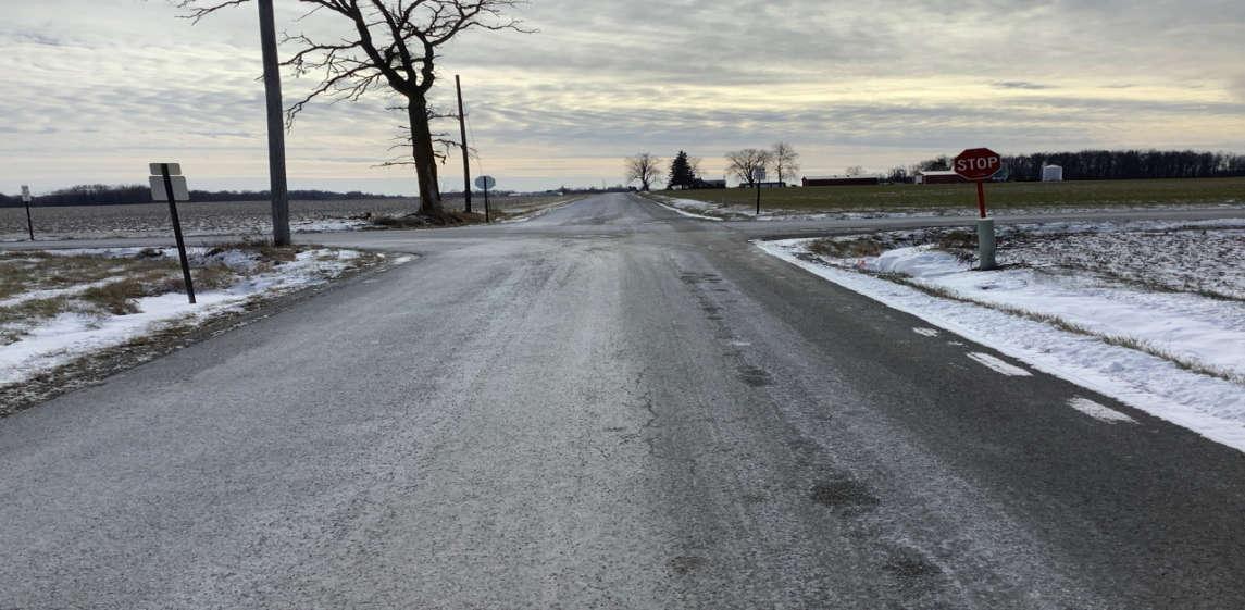
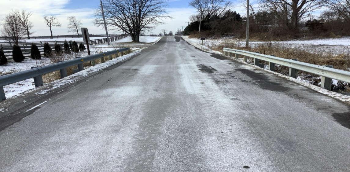
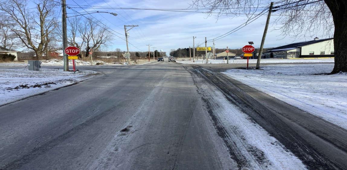
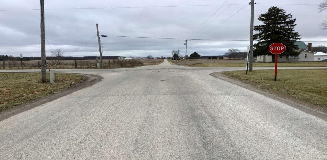
PHOTO 15: Intersection of C-166 and C-25, looking south.
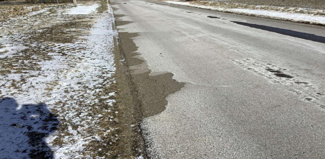
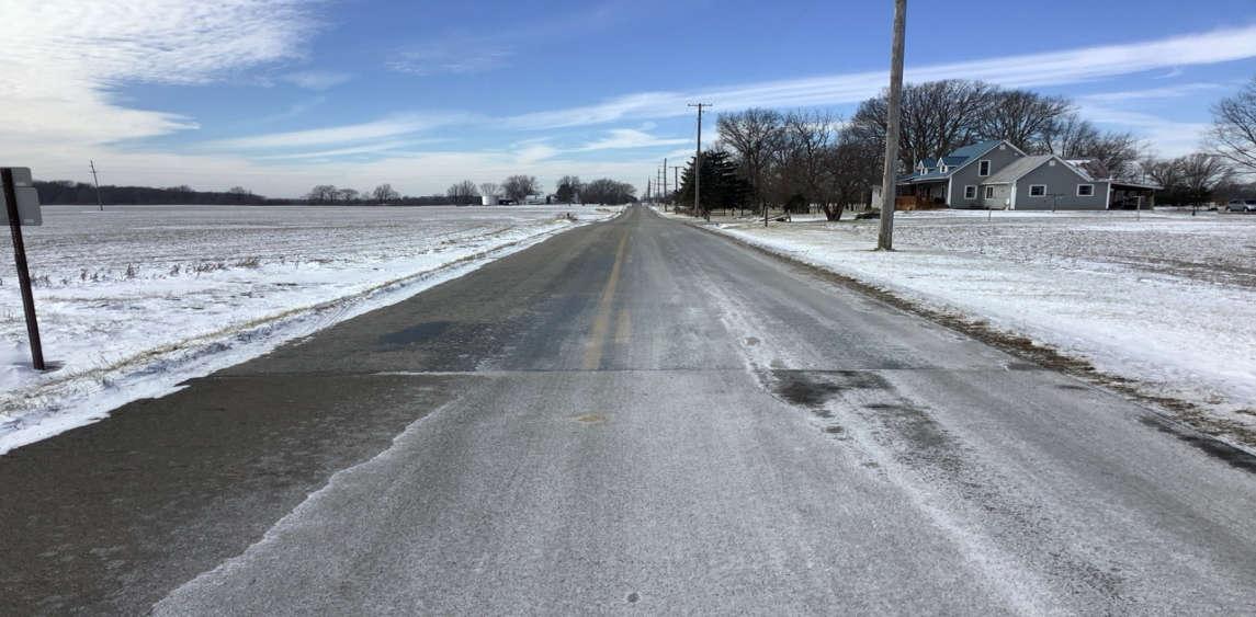
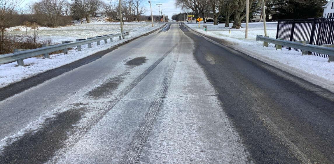
PHOTO 16: Pavement distress (surface wearing, bleeding, minor rutting) on T-25, looking east.
Project Number: 17078
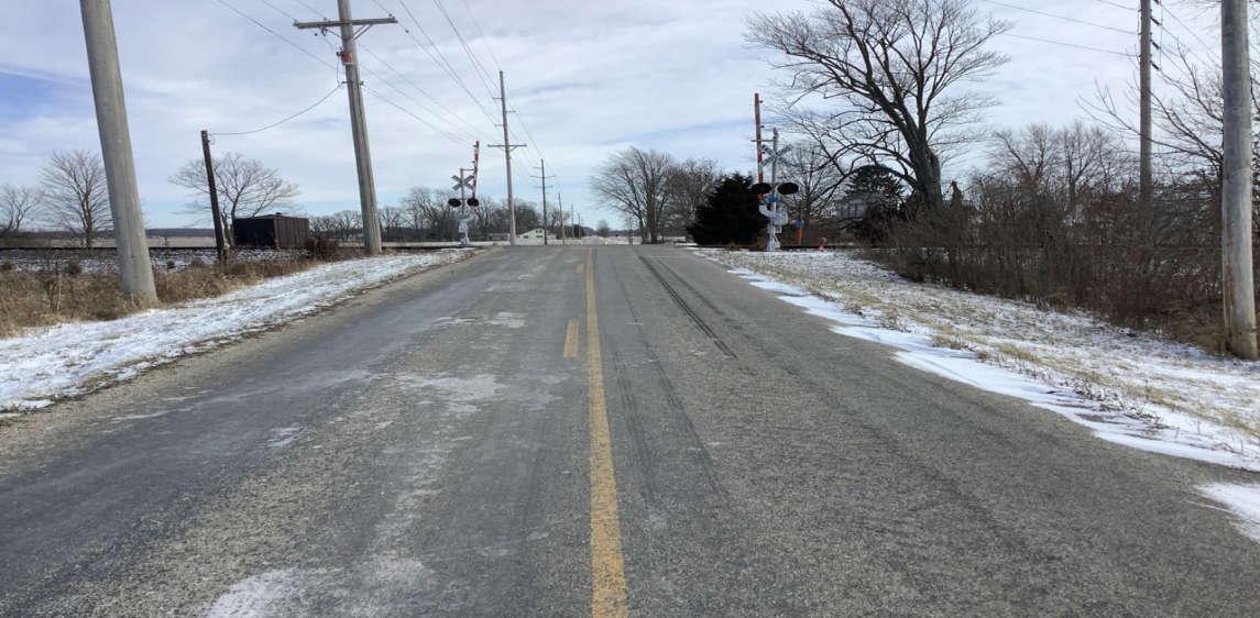
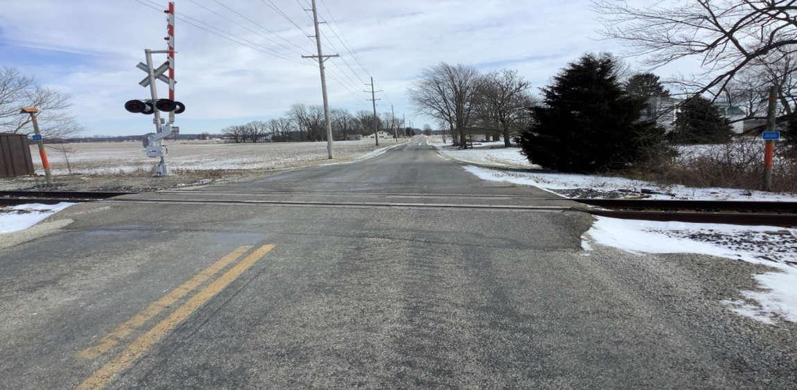
PHOTO 17: Railroad crossing approach on T-25, looking east.
PHOTO 18: Railroad crossing on T-25, looking east.
Crossroads Solar Grazing Center
Transportation Assessment
Roadway Photographs
Morrow County, Ohio
Date Taken:
January 2024
Project Number: 17078
File Name:
17078.0001.XLSX
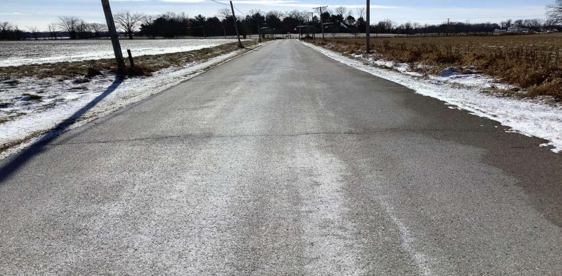
PHOTO 19: End C-25 and begin T-25, looking west.
PHOTO 20: Intersection of C-165 and C-25, looking south.

Crossroads Solar Grazing Center
Transportation Assessment
Roadway Photographs
Morrow County, Ohio
Date Taken:
January 2024
Project Number: 17078
File Name:
17078.0001.XLSX
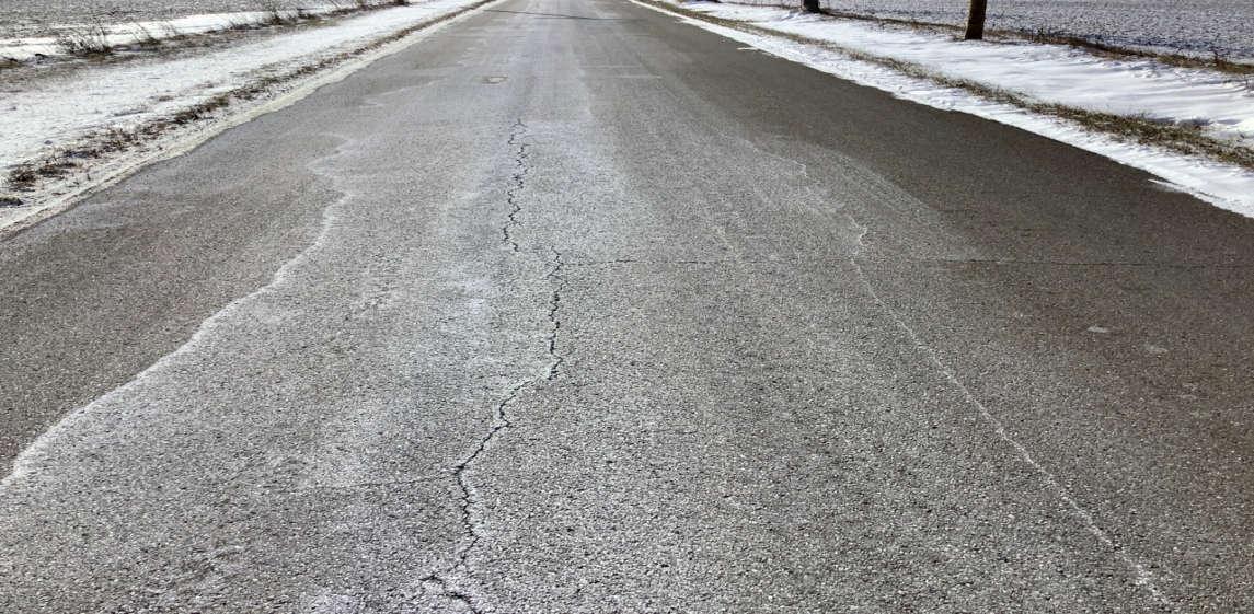
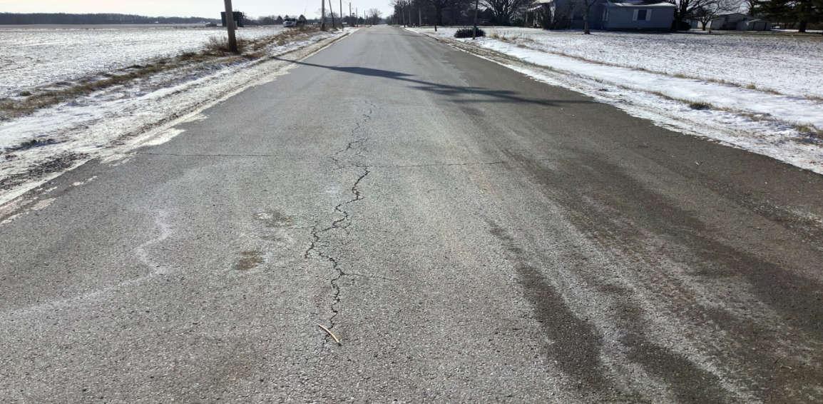
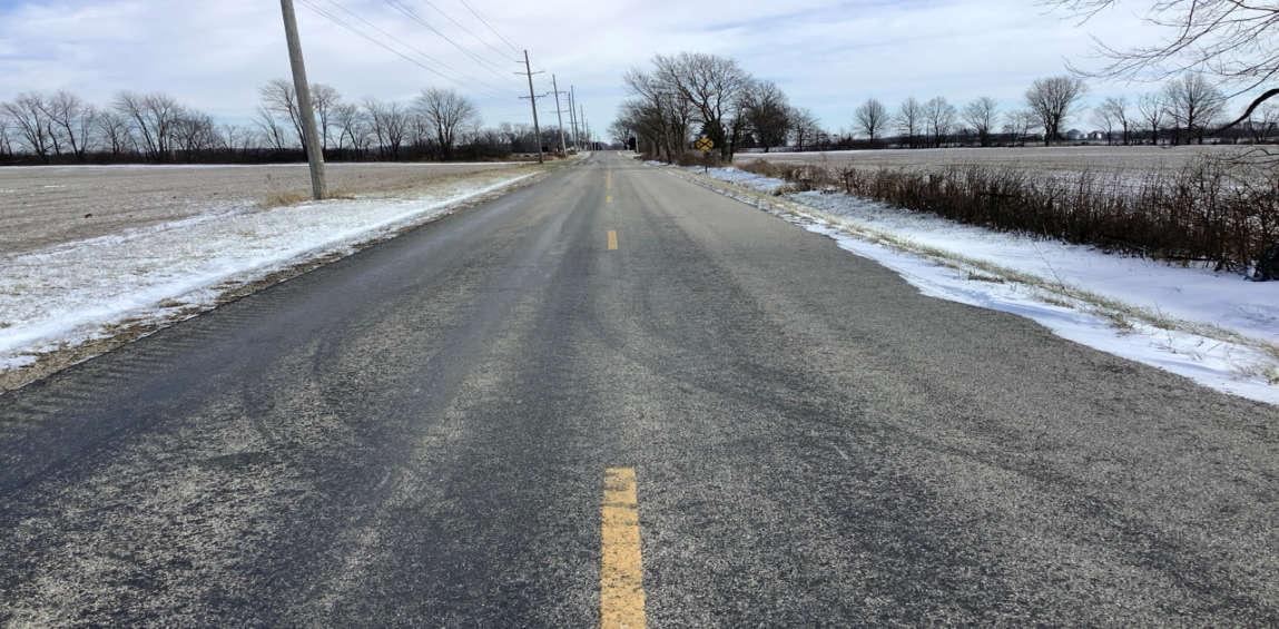
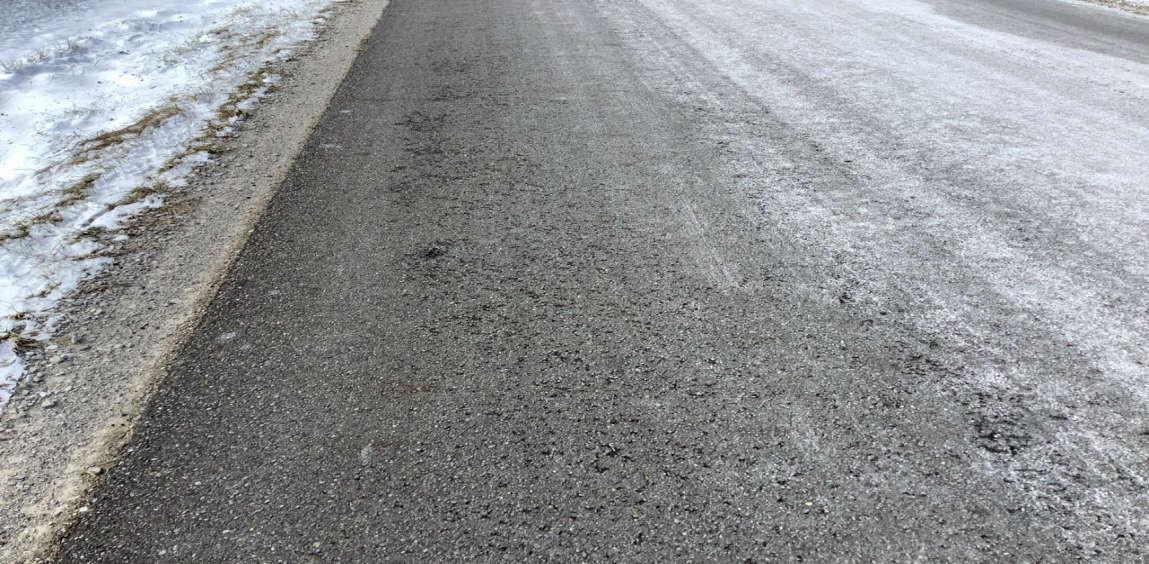
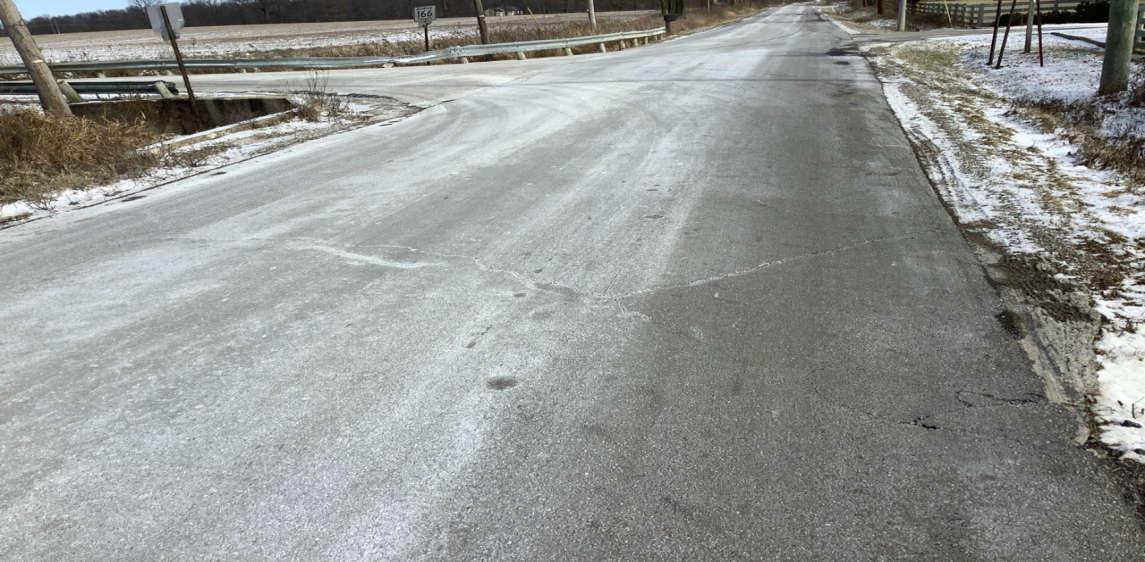
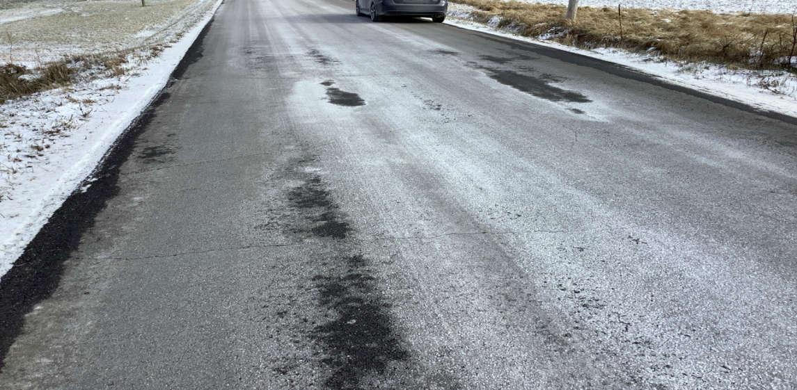
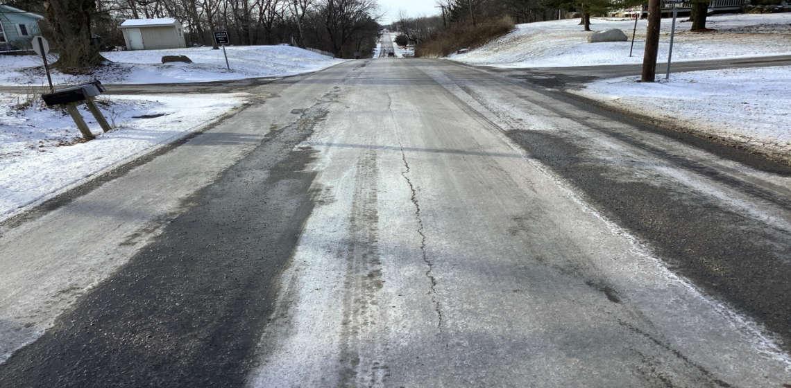
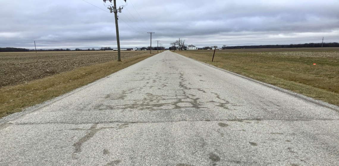
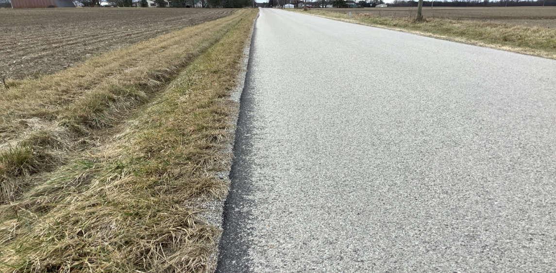
PHOTO 21: Pavement distress (surface wear and minor raveling) on C-25, looking west.
PHOTO 22: Bridge 5932297 on C-25, looking northeast.
Crossroads Solar Grazing Center
Transportation Assessment
Roadway Photographs
Morrow County, Ohio
Date Taken:
January 2024
Project Number: 17078
File Name:
17078.0001.XLSX
PHOTO 23: Bridge 5932297 on C-25, east abutment, looking northeast.
PHOTO 24: Bridge 5932297 on C-25, looking southwest.
Date Taken:
Crossroads Solar Grazing Center
Transportation Assessment
Roadway Photographs January 2024
Project Number: 17078
File Name:
Morrow County, Ohio
17078.0001.XLSX
PHOTO 25: Bridge 5932297 on C-25, west abutment, looking southwest.
PHOTO 26: Pavement distress (longitudinal cracking, edge cracking with minor spalling) over Bridge 5932297 on C-25, looking west.
Crossroads Solar Grazing Center
Transportation Assessment
Roadway Photographs
Morrow County, Ohio
Date Taken:
January 2024
Project Number: 17078
File Name:
17078.0001.XLSX
PHOTO 27: HDPE culvert on C-25, looking northeast.
PHOTO 28: Pavement distress (transverse cracking) over HDPE culvert on C-25, looking east.
Crossroads Solar Grazing Center
Transportation Assessment
Roadway Photographs
Morrow County, Ohio
Date Taken:
January 2024
Project Number: 17078
File Name:
17078.0001.XLSX
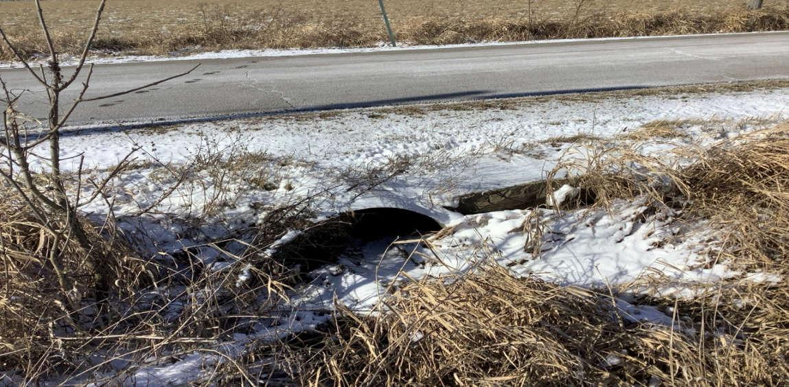
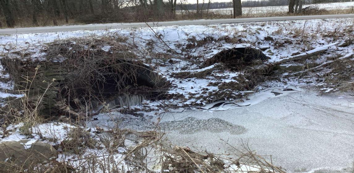
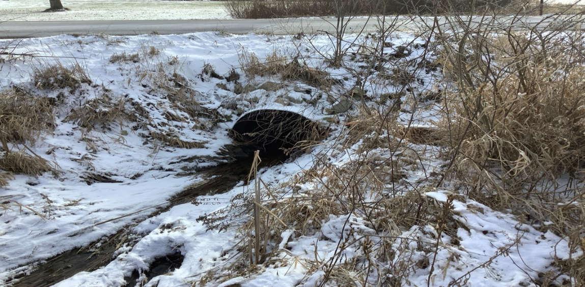
PHOTO 29: Dual CMP culvert on C-25, north inlets partially blocked by debris, looking south.
PHOTO 30: Pavement distress (transverse cracking) over dual CMP culvert on C-25, looking northwest.
Crossroads Solar Grazing Center
Transportation Assessment
Roadway Photographs
Morrow County, Ohio
Date Taken:
January 2024
Project Number: 17078
File Name:
17078.0001.XLSX
PHOTO 31: HDPE culvert on C-25, looking south.
PHOTO 32: Pavement distress (transverse cracking) over HDPE culvert on C-25, looking east.

Crossroads Solar Grazing Center
Transportation Assessment
Roadway Photographs
Morrow County, Ohio
Date Taken:
January 2024
Project Number: 17078
File Name:
17078.0001.XLSX
PHOTO 33: Dual CMP culvert on C-25, looking south.
PHOTO 34: Pavement distress (transverse cracking) over dual CMP culvert on C-25, looking west.
Date Taken:
Crossroads Solar Grazing Center
Transportation Assessment
Roadway Photographs
Morrow County, Ohio
Project Number: 17078
File Name: January 2024
17078.0001.XLSX
PHOTO 35: HDPE culvert on C-25, looking south.
PHOTO 36: Pavement distress (concrete patch with edges cracking/deteriorating) over HDPE culvert on C-25, looking east.

Crossroads Solar Grazing Center
Roadway Photographs
Date Taken:
File Name: Transportation Assessment
January 2024
Project Number: 17078
Morrow County, Ohio 17078.0001.XLSX
PHOTO 37: Bridge 5934702 on C-25, looking northeast.
PHOTO 38: Bridge 5934702 on C-25, west abutment, looking west.

Crossroads Solar Grazing Center
Transportation Assessment
Roadway Photographs
Date Taken:
January 2024
Project Number: 17078
File Name:
Morrow County, Ohio 17078.0001.XLSX
PHOTO 39: Bridge 5934702 on C-25, west abutment, looking west.
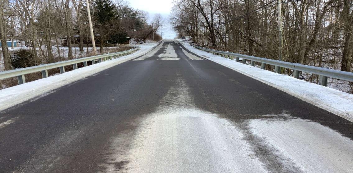
PHOTO 40: Pavement distress (transverse cracking) over Bridge 5934702 on C-25, looking east.

Crossroads Solar Grazing Center
Transportation Assessment
Roadway Photographs
Morrow County, Ohio
Date Taken:
January 2024
Project Number: 17078
File Name:
17078.0001.XLSX
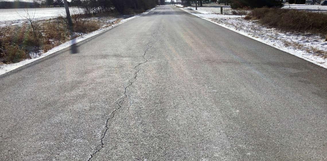
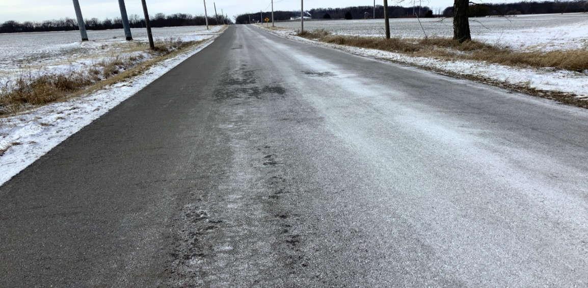
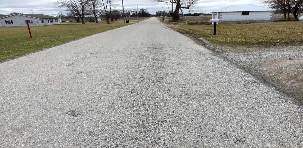
PHOTO 41: Pavement distress (longitudinal cracking) on C-25, looking west.
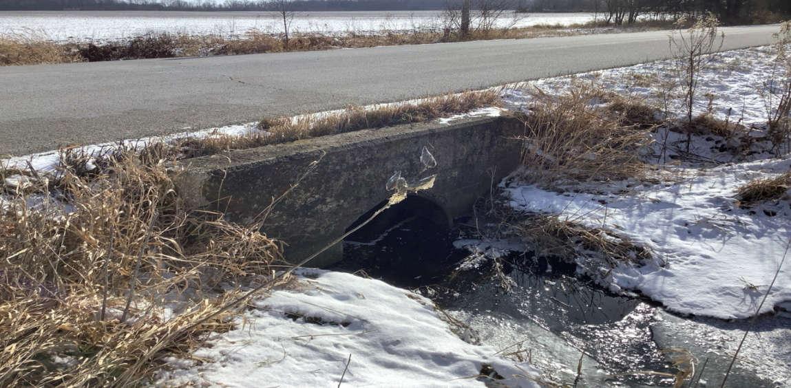
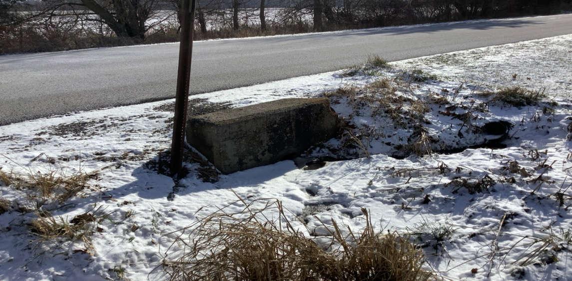
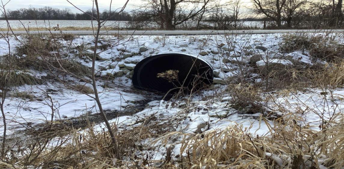
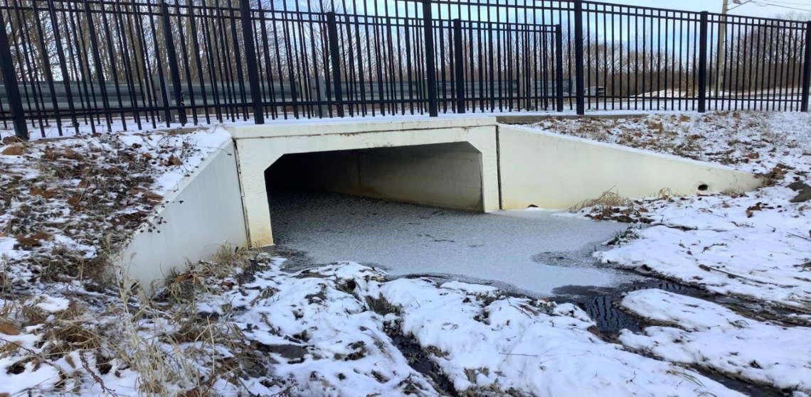
PHOTO 42: Concrete box culvert on C-25, looking northeast.

Crossroads Solar Grazing Center
Transportation Assessment
Roadway Photographs
Morrow County, Ohio
Date Taken:
January 2024
Project Number: 17078
File Name:
17078.0001.XLSX
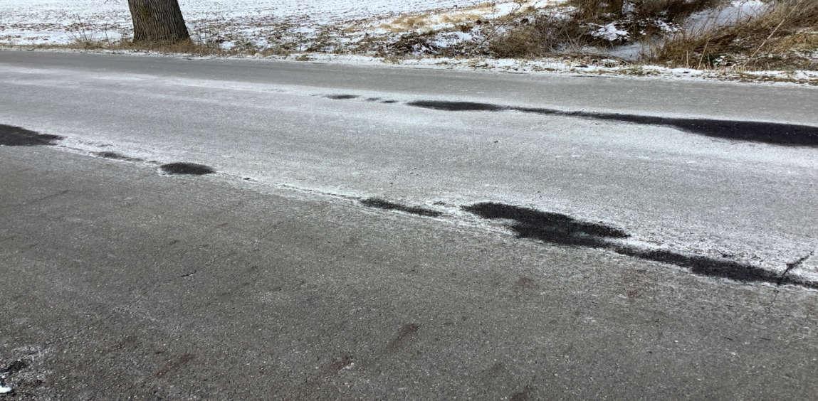
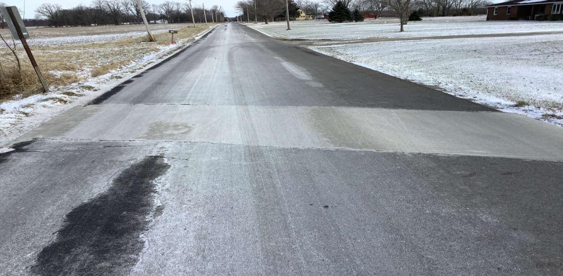
PHOTO 43: Pavement distress (transverse cracking) over concrete box culvert on C-25, looking east.
PHOTO 44: Intersection of C-25 and SR-61, looking east.
Crossroads Solar Grazing Center
Date Taken:
February 2024 Transportation Assessment
Roadway Photographs
Morrow County, Ohio
Project Number: 17078
File Name:
17078.0001.XLSX
PHOTO 45: Intersection of C-155 and C-165, looking east.
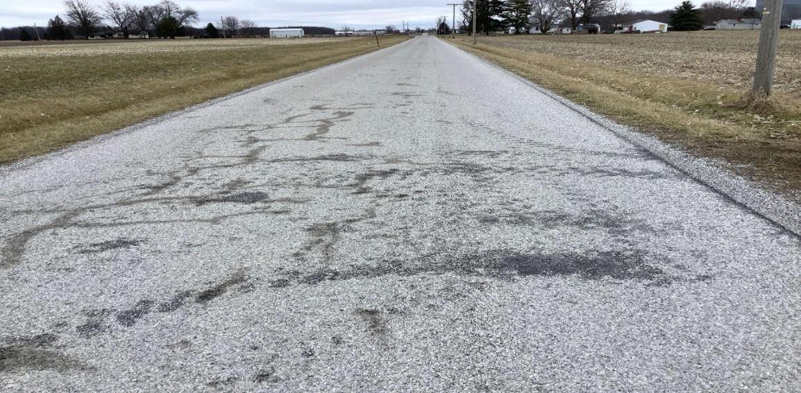
PHOTO 46: Pavement distress (sporadic cracking) on C-155, looking west.

Crossroads Solar Grazing Center
Transportation Assessment
Roadway Photographs
Date Taken:
February 2024
Project Number: 17078
File Name:
Morrow County, Ohio 17078.0001.XLSX
PHOTO 47: Pavement distress (raveling, sporadic cracking) on C-155, looking east.
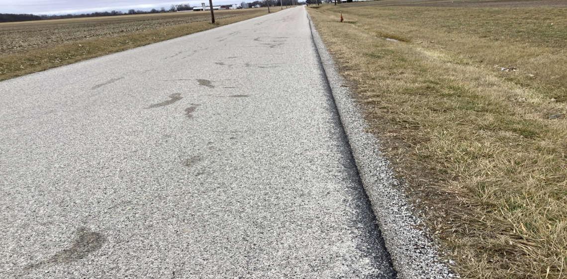
PHOTO 48: Pavement distress (loss of surface aggregate along edges) on C-155, looking west.

Crossroads Solar Grazing Center
Transportation Assessment
Roadway Photographs
Date Taken:
February 2024
Project Number: 17078
File Name:
Morrow County, Ohio 17078.0001.XLSX
PHOTO 49: CMP culvert on C-155, pipe bent slightly out of round, looking north.
PHOTO 50: Pavement distress (transverse cracking) over CMP culvert on C-155, looking north.

Crossroads Solar Grazing Center
Transportation Assessment
Roadway Photographs
Date Taken:
February 2024
Project Number: 17078
File Name:
Morrow County, Ohio 17078.0001.XLSX
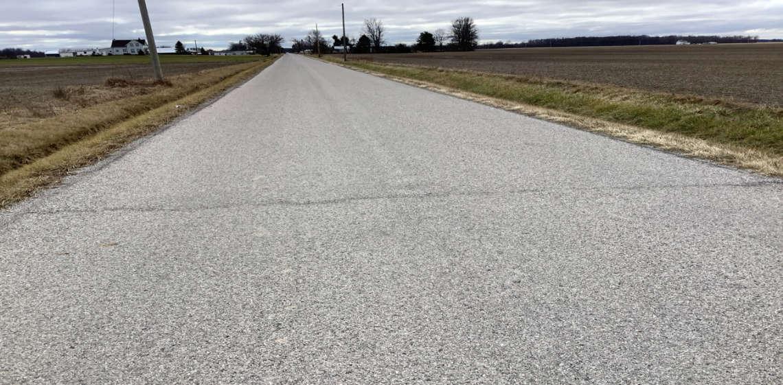
PHOTO 51: Pavement distress (longitudinal cracking) on C-155, looking west.
PHOTO 52: Pavement distress (rough/pitted area forming pothole) on C-155, looking east.
Crossroads Solar Grazing Center
Transportation Assessment
Roadway Photographs
Date Taken:
February 2024
Project Number: 17078
File Name:
Morrow County, Ohio 17078.0001.XLSX
PHOTO 53: Pavement distress (edge deterioration) on C-155, looking west.
PHOTO 54: HDPE culvert on C-155, looking south.
Date Taken:
Crossroads Solar Grazing Center February 2024
Transportation Assessment
Roadway Photographs
Project Number: 17078
File Name: Morrow County, Ohio 17078.0001.XLSX
PHOTO 55: Pavement distress (transverse cracking) over HDPE culvert on C-155, looking east.
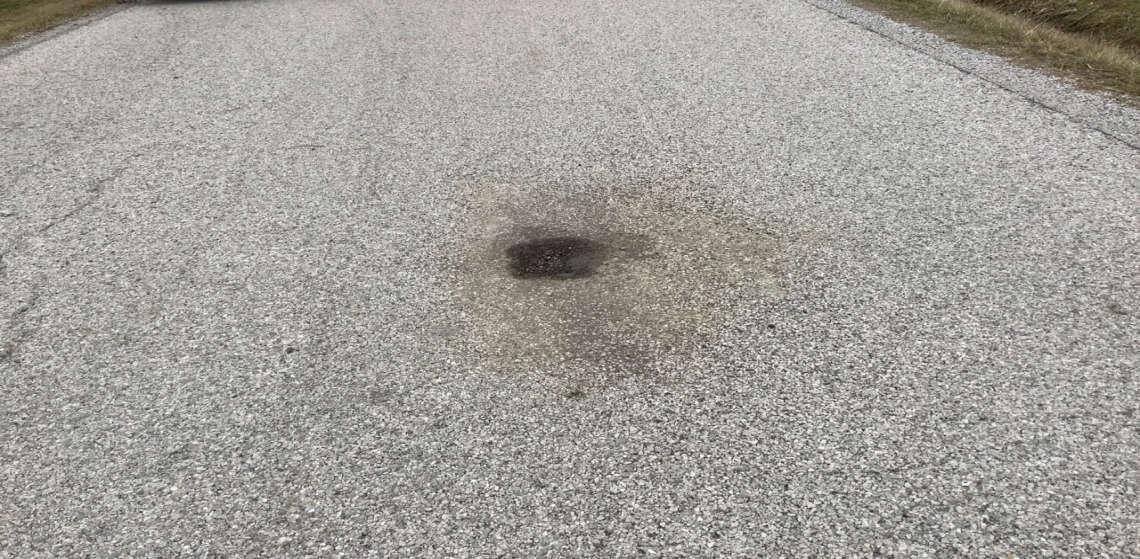
PHOTO 56: Pavement distress (rough/pitted areas forming potholes) on C-165, looking north.
Crossroads Solar Grazing Center
Transportation Assessment
Roadway Photographs
Morrow County, Ohio
Date Taken:
February 2024
Project Number: 17078
File Name:
17078.0001.XLSX
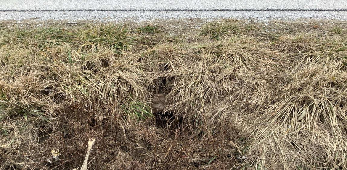
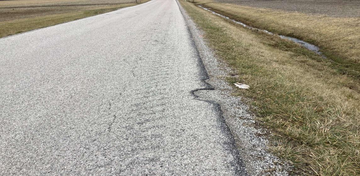
PHOTO 57: Pavement distress (loss of surface aggregate along edges) on C-165, looking south.
PHOTO 58: Pavement distress (raveling, surface wear) on C-165, looking south.
Crossroads Solar Grazing Center
Transportation Assessment
Roadway Photographs
Morrow County, Ohio
Date Taken:
February 2024
Project Number: 17078
File Name:
17078.0001.XLSX
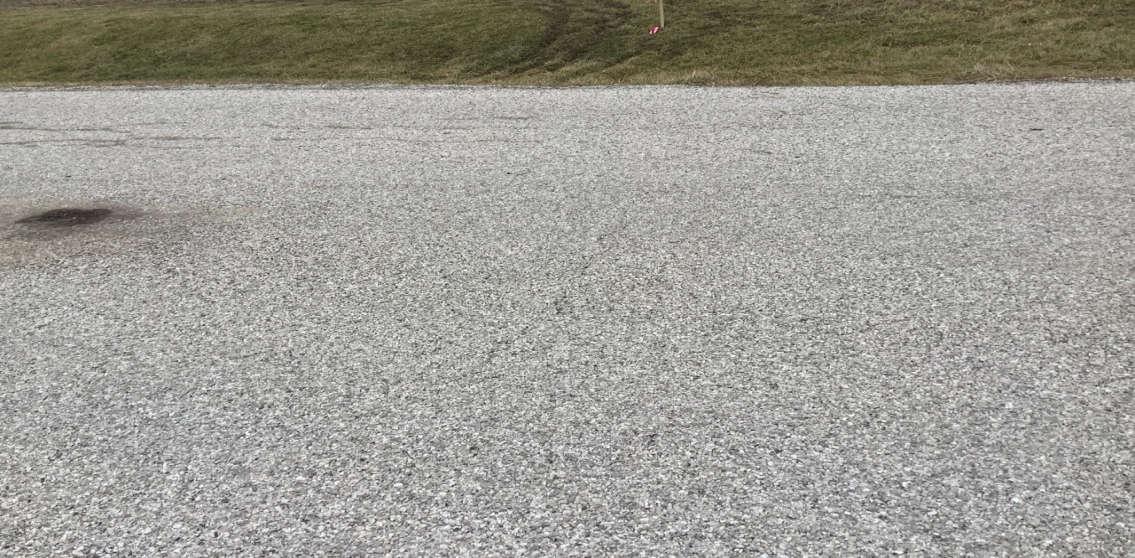
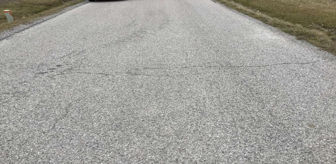
PHOTO 59: Pavement distress (transverse crack) on C-165, looking south.
PHOTO 60: Pavement distress (edge cracking) on C-165, looking south.
Crossroads Solar Grazing Center
Transportation Assessment
Roadway Photographs
Morrow County, Ohio
Date Taken:
February 2024
Project Number: 17078
File Name:
17078.0001.XLSX
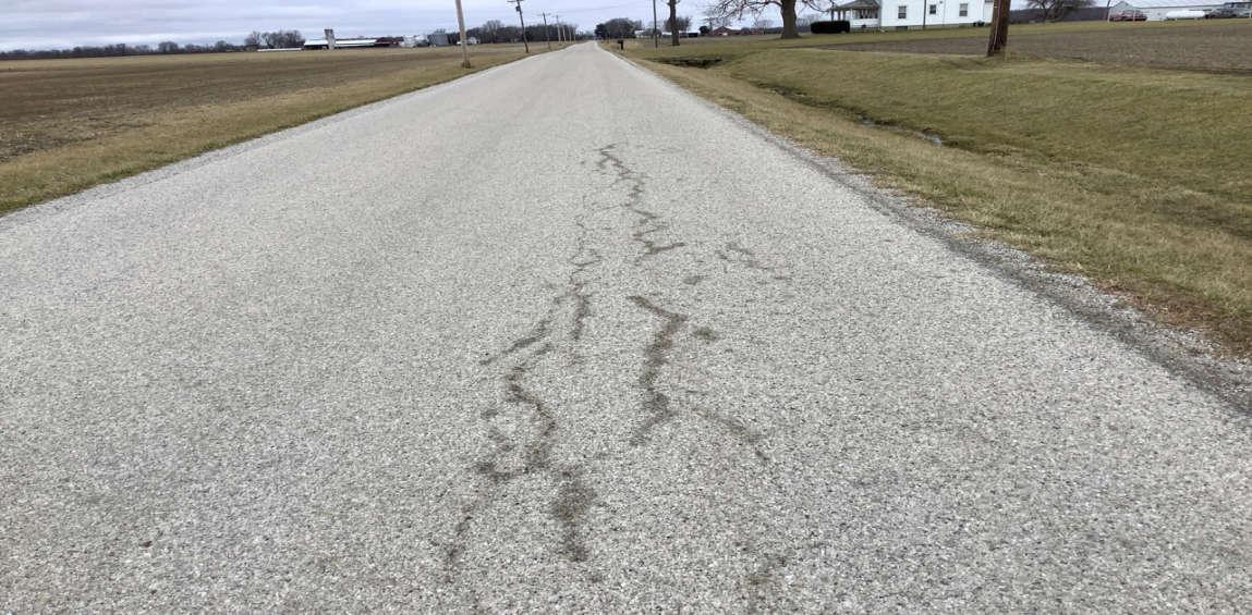
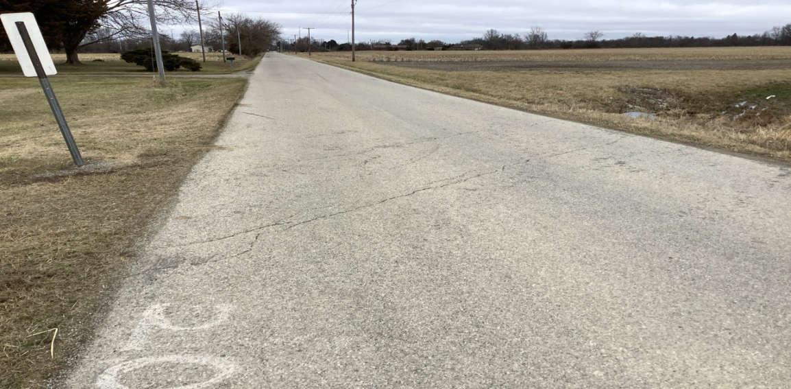
PHOTO 61: Pavement distress (sporadic cracking) on C-165, looking south.
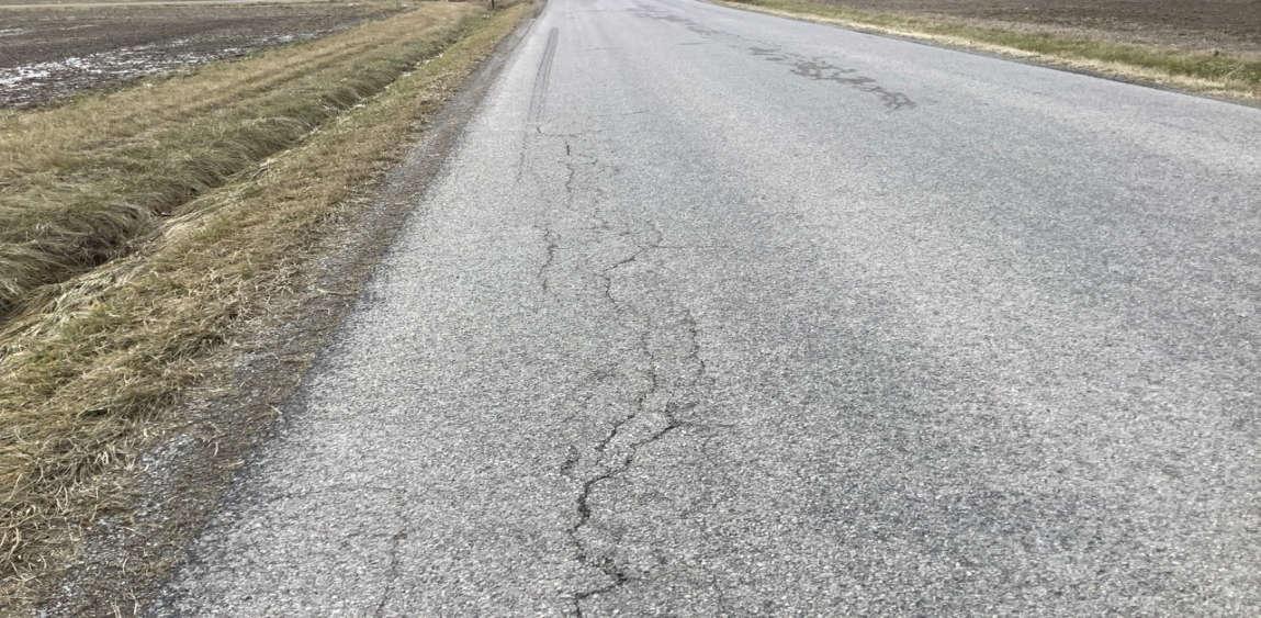
PHOTO 62: Pavement distress (longitudinal cracking) on C-165, looking south.
Crossroads Solar Grazing Center
Transportation Assessment
Roadway Photographs
Date Taken:
February 2024
Project Number: 17078
File Name: Morrow County, Ohio
17078.0001.XLSX
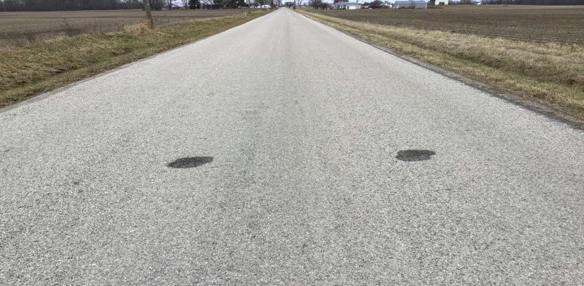
PHOTO 63: Pavement distress (old repair area with surface wear, raveling, sporadic cracking) on C-165, looking north.
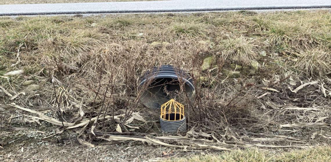
PHOTO 64: Dual CMP culvert on C-165, minor pipe corrosion, looking east.

Crossroads Solar Grazing Center
Transportation Assessment
Roadway Photographs
Morrow County, Ohio
Date Taken:
February 2024
Project Number: 17078
File Name:
17078.0001.XLSX
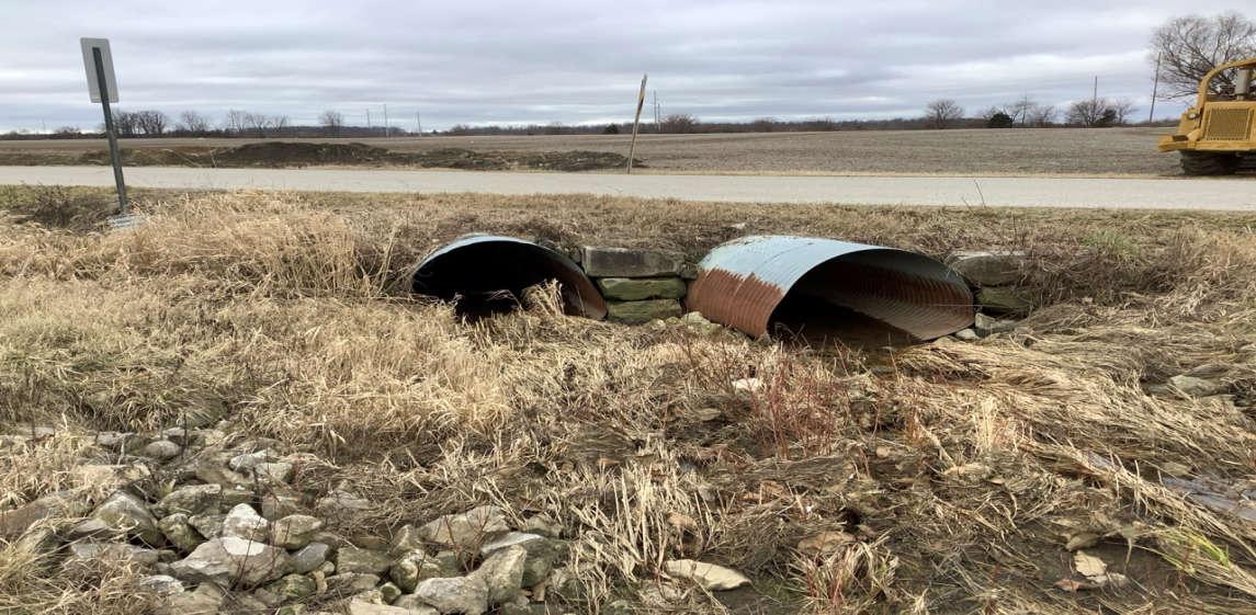
PHOTO 65: Dual CMP culvert on C-165, minor pipe corrosion and pipes out of round, looking west.
PHOTO 66: Pavement distress (transverse cracking) over dual CMP culvert on C-165, looking north.