EXHIBIT EE Agricultural Soils Protection Plan
APPLICATION TO THE OHIO POWER SITING BOARD FOR A
CERTIFICATE OF ENVIRONMENTAL COMPATIBILITY AND PUBLIC NEED FOR THE
Case No. 24-0801-EL -BGN


APPLICATION TO THE OHIO POWER SITING BOARD FOR A
CERTIFICATE OF ENVIRONMENTAL COMPATIBILITY AND PUBLIC NEED FOR THE
Case No. 24-0801-EL -BGN
Grange Solar Grazing Center
Logan County, Ohio
Prepared for:
Grange Solar, LLC
315 E Main Street Russells Point, Ohio 43348
Prepared by:
Verdantas
6397 Emerald Pkwy, Suite 200 Dublin, Ohio 43016 262-707-9092
Verdantas Project No: 15770
September 2024

This page intentionally left blank.

5. References
Figures
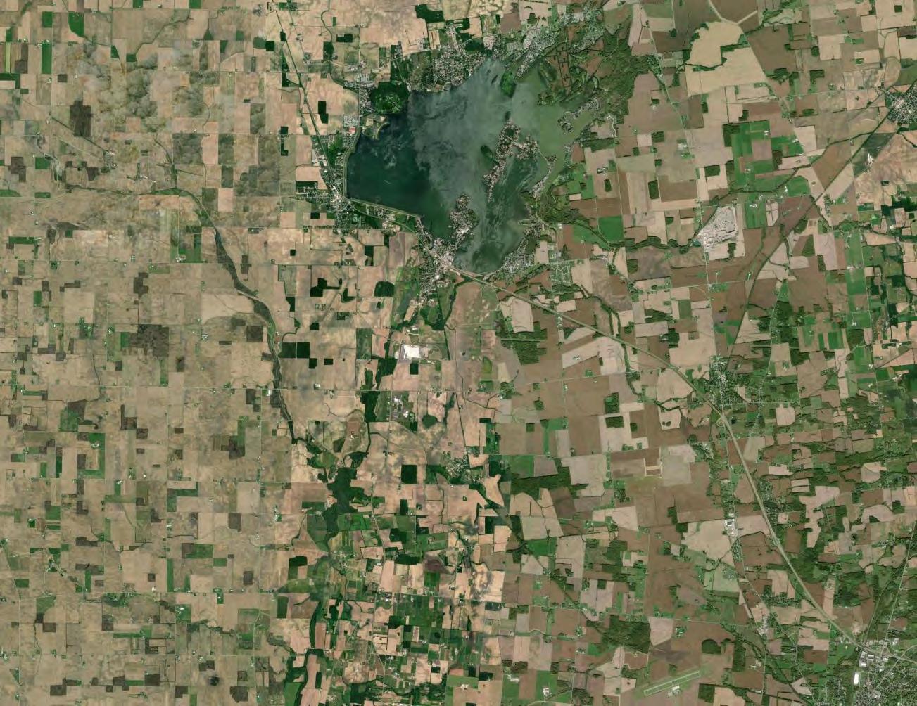
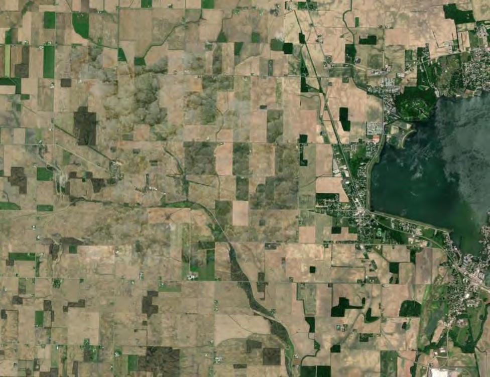
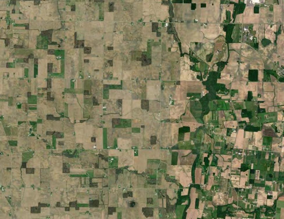
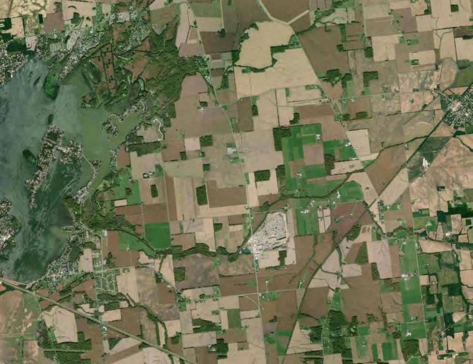
Figure 1 Project Location Map
Figure 2 Physiographic Regions of Ohio
Figure 3 Agricultural Resources Map
Figure 4 Ohio Soil Regions Map
Figure 5 NRCS Soils Map
Figure 6 Agricultural Districts Map
This Preliminary Agricultural Soils Management Plan (Plan) has been prepared for the Grange Solar Grazing Center. The Grange Solar Grazing Center is a combined utility-scale solar energy facility and sheep grazing operation being developed in Logan County, Ohio (the “Project” or the “Facility” or “Grange”). The Project will use rows of ground-mounted solar panels to supply wholesale power to the existing electric grid while also providing pasture for livestock. All of the Project’s above-ground structures will sit within vegetated fields enclosed within agricultural-style fences, which also will confine the livestock and protect them from predators The Project’s aboveground infrastructure will be located within about 2,600 acres of an area totaling approximately 4,100 acres (the “Study Area”; Figure 1).
After construction, sheep grazing is planned as the primary means of vegetation management within the fenced enclosures. Accordingly, the Facility is planned to be revegetated with a coolseason pasture mix to support herds of sheep. Thus, while the Facility is in operation, the land is expected to serve the dual uses of passive energy production and livestock production.
Agricultural soils are a valuable resource in Ohio and of the utmost importance to Grange, the participating landowners, and the local community. Conservation of agricultural soils is needed for the Facility to succeed because of the need to meet stormwater management requirements; to grow forage to support the sheep; and to be able to return the Study Area to agricultural cropland after the Facility is decommissioned.
Most soils in Ohio have been extensively cultivated and altered for agricultural production. Therefore, studying the physical and chemical properties of the soil prior to development activities establishes a soil health and quality baseline that can be used to guide the management of agricultural soils at the Facility. The recommendations and guidance provided in this document were developed with the following primary objectives:
1) Minimize disturbance to agricultural soils within the Study Area during the construction, operation, and decommissioning phases of the Project;
2) Facilitate ground cover establishment for stormwater management and sheep forage;
3) Restore agricultural soils to the original or better conditions upon decommissioning; and
4) Comply with all applicable federal, state, and local regulations.
This Plan, in combination with a preliminary drain tile assessment and a preliminary vegetation management plan provided for the Facility, also is intended to meet certain requirements of OPSB Rule 4906-4-08(E). This Plan is expected to be updated and adapted with Project-specific details as design plans for the Facility are finalized and prior to the start of construction.
Management considerations for the Project are informed by evaluating existing site conditions, planned construction techniques/infrastructure, and Project goals. This section provides an overview of factors that informed the development of this Plan.
This section defines relevant terms used in the discussion of agricultural soils and soil science in this Plan.
Agricultural Soils – A type of soil that is used for the cultivation of crops.
Topsoil – The organically enriched mineral layer or horizon found at the surface of the soil. In soil science, it is referred to as the A horizon, or Ap horizon when found in an agricultural field that is regularly plowed. In agricultural settings, plowing creates a uniform thickness in this horizon, typically 5 to 10 inches deep. The accumulation of organic matter in topsoil results in a darker soil color compared to the color of underlying soil horizons.
Subsoil – The soil material that starts at the bottom of the topsoil, generally to a depth of three feet. Exceptions to this are soils where fractured bedrock or hard bedrock is encountered before three feet.
Soil Health – The capacity of the soil to function as a vital living ecosystem that supports plants, animals, and humans.
Soil Quality – The capacity of a specific kind of soil to perform basic functions such as maintaining vegetative/agricultural productivity, regulating and partitioning of water and solute flow, filtering and buffering against pollutants, and storing and cycling nutrients.
2.2.1
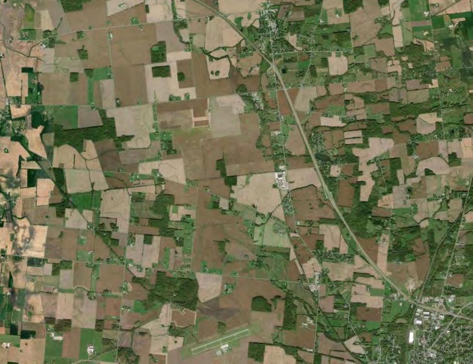
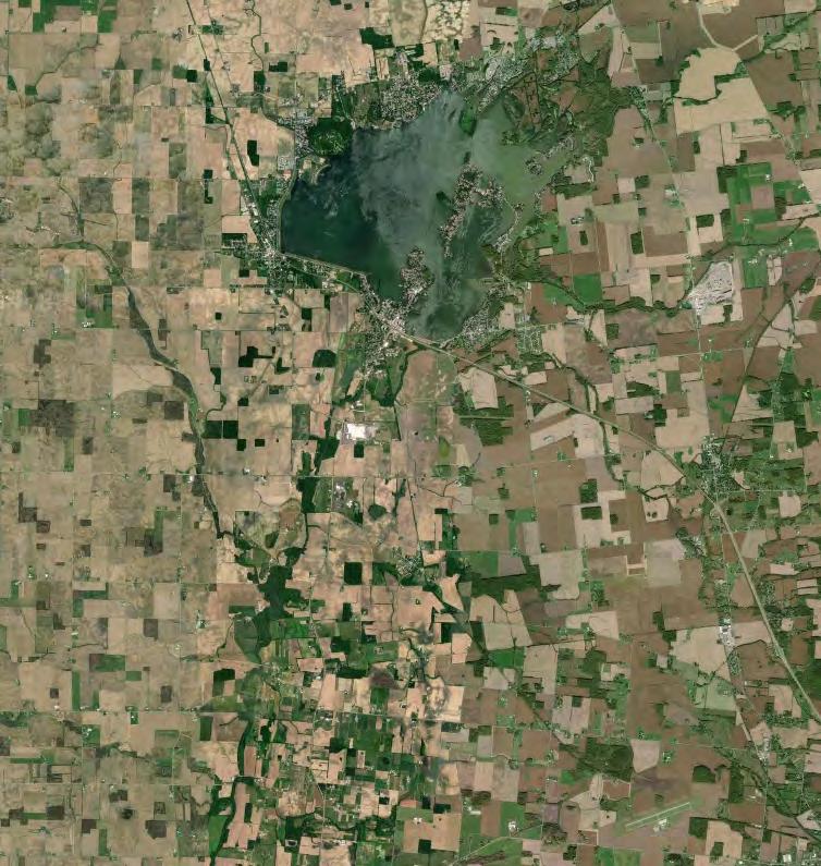
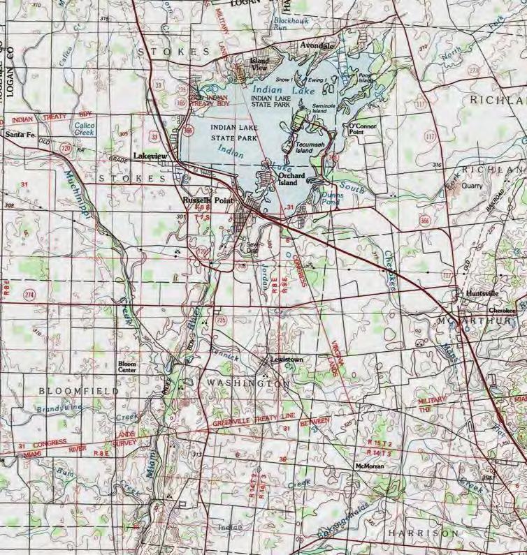
Historical aerial imagery and U.S. Geological Survey (USGS) 7.5-minute topographic quadrangles for Huntsville (1960) and Russells Point (1961) confirm that past land use of the Study Area has been predominantly agricultural. Several gravel pits are shown on the topographic mapping. No other signs of significant soil disturbance, such as mines or major earthworks are shown on the topographic mapping or aerial imagery. Topography within the Study Area is generally flat with minor topographical changes near watercourses.
2.2.2
The Study Area is near the mapped transition between two Physiographic Provinces of Ohio: the Central Ohio Clayey Till Plain and Lake basin/deposits outside Huron-Erie Lake Plains (Ohio Division of Geologic Survey, 1998). The Study Area lies within the Central Ohio Clayey Till Plain. The distinguishing characteristics of the Central Ohio Clayey Till Plain are a surface of high-lime Wisconsinan age clayey till with well-defined moraines with intervening flat-lying ground moraine and intermorainal lake basins (Figure 2). There are no boulder belts There are also approximately a dozen silt-, clay- and till-filled lake basins which range from a few square miles to 200 square miles in area. The Study Area contains few large streams and limited sand and gravel outwash. Elevations within the Central Ohio Clayey Till Plain range from approximately 700 to 1150 feet
above mean seal level (msl) with moderate relief of 100 feet (Ohio Division of Geological Survey, 1998).
The National Land Cover Database (NLCD) confirms the dominant land use within the Study Area is cultivated crops (Table 1; approximately 91% of the Study Area).
Table 1: NLCD Land Cover within the Study Area
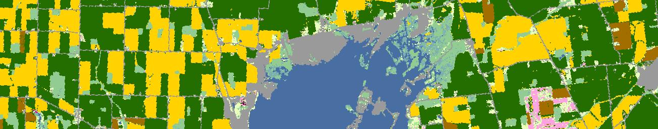
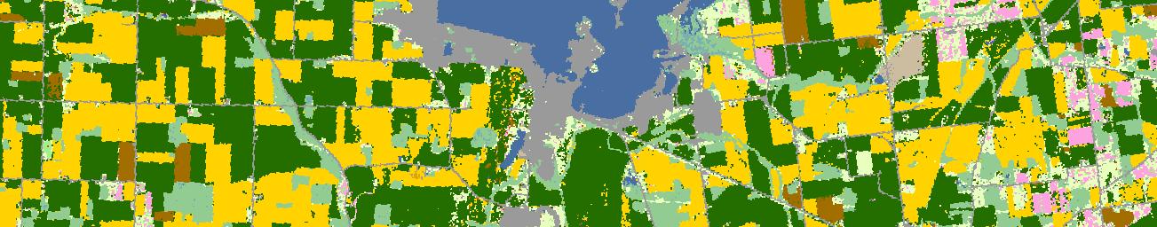
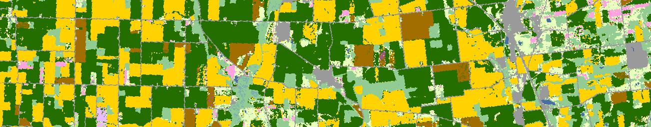
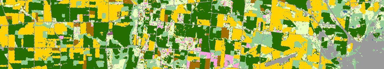
The U.S. Department of Agriculture (USDA) Croplands data layer (CDL) further breaks down landcover into crop types, including major field crops like corn, soybean, cotton, and other specialty crops. The USDA CDL indicates most of the Study Area is sited within areas of soybean and corn, with minor components of the Study Area sited within areas of deciduous forest, developed open space, and grassland/pasture (Figure 3).
Ohio soils generally have been divided into twelve regions based on parent material, glacial history of the State, and land use practices. Soil Regions 1-8 were covered with glacial ice during various glacial events whereas Regions 9-12 are mainly materials weathered from sedimentary rocks. Soils in northwest Ohio (primarily Ohio Soil Region 1) are commonly formed in level environments with less than 8% slopes. Regions 1, 3, 4, 7, and 9 have higher lime content than Regions 2, 5, 6, 8 due to limestone, dolomite, and limy shales that make up a majority of the
bedrock. Regions 10, 11, and 12 soils are formed from weathered sedimentary sandstones, siltstones, and shale
Most of the Study Area is in Soil Region 1 (Hoytville-Nappanee-Paulding-Toledo), and a minor component of the Study Area is in Soil Region 3 (Blount-Pewamo-Glynwood; Figure 4). Soil Region 1 is characterized by poor drainage and high clay content from medium textured lake and beach sediments and glacial till. Soil Region 3 is characterized by medium silt to fine clay glacial till. Soil Regions 1 and 3 have a high lime content in the substratum (OSU, 2024).
National Resources Conservation Service (NRCS) mapping data for Ohio includes site suitability for many land uses, including farmland classifications. Soil map units may be identified as prime farmland, farmland of statewide importance, farmland of local importance, or unique farmland. This classification identifies soils that are best suited for agricultural purposes (the NRCS policy and definitions of prime and unique farmlands can be found in the Federal Register, Vol, 43, No, 21, January 31, 1978)
Twenty-three soil series are mapped within the Study Area according to the NRCS SSURGO database (Figure 5). Surface horizon depths range from 4 to 32 inches within the Study Area. Major soil series (>5% of the total Study Area) include Latty, Fulton, Blount, Wetzel, and Nappanee (Table 2).
Table 2 : NRCS Soil Map Units within the Study Area
Sleeth silt loam, 0 to 2 percent slopes
Blg1B1 Blount silt loam, ground moraine, 2 to 4 percent slopes
Mnl3A Minster silty clay loam, 0 to 1 percent slopes
Shinrock silt loam, 2 to 6 percent slopes
Latty silty clay, occasionally flooded
Lp Lippincott silty clay loam, 0 to 2 percent slopes
Nonhydric
flooding or not frequently flooded during the growing season
Eldean silt loam, 2 to 6 percent slopes
Gwg1B1 Glynwood clay loam, ground moraine, 6 to 12 percent slopes, eroded
Pewamo silty clay loam, 0 to 1 percent slopes
Carlisle muck, Central Ohio clayey till plain, drained, 0 to 2 percent slopes
OcA Ockley silt loam, Southern Ohio Till Plain, 0 to 2 percent slopes
Gwg5C2 Glynwood silt loam, ground moraine, 2 to 6 percent slopes
FlB Fox loam, till plain, 2 to 6 percent slopes
SlA St. Clair silt loam, 6 to 12 percent slopes, moderately eroded
Nonhydric
Nonhydric
DeA Del Rey silt loam, 0 to 2 percent slopes Predominantly Nonhydric
HoB Homer silt loam, 2 to 6 percent slopes Predominantly Nonhydric
ScD2 St. Clair silt loam, 12 to 18 percent slopes, moderately eroded
Gn Genesee silt loam, 0 to 2 percent slopes, occasionally flooded
HoA Homer silt loam, 0 to 2 percent slopes Predominantly Nonhydric
Mns3A Minster silty clay loam, till substratum, 0 to 1 percent slopes
Eldean silt loam, 6 to 12 percent slopes, moderately eroded
SgB St. Clair silt loam, 2 to 6 percent slopes Predominantly Nonhydric
DeB Del Rey silt loam, 2 to 6 percent slopes Predominantly Nonhydric
EmA Eldean silt loam, 0 to 2 percent slopes Predominantly Nonhydric
Approximately 35% of the soils in the Study Area are classified as the very poorly drained Latty series. Latty series is derived from clayey glaciolacustrine sediments and is usually found on lake plains. The typical pedon of this soil has a silty clay textured Ap horizon about 10 inches in depth
Approximately 10% of the soils in the Study Area are classified as the somewhat-poorly-drained Fulton series. Fulton series is derived from clayey glaciolacustrine sediments and is usually found on lake plains. The typical pedon of this soil has a silty clay loam textured Ap horizon about 10 inches in depth.
The somewhat poorly drained Blount series is mapped within approximately 12% of the Study Area Blount series is derived from till and is usually found on wave-worked till plains, till plains, and near-shore zones. The typical pedon of this soil has a silt loam Ap horizon that is about seven inches in depth
The poorly drained Wetzel series is mapped within approximately 9.6% of the Study Area. Wetzel series is derived from clayey till on till plains and moraines and is usually found on lake plains The typical pedon of this soil has a silty clay loam Ap and AB horizon that is about nine inches combined.
The somewhat poorly drained Nappanee series is present within approximately 12% of the Study Area Nappanee series is derived from clayey till and is usually found on wave-worked till plains, till-floored lake plains, till plains, and moraines. The typical pedon of this soil has a clay loam Ap1 and AP2 horizon that is about 10 inches combined
Most of the soil series within the Study Area are designated one of several farmland soil classifications: prime farmland if drained, prime farmland, or farmland of local importance.
Approximately 241 acres (~5.9% of the Study Area) are enrolled as agricultural districts (Figure 6) Agricultural districts must meet two criteria: 1) the land must be used exclusively for agricultural production or used for/qualified for payments or other compensation under a federal land retirement or conservation program, and 2) the property must be greater than 10 acres or produce, on average, an annual gross income of at least twenty-five hundred dollars during a three-year period. Agricultural district status needs to be renewed every five years.
Several related field surveys have been conducted as part of the development of the Project, including surface water delineations; geology/hydrogeology assessments; and archaeological surveys. Each of these surveys included some level of analysis of the soils within the Study Area. Although the scope of these analyses is limited to their respective assessments, some information
is relevant to this Plan. A summary of the soils and vegetation information gathered during each assessment is provided below.
A surface water delineation for the Project identified 20.37 acres of wetlands within the Study Area. According to current regulatory wetland criteria, a wetland must have hydric soils, evidence of inundated or saturated conditions, and a predominance of hydrophytic vegetation. When all three of these criteria are met, a wetland is present and is subject to federal and/or state regulations and permitting. Based on this information, approximately 20.37 acres of soils within the Study Area meet hydric soils indicators. Active cropland (corn and soybeans) dominated the Study Area at the time of field surveys.
A geology/hydrogeology investigation included a reconnaissance of the Study Area to observe conditions including topography, surface geologic features, and surface water conditions. The reconnaissance confirmed a predominance of active agricultural fields, forested riparian corridors, and forested woodlots. Terrain within the Study Area was predominantly flat, consisting of only slight undulation. The subsurface conditions in the vicinity of the proposed solar panel fields were described as surficial agricultural till zone overlying the native soil. The native subsurface conditions were described as moist, medium-stiff to stiff lean clay soils with varying plasticity characteristics and sand fractions. Bedrock was not encountered.
An archaeological survey identified that soils within the Study Area were largely similar throughout. All soil samples taken during this survey contained a plow zone overlaying a subsoil, and no intact, unplowed A-horizon was identified at any of the archaeological sites. The survey confirmed that most of the Study Area was comprised of agricultural land cover.
Impacts to agricultural soils are expected to result from construction, operation, and decommissioning of the Project. Both temporary (construction and decommissioning) and longerlasting (operational) impacts are considered in this assessment, but the focus is on construction, where the vast majority of the impacts are expected to occur.
The amount of land that will be impacted during construction is significantly less than the Study Area itself. Of the 4,100 acres comprising the Study Area, a maximum of about 2,600 acres will host solar panels, above-ground structures, and the sheep grazing operation. Within this smaller area, apart from landscaping and short entrance roads, the land will be impacted by primarily the installation of the following features:
▶ Arrays and support pilings;
▶ Access roads;
▶ Inverters;
▶ Pyranometers;
▶ Collection lines;
▶ Project Substation;
▶ Fencing;
▶ Gen-tie lines; and,
▶ Equipment laydown areas.
A precise breakdown of the potential impacts to agricultural soils by impact type and infrastructure type is provided in the Ecological Impact Assessment prepared for the Project. Construction impacts include trenching for collection lines; ingress/egress/construction pathways for equipment to move throughout the Study Area; equipment laydown areas; and grading. Impacts that will last the life of the Facility include the placement of ground-mounted infrastructure such as support pilings, access roads, inverters, pyranometers, fencing, electrical poles, and substations
Construction activities may result in compaction and potential mixing of topsoil and subsoil. In an agricultural sense, compaction of soil can result in decreased crop yields and increased production costs due to decreased water infiltration, nutrient imbalance, increased soil erosion, and poor aeration. Mixing of topsoil and subsoil can result in similar decreases in crop yields and increased production costs as each soil layer has distinct characteristics and functions that are essential for crop growth Moreover, mixing of soil layers can result in decreased soil health and attempts to re-establish topsoil after-the-fact are costly and intensive. As a result, although construction of a solar facility necessarily will result in widespread soil disturbance at the surface, the focus of this Plan is on measures to minimize compaction, mixing of topsoil and subsoil, and other adverse impacts to agricultural productivity
As noted above, cultivated crops currently comprise the vast majority of the land use in the Study Area. The land is planned to shift primarily from cultivated cropland to pasture for raising sheep for the life of the Project. Where feasible, the Facility is expected to incorporate native flowering forb species to support pollinators (e.g., landscape screening areas outside of the fence line). Refer to the separate preliminary vegetation management plan and preliminary landscape plan prepared for the Project for specific details regarding vegetation that will be part of the Facility.
It is important to remember that row crop farming itself can have both positive and negative impacts to soil Crop roots can help prevent erosion, leguminous crops can add nitrogen to the soil, the remainders of harvested crops can contribute to soil organic matter once decomposed, and rotated crops can help improve soil fertility At the same time, crops can deplete the soils, farm machinery can compact soils, pesticide and herbicide use can have adverse effects on soil health, and intensive agricultural practices can lead to degradation in soil health.
The conversion of cropland to pasture may also result in both positive and negative impacts to soil. Like crops, a mix of cool season grasses and forbs (including legumes) can help prevent erosion, increase soil nitrogen content, and improve soil fertility. Additionally, sheep manure can contribute to soil organic matter, and the action of hooves on soil through rotational grazing can help improve structure and facilitate water infiltration by increasing aeration Compared with growing crops, sheep grazing involves significantly less use of farm machinery (an opportunity to reduce compaction), allows the soil to rest, and requires less pesticide and herbicide use. When sheep are not managed properly, overgrazing can result in the removal of vegetation cover, leading to erosion and soil degradation Likewise, sheep moving over the same areas repeatedly can result in compaction and the accumulation of too much manure can result in soil contamination and nutrient run-off To minimize the potential negative impacts to soils and maximize the potential positive impacts, sheep must be carefully and properly managed The preliminary vegetation management plan and a preliminary grazing plan for the Facility address
best management practices (BMPs) for sheep grazing such as rotational grazing, appropriate stock rates, and managing sheep in unusually wet and unusually dry environmental conditions. Decommissioning of the Project is anticipated to have fewer impacts than construction of the Project. However, some level of soil disturbance is anticipated, primarily in the form of compaction Soils are, however, planned to be restored to, at minimum, pre-construction baseline conditions upon decommissioning.
The following sections describe the steps that Grange is expected to take to manage impacts to agricultural soils during construction, operation, and decommissioning of the Facility. It also contains a number of additional recommendations that could further help manage these impacts.
The Project was designed to disturb the minimum amount of land required to construct the Facility and is expected to adhere to the Ohio EPA Guidance on Post-Construction Stormwater Management for Solar Panel Fields. Stormwater and soils are intricately linked because soil plays a crucial role in regulating the movement of stormwater. Conversely, high levels of stormwater can contribute to soil erosion and soil loss. The guidance sets forth two important goals that are considered in this Plan:
1) Establish a cover of dense, deep-rooting vegetation.
2) Ensure post-construction soils are in good hydrologic condition.
The establishment of cool-season pasture through the steps outlined in the preliminary vegetation management plan is designed to provide forage for sheep while also stabilizing soils and promoting storm water infiltration (also see section below) The BMPs outlined in this Plan are designed to help ensure that post-construction agricultural soils are in good health, including in good hydrologic condition
As described above, land use is anticipated to change from active cropland to active pasture to support flocks of sheep. When practiced correctly, sheep grazing can build soil health and quality over time. Permanent ground cover provides forage for sheep and supports a diversity of plant species in a previously mono-cropped environment (including legumes for nitrogen fixation), decreasing soil erosion and increasing carbon sequestration, water infiltration, and nutrient deposition. Rotational grazing allows for long recovery periods within paddocks, protecting soil from the potential negative impacts associated with sheep grazing. Finally, the deposition of manure on the land, can improve agricultural soils in the long-term.
Project design can minimize the disturbance of agricultural soils by minimizing grading during the construction process. In general, grading is construction earthwork that manipulates the ground’s surface to achieve specific slopes, elevations, and contours. Although it is an essential step in preparing the site for installation of Project infrastructure, earthwork can result in significant disturbance to topsoil and subsoil.
Some construction grading at a utility-scale solar facility is unavoidable, but certain steps can be taken to minimize the need for grading through facility design, such as avoiding areas with significant changes in the land’s natural slope and, if necessary, selecting racking systems with the ability to adapt to moderately changing slopes. Specific measures and any quantification of grading must be based on the final design of the Facility. For the purposes of this Plan, an initial approach to minimizing grading is outlined based on preliminary designs.
The starting point for determining an appropriate degree of grading for any utility-scale solar facility is to precisely define the term “grading.” This is critical to distinguishing the earthwork of concern from the general and more widespread disturbance of the surface that may have far fewer implications for agricultural soil health. Grange has advised that it will use the following definition of grading that was informally developed through consultation between Verdantas, developers of utility-scale solar facilities in Ohio, and staff of the Ohio Department of Agriculture (ODA):
Grading is defined as earthmoving activities incidental to building roads, equipment pads, substations, and laydown yards, installing buried electric lines and drain tile, excavating stormwater basins, performing soil removal activities, soil filling activities, and cut-and-fill activities, but shall not include routine ground disturbance incidental to installing piles, fences, poles for electric lines, vegetation, landscaping, and temporary erosion and sediment controls, performing soil sampling, geotechnical investigations, and archeological investigations, disking topsoil to promote the growth of vegetation, and raking, smoothing ruts, or otherwise creating a smooth and safe work surface.
Given this definition, Grange also has advised that the Project will be designed to minimize grading to a similar extent as recent utility-scale projects approved by OPSB. Specifically, Grange plans to do the following:
(1) Minimize grading to the extent practicable and economically feasible; and,
(2) Seek to achieve a goal of grading no more than 5 percent, but firmly limit grading to no more than 20 percent, of the agricultural lands within the Study Area.
The specific acreage of the agricultural lands within the Study Area that may be subject to grading (as defined above) depends on the selections of key equipment and the final design of the Facility based on those selections. At least 60 days prior to the preconstruction conference, Grange plans to submit a revised version of this Plan with the maximum percentage of the agricultural acreage that will be impacted within the Study Area and, if applicable, the reasons that the percentage is greater than the five-percent goal. This updated plan is expected to also include maps showing the planned areas of grading, the locations of agricultural lands within the Study Area, and planned locations for topsoil storage and/or stockpile areas.
4.2.1
Apart from the minimization of grading, agricultural soils can be responsibly managed during construction of a utility-scale solar facility by adhering to certain BMPs. Grange has advised that it plans to adhere to certain BMPs that were informally developed through consultation between Verdantas, developers of utility-scale solar facilities in Ohio, and staff of the ODA. These BMPs are the following:
(1) Prior to starting grading in a particular location, topsoil shall be removed and stockpiled separate from subsoil.
(2) No stockpiles shall be located in or near drainage ways Stockpiles shall be stabilized in accordance with the Ohio EPA’s NPDES Construction Storm Water General Permit.
(3) Topsoil will remain in the project area.
(4) Topsoil shall not be re-applied to the surface in excessively wet/moist conditions.
(5) For cut-and-fill activities, a profile of the depth and density of the topsoil and subsoil for each area shall be established using representative sampling locations prior to the start of the activity, and a similar profile shall be re-established upon completion of such activity. Topsoil will be removed from the area for which activity is to be performed and separately stockpiled, the subsoil will be excavated and redistributed to lessen the slope, the subsoils will be de-compacted, and then the topsoil will be redistributed over the area.
(6) Existing grassed waterways shall be preserved to the extent practicable. In instances where grassed waterways are to be significantly altered, the Applicant shall submit an analysis that demonstrates how the alteration will not adversely affect drainage of both the project area and neighboring parcels.
(7) Shall sequence construction such that access roads are constructed prior to other grading activities.
(8) Shall instruct construction workers to utilize established access roads and laydown areas for equipment and vehicular traffic, rather than agricultural land, unless installing equipment in the immediate area or as necessary to safely pass other equipment or vehicles.
In addition to the above construction BMPs, the following additional measures could be considered to minimize compaction.
When heavy vehicle and equipment traffic cannot be limited to access roads and designated work areas, soil compaction can be reduced by using low ground pressure equipment. Tracked vehicles are an example of low ground pressure equipment. When possible, keeping vehicles and equipment axle loads at 12,000 pounds or less when soils experience higher than average rainfall for a trailing 30-day period, based on local rainfall data, can also limit compaction.
Soil Moisture Conditions
The presence of high clay content in some Ohio soils results in vulnerability to compaction if heavy equipment is driven during wet conditions. When possible, construction activities should be minimized when soil moisture content is at or near the soil’s field capacity. If soil moisture content is greater than or equal to 75% of the soil’s field capacity moisture content and construction does take place, compaction prevention methods should be used to mitigate impacts. These measures include using tracked equipment, using timber matting, reducing tire pressure, and using floatation tires, doubles, radial tires, or large diameter tires. Methods for simplified field estimates of soil moisture conditions are available in the USDA NRCS publication “Estimating Soil Moisture by Feel and Appearance.”
For most of the Study Area, soil will remain in place during construction, operation, and decommissioning. Some portions of the Study Area, however, will require soil removal during construction or for the life of the Facility. The following are suggestions for stockpiling topsoil so that it can be successfully re-applied.
General Guidelines
If the necessary depth of the excavation will extend below the bottom depth of the topsoil, the topsoil and any subsoil should be segregated into separate piles. Whether the segregation is solely for construction or also for the operation period of the Facility depends on the reason for the excavation. For a utility-scale solar facility such as the Project, some examples of each are as follows:
Construction:
1. Construction Laydown Areas
2. Spot Grading (Cut and Fill)
3. Collection Line Trenching
4. HDD Entrances and Exits
Operation:
1. Access Roads
2. Foundations for Inverters, SCADA Equipment and Project Substation
Construction-only Stockpiling
This type of temporary stockpiling occurs when the topsoil will be replaced during the construction process. For temporary stockpiles, topsoil and subsoil should be placed in two separate and clearly identified stockpiles near the excavated area. Once construction activities are complete, the stockpiled soil should readily be replaced in the order of its original horizonation. Depending on the length of time the stockpiles are needed, seeding and mulching and erosion control practices may need to be conducted in accordance with other plans for the Facility, possibly including the vegetation management plan and the Ohio EPA-required Stormwater Pollution Prevention Plan (SWP3), which must include plans for erosion and sediment control.
Operational Stockpiling
Stockpiles are advised during the operation of the Facility where topsoil is not planned to be replaced until the decommissioning activities. If soil is to be excavated to install infrastructure, separate stockpiles should be created for all displaced topsoil and subsoil to prevent mixing. A
layer of topsoil should be placed over the stockpile to establish vegetative cover. Generally, stockpiling on slopes greater than 15% should be avoided, and no slopes of this severity are expected to be encountered during construction. Seeding and mulching and erosion control practices should be conducted in accordance with the Facility’s vegetation management plan and SWP3.
In addition to the above general guidelines, the following are specific descriptions of typical soil handling practices and recommendations for responsible soil management for the construction of particular features of a utility-scale solar facility, such as the Project
Generally, topsoil is removed from temporary construction laydown areas and stockpiled within the Study Area. Temporary construction laydown areas may require minimal grading of the subsoil to provide proper drainage during construction. Normally a layer of aggregate is placed on the subsoil to provide a wearing surface and protect the subsurface soils. Following construction, the aggregate layer is removed from the Study Area, the subsoils are de-compacted, and the stockpiled topsoil is replaced over the subsoil. Seeding and mulching and erosion control practices should be conducted in accordance with the Facility’s vegetation management plan and SWP3.
For most locations within the Study Area, the solar panel racking will be installed to follow existing topographic contours. In some areas, limited grading (cut and fill) may be necessary to lessen steeper slopes based on the specific model of solar panel racking used for the Project and its associated slope-following tolerance. Where this grading is necessary, topsoil should be removed from the cut-and-fill locations and stockpiled within the Study Area. The subsoil should be excavated and filled to lessen the slope. Following the cut and fill of the subsoil, the subsoils should be de-compacted and the stockpiled topsoil replaced over the subsoil. Seeding and mulching and erosion control practices should be conducted in accordance with the Facility’s vegetation management plan and SWP3.
For collection line trenching, the trench excavation should be performed in two parts to segregate the topsoil from subsurface soils. The topsoil should be excavated first and stockpiled along one side of the trench. Then the subsoil should be excavated and stockpiled along the other side of the trench, separately from the topsoil. After the collection line is installed, the subsoils should be placed back in the trench first, and then the topsoil placed over the subsoil. Some decompaction may be needed. Seeding and mulching and erosion control practices should be conducted in accordance with the Facility’s vegetation management plan and SWP3.
Use of horizonal directional drilling (HDD) does not require extensive excavation of soils. However, some excavation is necessary to connect the collection line from the HDD to a collection line in a trench or where a construction-only excavation along the path of the line is needed. When excavations are performed, topsoil should be removed and stockpiled separately from subsurface soils. Once the excavation is not needed, the stockpiled subsurface soils should be placed in the excavation first and then topsoil placed over the subsoils. Some decompaction may be needed. Seeding and mulching and erosion control practices should be conducted in accordance with the Facility’s vegetation management plan and SWP3.
Topsoil should be removed to create the beds for access road and stockpiled for the life of the Facility within the Study Area. Access roads may require minimal grading of the subsoil to provide proper drainage. Normally a layer of aggregate is placed on the subsoil to provide a wearing surface and protect the subsurface soils. In some locations geotextile fabric and stabilization may be necessary to provide sufficient stability of the road foundation. Temporary and permanent vegetation and mulch should be installed adjacent to the access road on any disturbed soils to establish vegetative cover in accordance with the Facility’s vegetation management plan and SWP3.
Topsoil should be removed from foundation areas for inverters, the SCADA structure and the substation and permanently stockpiled within the Study Area. Foundation areas may require minimal grading of the subsoil to provide a level surface. Normally, a layer of aggregate is placed on the subsoil before the foundation is constructed. Temporary and permanent vegetation and mulch should be installed adjacent to the foundation areas on any disturbed soils to establish vegetative cover in accordance with the Facility’s vegetation management plan and SWP3.
Agricultural soils in the Study Area can be further responsibly managed by determining their preconstruction qualities and planning for a return to at least those qualities during decommissioning. Grange has advised that it plans to implement a comprehensive soil sampling program over the life of the Facility that will generate data needed to determine any necessary soil restoration activities during decommissioning of the Facility. Soil sampling programs such as these were informally developed through consultation between Verdantas, developers of utility-scale solar facilities in Ohio, and staff of the ODA.
Through field sampling and laboratory tests, the baseline conditions of the soil in the Study Area are planned to be determined prior to the start of construction. The components of this testing are as follows:
(1) Implement a program for the collection of baseline data establishing pre-construction soil conditions for the production of row crops for the agricultural areas within the Study Area
(2) Establish the relevant characteristics of both topsoil (defined as the upper most part of the soil commonly referred to as the plow layer, the A layer, or the A horizon, which is typically 5-10 inches in depth in Ohio) and subsoil (defined as the soil material that starts at the bottom of the topsoil, which typically is approximately 36 inches in depth in Ohio, unless fractured or hard bedrock is encountered first).
(3) The baseline data shall be derived from field and laboratory testing of soil conditions; including depth, density and quality from representative locations.
(4) Laboratory testing shall be conducted by an accredited laboratory.
(5) Parameters for assessing soil quality shall include, at a minimum, the following:
a. Infiltration rate
b. Bulk density
c. Water holding capacity
d. pH
e. Percent organic matter
f. Cation exchange capacity
g. Phosphorous/Phosphate (P)
h. Nitrogen (N)
i. Potassium/Potash (K).
Verdantas recommends that the Project implement the above program under the direction of a qualified soil scientist. It is recommended that at least one soil sample be taken as described for approximately every five acres of the Study Area that will be impacted by the final design of the Facility. The soil scientist can use best professional judgement to take additional samples that reflect changes in landform and other factors that may affect soil properties These sampling locations (also referred to as observation points) should be recorded via GPS to enable future resampling efforts in the same locations Beyond the nine quality parameters outlined above, other parameters, such as particle size, could be included at the discretion of the soil scientist.
Soil physical characteristics should be investigated in conjunction with the soil chemical analysis For bulk density, measurements can be collected by using a soil bulk density hammer. Two soil samples per sampling location (the first at 0-2 inches depth and the second at 6-8 inches depth) should be collected. The bulk density samples should be dried and measured according to NRCS bulk density sampling procedures
Soil compaction can be tested using a soil penetrometer at the surface and within the root zone (six inches). The number of penetrometer measurements to be taken should be determined by the discretion of the soil scientist.
The soil sampling program Grange plans to follow also includes an operational element under which the soil quality parameters will be assessed years in advance of decommissioning. Specifically, the program includes the following step:
After 30 years of operation and again after 35 years of operation, soil conditions shall be determined for the same sampling locations using the same parameters and the results used to plan soil restoration activities.
This measure will enable a direct comparison between the baseline conditions and operational soil conditions so that ample time is provided to address any deficiencies ahead of decommissioning. The use of the same sampling locations and the same soil characteristic parameters will enable a matched comparison of results. The results at 30 years also can be used to inform any soil adjustments that should be implemented prior to 35 years.
Establishing and maintaining healthy soil is a gradual and ongoing process that is not amenable to a one-size-fits-all approach. Factors that affect the ability to build soil health include the baseline condition of the soil, the specific practices employed during the operation of the Facility, and the stated goals to be achieved. Thus, Verdantas also recommends periodic monitoring of soil quality and health throughout operation of the Project to help guide the specific restorative practices that may need to occur (i.e. adaptive management measures). Verdantas also recommends that, at the discretion of the soil scientist, soil testing be performed post-construction, but prior to 30 years, to help inform management practices.
At a minimum, Verdantas also recommends that soil health be checked through visual inspections for signs of stressors. Visual inspections would focus on above-ground signs of potential soil stress, including evaluating the health of the vegetation communities; identifying any evidence of erosion or compaction; and signs of ponding Soil samples can also be evaluated subjectively from time to time over the life of the Facility, using the following indicators of topsoil quality that can be useful in identifying areas in need of further investigation:
▶ Soil color: Color can be indicative of minerology and organic matter content. Generally, a change to a darker color implies an increase in organic matter content. A soil color chart (based on the Munsell color system) can be used for evaluating soil color.
▶ Soil structure: Soil structure affects water movement through the soil, along with gas exchange, nutrient cycling, plant rooting, and organism habitat Soil structure, shape and grade can be observed for massive or platy textures due to compaction.
▶ Soil residue cover: This is the percentage of soil surface covered with dead plant material, organic mulch, or live plants.
▶ Residue breakdown: Existing residue cover can be examined for signs of decomposition, shredding, and incorporation by soil organisms. (Note: this should not be assessed soon after mechanical tillage.)
▶ Surface crusting: Surface crusts form on uncovered soil with poor aggregate stability. The presence of surface crusts after rain or irrigation events (and not directly after tillage) should be noted. Crusting may be due to a build-up of salt in the soil, indicating the possible need for additional investigation.
▶ Ponding/infiltration: Surface ponding that occurs after a normal rain event may be due to natural conditions (such as slowly permeable soil layers/textures), or from a soil health concern (compaction).
▶ Penetration resistance: Penetration resistance can be measured when soil moisture is at field moisture capacity (the maximum volume of water that is held by a soil after a rainfall or irrigation event, at the conclusion of free drainage by gravity). Field capacity moisture content differs depending on soil texture. To perform simplified field estimations of soil moisture conditions, refer to the USDA NRCS publication “Estimating Soil Moisture by Feel and Appearance.”
▶ Water-stable aggregates: There are three common methods to test water-stable aggregates: the strainer method, the SQTKG method, and the cylinder method.
▶ Plant roots: Plant roots exude organic compounds that result in the formation of soil structure. Roots within the top 6 or 12 inches of the soil should be abundant and healthy Sideways root growth may indicate restrictive layers and a lack of root hairs may be due to oxygen deprivation.
▶ Biological diversity: Soil organisms influence aggregation, water dynamics, and nutrient cycling The presence of different soil organisms such as fungal hyphae, legume nodules, earthworms, and insects are relevant to soil health
▶ Biopores: A larger sample of soil (e.g., from a shovel instead of a probe) for small holes left from plant roots and organisms should be assessed
If periodic inspections identify potential deficiencies, further soil testing may be needed to diagnose the specific issue. In instances where soils or vegetation do not meet performance criteria, or do not appear on track to meet performance criteria, adaptive management measures/restoration practices may need to be implemented. Verdantas recommends
addressing deficiencies as soon as they are identified to allow ample time for soil health to build prior to decommissioning.
One goal of this Plan is to restore agricultural soils to the original or better conditions upon decommissioning unless otherwise agreed to by the landowner. Activities during decommissioning will be comparable to the construction phase, including the use of heavy equipment on-site, preparing staging areas, and restoring areas that were disturbed during work activities. The removal of infrastructure and restoration of the site should follow the Facility’s decommissioning plan as well as the guidance provided for construction in Section 4.2, where applicable. Construction BMPs as presented in Section 4.2.1 and additional compaction minimization measures as presented in Section 4.2.2 should be followed during decommissioning. The following section describes decommissioning-specific construction activities.
For most of the Study Area, soil will remain in place during decommissioning. Some portions of the Study Area, however, will require temporary soil removal to remove below-ground infrastructure (e.g. certain collection lines). Operational topsoil stockpiles should be redistributed upon removal of all infrastructure.
General Guidelines
If the necessary depth of the excavation will extend below the bottom depth of the topsoil, the topsoil and any subsoil should be segregated into separate piles.
Decommissioning-only Stockpiling
This type of temporary stockpiling occurs when the topsoil will be replaced after removal of the belowground infrastructure is completed. For temporary stockpiles, topsoil and subsoil should be placed in two separate and clearly identified stockpiles near the excavated area. Once decommissioning activities are complete, the stockpiled soil should readily be replaced in the order of its original horizonation. Depending on the length of time the stockpiles are needed, seeding and mulching and erosion control practices may need to be conducted in accordance with other plans for the Facility, possibly including the vegetation management plan and the SWP3
Operational Stockpiling
Operational stockpiles, which were placed during the initial construction phase, are planned to be replaced during decommissioning activities.
4.4.2
Solar Racking Systems, Perimeter Fencing, and in-Array Areas
The removal of solar racking systems, perimeter fencing, and the in-array areas may leave areas that will need backfilling. Operational stockpiles should be respread, and soil should be decompacted Seeding and mulching and erosion control practices should be conducted in accordance with the Facility’s vegetation management plan and SWP3.
Underground Electric Collection Cables
Buried cables within three feet of grade are expected to be removed via trenching. The trench excavation should be performed in two parts to segregate the topsoil from subsurface soils. The topsoil should be excavated first and stockpiled along one side of the trench. Then the subsoil should be excavated and stockpiled along the other side of the trench, separately from the topsoil. After the collection line is removed, the subsoils should be placed back in the trench first, and then the topsoil placed over the subsoil. Some decompaction may be needed. Seeding and mulching and erosion control practices should be conducted in accordance with the Facility’s vegetation management plan and SWP3. Buried cables greater than three feet below grade may be left in place, unless otherwise needed for maintenance or repair of field tile systems.
During decommissioning, unless retained by the land owner, the road aggregate and any geotextile fabric and cement-stabilized soils should be removed from the Study Area. The subsurface soils should be decompacted and the stockpiled topsoil should be replaced over the subsoil. Seeding and mulching and erosion control practices should be conducted in accordance with the Facility’s vegetation management plan and SWP3.
During decommissioning, the equipment, foundations, and any aggregate are expected to be removed from the Study Area. The subsurface soils should be decompacted and the stockpiled topsoil replaced over the subsoil. Seeding and mulching and erosion control practices may need to be conducted in accordance with the Facility’s vegetation management plan and SWP3.
The soil sampling program Grange plans to follow includes a final element that was informally developed through consultation between Verdantas, developers of utility-scale solar facilities in Ohio, and staff of ODA under which soil conditions will be assessed, and any necessary restoration undertaken as part of decommissioning. Specifically, the program includes the following step:
▶ After equipment is removed as part of decommissioning, soil conditions shall be determined for the same sampling locations using the same parameters. Soil restoration activities shall be performed as necessary to return soil conditions to at least baseline conditions. Staff will be provided with data of soil conditions within 30 days after the receipt of results.
As with the operation period sampling and testing, this measure will enable a direct comparison between soil conditions at decommissioning and all prior sampling data. If deficiencies are identified during decommissioning, soil restoration activities should be performed. Possible issues and remedies could include:
▶ If plant-available nutrients are below baseline conditions, additional testing may be needed to verify consistently lower values (rather than seasonal fluctuations) If values remain lower than baseline or are in amounts that are restrictive to plant growth, fertilizer may need to be applied.
▶ Low organic matter: If organic matter is low compared to baseline testing, compost, mulch, or cover crops can help improve moisture retention, nutrient levels, soil fertility, and microbial activity.
▶ Low pH: If tests indicate pH is lower from baseline, lime can be used to adjust and regulate pH conditions Lime neutralizes excess acidity, therefore raising pH and promoting a more favorable range for plant growth.
▶ Soil bulk density increases from baseline: Subsoiling or disking may be needed at decommissioning Bulk density results may be evaluated alongside soil health results to determine whether high values are impacting plant growth (e.g., horizontal root growth and surface crusts).
Restoring soils to at least baseline conditions can be challenging and is dependent on the extent of disturbance and the specific conditions of the soil. First and foremost, Grange seeks to avoid and minimize negative impacts to agricultural soils through appropriate design of the Facility.
In areas where impacts to soils are unavoidable, this Plan provides the steps to responsibly manage agricultural soils such that the land can be returned to agricultural row crop production after the Facility is decommissioned.
Division of Soil and Water Conservation, Ohio Department of Agriculture, Soil of Ohio brochure 2018, Available at: https://agri.ohio.gov/divisions/soil-and-water-conservation/resources/Soil_science
Ohio State University (OSU) Extension, The Ohio State University, Soil Type and History, 2024, Available at: https://soilhealth.osu.edu/soil-health-assessment/soil-type-history
Soil Survey Staff, Natural Resources Conservation Service, United States Department of Agriculture, Official Soil Series Descriptions (OSD), Available at: https://soilseries.sc.egov.usda.gov/
Soil Survey Staff, Natural Resources Conservation Service, United States Department of Agriculture, Web Soil Survey, Available at: http://websoilsurvey.nrcs.usda.gov
U.S, Army Corps of Engineers, 1999, Standard Operating Procedures for the Regulatory Program.
U.S, Army Corps of Engineers, 2010, Regional Supplement to the Corps of Engineers Wetland Delineation Manual: Midwest Region (Version 2.0), ed, J.S, Wakeley, R.W, Lichvar, C.V, Noble, ERDC/EL TR-10-16, Vicksburg, MS: U.S, Army Engineer Research and Development Center.
U.S, Department of Agriculture, Natural Resources Conservation Service, 2018, Field Indicators of Hydric Soils in the United States: A Guide for Identifying and Delineating Hydric Soils, Version 8.2, L.M, Vasilas, G.W, Hurt and J.F, Berkowitz (eds.), USDA, NRCS, in cooperation with the National Technical Committee for Hydric Soils.
U.S, Fish and Wildlife Service (USFWS), 2002, National Wetlands Inventory, U.S, Fish and Wildlife Service, St, Petersburg, FL.
U.S, Geological Survey (USGS), 1975, Topographical quadrangle maps (7.5-minute series), Russells Point and Huntsville, Ohio quadrangles, U.S, Department of the Interior, Washington, D.C.
Figures


DISCLAIMER: Verdantas LLC has furnished this map to the Client for its sole and exclusive use as a preliminary planning and screening tool. This map is reproduced from geospatial information compiled from third-party sources which may change over time and are not accurate as to mapping, surveying or engineering standards. Verdantas LLC makes no representation or warranty as to the content, accuracy, timeliness or completeness of any information. In no event will Verdantas LLC, its owners, officers, employees or agents, be liable for damages of any kind arising out of the use of this map by Client or any other party.