EXHIBIT DD
Drain Tile Assessment
APPLICATION TO THE OHIO POWER SITING BOARD FOR A
CERTIFICATE OF ENVIRONMENTAL COMPATIBILITY AND PUBLIC NEED FOR THE
GRANGE SOLAR GRAZING CENTER
Case No. 24-0801-EL -BGN


APPLICATION TO THE OHIO POWER SITING BOARD FOR A
CERTIFICATE OF ENVIRONMENTAL COMPATIBILITY AND PUBLIC NEED FOR THE
Case No. 24-0801-EL -BGN

Grange Solar Grazing Center
Logan County, OH
Prepared For:
Grange Solar, LLC
315 E. Main Street
Russells Point, OH 43348
Prepared By:
Verdantas LLC
6397 Emerald Parkway, Suite 200 Dublin, Ohio 43016
Verdantas Project No: 15770
September 2024

FIGURES
FIGURE 1
FIGURE 2 to 58
Probable Drain Tile Locations
Probable Drain Tile Mapping

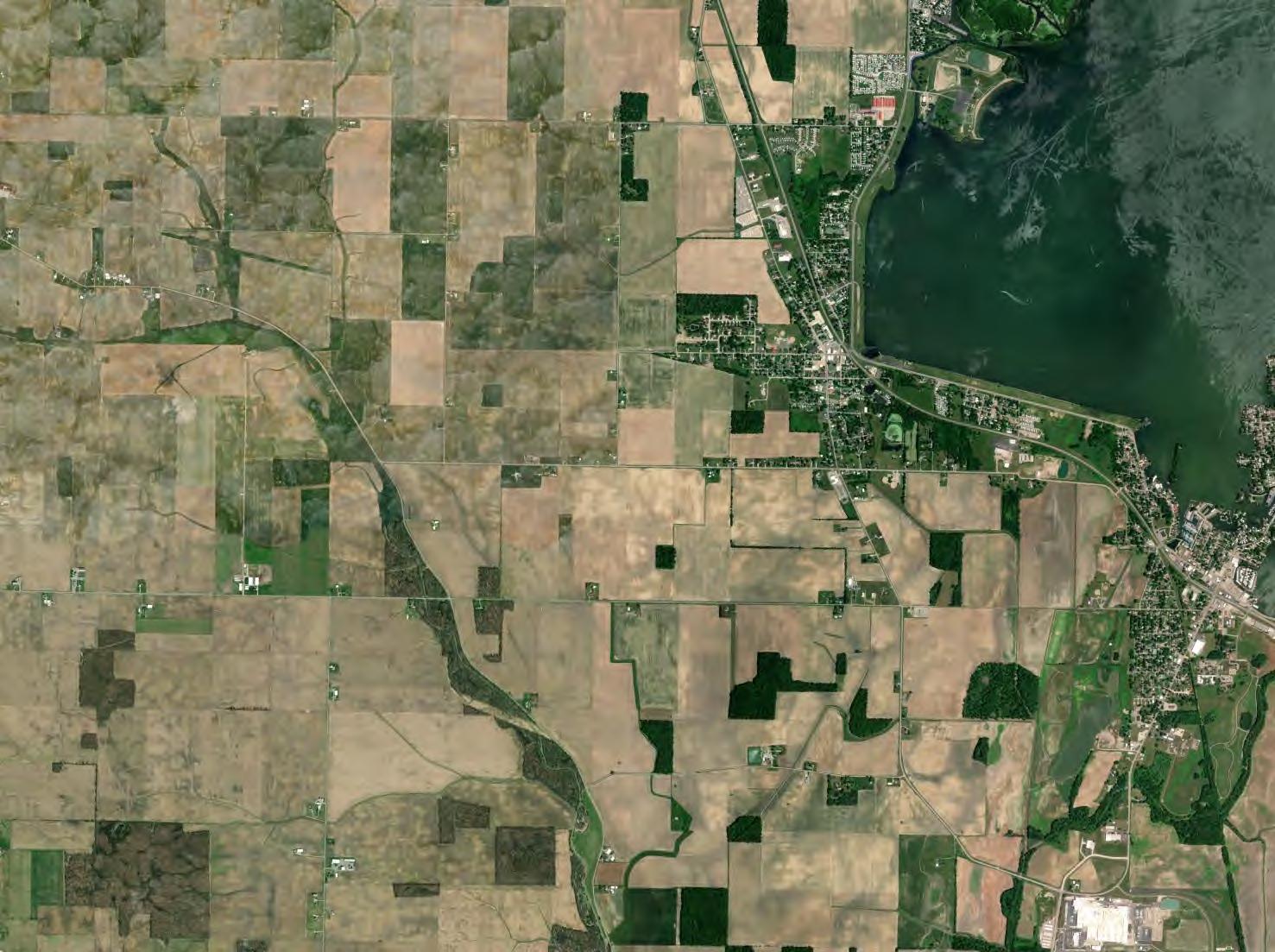
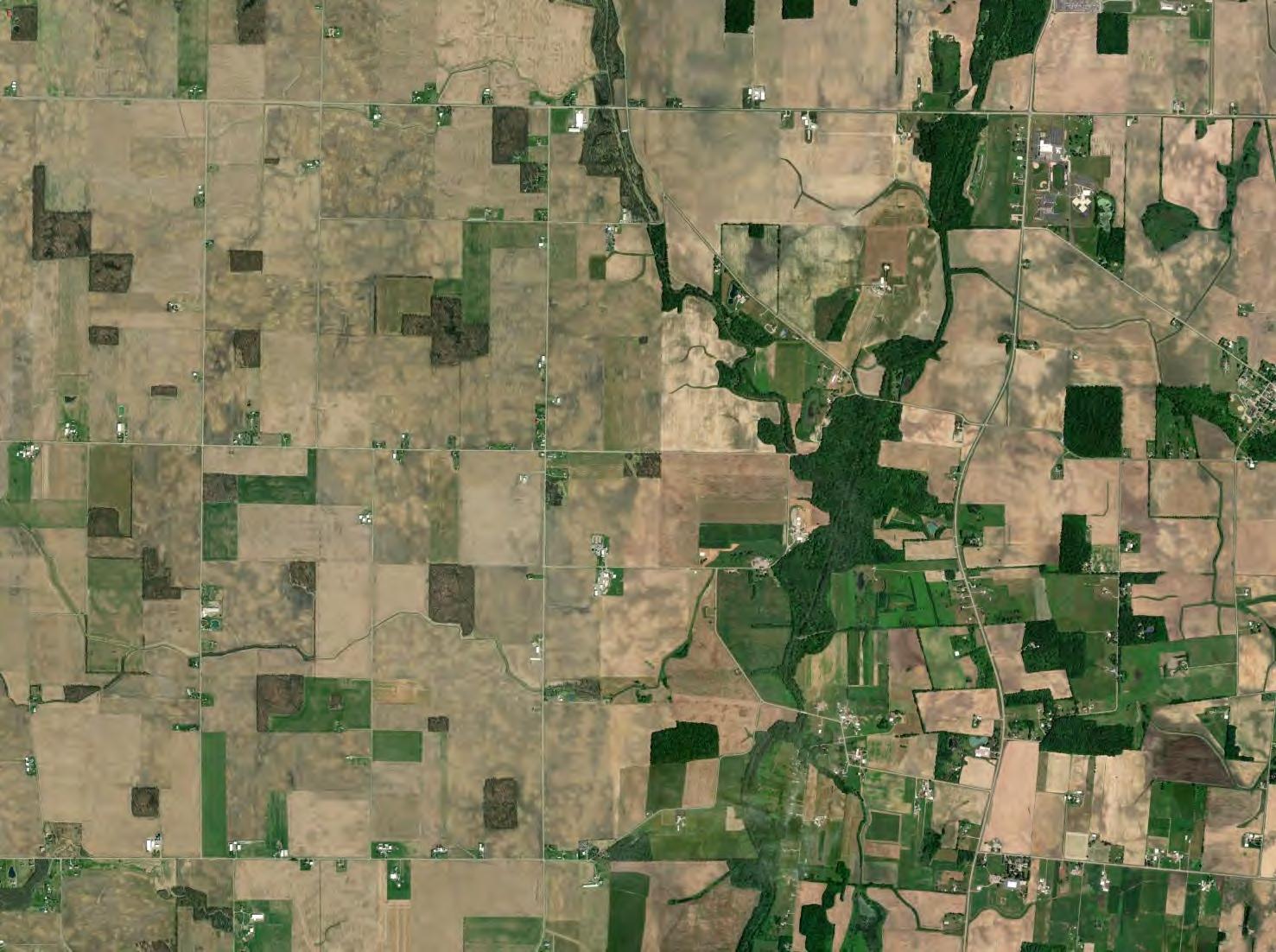
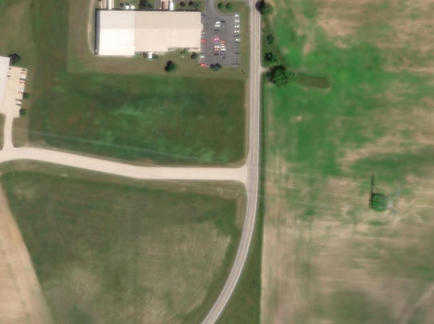
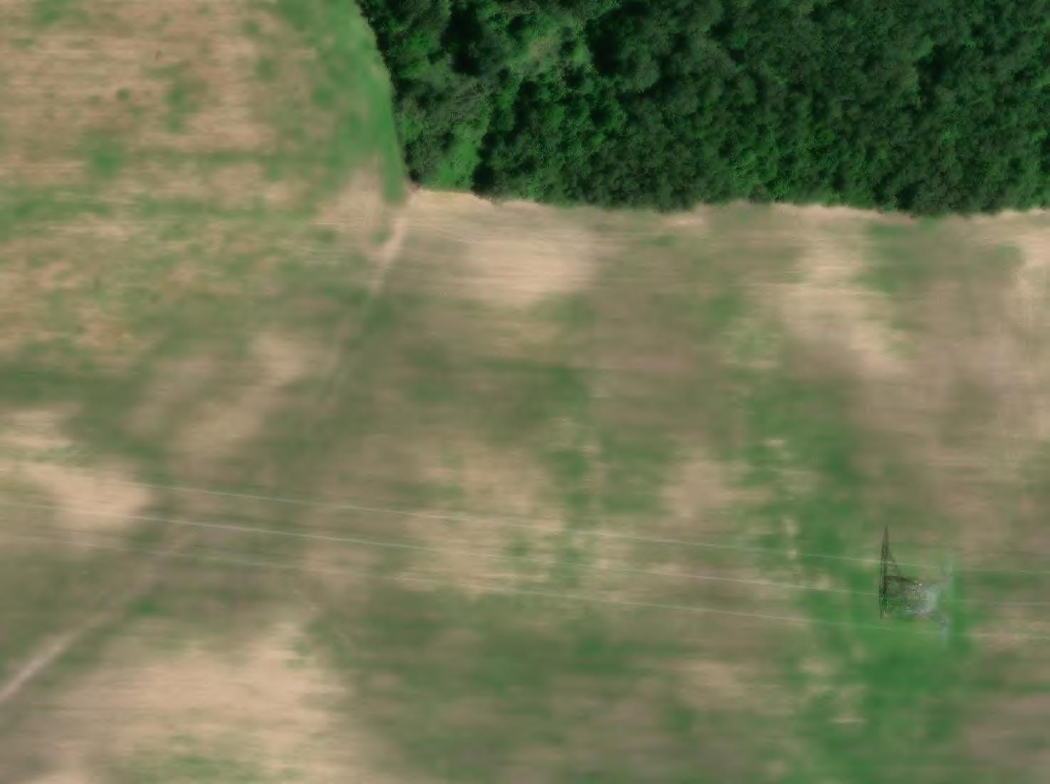
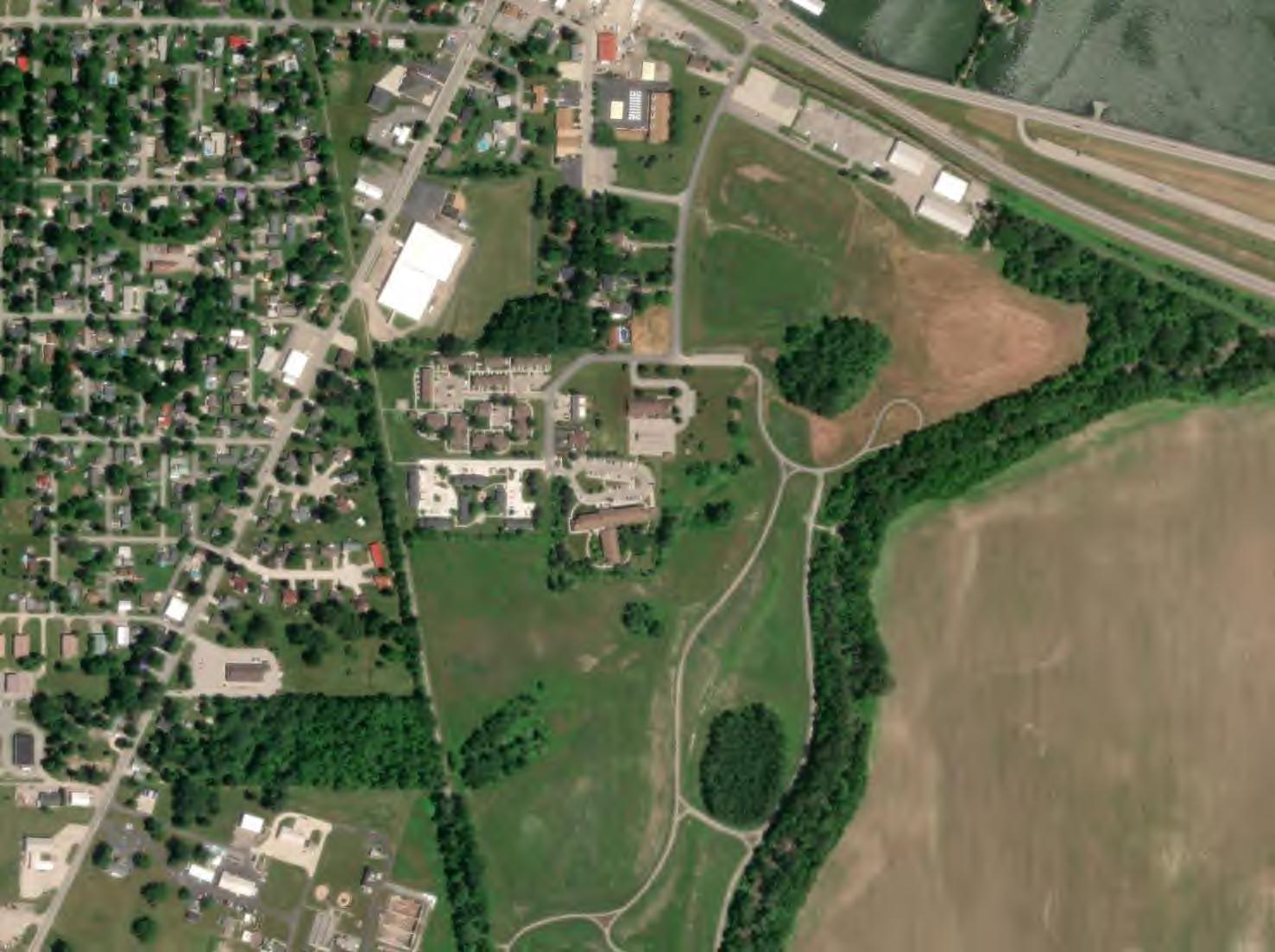
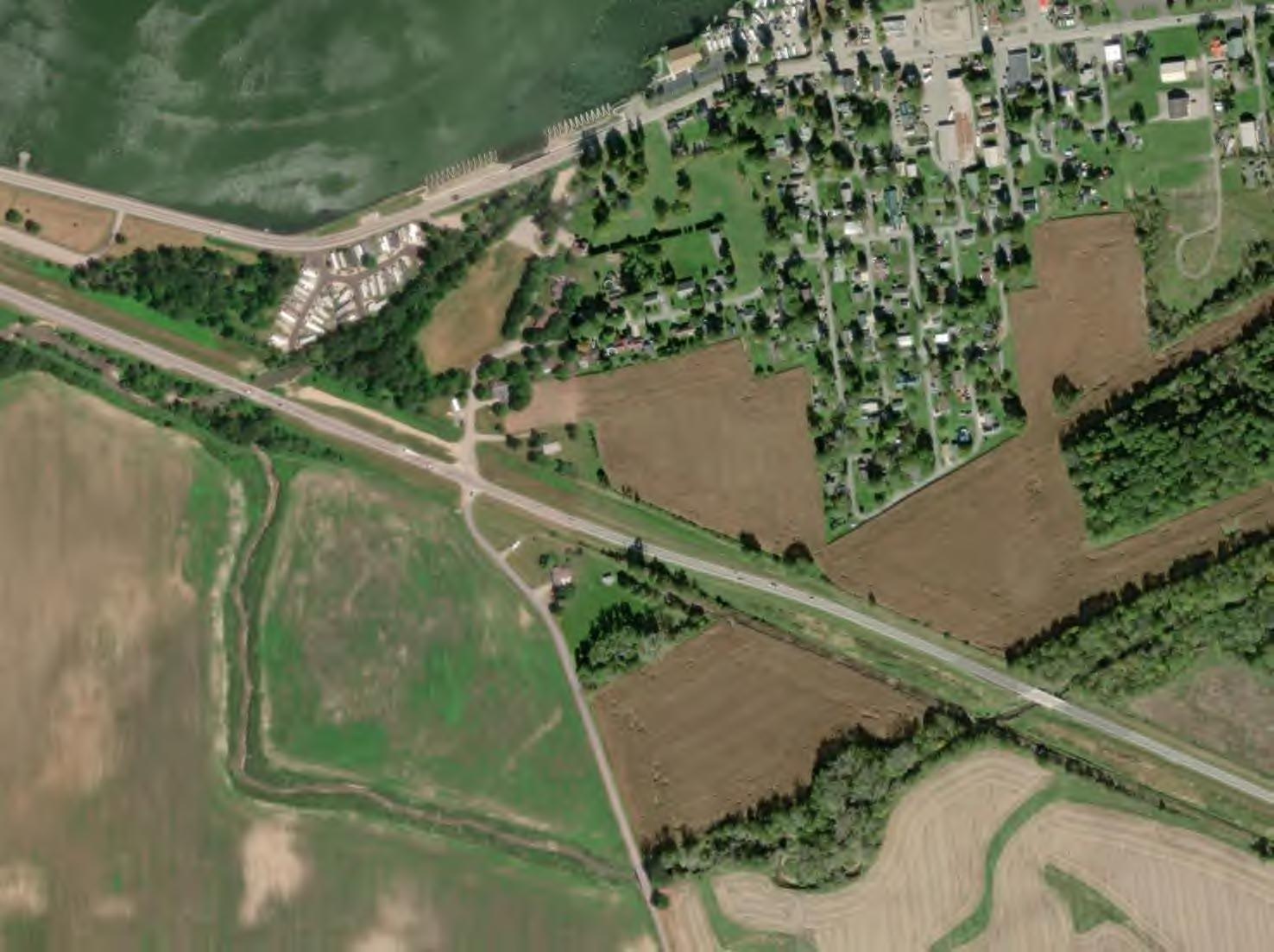
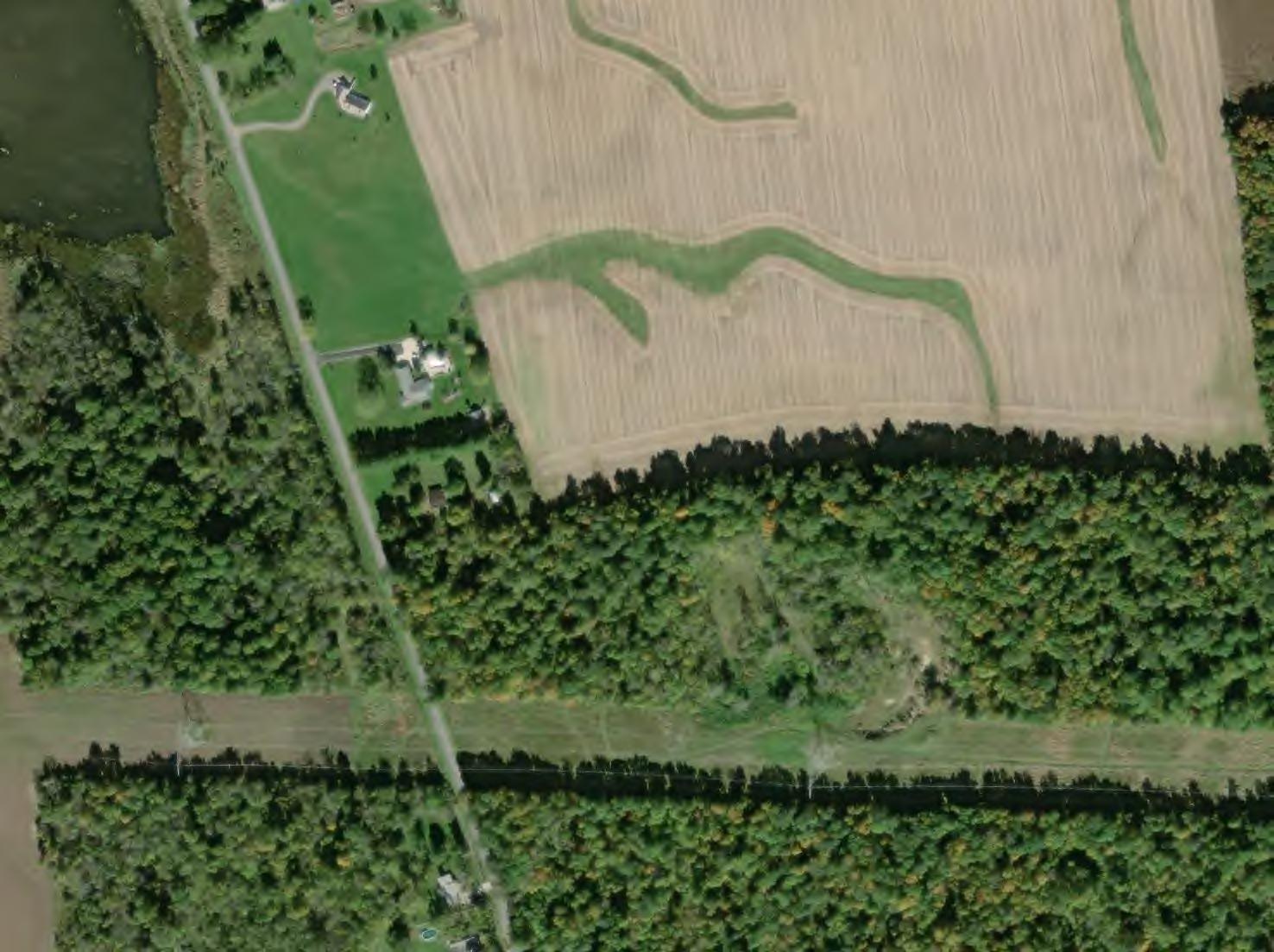
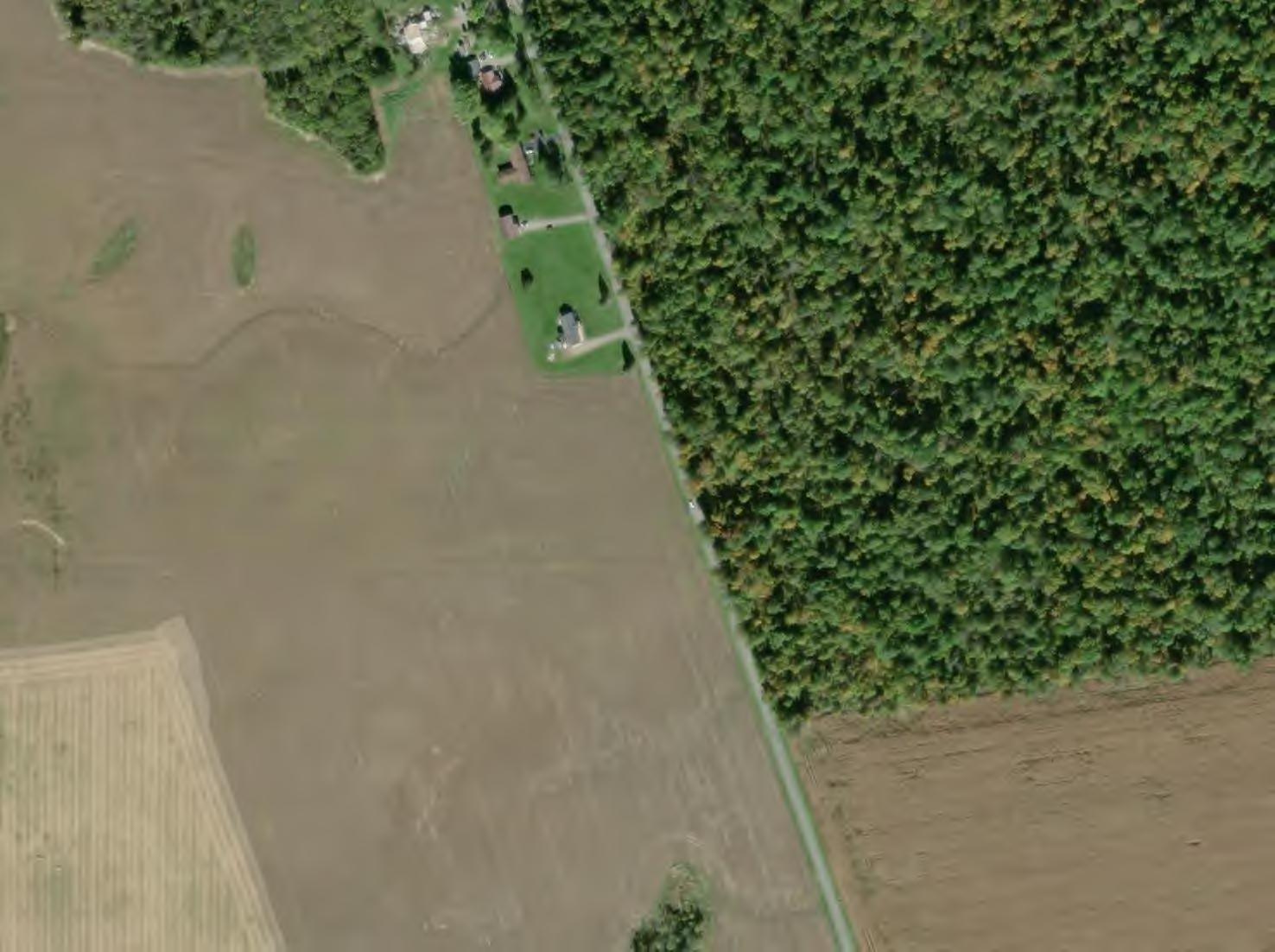
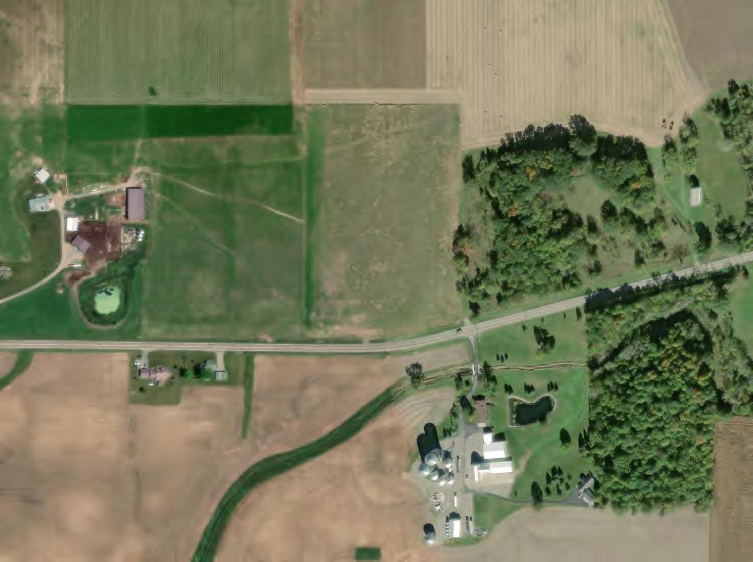
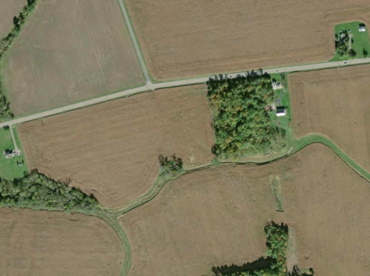
This Preliminary Drain Tile Assessment has been prepared for the Grange Solar Grazing Center. The Grange Solar Grazing Center is a combined utility-scale solar energy facility and sheep grazing operations being developed in Logan County, Ohio (hereafter referred to as the “Project” or the “Facility”). The Project will use ground-mounted solar panels to supply wholesale power to the existing electric grid while also providing pasture for livestock. All of the Project’s above-ground structures will sit within vegetated fields enclosed within agricultural-style fences, which also will confine the livestock and protect them from predators. The Project’s above-ground infrastructure will be located within approximately 2,600 acres of an area totaling approximately 4,100 acres (hereafter referred to as the “Study Area”). A map of the Study Area showing probable drain tile locations is included as Figure 1. Maps of larger scale of portions of the Study Area are included as Figures 2 through 58.
The objective of this assessment is to identify, to the extent practicable, the location (or probable location) of existing agricultural drain tile so that it can be avoided or modified when designing and constructing a ground-mounted solar photovoltaic array.
Agricultural drain tile is a piped underground utility used to remove excess subsurface water from agricultural fields in order to promote optimum moisture conditions in the soil. Drain tile is typically a perforated plastic, concrete, or clay pipe designed to allow subsurface water to infiltrate the pipe and drain via gravity to natural or manmade outlet points (i.e., ditch, swale, pond, etc.). Drain tiles are often constructed as a network made up of smaller lateral pipes combining into larger drain tile mains. Drain tile networks can cross property lines and serve multiple landowners. Of particular importance and focus of this effort is the identification of drain tile mains located within the project parcels as well as drain tile systems that may be connected on non-participating parcels.
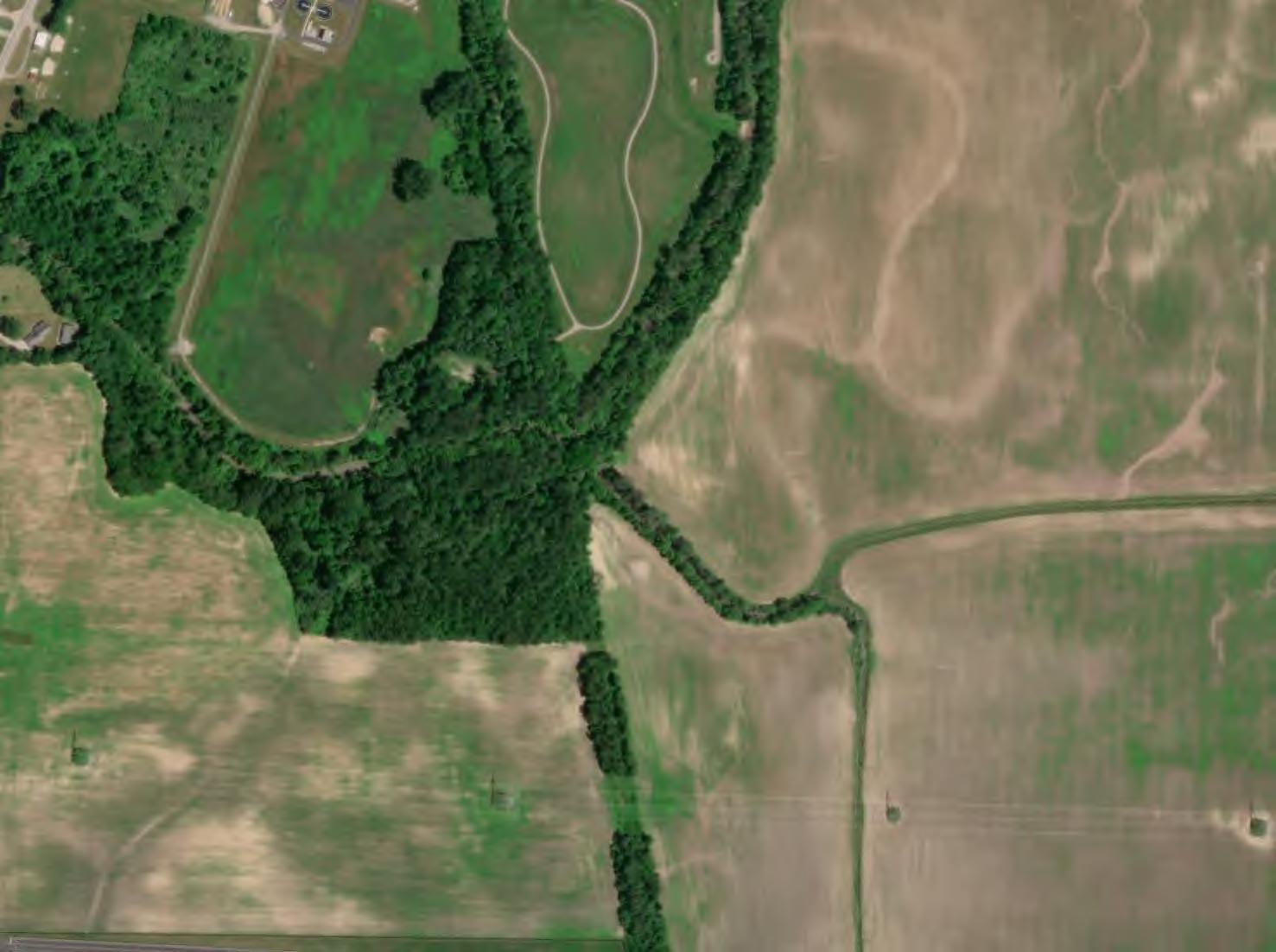
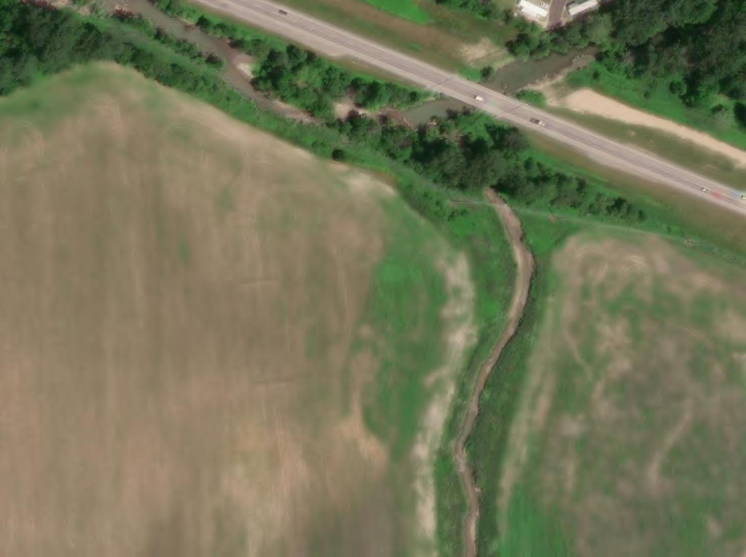
Methods of identifying the location and routing of agricultural drain tile when the location is not known include mapping, visual indicators, and physical exploration. This assessment was limited to mapping and visual indicator techniques. Verdantas also completed a visual reconnaissance of any drain tile outfalls within the delineated streams in the Study Area.
Additional methods to identify existing drain tile, such as physical exploration could be used for final design prior to and during construction if necessary and are discussed in Section 2.3, below.

If available, landowners provided mapping of the drain tile as provided by the installation contractor. If no such mapping was available, each participating landowner was provided with a map of their property so they could sketch, to the best of their knowledge, the location and type of any drain tiles. Each map contained an aerial image, Study Area outline, county drain tile lines, and topographic contours. Using these maps as a guide, landowners were asked to provide as much information regarding the location of existing drain tile as possible. They were asked to differentiate between drain tile mains and laterals (or pattern tile) wherever possible. At this time, most landowners have provided knowledge of the drain tile systems on their properties. Landowner communication and mapping is ongoing, and the dataset will be updated if additional data becomes available during final design and prior to construction.
Verdantas also coordinated with the Logan County Engineer’s Office and Logan County Soil and Water Conservation District. The Logan County Engineer’s Office maintains information for drain tile systems in Logan County, which was provided to Verdantas in a zipped shapefile that was then incorporated into the maps. The Logan County Soil and Water Conservation District did not respond with any additional information.
To identify drain tile locations, aerial imagery was acquired from multiple sources including the following:
• The Ohio Geographically Referenced Imagery Program (2020)
• LightBox Historical Aerials (1938 – 2017)
• Esri (2016 – 2020)
• Google Earth (2004 – 2022)
The imagery noted above was analyzed for the following indicators:
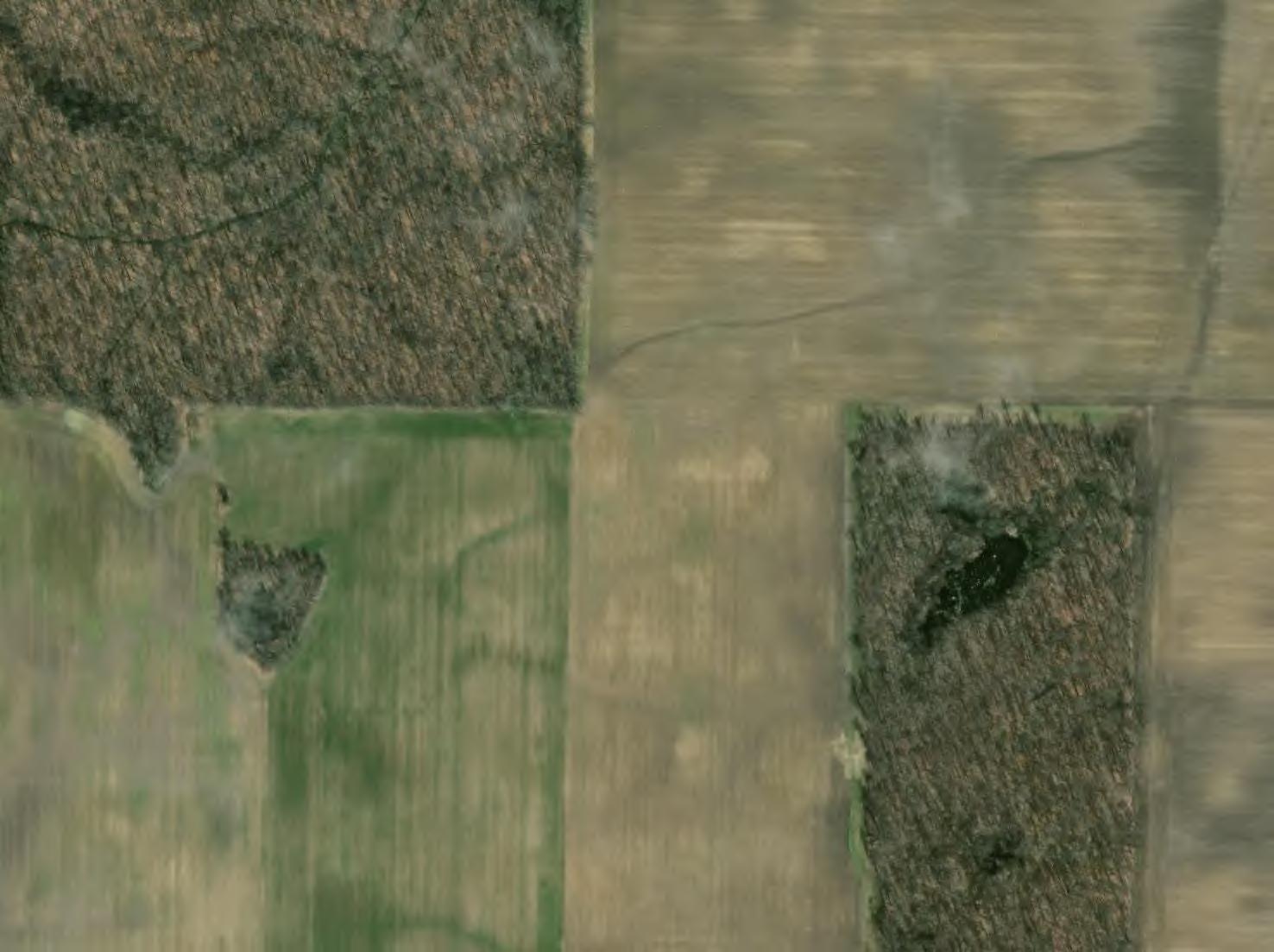
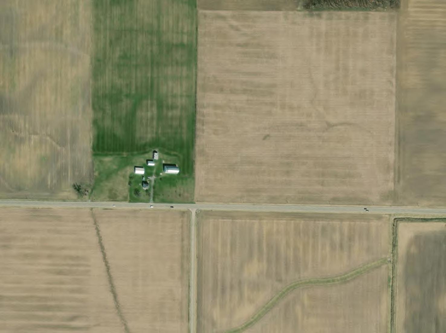
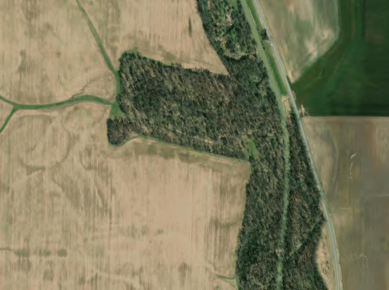
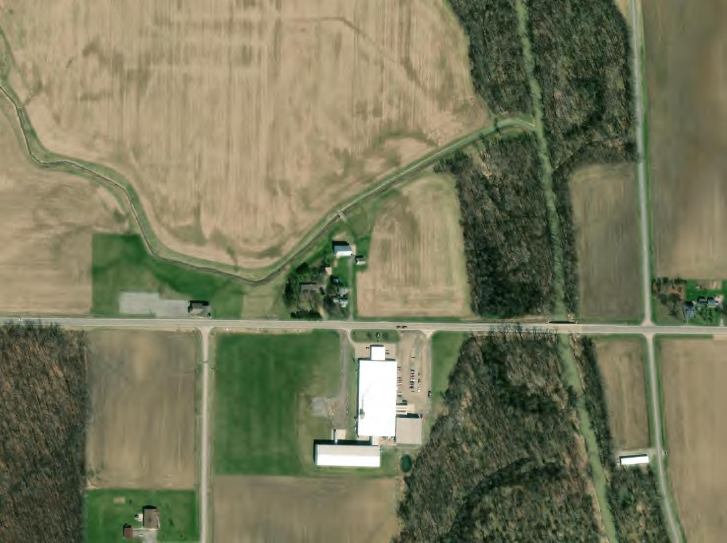
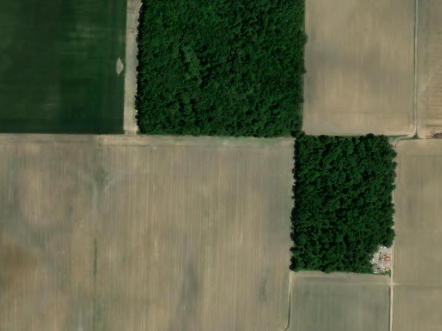
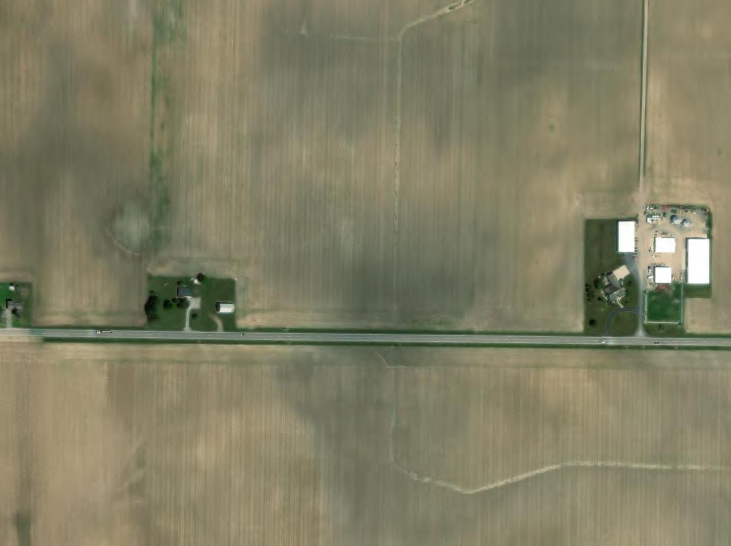
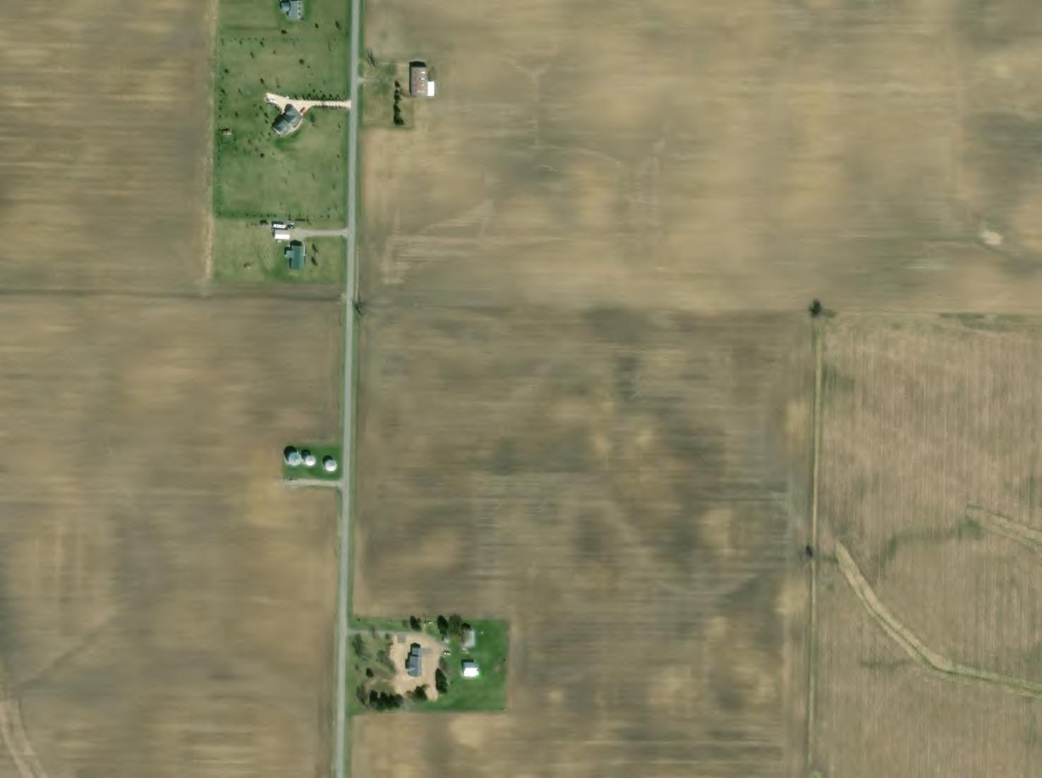
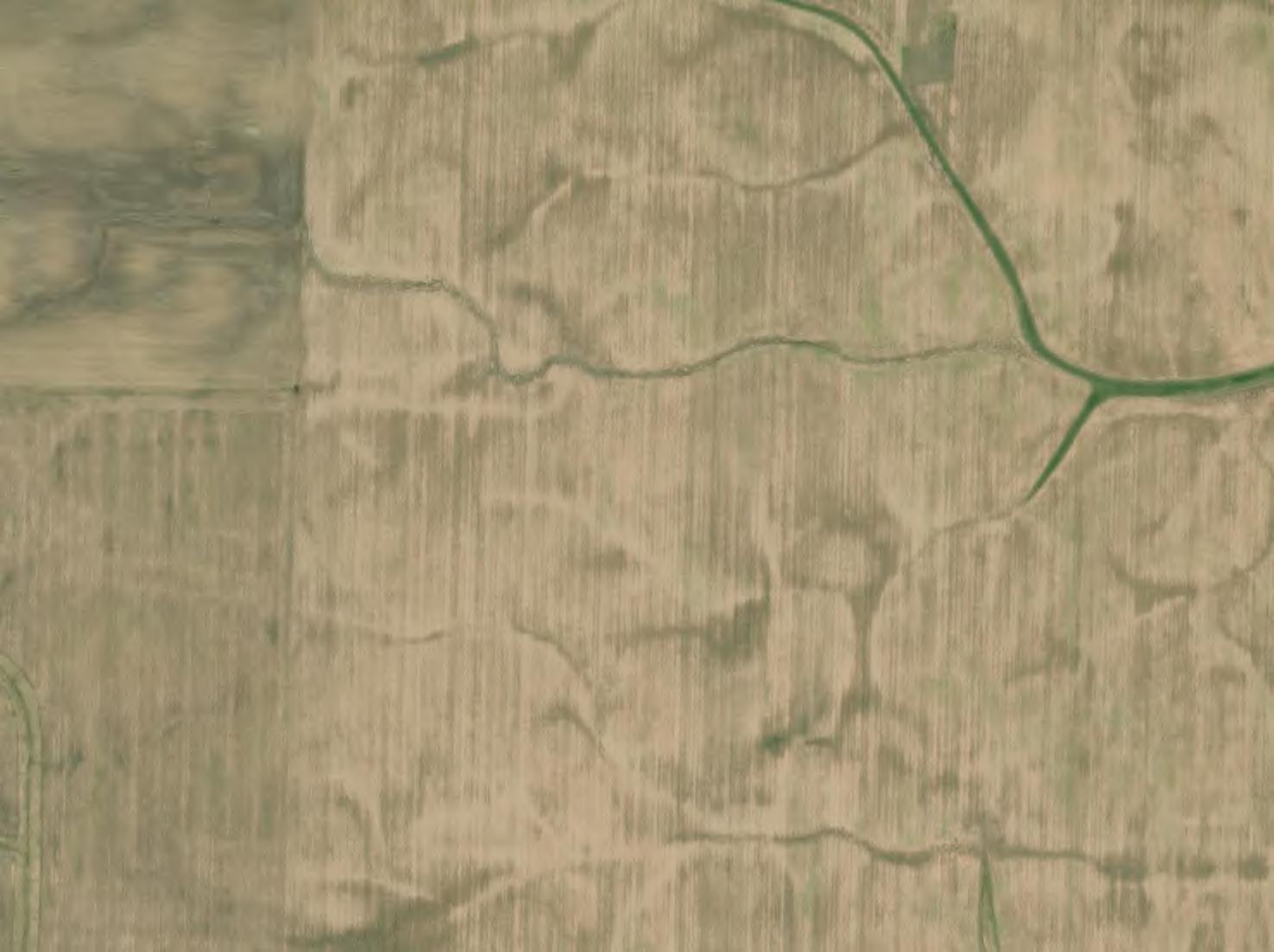
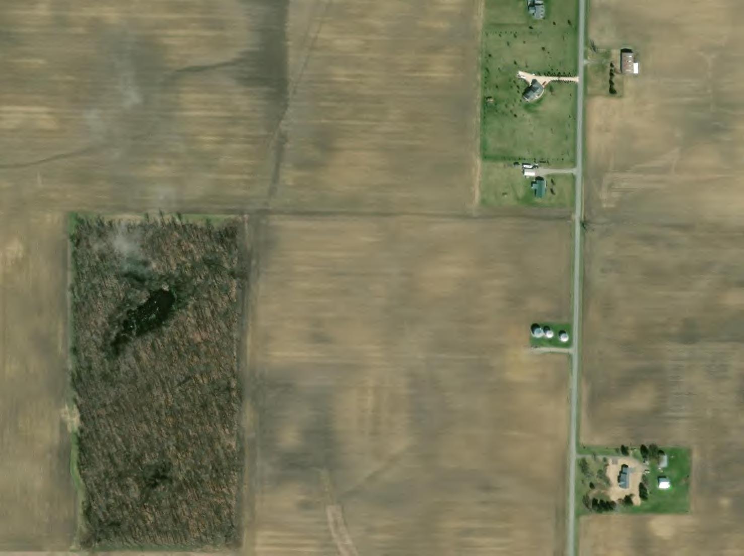
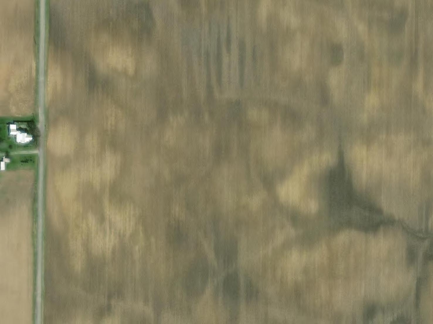
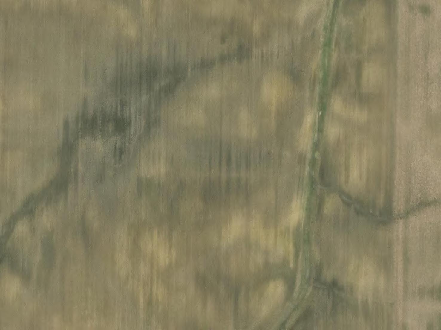
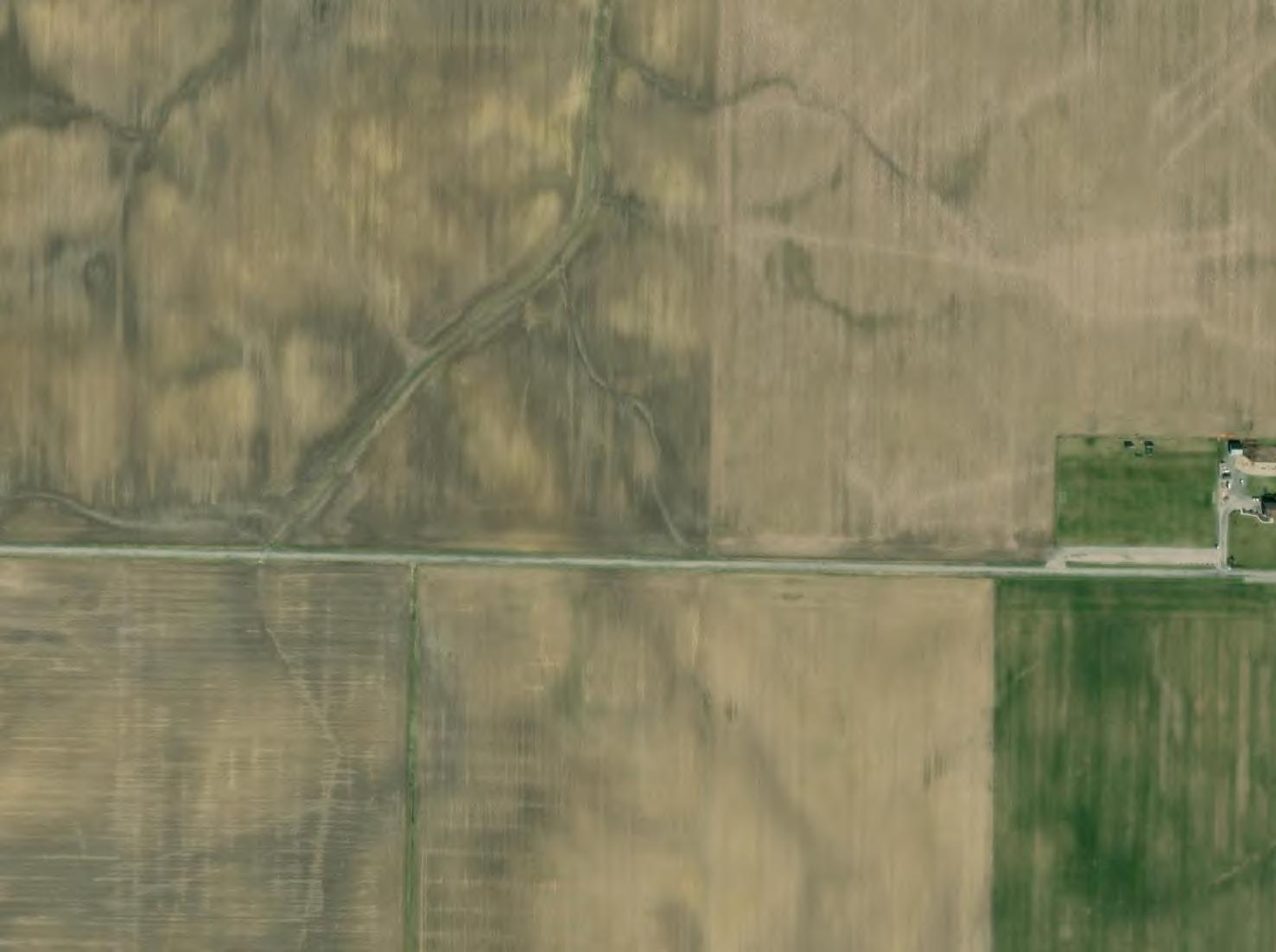
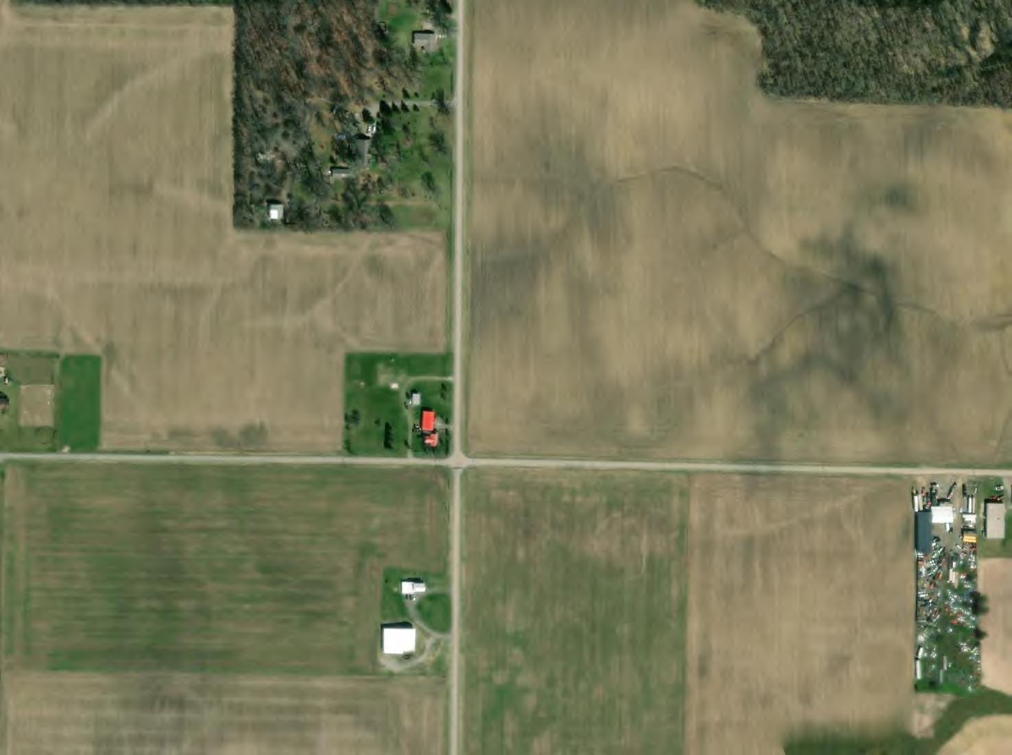
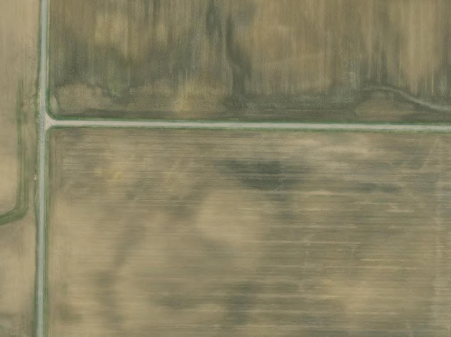
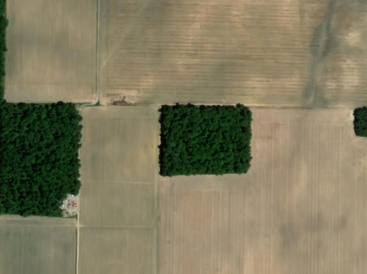
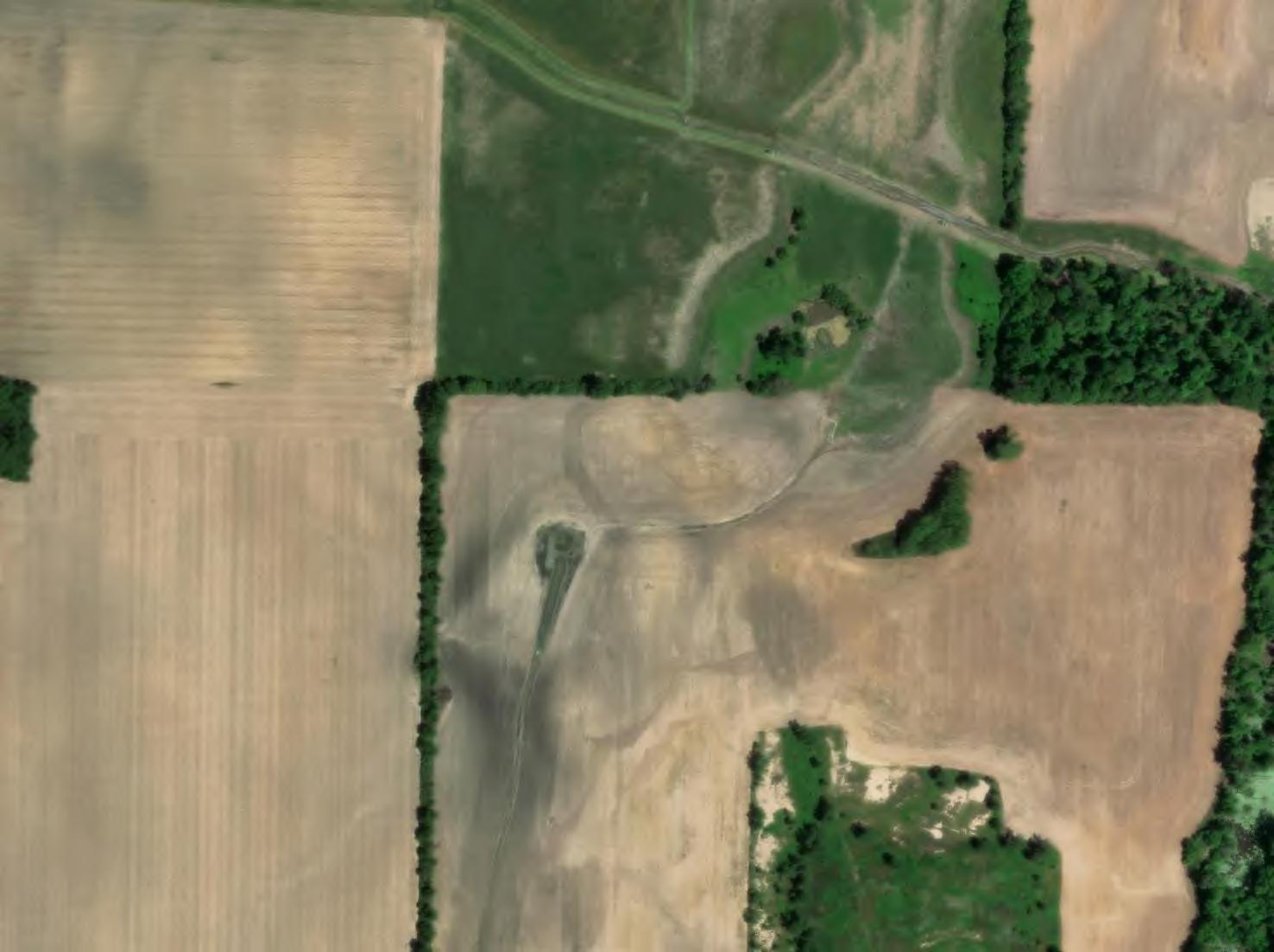
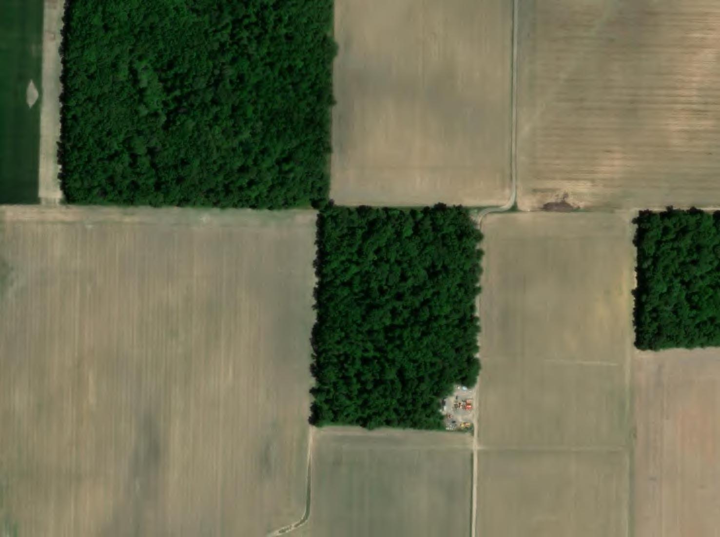
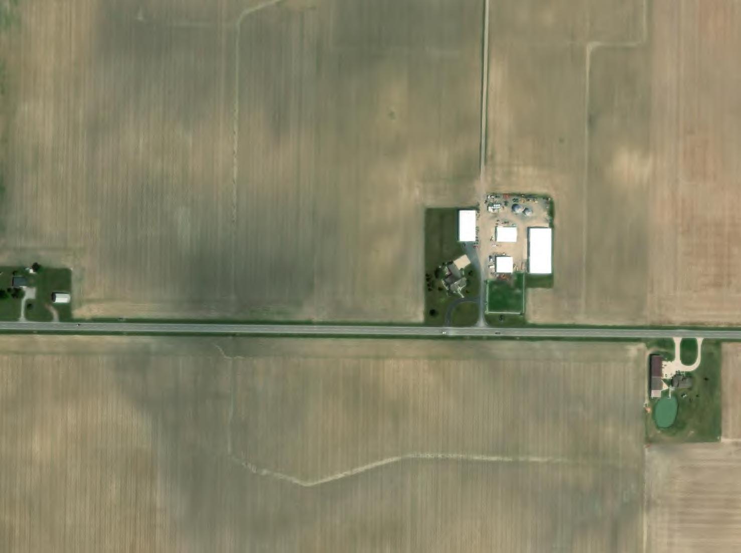
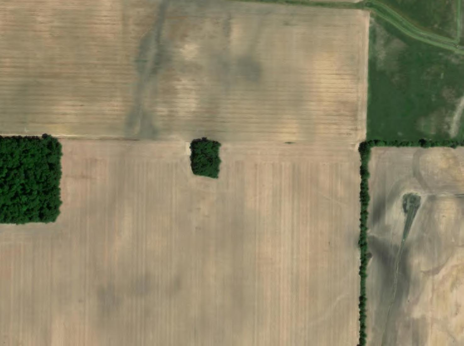
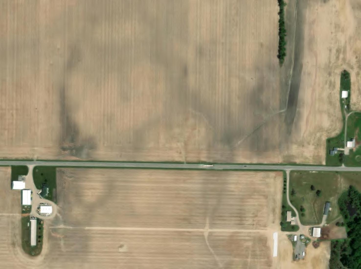
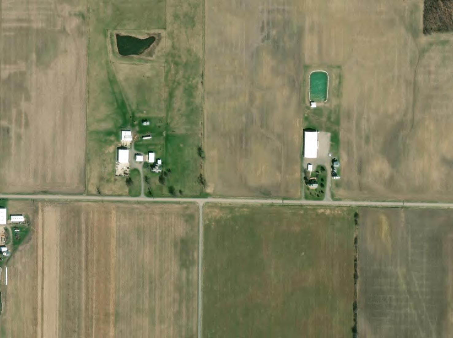
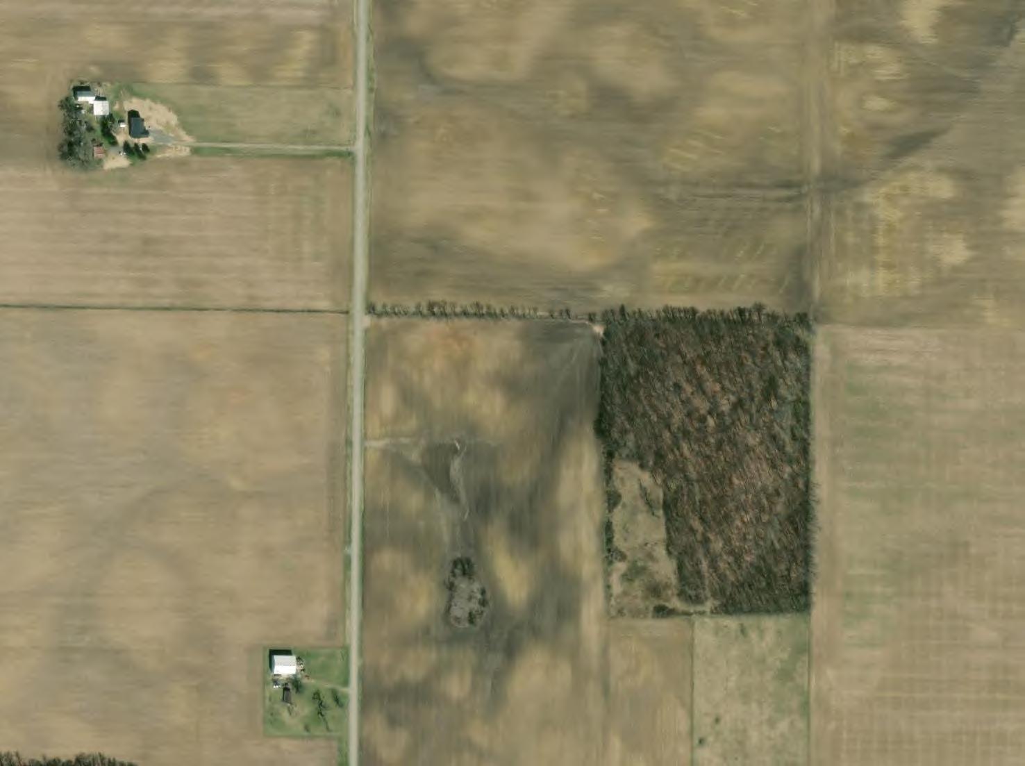
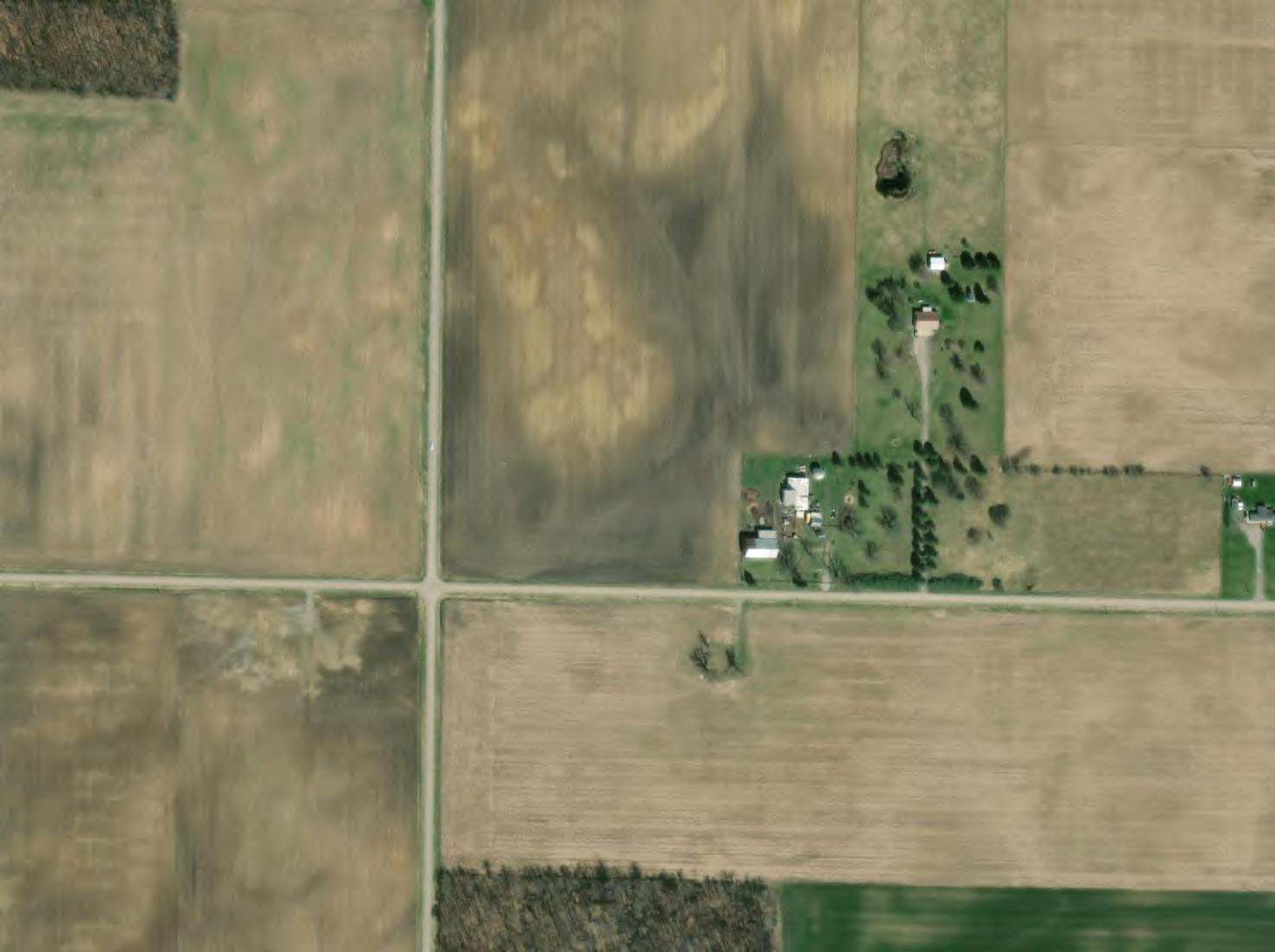
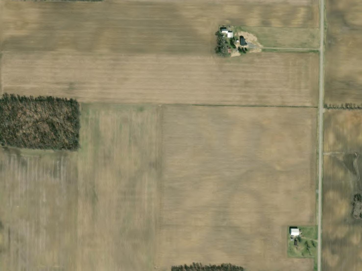
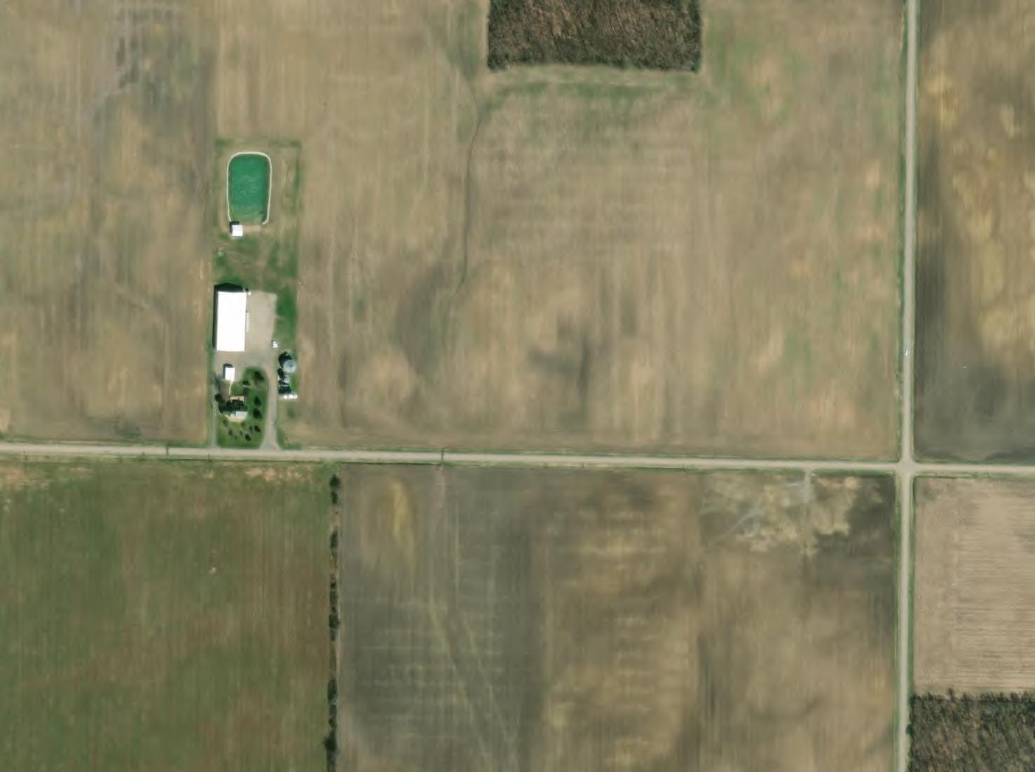
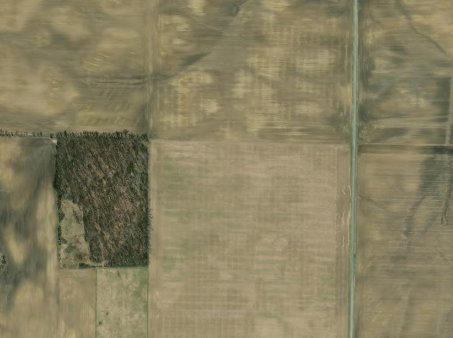
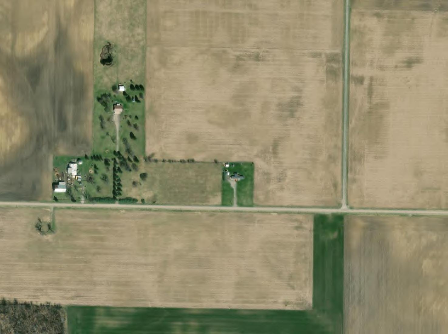
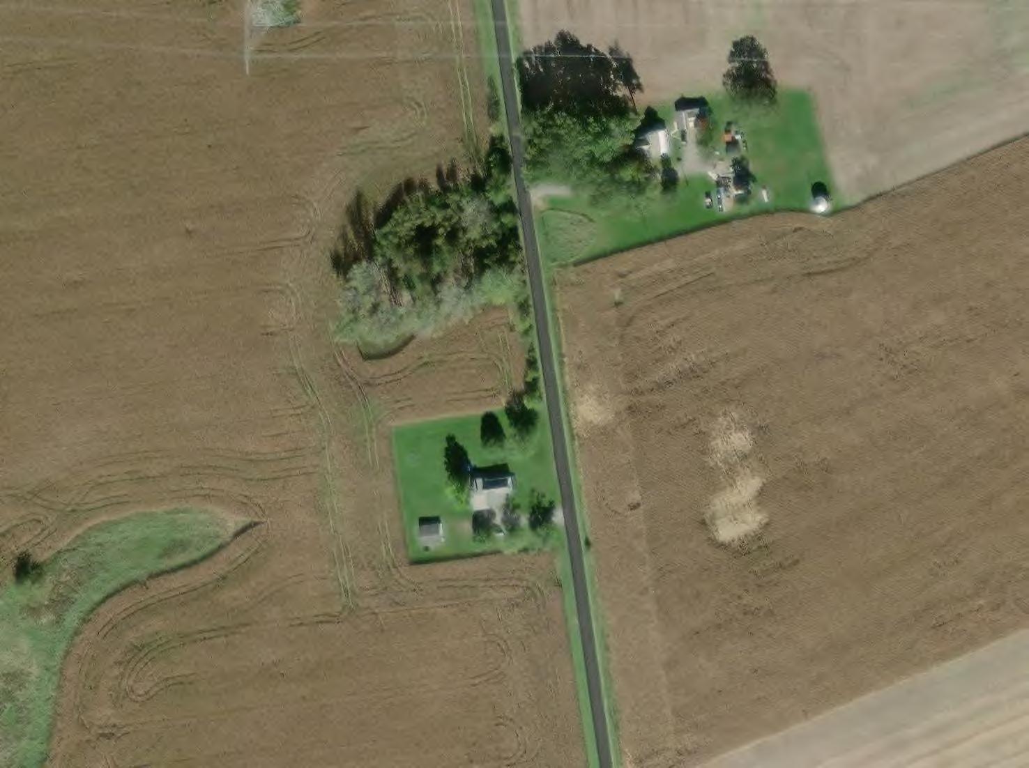
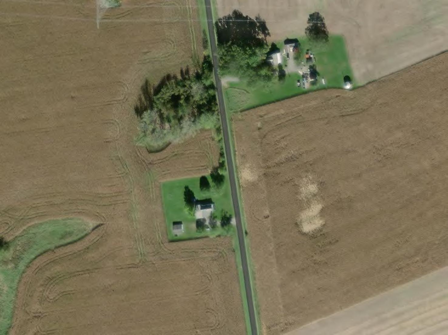
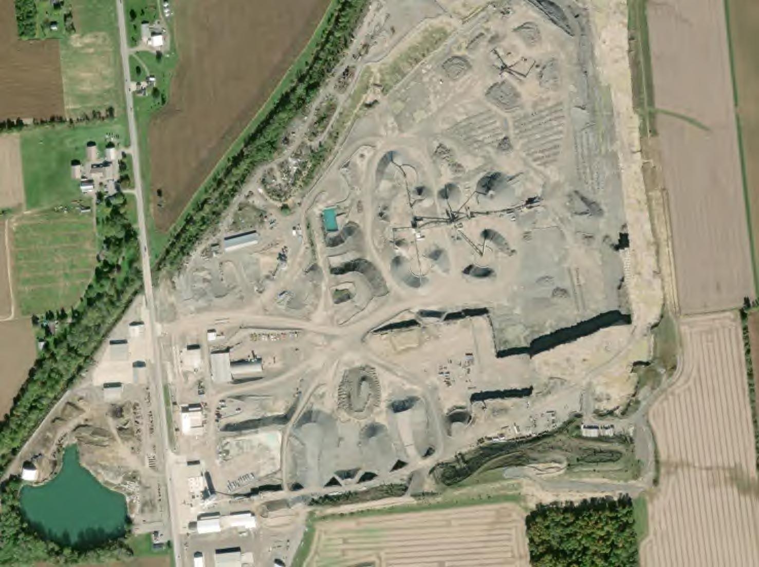
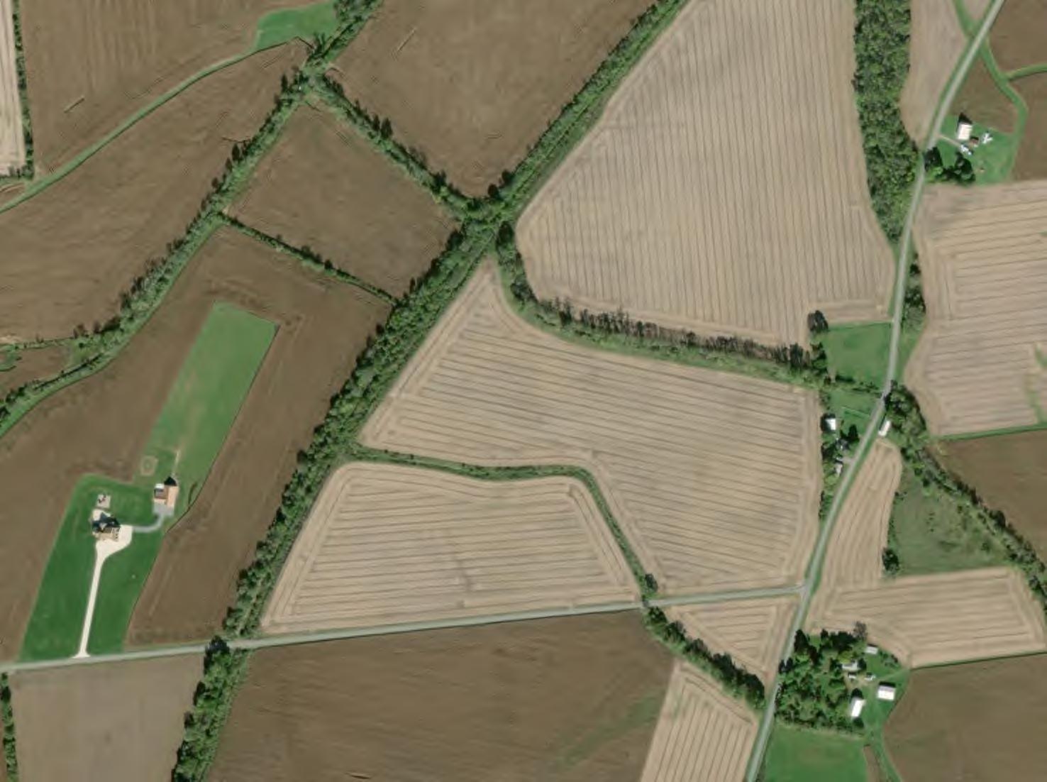
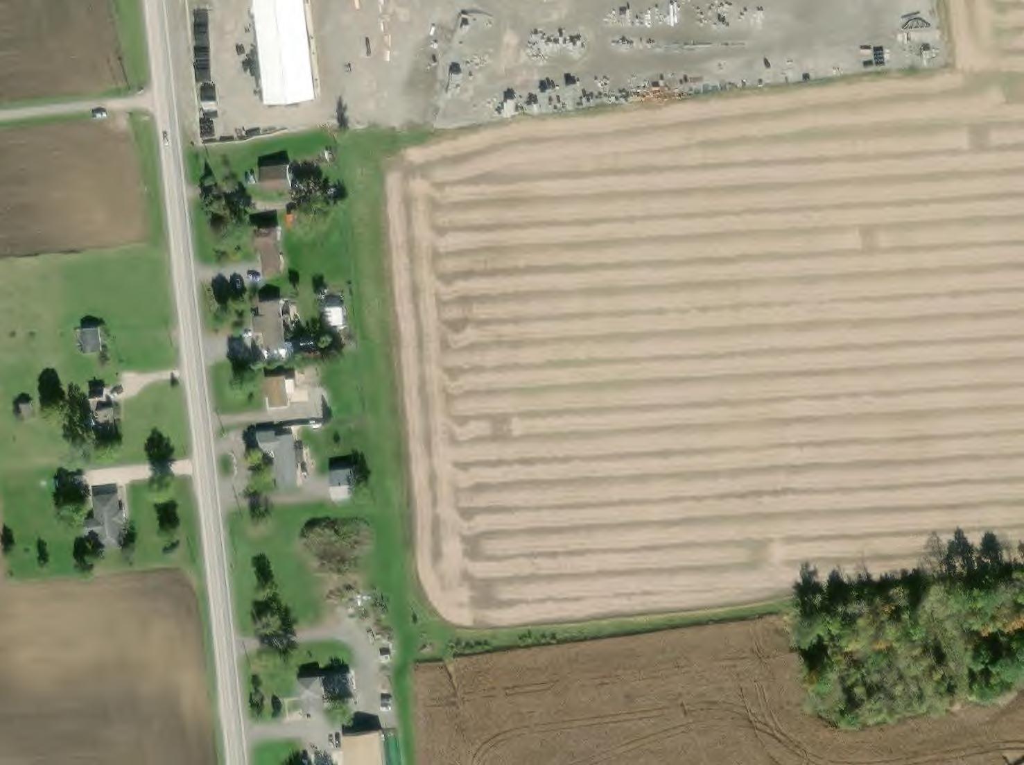
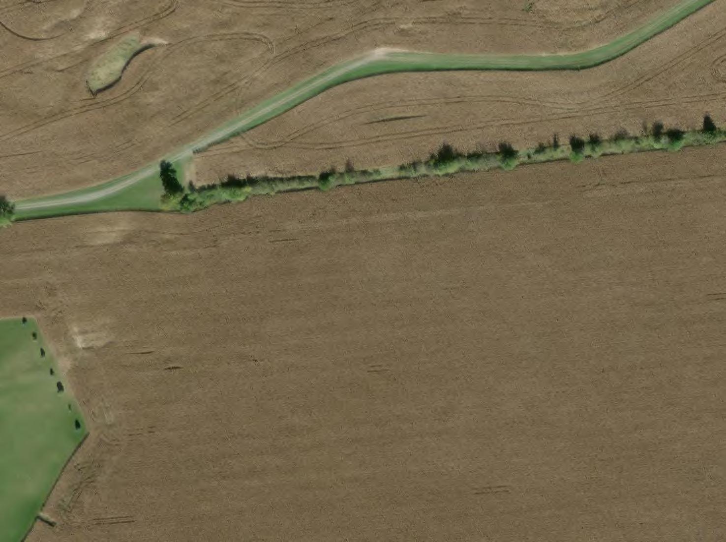
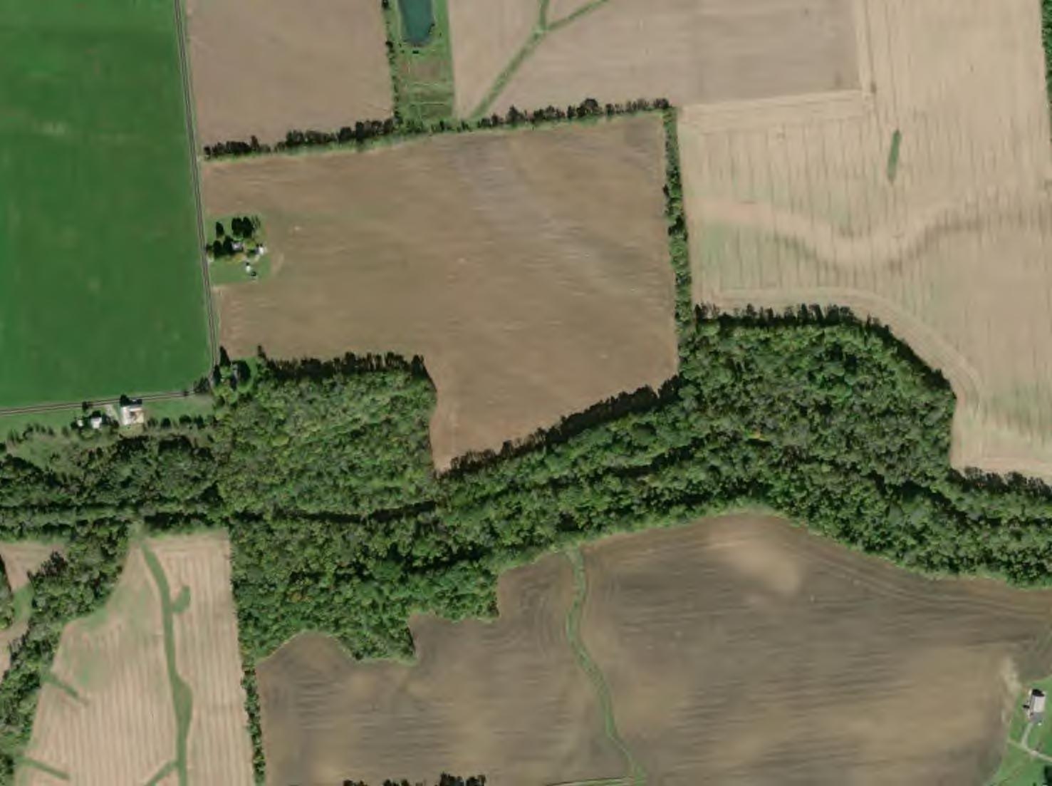
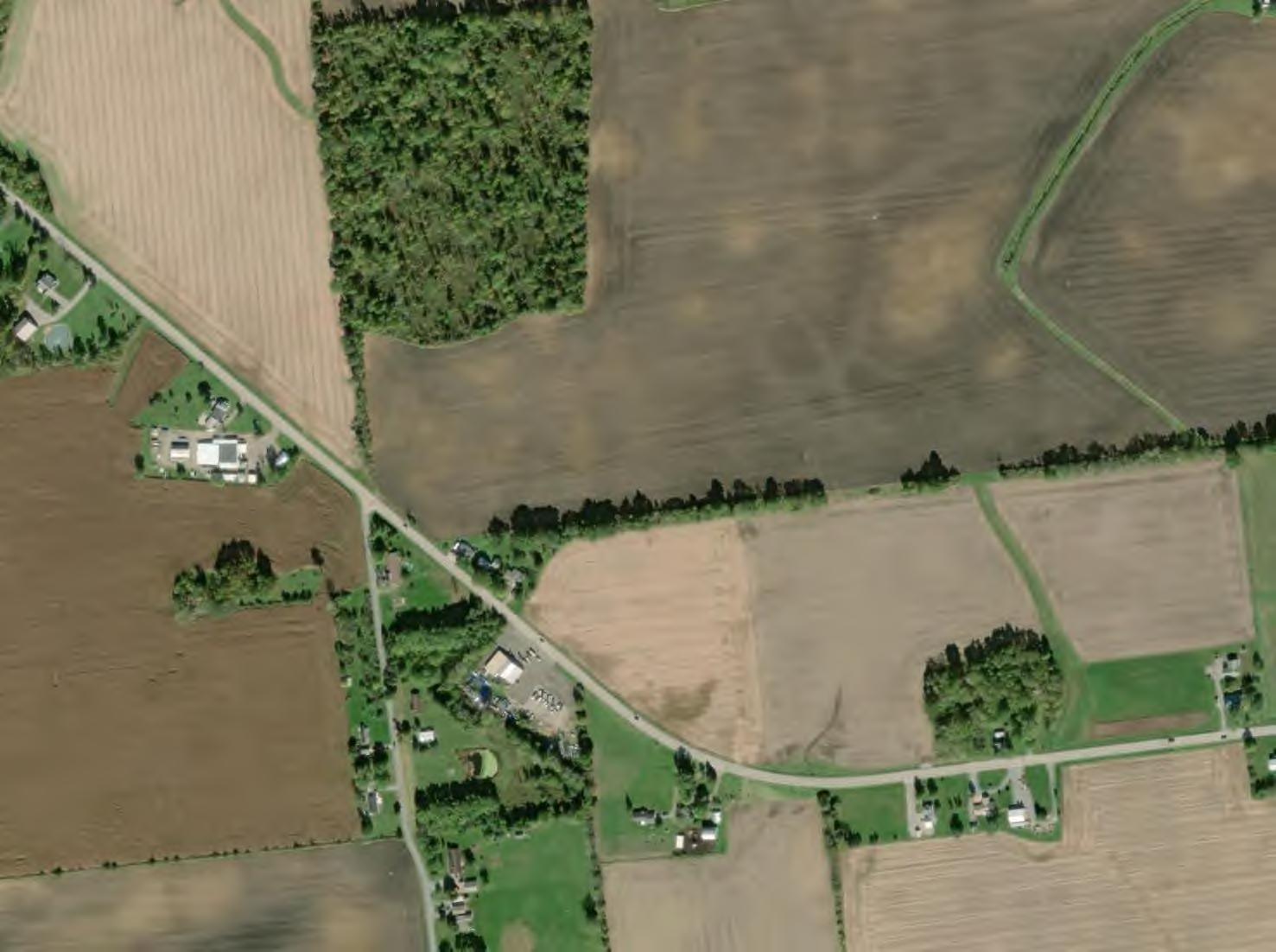
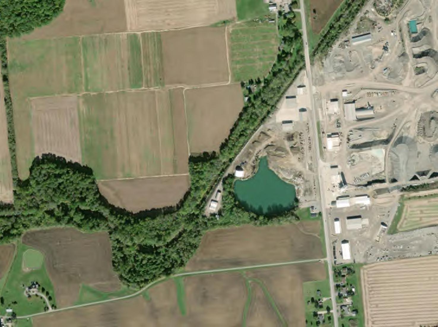
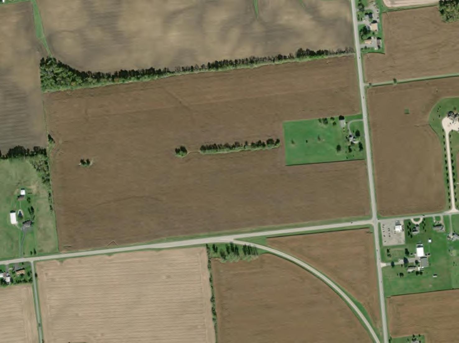
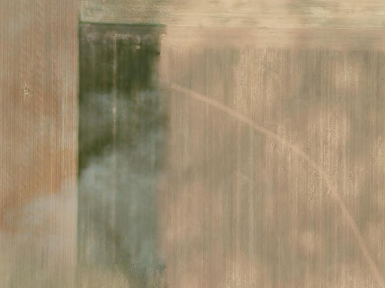
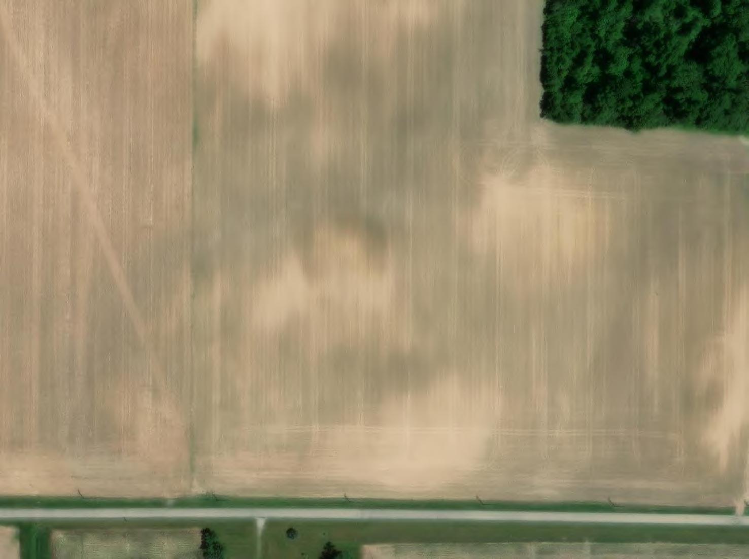
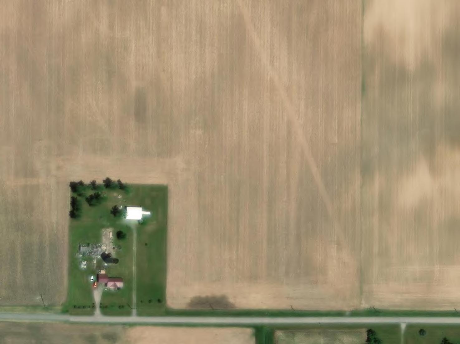
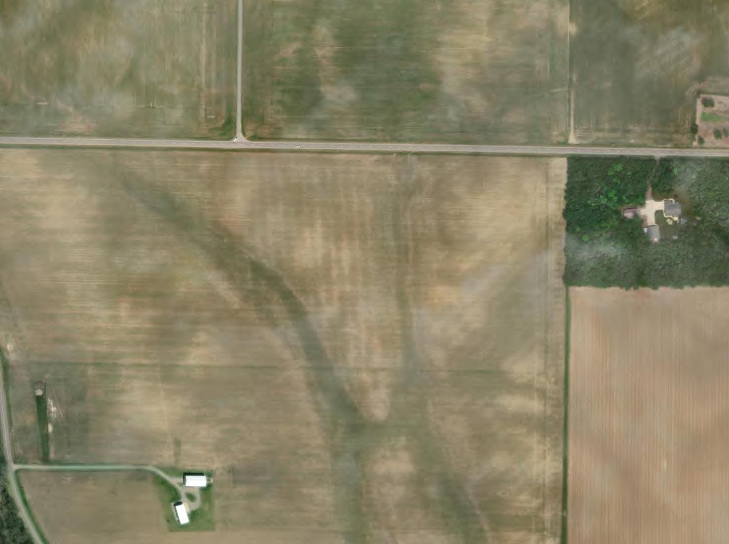
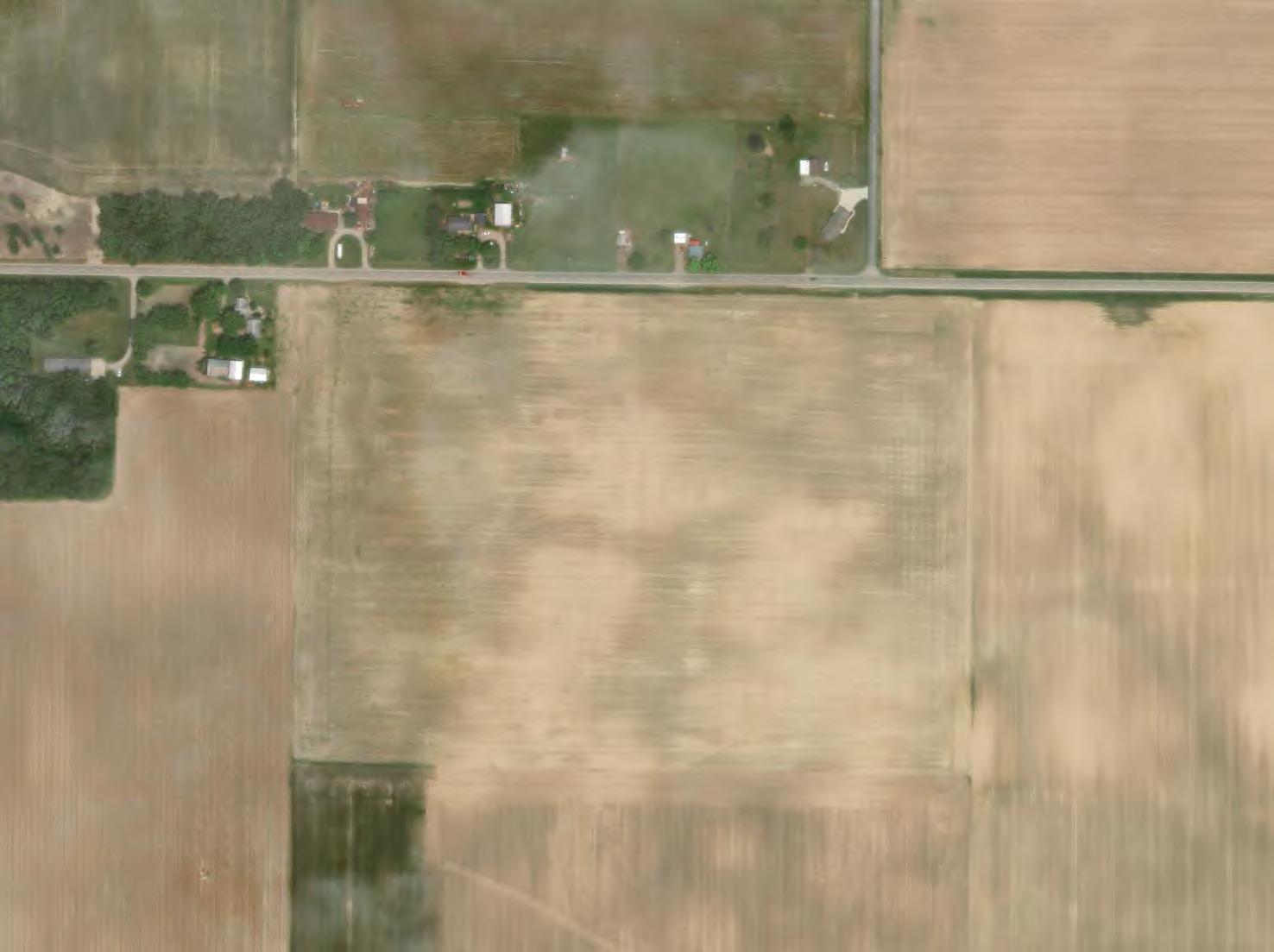
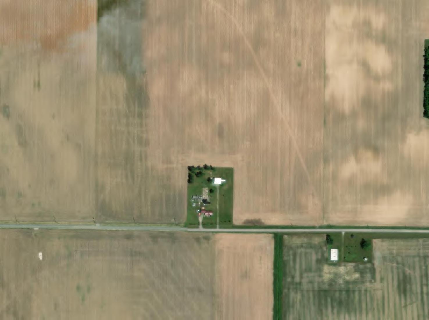
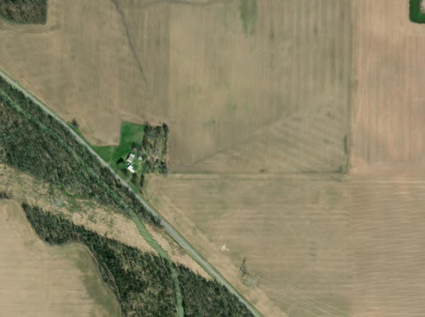
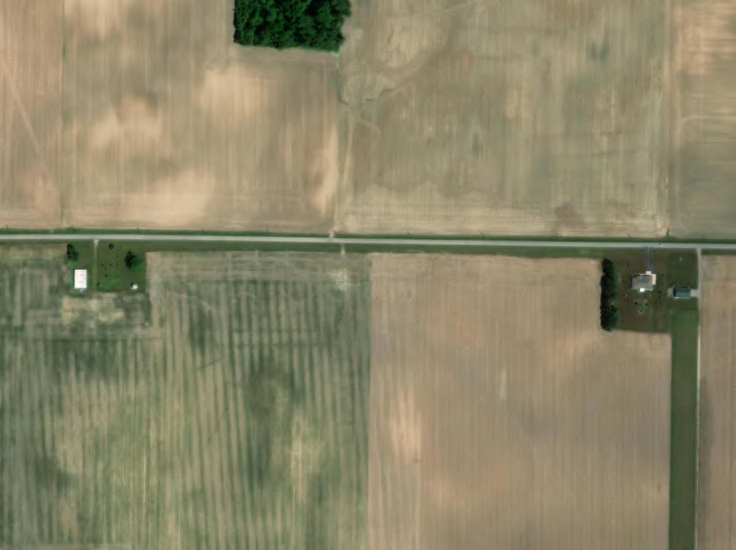
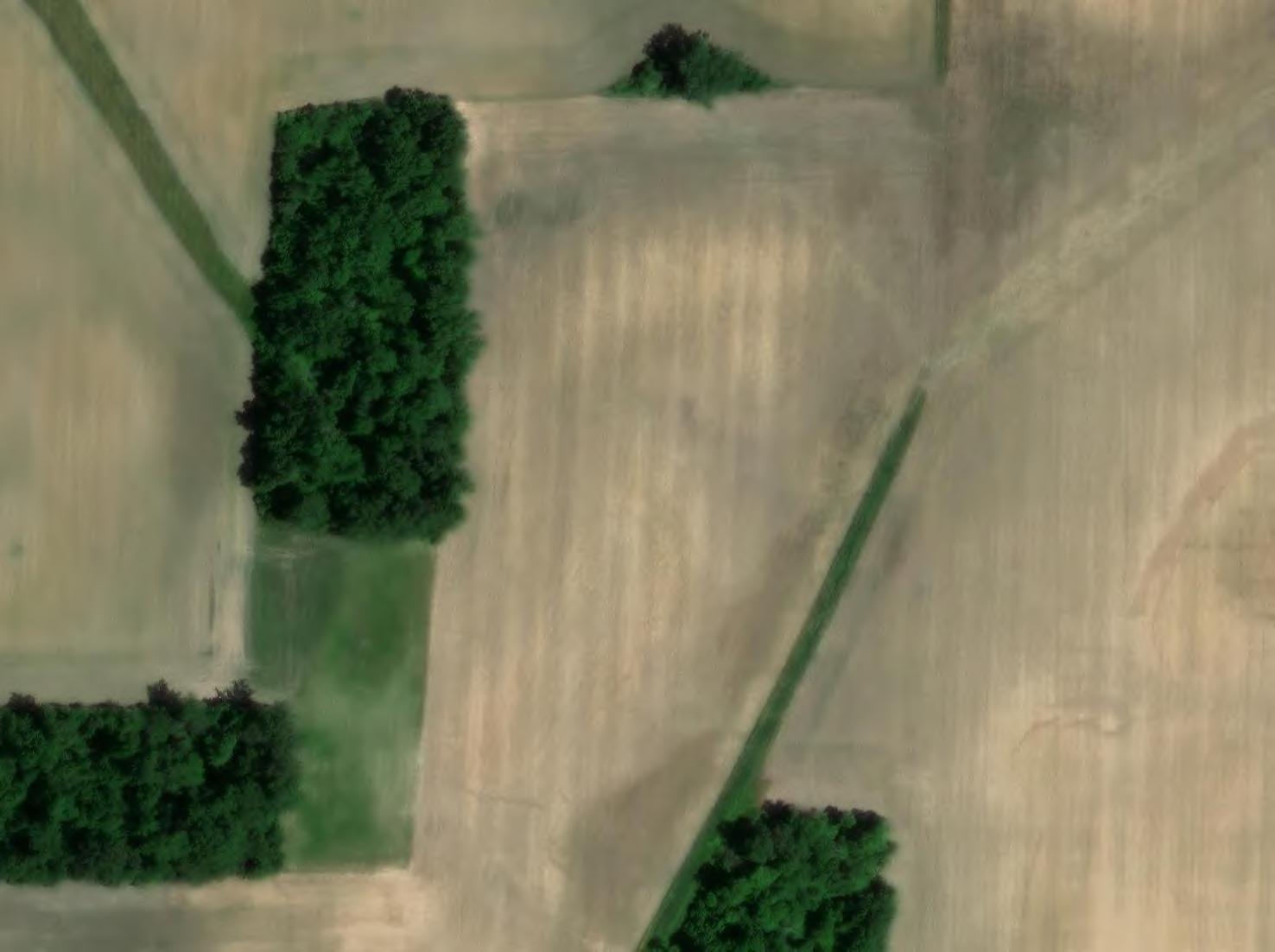
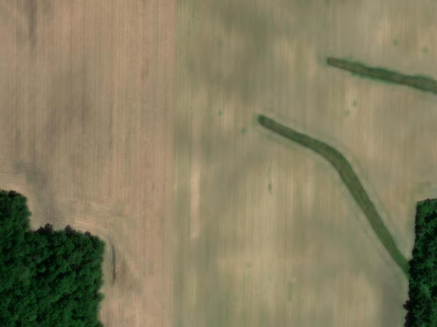
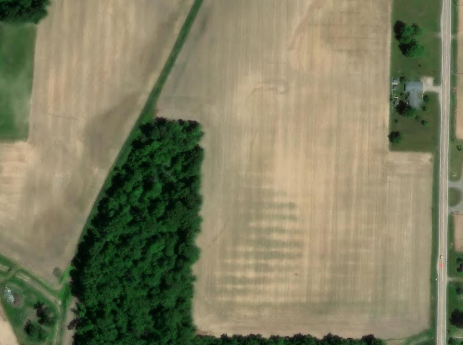
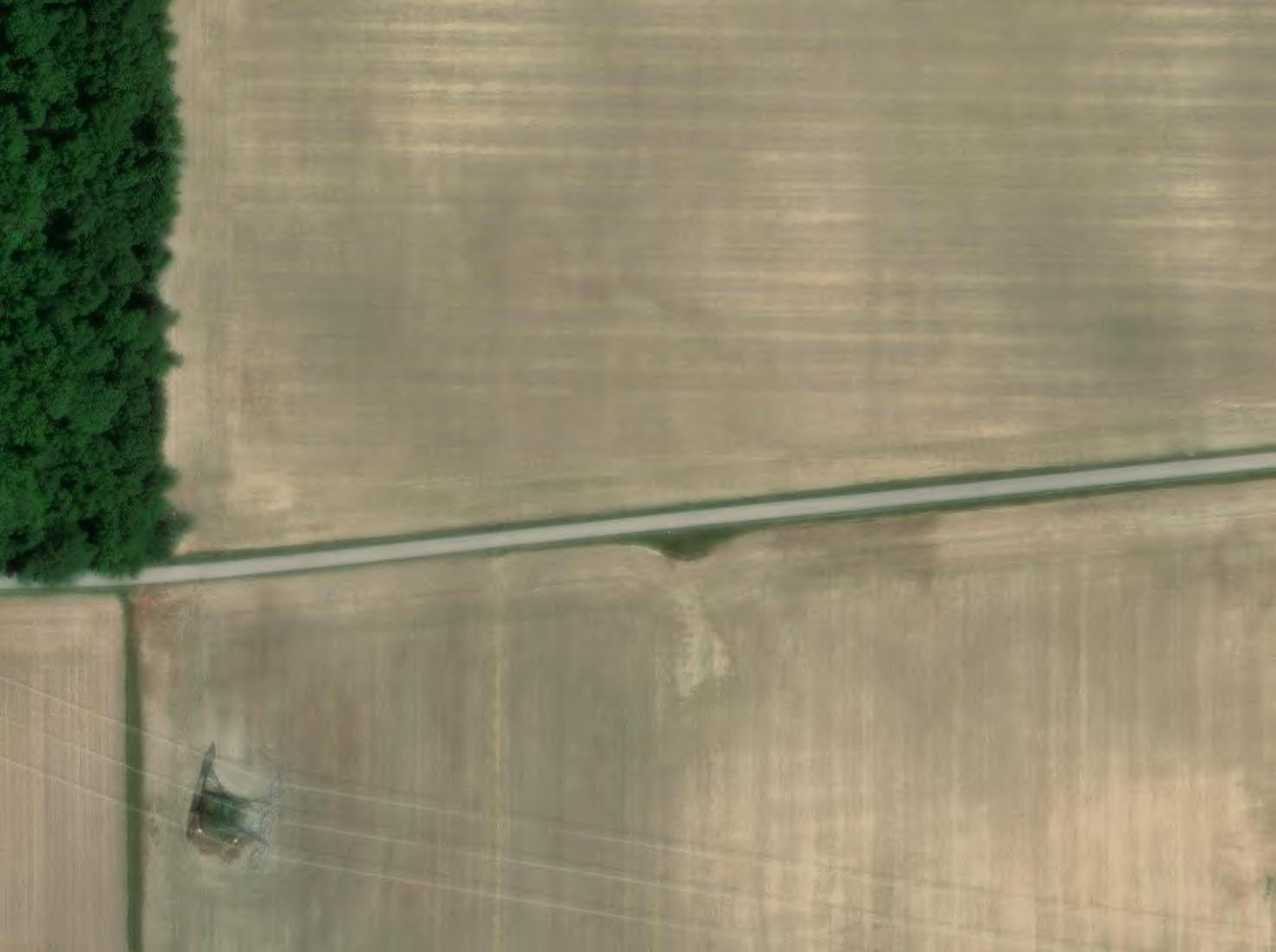
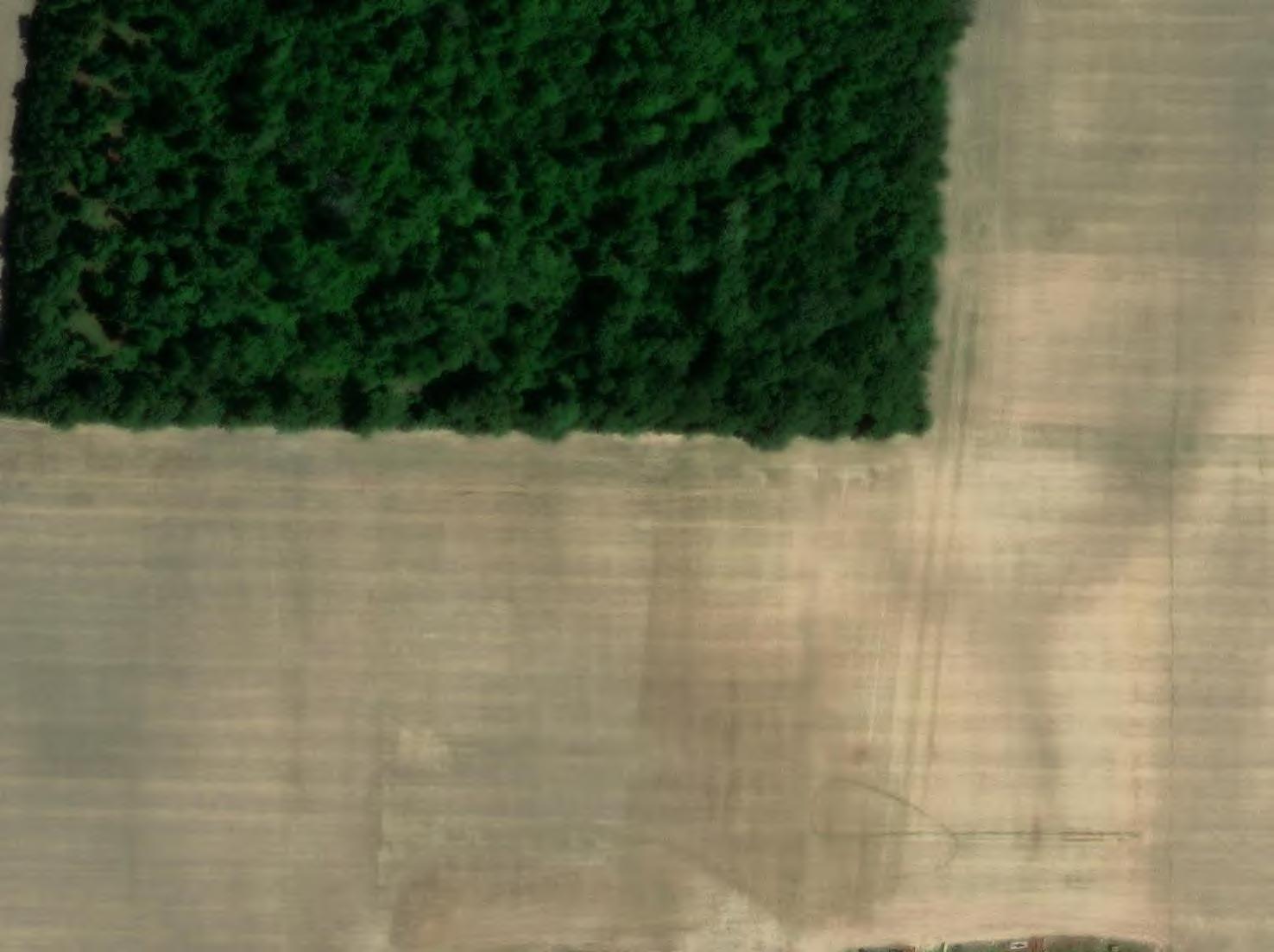
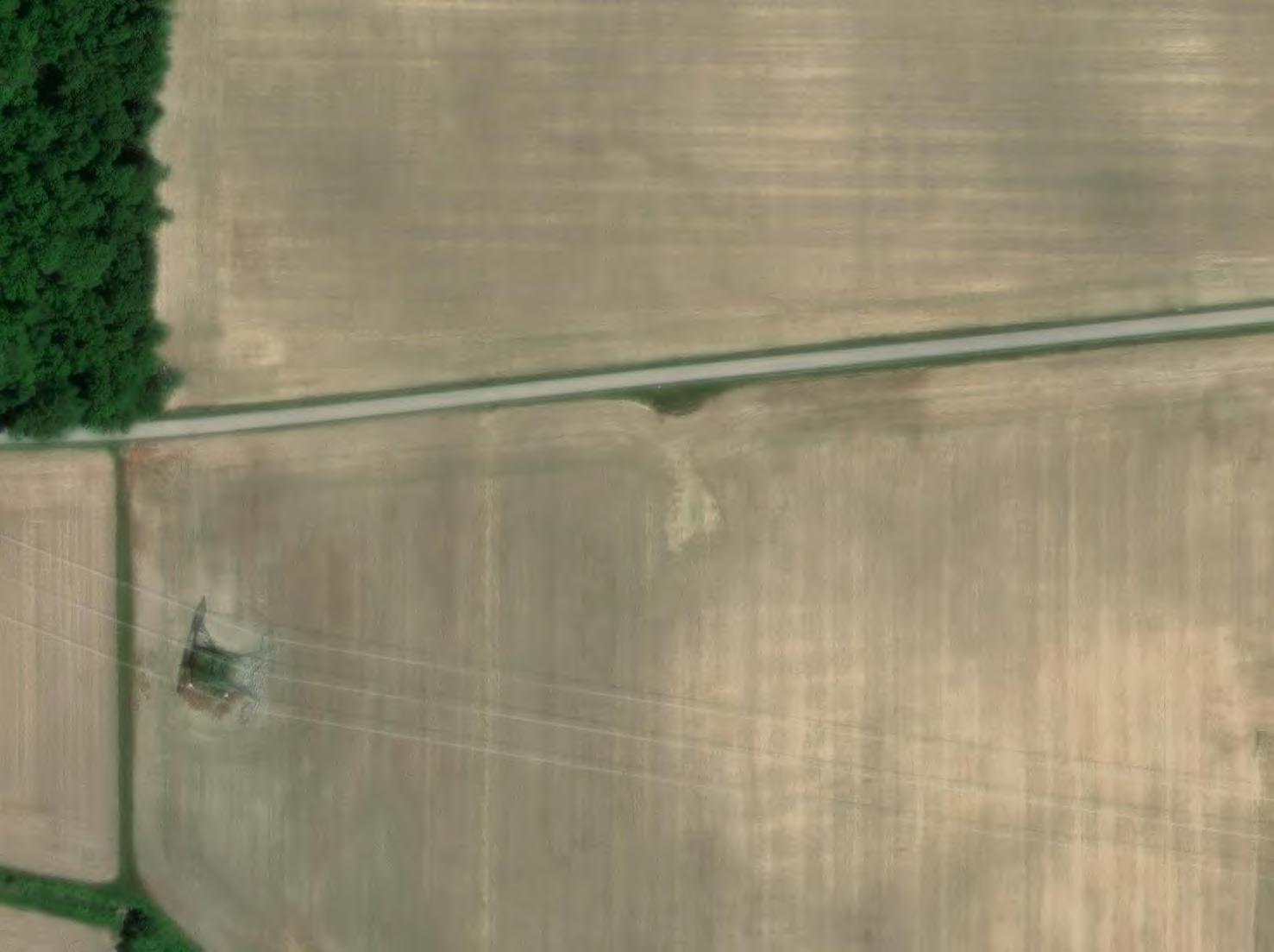
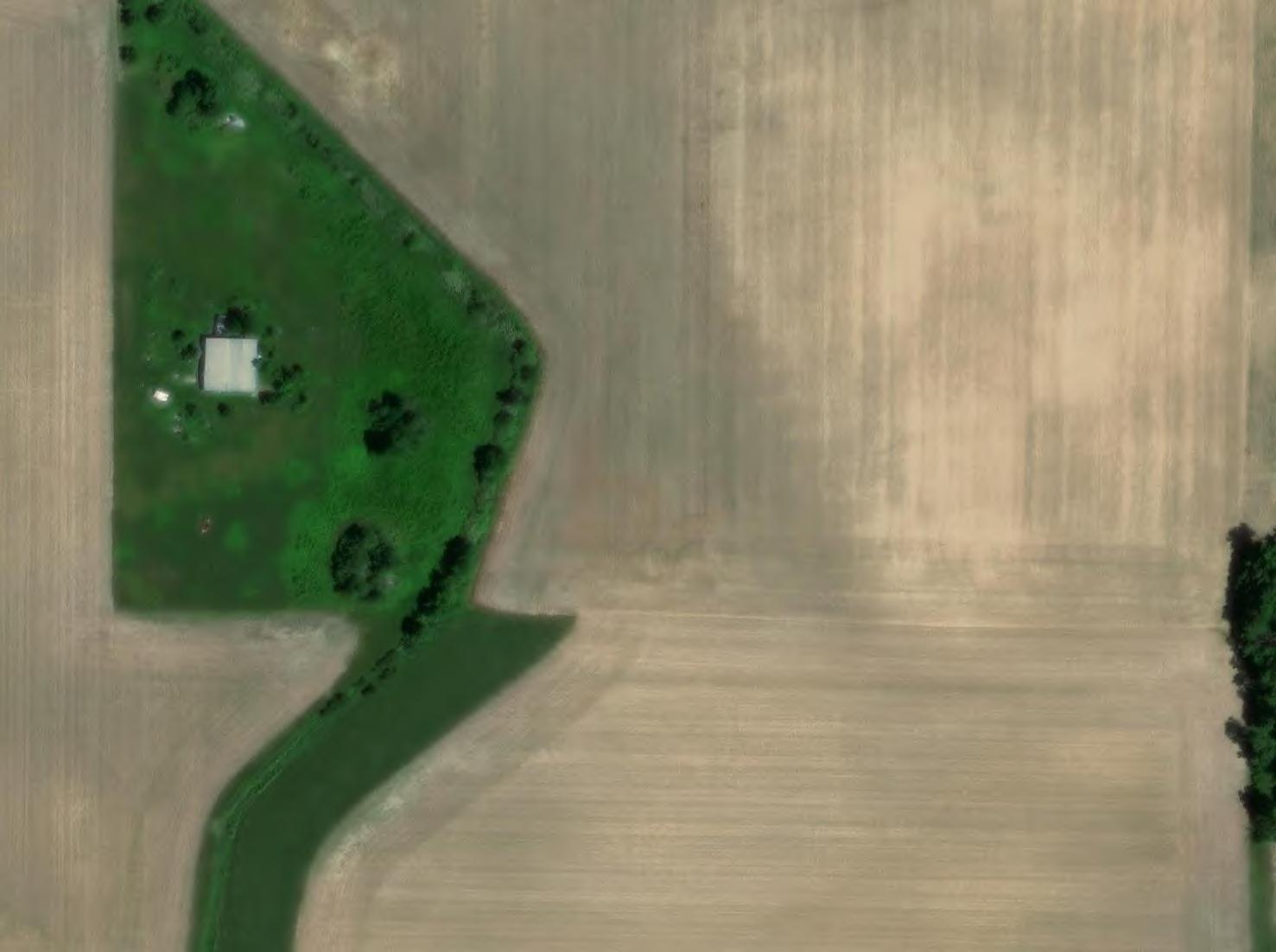
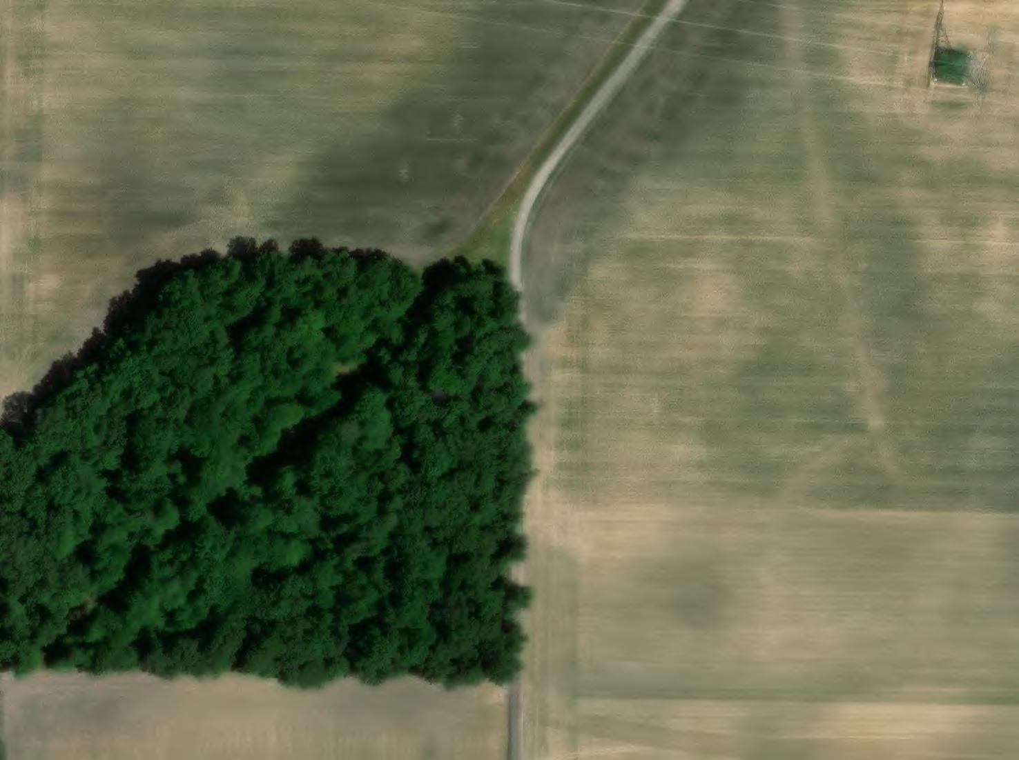
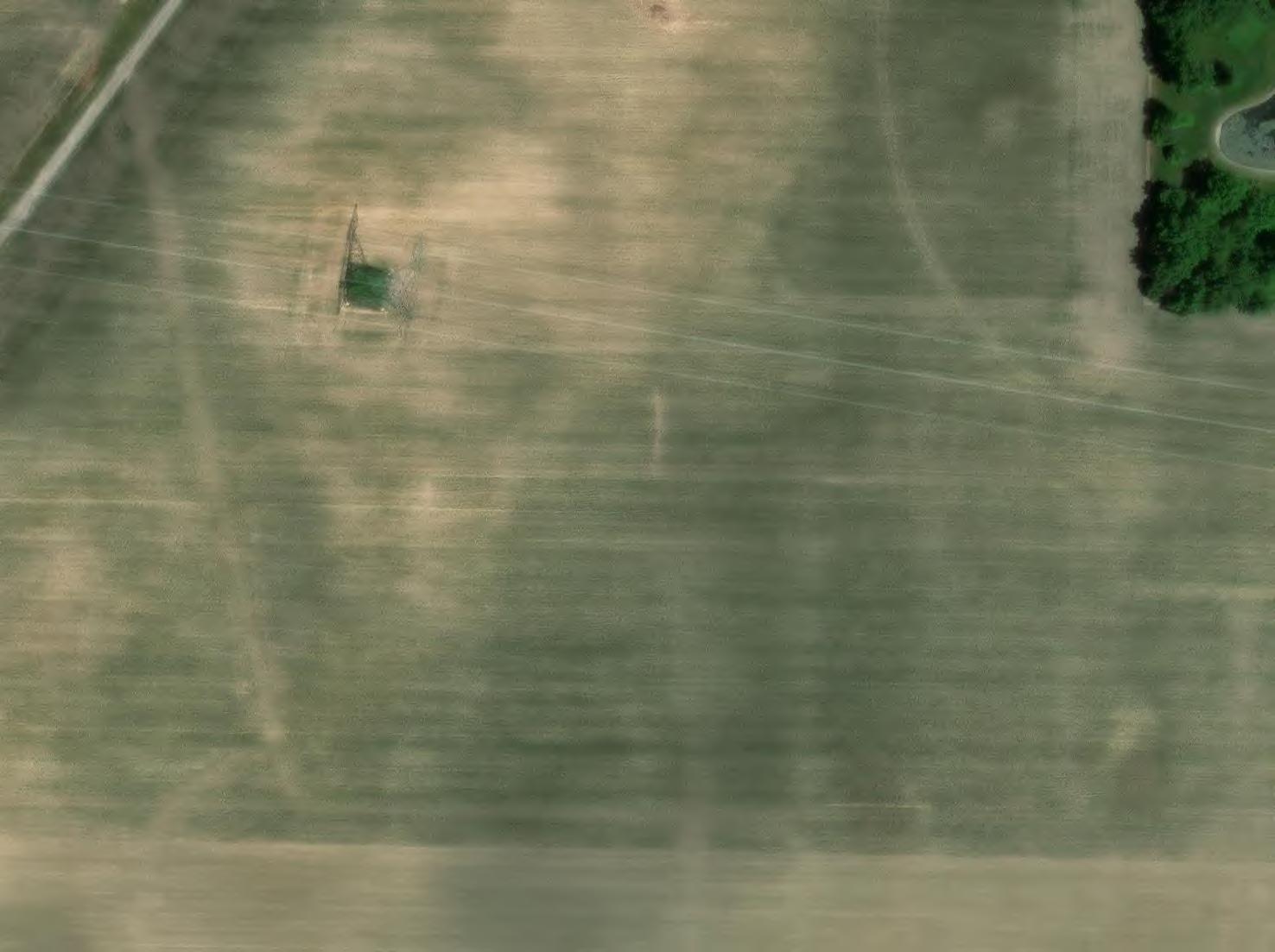
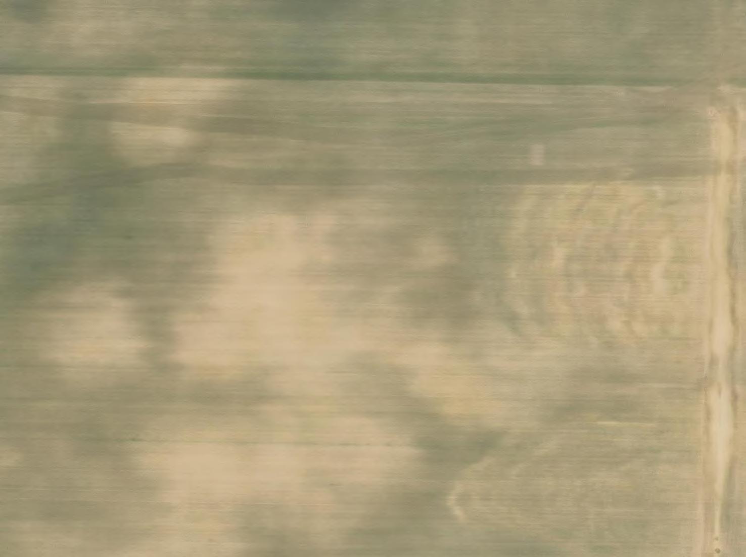
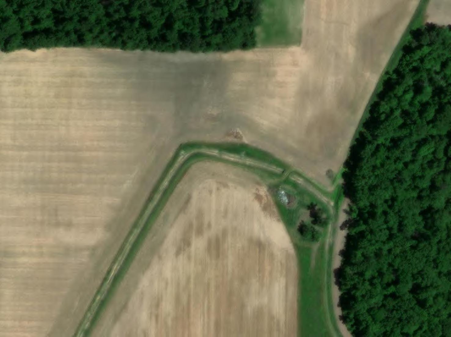
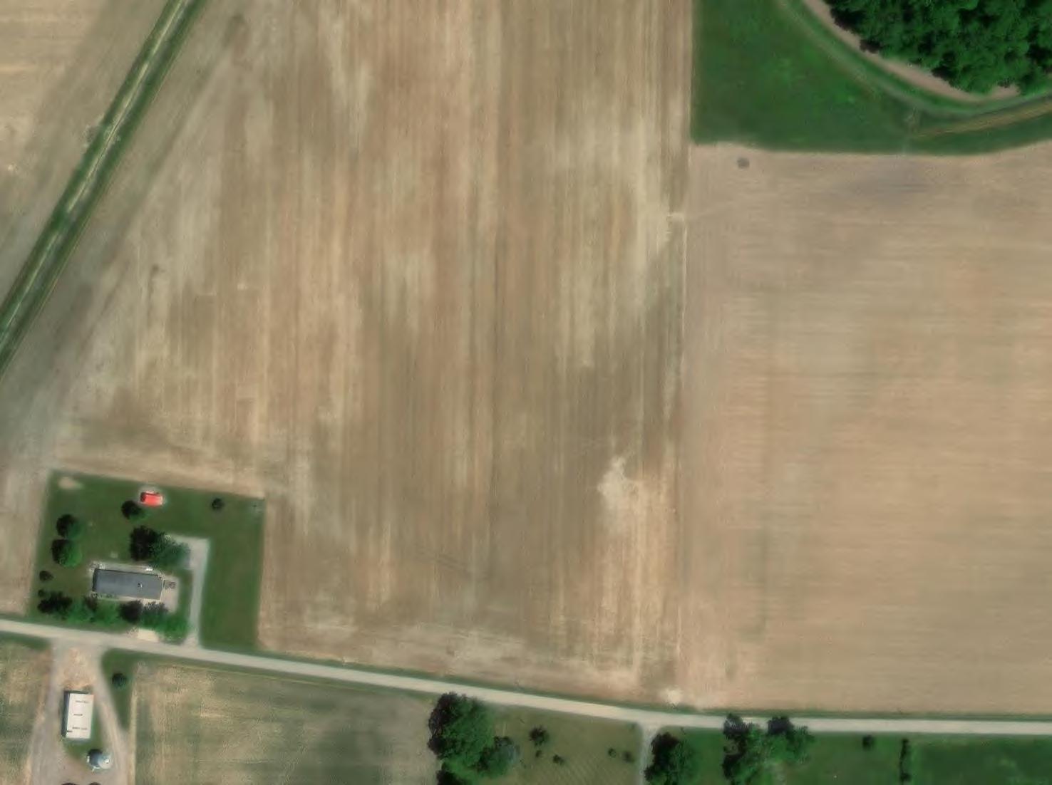
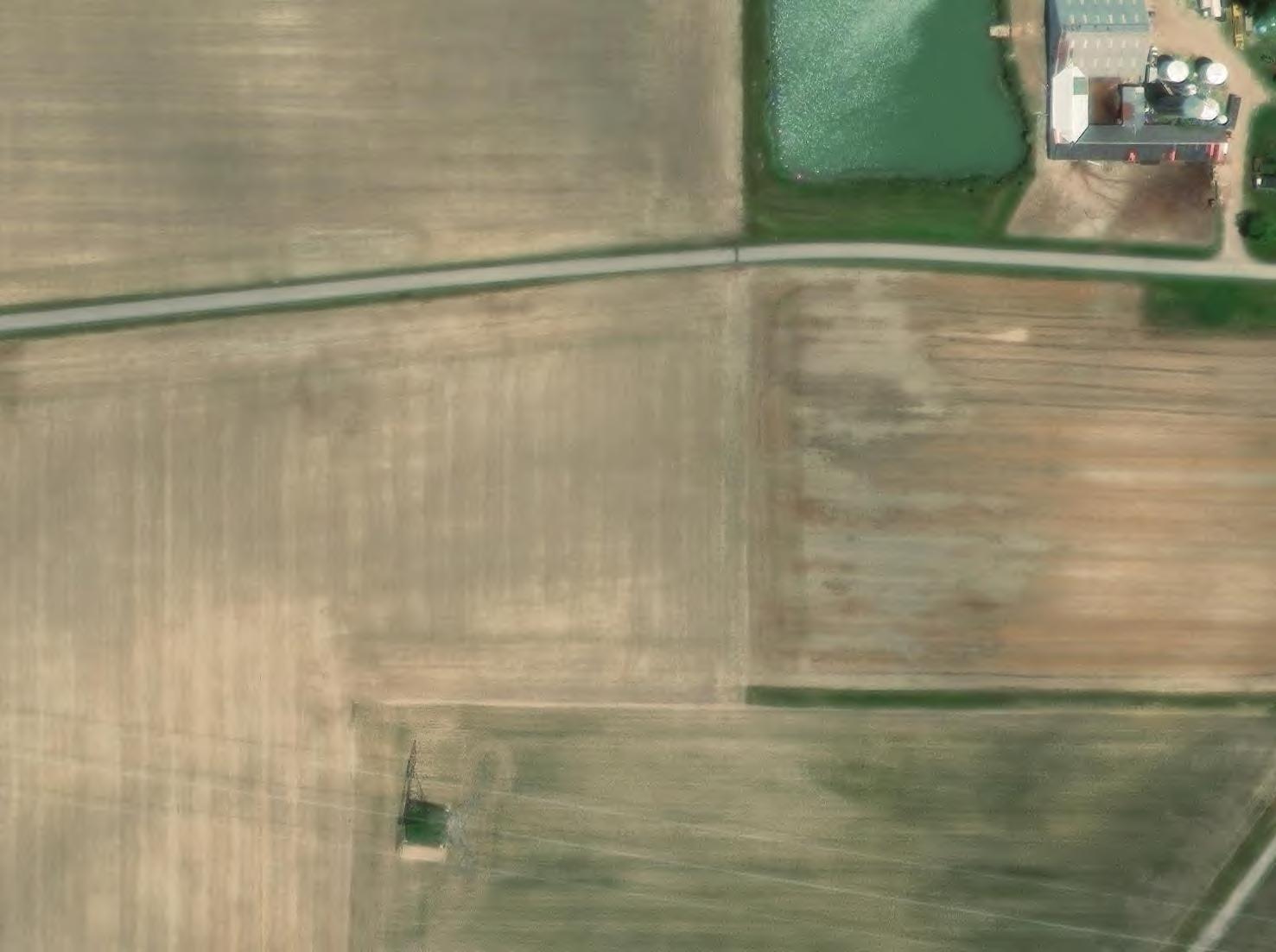
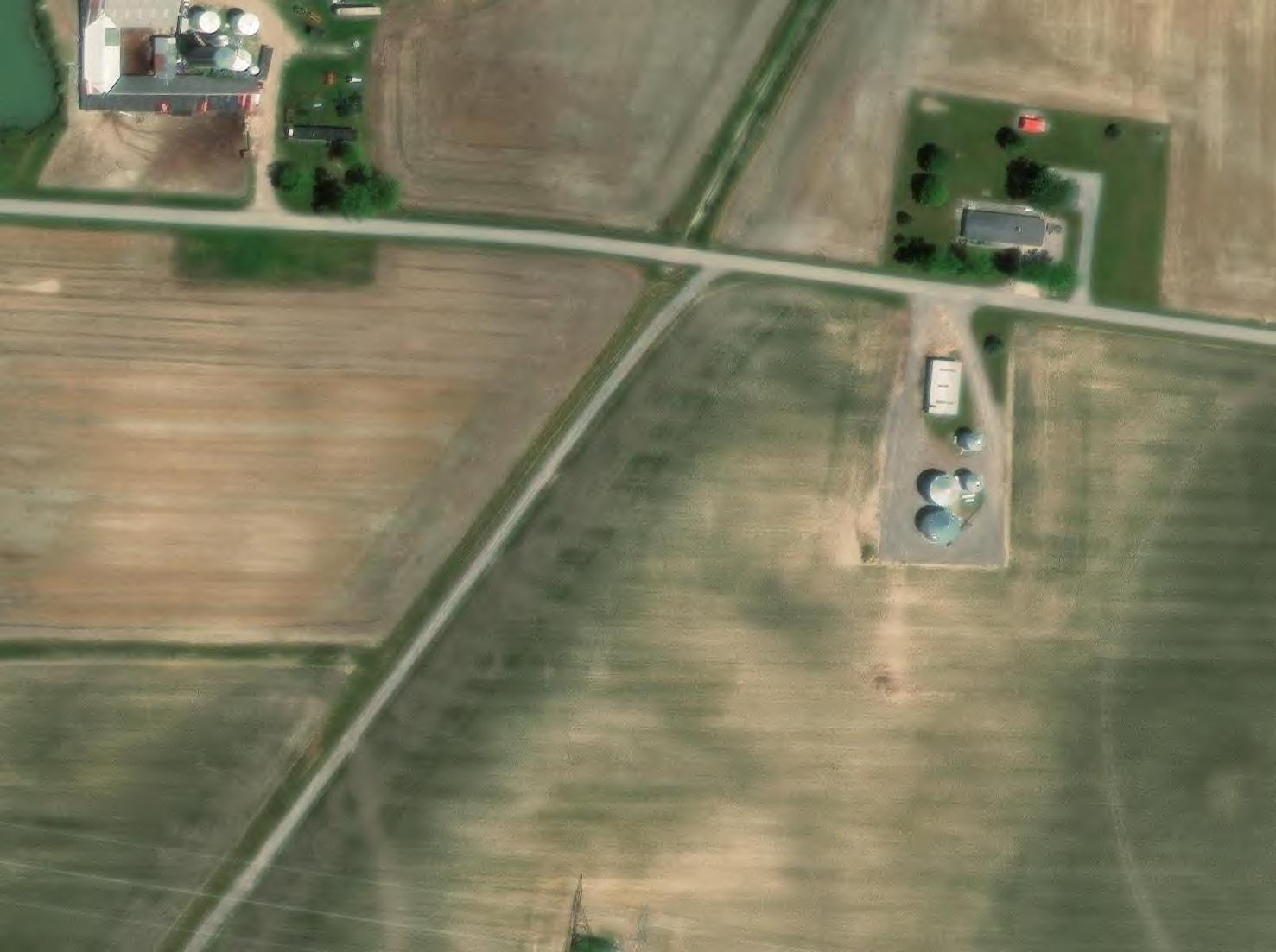
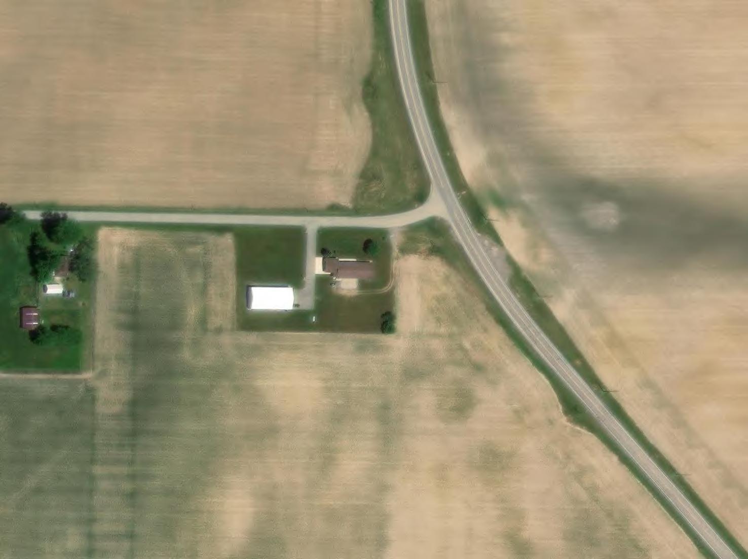
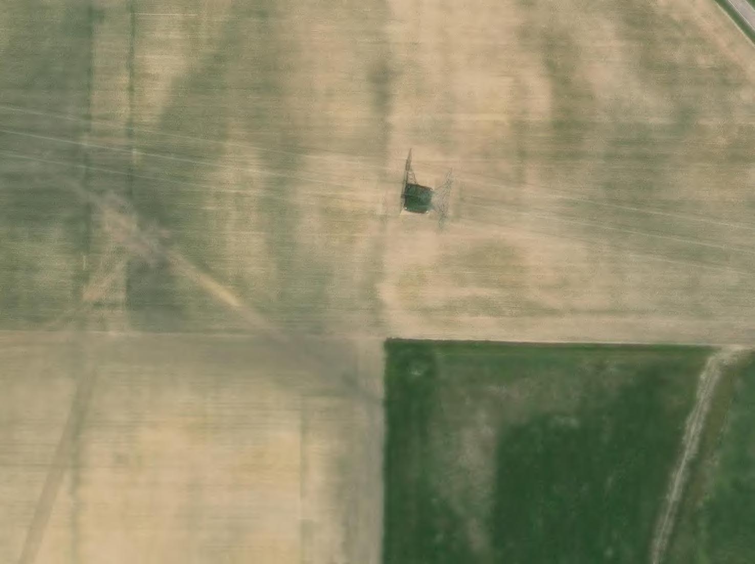
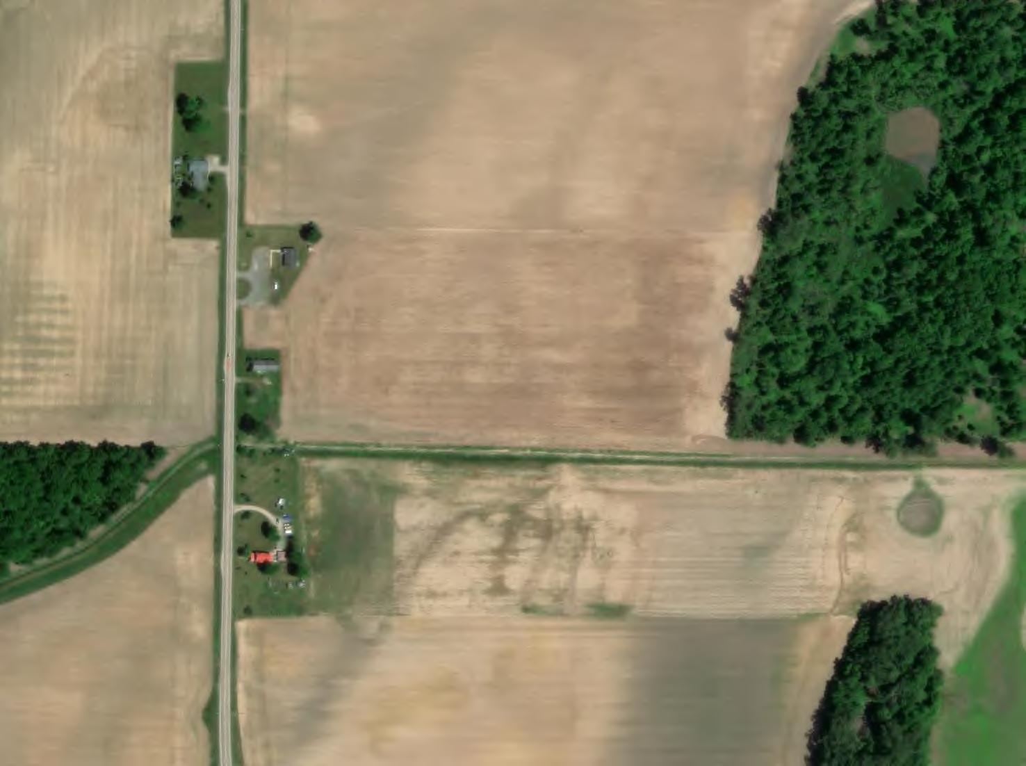
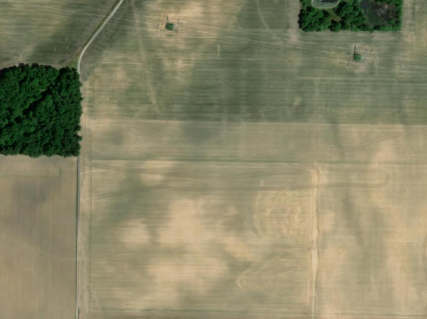
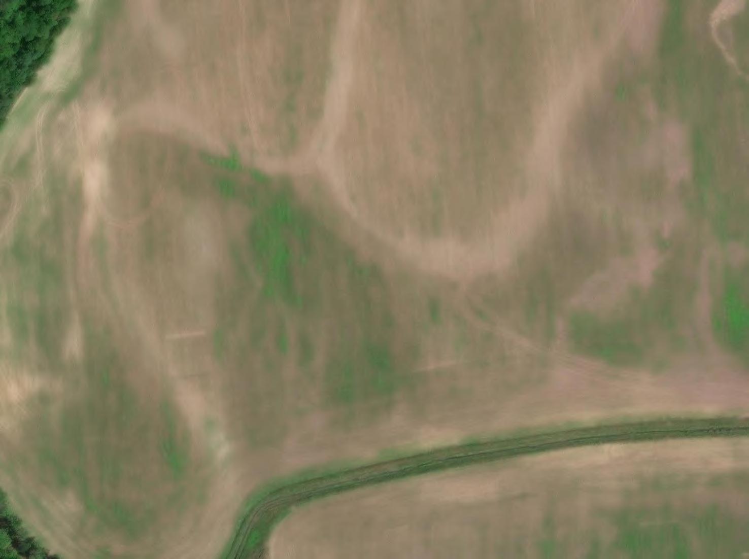
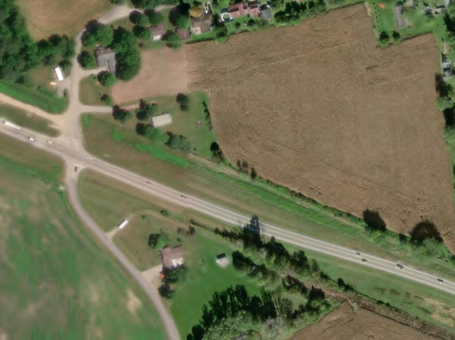
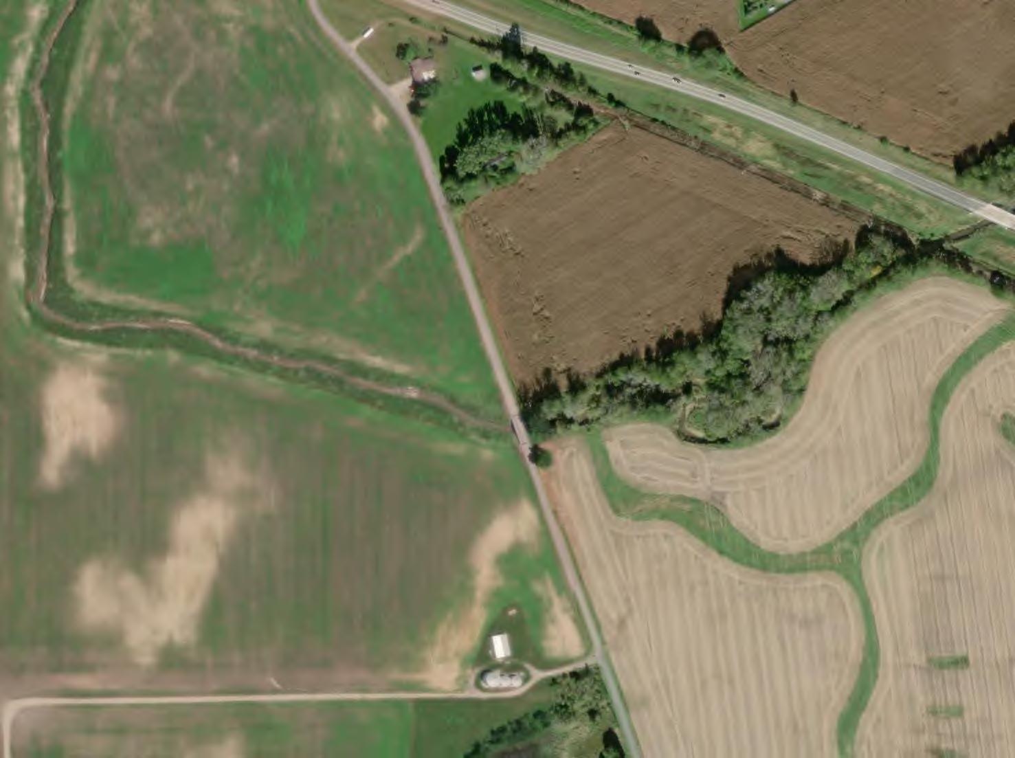
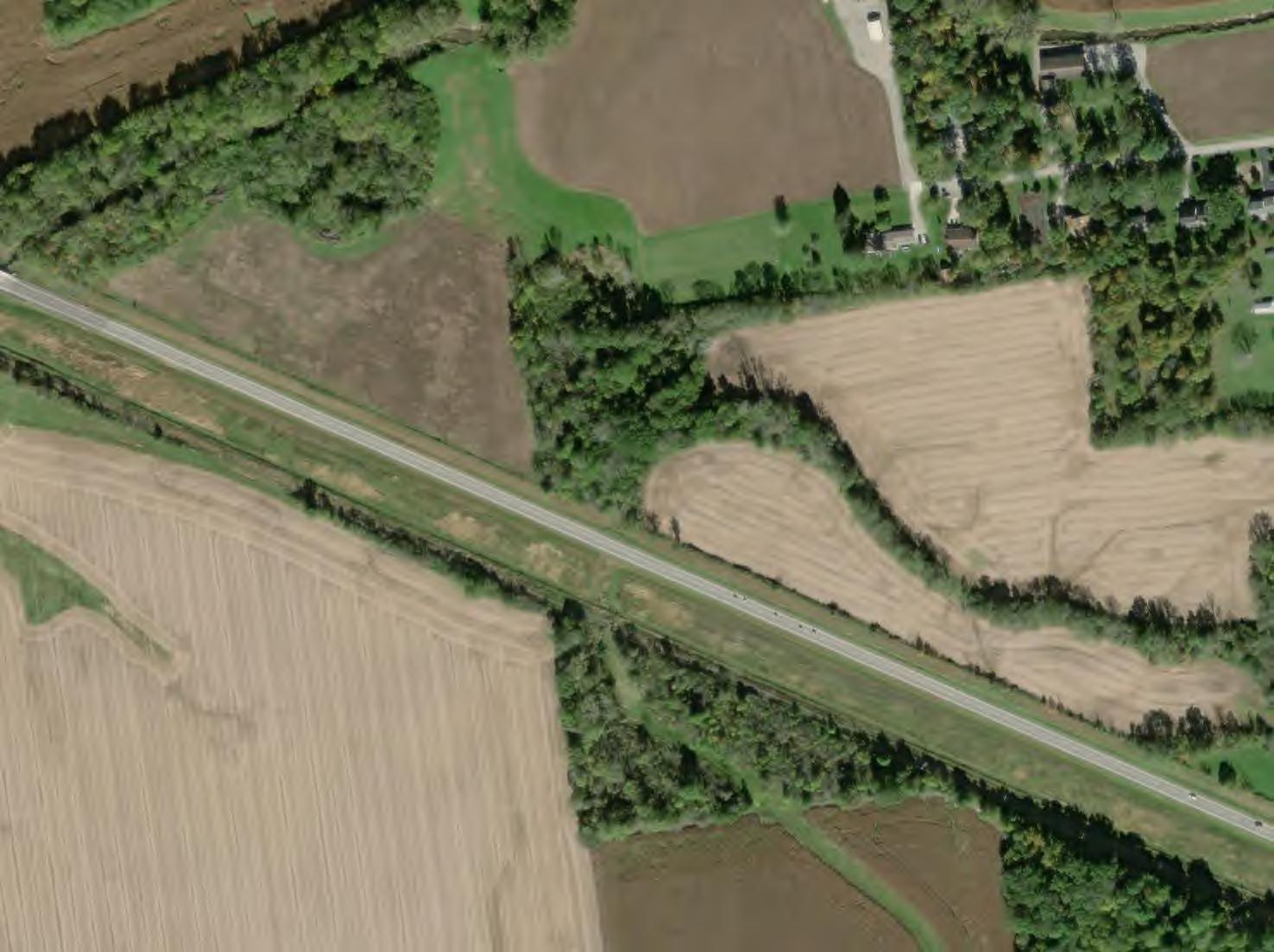
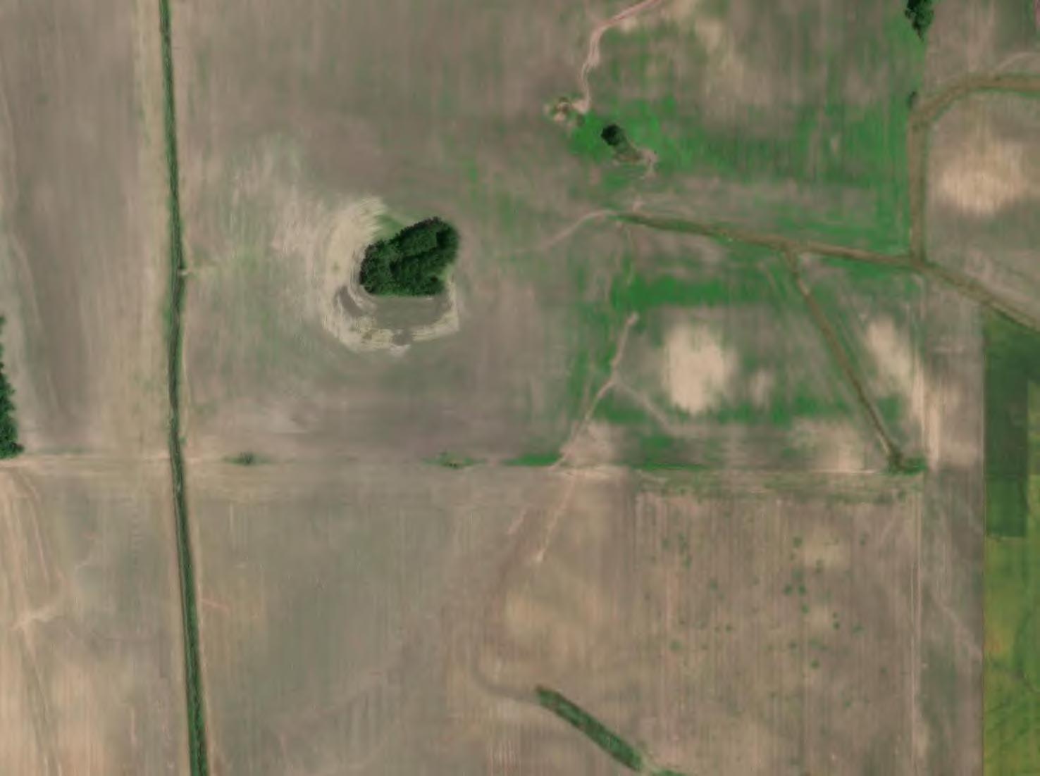
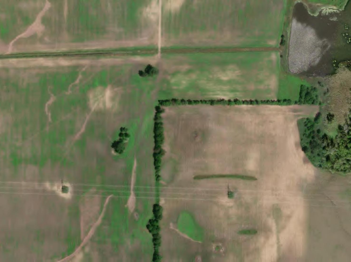
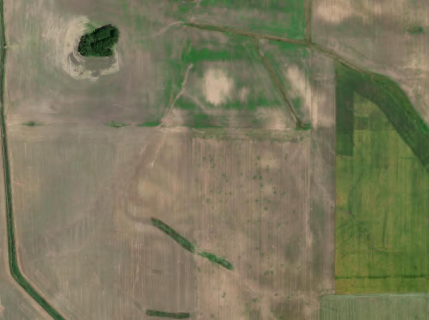
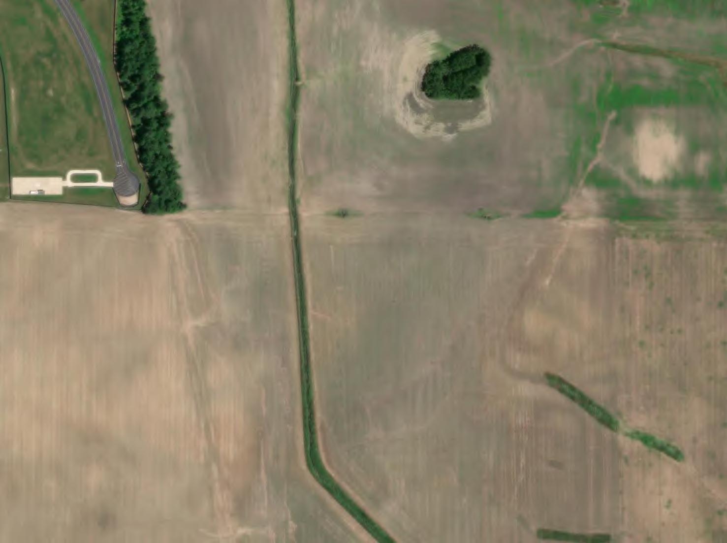
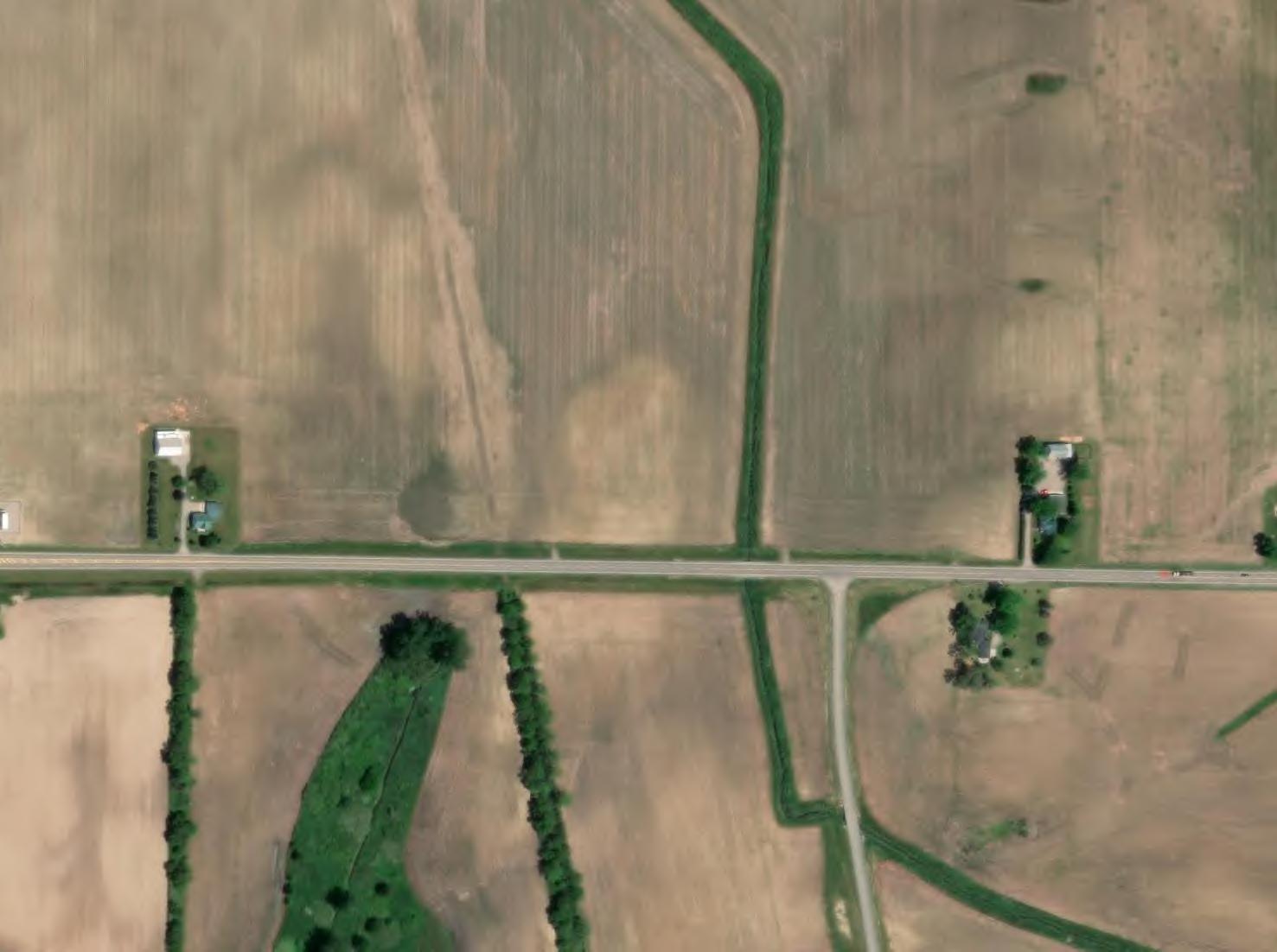
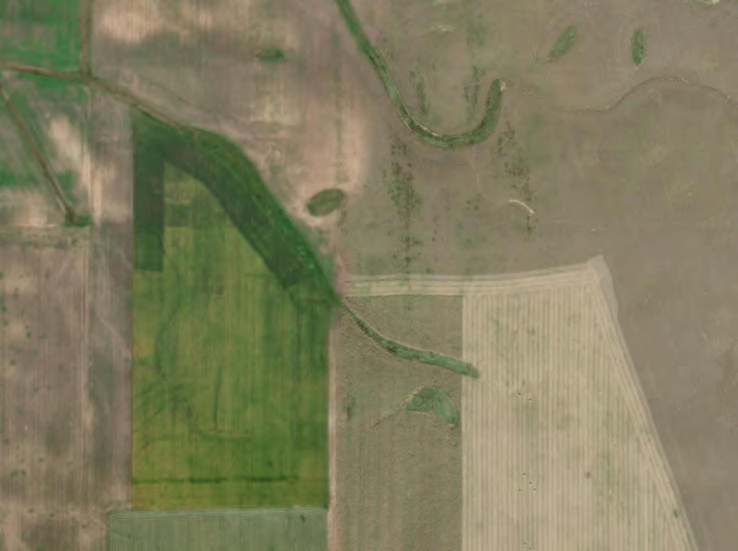
1. An aerial image taken at the right time of year can provide a visual indicator of the presence of drain tile. Dark colored soil dries out faster above drain tile resulting in a lighter color. A review of available aerial images can produce approximate locations of existing tile.
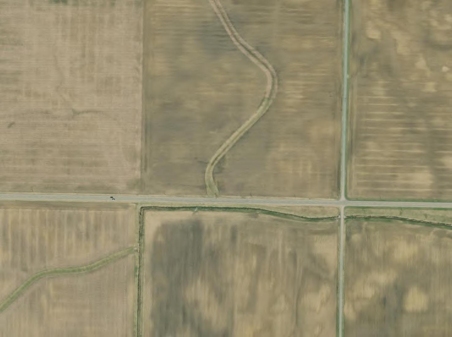
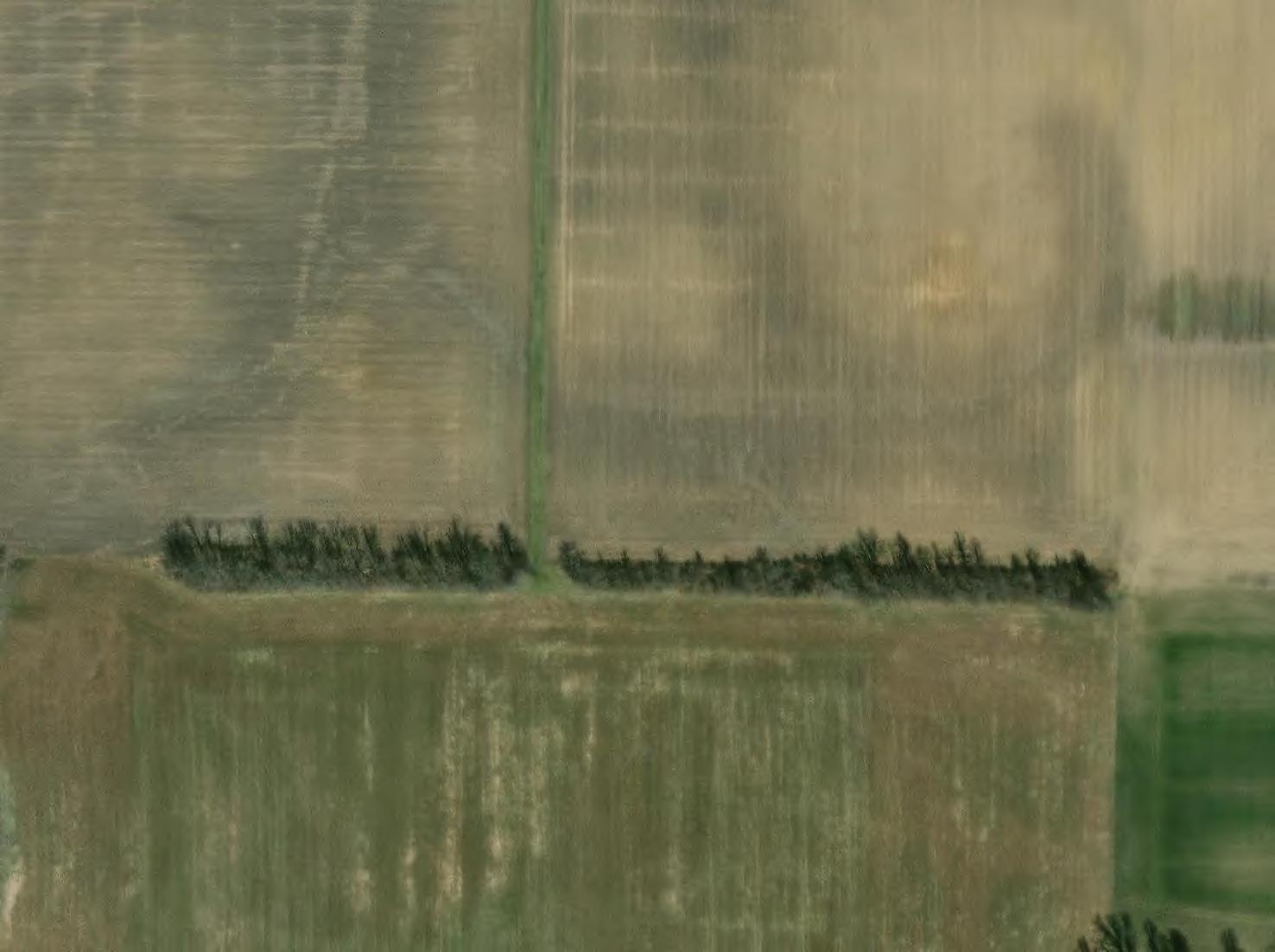
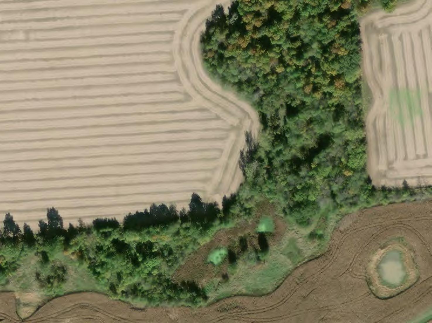
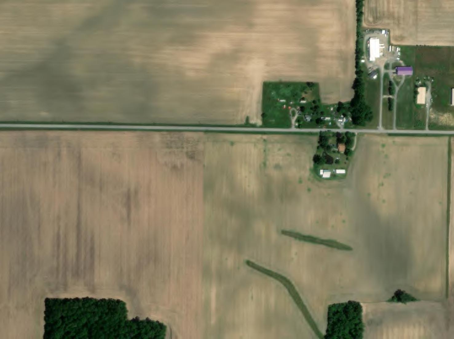
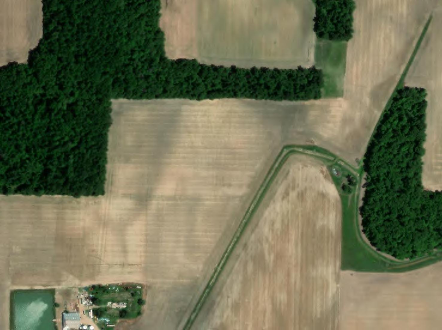
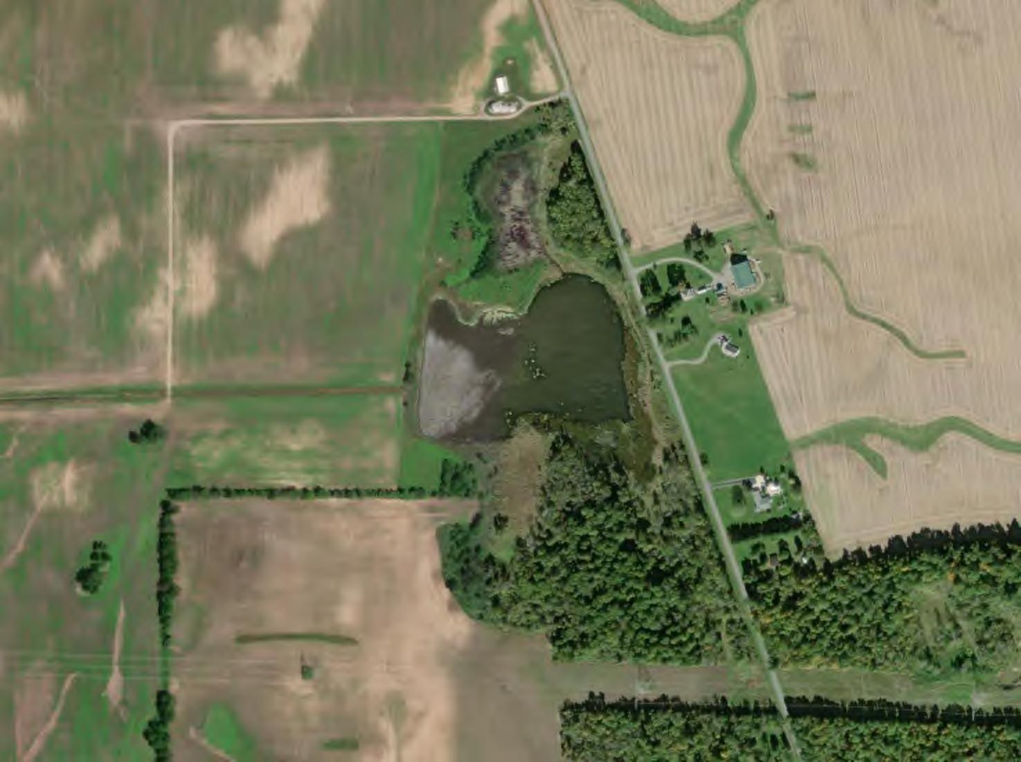
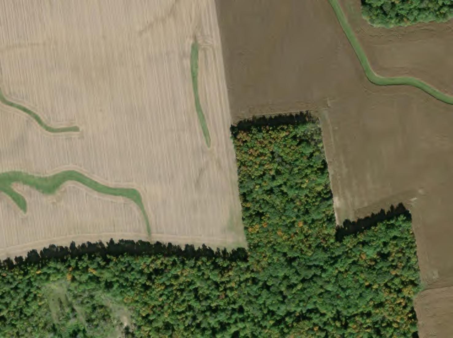
2. Grassed swales through fields may also have drain tile along their alignment. Aerial images can be used to map grassed swales which can then be verified as containing drain tile through other physical identification methods.
Jeffry Billenstein, with Ag Land Drain Til LLC, a drainage contractor and consultant, reviewed the information prepared from the above sources and visited the Study Area to review conditions at the site and consult with several landowners.
The data obtained during this assessment was used to compile a spatial dataset of known and suspected drain tile in and around the Study Area. The data was compiled using

ESRI’s ArcMap, version 10.8.1. Figure 1 is a Study Area Map and identifies the location of known or probable drain tile locations on project parcels.
Inlets/Outlets
Some drain tiles have inlets that are marked by the presence of a brightly colored riser, field marker, or protective grate at the inlet. Drain tile outlets can be identified by visually locating the pipe in a drainage swale or stream.
Soil Subsidence
As runoff infiltrates into the perforated drain tile, it can carry a small amount of soil with it. Over time, when enough soil has been transported into the pipe, small subsidence pockets become visible at the surface. If a drain tile is suspected in a location, visually locating these subsidence pockets over the suspected route can verify the presence of the tile.
Topography
Drain tile (in particular, a drain tile main) is typically located in low areas or follows existing drainage paths. Evaluating existing topography provides some insight into the likely location of drain tile by identifying low, poorly drained areas and natural flow paths that would provide the easiest route for a drain tile. Topography is also used to identify which adjacent properties would be “upstream” of the Study Area and therefore, the most likely to be affected by changes in the drain tile system within the Study Area.
Physical exploration methods, like those described below, are typically completed during a facility’s final design stage and during construction. Once the probable drain tile locations or routes are identified using the methods above, the following methods could be used to physically locate the drain tile which allows the location to be marked and surveyed so that it can be added to a map as an accurate representation of drain tile routing.
Using an excavator or other small piece of equipment, trenches can be excavated perpendicular to the suspected drain tile route until the pipe is exposed.
Using a T-handled steel rod during soft soil conditions, the steel rod can be pressed vertically down into the soil where the drain tile is suspected to be located. When the rod hits a tile, the spot is marked and surveyed.
Maverick Tile Finder
A flexible rod can be inserted into the drain tile at a known location. A copper wire is embedded in the rod that sends a signal to a locator on the surface. The locator can traverse the approximate drain tile route on the surface and when a positive signal is encountered, the location can be marked and surveyed.

Verdantas has performed its services using that degree of care and skill ordinarily exercised under similar conditions by reputable members of its profession practicing in the same or similar locality at the time of service. No other warranty, expressed or implied, is made or intended by our proposal or by our oral or written reports. The work does not attempt to evaluate past or present compliance with federal, state, or local environmental or land use laws or regulations. Conclusions presented by Verdantas regarding the area within the Study Area are consistent with the Scope of Work, level of effort specified, and investigative techniques employed. Reports, opinions, letters, and other documents do not evaluate the presence or absence of any condition not specifically analyzed and reported. Verdantas makes no guarantees regarding the completeness or accuracy of any information obtained from public or private files or information provided by subcontractors.


