EXHIBIT B
Representative Component Models
APPLICATION TO THE OHIO POWER SITING BOARD FOR A
CERTIFICATE OF ENVIRONMENTAL COMPATIBILITY AND PUBLIC NEED FOR THE
Case No. 24-0801-EL -BGN


APPLICATION TO THE OHIO POWER SITING BOARD FOR A
CERTIFICATE OF ENVIRONMENTAL COMPATIBILITY AND PUBLIC NEED FOR THE
Case No. 24-0801-EL -BGN

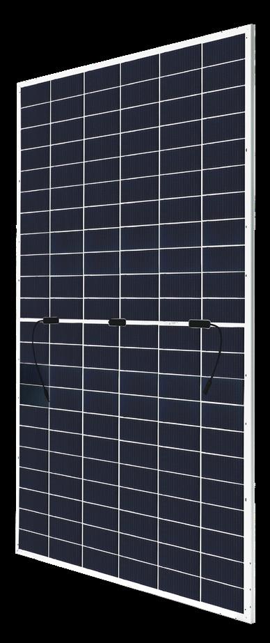
CS7N-690|695|700|705|710|715|720TB-AG
MORE POWER
Module power up to 720 W
720 W
EXTRA POWER
Module efficiency up to 23.2 %
Up to 85% Power Bifaciality, more power from the back side
Excellent anti-LeTID & anti-PID performance.
Low power degradation, high energy yield

Lower temperature coefficient (Pmax): -0.29%/°C, increases energy yield in hot climate
Lower LCOE & system cost
MORE RELIABLE
Tested up to ice ball of 35 mm diameter according to IEC 61215 standard
Heavy snow load up to 5400 Pa, wind load up to 2400 Pa* Minimizes micro-crack impacts
* For detailed information, please refer to the Installation Manual.
CSI Solar Co., Ltd.

Enhanced Product Warranty on Materials and Workmanship*
Linear Power Performance Warranty*
1st year power degradation no more than 1%
Subsequent annual power degradation no more than 0.4%
*According to the applicable Canadian Solar Limited Warranty Statement.
MANAGEMENT SYSTEM CERTIFICATES*
ISO 9001: 2015 / Quality management system
ISO 14001: 2015 / Standards for environmental management system
ISO 45001: 2018 / International standards for occupational health & safety
IEC 62941: 2019 / Photovoltaic module manufacturing quality system
PRODUCT CERTIFICATES*
IEC 61215 / IEC 61730 / CE / INMETRO / MCS / UKCA / CGC
CEC listed (US California) / FSEC (US Florida)
UL 61730 / IEC 61701 / IEC 62716 / IEC 60068-2-68
UNI 9177 Reaction to Fire: Class 1 / Take-e-way


* The specific certificates applicable to different module types and markets will vary, and therefore not all of the certifications listed herein will simultaneously apply to the products you order or use. Please contact your local Canadian Solar sales representative to confirm the specific certificates available for your Product and applicable in the regions in which the products will be used.
CSI Solar Co., Ltd. is committed to providing high quality solar photovoltaic modules, solar energy and battery storage solutions to customers. The company was recognized as the No. 1 module supplier for quality and performance/price ratio in the IHS Module Customer Insight Survey. Over the past 23 years, it has successfully delivered over 125 GW of premium-quality solar modules across the world.
199 Lushan Road, SND, Suzhou, Jiangsu, China, 215129, www.csisolar.com, support@csisolar.com
Mounting Hole
Gain**
834 W 39.8 V 20.96 A 47.7 V 22.13 A 26.8%
CS7N-700TB-AG 700 W 40.0 V 17.51 A 47.9 V 18.49 A
Bifacial Gain** 5% 735 W 40.0 V 18.39 A 47.9 V 19.41 A 23.7%
W 40.0 V 19.26 A 47.9 V 20.34 A
840 W 40.0 V 21.01 A 47.9 V 22.19 A 27.0%
CS7N-705TB-AG 705 W 40.2 V 17.55 A 48.1 V 18.54 A 22.7%
Bifacial Gain**
5% 740 W 40.2 V 18.43 A 48.1 V 19.47 A 23.8% 10% 776 W 40.2 V 19.31 A 48.1 V 20.39 A 25.0% 20% 846 W 40.2 V 21.06 A 48.1 V 22.25 A 27.2%
CS7N-710TB-AG 710 W 40.4 V 17.59 A 48.3 V 18.59 A 22.9%
Bifacial Gain**
5% 746 W 40.4 V 18.47 A 48.3 V 19.52 A 24.0% 10% 781 W 40.4 V 19.35 A 48.3 V 20.45 A 25.1% 20% 852 W 40.4 V 21.11 A 48.3 V 22.31 A 27.4%
CS7N-715TB-AG 715 W 40.6 V 17.63 A 48.5 V 18.64 A 23.0%
Bifacial Gain**
751 W 40.6 V 18.51 A 48.5 V 19.57 A
787 W 40.6 V 19.39 A 48.5 V 20.50 A
20% 858 W 40.6 V 21.16 A 48.5 V 22.37 A 27.6%
CS7N-720TB-AG 720 W 40.8 V 17.67 A 48.7 V 18.69 A 23.2%
Bifacial Gain** 5% 756 W 40.8 V 18.55 A 48.7 V 19.62 A 24.3%
792 W 40.8 V 19.44 A 48.7 V 20.56 A
864 W 40.8 V 21.20 A 48.7 V 22.43 A 27.8% * Under Standard Test Conditions (STC) of irradiance of 1000 W/m2, spectrum AM 1.5 and cell temperature of 25°C. ** Bifacial Gain: The additional gain from the back side compared to the power of the front side at the standard test condition. It depends on mounting (structure, height, tilt angle etc.) and albedo of the ground.
ELECTRICAL DATA
Operating Temperature -40°C ~ +85°C
Max. System Voltage 1500 V (IEC/UL)
Module Fire Performance TYPE 29 (UL 61730) or CLASS C (IEC61730)
Max. Series Fuse Rating 35 A
Protection Class Class II
Power Tolerance
Power Bifaciality* 80 %
* Power Bifaciality = Pmaxrear / Pmaxfront, both Pmaxrear and Pmaxfront are tested under STC, Bifaciality
Tolerance: ± 5 %
* The specifications and key features contained in this datasheet may deviate slightly from our actu
al products due to the on-going innovation and product enhancement. CSI Solar Co., Ltd. reserves the right to make necessary adjustment to the information described herein at any time without further notice.
Please be kindly advised that PV modules should be handled and installed by qualified people who have professional skills and please carefully read the safety and installation instructions before using our PV modules.
CS7N-690TB-AG 522 W
V
A
V
A
CS7N-695TB-AG 526 W 37.6 V 13.97 A 45.2 V 14.87 A
CS7N-700TB-AG
CS7N-715TB-AG 541 W 38.4 V 14.09 A 45.9 V 15.03 A
CS7N-720TB-AG
* Under Nominal Module Operating Temperature (NMOT), irradiance of 800 W/m2,
trum AM 1.5, ambient temperature 20°C, wind speed 1 m/s.
MECHANICAL DATA
Specification Data
Cell Type TOPCon cells
Cell Arrangement 132 [2 x (11 x 6) ]
Weight 37.8 kg (83.3 lbs)
Front Glass 2.0 mm heat strengthened glass with antireflective coating
Back Glass 2.0 mm heat strengthened glass
Frame Anodized aluminium alloy
J-Box IP68, 3 bypass diodes
Cable 4.0 mm² (IEC), 12 AWG (UL)
Cable Length (Including Connector) 360 mm (14.2 in) (+) / 200 mm (7.9 in) (-) or customized length*
Connector T6 or MC4-EVO2 or MC4-EVO2A
Per Pallet 33 pieces
Per Container (40' HQ) 594 pieces or 495 pieces (only for US & Canada)
* For detailed information, please contact your local Canadian Solar sales and technical representatives.
TEMPERATURE CHARACTERISTICS
Specification Data
Temperature Coefficient (Pmax) -0.29 % / °C
Temperature Coefficient (Voc) -0.25 % / °C
Temperature Coefficient (Isc) 0.05 % / °C
Nominal Module Operating Temperature 41 ± 3°C
PARTNER SECTION
Forprofessionaluseonly


This general manual provides important safety informationrelatingtotheinstallation,maintenance,and handlingofCanadianSolarmodules
Professional installers must read these guidelines carefully and strictly follow these instructions. Failure to follow these instructions may result in death, injury, or property damage. The installation and handling of PV modules require professional skills and should only be
Singleglass
CS6L-MS,CS6R-MS
CS6RA-MS,CS6RB-MS
CS6R-MS-HL
performed by qualified professionals. Installers must inform end-users (consumers) of the aforesaid informationaccordingly.
The word “module” or “PV module” used in this manual refers to one or more Canadian Solar modules. This manual is valid for the solar modules listed in the table below.Pleaseretainthismanualforfuturereference. We recommend visiting www.csisolar.com regularly for the mostupdatedversionofthisinstallationmanual.
Monofacial
Bifacial
CS6W-MS,CS6W-T,CS6R-T,CS6.1-42TM
CS6.1-54TM-H
CS6.1-60TM,CS6.1-60TM-H
CS6.2-32TM,CS6.2-36TM
CS6.2-48TM,CS6.2-54TM
CS7L-MS,CS7N-MS
CS6R-MB-HL
AllabovemoduletypesincludeIEC1000VandIEC1500Vversions.
The information contained in this manual is subject to changebyCanadianSolarwithoutpriornotice.Canadian Solar gives no warranty of any kind whatsoever, either explicitly or implicitly, with respect to the information containedherein.
In the event of any inconsistency among different language versions of this document, the English version shall prevail. Please refer to our product lists and documentspublishedonourwebsiteatwww.csisolar.com astheselistsareupdatedonaregularbasis
Canadian Solar shall not be held responsible for any productdefectsordamages,bodilyharm,personalinjury,
CS6R-H-AG
CS6.1-72TD
CS6.1-54TD
CS6.2-48TD
CS6W-MB-AG,CS6W-TB-AG
CS7-60HB,CS7-66HB
CS7L-MB-AG,CS7N-MB-AG
CS7L-TB-AG,CS7N-TB-AG
CS6.1-54TB,CS6.1-60TB
CS6.1-72TB,CS6.1-72TB-H
CS6.2-66TB
or property damage, in connection with handling PV modules, system installation, or compliance or noncompliancewiththeinstructionssetforthinthismanual, exceptasotherwiseprovidedbylaw.

WARNING
Before attempting to install, wire, operate, and/or service the module and other electrical equipment, all instructions should be read and understood. PV module connectors pass direct current (DC) when exposed to sunlight or other light sources. Contact with electrically active parts of the module, such as terminals, can result in injury or death, irrespective of whether or not the module and the other electrical equipmenthavebeenconnected

Toutes les instructions devront être lues et comprisesavantdeprocéderàl’installation, lecâblage,l’exploitationet/oul’entretiendespanneaux. Lesinterconnexionsdespanneauxconduisentducourant continu (CC) lorsque le panneau est exposé à la lumière du soleil ou à d’autres sources lumineuses. Tout contact avecdesélémentssous tensiondupanneautelsqueses bornesdesortiepeutentraînerdesblessuresoulamort, quelepanneausoitconnectéounon.
All modules must be installed by licensed electricians in accordance with the applicable electrical codes such as the latest National Electrical Code (USA) or Canadian Electric Code (Canada), or other national or international applicableelectricalcodes.


Protectiveclothing(non-slipgloves,clothes, etc.) must be worn during installation and maintenancetopreventdirectcontactwith 30VDC orgreater,andtoprotecthandsfrom sharp edges. Do not touch any damaged area,suchasburnmarks,oranywherewith an exposed conductor to avoid the risk of electricshock.
Prior to installation, remove all metallic jewelry to prevent accidental exposure to livecircuits.
When installing modules in light rain, or morning dew, take appropriate measures topreventwateringressintotheconnector.
Do not allow children or unauthorized personsneartheinstallationsiteormodule storagearea.
Use electrically insulated tools to reduce the risk of electricshock.
If the disconnects and over-current protection devices (OCPDs) cannot be opened or the inverter cannot be powered down, cover the fronts of the modules in the PV array with an opaque material to stop the production of electricity when installing or working on amoduleorwiring.
Donotinstallmodulesinstrongwind.
Donotuseorinstallbrokenmodules
Do not contact the module surface if the front or rear glassisbroken.Thismaycauseelectricshock.
Donotattempttorepairanypartofthemodule.ThePV moduledoesnotcontainanyserviceableparts.
Donotopenthecoverofthejunctionboxatanytime.
Do not disassemble a module or remove any module part
Donotartificiallyconcentratesunlightonamodule.
Do not connect or disconnect modules when current fromthemodulesoranexternalsourceispresent.
When the inverter gives a grounding alarm, please wear personal protective equipment first and make sureitissafebeforedisconnectingtheinverterandthe faulty modules. Do not touch any other parts of the moduletoavoidelectricshock.
Module electrical ratings are measured under Standard Test Conditions (STC) of 1000 W/m2 irradiance, with an AM1.5spectrum,andacelltemperatureof25°C.Detailed electrical and mechanical characteristics of Canadian Solar crystalline silicon PV modules can be found in datasheets and on www.csisolar.com. The main electrical characteristicsatSTCandatbifacialnameplateirradiance (BNPI)arealso stated oneachmodulelabel. Pleaserefer to the datasheet or the product nameplate for the maximumsystemvoltage.
Under certain conditions, a module may produce more currentorvoltagethanitsStandardTestConditionsrated power.Asaresult,electricalcalculationsanddesignmust beperformedbyaqualifiedengineerorconsultant.
A correction factor should be applied to the open-circuit voltage (see Table 1 below), when determining componentratingsandcapacities.
Table1:Low-temperaturecorrectionfactorsforopencircuitvoltage
selectedmodule(refertothecorrespondingdatasheet) Please contact Canadian Solar’s technical support team foramoreaccuratecorrectionfactorifnecessary.
The module short-circuit current under STC should be multiplied by 1.25×1.25 (i.e., 1.56), when determining appropriate wire and fuse specifications. For bifacial modules, short-circuit current is related to specific installation conditions. It varies with different mounting heightsandmountingsurfaceswithdifferentreflectivity
Consequently short-circuit current of bifacial modules shouldbemultipliedby1.56andthenby1.2.Forbifacial modulesmountedclosetotheroofsurface,nosignificant bifacial gain can be obtained, and therefore, the 1.2 additionalcoefficientisnotapplicableandcanbeignored.
OCPD rating selection should be done per the following guidance, where the minimum OCPD rating possible is determinedbycalculatingtheexpectedmaximumcircuit currentforthePVsystem,andthemaximumOCPDrating constrained by the IEC 61215 and UL 61730 standard requirementsforthecertifiedPVmodules.
Formonofacialmodules,thestringfuseratingshouldnot exceed the maximum string fuse rating listed in the correspondingdatasheet.
For bifacial modules, the following method can be appliedtodetermineanappropriaterating(X):
Minimum string fuse rating < X ≤ Maximum string fuserating.
The maximum string fuse ratings can be found in datasheetsandnameplatesforallthecertifiedCanadian Solarmoduletypes.
TheminimumstringfuseratingforcompliancewithNEC: 2017codeandIEC62548:2016requirementissuggested tobedeterminedasfollows:
Minimumstringfuserating=IscSTC x1.25xMax(1.175, Imppα ÷ImppSTC).
Alternatively, the correction factor for the open-circuit voltagecanbecalculatedusingthefollowingformula:
T (°C) is the lowest expected ambient temperature at the systeminstallationsite
αVoc (%/°C) is the voltage temperature coefficient of the
Imppα = the highest 3-hour current average resulting from the simulated local simultaneous irradiances on thefront and rearsidesofthe PV array accounting for elevationandorientation.
IscSTC =thelistedshortcircuitcurrentat0%bifacialgain onthePVmoduledatasheetornameplatelabel.
ImppSTC = the listed MPP operating current at 0%
bifacialgainonthePVmoduledatasheetornameplate label.
Anassembly,togetherwithitsovercurrentdevice(s),that is listed for continuous operation at 100% of its rating shall be permitted to be used at 100% of its rating, and thereforeshallnotrequiretheadditional1.25multiplier.
Please contact Canadian Solar’s technical support team for additional information pertaining to engineering optimization and approval of project specific module stringlengths.

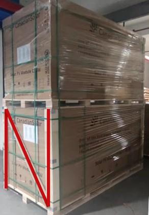
Modules should be stored in a dry and ventilated environment to avoid direct sunlight and moisture. If modules are stored in an uncontrolled environment, the storage time should be less than 3 months and extra precautions should be taken to prevent connectorsfrombeingexposedtomoistureorsunlight, likeusingconnectorendcaps.Protectthepackagefrom damage. In any circumstances, pallets with landscapeoriented module packaging shall not be stacked verticallymorethantwohigh;withtheN-bracketwood bracing installed on the bottom pallet for CS6-series modules(markedwithredlinesinthefollowingfigure) And for pallets with portrait-oriented module packaging,stackingisnotallowed
When unloading module pallets from containers, please use a forklift to remove the module pallets from the container or trailer. Do not move any pallets within the containerortrailerwithoutproperlyliftingthemfirst.The forkliftshouldbeclosetothegroundinordertoavoidthe topofmodulepalletsfromtouchingthetopofthecabinet door. The thickness of forklift blades should be less than 80 mm when unloading the pallets The length of the forklift bladesshould not beless thanthemodulelength when unloading the pallets from the short side For unloading pallets of CS7N and CS7L modules, the length oftheforkliftbladesshouldbelongerthan1250mmand the distance between the forklift blades should be wider than600mm(frommiddletomiddleoftheforkliftblades). Visit our website or consult your Canadian Solar representativeformoredetailedunpackinginstructions.
Unpack module pallets carefully, following the steps shown on the pallet. Unpack, transport and store the moduleswithcare.
Modules must always be unpacked and installed by at leasttwopeople.Alwaysusebothhandswhenhandling moduleswithgloves


When unloading module pallets from a flatbed truck, please use a crane or a forklift to remove the module pallets.
For modules vertically packed (CS7L and CS7N), please use an anti-tipping structure.Suchstructurecanbebuiltwith thepalletsownwoodenbeams(onlyapplicableforpallets packed with wooden beams) or with an unpacking rack, as shown in the picture below. It is recommended that one person is present to prevent the unpacked modules from falling during the unpacking process. Please carefully follow the applicable unpacking instructions, which can be found on our website at www.csisolar.com orviatheQRcodes.
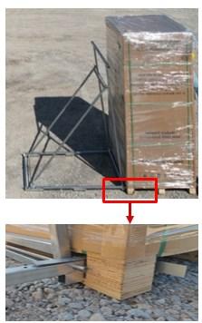
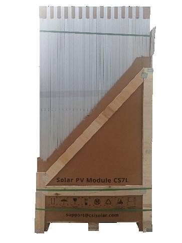

Unpackinginstructionsof palletwithunpacking bracket (PDF)

Assemblyinstructionsof theunpackingbracket (Video)

Unpackinginstructionsof palletwithunpacking bracket(Video)

Unpackinginstructionsof palletwithwoodenbeams (Video)
During unpacking, the unpacked modules should be properly fixed. After unpacking, it is recommended to place the remaining uninstalled modules horizontally onapallet.Stackingofmodulesshouldbelimitedtono more than 12 modules and frames should be aligned
with one another on the pile. Visit our website or contact your Canadian Solar representative for more detailedunpackingrequirements.
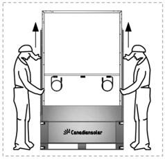
Do not lift modules by their wires or junction box, lift thembytheframe.
Donotallowthemodulestosagorbowduetoexternal forcesotherthangravitywhenbeingcarried.
Donotplaceexcessiveloadsonthemoduleortwistthe module.
Donotcarrymodulesonyourhead.
Do not drop or place objects (such as tools) on the modules.
Do not use sharp instruments on the modules. For single glass modules with polymer backsheets, particular care should be taken to avoid module backsheets being damaged by sharp objects, as scratchesmaydirectlyaffectproductsafety.
Donotleavemodulesunsupportedorunsecured.
Do not support the module by its backsheet or back glasswhencarryingormountingit.
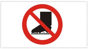
Do not stand, step, walk, and/or jump on modules under any circumstances. Localized heavy loads may causeseveremicro-cracksatthecelllevel,whichinturn may compromise module reliability and void Canadian Solar’swarranty.
Donotchangethewiringofthebypassdiodes.
Keepallelectricalcontactsalwayscleananddry
Donotexposethemodulesandtheirelectricalcontacts (junction boxes, connectors) to any unauthorized chemicalsubstance(e.g.oil,lubricant,pesticide,petrol, white flower oil, activating collaterals oil, mold temperature oil, machine oil (such as KV46), grease (such as Molykote EM-SOL, etc.), lubricating oil, antirust oil, stamping oil, butter , cooking oil, propyl alcohol, ethyl alcohol, essential oil, bone-setting water, Tianna water, mold release agent (such as Pelicoat S-6, etc.),glueandpottinggluethatcangenerateoximegas (suchasKE200,CX-200,Chemlok,etc.),TBP(plasticizer), cleaning agents, pesticide, paint strippers, adhesives, antirustagent,disincrustant,emulsifyingagent,cutting oilsandcosmetics,etc.)asmodulesmayincurdamages. Please contact your Canadian Solar representative for moredetailedrequirements.
Each module has identical barcodes (one in the laminate under the front glass, the other one on the frame) containing aunique14 or16-digit serialnumberthat act asauniqueidentifier.
A nameplate is also affixed to the rear of each module. This nameplate specifies the model type, as well as the mainelectricalandsafetycharacteristicsofthemodule.It alsoincludesthebarcodewiththemodule’suniqueserial numberasmentionedabove.

PRECAUTIONARYMEASURESANDGENERAL SAFETY
Priortoinstalling modules,pleaseobtain information about any requirements and necessary approvalsforthesite,installation,and inspectionfrom
therelevantauthorities.
Check applicable building codes to ensure that the construction or structure (roof, facade, support, etc.) canbearthemodulesystemload.
Canadian solar modules have been qualified for Application Class A (equivalent to Safety Class II requirements). Modules rated under this class should be used in systems operating at voltage above 50V or power above 240W, where general contact access is anticipated.
Canadian Solar double glass modules have been certifiedasType29accordingtoUL61730andasClass CaccordingtoIEC61730-2forfireperformance Single glassmonofacialmoduleshavebeencertifiedasType1 orType2 according toUL61730 and ClassCaccording to IEC 61730-2. Please refer to the datasheet or the productnameplateforthedetailedtypes
Consult your local authority for guidelines and requirementsforbuildingorstructuralfiresafety.
The fire rating of this module is only valid when the product is installed as specified in the mechanical mountinginstructions.
When installing the modules, ensure the assembly is mounted over a fire-resistant roof covering rated for theapplication.
Photovoltaic systems composed of UL 61730 certified modules mounted on a UL 2703 certified mounting system should be evaluated in combination with roof coverings in accordance with UL 61730 standard, with respect to meeting the same fire classification as the roofassembly.
Mounting systems with a System Fire Class Rating, tested in conjunction with ‘type 1’, ‘type 2’ or ‘type 29’ fire-ratedmodules,areconsideredacceptableforusing with Canadian Solar modules, providing the mounting systemdoesnotviolateanyotherrequirementsofthis manual.
Any mounting system limitations on inclination or accessories required to maintain a specific System Fire Class Rating should be clearly specified in the
installationinstructionsandUL2703certificationofthe mountingsystemsupplier.
PV modules are intended for use in general open-air climates, as defined in IEC 60721-2-1: Classification of environmental conditions Part 2-1: Environmental conditions appearing in nature-Temperature and humidity.
It is recommended that PV modules be installed in an environmentwithambienttemperaturerangingfrom40 °C to +40 °C. The 98th-percentile of the module operational temperature should be of 70 °C or lower under any mounting conditions If the application where the 98th-percentile of the module operational temperature of 80 °C is needed, please request IEC 63126Level1moduletypes.
This environmental temperature range encompasses many locations and installation methods. Annex A provides the reader with modeled PV module temperature examples, at the 98th-percentile dependingonthedifferentworldwidelocations.
Please consult the Canadian Solar technical support department for more information on the use of modulesinspecialclimates,suchasanaltitudegreater than 2000 m, heavy snow, severe hailstorm, hurricane, etc
Donot installmodulesnearopenflamesorflammable materials.
Donotimmersemodulesinwaterorconstantlyexpose modules to water (either fresh or salt, e.g. from fountains,seaspray).
Exposing modulestosalt(i.e.marineenvironments) or sulfur (i.e. sulfur sources, volcanoes) incurs the risk of modulecorrosion.
Do not expose modules and their connectors to any unauthorized chemical substances (e.g. oil, lubricant, pesticide,etc.),asmodulesmayincurdamages.
Canadian solar modules have passed the salt mist corrosion resistance test according to IEC 61701, but thecorrosionmaystilloccurwherethemodulesframe
is connected to the bracket or where the grounding is connected.Should theinstallationlocationbenearthe ocean, Canadian solar recommends stainless steel or aluminum materials be used in the areas with direct contactwiththePVmodules,andtheconnectionpoint should be protected with anti-corrosion measures. For more information, please contact Canadian solar technicalsupportteam.
Ensure that the module meets the general technical systemrequirements.
Ensurethatothersystemscomponentsdonotdamage themodulemechanicallyorelectrically.
Modulescanbewiredinseriestoincreasevoltageorin parallel to increase current. To connect modules in series,connectthecablesfromthepositiveterminalof one module tothenegativeterminalofthenextmodule. To connect in parallel, connect the cables from the positiveterminalofonemoduletothepositiveterminal ofthenextmodule.
The quantity of bypass diodes in the module junction boxprovidedmayvarydependingonthemodelseries.
Onlyconnectthequantityofmodulesthatcorresponds tothevoltagespecificationsoftheinvertersusedinthe system. In addition, modules must not be connected togethertocreateavoltagehigherthan themaximum permitted system voltage stated on the module nameplate, even under the worst local temperature conditions (see Table 1 for the correction coefficients thatapplytoopen-circuitvoltage).
Amaximumoftwostringscanbeconnectedinparallel without using anover-currentprotectiondevice(fuses, etc.)incorporated inserieswithin eachstring.Threeor more strings can be connected in parallel if an appropriate and certified over-current protection device is installed in series within each string. And it shall be ensured in the PV system design that the reversecurrentofanyparticularstringislowerthanthe modulemaximumfuseratingunderanycircumstances.
Onlymoduleswithsimilarelectricalparametersshould be connected in the same string to avoid or minimize
mismatcheffectsinarrays.
To minimize risk in the event of an indirect lightning strike, avoid forming loops with the wiring when designingthesystem.
Modules should be safely fixed to bear all expected loads,includingwindandsnowloads.
A minimum clearance of 6.5 mm (0.25 in) between modules is required to allow thermal expansion of the framesandmodules.
Thedrainholesshouldnotbeblocked.
OPTIMUMORIENTATIONANDTILT
To maximize the annual yield, please calculate the optimum orientation and tilt for PV modules in that specificinstallationsite.Thehighestyieldsareachieved when sunlight shines perpendicularly onto the PV modules
AVOIDSHADING
Modules shall not be permanently shaded (including partial shading, spot shading, even shading or uneven shading)underanycircumstances.Permanentshading means cells are continuously shaded for extended periods of time, such as installing modules behind a pipeorachimney,etc.Ifadefect(suchasahotspot)is causedduetoapanelbeingimproperlyinstalledinthe shadeorduetopoormaintenance,itwillvoidCanadian Solar’s warranty. Power dissipated in fully or partially shadedcellswillresultinpowerloss,reducedyieldand can cause localized overheating, which in turn may negatively impact the module service lifetime. Permanent shading may cause accelerated ageing of theencapsulationmaterialandplacethermalstresson the bypass diodes. This would void the module’s warranty unless properly mitigated through the use of ModuleLevelPowerElectronic(MLPE)devices.
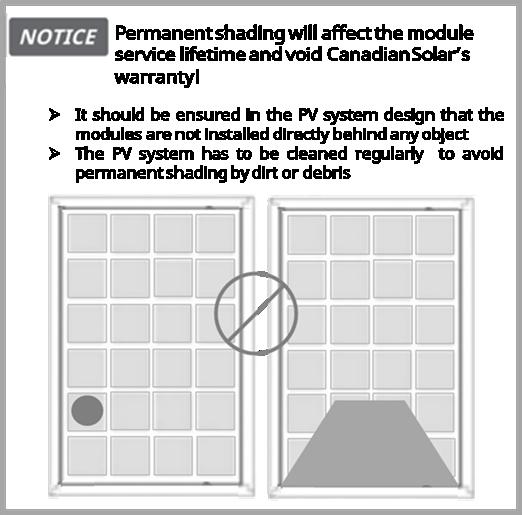
Regularmaintenanceisrequiredtokeepmodulesclean. Particular measures should be taken to avoid permanentshadingfromdirtordebris(e.g.,plants,bird droppings,etc.).
Do not install modules directly behind any object (e.g., tree,antenna,etc.)topreventoccurrenceofpermanent shading.
Even temporary partial shading will reduce the energy yield. A module can be classified as unshaded if its entire surface is free from shading all year round, includingontheshortestdayoftheyear.

Foroptimizingthepowergenerationoftherearsideof bifacial modules, obstacles between modules and the mounting ground should be avoided as much as possible.
RELIABLEVENTILATION
Bifacial modules use direct, reflected, or diffuse
sunlight on the backside to generate additional power. Therefore, bifacial modules are not suggested to be usedinbuildingattachedphotovoltaicsystems(BAPV).
Sufficientclearanceofat least10 2cm(4.0in)between themodulebottomsideandthesurfaceofrooforwall needs to be provided to allow cooling air to circulate around the back of the module. This also allows condensationormoisturetodissipate.Inparticular,the minimum clearance of any modules applied in BWh area (please refer to Annex A Figure A.2) should be determinedbyCanadianSolar’stechnicalserviceteam.
According to UL 61730, any other specific clearance required for maintaining a system fire rating should prevail. Detailed clearance requirements pertaining to system fire ratings must be provided by your racking supplier.
Cable management scheme should be reviewed and approvedbytheEPCcontractor.Requiredcablelengths should be cross-checked and account for tracker structure particularities e.g. bearing house gaps. If longercablesoradditionaljumpercablesarerequired, please contact Canadian Solar’s sales representative in advance.
Ifthecablesaresecuredonthebacksideofthemodule by locating tapes. Please remove it from the module during installation. It is recommended to remove glue remainingonthesurface,ifthereareany.
Ensurethat thewiring iscorrectbeforestarting up the system. If the measured open circuit voltage (Voc) and short-circuit current (Isc) differ from the specifications,
thisindicatesthatthereisawiringfault.
Whenmoduleshavebeeninstalled,butthesystemhas not been connected to the grid yet, each module and each string should be kept under open-circuit conditionsandproperactionsshouldbetakentoavoid dustandmoisturepenetrationinsidetheconnectors.In particular, short-circuiting the connectors of modules usingHJTcellsisnotpermittedpriortooperationofthe system.
Fordoubleglassmodules,CanadianSolaroffersseveral cable length options to match various system configurations,incaseajumpercableisneeded,please contactyourCanadianSolarsalesrepresentative.
The cable lengths assume the purlin connecting the modules to be no more than 80 mm protruding from the back side of the module and the distance between twomodulestobenomorethan25mm Verifyproper wiremanagementwithmountingsuppliershouldyour configurationdiffer
If the total length of the cable > 700 mm, it is recommendedtosecurethecablesusingcableclipsor zip ties. Due to the operation of tracker or any other environmental forces, the secured cables may loosen. Pleaseregularlyinspectthecablefasteningstoprevent the connectors from hanging due to cable loosening. Lengths of standard cables are relatively short, so it is advisabletoassesstheneedforcablefixationbasedon the project’s specific requirements or to consult CanadianSolar’stechnicalserviceteam.
For different module types, recommended system cableschemesareshownintable2below.Onthebelow figures,boldlinesrepresentcableinstallationpathways, while + and - connector correspond to positive and negativemoduleterminalsrespectively.
Table2:SystemCableSchemeforCS6L,CS6W,CS6R,CS6RA,CS7NandCS7Lmodules
Moduletypes Recommendedwiringconfigurations
Landscapeinstallationtworows:
CS6L-MS
CS6R-MS
CS6R-MS-HL
CS6R-MB-HL
CS6W-MS
CS7N-MS
CS7L-MS
CS6W-T
CS6R-T
CS6R-H-AG
CS6W-MB-AG
CS6W-TB-AG
CS6.1-54TB
CS6.1-54TM-H
CS6.1-60TB
CS6.1-60TM
CS6.1-60TM-H
CS6.1-72TB
CS6.1-72TB-H
CS6.1-54TD
CS6.1-72TD
CS6.2-32TM
CS6.2-36TM
CS6.2-48TD
CS6.2-48TM
CS6.2-54TM
CS6.2-66TB
CS7-60HB
CS7-66HB
CS7N-MB-AG
CS7L-MB-AG
CS7N-TB-AG
CS7L-TB-AG

Note:Adjacentmodulesinthesamerowneedtoberotated180degreesforproper installation.
Portraitinstallationonerow:

Portraitinstallationtworows:

Note:Modulesinadjacentrowsneedtoberotated180degreesforproperinstallation.
PortraitinstallationonerowLeap-frog(forsingle-axistracker):
CS6W-MB-AG
CS6W-TB-AG
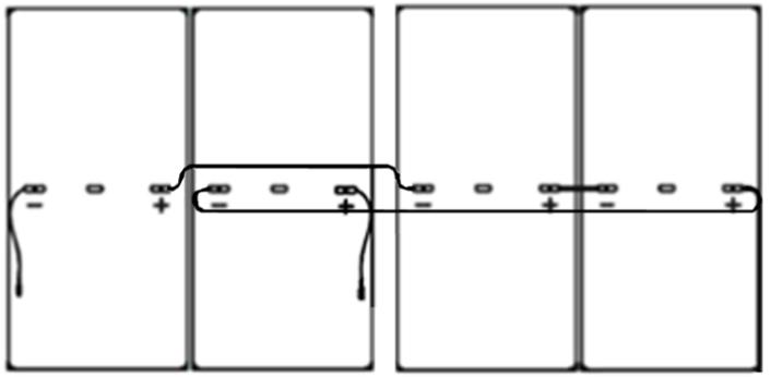
Themaximumdistancebetweentwoadjacentmoduleframesshouldbewithin50mm(1.96in)forthesidewithmounting clamps,andwithin25mm(0.98in)forthesidewithoutmountingclamps,inordertomeetthesystemcablescheme.
Make sure that all connections are safe and properly mated ThePVconnectorshouldnotbesubjecttostress from the exterior. Connectors should only be used to connect the circuit. They should never be used to turn thecircuitonandoff.
Donotpinchthepositiveconnectorwings.

Connectors are not waterproof when unmated. When installing modules,connectorsshould beconnected to eachotherassoonaspossibleorappropriatemeasures (likeusingconnectorendcaps)shouldbetakentoavoid moistureanddustpenetratingintotheconnector.
The connectors in normal working conditions have passed tests for water drainage, dust prevention, and ultraviolet radiation.Tofurtherprotecttheconnectors, ifnecessary,itisrecommendedtoavoiddirectsunlight or rain exposure and stay away from areas prone to wateraccumulation.
If end caps are present on un-mated connectors, carefully remove by hand the end caps before connecting the connectors. Do not use any sharp tool which may damage the connector. The use of tools is notneeded.

Donotconnectdifferentconnectors(brandandmodel)
Do not clean or precondition the connectors using lubricantsoranyunauthorizedchemicalsubstances.
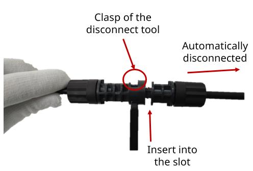
The mated connectors can only be disconnected by special disconnecting tools. Insert the clasp of the
disconnecting tool in the slots of the male connector, and the female connector will automatically get disconnected.
Onlyusededicatedsolarcableandsuitableconnectors (wiring should be sheathed in a sunlight-resistant conduitor,ifexposed,shoulditselfbesunlight-resistant) that meet localfire,building and electrical regulations Please ensure that all wiring is in perfect electrical and mechanicalcondition.
Installers may only use single-conductor cable listed andlabeledasPVwirewhichis90°CwetratedinNorth America, and single conductor cable with a cross sectionareaofatleast4mm²(12AWG),90°Cwetrated in other areas (i.e. IEC 62930: 2017 approved), with proper insulation which is able to withstand the maximumpossiblesystemopen-circuitvoltage.
Onlycopperconductormaterialshouldbeused.Select a suitable conductor gauge to minimize voltage drop and ensurethat theconductorampacitycomplieswith localregulations(e.g.NEC690.8(D)).
Secure the cables to the mounting system using UVresistant cable ties. Protect exposed cables from damagebytakingappropriateprecautions(e.g.placing theminsideametallicracewaylikeEMTconduit).Avoid exposuretodirectsunlight.
A minimum bending radius of 60 mm (2.36 in) is required when securing the junction box cables to the racking system. For a smaller bending radius, it is recommendedtorefertoIEC62440.
Protect exposed connectors from weathering damage
by taking appropriate precautions. Avoid exposure to directsunlight.
Donotplaceconnectorsinlocationswherewatercould easilyaccumulate.
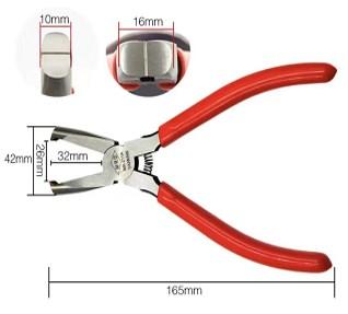
Canadian Solar uses ribbons to fix cables. End cutting pliers or a similar tool is recommended for cutting the ribbonstoavoidanydamagetocables.
Endcuttingpliersimage
Forgroundingrequirements,althoughthemodulesare certified to Safety Class II, we recommend them to be grounded and that module installation should comply withallapplicablelocalelectricalcodesandregulations. Minimum size of equipment grounding conductors for ground raceway and equipment from NEC 690.8(D) should be considered. Grounding connections should be installed by a qualified electrician. Connect module frames together using adequate grounding cables: we
recommend using 4-14 mm² (AWG 6-12) copper wire. Holes provided for this purpose are identified with a grounding symbol (IEC 61730-1). All conductive connectionjunctionsmustbefirmlyfixed.
For grounding requirements in North America, a modulewithexposedconductivepartsisconsideredto comply with UL 61730 only when it is electrically grounded in accordance with both the instructions presented belowand therequirementsofthe National Electrical Code. Any grounding means used with CanadianSolarmodulesshouldbeNRTLcertifiedtoUL 467 and UL 2703 standards. Please consult our technicalserviceteamfortheformalapprovalprocess.
Do not drill any extra ground holes for convenience as thiswillvoidthemodule’swarranty.
All bolts, nuts, flat washers, lock washers and other relevant hardware should be made of stainless steel, unlessotherwisespecified.
CanadianSolardoesnotprovidegroundinghardware.
Canadian Solar material selection substantially limits potentialinduceddegradation(PID).ShouldfurtherPID suppression be desired for the project, negative grounding is still an optional measure for PID mitigation and for optimal performance Anti-PID function of inverters is another option. Please consult yourinvertersuppliersformoreinformation.
The grounding method described below is recommendedforCanadianSolar
GROUNDINGMETHOD:BOLT+TOOTHEDNUT+CUPWASHER.
To fix the wire between the flatwasherandcupwasher, place the cup washer (concave side up) between theframeandthewire. Then tighten the bolt usingthetoothednut.
AgroundingkitcontaininganM5(3/16")SScapbolt,an M5 (3/16") SS flat washer, an M5 (3/16") SS cup washer, and an M5 (3/16") SS nut (with teeth) is used to attach copper grounding wire to a pre-drilled grounding hole ontheframe(seeimageabove).
Place the wire between the flat washer and the cup washer. Ensure that the cup washer is positioned
between the frame and the wire with the concave side up to prevent galvanic corrosion. Tighten the bolt securely using the SS toothed nut. A wrench may be usedtodothis.Thetighteningtorqueis3-7Nm(2.2-5.2 ft-lbs).
For bifacial modules, mounting rail designs should be such to allow easy access to the grounding holes locatedonthelongsideoftheframe,inordertoenable theequipmentgroundingfunctionwhenrequired.

Theapplicableregulationspertainingtowork safety, accident prevention and securing the construction site must be observed. Workers and third-party personnel shall wear or install fall arrest equipment. Any third party need to be protected against injuriesanddamages.
The mounting design must becertified by a registered professional engineer. The mounting design and proceduresmustcomplywithallapplicablelocalcodes andrequirementsfromallrelevantauthorities
The module is considered to be in compliance with UL 61730 and IEC 61215/61730 only when the module is mounted in the manner specified by the mounting instructions included in this installation manual or whenspeciallyapprovedbyCanadianSolarinwriting
The system designer and installer are responsible for load calculations and for proper design of support structure.
Themechanicalload testsinthismanualareonlyvalid whencoupledtomountingandsupportstructuresthat are capable of withstanding equal or greater mechanical loads. The mounting system supplier is responsible for the strength and stability of the mounting structure, which must meet the requirementsoftherelevantdesignspecifications.
The loads described in this manual correspond to test loads. For installations complying with UL 61730 and IEC 61215/61730, a safety factor of 1.5 should be applied for calculating the equivalent maximum authorized design loads. Project design loads depend on construction, applicable standards, location and
local climate. Determination of the design loads is the responsibility of the racking suppliers and/or professional engineers. For detailed information, please follow local structural code or contact your professionalstructuralengineer.
Itisknownthatloaddistributiononthemoduleareais not balanced. Wind and snow loads are unevenly distributed onthemodule’s surface,and such must be considered in the definition of the PV module design load and the respective restrictions to apply for the mountingsupportsystem.Thetestloadvalueshownin this manual is the uniform load. The maximum allowable unbalanced design load (Pmax) must be lowerthan0.8(unbalancedfactor)×Testload.

During installation, it is necessary to inspect the componentsbelowthemoduletoensurethatthereare no zinc slag protrusions or burrs on the surface, in ordertoavoiddamagetotheglassorbacksheet.
Useatorquewrenchforinstallation.
Do not drill additional holes or modify the module frame.Doingsowillvoidthemodule’swarranty.
This manual includes preliminary loading capability data which might be subject to change in the coming versions. Please check for the latest version of this manual.
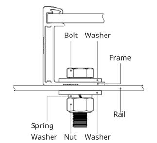
Use appropriate corrosion-proof fastening materials. All mounting hardware (bolts, spring washers, flat washers,nuts)shouldbehotdipgalvanizedorstainless steel.
Installandtightenthemoduleclampstothemounting
railsusingthetorquestatedbythemountinghardware manufacturer. Recommended accessories are shown below.
Bolt
Washer
Notethat:
M8x1.25-Grade8.8 (5/16”-18GradeB7) galvanizedorA2-70 stainlesssteel coarsethreadbolts. M6X1(1/4”) coarsethread bolts
2pcs,thickness ≥1.5mmand outsidediameters= 16mm
2pcs,thickness ≥1.5mmand outside diameters=1216mm
Bolt locations on the module, where M6 bolts are used onlyinsingle-axistracker
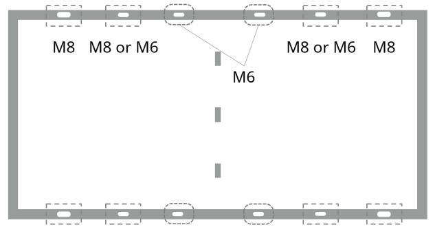
1) M8 and M6 bolt tightening torques must be within 16~20 Nm(11.8~14.75 ft-lbs)and 6~9 Nm(4.5~6.6 ft-lbs), respectively,dependingonboltclasses Fortheboltgrade, the technical guidelines from the fastener suppliers should be followed. Different recommendations from specificclampinghardwaresuppliersshouldprevail.
2)Theyieldstrengthoftheboltandnutshouldnotbeless than450MPa.
3) When using serrated bolts and/or serrated nuts, it is not necessary to attach spring washers, but in order to ensurethestabilityoftheconnection,werecommendthe use of nuts with anti-loosening function for installation During tracker installation, ensure that the outer diameter of the M6 serrated bolt falls between 16~16.8 mm. If not, insert a 16 mm outer diameter washer betweenthemoduleandthebolt Fastenersmuststrictly follow the relevant standards to ensure that the quality and performance. The grounding connectivity check of theserratedboltstogetherwiththemoduleframeis out of the scope of this manual and is sole responsibility of the racking supplier and installer, following local regulations.
The laminate of the PV modules will sink downward to varying degrees due to gravity, with the center of module being the maximum deflection position. While using bolting or clamping mounting method or insertion system, the maximum allowable deflection (ΔL shown in the picture below) is 20 mm (in the absenceofexternalforcescausedby,forexample,wind and snow). Note that applying pressure to the module surface during storage, transportation and installation willleadtomoreseveredeflection.

Themechanicalloadtestwiththesemountingmethods wereperformedaccordingtoIEC61215.
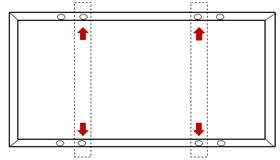
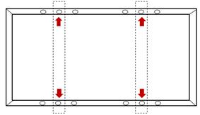
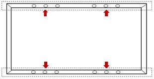
Modules should be bolted to supporting structures through the mounting holes in the rear frame flanges only.
Each module must be securely fastened at a minimum of4pointsontwooppositesides
Suitable bolt length should be chosen based on actual module frame height. For double glass module with 30 mm frameheight,ourrecommendedmaximumboltlength is 20 mm in order to properly insert the bolts through themountinghole.Thesystemdesigneris responsible to check that the racking supplier specified bolt length complies with above requirement and will not affect installation.
In areas with heavy wind loads, additional mounting points should be used. The system designer and the installer are responsible for correctly calculating the loadsandensuringthatthesupportingstructuremeets alltheapplicablerequirements.
Mountingmethod:Bolting
Modules should be bolted at the following hole locations depending on the configuration and loads, whichisshownintable3.
Table3:Approvedboltingmethods



InstallationMethod ModuleTypes
CS6L-MS
CS6R-MS/CS6RA-MS/ CS6RB-MS
CS6R-MS-HL*
+5400Pa/ -2400Pa / / / / /
CS6R-MB-HL* +5400Pa/ -4000Pa +5400Pa/ -4000Pa / / / /
CS6W-MS/CS6W-MB-AG
CS7L-MS(F53A2 &F563 Frame)
CS7N-MS(F53A2 &F563 Frame)
CS6W-T/CS6W-TB-AG / / / / +5400Pa/ -2400Pa /
CS6W-T(F726 Frame) / / / / +5400Pa/ -2400Pa /
CS6R-T +5400Pa/ -2400Pa +4000Pa/ -2400Pa / / / /
CS6.1-54TB*(F451 Frame)
CS6.1-54TD*(F451 Frame) / / / / +5400Pa/ -2400Pa +3600Pa/ -2400Pa
CS6.1-54TB*(F732 Frame)
CS6.1-54TD*(F732 Frame) +6000Pa/ -4000Pa +3600Pa/ -2400Pa
CS6.1-54TM-H* / / / / +5400Pa/ -4000Pa +5400Pa/ -4000Pa
CS6.1-60TM / / / / +5400Pa/ -2400Pa /
CS6.1-60TM-H* / / / / +5400Pa/ -3700Pa +5400Pa/ -4000Pa
InstallationMethod ModuleTypes
CS6.1-60TB / / / / +5400Pa/ -2400Pa +4000Pa/ -2400Pa
CS6.1-72TB/CS6.1-72TD / / / / +5400Pa/ -2400Pa +4000Pa/ -2400Pa
CS6.1-72TB/CS6.1-72TD (F716 Frame) / / / / +5400Pa/ -2400Pa +4000Pa/ -2400Pa
CS6.1-72TB-H* / / / / +5400Pa/ -4000Pa +5400Pa/ -4000Pa
CS6.2-32TM
CS6.2-36TM
CS6.2-48TM +5400Pa/ -2400Pa / / / / /
CS6.2-48TD / / / / +5400Pa/ -2400Pa /
CS6.2-54TM / / / / +5400Pa/ -2400Pa /
CS6.2-66TB(F671 &F716 Frame) / / / / +5400Pa/ -2400Pa +4000Pa/ -2400Pa
CS7-60HB/CS7-66HB / / / / +5400Pa/ -2400Pa +2800Pa/ -2400Pa
CS7N-MS(F632 Frame)
CS7L-MS(F632 Frame) / / / / +5400Pa/ -2400Pa +2400Pa/ -2400Pa
CS7N-MB-AG(F432 Frame)
CS7L-MB-AG(F432 Frame) / / / / +5400Pa/ -2400Pa +3600Pa/ -2400Pa
CS7N-MB-AG(F463 Frame)
CS7L-MB-AG(F463 Frame)
CS7N-TB-AG/CS7L-TB-AG / / / / +5400Pa/ -2400Pa +2800Pa/ -2400Pa
CS6R-H-AG/ +5400Pa/ -2400Pa +3600Pa/ -2400Pa / / / /
Note:Theinstallationmethodofboltisbasedontheexperimentalresults,“/”meansnottested.Loads inthetablearetestloads,pleaserefertosection6.*:D-typewasher(asshownontheright)withouter diameter23mmshouldbeused.
Formodulesthathaveonlyfourmountingholes,thoseholesarereferredtoas“outerfourholes”.
1:with30mmheightframe;
2:with35mmheightframe;
3:with33mmheightframe
6:anti-dustmodule.
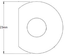
If there is only one set of mounting holes on the frame, it is regarded as the outer four holes. If there are two sets of holes,theyareregardedasouterfourholesandinnerfourholes.
For ease of reference, the designation ‘A/B’ included in frame model names has been consistently omitted across all tableswithinthismanual.
Themechanicalloadtestwiththesemountingmethods wereperformedaccordingtoIEC61215.
Clamping methods will vary and are dependent on the mounting structures. Please follow the mounting guidelines recommended by the mounting system supplier.
Each module must be securely fastened at a minimum offourpointsontwooppositesides.Theclampsshould be positioned symmetrically. The clamps should be positionedaccordingtotheauthorizedpositionranges defined in the tables below. Install and tighten the module clamps to the mounting rails using the torque statedbythemountinghardwaremanufacturer.
The system designer and the installer are responsible for load calculations and for proper design of support structure.
For bifacial modules, the mounting rails shall be designed to limit as much as possible the shade on modulerearsidecells.
Canadian Solar’s warranty may be voided in the cases whereimproperclamps(Forexample,theclampheight does not match with the frame height) or unsuitable installation methods are found. When installing intermodulesorend-typeclamps,pleasetakethefollowing measuresintoaccount:
1.Donotbendthemoduleframe.
2.Donottouchorcastshadowsonthefrontglass.
3.Do not damage the surface of the frame (to the exceptionoftheclampswithbondingpins).
4.Ensure the clamps overlap the module frame as specified in table 4. For configurations where the mounting railsrunparalleltotheframe,precautions should be taken to ensure the bottom flange of the moduleframeoverlapstherailasspecifiedintable4 aswell.
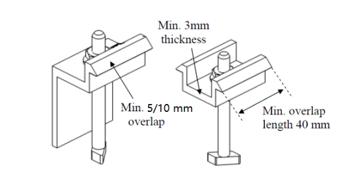

5.Ensuretheclampthicknessisatleast3mm(0.12in).
Clamp material should be anodized aluminum alloy or stainlesssteel.
Clamp positions are of crucial importance for the reliabilityoftheinstallation.Theclampcenterlinesmust only be positioned within the ranges indicated in the tablesbelow,dependingontheconfigurationandload.
Table4:Overlapdepthandlengthinclampmountingmethod
Overlapbetween
Moduleframeand clamp Depth
Moduleframe bottomflangeand mountingrail
10mm(0.4in)
5mm(0.2in)
15mm(0.59in)
10mm(0.4in)
15mm(0.59in)
CS6W,CS6.1-72TB,CS6.1-72TD,CS6.2-66TB, CS7LandCS7Ntypes
Othermoduletypes
Upliftload>2400Pa
Upliftload ≤ 2400Pa
CS6W,CS6.1-72TB,CS6.1-72TD,CS6.2-66TB, CS7L,andCS7Ntypes
Otherdoubleglassmodules
Allsingleglassmodules
6.2.1Clampmountingonlongsideofframeandrailsperpendiculartothelongsideframe

Module
CS6L-MS /
CS6R-MS
CS6RB-MS
CS6RA-MS
CS6R-MS-HL
CS6R-MB-HL
CS6W-MS(F35A1 Frame)/CS7L-MS /
CS6W-MS(F451 Frame)/CS6W-T
CS7N-MS(F53A2 &F563 Frame) /
CS6R-T
CS6W-T (F726 Frame)
CS6W-MB-AG (F47 1 &F47L 1 Frame)
CS6W-TB-AG (F471 &F47L1 Frame) /
CS6W-MB-AG (F42 2 Frame)
CS6W-TB-AG (F42 2 Frame) /
CS6.1-54TB
CS6.1-54TD
CS6.1-54TM-H
CS6.1-60TM / / / / / /
CS6.1-60TM-H
CS6.1-60TB
CS6.1-72TB
CS6.1-72TD
CS6.1-72TB
/ / / /
CS6.1-72TD (F716 Frame) / / / / / / 450550 / / / /
CS6.1-72TB-H
CS6.2-32TM
CS6.2-48TM / / / /
/ / / /
CS6.2-36TM / / / / / / 200400 / / / /
CS6.2-48TD 60600
CS6.2-54TM / / / / / / 400500 / / / /
CS6.2-66TB(F671 Frame) 60600 / / / 350600 / 450550 / / / /
CS6.2-66TB(F716 Frame) / / / / / / 450550 / / / /
CS6R-H-AG
CS7-60HB
CS7-66HB / / / / / / 450550 / / / /
CS7N-MS(F632 Frame) / / / / 300600 / 450550 4 / / / /
CS7L-MS(F632 Frame) / / / / 300600 / 400500 / / / /
CS7L-MB-AG
CS7L-TB-AG / / / / / / 400500 / / / /
CS7N-MB-AG
CS7N-TB-AG / / / / / / 450550 / / / /
1:with30mmheightframe;
2:with35mmheightframe;
3:with33mmheightframeandahookedclamp,whichisshownbelow
4:onlyiftheclamplengthwasextendedto60mmorifahookedclampwasused.PleaseconsultCanadianSolar’s technicalserviceifyouneedtouseclampswithdifferentsizes.
5:onlyiftheclamplengthwasextendedto60mm.
6:anti-dustmodule
*:testloads,pleaserefertosection6
♢:clampoverlaplengthshouldbeatleast80mm.
Hookedclampdiagram

6.2.2Clampmountingonshortsideofframeandrailsperpendiculartothelongsideframe.
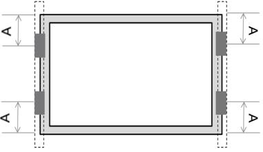
ModuleTypes
CS6L-MS/CS6W-MS (F451 Frame)/CS6W-T
CS6R-MS/CS6R-T
CS6RA-MS/CS6RA-T
CS6RB-MS/CS6RB-T
MechanicalLoad(Pa)*
CS6R-H-AG / / / +1800/-1800♢ /
CS6R-MS-HL/CS6R-MBHL / +2400/-2400 / / +2600/-2400
CS6W-MB-AG(F422 Frame) / +1000/-1000 / / /
CS6.1-54TB
CS6.1-54TD / / +1600/-1600 / /
CS6.1-54TM-H / / / / +2400/-2400
CS6.1-60TB / / / +1800/-1800 /
CS6.1-60TM / / / +1800/-1800 /
CS6.1-60TM-H / / / / +2000/-2000
CS6.1-72TB
CS6.1-72TD / / +800/-800 / /
CS6.1-72TB-H +1000/-1000 / / +1400/-1400 /
CS6.2-48TD / / / +1600/-1600 /
CS6.2-54TM / / / +1800/-1800♢ /
CS6.2-66TB / / +800/-800 / /
♢:clampoverlaplengthshouldbeatleast80mm;
1:with30mmheightframe;
2:with35mmheightframe; *:testloads,pleaserefertosection6
6.2.3Clampmountingonlongsideofframeandrailsparalleltothelongsideframe.

ModuleTypes
CS6L-MS / 100500 / / / 300500 / / / /
CS6R-MS/CS6RBMS / / / / 200600 / 200300 / / /
CS6RA-MS / / / / / / 200400 / / /
CS6R-MSHL/CS6R-MB-HL / / / / / /
/
CS6W-MS(F451 Frame)/CS6W-T 60-250 / / 400500 / / / / / /
CS6R-T / / / / 200600 / 200300 / / /
CS6W-MB-AG / / / / / / / 400500 / /
CS6W-T (F726 Frame) / / / / / / / 400500 / /
CS6W-TB-AG / / / / / / / 400500 / /
CS6.1-54TB
CS6.1-54TD / 100500 / / / 300500 / / / /
CS6.1-54TM-H
CS6.1-60TM-H / / / / / /
CS6.1-60TB 0-600 / 250600 / / / / 400500 / /
CS6.1-60TM / / / 350450 / / / / / /
CS6.1-72TB
CS6.1-72TD 100600 / 250600 / / / / 400500 / /
CS6.1-72TB
CS6.1-72TD / / / / / / / 400500 / /
/
ModuleTypes
(F716 Frame)
CS6.1-72TB-H
CS6.2-48TD
CS6.2-54TM
CS6.2-66TB(F671 Frame)
CS6.2-66TB(F716 Frame) /
CS7-60HB
CS7-66HB
CS7N-MB-AG (F432 frame)/
CS7L-MB-AG (F432 frame)/
CS6R-H-AG
CS7N-MB-AG (F463 frame)/
CS7L-MB-AG (F463 frame)
CS7N-TB-AG
CS7L-TB-AG
1:with30mmheightframe;
2:with35mmheightframe;
3:with33mmheightframe;
6:anti-dustmodule
*:testloads,pleaserefertosection6
A1Range
6.2.4Fourclampsonshortsideofframeandrailsparalleltothelongsideframe.
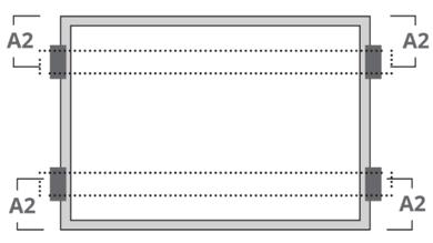
ModuleTypes
CS6R-MS/CS6R-T / +2200/-1800♢ +2400/-1800♢ /
CS6RA-MS/CS6RA-T
CS6RB-MS/CS6RB-T
CS6R-H-AG
CS6R-MS-HL/CS6R-MB-HL +2400/-2400 / / +5400/-2400
CS6.1-54TM-H +2400/-2400 / +5400/-2400 /
CS6.1-60TM-H +2000/-2000 / +5400/-2000 /
♢:clampoverlaplengthshouldbeatleast80mm;
*:testloads,pleaserefertosection6
6.2.5Sixclampsonlongsideofframeandrailsperpendiculartothelongsideframe

ModuleTypes
A3&A5Range(mm)
CS6R-MS/CS6RAMS/CS6RB-MS/ CS6R-T/CS6R-HAG / / / 80-380 / / /
CS6R-MS-HL
CS6R-MB-HL
CS6.1-54TM-H
CS6.1-60TM-H / 100-600 / / 300-550 / 350-450
CS6W-MB-AG (F471 &F47L1 frame)
CS6W-TB-AG / / / 300-500 / / /
CS6W-MB-AG (F422 frame) / / 350-450 / / / /
CS6.1-54TB
CS6.1-54TD / / / 300-400 / / /
CS6.1-60TB / / / / 300-500 / /
CS6.1-72TB
CS6.1-72TD / / / / 300-500 / /
CS6.1-72TB
CS6.1-72TD (F716 Frame) / / / / 300-500 / /
CS6.1-72TB-H 300-600 / / / / 300-400 /
CS6.2-48TD / / / 300-400 / / /
CS6.2-66TB / / / / 300-500 / /
1:30mmheightframe;
2:with35mmheightframe;
6:anti-dustmodule
*:testloads,pleaserefertosection6
6.2.6Twoclampsonthelongsideandtwoclampsontheshortsideofframe.Rails runperpendiculartothelongside frame.

ModuleTypes
CS6R-MS/CS6R-T
CS6R-H-AG
CS6.1-54TM-H / / / / / /
CS6RA-MS / / / / / /
CS6RB-MS / / / / / /
CS6R-MS-HL
CS6R-MB-HL / / / / / /
CS6W-MS(F451 Frame)/CS6W-T / / 600-800 200-250 / / / /
CS6W-MB-AG / / / / 600-700 200-250 / /
CS6.1-54TB
CS6.1-54TD / / / / / / 500-600 200-250
CS6.1-60TM-H 400-600 200-250 / / / / / /
CS6.1-60TB / / / / 600-700 200-250 / /
CS6.1-72TB
CS6.1-72TD / / / / 600-700 200-250 / /
CS6.1-72TB-H / / / / / / 600-700 200-250
CS6.2-48TD / / / / 500-600 200-250 / /
CS6.2-66TB / / / / 600-700 200-250 / / 1:with30mmheightframe; *:testloads,pleaserefertosection6
6.2.7Fourclampsmountingontheshortsideofframe.
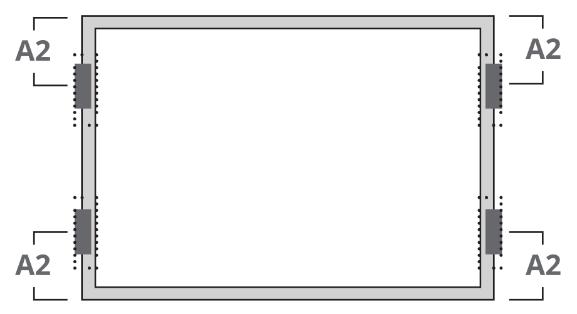
ModuleTypes
CS6L-MS
CS6R-MS/CS6R-T
CS6RA-MS/ CS6RA-T
CS6RB-MS/ CS6RB-T
Range(mm)
CS6R-H-AG / / 60-250♢ / / /
CS6R-MS-HL
CS6R-MB-HL / / / / 0-200 200-250
CS6.1-54TB
CS6.1-54TD / 0-250 / / / /
CS6.1-54TM-H / / / / / 200-250
CS6.1-60TM-H / / / 200-250 / /
CS6.1-60TB / / 60-250 / / /
CS6.1-72TB
CS6.1-72TD 0-250 / / / / /
CS6.2-48TD / 60-250 / / / /
CS6.2-66TB 0-250 / / / / /
♢:clampoverlaplengthshouldbeatleast80mm; *:testloads,pleaserefertosection6
6.2.8Fourclampsmountingonshortsideofframe,andanadditionalsupportbarplacedbelowthecenterofthe module.
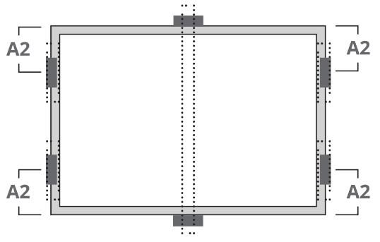
ModuleTypes
CS6R-MS/CS6RA-MS
A2Range(mm)
CS6RB-MS/CS6R-T / / 0-200 / /
CS6R-MS-HL
CS6R-MB-HL / / / 0-200 /
CS6R-H-AG / / / / 200-250
CS6.1-54TB
CS6.1-54TD 0-250 / / / /
CS6.1-60TB 0-250 / / / /
CS6.1-72TB
CS6.1-72TD 0-250 / / / /
CS6.1-72TB-H / 0-250 / / /
CS6.2-48TD 0-250 / / /
CS6.2-66TB 0-250 / / / / *:testloads,pleaserefertosection6
The following methods are recommended only for single glass monofacial modules. Note that clamp overlap length of 40mm(or1.50in)whenupliftload>2400Paisallowed.
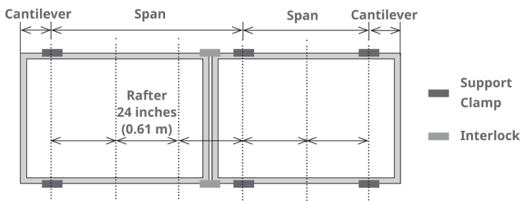
Landscapeinstallation,clampingonlongsideframe ModyleType
CS6R-MS-HL
CS6R-MB-HL
CS6.1-54TM-H
CS6.1-60TM-H
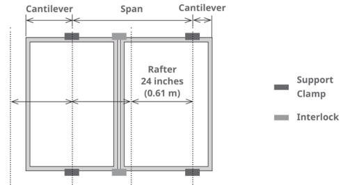
Portraitinstallation,clampingonshortsideframe
CS6R-MS-HL/CS6R-MB-HL
CS6.1-54TM-H
CS6.1-60TM-H
*:testloads,pleaserefertosection6
InsertionMethodCshownbelowisrecommendedonly formonofacialmodules.
Themechanicalloadtestwiththesemountingmethods wereperformedaccordingtoIEC61215.
Insertion methods can vary and depend on the mounting structures. The installer needs to follow the mounting guidelines recommended by the mounting system supplier. Each module must be securely maintainedthroughallitslengthontwooppositesides. Installand tightentheinsertionprofilestothesupport structureusingthehardwareandinstructionsprovided by the mounting system manufacturer. The system designer and installer are solely responsible for load calculations and for the proper design of support structure.
When installing insertion profiles, please take the followingmeasuresintoaccount:
1. Donotbendthemoduleframe.
2. Donottouchthefrontglassorcastshadowsontoit.
3. Donotdamagethesurfaceoftheframe.
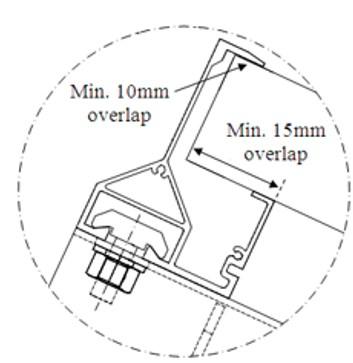
4. Ensurethattheinsertionprofilesoverlapthemodule framebyatleast10mm(0.39in).
5. Ensurethatthemoduleframe(C-shape)overlapsthe insertionprofilesbyatleast15mm(0.59in).
6. Ensureinsertionprofilethicknessandtolerancessuit modulethickness.
Canadian Solar warranty may be void in cases where improper insertion systems or unsuitable installation
InsertionMethodA

Twoinsertionprofilesrunparallelto longsideframe.
methods are used. The insertion profile thickness is recommended to be no more than the module thicknessplus1mm.
InsertionMethodB
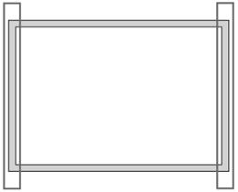
Twoinsertionprofilesrun perpendicularlytolongsideframe.
InsertionMethodC

An additional support bar used with clamps
CS6L-MS
CS6R-H-AG +3600Pa/-2400Pa +1800Pa/-1800Pa /
CS6R-MS/CS6R-T
CS6RA-MS/CS6RA-T
CS6RB-MS/CS6RB-T +4000Pa/-2400Pa +1800Pa/-1800Pa /
CS6R-MS-HL/CS6R-MB-HL +5400Pa/-2400Pa +2400Pa/-2400Pa +5400Pa/-2400Pa
CS6W-MS(F35A1 Frame) +4000Pa/-2400Pa +1800Pa/-1800Pa +5400Pa/-2400Pa
CS6W-MS(F451 Frame)
CS6W-T +3600Pa/-2400Pa +1800Pa/-1800Pa +5400Pa/-2400Pa
CS6W-MB-AG(F471 &F47L1 Frame) +3600Pa/-2400Pa* / /
CS6.1-54TB(F451 Frame)
CS6.1-54TD(F451 Frame) +3600Pa/-2400Pa +1600Pa/-1600Pa +3600Pa/-2400Pa
CS6.1-54TB(F732 Frame)
CS6.1-54TD(F732 Frame) +3600Pa/-2400Pa +2400Pa/-2400Pa +3600Pa/-2400Pa
CS6.1-60TB +3600Pa/-2400Pa +1800Pa/-1800Pa +3600Pa/-2400Pa
CS6.1-72TB/CS6.1-72TD +3600Pa/-2400Pa +800Pa/-800Pa +3600Pa/-2400Pa
CS6.2-48TD +3600Pa/-2400Pa +1600Pa/-1600Pa +3600Pa/-2400Pa
CS6.2-66TB +3600Pa/-2400Pa +800Pa/-800Pa +3600Pa/-2400Pa
1:with30mmheightframe;
2:with35mmheightframe
Theloadsinthetablearetestloads,pleaserefertosection6
*:JustforCWF0%overhang-insertionprofilecompletelywrapstheframewithoutcantilever.Raildistancemustbe ≥ 50% framefromtheshortendofonesideofthemodule
The following mounting methods are only recommendedfordoubleglassmodules.
Theboltsandclampsusedinthissectionshouldfollow therequirementsdescribedinchapter6.0.
Underanyconditionsthejunctionboxshouldnotcome in contact with the subjacent racking structure except for the torque tube under high loading For any single axis tracker installation configured with one module in portraitrows,bearing housescannot belocated under themodulejunctionboxes.
Installandtightenthemoduleclampstothemounting railsusingthetorquestatedbythemountinghardware manufacturer. M6 × 1 (1/4”) or M8 × 1.25 (5/16”) bolt andnutareusedforthisboltingmethod.
If any racking structures, especially bearing house, must be located under the modules, any racking structureshallnotbehigherthanframeCside.
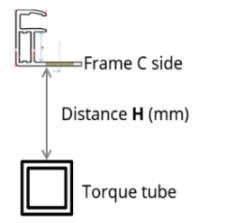
If your tracker design cannot meet the above distance requirement, please contact Canadian Solar technical supportdepartmentinwritingforadvice.
Thetighteningtorquesshouldbe6~9Nm(4.5~6.6ft-lbs) M6 × 1 (1/4”) coarse thread bolts for 10 × 7 mounting hole,dependingonboltclass.M8×1.25(5/16”)for14× 9mountinghole. Figures

CS6W-MB-AG(F422 frame)
CS6W-MB-AG(F471 & F47L1 frame)
A1-A3:400
B1-B3:790
C1-C3:1400
A1-A3:400 B1-B3:790
C1-C3:1400
A1,A2,A3,A4 16 65±5 +2000/-1800 B1,B2,B3,B4 16 65±5 +2400/-2200
C1,C2,C3,C4 16 65±5 +2400/-2200
A1,A2,A3,A4 16 65±5 +2100/-2100
B1,B2,B3,B4 16 65±5 +2800/-2400
C1,C2,C3,C4 16 65±5 +2800/-2400
CS6W-TB-AG A1-A3:400 A1,A2,A3,A4 16 65±5 +2100/-2100
Figures Moduletype Mounting holespace (mm) Fixed mounting holelocation Plainwasher outer diameter (mm) DistanceH (mm)

CS6.1-72TB
CS6.1-72TD
CS6.1-72TB-H
CS6.2-66TB
B1-B3:790
C1-C3:1400
A1-A3:400
B1-B3:790
C1-C3:1400
A1-A3:400
B1-B3:790
C1-C3:1400
A1-A3:400
B1-B3:790
C1-C3:1400
CS7-60HB
A1-A3:400
B1-B3:790
C1-C3:1400
CS7-66HB
CS7L-TB-AG
A1-A3:400
B1-B3:790
CS7N-TB-AG
CS7L-MB-AG
1:with30mmheightframe;
2:with35mmheightframe
CS7N-MB-AG
B1,B2,B3,B4 16 65±5 +2800/-2400
C1,C2,C3,C4 16 65±5 +2800/-2400
A1,A2,A3,A4 16 65±5 +1800/-1800
B1,B2,B3,B4 16 65±5 +2800/-2400
C1,C2,C3,C4 16 65±5 +2800/-2400
A1,A2,A3,A4 16 65±5 +1900/-1900
B1,B2,B3,B4 16 65±5 +2800/-2400
C1,C2,C3,C4 16 65±5 +2800/-2400
A1,A2,A3,A4 16 65±5 +1800/-1800
B1,B2,B3,B4 16 65±5 +2800/-2400
C1,C2,C3,C4 16 65±5 +2800/-2400
A1,A2,A3,A4 16 65±5 +2100/-1900
B1,B2,B3,B4 16 65±5 +2500/-1900
C1,C2,C3,C4 16 65±5 +2500/-1900
A1,A2,A3,A4 16 65±5 +2100/-1900
B1,B2,B3,B4 16 65±5 +2300/-1900
C1,C2,C3,C4 16 65±5 +2300/-1900
B1,B2,B3,B4 16 65±5 +2500/-1900
C1,C2,C3,C4 16 65±5 +2500/-1900
A1,A2,A3,A4 16 65±5 +2100/-1900
C1-C3:1400 A1,A2,A3,A4 16 65±5 +2100/-1900
B1,B2,B3,B4 16 65±5 +2300/-1900
C1,C2,C3,C4 16 65±5 +2300/-1900
A1-A3:400
B1-B3:790
B1,B2,B3,B4 16 65±5 +2500/-1900
C1,C2,C3,C4 16 65±5 +2500/-1900
A1,A2,A3,A4 16 65±5 +2100/-1900
C1-C3:1400 A1,A2,A3,A4 16 65±5 +2100/-1900
B1,B2,B3,B4 16 65±5 +2300/-1900
C1,C2,C3,C4 16 65±5 +2300/-1900
Tracker1PClampingmethod

Overlapwidthbetweenclampand frame:
Frametopside ≥ 10mm
Framebottomside ≥ 15mm
Frametopside


Framebottomside
Theheightoftherailshouldbe50±10mm.
Tracker2PBoltingmethod

CS6W-MB-AG
CS6W-TB-AG
CS6.1-72TB
CS6.1-72TD
CS7-66HB ≥
CS7L-TB-AG
CS7L-MB-AG ≥
CS7N-TB-AG
CS7N-MB-AG
CS6W-MB-AG(F471 &F47L1 Frame)
CS6W-MB-AG(F422 Frame)
CS6W-TB-AG
CS6.1-72TB
CS6.1-72TD
CS6.2-66TB
A1-A3:400
B1-B3:790
A1-A3:400
B1-B3:790
A1-A3:400
B1,B2,A3,A4 16 +1900/-1900 B1,B2,B3,B4 16 +2600/-2200
B1,B2,A3,A4 16 +1800/-1600 B1,B2,B3,B4 16 +2200/-2000
B1-B3:790 B1,B2,A3,A4 16 +1900/-1900
B1,B2,B3,B4 16 +2600/-2200
A1-A3:400
B1-B3:790 B1,B2,A3,A4 16 +1600/-1600
B1,B2,B3,B4 16 +2400/-2000
A1-A3:400 B1,B2,A3,A4 16 +1600/-1600
CS7-60HB
CS7-66HB
CS7L-MB-AG
CS7N-MB-AG
CS7L-TB-AG
CS7N-TB-AG
1:with30mmheightframe;
2:with35mmheightframe
Themaximumallowabletwistangleofthemoduleis0.5 degree.
Please contact thetracker manufacturer and Canadian Solar’s technical support department for details in regardtospecificprojects.
Please verify the approved loads in the table with the rackingsuppliers.
Themaximumdeflection(ΔLshowninthebelowpicture) is measured at the module corners under its own weight with a typical tracker mounting system. The maximumallowabledeflectionofthemoduleis25mm.

Duringoperationandmaintenance,sharpobjectssuch asstonesshould beavoided toprevent damagetothe glassofthemodule.
DonotmakemodificationstoanycomponentofthePV module(diode,junctionbox,connectorsorothers).
Regularmaintenanceisrequiredtokeepmodulesclear ofsnow,birddroppings,seeds,pollen,leaves,branches, dirtspots,anddust.
Moduleswithsufficient tilt (atleast 15°),generallymay not require cleaning (rain will have a self-cleaning effect). If the module has become soiled, wash with waterandanon-abrasivecleaningimplement(sponge)
B1-B3:790
A1-A3:400
B1-B3:790
A1-A3:400
B1-B3:790
B1,B2,B3,B4 16 +2400/-2000
B1,B2,A3,A4 16 +1800/-1600
B1,B2,B3,B4 16 +2000/-1800
B1,B2,A3,A4 16 +1800/-1600
B1,B2,B3,B4 16 +2000/-1800
duringthecoolpartoftheday.Donotscrapeorrubdry dirtaway,asthismaycausemicroscratches.
Snowshouldberemovedusingasoftbrush.
Periodicallyinspectthesystemtochecktheintegrityof allwiringandsupports.Duetotheoperationoftracker or any other environmental forces, the secured cables may loosen. Please regularly inspect the cable fasteningstopreventtheconnectorsfromhangingdue tocableloosening.
To protect against electric shock or injury, electrical or mechanical inspections and maintenance should be performedbyqualifiedpersonnelonly.
This manual covers the requirements for the cleaning procedure of Canadian Solar photovoltaic modules. The purposeofthesecleaningguidelinesistoprovidegeneral informationforcleaningCanadianSolarmodules.System users and professional installers should read these guidelinescarefullyandstrictlyfollowtheseinstructions.
Failure to follow these instructions may result in death, injury or damage to the photovoltaic modules. Damages induced by inappropriate cleaning procedures will void CanadianSolarwarranty.

Cleaning activities create a risk of damaging the modules and array components, as well asincreasingthepotentialelectricshockhazard.
Crackedorbrokenmodulesrepresentanelectricshock hazardduetoleakagecurrents,andtheriskofshockis increased when modules are wet. Before cleaning,
thoroughly inspect modules for cracks, damage, and looseconnections.
The voltage and current present in an array during daylight hours are sufficient to cause a lethal electrical shock.
Ensure that the circuit is disconnected before starting the cleaning procedure, as contact with leakage of electricallyactivepartscanresultininjury.
Ensure that the array has been disconnected to other activecomponents(suchasinverterorcombinerboxes) beforestartingwiththecleaning.
Wearsuitableprotection(clothes,insulatedgloves,etc.).
Donotimmersethemodule,partiallyortotally,inwater oranyothercleaningsolution.
Rear side cleaning of the modules is not required, if cleaningtherearofamoduleisdesired,careshouldbe taken to ensure there is no damage caused to the module,especiallythesoftsurfaceofthebacksheet,by simplyclearing the contaminant byhand orwithasoft sponge.

Useapropercleaningsolutionandsuitablecleaning equipment.
Donotuseabrasiveorelectriccleanersonthe module.
Particular attention should be taken to avoid the module rear glass or frame coming in contact with sharp objects, as scratches may directly affect product safety.
Do not use abrasive cleaners, de-greasers or any unauthorized chemical substance (e.g. oil, lubricant, pesticide, Gasoline, white flower oil, active oil, mold temperature oil, machine oil (such as KV46), grease (such as Molykote EM-SOL, etc.), lubricating oil, antirustoil,stampingoil,butter,cookingoil,propylalcohol, ethyl alcohol, essential oil, bone-setting water, Tianna water, mold release agent (such as Pelicoat S-6, etc.), glue and potting glue that can generate oxime gas
(suchasKE200,CX-200,Chemlok,etc.),TBP(plasticizer), cleaning agents, pesticide, paint strippers, adhesives, antirustagent,disincrustant,emulsifyingagent,cutting oilsandcosmetics,etc.)onthemodule.
Do not use cleaning corrosive solutions containing hydrofluoric acid, alkali, acetone, or industrial alcohol. Only substances explicitly approved by Canadian Solar areallowedtobeusedforcleaningmodules.
For cleaning methods using rotating brush, please consult with Canadian Solar's technical support before using.
Dirt must never be scraped or rubbed away when dry, as this will cause micro-scratches on the glass surface. The module damage due to improper dry cleaning methodwillvoidCanadianSolar’swarranty
Improper cleaning equipment design may cause localizedheavyloadsontothemodule.Localizedheavy loadsmaycauseseveremicro-cracksatcelllevel,which in turn may compromise module reliability and void CanadianSolar’swarranty.PleaseconsulttheCanadian Solartechnicalsupport department for informationon the use of cleaning solutions and loading specifications..
Noticeabledirtmustberubbedawaybygentlecleaning implement (soft cloth, sponge or brush with soft bristles).
Ensurethat brushesoragitating toolsare not abrasive toglass,EPDM,silicone,aluminum,orsteel.
Avoid cleaning during the hottest hours of the day, in ordertopreventthermalstressonthemodule.
MethodA:CompressedAir
Canadian Solar recommends cleaning the soft dirt (like dust) on modules just with air pressure. This technique canbeappliedaslong asthemethod isefficient enough consideringtheexistingconditions.
MethodB:Wetcleaning
If excessive soiling is present on the module surface, a
non-conductive brush, sponge, or other mild agitating methodmaybeusedwithcaution.
Ensure that any brushes or agitating tools are constructedwithnon-conductivematerialstominimize risk of electric shock and that they are not abrasive to theglassorthealuminumframe.
If grease is present, an environmentally friendly
cleaningagentmaybeusedwithcaution.
CanadianSolarrecommendsthefollowingtobeused:
Waterwithlowmineralcontent
NearneutralpHwater
The maximum water pressure recommended is 4 MPa(40bar)
The operational temperature of a PV module changes duringthedayandalsofromdaytodaythroughoutthe year. The 98th-percentile temperature represents the temperature that is larger than 98% of all the temperatures, and consequently it is met or exceeded only2%ofthetime.
The 98th-percentile temperature is to be determined from measurements taken on hourly-basis, or even more frequently. For a standard year, the 98thpercentile temperature would be met or exceeded 175.2hours.
The operational module temperature is influenced by the environmental temperature but also by how the module is installed (e.g. mounting distance to roof, array size, array spacing and anti-nesting features), as it may allow a more efficient ventilation. The graphics below from IEC 63126 show this influence, the maps
presented here are a general guidance and assumed conservative, please contact your local sales representativeforfurtherinformation.
The operational temperature is influenced by the minimum distance between the module bottom and thesurfaceofrooforwall.Thedistanceisrelatedtothe climate. Figure A.2 shows climate area distribution of the Köppen climate types for the period from 1901 to 2010. In any climate regions except for BWh area, the minimum distance should be 10.2 cm (4.0 in). If you want to determine a specific distance on your project located in the BWh climate area, please contact Canadian Solar’s technical service team. For more information about Köppen climate types, please refer tohttp://hanschen.org/koppen
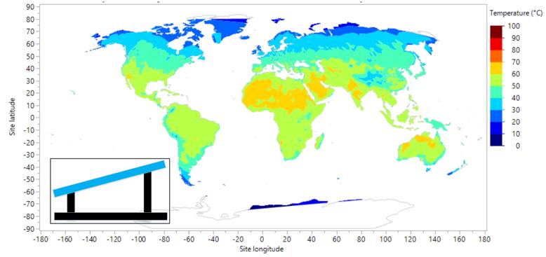

A.2SpatialdistributionoftheKöppenclimatetypesfortheperiodfrom1901to2010
This section is applicable to CS6R-MB-HL and all CanadianSolarmonofacialmoduletypesreferredtoin thisinstallationmanual.
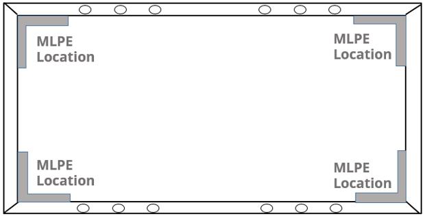
Module-levelpowerelectronics(MLPE)aredevicesthat can be incorporated into a solar system to improve its performance in certain conditions (especially where shade is present) and to reduce shock hazard for emergency responders. MLPE devices can be supplied asa‘retro-fit’systemmadebythird-partysupplier.
Module certification testing does not include MLPE devices.
When installing MLPE devices with Canadian Solar modules, follow the instructions of the MLPE supplier and the specific requirements given below. Ensure electrical parameters and limitations of the MLPE devices and the Canadian Solar modules are suitable foroneanother.
Failure to comply with these instructions will void the CanadianSolarwarranty.
INSTALLATION
When choosing to mount the MLPE device to the moduleframe,followtheMLPEsupplierinstructionsto ensure optimal mounting of the MLPE device and preventanyslippageduringoperation.
Canadian Solar recommends the MLPE device be installedclosetoacornerofthemoduleframe.
When choosing to mount the MLPE device to the mounting structure, please refer to the instructions providedbytheMLPEsupplier.
Do not cover the module nameplate or junction boxes when installing the MLPE devices on the rear of the modules.
Do not use frame mounting holes to install the MLPE device.
DonotdrillextraholesintheframetoinstalltheMLPE device.
ThedistancebetweentheMLPEdeviceandthemodule backsheetshouldbelargerthan20mm.
C.1.0GENERALINFORMATION
According to the specific conditions stipulated in the Canadian Solar installation manual and general warranty statement, installation of Canadian Solar PV modulesincoastalareasshallstrictlyfollowthismanual
This annex has been created to facilitate approval for customer PV installations located in coastal areas. It lays down general requirements to ensure that Canadian Solar PV modules are installed properly and reliably in coastal areas, which include but are not limitedtorelevantanti-corrosionprinciplesforboththe modulesandassociatedmountingsystems.Thisannex summarizes the key technical requirements stipulated by well-known international standards and explains howtheyapplytophotovoltaicsystems.
The word “coastal areas” in this manual refers to areas closetosalt-waterbodies,e.g.,seaandoceans.
The word “coastline” in this manual refers to the area wherethelandmeetstheseaduringhightide.
In this manual, “distance from the modules to the coastline” refers to the shortest distance between the photovoltaicmodulearrayandthecoastline.
Please read this annex carefully and strictly follow any relevant instructions prior to installing Canadian Solar modules in coastal areas. Failure to follow these instructionsandothergeneralanti-corrosionprinciples may result in corrosion damage to the photovoltaic modulesand/ortheirrackingsystemsandwillvoidthe Canadian Solar limited product and performance warranty. For further inquiries, please contact our customer service department or our local representativesformoreinformation.
The reliability of photovoltaic modules strongly dependsontheirdistancefromthecoastline.Different coastal land areas are defined according to how far away from the coastline they are; Canadian Solar generally classifies onshore PV installations according tofourdifferentgroups:
Installationmethod Requirements
Pile-basedinstallation
Distancefromthemodulesto thecoastline(X:meters)
0 ≤ X ≤ 20m
20m < X ≤ 100m
100m < X ≤ 500m
>500m
Type II anti-corrosion PV modules shall be used. Installations must comply with theinstructionslistedundersectionsC.2.1/C.2.2/C.2.3/C3.0.
Requirements
TypeIIanti-corrosionPVmodulesshallbeused.Installationsmustcomplywith theinstructionslistedundersectionsC.2.1/C.2.2/C.2.3/C3.0.
TypeIanti-corrosionmodulesshallbeused.Theseinstallationsmustcomply withtheinstructionslistedundersectionsC.2.1/C.2.2/C.2.3/C3.0.
TypeIanti-corrosionmodulesisrecommended.Itisrecommendedtofollowthe instructionslistedundersectionsC.2.1/C.2.2/C.2.3/C.3.0.
Pleasefollowsection7.0
Anti-corrosion modules are specially designed for coastal areas, of which the materials are specially
selected to meet the requirements of anti-corrosion installationincoastalareas.
“Pile-based installation” modules are supported by a certainheightofpilesabovethesealevel.
In all costal applications specified in this annex, the PV modules are prohibited from contacting the highest watersurfaceduringhightide.
Local conditions strongly influence the salt deposition rate, which is particularly, but not exclusively, dependentonspecificregionsand localwind patterns. Canadian Solar reserves the right to adapt the above definition to individual cases. Please contact your local representative to confirm which category your PV systemfallsunder.
Please consult the Canadian Solar technical support department or your local representative for more informationoninstallinganti-corrosionmodules.
Donotscratchorbreakthecorrosion-resistantcoating on the modules or mounting systems during installation.
Do not change the structure of the module, eg. by drillingholesintothemoduleframe.
Process and specifications for all components must comply with relevant international anti-corrosion standards.
Maintainthecorrosion-resistantcoatingregularly.
The module (including glasses, junction boxes and connectors)areprohibitedfromlong-termexposureto environments containing sulfur, strong acid, strong alkalis, or other corrosive risks. Avoid contact with organic solvents that can harm the anti-reflective

coating on the front glass, junction boxes and back polymersheets.
Before installation, the connectors are protected by dustcaps.Uponremovalofthem,immediatelyconnect the connectors to prevent water, mud, and other contaminationsfromcorrodingthepins.Forenhanced corrosion resistance, application of heat shrink tubing after installation is recommended to protect the connectors. Detailed installation steps are available from Canadian Solar upon request. It is strictly prohibited to usethe connectors or heat shrink tubing underwater.
All general requirements listed in the Canadian Solar manual should be applied when installing anticorrosionmodules.
C.2.2SPECIALANTI-CORROSIONMETHODSFOR MOUNTING
Use mounting components that contain the same metals or metals with a similar electrochemical potential.Themetal’scoatingalsoshouldbetakeninto account. There may be a big difference between the electrochemical potentials of two different coating materials. The potential difference between the support, fastening or grounding structure and the metalframeshouldbelessthan0.6V(refertoUL2703).
If the potential difference exceeds 0.6 V, please add insulation layers (e.g. insulation gaskets or insulation coatings) to isolate the two metals Insulation gaskets canbemadeofmicalaminates,siliconresinorfluorinebased materials. Special insulation coatings like Dacro orOTCcanalsobeapplied.
If the anti-corrosion coating is worn due to external forces,itneedstoberepairedpromptly.
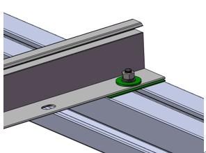
Werecommendtwospecialanti-corrosionmethodsfor protectingthesystem’sgroundingdevices.Pleaserefer totheinstructionsinthetablebelow:
Item MethodA
Coating components Fluorocarbonvarnish (onelayer)
Coatingthickness 40µm
Paintinginterval /
General requirements
Maintenance period
MethodB
Layer1(metalside):epoxyzincrichprimer
Layer2(middlelayer):fluorocarbonfinishpaint
Layer3(airside):fluorocarbonvarnish
Layer1(metalside):40µm
Layer2(middlelayer):40µm
Layer3(airside):40µm
Followthesupplier’sgeneralrequirementswhenpaintingthethree coatinglayers.Applythemiddlelayer24hoursafterpaintinglayer
1.Painttheairsidelayer6hourslaterafterpaintingthemiddle layer.
Cleanthegroundingcomponentsandmakesurethattheyaredryandclean.Thecoatingmust coverallthegroundingcomponentsandjunctionareasofthemoduleframeormounting system.Pleaserefertothefigurebelowformoredetails.
Thecoatingshouldbeappliedinadryatmosphere(atleast24hours)underthefollowing conditions:relativehumidityRH≤75%,ambienttemperatureT>5°C.
Threemonths
Fiveyears

C.3.0ANTI-CORROSIONSUGGESTIONSFORTHE RACKINGSYSTEM
The warranty does not cover the damage to the mounting system caused by corrosion if the mounting system is not provided by Canadian Solar To prevent salt-mist corrosion, Canadian Solar requires strict compliancewiththefollowingprinciples:
Use approved corrosion-resistant materials (e.g. stainless-steel SUS 316 or carbon steel with a hot-dip
Hot-dipgalvanizing (carbonsteel)
galvanizedcoating)foranyrackingorBOScomponents usedincoastalareas.
Toavoidtheattenuationofbolttorquecausedbyeddy currentsduringmoduleinstallation,itisrecommended touseanti-looseningbolts.
The minimum coating thicknesses for hot dip galvanized and anodizing oxide components must comply with the standard minimum requirements stipulatedinJISH8641andJISH8601.
(76µm)
ISO1461 JISH8641
Anodizingoxide (aluminumalloy)

Before installing any modules, contact the appropriate authorities to obtain any relevant approvals and learn of any site, installationandinspectionrequirements.
When applying coating materials, workers must follow applicable health and safety legislation and apply all respective preventive and proactive measures describedwithin.
Canadian Solar shall not be held responsible for damages of any kind, including but not limited to, bodilyharm,injuryanddamagetopropertyasaresult ofhandlingmodules,installingsystems,orcompliance ornon-compliancewiththeinstructionssetforthinthis manual.
Rev1.0integratedversionwasfirstreleasedinJanuary,2023
Rev1.1wasreleasedinMarch,2023
Rev1.2wasreleasedinApril,2023
Rev1.3wasreleasedinJune,2023
Rev1.4wasreleasedinAugust,2023
Rev1.5wasreleasedinSeptember,2023
Rev1.6wasreleasedinSeptember,2023
Rev1.7wasreleasedinOctober,2023
Rev1.8wasreleasedinDecember,2023
Rev2.0wasreleasedinFebruary,2024
Rev2.1wasreleasedinApril,2024
Rev2.2wasreleasedinJuly,2024
Rev2.3wasreleasedinSeptember,2024
CSISolarCo.,Ltd.
199LushanRoad,SND,Suzhou,Jiangsu,China,215129
www.csisolar.com

The advantages of a central inverter with the modularity of the string inverters.
Designed to be easily replaceable on the field with a safe, reliable, and fast Plug&Play assembly system.
Includes up to 4 FRUs (Field Replaceable Units).
Remove no-load losses.
These product has the following characteristics 4
The turn-key solution, simplifies the task of designing the installation, and reduces connection costs. 1 3 2
The Bus Plus feature allows the connection of up to four Freemaq DC/DC converters. It’s the most cost-competitive solution for solar-plus-storage retrofits. Combine solar and storage.
Disconnecting the power station from the grid and taking the medium-voltage transformer out of the circuit, eliminating the continuous energy cost of no-load losses.

Capable of operating on any power system, Offering advanced grid support functionalities to comply with the most restrictive grid codes.
The most innovative cooling system.
Our own air ventilation system provides a constant flow of clean air inside the equipment, without the need of liquid cooling.


When the unit is not actively exporting power, the inverter can import a small amount of power to keep the inverter internal ambient temperature above -20°C, without using external resistors.
It also can shift to reactive power compensation mode.
The 3 level IGBT topology reduces stage losses, increases inverter efficiency, and minimizes total harmonic distortion. High efficiency to deliver the lowest cost of energy (LCOE).
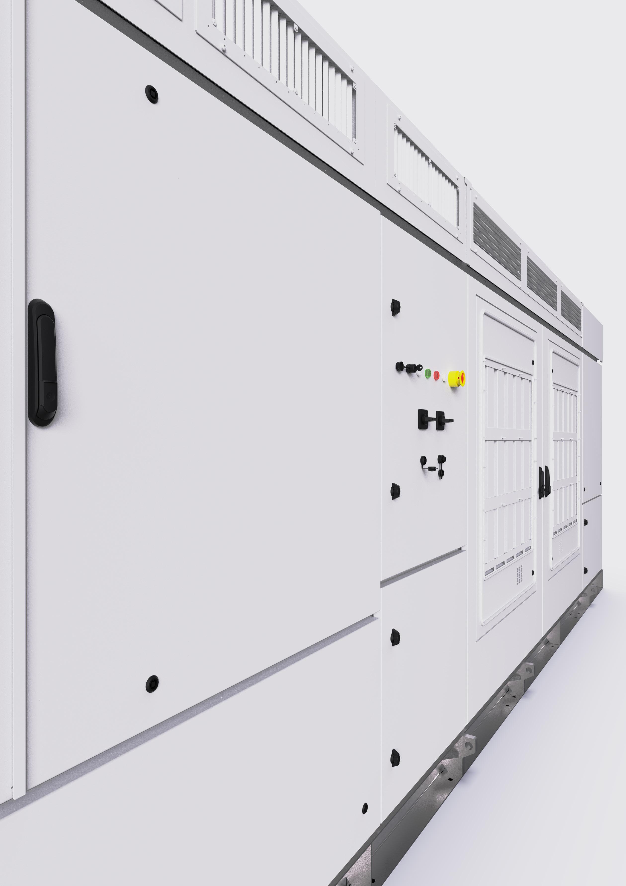
STRING INVERTER CABINETS
The ultimate medium-voltage inverter 4.2
DC-coupled storage system from 1200 kW to 4800 kW

Can reach up to a nominal power of
AC Output Power (kVA/kW)
@40°C[1] 4200
AC Output Power (kVA/kW) @50°C[1] 3900
Operating Grid Voltage (kV)[2]
EFFICIENCY
CABINET
ENVIROMENT
REFERENCES
FS4105M
AC Output Power (kVA/kW)@40°C[1] 4105
AC Output Power (kVA/kW)@50°C[1] 3810
Operating Grid Voltage (kV)[2]
OUTPUT
34.5kV ±10%
Operating Grid Frequency (Hz) 60Hz
Current Harmonic Distortion (THDi) < 3% per IEEE519
Power Factor (cosine phi)[3] 0.5 leading … 0.5 lagging adjustable / Reactive power injec- tion at night
DC Voltage Range[4] 934V - 1500V
Maximum DC Voltage 1500V
Number of Inputs Up to 40
Max. DC Continuous Current (A)[5] 4590
Max. DC Short Circuit Current (A)[5] 6940
Number of MPPt (floating systems) 1, optionally 2 or 4
Number of Freemaq DC/DC[5] Up to 2 (Bus Plus Basic) or 4 (Bus Plus Advanced)
Efficiency (Max) (η) 97.8% including MV transformer
Euroeta (η) 97.51% including MV transformer
Dimensions [WxDxH] (ft) 21.3 x 6.5 x 7.2
Dimensions [WxDxH] (m) 6.5 x 2.0 x 2.2
Weight (lbs) 30865
Weight (kg) 14000
Type of Ventilation Forced air cooling
Degree of Protection NEMA 3R
Permissible Ambient Temperature -35°C to +60°C, >50°C / Active power derating
Relative Humidity 4% to 100% non-condensing
Max. Altitude (above sea level)[6] 2000m
CONTROL INTERFACE Communication Protocol Modbus TCP Power Plant Controller Optional
Keyed ON/OFF Switch Standard
Ground Fault Protection GFDI and isolation monitoring device
Humidity Control Active heating
34.5kV ±10%
Operating Grid Frequency (Hz) 60Hz
Current Harmonic Distortion (THDi) < 3% per IEEE519
Power Factor (cosine phi)[3] 0.5 leading … 0.5 lagging adjustable / Reactive power injection at night
DC Voltage Range[4] 913V - 1500V
Maximum DC Voltage 1500V
Number of Inputs Up to 40
Max. DC Continuous Current (A)[5] 4590
Max. DC Short Circuit Current (A)[5] 6940
Number of MPPt (floating systems) 1, optionally 2 or 4
Number of Freemaq DC/DC[5] Up to 2 (Bus Plus Basic) or 4 (Bus Plus Advanced)
EFFICIENCY
CABINET
ENVIROMENT
CONTROL INTERFACE
PROTECTIONS
PROTECTIONS
General AC Protection & Disconn. MV switchgear (20 or 25 kA)
General DC Protection & Disconn. Fuses, DC switch-disconnectors
Overvoltage Protection Type 2 protection for AC and DC (optionally, Type 1+2 for DC side)
CERTIFICATIONS & STANDARDS Safety UL 1741 / CSA 22.2 No.107.1-16
Installation NEC 2020
Utility Interconnect IEEE 1547:2018 / UL 1741 SB
[2] Consult Power Electronics for other configurations.
[3] Consult P-Q charts available: Q(kVAr)=√(S(kVA)2-P(kW)2).
CERTIFICATIONS & STANDARDS
Efficiency (Max) (η) 97.76% including MV transformer Euroeta (η)
including MV transformer
Dimensions [WxDxH] (ft) 21.3 x 6.5 x 7.2
Dimensions [WxDxH] (m) 6.5 x 2.0 x 2.2
Weight (lbs) 30865
Weight (kg) 14000
Type of Ventilation Forced air cooling
Degree of Protection NEMA 3R
Permissible Ambient Temperature -35°C to +60°C, >50°C / Active power derating
Relative Humidity 4% to 100% non-condensing
Max. Altitude (above sea level)[6] 2000m
Communication Protocol Modbus TCP
Power Plant Controller Optional
Keyed ON/OFF Switch Standard
Ground Fault Protection GFDI and isolation monitoring device
Humidity Control Active heating
General AC Protection & Disconn. MV switchgear (20 or 25 kA)
General DC Protection & Disconn. Fuses, DC switch-disconnectors
Overvoltage Protection Type 2 protection for AC and DC (optionally, Type 1+2 for DC side)
Interconnect
REFERENCES FS4010M
AC Output Power (kVA/kW)@40°C[1] 4010
AC Output Power (kVA/kW)@50°C[1] 3720
Operating Grid Voltage (kV)[2]
34.5kV ±10%
Operating Grid Frequency (Hz) 60Hz
Current Harmonic Distortion (THDi) < 3% per IEEE519
Power Factor (cosine phi)[3] 0.5 leading … 0.5 lagging adjustable / Reactive power injec- tion at night
DC Voltage Range[4] 891V - 1500V
Maximum DC Voltage 1500V
Number of Inputs Up to 40
Max. DC Continuous Current (A)[5] 4590
Max. DC Short Circuit Current (A)[5] 6940
Number of MPPt (floating systems) 1, optionally 2 or 4
Number of Freemaq DC/DC[5] Up to 2 (Bus Plus Basic) or 4 (Bus Plus Advanced)
EFFICIENCY Efficiency (Max) (η)
CABINET
ENVIROMENT
CONTROL INTERFACE
PROTECTIONS
97.75% including MV transformer
Euroeta (η) 97.48% including MV transformer
Dimensions [WxDxH] (ft) 21.3 x 6.5 x 7.2
Dimensions [WxDxH] (m) 6.5 x 2.0 x 2.2
Weight (lbs) 30865
Weight (kg) 14000
Type of Ventilation Forced air cooling
Degree of Protection NEMA 3R
Permissible Ambient Temperature -35°C to +60°C, >50°C / Active power derating
Relative Humidity 4% to 100% non-condensing
Max. Altitude (above sea level)[6] 2000m
Communication Protocol Modbus TCP Power Plant Controller Optional
Keyed ON/OFF Switch Standard
Ground Fault Protection GFDI and isolation monitoring device
Humidity Control Active heating
General AC Protection & Disconn. MV switchgear (20 or 25 kA)
General DC Protection & Disconn. Fuses, DC switch-disconnectors
Overvoltage Protection Type 2 protection for AC and DC (optionally, Type 1+2 for DC side)
Safety
CERTIFICATIONS & STANDARDS
UL 1741 / CSA 22.2 No.107.1-16
Installation NEC 2020
Utility Interconnect IEEE 1547:2018 / UL 1741 SB
[1] Values at 1.00·Vac nom and cosφ=1. Consult Power Electronics for derating curves.
[2] Consult Power Electronics for other configurations.
[3] Consult P-Q charts available: Q(kVAr)=√(S(kVA)2-P(kW)2). [4] Consult
Global Innovation Leader for Trackers, Fixed Tilt & BOS
BEST QUALITY AND PRICED POST DRIVEN, FIXED TILT SOLAR RACKING SYSTEMS

• LESS POSTS WITH UNMATCHED SPAN
• POST BRACKET ADJUSTMENT HANDLE UP TO 15% EAST-WEST TERRAIN SLOPES AND UNDULATIONS
• Supports all commercially available poly, glass, and thin film modules.
• Rugged design enables 175 mph [78 m/s] wind and 90 psf [4,300 Pa] snow loads.
• Pull test and geotech services available.
• Galvanized Z purlins have integrated trays for easy wire management.
• 10° to 35° tilt with multiple inter-row spacing options.

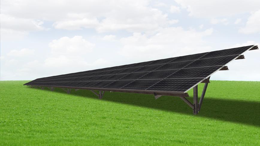


GameChange Solar HEADQUARTERS
230 East Ave, Suite 100
Norwalk, CT, USA
Phone: +1 (203) 769-3900
Fax: +1 (646) 607-2223
gamechangesolar.com
media@gamechangesolar.com
GLOBAL OFFICES
El Paso, TX
Florence, SC
Dublin, Ireland
Madrid, Spain
Wuxi, China
Bangalore, India
Dubai, UAE
Buenos Aires, Argentina
Johannesburg, South Africa
Newcastle, Australia
DISCLAIMER:
RESEARCH & DEVELOPMENT CENTER
Brimfield, MA, USA
SERVICE SUPERCENTERS
Lakeland, FL, USA
Mesa, AZ, USA
Santiago, Chile
Madrid, Spain
• Industry’s most flexible racking system handles undulating ground conditions.
• Three axes of adjustability demanded by installers for navigating real world site conditions where significant adjustability in the field is required.
• The unmatched span capability of MaxSpan™ means there are fewer foundations than competing systems, which means less posts and less post installation cost. As few as 180 posts per MW for 2 up in portrait. 130 posts per MW for 3 up in portrait.
• Over 5” [12.7 cm] vertical adjustment for fast top of post leveling.
• Up to 4’-0” [122 cm] high ground clearance to allow for snow and vegetation.
• 10° to 35° tilt with multiple inter-row spacing options.
• Accommodates for framed modules (including First Solar Series 6™) in 2 to 4 portrait and 4 to 8 landscape and multiple glass on glass module configurations including First Solar Series 4™
• Full layout and engineering analysis for every project.
• Integrated grounding and wire management.
• Wide flange and roll formed posts available.
• South facing and EastWest system option.
• Single and Dual Post configuration available.
• Pre-assembled “Swiss Army Knife” beam:
- One worker carry by weight.
- Just bolt it onto post extender, cut zip tie, swing braces and brackets into position, and bolt down.
- All hardware and brackets pre-attached and in assembly kit.
- Super simple staging: one unit replaces previous staging of nuts, bolts, brackets, braces, and beam.
• MaxSpan™ with TwistClamps™:
- TwistClamps™ Increase Panel Install Speed 400%.
- 400 modules per worker day versus 100 with nuts and bolts.
- One worker inserts and twists all pre-assembled TwistClamps™ into purlins.
- Follow-up workers slide modules under TwistClamps™
- Workers then use torque wrenches to do just one final rotation on the pre-attached serrated flange nyloc nut to reach required torque and simultaneously grounds the module
- Workers can slide modules north and south when TwistClamps™ are used so that the modules always align.
• Meet IBC and ASCE standards for structural loading.
• Electrical bonding with GameChange top mount clamps or star washers included.
• ETL / UL 2703 tested (similar to the relevant sections of IEC 61215 & 61730).
• Wind tunnel tested by industry leader CPP.
• Independent assessment by Black & Veatch.
• Designed and engineered in the US. Includes a 20-year warranty.
• PE Stamped Drawings - Design loads according to local building codes: ASCE 7, NBC, Eurocode, AS1170, IS875, and SANS10160.
• 100% code compliant designs for any locality.
• Vertical and lateral capacity of the post is determined by pull test.
• Test data is then analyzed by our in-house engineering team in parallel with geotechnical report to identify the most efficient embedment depths, spans and post type.
• Post: G235 [55 μm] galvanized steel (HDG ASTM A123 option also available).
• Galvanized Purlins, NS Beam, Brace: G90 [20 μm] galvanized steel. Standard up to G180 [40 μm] special order.
• Star bolt or ETL / UL top mount teethed module clamp: stainless steel & magnicoat.
• Proprietary Integrated-Hardware™ for faster structure assembly, module mounting and reduced O&M cost. Oversized Serrated Flange Nyloc Nut and Oversized Flange Star Bolt with integrated star washer eliminates the need for washers and star washers.


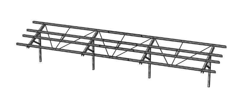
Please carefully follow this manual to learn how to correctly install the GameChange Solar Max-Span™ Ground System. The Max-Span™ Ground System is engineered and tested to withstand wind and snow loads to specification when installed properly. Failure to precisely follow the install manual and to install the racking system properly may decrease the performance of the installation and will void the warranty.
This is the generic manual and it includes all components utilized in all variations of the Max-Span™ Ground System Please refer to your particular permit/layout detail sheets and bill of materials for the specific components for your system as some components may not be required.
The installer is responsible for the following:
Following all instructions in this Install Manual
Utilization of only qualified personnel
Using only GameChange parts. Using other parts to complete the installation as substitutes may void the warranty.
Making sure the ground structure (notably in the case of a capped landfill) can support the loading resulting from the Max-Span™ Ground System
Following all safety procedures as outlined in this Install Manual, both for mechanical and electrical aspects of the solar PV array installation
Following all safety instructions that are required by relevant local, regional and national organizations
Materials are packaged in optimal manner to protect components. Do not un-package until time of installation. Un-packaging and restacking may cause damage to components.
General safety precautions:
Plan for safe practice during any installation activity with respect to hazards from tripping, falling, lifting, repetitive stress, and any overhead or electrical hazards. Refer to OSHA safety guidelines.
Metal components often have sharp edges. Handle carefully! Wearing gloves is good practice.
This document is not prescriptive regarding safety and does not purport to address all the safety concerns that may arise with its use. Contractors should become familiar with all applicable safety, health and regulatory requirements before beginning work.
Electrical safety notice – The Max-Span™ Ground System is a mechanical system and contains no “live” parts. Mechanical installers and electricians should coordinate in order to ensure that all personnel are aware of electrical hazards that may result once panels have been placed on the racking structure.
Build rate – Estimated mechanical installation rate (racks and panels per day) for an array consisting of commercial-class modules installed with the Max-Span™ Ground System and assuming a well-equipped five-person crew working 8 hours / day with full task interchangeability: approximately 227 panels and racks per day. 15 men install 1.05 MW per week with 300 watt modules.
Field modifications and Work arounds – Unauthorized field modification and workarounds of Gamechange components or assemblies may affect GameChange warranty coverage. Provide marked up drawings for Gamechange’s review, comment and approval prior to attempting. Installers laying out or installing arrays may encounter undocumented or unexpected obstacles requiring a work around. Since PV arrays are intended to be primarily regular and repeating structures, work arounds should be brought to the attention of GameChange personnel prior to being done. If approved by GameChange, they should be noted on working drawings.
Suggested driver torque
1/4-inch hardware (7/16-inch driver), use 6 ft-lbs
3/8-inch hardware (9/16-inch driver), use 20 ft-lbs
3/4-inch hardware (1 1/8-inch driver), use 140 ft-lbs
All regional safety requirements shall be followed when installing the Max-Span™ Ground System. All equipment/tools shall be properly maintained and inspected prior to use. This installation manual is intended for use by professional installers with a working knowledge of construction principles. If the install manual is not followed completely the warranty may be voided and the solar system may not operate optimally.
The following tools are required for the installation of the Max-Span™ Ground System:
String line, 48 inch long level and 30 foot tape measure
Anti-seize may be beneficial to prevent galling for bolts used to mount panels, but is not required
GameChange rack materials (see below)
Wrenches and deep and short sockets and drivers: 7/16 inch (for 1/4-inch hex bolts and nuts), 9/16 (for 3/8), and 1 1/8 (for 3/4)
Inclinometer of level with digital degree read out
Suggested driver torque
1/4-inch
3/8-inch
The Max-Span™ Ground System contains the following parts:
(This is the generic manual and it includes all components utilized in all variations of the Max-Span™ Ground System Please refer to your particular permit/layout detail sheets and bill of materials for the specific components for your system as some components may not be required.)
StickyPileTM Post (GC61) NS Beam (GC62H)

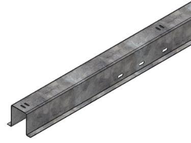
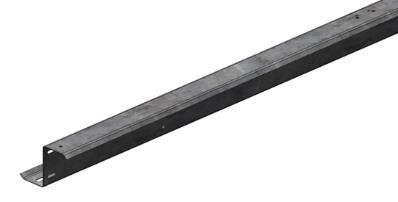
req’d)

req’d)


req’d)
Brace for NS Beam (GC64HX)
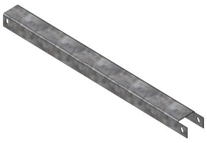


Associated Hardware for Posts (Piles), Braces, Beams, EW Purlins, and other components:
Flange nuts, and hex bolts (or flange bolts); 3/8-16 x 1 inch, and 3/4-10 x 1 1/2 inch: Magnacoat
Washers 3/8 and 3/4 inch; Hot dip galvanized, magnacoat or stainless steel
Panel Mounting Hardware:
Stainless steel:
o Hex bolts - 1/4-20 x 3/4 inch long
o Flange nuts (1/4-20)
o External tooth star washer (5/16 inch)
1.0 Measure the footprint of the array according to the installer’s design and site plan.
2.0 Find the edges of the array according to provided design.
3.0 Drop a string line on the southern edge.
4.0 Mark Post Locations with locator nails according to array plan starting at south-east corner of array -Make sure define distance between foundations is measured from center of post to center of next post along the ground (not from plan view). Otherwise foundation locations will creep if there is rolling terrain since plan view does not factor in dimensions differences caused by terrain. This could make purlin attachment more difficult.
5.0 Install first Post to the proper height above the ground
5.1 There is an adjustment range given by GameChange for posts with a minimum embedment depth governing on one side and the distance for ground clearance requirement on the other.
5.2 This is typically from 4 to 8 inches.
5.3 It is good to vary embedment depth from minimum to maximum allowed on this range in order to align tops of piles in a flat or relatively smoothly sloping fashion as per the ground being flat or sloping.
6.0 Make sure the two longer sides (approximately 6-inch) face East-West, and the open side faces north North↑

7.0 Make sure next Posts are installed at specified distances from marked locations:
7.1 East-west +/- 1 inches The racking system allows for +/- 2 inches but this will make more adjustment of purlins necessary and slow down installation
7.2 North-south +/- 1 inch
8.0 Make sure posts are squared to within +/- 1 degree to the azimuth of the array
9.0 Tops of the posts are leveled to be at a consistent height or slope depending on the topography of the land (with a tolerance of optimally +/- 1 inch). Note that embedment depth will vary. GameChange provides range of embedment depth to allow for this. Be careful to always meet minimum embedment depth.
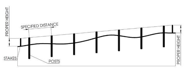
10.0 Make sure post is plumb, optimally +/- 1 degree so long as:
10.1 Not more than +/- 1 1/2 inches on east to west direction at top of post (from the proper post location marked on ground). The racking system allows for +/- 2 1/2 inches but this will make more adjustment of purlins necessary and slow down installation)
10.2 Not more than +/- 1 inch north to south direction at top of post (from the proper post location marked on ground)
Inform Game Change immediately if refusal is encountered when driving posts. Refusal is defined as a blow count of 10 or more per inch (120 blows per foot). Refusal of posts shall be addressed as follows:
Option 1 – Use post at shallower embedment depth
a) Based on the embedment of the post at time of refusal and the location of the post relative to the array, GameChange engineering staff may determine it to be acceptable to leave the post at the shallower embedment depth. If instructed by GameChange engineering staff, cut the top of the post to the appropriate height and field drill bolt holes for connection to the beams per post drawings.
b) Pull testing may be required to confirm the post at the shallower depth has sufficient resistance to the design uplift and lateral forces. Pull test procedures, including test loads, will be provided by GameChange engineering staff.
Option 2 – Install post in Aggregate Base Course
a) Pull Post out using a crane attached to the topmost slots (or equivalent method)
b) Drill hole for Post using a 10” drill to the depth prescribed for Post embedment depth within tolerances.
c) Fill hole with aggregate base course. Depending on site conditions, this method may not be applicable, or compaction of the aggregate fill may be required. Consult GameChange engineering staff for more information.
d) Drive post at original location, through aggregate, in accordance with typical post installation instructions above.
Option 3 – Install shorter post in concrete pier
a) Pull Post out using a crane attached to the topmost slots (or equivalent method)
b) Drill hole for Post using a 12” drill to the depth prescribed for Post embedment depth within tolerances.
c) Insert Post into drilled hole and hold plumb. Temporary wooden bracing supports may be used for this.
d) Fill with 4,000 psi concrete, in consultation with GameChange to amount of concrete and method of installation.
Installing Posts using drill and concrete pouring method to ensure proper Post top alignment:
Attach tape to the drill bit (for pre-drilling holes for pile holes to be filled in with concrete) so that the distance from the tape to the bottom of the drill bit is the same as the height of the post.
Set a stake at each end of a row line.
Attach a string (or aircraft cable and use come-alongs to keep taught) from one stake to the other, and make sure it is at the proper post height above the ground.
Dill holes vertically and plumb until bottom of the tape is level with the string.
Remove drill and place post in hole.
This will align every post to a consistent slope
Embedment depth will vary, make sure minimum embedment depth meets GameChange requirements. Please consult with GameChange for more detail.
Suggested driver torque
1/4-inch
3/8-inch
3/4-inch
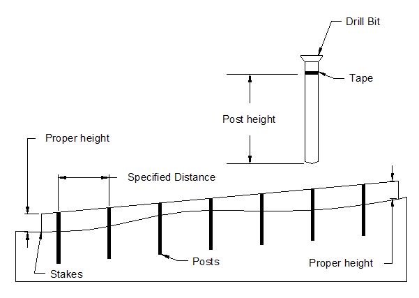
(7/16-inch
(9/16-inch
1/8-inch
Deformation at the top of the piles rarely occurs, and typically only when piles are driven into rock, and is minor and easily remedied. Deformation could cause problems for the installation of the NS Beam. If any deformation at the top of the piles occurs during installation:
a) If mushrooming is locally isolated above any slots or features and within 1/8 inch of the original drawing dimension (4 15/16”), use a hammer (or equivalent equipment) to reshape the top end of the Post back to within 1/16 inch of the original drawing dimension.
b) If piles are deformed more than 1/8 inch then consult with GameChange regarding re-use.
If there is any cracking of galvanized coating on piles make sure to wire brush then paint area with zinc rich paint.
Suggested driver torque
1/4-inch
3/8-inch
3/4-inch
1.0 Place NS Beam on top of Post such that longer part is to South, aligning the 3/4-inch mounting hole with 3/4-inch width slot on top of Post.
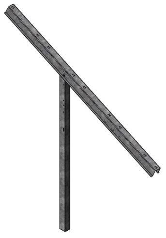
2.0 Attach NS Beam to Post using 2.1 3/4-inch bolts
2.2 3/4-inch washers (under bolt heads, on NS Beam side)
2.3 3/4-inch serrated flange nuts (inside Post)
2.4 3/4-inch washers (under serrated flange nuts, inside Post)
2.5 Leave hand tight to allow for adjustment in later steps

3.0 Align 3/4-inch hole on Brace to 3/4-inch width slot in the middle of the Post Attach Brace to Post using 3.1 3/4-inch bolts
3.2 3/4-inch washers (under bolt head, on Post side)
3.3 3/4-inch serrated flange nuts
3.4 3/4-inch washers (under serrated flange nuts, inside Brace)
3.5 Leave hand tight to allow for adjustment in later steps
Suggested driver torque
1/4-inch hardware (7/16-inch driver), use
3/8-inch hardware (9/16-inch driver), use
3/4-inch hardware (1 1/8-inch driver), use

4.0 Align 3/4-inch slots on Brace to 3/4-inch slots on NS Beam.
Attach Brace to NS Beam using 4.1 3/4-inch bolts
4.2 3/4-inch washers (under bolt head, on NS Beam side)
4.3 3/4-inch serrated flange nuts
4.4 3/4-inch washers (under serrated flange nuts, inside Brace)
4.5 Leave hand tight to allow for adjustment in later steps

Note: Make sure to review assembly print for specific job and attach to hole that results in tilt as required for installation
5.0 Repeat steps 1.0 – 4.0 for NS Beam and Brace on adjacent Posts
When installing Beams; make sure all Beams are at the tilt as required for the installation.
The NS Beams have to be oriented correctly in the North-South direction, aligned properly in the East-West direction, and are to be at a consistent level height or slope Using a string line will be helpful to do this.
Tighten hardware to specifications.

Suggested driver torque 1/4-inch
1.0 EW Purlins attach to NS Beams using:
1.1 Two 3/8-inch bolts
1.2 Two serrated flange nuts
1.3 One Purlin Washer (must use Purlin Channel Washers for 16 gauge Purlins)
1.4 One Wide Beam Washer
2.0 EW Purlins should be installed facing uphill or downhill as shown in drawing set for each individual system provided as by GameChange.
3.0 Post distances may vary due to site conditions or Post installation variances, therefore do not install all table purlins first. If you install all table purlins first, you will likely need to go back and take some of these off and reinstall if connector purlins do not reach. It is better to install only a few table purlins ahead and then go across the row using table then connector purlins as you go.
4.0 Attach first EW Purlin at center holes on the southernmost position to the first and second NS Beams using center set of holes for EW Purlin attachment.
4.1 Hardware attachment sequence:
4.1.1 Insert 3/8-inch bolt through Purlin Washer nearest to EW Purlin wall, EW Purlin, NS Beam, and Wide Beam Washer. Make sure Purlin Washer is pushed up tight against the wall of the Purlin, this is important.
4.1.2 Attach 3/8-inch flange nuts below NS Beam
4.1.3 Insert 3/8-inch bolt through EW Purlin furthest from EW Purlin wall, NS Beam, and Wide Beam Washer
4.1.4 Attach 3/8-inch flange nuts below NS Beam
4.1.5 Finger Tight on hardware
4.1.6 After Panels mounted and Purlins properly aligned, tighten hardware to specification, using driver to turn bolt head.
4.1.7 Alternatively bolts may come up and flange nuts be above purlin


4.2 Then, noting the length of the connecting EW purlin, attach the second southernmost EW Purlin to the third and fourth NS Beams
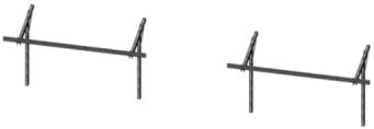
4.3 For completing EW Purlin installation on tables:
4.4
4.3.1 Install the third EW Purlin up the NS Beam.
Suggested driver torque
1/4-inch
3/8-inch
(7/16-inch
1/8-inch
4.3.2 Using the tape measure to confirm the table is square(by cross measuring or golden 345 triangle.
4.3.2.1 May need to tighten bolts to hold the table square.
4.3.3 Install the second EW Purlin and the fourth EW Purlin.
4.3.4 Use a tape measure or t-square to make the second and fourth EW Purlins are square with the first and third.
Attach connector EW Purlin to between the table EW Purlins. There will be a nominal drop of 1/8 to 1/4 inch from one purlin to the next, which will result in a small corresponding drop from one panel to the next at these junctions. This is normal for connecting systems and is not a shading or functional issue. Try to attach slots at center if possible. This will make for better spaced panel install.
4.4.1 Hardware attachment sequence:
4.4.1.1 3/8-inch bolts (or serrated head bolts),
4.4.1.2 washers (on either side, one under the bolt head and another under the nut) and
4.4.1.3 serrated flange nuts.
4.4.1.4 Alternatively bolt direction may be reversed.


Connecting purlins allow for articulation to handle east-west slopes of up to 8%

4.5 Repeat for all table EW Purlins and connecting EW Purlins
4.6 Make sure to attach the alternating table EW Purlins and connecting EW Purlins starting at one end of row and continue to the other end of the row.
4.7 Do not attach table EW Purlins at several points along the row in isolated table format or you may not be able to utilities all of the EW adjustment features provides as easily as if you start on one end and work your way across.
Suggested driver torque 1/4-inch
Attaching the Bend Strap
1.0 Bend Straps shall be installed on the underside of the EW Purlins approximately midway between two adjacent Beams. Use 3/8-16 hex bolts and serrated flange nuts. Torque to specification
Attaching the Roll Ties
2.0 Roll Ties shall be installed on the EW Purlins approximately midway between two adjacent Beams (one on either side of the Bend Strap) Assembly drawing will identify where the Roll Ties are to be installed. One Roll Tie will be installed from the top of the southern Purlin web to the bottom of the northern Purlin leg. The other Roll Tie will be installed from the top of the northern Purlin web to the bottom of the southern Purlin leg. Use 3/8-16 hex bolts and serrated flange nuts The Roll Ties must be taut, this is very important Torque to specification.

Attaching the Roll Straps
3.0 Roll Straps shall be installed at both ends of first and third EW Purlins to the Beams. Use 3/8-16 hex bolts and serrated flange nuts. The Roll Straps must be taut, this is very important. Torque to specification. Bolts through purlin may be installed in either direction with flange nut on either side, however bolts through beam must have head above beam and Flange nut under Beam. Torque to specification.
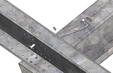
Attaching the Purlin Angle
4.0 Purlin Angles (if required) shall be installed on the underside of the EW Purlins at the holes next to the NS Beams on the upper EW Purlins, holes near the center of the lowest EW Purlin, and the respective holes that line up for the 2nd and 3rd Purlin. Use 3/8-16 hex bolts and serrated flange nuts. Torque to specification.

Suggested driver torque
1/4-inch
3/8-inch

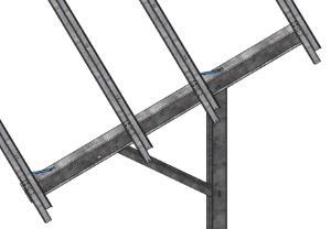

3/8-inch
Panel Mounting Hardware:
Stainless steel:
o Hex bolts - 1/4-20 x 3/4 inch long
o Flange nuts (1/4-20)
o External tooth star washer
1.0 Attaching first panel to EW Purlin through mounting holes in EW Purlins nearest to NS Beam:
1.1 Place star washer at one location per panel inside panel frame.
1.2 Insert hex bolt through the EW Purlin, through the mounting hole in the back of the panel, then through the star washer.
1.3 Attach with a flange nut on end of bolt inside panel frame over star washer.
1.4 Tighten bolt to specification.
1.5 Repeat 1.1 through 1.4 for three more bolts for each panel without using star washer.
Bottom mount method: Portrait configuration:
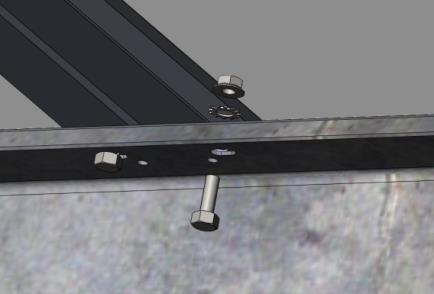

Alternate Panel Mounting Method: If panel mounting hole diameter or slot width is 0.28” or less, the orientation of the bolt and nut can be flipped such that the stack-up order from top to bottom is: hex bolt head, star washer, panel frame mounting hole, EW Purlin mounting hole, and flange nut.
2.0 Repeat for all panels
3.0 For bottom mount attachment of panels GameChange typically provides slotted panel mounting holes to enable panel adjustment in case purlins are not perfectly aligned due to rolling or otherwise uneven ground situations.
4.0 It is the customer’s responsibility to make sure to follow panel spacing guidelines if any are given by panel vendor in their specification sheet or elsewhere, otherwise panel warranty could be voided. In all cases make sure panel spacing is the greater of 1/8 inch or the minimum called out by the panel vendor. This will allow for thermal expansion of panels. GameChange systems typically enable ¼ inch panel spacing if aligned properly.
4.1 Spacing between panels can be set by placing a temporary spacer such as bolt shaft or plywood of same thickness as required for panel spacing between panels while they are being installed. This spacer should be removed after panel installation is complete.

Suggested driver torque
1/4-inch
3/8-inch
It is the installers responsibility to install wiring properly. Care should be taken fasten wire firmly in place to prevent movement or chaffing against metal parts over time. Wires should be checked on a routine basis to make sure they remain firmly attached and in place.
The modules and EW Purlins are all bonded together across the entire row, East and West.
To achieve grounding of the system, GameChange recommends installing Cooper, Burndy, or Eaton UL approved grounding lug(s) with 1/4-inch bolts as in accordance with NEC Article 690 to the Post below the last EW Purlin which has panels attached to it which are to be bonded, using 8 gauge copper wire.
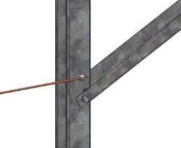
The Purlin to Purlin bonded connection is rated for up to 25 amps. Therefore, conductors with expected currents greater than 25 amps may not be installed on the racking system without installing additional grounding measures.
The entire system needs to be grounded from a single point to an appropriate grounding source.

**Please confirm with an electrician, as this is their responsibility**
In case of a configuration where there is a break in the array, UL 2703 listed jumpers (e.g., Burndy WILEYBRAID) may be used to bond one segment of the array to the next (only one jumper in between two tables). Install jumpers via unused or field-drilled holes on the Purlin, Beam, or Post, and using UL 2703 approved attachment methods.
The Max-Span™ Ground System is a simple, affordable, easily installed ground-based solar mounting system. Components are made from galvanized and stainless steel. Max-Span™ Ground System may be installed on solar arrays of up to 200,000 solar panels each (approximately 50 MW). Maximum panel size for the system shall be 45 x 82 inches. Slopes up to 10% are allowable under all normal conditions for continuous systems, and up to 30% for table systems only in consultation with GameChange personnel.
All materials are made from non-corrosive materials, galvanized, magni coated or stainless steel, with a product warranty of twenty (20) years.
Suggested driver torque
3/8-inch
Make sure to install system within several days of receipt of components. Storage of components in a damp or wet environment can lead to white rust on galvanized parts as well as other damage on other protective coatings which can lead to accelerated corrosion of components, and void the warranty. Galvanization is especially prone to white rust when components are still bundled because the zinc coating requires airflow over its surface to establish its protective patina, otherwise water can cause corrosion of the zinc and it has no protection against it in enclosed spaces, such as those between parts that are bundled.
Proper preparation of surface must be ensured for a well-performing system to be installed. For continuous racking without breaks, ground must be at an east-west slope not to exceed 5 percent to minimize east /west shading from panel to panel.
Grading of the ground on the installation area is the responsibility of the customer and should be completed properly to enable the slope tolerance for the Max-Span™ Ground System.
General guidelines include:
Choose a clear area free of shading
Suggested ten (10) foot border surrounding array
Proper preventative maintenance must be conducted or warranty may be voided. After installation of the Max-Span™ Ground System, installer must annually monitor for any surface rust that may occur over time due to scraping of the components or for any other reason. While the extensive galvanizing protection should minimize any such rusting, it is essential that preventative maintenance be performed annually to include:
Identifying any rust areas
Wire brush the rust area to remove all rust
Coat the area with 70%+ zinc rich or equivalent field life paint
This step is not required if rust is limited to edges which were cut during fabrication
After extreme wind turbulence (in excess of 80% of design wind speed), and on an annual basis, an inspection must be done for mechanical movement (which could also be due to any reason including thermal expansion and contraction). Any mechanical movement must be rectified. Torque settings must be checked for all hardware. All Clips shall be checked to make sure there is no gap between the side of the Clips and modules.
It is estimated that two qualified persons should be able to properly inspect and maintain racking for approximately 1,000 panels per day.