Representative Components
Solar Panels
Q.PEAK DUO ML-G12S SERIES
675-690 Wp | 132 Cells
22.2 % Maximum Module Efficiency
MODEL
Q.PEAK DUO ML-G12S.3 / BFG

The ideal solution for:
Bifacial energy yield gain of up to 21 %
Bifacial Q.ANTUM solar cells make efficient use of light shining on the module rear-side for radically improved LCOE.
Low electricity generation costs
Q.ANTUM DUO technology with optimized module layout to boost module power and improve LCOE.
A reliable investment
Double glass module design enables extended lifetime with 12-year product warranty and improved 30-year performance warranty1
Enduring high performance
Long-term yield security with Anti LID and Anti PID Technology2, Hot-Spot Protect.
Frame for versatile mounting options
High-tech aluminum alloy frame protects from damage, enables use of a wide range of mounting structures and is certified regarding IEC for high snow (5400 Pa) and wind loads (2400 Pa).
TBD
Innovative all-weather technology
Optimal yields, whatever the weather with excellent low-light and temperature behavior.
1 See data sheet on rear for further information.
² APT test conditions according to IEC / TS 62804-1:2015 method B (−1500 V, 168 h) including post treatment according to IEC 61215-1-1 Ed. 2.0 (CD)


Q.PEAK DUO ML-G12S SERIES
Mechanical Specification
Format 93.8 in × 51.3 in × 1.38 in (including frame) (2384 mm × 1303 mm × 35 mm)
Weight 85.3 lbs (38.7kg) (TBD)
Front Cover 0.08 in (2.0 mm) thermally pre-stressed glass with anti-reflection technology
Back Cover 0.08 in (2.0 mm) semi-tempered glass
Frame Anodised aluminium
Cell 6 × 22 monocrystalline Q.ANTUM solar half cells
Junction box
2.09-3.98 × 1.26-2.36 × 0.59-0.71 in (53-101 mm × 32-60 mm × 15-18 mm), Protection class IP67, with bypass diodes
Cable 4 mm² Solar cable; (+) ≥ 29.5 in (750 mm), (−) ≥ 13.8 in (350 mm)
Connector Stäubli MC4; Stäubli MC4-Evo2; - IP68
Electrical Characteristics
Bifaciality of PMPP and ISC 70 % ± 5 % • Bifaciality given for rear side irradiation on top of STC (front side) • According to IEC 60904-1-2
1 Measurement tolerances PMPP ± 3 %; ISC, VOC ± 5 % at STC: 1000 W/m²; *at BSTC: 1000 W/m²
MINIMUM PERFORMANCE AT NORMAL OPERATING CONDITIONS, NMOT2
1Measurement tolerances PMPP ± 3 %;
At least 98 % of nominal power during first year. Thereafter max. 0.45 % degradation per year. At least 93.95 % of nominal power up to 10 years. At least 84.95 % of nominal power up to 30 years.
All data within measurement tolerances. Full warranties in accordance with the warranty terms of the Qcells sales organisation of your respective country.
Properties for System Design
Design Load, Push / Pull3 [lbs / ft2]
Qualifications and Certificates
Installation and operation manual
1 Introduction
With solar modules from Hanwha Q CELLS America Inc. (hereafter referred to as "Qcells") you can directly transform the sun’s limitless energy into environmentally-friendly solar electricity. In order to ensure the maximum performance of your Qcells solar modules, please read the following instructions completely and carefully and observe all guidelines. Non-compliance may result in damage and / or physical injury.
This installation manual provides instructions for the safe installation and operation of crystalline solar modules.
Please read these instructions carefully before proceeding with your installation.
Please retain these instructions for the life of the solar modules.
Please ensure that this Manual is available to the operator at all times.
This Manual should be given to all subsequent owners or users of the solar modules.
All supplements received from the manufacturer should be included.
Please observe all other applicable documents.
If your questions are not satisfactorily answered in the manual, please contact your system supplier.
Additional information can be found on our website at www. qcells.com.
Intended use
This manual is valid in North America for Qcells solar modules. These instructions contain information regarding the safe handling and use of quality crystalline solar modules from Qcells and their installation, mounting, wiring, maintenance.
Symbols and Labels
The following symbols and labels are used throughout the Manual for ease of use.
SYMBOL DESCRIPTION
Procedure with one or more steps. Lists of items.
Ensure that when carrying out a procedure, you check the results of said procedure. Prohibited.
Units
Beware of possible danger or damage. Categories:
■ Danger: Risk of fatal injury
■ Attention: Risk of serious injury or damage to property
■ Note: Risk of damage to product
Where both Imperial and U.S. units (for example inches) are shown, metric units are definitive. References to “Data Sheet” or “Module Data Sheet” refer to the Module Data Sheet applicable to the module being used.
Safety Regulations
The installer and solar module operator are responsible for compliance with all applicable statutory requirements and regulations. The following regulations and standards must be upheld at all times during the installation, operation, and maintenance of the solar modules:
■ Installation and Operation Manual.
■ Other applicable documents (such as country-specific regulations for pressure equipment, operational safety, hazardous goods, and environmental protection).
■ Regulations and requirements specific to the system.
■ Applicable country-specific laws, regulations, and provisions governing the planning, installation, and operation of solar power systems and work on roofs.
■ Any valid international, national and regional regulations governing work with direct current, especially those applicable to the installation of electrical devices and systems, and regulations issued by the respective energy provider governing the parallel operation of solar power systems.
■ Accident-prevention regulations.
Certified Personnel
Both, the operator and installer are responsible for ensuring that the installation, maintenance, connection to the grid, and dismantling are carried out by trained and qualified electricians and engineers with approved training certificates (issued by a state or federal organization) for the respective specialist trade. Electrical work may only be performed by an officially certified tradesperson in accordance with the applicable safety standards, accident prevention regulations, and the regulations of the local energy provider.
1 Introduction
Validity
These instructions are only valid for crystalline solar modules from the company Qcells as specified at chapter “2.1 Technical specifications”. Qcells assumes no liability for damage resulting from failure to observe these instructions.
Please observe the wiring and dimensioning of the system.
The installer of the system is responsible for compliance with all necessary safety regulations during set-up and installation. Qcells assumes no liability on the basis of these instructions. Qcells is only liable in the context of contractual agreements or in the context of accepted guarantees. Qcells accepts no other responsibility for the functionality and safety of the modules. Please observe the instructions for any other system components that may be part of the complete solar power system. It may be necessary to carry out a structural analysis for the entire project.
If your questions are not satisfactorily answered in the manual, please contact your system supplier. Additional information can be found on our website at www.qcells.com.
Information for the Operator
Please keep this manual for the entire life of the solar power system.
Please contact your system supplier for information concerning the formal requirements for solar power systems.
Please be sure to contact the relevant local authorities and energy providers regarding regulations and permit requirements prior to installation of the solar power system. Your financial success depends on the fulfillment of these requirements.
Other applicable documents
This installation manual is only valid in combination with the following technical information.
Document type
Product data sheet
Packaging and transport information
MISUSE OR INCORRECT USE OF SOLAR MODULES VOIDS THE LIMITED WARRANTY AND MAY CREATE A SAFETY HAZARD AND RISK PROPERTY DAMAGE. THIS INCLUDES IMPROPER INSTALLATION OR CONFIGURATION, IMPROPER MAINTENANCE, UNINTENDED USE, AND UNAUTHORIZED MODIFICATION.
Attention!
This marking indicates that this product should not be disposed of with other household waste within the EU. Recycle this product properly to prevent possible damage to the environment or a risk to human health via uncontrolled waste disposal and in order to promote the sustainable reuse of material resources. Please return your used product to an appropriate collection point or contact the retailer where you purchased this product. Your retailer will accept used products and return them to an environmentally-sound recycling facility.
2 Planning
2.1 Technical specifications
For additional information see the relevant datasheet of the module provided at www.qcells.com.
(2462 mm)
(1134 mm) Frame height [in]
(35 mm) Area [yd²]
Weight [lbs]
(2.79 m²)
(34.9 kg)
Max. system voltage VSYS 1500 V (IEC) / 1500 V (UL)
Max. series fuse rating 30 A
Permissible temperature range –40 °F to +185 °F (–40 °C to +85 °C)
Junction box protection class ≥ IP67 with bypass diode
Connector protection class IP67 or IP68
Fire rating based on ANSI /
UL 61730 C / TYPE 29 (New Type is similar to Type 3 but with metallic frame)
Max. Push load1 Test/Design [lbs/ft²] 113 /75 (5,400 Pa / 3,600 Pa)
Max. Pull load1 Test/Design [lbs/ft²] 78 / 52 (3,750 Pa / 2,500 Pa)
Middle rail No
Certificates
Quality Controlled PV by TÜV Rheinland; CE-compliant; IEC 61215:2016; IEC 61730:2016; PV module classification: Class II;
1 Test and design load in accordance with IEC 61215:2016, depending on mounting options (see section “2.3 Mounting options”)
2 Planning
2.2 Requirements
Installation Site
Please note the following guidelines that apply to the installation site:
■ Solar modules are not explosion-proof and are not suitable for use in explosive environments.
Do not operate solar modules near highly flammable gas and vapors (e.g. gas tanks, gas stations).
Do not install modules in enclosed space.
Do not install modules in locations where they may be submerged in water (e.g. floodplains).
Do not use modules as a substitute for the normal roofing (e.g. modules are not watertight).
Do not install modules in close proximity to air conditioning systems.
Do not install modules above 13,120 ft (4,000 m) altitude above sea level.
Contact with saline water (e.g. spray water from the sea) and salt aggregation on the modules must be avoided.
Do not bring any chemical substance (e.g. oil, solvent etc.) into contact with any part of the panel. Only substances, which are released by Qcells, are allowed to be used during installation, operation and maintenance.
Any installation of modules on surfaces of water is prohibited. This includes installations on floating as well as pile-based platforms. Qcells may extend the coverage of its warranty to such installations, based on a case by case assessment of the system design and location. A prior written consent by the warrantor is required in any case.
Prevention of Shadowing Effects
Optimal solar irradiation leads to maximum energy output: For this reason, install the modules so that they face the sun. Avoid shadowing (due to objects such as buildings, chimneys or trees).
Avoid partial shading (for example through overhead lines, dirt, snow).
Limitations
The solar modules are designed for the following applications:
■ Operating temperatures from –40 °F to +185 °F.
■ Pull loads and push loads according to chapter 2.3 (‘Test Load’ in accordance with IEC 61215 and ‘Design Load ×1.5’ in accordance with UL 61730).
■ Installation using a mounting structure for solar modules.
Mounting Structure Requirements
Requirements for the mounting structure:
■ Conform to the necessary structural requirements.
■ Compliant with local snow and wind loads.
■ Properly fastened to the ground, the roof, or the façade.
■ Forces acting on the module are relayed to the mounting substructure.
■ Ensures sufficient rear ventilation of the module.
■ Avoid the usage of different metals to prevent contact corrosion.
■ Allows for stress-free expansion and contraction due to temperature fluctuations.
Ensure that no additional forces are applied through the mounting system into the module except for the wind and snow loads. Additional forces and moments of torque at the mounting positions caused by torsions, displacements or vibrations in the mounting system are not allowed.
Ensure that the clamps and the mounting frame are compatible.
For tracker installation TB1a / b, TB2a / b :
Maintain a minimal distance (clearance) of at least 5 mm between frame bottom edge and closest substructure element (e.g. torque tube).
Test loads and design loads according to chapter “2.3 Mounting options”.
Clamp System Requirements & Recommendations
Use customary clamps that satisfy the following requirements:
■ Clamps are not in contact with the front glass laminate.
■ Clamps do not deform the frame.
■ Clamps that satisfy the structural requirements based on the conditions of the installation site according to the applicable regulation and technical standards.
■ Long-term stable clamps that securely affix the module to the mounting frame.
■ Front side clamp height complaint with the module frame height.
Flange Clamp Requirements
■ Flange clamps must not touch the laminate even under load.
■ Clamping at the long module sides only.
■ Flange clamps type A (Fig. X): Clamp width: ≥ 0.71 in (18 mm)
Clamp depth: ≥ 0.39 in (10 mm)
Contact area: ≥ 0.062 in2 (40 mm2)
The flange clamps type A must contact the flange at least like marked in fig. X (contact width: ≥ 0.07 in (2 mm)).
■ Flange clamps type B (Fig. Y):
Clamp depth: ≥ 0.12 in (3 mm)
Contact area: ≥ 0.155 in2 (100 mm2)
Clamp position: contact area ≥ 0.39 in (10 mm) away from flange edge.
For more details regarding flange clamps type B see fig. Y.
2 Planning
2.2 Requirements
■ Flange clamps type C (Fig. Z):
Clamp diameter: ≥ 0.62 in (15.8 mm)
Contact area: ≥ 0.219in2 (141 mm2) completely flat on the frame flange.
Clamp position: center of contact area in the axis of the mounting slots (Detail A, Fig.1) or closer to the hollow chamber.
For more details regarding flange clamps type C see fig. Z.
Maximum pull design loads: minimum of selected mounting option and FB mounting options (see section “Mounting options with bolts” of chapter “2.3 Mounting options”).
view
Mounting slot (Detail A, Fig.1)
Module Orientation Requirements
■ Vertical or horizontal installation is permitted.
Ensure that rain and melting snow can run off freely. No water accumulation.
Ensure that the drainage holes in the frame are not covered. No sealing.
Maintain the permissible angle of inclination.
■ Minimum angle of inclination: 3°
■ Inclination angles above 75° may be limited by local regulations
Standing water on the modules glass needs to be avoided.
2 Planning
2.3 Mounting options
REQUIREMENTS OF ALL MOUNTING OPTIONS
The loads in the table are related to the mechanical stability of the solar modules. Mounting system and installation equipment (clamps, etc.) are not part of the PV module certification acc. IEC 61215 / 61730. The mechanical stability of the mounting system including clamps and rails has to be evaluated by the system supplier. The listed test load values have been determined with special reusable test clamps and rails with high stiffness in order to be able to apply maximum stress to the module components during the test. The installer has to make sure that the used clamps and rails are capable of securely fastening the module under the specified maximum loads.
The system installer is responsible for the determination of location-specific load requirements.
Ensure that the connection cables of the junction box do not run between laminate and mounting rails.
Modules bend under load. Therefore, sharp objects (e.g. screws, ballast stones, rail ends, rails with burrs or sharp corners) must not be placed near the module backside so as not to touch the laminate under load.
Ensure that the junction boxes do not touch the mounting structure (e.g. shorts rails, ballast, etc.) or the rooftop under load.
Clamps or insertion profiles etc. must not touch the glass (even under load).
Unbalanced loads (e.g. snow overhangs, snowdrifts) which result in locally significantly increased loads must be removed or avoided by technical measures.
A minimum support depth of 0.59 in (15 mm) is required on the back side of the module.
Loads according to IEC 61215-2:2016 and UL 61730-2:2017 except for design loads lower than 1600 Pa which do not fulfill the requirements of the standards. The test procedure is always according to IEC 61215-2:2016.
Design loads result from the safety factor 1.5.
Mounting options with clamps
The illustrated installation options apply for both horizontal and vertical module orientation.
CL1a
CL1b
These mounting options are not recommended as mounting rails will cast shade on the module rear side. Ensure that module frame is fixed directly on the rail of the substructure (no spacer allowed between the module and substructure).
Short mounting rails are permissible, if they overlap with the module less than 14.2 in (360 mm). Maintain a minimum distance (clearance) of ≥ 2.95 in (75 mm) between frame bottom edge and roof top or ballast. In case the clearance of ≥ 2.95 in (75 mm) cannot be maintained please refer to the clearance graph for adjusted push loads. Roof or
Clearance* Overlap Module
*Clearance: minimum distance between frame bottom edge and roof top or ballast.
* Distance between outer edge of module and middle of the clamp.
2.3 Mounting options
4
S 0.79 - 3.9 (20 - 100 mm)
CL2b
CL3
Short mounting rails are permissible, if they overlap with the module less than 4.33 in (110 mm). Maintain a minimum distance (clearance) of ≥ 3.93 in (100 mm) between frame bottom edge and roof top or ballast
Ensure that module frame is fixed directly on the rail of the substructure (no spacer allowed between the module and substructure).
S 0.79 - 3.9 (20 - 100 mm)
L 23.6 - 27.6 (600 - 700 mm)
CL5
2400 / 2400 1600 / 1600
Minimum required support depth on the module backside is 0.39 in (10 mm) on long frame side and 0.59 in (15 mm) on short frame side.
* Distance between outer edge of module and middle of the clamp.
2 Planning
2.3 Mounting options
Mounting options with bolts
The illustrated installation options apply for both horizontal and vertical module orientation.
Module Bolt
4
Mounting rail
FB1 These mounting options are not recommended as mounting rails will cast shade on the module rear side.
Ensure that module frame is fixed directly on the rail of the substructure (no spacer allowed between the module and substructure).
L
FB2
Use M8 corrosion-proof screws and washers (diameter ≥ 0.62 in (15.8 mm)) for mounting slots (Detail A, Fig.1) and M6 corrosion-proof screws and washers or bobtails for tracker slots (diameter ≥ 0.51 in (13 mm); Detail B, Fig. 1). Mounting screws and washers should have the same material properties. 4 BOLTS/SCREWS
Mounting rails need to extend beyond the middle of mounting holes by at least 0.79 in (20 mm). Clamps must not extend beyond the mounting rails.
Use M8 corrosion-proof screws and washers (diameter ≥ 0.62 in (15.8 mm)) for mounting slots (Detail A, Fig.1) and M6 corrosion-proof screws and washers or bobtails for tracker slots (diameter ≥ 0.51 in (13 mm); Detail B, Fig. 1). Mounting screws and washers should have the same material properties.
* Distance between outer edge of module and middle of the clamp.
2 Planning
2.3 Mounting options Tracker mounting options
L 40.6 (1031 mm) 2000 / 2400 1330 / 1600 L1
outer side: 40.6 (1031 mm) 2100 / 1800 1400 / 1200 L2
inner side: 20.9 or 32.9 or 40.6 (531 or 836 or 1031 mm)
TB2a
Ensure that module frame is fixed directly on the rail of the substructure (no spacer allowed between the module and substructure).
Mounting rails need to extend beyond the middle of mounting holes by at least 0.7 in (17 mm).
Use M8 corrosion-proof screws and washers (diameter ≥ 0.62 in (15.8 mm)) for mounting slots (Detail A, Fig.1) and M6 corrosion-proof screws and washers or bobtails for tracker slots (diameter ≥ 0.51 in (13 mm); Detail B, Fig. 1). Mounting screws and washers should have the same material properties.
Ensure that module frame is fixed directly on the rail of the substructure (no spacer allowed between the module and substructure). Mounting rails need to extend beyond the middle of mounting holes by at least 0.7 in (17 mm). TB1b, TB2b
Use M8 corrosion-proof screws and washers (diameter ≥ 0.62 in (15.8 mm)) for mounting slots (Detail A, Fig.1) and M6 corrosion-proof screws and washers or bobtails for tracker slots (diameter ≥ 0.51 in (13 mm); Detail B, Fig. 1). Mounting screws and washers should have the same material properties.
* Distance between outer edge of module and middle of the clamp.
2 Planning
2.3 Mounting options
Module Clamp
Mounting rail
TRACKER INSTALLATION USING CLAMPS
L 40.6 - 42.6 (1031 - 1081 mm) 1800 / 1800 1200 / 1200
TC1 Ensure minimum support depth of 0.47 in (12 mm) on the backside and 0.39 in (10 mm) on the front side of the module.
* Distance between outer edge of module and middle of the clamp.
2 Planning
2.3 Mounting options
TB1a, TB2a
Specifications for TB1a, TB1b, TB2a, TB2b and TC1
Mounting Options
Limited area 1 [mm] Limited area 2 [mm]
2: Definition of limited areas.
NOTE!
For a requested push load maintain a minimum distance (clearance) between the bottom module plane (level of bottom frame leg) and closest substructure element below solar module laminate. The minimum clearance is defined by the maximum test push load and the limited area where the substructure element is located beneath the module (see figure 2 and 3).
Fig. 3: Push loads in relation to minimum clearance between frame bottom edge and substructure.
2 Planning
2.4 Electrical layout
Module Selection
For detailed key electrical data, please refer to the actual data sheet referring to the relevant Module (available at www.qcells. com).
For maximum energy yields, mismatches of specified electric current (IMPP) of more than 5 % should be avoided for all modules connected in series.
Safety Factor
During normal operation, a module may generate a greater current and / or higher voltage than that determined under standardized test conditions. Accordingly, the values of ISC and VOC marked on the module should be multiplied by a facot of 1.25 when determining:
■ the component voltage ratings,
■ conductor ampacities,
■ fuse sizes,
■ size of controls connected to the PV output.
Refer to Section 690-8 of the National Electrical Code for an additional multiplying factor of 125 percent (80 percent derating) which might be applicable.
Please follow the valid national guidelines for the installation of electrical systems (refer to section 690-8 of the NEC for an additional multiplying factor of 125 percent [80 percent derating] which may be applicable).
Series Connection
Connection of modules in series is only permitted up to the maximum system voltage as listed in the applicable data sheet.
Take into account all possible operating situations and all relevant technical norms and regulations when designing the system. It has to be ensured that the maximum system voltage, including all necessary safety margins, is not exceeded.
Take the voltage limit of the inverter into account when determining the maximum number of modules in the string.
Parallel Connection
Modules may be damaged by the occurrence of reverse currents (caused by module defects, ground leaks, or defective insulation).
Ensure that the maximum reverse current load capacity indicated in the data sheet is met.
In order to limit reverse currents that may occur, we recommend using the following safety options:
1) Layout with a limited number of parallel connected strings : Without undertaking further current blocking measures, a maximum of two module strings may be operated in parallel on a single inverter or MPP tracker.
2) Layout with string fuses :
Use overcurrent devices (e.g. fuses) according to the relevant standards in each string. Use gPV-fuses according to IEC 602696. Observe the maximum permitted number of strings as indicated in the specifications provided by the respective string fuse manufacturer and the technical guidelines.
NOTE!
When installing different product versions, the lowest minimum permitted reverse current load capacity applies.
Inverters
Inverters with or without transformers may be used.
3 Installation
3.1 Safety and transport
Ensure that all personnel are aware of and adhere to accident-prevention and safety regulations. While working wear clean gloves.
Danger! Risk of fatal injury due to electric shock! Do not install damaged modules. Inform your distributor of any damages immediately.

Inspect the packaging for damages. Contact the transport company regarding any damage to the packaging and follow their instructions. Follow any instructions on the packaging.
Leave modules in their original packaging until installation.
Store the modules securely in cool and dry rooms. The packaging is not weatherproof.
Warning! Fire Risk!
Do not install modules indoors. Do not install modules on moving objects.
3 Installation
3.1 Safety and Transport
Note! Module damage may occur!
Never lift or move the module with the connection cables or junction box. Carry modules upright and horizontally as shown. Stacking of modules is not recommended but if necessary, exercise care and take precautions to avoid physical damage in the act of stacking.
Note! Module damage may occur!
Do not drop modules.
Note! Module damage may occur!
Do not install modules near flammable gas / vapors. Do not install modules in close proximity to air conditioning systems.
Note! Module damage may occur!
Never step on modules.
Do not subject modules to any mechanical stress. Do not allow any objects to fall onto modules
Note! Module damage may occur!
Only make modifications to the module which have been confirmed in writing by Qcells.
confirmation letter
3 Installation
3.2 Preparation of installation
Danger! Risk of fatal injury due to electric shock!
Block off the installation zone. Keep children and unauthorized individuals away from the solar power system.
Warning! Risk of injury due to falling modules! Secure modules during installation. Do not install modules in windy or wet weather.
Danger! Risk of fatal injury due to electric shock!
Only use dry, insulated tools.
Do not carry out the installation alone.
Danger! Risk of fatal injury due to electric shock!
Ensure that modules and tools are not subject to moisture or rain at any time during installation.
■ Only install undamaged modules and components. Do not modify the module (e.g. do not drill any additional holes).
3 Installation
3.3 Module installation
Option 1:
Fasten the module with 4 clamps in the specified clamping range, see section "Mounting options with clamps" of chapter "2.3 Mounting options".
Tighten clamps according to manufacturer’s instructions.
Option 2:
Install the module at the 4 mounting points, see see section “Mounting options with bolts” of chapter “2.3 Mounting options”.
Tighten screws according to manufacturer’s instructions.
Maintain an interval of at least 0.39 in (10 mm) between two modules along the short side and 0.20 in (5 mm) along the long side.
0.20 in (5 mm)
0.39in(10mm)
Note! Module damage may occur! Do not subject modules to mechanical tension. Max. torsion 0.12 in / ft (10 mm / m).
4 Electrical Connection
4.1 Safety
Danger!
Risk of fatal injury due to electric shock!
When disconnecting an electric circuit carrying direct current, electric arcs can occur that may result in life-threatening injuries.
Do NOT unplug the cable when under load.
Do NOT connect any exposed cable ends.
Electrical work may only be performed by qualified and skilled personnel (see page 3).
A solar module generates electrical current and voltage even at a low intensity of illumination. Sparks and electric arcs may result from the separation of a closed circuit. These can result in life-threatening injuries. The danger increases when several modules are connected in series.
Please be aware of that the entire open circuit voltage is active even at low levels of solar irradiation.
Please follow the valid national regulations and safety guidelines for the installation of electrical devices and systems. Please make sure to take all necessary safety precautions. With module or phase voltages of more than 120 V, the safety extra-low voltage range is exceeded.
Carry out work on the inverter and the wiring with extreme caution.
Ensure that the modules are disconnected at the inverter prior to separation.
Be sure to observe the time intervals specified by the inverter manufacturer after switching off the inverter.
Make sure that the plugs can not be connected unintentionally. Before working on the contacts, check them for safety extra-low voltage.
Danger! Risk of fatal injury due to electric shock!
Never open the junction box.
Do not remove bypass diodes.
Danger! Risk of fatal injury due to electric shock!
Only use dry, insulated tools for electrical work.
Danger! Risk of fatal injury due to electric shock!
Never touch live contacts with bare hands.
Cover connectors by suitable protective caps until installation.
Danger! Risk of fatal injury due to electric shock!
Insulate any exposed cable ends.
Only connect cables with plugs.
4 Electrical Connection
4.2 Electrical installation safety
Danger! Risk of fatal injury due to electric shock!
Electrical work may only be performed by qualified and skilled personnel (see page 3). Ensure correct polarity.
Danger! Risk of fatal injury due to electric shock! Never plug or unplug the cable when under load. Modules must not carry any current.
1. Switch off the inverter.
Danger! Risk of fatal injury due to electric shock! Be sure to maintain the time intervals as specified by the inverter manufacturer between switching off the inverter and beginning any further work.
2. Switch off the DC circuit breaker.
3. Measure shutdown in DC String. (no DC current flow).
4. Disconnect plugs by the use of appropriate and qualified tools of the manufacturer.
5. When connecting the modules proceed in reverse order.
4 Electrical Connection
4.3 Connection of modules
Use solar cables for the connection at the junction box outlet.
Only interconnect connectors of the same type and manufacturer.
According to Staubli, MC4 and MC4-Evo2 connectors are fully compatible with one another. Qcells accordingly does not object interconnecting these particular connector types.
Use minimum No. 12 AWG copper wires insulated for a minimum of 90 °C for field connections.
Note! Module damage may occur!
Ensure that the cabling is not under mechanical stress (Comply with bending radius of ≥ 2.36 in (60 mm)).
Ensure that the cables do not run between module and mounting rail or structure (danger of pinch).
Danger! Risk of fatal injury due to electric shock! Ensure that all electrical components are in a proper, dry, and safe condition.
Position the wiring on the solar modules that additional shading is avoided.
Ensure for a tight connection between the plugs. Plugs click together audibly.
Do not connect modules with different orientations or angles of inclination in the same string.
4 Electrical connection
4.4 After installation
Ensure that all necessary safety and functional tests have been carried out according to applicable standards.
Integrate the system into the existing lightening protection system in accordance with the applicable local regulations.
Note! Module damage may occur! Ensure that the plug connections are secured away from any water-channelling surface.
Ensure that the cabling is not exposed and / or hanging and is protected from dirt, moisture and mechanical friction.
Warning! Fire Risk!
Do not use light concentrators (e.g. mirrors or lenses).
5 Grounding
Protective Grounding
In order to prevent electrical shock or fire, the frame of the module as well as any non-current-carrying metal parts of the system must be grounded. While this section provides some information about grounding the Qcells frames and modules, reference should be made to local statutes and regulations for specific requirements on grounding. The U.S. National Electrical Code addresses these issues in Article 250. A module with exposed conductive parts is considered to be in compliance with this standard only when it is either electrically grounded in accordance with the manufacturer’s instructions and the requirements of the National Electrical Code, ANSI/NFPA 70 (2014-2017), or when the bonding means has been evaluated with this module to UL 2703.
Proper grounding is achieved by bonding all exposed non-currentcarrying metal equipment to the appropriately sized equipment grounding conductor (EGC) or racking system that can be used for integrated grounding.
Qcells frames are protected from corrosion with an anodized coating, which has to be penetrated in order to ensure proper bonding. The different methods listed below are suggested methods for an appropriate bond between the frame and the EGC or racking system (that will have to be properly grounded). The method appropriate for any individual installation will depend on multiple factors.
■ Dimensions shown are in inches.
Option A: Use of a grounding lug
A listed grounding lug can be bonded to the frame using the grounding holes pre-drilled in the frame. These holes are marked with a ground symbol, as shown below on the frame section drawing: To install the grounding lug, follow the specified instructions of the manufacturer. The grounding lug should be made of stainless steel or tin plated metals such as aluminum to avoid corrosion.
The grounding lug should be attached to the frame grounding hole using a stainless steel screw, toothed lock washer or KEPS nut (in order to penetrate the anodized layer) and backing nut. Care should be taken to avoid the use of grounding hardware of dissimilar metals, which may lead to corrosion.
Option B: Integrated grounding methods
The Qcells modules can be bonded with the racking system using UL1703 or UL2703 certified integrated grounding methods. The racking system will then have to be grounded so that the overall system is properly grounded. The listed racking system and grounding device should be installed in accordance with the manufacturers’ instructions. An example of such integrated grounding method is the use of a WEEB clip or Schletter plate between the module and the racking system, when mounting the module.
The WEEB washers are generally compatible with Qcells modules, however each combination module / racking system requires a specific WEEB washer size. Note that WEEB clips are intended for single use only; they must not be reused after removal or loosening. Refer to Wiley’s installation instructions for the specific use of WEEB washers.
An example of such integrated grounding method is the use of a washer recognized as meeting UL2703 requirements between the module and the racking system, when mounting the module. For example, WEEB washers are generally compatible with Qcells modules, however each combination module / racking system requires a specific WEEB washer size. Note that WEEB washers are intended for single use only; they must not be reused after removal or loosening. Refer to Wiley’s installation instructions for the specific use of WEEB washers.
6 Faults and
defects
Danger!
Risk of fatal injury due to electric shock!
Do not attempt to fix any problems yourself (e.g., glass cracks, damaged cables).
Please contact an installer or Qcells Technical Customer Service Department.
7 Disposal
Do not disconnect modules by yourself. Please commission a trade specialist.
Dispose of modules in accordance with the local disposal regulations.
8 Maintenance and cleaning
Qcells solar modules are known for a long operating life and minimal maintenance effort and expense. Dirt and grime are usually washed away by rain. If the module is fully or partially shaded by dirt or debris (e.g., plants, bird droppings), it needs to be cleaned to prevent a loss of performance.
Maintenance
The PV system has to be inspected regularly by certified personnel.
The time intervals and extent of the inspection can depend on local circumstances (e.g. salt, ammonia content in the air, high humidity etc.). The customer / operator must inform himself about time intervals and extend of necessary inspections. Inspections have to be performed especially after extraordinary events (e.g. storm, hail, high snow loads etc.)
During the inspections it has to be checked that the components are secure, undamaged and clean.
Cleaning
WARNING!
Risk of injury due to hot and live modules!
Only clean modules that have cooled down.
Do not carry or wear any electrically conductive parts.
WARNING!
Risk of falling due to unsecured access!
Never access the installation area alone or without taking adequate security precautions. Please commission a trade specialist.
NOTE!
Module surface damage may occur!
Remove snow and ice carefully without force (e.g. with a very soft broom).
Do not scratch off dirt.
Module cleaning has to be done by qualified personnel according to the state of the art and taking into account all relevant safety issues and general product properties, e.g., but not restricted to:
■ electrical safety
■ mechanical stability (load limits depending on the actual mounting options)
■ chemical suitability (no effect to any of the module‘s components, e.g. cable, connector, silicone)
■ no abrasive materials.
NOTE!
Dust and dirt are abrasive materials!
The situation for each individual project (or type of dirt) must always be professionally evaluated.
Wrong cleaning may cause damages such as, but not limited to, damages to the glass surface (e.g. scratches) and AR coating, power loss, delamination, loss of frame-to-laminate bond, reduced snow and wind load capability etc.
Apart from the above, each customer is free to choose the method of cleaning. However, possible damages, caused by the cleaning or related to the cleaning tools or agents shall not be covered by the module‘s Product and Performance Warranty. Therefore it is recommended to use only the tools and agents which have already been successfully tested and used with PV modules, to prevent possible damage.
Isopropyl alcohol (IPA) can be used selectively to remove stubborn dirt and stains within one hour after emergence.
Note! Module damage may occur!
Do not clean modules with water if there is a risk of frost.
0°
Free the substructure from any dirt and debris (leaves, bird nests, etc.).
PRODUCT SAFETY DATA SHEET
Qcells SOLAR PV MODULES ARE ARTICLES AS DEFINED BY THE OCCUPATIONAL SAFETY AND HEALTH ADMINISTRATION HAZARD COMMUNICATION STANDARD (HCS), 29 C.F.R. § 1910.1200 AND ARE EXEMPT FROM THE LABELING AND SAFETY DATA SHEETS (SDS) REQUIREMENTS OF THE STANDARD.
Qcells provides this product safety data sheet only for convenience of interested parties in the United States of America who are used to the format of safety data sheets in order to assess the product safety. This product safety data sheet does not replace any other documents provided by Qcells such as Safety Information, Installation and Operation Manual, Packaging and Transport Information, Product Data Sheet as well as Warranty Terms of the respective product.
1. SECTION: IDENTIFICATION
Solar PV modules convert light into electricity. Light-sensitive cells are electrically interconnected in series and sealed between glass and plastic foils for this purpose. This product safety data sheet is applicable to the following solar PV modules of the Qcells brand made by Hanwha Qcells America Inc.:
• Q.PEAK DUO L-G6.3 / BFG, Q.PEAK DUO L-G6.3 / BGT,
• Q.PEAK DUO L-G8.3 / BFG, Q.PEAK DUO L-G8.3 / BGT,
• Q.PEAK DUO XL-G10.3 / BFG, Q.PEAK DUO XL-G10.3 / BGT,
• Q.PEAK DUO XL-G10.d / BFG, Q.PEAK DUO XL-G10.d / BGT
• Q.PEAK DUO XL-G11.3 / BFG
• Q.PEAK DUO XL-G11S.3 / BFG
Variants with additional suffixes “ / TAA” and / or “+” are covered by this product safety data sheet. This is also true for B-grade modules, which have minor optical imperfections. Product names of these replace “Q.” with “B.LINE”. B-grade modules of Q.PEAK DUO L-G6.3 / BFG are named B.LINE PEAK DUO L-G6.3 / BFG for example.
Responsible Party as Importer:
Name: Hanwha Q CELLS America Inc.
Address: 400 Spectrum Center Drive, Suite 1400, Irvine, CA 92618, USA
Phone: 1 949 748 59 96
2. SECTION: IDENTIFICATION OF SAFETY RISKS (HAZARDS IDENTIFICATION)
Qcells solar PV modules do not pose any risk of hazardous chemicals. Hazard symbols and precautionary hazard statements for hazardous chemicals are not applicable. No symptoms or effects – neither acute nor delayed – have to be expected when Qcells solar PV modules are handled as stipulated in the Installation and Operation Manual. Qcells provides a Safety Information sheet with all modules shipments. This document contains detailed risk statements and recommendations for installation and operation. Before installing the module, read the Installation and Operation Manual for Qcells modules carefully. You can obtain the complete Installation and Operation Manual from your retailer.
Attention: Only qualified and authorized specialists may install modules and put them into operation. Keep children and unauthorized persons away from the modules.
Risks:
• Risk of death from electrocution! Solar modules generate electricity and are energized as soon as they are exposed to light.
• In rare cases, solar PV modules – as any other electrical device – can cause fire due to worn electrical contacts which result in electrical arching.
• Solar PV modules can reach high temperatures which can cause skin burns.
• Sharp edges, corners and broken glass can cause injuries.
• Solar PV modules can cause Injuries due to their weight.
• Falling solar PV modules can cause injuries.
• Lifting solar PV modules can cause injuries.
For precautionary statements, please refer to the Installation and Operations Manual of the respective product.
MISUSE OR INCORRECT USE OF SOLAR MODULES VOIDS THE LIMITED WARRANTY AND MAY CREATE A SAFETY HAZARD AND RISK PROPERTY DAMAGE. THIS INCLUDES IMPROPER INSTALLATION OR CONFIGURATION,
PRODUCT SAFETY DATA SHEET
3. SECTION: COMPOSITION / INFORMATION ON INGREDIENTS
Safety data sheets are only required for hazardous chemicals covered by the Hazard Communication Standard (HCS). Solar PV modules made by Qcells are not covered by HCS. The following table provides an overview of materials solar PV modules by Qcells are made of. The values given for the share of weight are targets and can vary for the products covered by this Product Safety Data Sheet.
4. SECTION: FIRST-AID MEASURES
In case of electrocution:
• Always protect yourself by taking all necessary safety precautions before rescuing persons injured.
• Attention: Stay away from sources of high voltage and leave the rescue to qualified personnel with appropriate personal protection equipment!
• Call emergency rescue services.
• Do not touch live parts. Qualified personnel should shut down the PV system as far as possible – e.g. disconnect the modules at the inverter before uncovering any live electrical parts. Be sure to observe the specified time intervals after switching off the inverter. High voltage components need time to discharge. Follow OSHA requirements for control of hazardous energy at 29 C.F.R. § 1910.147.
• In the event a person is electrocuted or affected by electrical energy of the solar PV module, CALL 911. Before attempting rescue, SHUTDOWN THE POWER SOURCE.
• Remove the victim from the power source using only insulated tools ONLY IF CONTACT WITH LIVE ELECTRICAL COMPONENTS CAN BE PREVENTED.
• Carefully move the injured from the zone of danger.
• After moving to a safe location, check heartbeat, respiration and consciousness of the injured person.
• Apply appropriate life-saving measures (CPR) accordingly before taking care of minor injuries.
• Consult a medical professional even if there are no visible injuries.
• Flush thermal skin burns caused by touching hot surfaces of solar PV modules with cool water. Consult a medical professional.
• Injuries due to sharp edges, corners and broken glass need to be appropriately treated. Consult a medical professional.
• Other types of injuries need to be treated appropriately as well. Consult a medical professional.
5. SECTION: FIRE-FIGHTING MEASURES
• Qcells solar PV modules are fire rated as Class C according to IEC and UL 1703 / UL 61730 as well as Type 1 and 2 according to UL 1703 / UL 61730.
PRODUCT SAFETY DATA SHEET
• Qcells solar PV modules are extensively tested at the factory to ensure electrical safety of the product before shipment.
• In rare cases, solar PV modules – as any other electrical device – can cause fire due to worn electrical contacts which result in electrical arching.
• In case solar PV modules which are not part of an array are on fire, USE FIRE EXTINGUISHERS RATED FOR ELECTRICAL EQUIPMENT, Class C.
• IN CASE A SOLAR PV MODULE ARRAY IS PRESENT, ANY FIRE SHOULD ONLY BE FOUGHT BY PROFESSIONAL FIREFIGHTERS. FIREFIGHTERS NEED TO TAKE PRECAUTIONS FOR ELECTRICAL VOLTAGES UP TO 1,500 VOLTS (DC).
• Some components of the modules can burn. Potential combustion products include oxides of carbon, nitrogen and silicon.
• In case of prolonged fire, solar PV modules may lose their structural integrity.
General recommendations from the below-mentioned reports:
• Fire service personnel should follow their normal tactics and strategies at structure fires involving solar power systems, but do so with awareness and understanding of exposure to energized electrical equipment. Emergency response personnel should operate normally, and approach this subject area with awareness, caution, and understanding to assure that conditions are maintained as safely as possible.
• Care must be exercised during all operations, both interior and exterior.
• Responding personnel must stay back from the roofline in the event modules or sections of an array may slide off the roof.
• Contacting a local professional PV installation company should be considered to mitigate potential hazards.
• Turning off an array is not as simple as opening a disconnect switch. As long as the array is illuminated, parts of the system will remain energized.
• When illuminated by artificial light sources such as fire department light trucks or an exposure fire, PV systems are capable of producing electrical power sufficient to cause inability to let go from electricity as a result of stimulation of muscle tissue, also known as lock-on hazard.
• Firefighting foam should not be relied upon to block light.
• The electric shock hazard due to application of water is dependent on voltage, water conductivity, distance and spray pattern.
• It is recommendable to fight fire with water instead of foam if a PV system is present. Salt water should not be used.
• Firefighter’s gloves and boots afford limited protection against electrical shock provided the insulating surface is intact and dry. They should not be considered equivalent to electrical personal protection equipment.
Readers interested in more details may refer to the following reports:
• National Fire Protection Association, Fire Protection Research Foundation report “Fire Fighter Safety and Emergency Response for Solar Power Systems” issued May 2010, revised October 2013
• Important recommendations from a report called “Firefighter Safety and Photovoltaic Installations Research Project” issued by Underwriters Laboratories on November 29, 2011
6. SECTION: ACCIDENTAL RELEASE MEASURES
This section is not applicable.
7. SECTION: HANDLING AND STORAGE
Before installing the module, read the Installation and Operation Manual for Qcells modules carefully. Noncompliance with the instructions may result in damage and physical injury or death. Only qualified and authorized specialists may install modules and put them into operation. You can obtain the complete installation manual from your retailer. Details about transport and storage of palletized Qcells solar PV modules can be found in the Packaging and Transport Information of the respective module type.
Storage, transport and unpacking:
• Store the module dry, well-ventilated and properly secured. The original packaging is not weatherproof.
• Always transport the module in its original packaging.
PRODUCT SAFETY DATA SHEET
• Do not stack the modules. This prevents damage of the junction box.
• The module is made of glass. Take great care when unpacking, storing and transporting it.
• Do not subject the module glass to any mechanical stress (e.g. through torsion or deflection). Do not step on the module or place any objects onto the module.
• Protect both sides of the module against scratching and other damage.
• Carry the module by holding the edges with both hands, or use a glass suction lifter.
• Never lift or carry the module using the module junction box or wiring. Avoid pulling on the wiring at all costs.
8. SECTION: EXPOSURE CONTROLS / PERSONAL PROTECTION
Before installing the module, read the Installation and Operation Manual carefully. Noncompliance with the instructions may result in damage and physical injury. Only qualified and authorized specialists may install modules and put them into operation. You can obtain the complete installation manual from your retailer.
• Please follow the valid national regulations and safety guidelines for the installation of electrical devices and systems.
• Please make sure to take all necessary safety precautions.
• Ensure that all personnel are aware of and adhere to accident-prevention and safety regulations.
• For handling of modules wear suitable protective gloves.
• Do not install damaged modules. Ensure that all electrical components are in a proper, dry, and safe condition.
• Do not modify the module (e.g. do not drill any additional holes). Never open the junction box.
• Ensure that modules and tools are not subject to moisture or rain at any time during installation. Only use dry, insulated tools for electrical work.
• Only connect cables with plugs. Ensure for a tight connection between the plugs. Plugs click together audibly.
• Cover the modules with an opaque material during installation. Cover the modules to be disconnected.
Silicones used in manufacturing release methanol during curing. Once cured, no additional methanol is released during use. Small amounts of these chemicals may be present in shipping cartons. Upon receipt, open container in a well-ventilated location and allow to stand for 5 minutes before removing units from cartons. Exposures above recommended limits for methanol of 200 ppm eight-hour timeweighted-average (TWA) will not occur.
9. SECTION: PHYSICAL AND CHEMICAL PROPERTIES
• Physical state: solid
• Voltage: refer to data sheet (below 50 volts for a single module)
Attention: Voltage of single modules add up when modules are electrically connected in series. Qcells solar PV modules are designed and certified for voltages up to 1,000 volts or even up to 1,500 volts. Connection of modules in series is only permitted up to the maximum system voltage as listed in the applicable data sheet.
• Weight: refer to data sheet
• Solubility in water: insoluble in water
10. SECTION: STABILITY AND REACTIVITY
Under normal operating conditions as specified in the Product Data Sheet, Qcells solar PV modules are chemically stable.
• Qcells solar PV modules are tested for salt spray and ammonia resistance according to IEC 61701 and IEC 62716, respectively.
• Qcells solar PV modules support ambient operating temperatures from −40 °C to +85 °C (−40 °F to +185 °F).
PRODUCT SAFETY DATA SHEET
• Do not install modules above 13.120 ft (4000 m) altitude above sea level.
• Some components of the modules can burn. Potential combustion products include oxides of carbon, nitrogen and silicon.
• Do not scratch off dirt. Use a soft cellulose cloth or sponge to carefully wipe off stubborn dirt. Do not use micro fleece wool or cotton cloths.
• Rinse dirt off with lukewarm water (dust, leaves, etc.)
• Use an alcohol based glass cleaner. Do not use abrasive detergents or tensides.
• Isopropyl alcohol (IPA) can be used selectively to remove stubborn dirt and stains within one hour after it appeared.
• Follow the safety guidelines provided by the IPA manufacturer.
• Do not let IPA run down between the module and the frame or into the module edges.
11. SECTION: TOXICOLOGICAL INFORMATION
Small amounts of methanol may be present inside shipping cartons. Open cartons and allow to vent before removing units. No exposure to hazardous chemicals will occur when the units are in use.
12. SECTION: ECOLOGICAL INFORMATION
Qcells solar PV modules are designed to withstand outdoor operating conditions for 25 years. Biodegradation is not expected due to high chemical stability of the components.
13. SECTION: DISPOSAL CONSIDERATIONS
Qcells solar PV modules should be recycled rather than dumped in a landfill. Raw materials of the product can be recovered by recycling companies. Disposal must be in accordance with national and local laws and regulations for electric / electronic waste.
14. SECTION: TRANSPORT INFORMATION
Qcells solar PV modules can be shipped via standardized container freight. Regulations for hazardous goods do not apply. For further details, please refer to the Packaging and Transport Information which can be provided as a separate document by Qcells.
15. SECTION: REGULATORY INFORMATION
• Qcells solar PV modules are tested according to international standards IEC 61215, IEC 61730 as well as US standards UL 1703 / UL 61730.
• Please refer to the Installation and Operation Manual and Product Data Sheet of the respective Qcells solar PV module.
16. SECTION: OTHER INFORMATION
• Date of initial creation of this product safety data sheet: July 1, 2016
• Date of last revision: March 01, 2023
Representative Components
Racking/Trackers
TECHNICAL DATASHEET
GENIUS TRACKER™ 1P
HIGH POWER PRODUCING & FAST INSTALLING SOLAR TRACKER
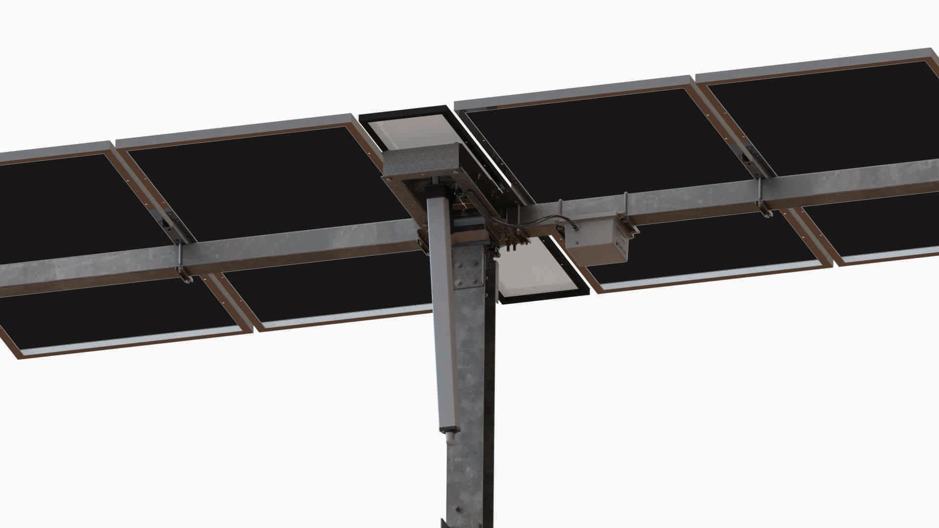
PRE-ASSEMBLED DRIVE SYSTEM
50% FASTER ACTUATOR
Rugged design for 40-year field life in harsh environmental climate: IP66 rated.
SADDLE BRACKET
Allows efficient alignment with row tube.
DRIVE POST
Available as either 8 in. [20.3 cm] wide SuperPost™ or Wide Flange.
OWNER BENEFITS
POWER PRODUCTION
No machines or driveline for industry’s fastest install. Global Innovation Leader for Trackers, Fixed Tilt & BOS
INSTALLER BENEFITS
CONTROLLER
24V battery charged by small solar module drives. 24V actuator motor, Zigbee wireless communication.
SELF-LUBRICATING DRIVE BEARING
Self lubricating open form polymer bearing that improves damping.
2% 200% RESULTS IN HIGHER KWH OUTPUT WITH SPEEDCLAMP™ THAN ANY OTHER TRACKER
INSTALL

OVER 29 GW SOLD
OWNER BENEFITS
UP TO 2% MORE POWER PRODUCTION
Results In higher kWh output.
HIGHER MODULE DENSITY
Increased row spacing means more time facing the sun and less time running from the shade. Adds up to 5% more power production than competitors.
WEATHERSMART™
Proprietary algorithm optimizes tilt angle based on weather data to maximize power production. Adds up to 1.25% additional power production.
LOWEST O&M COST
Lowest grass cutting & module washing cost.
ZERO MAINTENANCE DRIVE SYSTEM
INSTALLER BENEFITS
FASTEST INSTALLING SYSTEM
Advanced design innovations & pre-assembled components.
SPEEDCLAMP™
Mounts modules with no mounting hardware, speeds module installation up to 200%.
PRE-ASSEMBLED DRIVE ARM
Can be lifted by one worker. No machine required. 50% faster than most competing systems.
PE STAMPED DRAWINGS
Design loads according to local building codes: ASCE 7, NBC, Eurocode, AS1170, IS 875.
PROPRIETARY INTEGRATED-HARDWARE™
Proprietary hardware allows for faster structure assembly, module mounting, and reduced O&M cost. Oversized Serrated Flange Nyloc Nut and Oversized Flange Star Bolt with integrated star washer eliminates the need for washers and star washers.
GameChange Solar
HEADQUARTERS
230 East Ave, Suite 100
Norwalk, CT, USA
Phone: +1 (203) 769-3900
Fax: +1 (646) 607-2223
gamechangesolar.com media@gamechangesolar.com
GLOBAL LOCATIONS
El Paso, TX Florence, SC Dublin, Ireland
Madrid, Spain
Wuxi, China Bangalore, India
Dubai, UAE
Buenos Aires, Argentina
Johannesburg, South Africa
Newcastle, Australia
SERVICE SUPERCENTERS
Lakeland, FL, USA
Mesa, AZ, USA
Bogotá, Colombia
Modules Modules Supported
Civil Slope Tolerance (N-S)
Most commercially available modules, including frameless crystalline and thin film
7% standard, can go to 15% special order
Slope Tolerance (E-W) 15%
Tracker follows slope (Y/N) Yes
Structural Drive Type
Posts per MW
Design Wind Load
Snow Load
Design
Install
Electrical
O&M
Santiago, Chile Madrid, Spain
RESEARCH & DEVELOPMENT CENTER
Brimfield, MA, USA
DISCLAIMER:
Robust linear actuator stainless steel & aluminum
350-400/MW for 1 up portrait / 2 up landscape or 250-300/MW for 2 up portrait
105 mph [46.9 m/s](Std) / 130 mph [58.1 m/s](Premium 1) / 150 mph [67 m/s](Premium 2)
5 psf [.24 kPa](Std) / 20 psf [.96 kPa](Premium 1) / 40 psf [1.92 kPa](Premium 2) / 60 psf [2.87 kPa](Premium 3)
Tracking Range (Std) 45°, 52°
Tracking Range (Premium) 60°
Post Sections
Post Size (Interior) & (Exterior)
Motor Foundation
Standard Embedment
Flood Plain Allowance
Module Configuration
Length per Table
Module Attachment
Ground Coverage Ratio
Rows per Drive
Powering System
Ground Clearance To Module
G235 [55 μm] galvanized steel (or HDG option) roll formed standard posts, HDG wide flange option also available
6 x 6 in. [15.24 x 15.24 cm] roll form shape or W6x7, W6x9, W6x12 or W6x15 wide flange
6.5 x 8 in. [16.51 x 20.32 cm] roll form hat or W6x15 or larger wide flange
5 - 7 ft. [1.52 - 2.13 m]
Up to 6 ft. [1.83 m]
1 or 2 up in portrait for crystalline & First Solar Series 6™, 2 up landscape or 1 or 2 up in portrait for Bifacial, 3 to 4 up landscape for First Solar Series 4™
Up to 500 ft. [150 m]
SpeedClamp™ or bolts available for bottom mount frame modules or clamps for glass on glass modules
0.25 to 0.65
1 drive per tracker(table), distributed drive system
Onboard solar module with battery
18 - 48 in. [45.7 - 121.9 cm] typical
Min / Max Ground to Top of Post 3'-8" [1.12 m] typical + 9 in. [22.86 cm] min. adjustment range
Backtracking / Anti-shading
Temperature Range
Electromagnetic Interference
Specialty Tools Required
Max Offload for Deliveries
Tracking Method
String Design
Cable Supports
Linear Actuator Motor
Parasitic Loss
Controller Box
Control System
# of Motors
1000V System or 1500V System
Grounding Method
UL Compliance
Ingress Protection
# Anemometers
Monitoring System
Snow & Flood Sensors
Backup Power
Warranty
Shipping Max load
Shipping Containers or Flatbeds
Yes, although can be turned off as requested (i.e. for FSLR modules)
-20° C (-40° C also available) + 48° C
Compliant with FCC guidelines/ Applicable sections EN 61000
No
As per customer requirement
Time and location based algorithm
Compatible with any string size
Hole punching per customer requirement for nominal cost
24V DC UL Listed
0 amps
Zigbee wireless communications, 24V solar module and battery
Master to Node: Zigbee wireless communications
Master to SCADA/DAS: Modbus TCP communications
20 to 52 / MW depending on module wattage and loading conditions
(35 for typical conditions)
Both
Tracker structure is part of grounding path per UL 2703
UL 2703 / UL 3703
IP66 Actuator [NEMA 4 equivalent]
1 per 6 MW - 10 MW typical
Web portal interface available
Compatible with all standard third party monitoring vendors
Move modules to optimum location for weather events
Solar module and battery providing integrated backup - 3 days
5 year drive & control, 10 year structural standard, 10 /20 also available
International - 18.5 to 22.5 metric tons per container
USA - 45,000 lbs. [20,411 kg] per truckload, 5,000 lbs. [2,267 kg] maximum
bundle size, 2,900 lbs. [1315.4 kg] or other maximum as requested by customers
Flat beds for structure, dry vans for hardware
# Trucks or Containers per MWdc 4 typical for trucks, 5 typical for containers
Commissioning Backfeed required?
No, generator for power as alternative

GENIUS TRACKER






Norwalk, CT, USA
Phone: +1 (203) 769-3900
Fax: +1 (646) 607-2223
gamechangesolar.com media gamechangesolar.com
Dublin, Ireland
Madrid, Spain
Wuxi, China
Bangalore, India
Brimfield, MA, USA
Dubai, UAE
Buenos Aires, Argentina
Johannesburg, South Africa
Newcastle, Australia
Lakeland, FL, USA
Mesa, AZ, USA
Santiago, Chile
Madrid, Spain


I GENERAL
Please carefully follow this manual to learn how to correctly install the GameChange Solar Genius Tracker™ system. The Genius Tracker is engineered and tested to withstand wind and snow loads to specification when installed properly. Failure to precisely follow the install manual may decrease the performance of the Genius Tracker and will void the warranty. It is highly recommended for installation crews including EPC, installer, foundation installer and surveyor to be trained by GameChange Solar personnel, including a complete page turn review of the install manual, construction drawings, and building the golden row.
This is the generic manual and it includes all components utilized in all variations of the Genius Tracker™. Please refer to the Project Construction Drawings and bill of materials for the specific components for your system as some components may not be required. This manual contains dimensions in both Imperial and Metric Units. Should a discrepancy exist, the Imperial Units govern.
The Genius Tracker has a significant capacity to function on sloping ground. However, the Genius Tracker shall not be installed on ground exceeding maximum north-south slopes of 7% (unless specific approval has been obtained from GameChange in which case slopes up to 15% may be permissible) or east-west slope of 15%.
I CRITICAL INFORMATION INDICATOR: This icon indicates critical and important information that MUST be followed for proper installation. Disregarding it may lead to serious injury and/or irreparable damage to equipment, tools, or components, and will compromise the GameChange warranty. Information indicated with this icon must be followed to meet quality requirements.
H CAUTION - Risk of Electric Shock
\ CAUTION - HOT SURFACES: To reduce the risk of burns – Do not touch.
! IMPORTANT NOTE: This icon indicates information that is useful and important for efficient installation of the system or system O&M.
! BEST PRACTICE INDICATOR: This icon indicates information that facilitates the assembly of tracker components.
II SITE SELECTION
• The Genius Tracker system is intended to be installed in an area where public access is restricted by a fence, secured location, etc.
• Proper preparation of surface must be ensured for a well-performing system to be installed.
• Grading of the ground on the installation area is the responsibility of the customer and should be completed properly to enable the slope tolerance for the Genius Tracker system.
General guidelines include:
• Choose a clear area free of shading.
• Suggested minimum ten (10) foot [3.050 m] border surrounding array to edge of property.
III SAFETY PRECAUTIONS AND RESPONSIBILITY OF INSTALLER
I WARNING ELECTRIC SHOCK HAZARD. THE DC CONDUCTORS OF THIS PHOTOVOLTAIC SYSTEM ARE UNGROUNDED AND MAY BE ENERGIZED.
H CAUTION – RISK OF ELECTRIC SHOCK: When the photovoltaic array is exposed to light, it supplies a dc voltage to this equipment. Cover PV Module with opaque material or take other appropriate safety measures before connecting or disconnecting PV Circuits and Power Boxes.
Responsibilities of Installers:
• Follow all instructions in this Install Manual and Project Construction Drawings.
• Installer must provide permanent AC power to Master Controller for commissioning and system operation.
• Installer must provide hardwired Ethernet or fiber optic network connections to all Master Controllers. Depending on the installation type, the network connections may connect to plant SCADA, the GeniusHub onsite operator console, or the internet.
• Use qualified personnel only.
• Use only GameChange parts. Using other parts to complete the installation as substitutes may void the warranty.
• Verify the ground can support the load resulting from the Genius Tracker system.
• Follow all safety procedures as outlined in this Install Manual, both for mechanical and electrical aspects of the solar PV array installation.
• Follow all safety instructions that are required by relevant local, regional and national organizations.
• Store materials in optimal manner to protect components. See Materials, Storage and Warranty section below for more information.
I General Safety Precautions:
• Plan for safe practice during any installation activity with respect to hazards from tripping, falling, lifting, repetitive stress, and any overhead or electrical hazards. Refer to OSHA safety guidelines.
• Metal components often have sharp edges. Handle carefully. Wearing gloves and protective sleeves is good practice.
• This document is not prescriptive regarding safety and does not purport to address all the safety concerns that may arise with its use. Contractors should become familiar with all applicable safety, health and regulatory requirements before beginning work.
H Electrical safety notice – The Genius Tracker™ is a mechanical system with a low voltage power and control system. Mechanical installers and electricians shall coordinate in order to ensure that all personnel are aware of electrical hazards that may occur once modules have been placed on the racking structure. Grounding and Wiring methods shall be done in accordance with NEC ANSI/ NFPA 70 or equivalent local electrical code.
I Field modifications and workarounds – Unauthorized field modification and workarounds of GameChange components or assemblies may affect GameChange warranty coverage. Provide marked up drawings for GameChange’s review, comment and written approval prior to attempting any field modifications. Installers laying out or installing arrays may encounter undocumented or unexpected obstacles requiring a workaround. Since PV arrays are intended to be primarily regular and repeating structures, workarounds should be brought to the attention of GameChange personnel prior to being done. If approved by GameChange in writing, they should be noted on working drawings or in the RFI log.
I All local, regional and national safety requirements should be followed when installing the Genius Tracker system. All equipment/ tools should be properly maintained, calibrated, and inspected prior to use. This installation manual is intended for use by professional installers with a working knowledge of construction principles. If the install manual is not followed completely the warranty may be voided and the solar power system may not operate optimally.
Periodic maintenance of the system should be performed based on information in the O&M Manual. The O&M Manual includes a list of requirements to be verified/performed on an annual basis or following a significant weather event. Failure to follow the O&M instructions will result in sub-optimal, potentially dangerous operation of the system and will void the warranty. Any loose components or fasteners shall be re-tightened in accordance with the Project Construction Drawings. Any components showing signs of damage that compromise safety shall be replaced immediately.
Proper preventative maintenance includes following the practices specified by AAMA 609 & 610-02 – “Cleaning and Maintenance for Architecturally Finished Aluminum” (www.aamanet.org) and equivalent standards for galvanized steel products. All installations in corrosive atmospheric conditions or areas of periodic submersion or ponding, or where components were subject to any ponding or moisture while still bundled prior to installation at the site, are excluded from the Warranties, at the sole discretion of GameChange. Notify GameChange immediately upon discovery of any potential or suspect defect at time of discovery. Any alteration, modification or repair of the system without written authorization from GameChange Solar will void warranty. Any use of the system in a manner or for a purpose other than that specified by GameChange, or installed in any manner not specified by, or recommended against in, the installation manual provided by GameChange will void warranty.
Snow/Flood Sensors must be properly maintained and calibrated. Failure to do so could cause false positives or negatives which could adversely affect production and void the warranty. It is the responsibility of the Purchaser and/or subsequent Warranty holder that snow accumulations of 6 inches or more is removed from the solar modules before the System resumes tracking. In addition, snow must be cleared from the area under tracker tables to prevent damage from tracker tables rotating into snow banks.
See the Project Construction Drawings for post-to-post spans as well as maximum cantilever lengths for Beams and Cantilevers. Installation of components outside of tolerances shown in Project Construction Drawings may result in structural failure and will lead to voiding of product warranty.
IV MATERIALS, STORAGE AND WARRANTY
All materials are made from non-corrosive materials: galvanized steel, Magni coated steel, stainless steel, aluminum, polypropylene or polyethylene.
Galvanization is the application of zinc to steel to prevent rust. When the galvanized component is installed and air circulates over the zinc, a chemical reaction takes place which forms a protective coating of zinc carbonate. This ensures the zinc will properly protect the steel from corrosion.
I Storage of recently galvanized components left for a significant amount of time in a tightly bundled state in moist environments can cause a condition where the parts have water on their surface, preventing air flow across the surface. This inhibits the zinc from forming a protective zinc carbonate layer, which in turn may result in a condition called storage stain. The resulting zinc compound can balloon in volume and have the appearance of white powder. This condition can be minor and result in only a nominal loss of zinc coating thickness. However, if the parts are left for several weeks in a tightly bundled state this condition can result in more severe damage to the zinc coating, which could lead to premature corrosion damage, including but not limited to red rust spots. Leaving the components in this state for an extended period of time can result in loss of mass of the base metal and reduce the life span of the structural component.
I Unbundle loads and install parts within three weeks of delivery, so air is able to flow around parts and thus prevent storage stain formation. Prior to unbundling, place blocking under one side of loads so that parts are at a slope of at least 8 degrees. This will allow rain water to run off and not pool on components. In order to best maintain the longest life possible for the protective zinc coating under the warranty, it is important to monitor for any severe storage stain development and if a severe storage stain condition appears to take proper maintenance steps to remediate it.
I Bundled materials should not be stored directly on the ground. They need to be elevated above ground level using dunnage. Bundles should be stacked to a maximum of 2 levels, with dunnage between each level.
! Actuators, Controllers, Charging Module, and sensors are sensitive electronic devices and should be handled with extreme care. Disregarding this notice may result in damage to this equipment and will void warranty.
! Actuators, Controllers, Charging Module, and sensors should be stored inside a job site connex whenever possible. If this is not possible they should be single stacked in a dry, well drained area or laydown yard, elevated off ground with weatherproof tarp loosely covering the equipment to keep rain, snow and dew off the equipment, and allowing moisture to evaporate and not condense on the equipment.
V TOOLS REQUIRED
Tool requirements:
• String line, laser level or transit
• 48 inch [1219 mm] long level
• 30 and 100 foot [9 m and 30 m] tape measure
• Barrel laser suggested for aligning bearings (Recommended but not required)
• Drill with interchangeable socket adapters
• 11/32” Drill Bit to pre-drill Row Tube for TEK screw (optional)
• 7/32” Drill Bit to pre-drill Drive Housing for TEK screw
• Rated sockets and wrenches, both standard and deep, in the following sizes:
- 7/16 inch (for 1/4-inch hex bolts and nuts)
- 9/16 (for 3/8-inch hex bolts and nuts)
- 3/4 (for 1/2-inch hex bolts and nuts)
- 1 1/8 (for 3/4-inch hex bolts and nuts)
- 1 11/16 (for 1 1/8-inch hex bolts and nuts)
- 1 3/16 (for M20 bolts and nuts)
• Open end crowfoot wrench for 1/2 inch serrated flange nuts
• Torque wrench(s) capable of applying 6 ft. lbs. [8.2 N-m] to 140 ft. lbs. [189.8 N-m]
• Outdoor rated gray paint approved for plastic such as Rustoleum Industrial Enamel
• GameChange Solar System components (see page 4)
• Inclinometer with digital degree read out
• GameChange Solar Project Construction Drawings
• Cold galvanizing paint with a dry film zinc content of at least 92% (if required)
• Torque limited screwdriver
• Smart Phone or cell-enabled Tablet with GameChange Solar Web App and login
• Hellermann Tyton Aerial Support Tie (Part PA66HIRHSUV) or equivalent UV-resistant cable ties.
It is the responsibility of the installer to install fasteners within the finishing torque ranges shown in the project construction documents. The method in which this is achieved, including but not limited to torque wrenches or blue tooth enabled drill guns, with or without torque marks, is at the sole discretion of the contractor.
! Recommended practice is to run the nut up the bolt just enough to engage the bolt head and nut with the components they are connecting. A torque wrench should be used to finish the connection to the specified torque.
VI SYSTEM COMPONENTS
Cold Formed Center Post & Bearing Standard Post & Bearing
Center Post (GC61HGT)

Wide
Preassembled Center Bearing (GC6601S-7.22-GC4367NL-LCH-6.75-P) or (GC5601S-7.22-GC5367NL-LCH-6.75-P)
Center Saddle Bracket (GC1610 - 3.6 - 61HGT)


Flange
Wide Flange Center Post (GC461C) or (GC561C)

Row Tube
Row Tube (GC365) or (GC565)

Center
Post Bracket (GC1611)


Bottom Bracket (GC1612)


Post & Bearing (if provided)
Preassembled Center Bearing (GC6601S-7.22-GC4367NL-LCH-6.75-P) or (GC6801S-7.22-GC4367NL-LCH-P) or (GC5601S-7.22-GC5367NL-LCH-6.75-P)

Wide Flange Center Saddle Bracket (GC2610) or (GC5811)

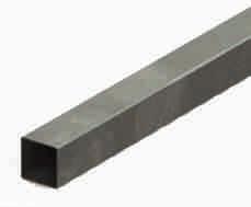
Preassembled Squeeze Splice (GC1355F-6.90-8) or (GC1455-8)


Row Tube Cap (GC364) or (GC564-I)
Bonding (if available, otherwise use NEC rated braided jumpers)
Wide Flange Standard Post (GC461T-W6) or (GC561T-W8)
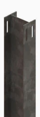
Standard Saddle Bracket (GC6610) or (GC5811)


Z Post Alternate Standard Post (GC561Z) (Alternate)

Standard Saddle Bracket Long (GC6610L)


Standard Saddle Bracket Extra Heavy (GC6610EH) or (GC5811H)

Preassembled Single Piece Bearing (GC6601SB-GC6367SR-P) or (GC6801SB-GC6367SR-P) or (GC5601SB-GC5367SR-P )
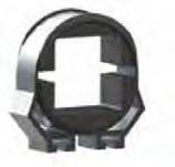
Purlin & Purlin Mounting
Preassembled Purlin (GC4903TWT) or (GC5903TWT)
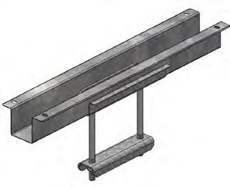
Node Controller (GC2012)
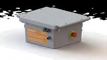
Purlin Strip (GC915)
Bridge Plate (GC914) Alternate
Actuator & Controller Master Unit
Stow Arm Components
Driving Arm Assembly System (GC4600FH) or (GC5605FH) (Delivered Fully Preassembled)
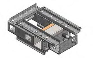
Extended Driving Arm Assembly System (GC4600FEH) (Delivered Fully Preassembled)

Charging Module (GC4291FE)

Actuator Assembly (GC2008S) Alternate (GC2005)
Charging Module Washer (GC4295)

Square U-Bolt (GC1325)

Purlin Channel (GC4378BU) or (GC5978BU)

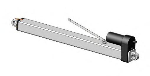

Damper Arm Assembly (GC4281) or (GC5281) Tracking Damper (GC4567D)
Damper Bottom Assembly (GC4890W) alternate (GC5890W)
Limiting Damper (GC4467D)

(MC110)


Support (GC2110) Master Pole U-Bolt (GC2098) Snow/Flood Sensor (if required)


Pole (GC2099)


(GC21094) Pole Angle Master (GC2106MA)



NOTE: See Project Construction Drawings and BOM to confirm which components are being delivered preassembled.
Preassembled Components
(Assemblies for 4” tube shown, assemblies for 5” row tube also available.)
Squeeze Splice
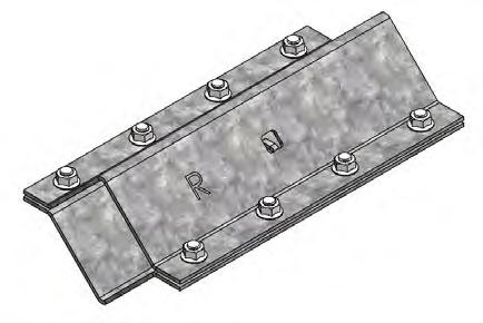

Components and Sub-Assemblies Components and Sub-Assemblies
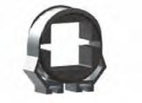

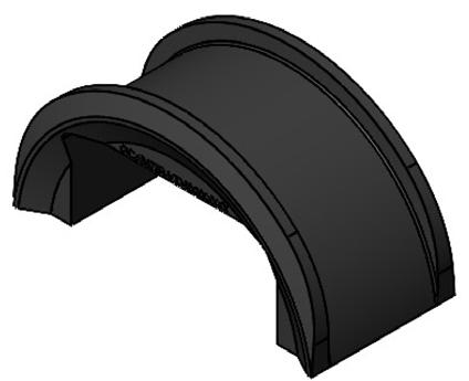
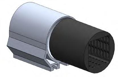
Components and Sub-Assemblies


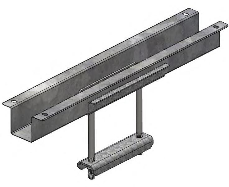
Components and Sub-Assemblies
See “Step 10: Purlin Installation” on page 40 for more details.
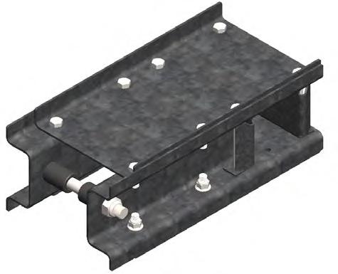



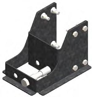
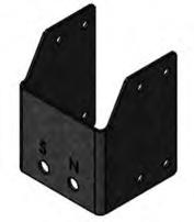
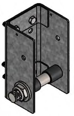
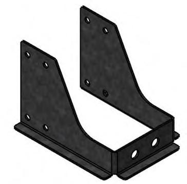
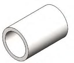
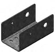
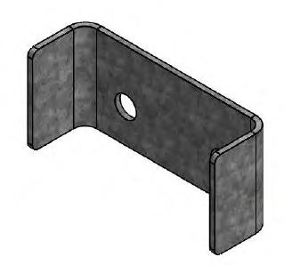
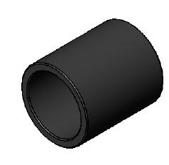
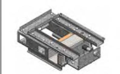


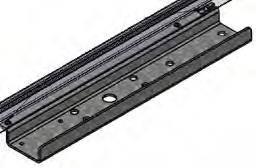

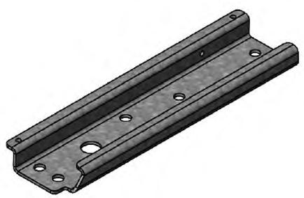
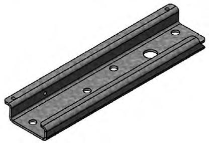
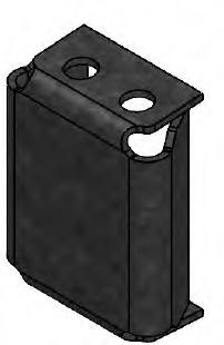
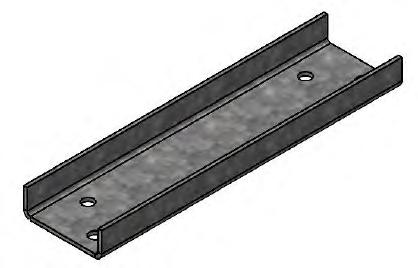
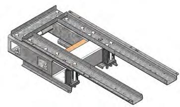


Associated Hardware
Note for all hardware:
• Grade 8 hardware cannot be retorqued.
• If the bolt flange is not serrated, and the nut is serrated, it is preferable to apply torque to the bolt head.
! Use only Imperial sockets sizes with Imperial size hardware to prevent damage to the anti-corrosion coating.
For installing each Saddle Bracket onto Center Post:
• ½-13 flange hex bolts – magnicoat (8)
• ½-13 serrated thick flange hex nut, (.54” tall) - magnicoat (8)
Torque: 90-100 ft-lbs [122-135.6 N-m]
For installing each Standard Saddle Bracket onto Standard Wide Flange:
• ½-13 flange hex bolts – magnicoat (4)
• ½-13 serrated thick flange hex nut, (.54” tall) - magnicoat (4)
Torque: 90-100 ft-lbs [122-135.6 N-m]
For installing each Center Bearing Collar onto Saddle Bracket:
• ½-13 x 1 ¼ inch carriage bolts – magnicoat (6)
• ½-13 serrated flange nuts (grade 8 or grade 5 nuts may be provided; consult Project Construction Drawing) – magnicoat (6)
• ¼-14 x ¾ inch serrated head TEK screws – magnicoat (or SS) (2 or 4)1
Torque: 72-75 ft-lbs [97.6-101.7 N-m]
For installing each Single Piece Bearing onto Saddle Bracket:
• ½-13 x 1 ¼ inch carriage bolts – magnicoat (2 or 4)
• ½-13 serrated flange nuts – magnicoat (2 or 4)
Torque: 72-75 ft-lbs [97.6-101.7 N-m]
For assembling Row Tube with Squeeze Splices:
• ½-13 x 1 ¼ inch hex bolts – magnicoat (8)
• ½-13 serrated flange nuts – magnicoat (8) or alternate:
• ¾-10 x 1 ½ inch hex bolts – magnicoat (8)
• ¾-10 serrated flange nuts - magnicoat (8)
torque: 75-80 ft-lbs [101.7-108.5 N-m]
For installing Driving Arm assembly onto Row Tube:
• ½-13 x 6 inch bolts – magnicoat(8)
• ½-13 serrated flange nuts magnicoat (8)
• ⅜-12 x ¾ inch (1 inch and 1 ¼ inch long also acceptable) serrated head TEK screws – magnicoat (or SS) (2)1
Torque: 60-70 ft-lbs [81.3-94.9 N-m]
For installing each Bottom Bracket onto Center Post:
• ½-13 x 1 ¼ inch hex bolts – magnicoat (6)
• ½-13 serrated flange nuts – magnicoat (6)
Torque: 90-100 ft-lbs [122-135.6 N-m]
For installing Actuator onto Driving Arm Assembly:
• 9 inch hex bolt – magnicoat (1)
• 1 ⅛-7 Nyloc nuts – magnicoat (1)
Torque: 5 ft-lbs [6.8 N-m] or torque until flush
1 Torque to flush
For installing Actuator onto Bottom Bracket:
• 7 inch hex bolt – magnicoat (1)
• 1 ⅛-7 Nyloc nuts – magnicoat (1)
Torque: 5 ft-lbs [6.8 N-m] or torque until flush
For installing Controller with Brackets onto Row Tubes:
• 3/8-16 U Bolt - magnicoat [1]
• 3/8-16 serrated flange nut for U bolt – magnicoat (2)
Torque: 9-10ft-lbs (108-120 in lbs) [12.2-13.5 N-m]
For Installing Damper Arm onto Row Tube
• ½-13 x 6 inch bolts - magnicoat [8]
• ½-13 serrated flange nuts - magnicoat [8]
• ⅜-12 serrated head TEK screw - magnicoat [1]2
Torque: 60-70 ft-lbs [81.3-94.9 N-m]
For installing Damper Bottom onto Damper Post:
• ½-13 x 1 ¼ inch hex bolts - magnicoat [8]
• ½-13 serrated flange nuts - magnicoat [8]
Torque: 90-100 ft-lbs [122-135.6 N-m]
For installing Damper onto Damper Arm:
• M20-2.5 x 170 mm hex bolt - magnicoat (1)
• M20-2.5 Nyloc nut (1)
Torque: 5 ft-lbs [6.8 N-m] or torque until flush
For installing Damper onto Damper Bottom Bracket:
• M20-2.5 x 150 mm hex bolt - magnicoat (1)
• M20-2.5 Nyloc nut (1)
Torque: 5 ft-lbs [6.8 N-m] or torque until flush
For installing Braided Jumper Hardware:
• ¼-20 x ¾ inch hex bolt and ⅜-16 x 1 inch hex bolt – SS (or magnicoat) (up to 2)
• ¼-20 and ⅜-16 serrated flange nut - SS (or magnicoat) (up to 2)
Torque: 10 ft lbs [13.5 N-m]
For installing Purlins with Brackets onto Row Tubes:
• BSQ36 Thru Bolt (2)
• ⅜-16 Nyloc nuts (2)
Torque for purlin varies (see project construction drawings)
For installing Modules and Charging Module onto Purlins:
• ¼-20 x ¾ inch hex bolt – SS (or magnicoat) (quantity varies)
• ¼-20 serrated flange nut - SS (or magnicoat) (quantity varies)
Torque: 9.5-10 ft lbs (114-120 in lbs) [12.9-13.5 N-m]2
For installing Master Unit, Anemometer and related brackets together and onto Pole:
• 1/4-20 x 3/4 inch hex bolt (6) and 3/8-16 x 1 inch long (2) hex bolt – SS (or magnicoat)
• 1/4-20 (6) and 3/8-16 (14) serrated flange nut - SS (or magnicoat)
• 3/8-16 serrated flange nut for U bolt – magnicoat (2)
Torque: 9.5-10 ft lbs (114-120 in lbs)[12.9-13.5 N-m]
2 Torque listed is for magnicoat. See torque table for Stainless Steel hardware torque value
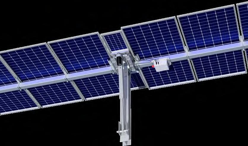
The GameChange Solar Genius Tracker™ is a simple, easily installed ground-based solar mounting system. Components are made from galvanized and stainless steel. Slopes up to 7% north to south and 15% east to west are allowable under all normal conditions. For installation requiring slopes in excess of the 7% N-S and 15% E-W, consult with GameChange Solar Engineering.
1 CONTROLLER
24V battery charged by small solar module drives 24V actuator motor, wireless mesh communication
2 PREASSEMBLED DRIVE SYSTEM
50% FASTER
than typical competitor drive systems. One worker lift, no machine required
VIII TOP TIPS
3 ACTUATOR rugged design for 40 year field life in harsh environmental climate: IP66 rated
4 SELF-LUBRICATING DRIVE BEARING
5 SADDLE BRACKET allows auto-alignment with tube
6 CENTER POST available as either GameChange 8” [20.32 cm] wide SuperPost or Wide Flange
• Ensure Center Post installed perpendicular to Row Tube and azimuthally within tolerance.
• Controllers, sensors, and actuators are sensitive electronic devices and must be handled with care.
• Do not run tables prior to commissioning without GCS Rotator Harness.
• Do not spin out Actuator tube.
• Storage of components in a damp or wet environment can lead to white rust on galvanized parts as well as other damage on other protective coatings which can lead to accelerated corrosion of components, and void the warranty. (See page 3 for further details).
Step 1: Placement of the Posts – Post Installation for Driven Posts
1.1 Locate, measure and lay out the array according to the GameChange Project Construction Drawings. Proper installation will result in top of post to top of post distances matching the layout. In order to achieve this, two factors must be considered and properly compensated for:
1.1.1 Sloping Ground (ground slopes over 3%) will result in distance between posts growing as compared to the required distance. Thus, the measurement shall be taken along the slope of the table and place rooster tails (post driving flags) at proper distance along that slope, NOT AT PLAN VIEW LOCATIONS.
1.1.2 Center Post shall be perpendicular to the Row Tube while Standard Posts shall be plumb. This will result in the top of the Center Post moving downhill relative to the bottom of the Center Post. See chart below for top of Center Post offset due to Row Tube slopes at various top of pile elevations.
1.2 The Genius Tracker has a significant capacity to function on sloping ground. However the system shall not be installed on ground exceeding maximum north-south slopes of 7% (up to 15% available upon special request from GameChange) or east-west of 15%.

1.3 For cold formed center posts, mark out center posts first, then mark out all posts running north to south along centerline.
1.3.1 Mark post locations with locator flags according to array plan - Make sure distance between foundations is measured from center of post to center of next post along each table plane (not from plan view, see specified distance in figure on next page). Otherwise foundation locations will creep if there is rolling terrain, since plan view does not factor in vertical component of distance. This could make N-S Row Tube attachment more difficult.
1.3.2 Width and depth of center post does not match standard post. If placing rooster tail (post driving flags) at corner of posts, make sure to account for shape differences. See Project Construction Drawings.
1.4 Key the post shape into the driver head as shown to the right. This will help prevent twist and mushrooming of post top.
! Suggested Means & Methods
1.1 Prepare Post elevations using stakes

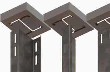

1.1.1 Stakes shall be used to mark the ends of tables. Wherever one table end meets an adjacent table end, a single stake is recommended (instead of two) to mark the location where they come together.
1.1.2 The tops of stakes shall be initially set at 1 ft [0.305 m] (or a consistent height relative to the middle of the adjustable range of the Posts).
1.1.3 Use aircraft cables to go north-south from one stake to the next. More stakes may be added in between to locate the Center Posts. Based on variation from 1 ft [0.305 m] height, verify that the Center Post embedment depths would fall within the acceptable range. If outside of the range, adjust the stakes on either side of the table to get an appropriate elevation for the Center Post. Be sure that Standard Posts also fall within allowable elevation range, which is typically greater than the Center Post range.

1.5 Tops of the posts of each table shall be on the same plane. Each table may be at various tilts to follow the topography, however, the tops of all posts of individual tables must be at a consistent slopes (with a tolerance of ± 1 inch [25 mm]) for the entire length of the table.
1.5.1 GameChange Post lengths are typically designed with 9 inches [228 mm] of adjustment to the minimum embedment depth to aid in getting to the +1/-0 inch [+25 mm/-0 mm] (Center Post) or ± 1 inch [25 mm] (Standard Post) tolerance mentioned below. Minimum embedment depth and adjustment range is identified in the site specific Project Construction Drawings and refers to the total length of the Post minus the exposed length.
1.5.1.1 In case of severe undulations of the ground made known prior to delivery, longer types of posts or post extenders may be provided as appropriate to support the system over the severe undulations
1.5.1.2 GameChange provides a range of embedment depths to allow for this.
1.5.1.3 Note that embedment depth will vary. Be careful to always meet minimum embedment depth as shown on Project Construction Drawings.
1.5.2 Please review site-specific Project Construction Drawings including assembly print for details
1.5.3 When post driving, overdrive posts so that all of the adjustment zone is in the ground at high points and drive only to minimum embedment depth so that all of the adjustment zone is above ground at low points. Drive posts between high and low points in topography so that adjustment zone is proportionally embedded or above ground.
1.5.4 Unless otherwise instructed by project ownership, posts shall be installed to provide 12” [300mm] of freeboard to flood waters per ASCE24.
Center Post Embedment Limits
Standard Post Embedment Limits

1.5.5 Top of posts running north to south can be at a maximum slope of 7% (up to 15% available upon special request from GameChange) so long as the slope is constant. Make sure to follow the laser or transit along the length of the table and at consistent points on the posts per table while adhering to tolerance requirements.
1.5.6 In the north-south plane, Center Posts shall be within ± 1° perpendicularity to Row Tube. Standard Posts shall always be plumb to within ± 3°.

Specified Distance
Proper Height
Proper Height Stakes
Center Posts Perpendicular to Row Tubes
Standard Posts Plumb
1.5.7 In the east-west plane, Center Posts shall be plumb within ± 1° and Standard Posts shall be plumb within ± 3° It is essential that Center Post is within perpendicularity and azimuthal tolerance to Row Tube or else system will not function properly and warranty will be void. The following example shows typical relations between max and min allowable Center Post and Standard Post embedment depths.
± 2” Tolerance for Adjacent Tables
Longer Posts for Extreme Undulations

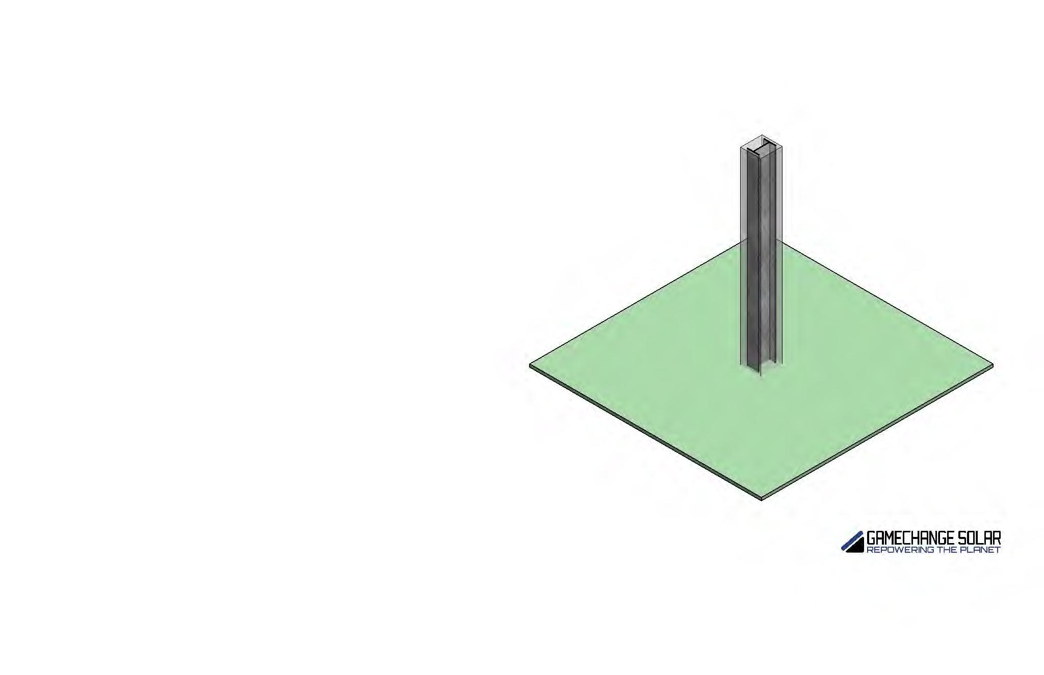
± 3-degrees Plumbness for Standard Posts
Post Installation Tolerances
Center Post shall be within ± 1-degrees Perpendicularity to Row Tube

Center Post
Top of Post Tolerances (MeasuredPerpendicularitytoRowTubeN-S withsquarefromRowTube)
1.5.8 Hat Channel Center Posts are not centered to the Standard Posts in the East-West direction. The eastern wall of the Hat Channel Center Post shall be aligned to the eastern wall of the Standard Posts. Once Post Bracket, Saddle Bracket, and Drive Housing are installed, the Drive Housing and Standard Post Bearing Collars will come into alignment. This DOES NOT APPLY for Wide Flange Center Posts. Wide Flange Center Posts are centered with the Standard Posts.
1.5.9 Make sure the top of the posts from one row to the next row going east-west are at heights appropriate to the row spacing. Any difference in height to row spacing ratio could potentially result in shading of modules which could cause the system to perform sub-optimally when coupled with an inadequate spacing between rows.
1.5.9.1 In some sites the system may be predesigned with an east-west slope for the entire site. Genius Tracker can accommodate 15% east to west slope for a site. Higher slopes may be possible upon special request and confirmation from GameChange.
Note: Topography files must be provided to GameChange Engineering if East-West slope is to be accounted for in controller programming.
1.6 Center Post (GC61HGT) Installation
1.6.1 Make sure the Center Posts are installed with the open side facing towards the eastward azimuth of the array.
GC61HGT (COLD FORMED)
GC461C (WIDE FLANGE) EAST
! For Primary Center Posts, align Eastern walls of the Center Post and Standard Posts
! For Alternate Wide Flange Center Posts, align centers of the Wide Flange Center Post and Standard Posts
1.6.2 Make sure Center Posts are squared to within azimuthal tolerance to the array of ± 2° . This is very important because the Center Posts mount the drive system for the Genius Tracker, and having precise alignment ensures the drive system will function properly.
1.6.3 Vertical tolerance for the Center Posts -0/+1 inch [-0 m/+25 mm] of the plane of post tops of table. Make sure that Center Posts are installed with height above ground as per the assembly drawing provided by GameChange. This is very important because if not installed correctly the Actuator will get too close to the ground during operation.
I Do not “bump” posts to meet tolerances.
1.6.4 Make sure Standard Posts on either side of Center Posts (for the north-south row) are installed at specified distances (as measured at top of post):
1.6.4.1 North-South ± 1 1/2 inch [± 38 mm]
1.6.4.2 East-West ± 3/4 inch [± 19 mm]
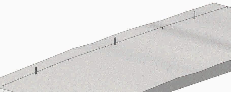
1.7 Standard Post (GC461T) Installation
1.7.1 Make sure for all Standard Posts (GC461T) the open sides face North and South.
GC461T
North South
1.7.2 Make sure for all Z Posts (GC561Z) the open sides face North and South.
GC561Z North Version South Version
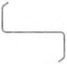
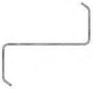
1.7.3 Make sure Standard Posts are squared to within azimuthal tolerance to the array of ± 4°
1.7.4 Vertical tolerance for the Standard Posts ± 2 inch [50 mm] for the plane of post tops of table.
I Do not pull posts up to reach required tolerance.
1.7.5 Make sure next Standard Posts (for the north-south row) are installed at specified distances (as measured at top of post relative to marked location on ground, after factoring in out-of-plumbness):
1.7.5.1 North-South ± 1 1/2 inch [38 mm]
1.7.5.2 East-West ± 3/4 inch [19 mm]
I Do not “bump” posts (laterally move posts with equipment) to reach required tolerance.

1.7.6 Following the above installation steps are important to keep the ends of the tubes in between adjacent tables as close to each other as possible. The allowable vertical (up and down) tolerance is ± 2” [50 mm] between end of one the adjacent table (see “Adjacent Table Spacing” on page 30).


1.7.7 For all aforementioned Post installation steps, be sure to follow embedment depth limitations as shown on the Project Construction Drawings.
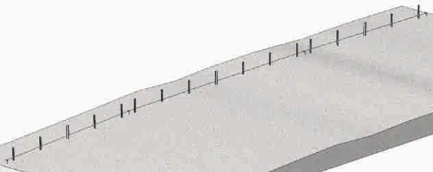

1.8 The minimum horizontal clearance around the post to trenches or other ground disturbances shall be 5 times the post diameter. If this cannot be achieved, contact GameChange’s Geotechnical Engineering Team.
Step 1.1: Placement of the Posts – Refusal Instructions
Step 1.1.1: RFI and General Guidance
• GameChange Solar (GCS) defines refusal when one of the two following conditions is met.
º The drive time rate exceeds 120 s/ft (394s/m)
º The drive rate exceeds 10 blows per inch (4 blows per cm)
º There is visible damage/deformation of the pile
• Refusal data and proof test data must be submitted in an Excel format approved by GameChange to expedite our review. An Excel file for data entry can be provided upon request.
• Pictures or scans of handwritten data sheets will not be reviewed.
• Upon written confirmation from GameChange, the proof testing frequency may be reduced to testing the greater of 5 or 5% of refused posts per array or inverter block. This rule will apply to different remediation options within the same defined area. For example, if 5 posts are remediated with Option 1 and an additional 5 posts are remediated with Option 2 within the same inverter block, all 10 posts would require a proof test. Refer to the “process flow” section for guidance on selecting proof test locations.
• If the minimum refusal depth for Option 1 is greater than 5’-6” (1.67 m) and the proof test loads appear higher than typical wind loading, that means this site is subject to swelling soils, frost heave, or potential scour depths of greater than 1 foot (0.3 m).
• If it becomes clear that certain areas are experiencing high rates of refusal with direct drive these options can be used preemptively but will still be subject to the proof test requirements.
• All refused Center Posts must be remediated with a Drill and Grouted Pier. If the post cannot be removed, a concrete collar/ spread footing can be utilized.
Step 1.1.2: Proof Test Procedure
1.1.2.1 Do not disturb driven posts for a least three days after installation. This will increase the pull-out resistance and any work performed without a waiting period may result in weaker pull-out resistance on the production posts. Proof testing cannot be performed if the ground is frozen.
1.1.2.2 Apply vertical loads concentric to the post so that no eccentricity is created by the load.
1.1.2.3 Loads shall be applied by smooth operation of hydraulic equipment such as a telehandler with precision hydraulic control, a hydraulic jack or a chain fall (chain hoist) so that applied load levels are within 2-3% of the target load level.
1.1.2.4 The height of the applied load shall be at the anticipated final top of pile elevation.
1.1.2.5 Loads shall be measured by a calibrated dynamometer (load cell).
1.1.2.6 Displacements shall be measured by a calibrated micrometer or similar equipment and it must be capable of measuring a minimum of 50 mm of displacement. For the lateral test, the micrometer should be set on the pile as close to existing grade as possible. It should be no higher than 6 inches (152.4 mm) above grade. It is not permissible to measure displacement visually using a string line, tape measure, or ruler. Equipment for measuring vertical and lateral displacement shall be supported by a steel reference beam. The steel reference beam shall be supported on either end by wood blocking or similar. The supports for the reference beam shall not be closer than 5 feet (1.52 m) from the test post.
1.1.2.7 Perform the uplift test first and proceed to the lateral test if that passes.
1.1.2.8 Once the target load level has been reached, hold the load for a time interval of no less than 2 minutes. If the post moves such that the load drops by more than 10% apply more load to keep the load constant. Record the displacement of the post at the end of 2 minutes.
1.1.2.9 Proof test loads and passing deflection criteria are summarized in the table below. See Project Construction Drawings for proof test loads.
Load Testing Specifications
Step
1.1.3.1 Provide GameChange with refused locations in approved excel format which should include pile ID, drive time, refusal depth and any other applicable notes.
1.1.3.2 Determine what quantity of those refusals are eligible for Option 1. GameChange will provide guidance on which piles to test based on the 5 or 5% rule per inverter block. Shallower refusals and geographically dispersed test locations should be a priority. If all designated posts within each block/array pass the proof test, “Cut and Punch” can be utilized on the other affected posts fitting all required criteria for Option 1.
1.1.3.3 If any of the designated posts for Option 1 proof testing fails, expand the testing area from those points to the nearest 4 refused posts in each direction. Repeat that process until no failures are observed. Any posts that failed need to be remediated with one of the other alternative options.
1.1.3.4 For posts that don’t meet the minimum refusal depth shown in the Refusal Instructions sheet of the Project Construction Drawings, contact GameChange Solar Engineering for guidance on which remediation option to follow based on the following considerations.
1.1.3.4.1 Can the piles be removed without damage?
1.1.3.4.2 If not, the only available option is a concrete collar or spread footing.
1.1.3.4.3 If they can, a decision needs to be made on which alternative option is preferred.
1.1.3.5 Once a preferred remediation plan is established for posts that did not reach the minimum refusal depth, proceed with the instructions as defined for that option.
1.1.3.6 If there are still issues with certain posts after following the above workflow, a drill and grouted pier must be utilized as defined in Option 3.
Step 1.1.4: Remediating Refused Posts
Remediate refused post per one of the following options:
Option 1: Cut and Punch (Standard Interior and Perimeter)
1.1.4.1 The standard minimum refusal depth for this option is X’-X”. If the post refuses at an embedment depth shallower than this, the post needs to be removed and one of the other refusal options must be utilized.
1.1.4.2 If the minimum refusal depth is achieved, follow the proof test guidance, and submit the results to GameChange for approval. As noted above, this data must be submitted in an approved format. Once it’s verified that the proof tests passed, the top of the posts may be cut to the appropriate elevation and holes for the saddle bracket field drilled. If it is a Damper post, holes for the bottom bracket must also be punched. Coat field drilled holes with cold galvanizing paint that is at least 92% zinc. GCS field oversite of this process may be provided upon request.
1.1.4.3 If post does not pass proof test, it must be removed and remediated with one of the other refusal options.
1.1.4.4 If the post refuses shallow of the minimum embedment depth and is unable to be removed, the spread footing option may be utilized by excavating around the base of the post. See Option 4.
Option 2: Pilot Hole (40 to 60% of pile diameter) - Loose Backfill
1.1.4.1 Onsite borrow material and drill cuttings may be used if it is non-plastic (less than 50% passing the no. 200 sieve). If onsite material does not meet these requirements, graded backfill material must be locally sourced. Submit an RFI to GCS to confirm backfill requirements.
1.1.4.2 Reference the recommended Maximum Pre-Drill Diameters table on page S460 to determine the maximum pre-drill diameter per post section type.
1.1.4.3 Pre-drill the hole with a DTH hammer, or equivalent, to the maximum embedment depth shown on the pile elevation drawings.
1.1.4.4 Place the approved backfill material in the hole until it is mounded above grade. Add 2 to 5 gallons (7.57 to 18.92 liters) of water to the top of the hole to aid consolidation. Add additional material as necessary after water is added so that the backfill material is mounded above the hole.
Diameters (Imperial
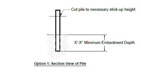

1.1.4.5 Proceed with post installation, record drive times and embedment depth.
1.1.4.6 Follow the proof test guidance and submit the results to GameChange for approval. As noted above, this data must be submitted in an approved Excel format.
1.1.4.7 If the post still refuses but is deeper than the minimum refusal depth, proceed with proof testing and cutting/punching the post if it passes the proof test.
Option 3: Drill and Grouted Pier
1.1.4.1 Concrete should have a minimum 4,000 psi (27.5 MPa) compressive strength at 28 days and a maximum aggregate size of 3/8” (9.5 mm). See “Concrete Requirements” on page 23 for additional concrete specifications. Submit the mix design to GameChange Solar for approval prior to install. If grout is used, grout shall be non-shrink.
1.1.4.2 Concrete materials and installation shall be in general accordance with ACI 318. Most importantly, the concrete should be vibrated during placement to ensure proper settlement. Ensure the vibrator does not hit the post.
1.1.4.3 Drill hole to target embedment depth using a 12-inch (30.5 cm) drill bit.
1.1.4.4 Post should be placed in the hole prior to, or immediately after pouring the concrete.
1.1.4.5 Before the concrete starts to set, the post must be held in place using form work. Contractor is responsible for those means and methods based on equipment availability. Ensure the post is within required tolerances
1.1.4.6 Once the concrete sets, remove all form work. This should be a minimum of 24 hours.
1.1.4.7 Proof testing is not required for this option.
1.1.4.8 Contractor shall ensure concrete placed onsite matches specifications of the approved mix design.
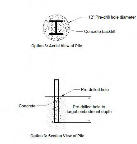

Option 4: Spread Footing or Concrete Collar
1.1.4.1 For Post refusals shallower than the minimum refusal depth that can not be removed, this option must be utilized. GameChange will provide the site specific design upon request.
1.1.4.2 For Post refusals shallower than the minimum refusal depth but can be removed, this option can still be utilized. GameChange will provide the site specific design upon request.
1.1.4.3 This will involve excavating around the base of the post and backfilling with high strength concrete. GameChange will provide the necessary concrete specifications and dimensions in an RFI response.
Step 1.1.5: Mushrooming and other Post Deformation Due to Refusal
Deformation at the top of the posts rarely occurs and typically occurs when posts are driven into rock. This is minor and can easily be remedied. Post deformations could cause problems for the installation of the Saddle Bracket. If any deformation at the top of the posts occurs during installation:
1.1.5.1 If mushrooming is locally isolated above any slots or features and within 1/8 inch [3 mm] of the original drawing dimension (4-15/16”) [125 mm], use a hammer (or equivalent equipment) to reshape the top end of the Post back to within 1/16 inch [1.5 mm] of the original drawing dimension.
1.1.5.2 Place 2-inch [50 mm] thick rubber/wooden block on top of Post to reduce impact and restart post-driving the Post.
1.1.5.3 If posts are deformed more than 1/8 inch [3 mm], then consult with GameChange regarding re-use.
1.1.5.4 Wirebrush the deformed end of the Post and re-coat with 92%+ zinc rich cold galvanizing paint.
Step
1.1.6: Concrete requirements
Concrete for drill and grouted piers, concrete collars and spread footings and for shall have the following properties:
1.1.6.1 Concrete shall be normal weight concrete containing Portland cement and normal weight aggregate conforming to the appropriate ACI standards or similar.
1.1.6.2 Concrete shall have a minimum compressive strength of 4,000 psi [27.5 MPa] at 28 days.
1.1.6.3 Concrete shall have a five inch slump or less.
1.1.6.4 Admixtures may be added but shall not contain chlorides or calcium chlorides.
1.1.6.5 Except as specified below for severe weather conditions, concrete air entrainment and water to cement ratio may vary but shall meet concrete provider’s specifications so that the concrete meets the requirements above. Concrete shall be mixed on or off site per concrete provider’s specifications.
1.1.6.6 Class V cement shall be used for concrete in contact with soil with a sulfate content of 1,500 ppm or greater.
1.1.6.7 For concrete piers aggregate size shall be 3/8” (9.5 mm) or smaller. For concrete collars and spread footings aggregate size may be up to 3/4" (19 mm).
1.1.6.8 For hot weather concreting:
1.1.6.8.1 Temperature of concrete shall be measured for all days concrete is placed when air temperature is over 80 °F (26 °C). Prevent concrete temperature from exceeding 95 °F (35 °C) by placing white poly plastic cover over concrete surface to prevent direct sunlight exposure, chill concrete mixing water, and/or other approved industry standards.
1.1.6.9 For cold weather concreting:
1.1.6.9.1 Temperature of concrete shall be measured for all days concrete is placed when air temperature is below 40°F (4 °C). Prevent concrete temperature from falling below 50 °F (10 °C) by covering of Round Tubs with frost blankets, heating concrete mixing water, and/or other approved industry standards.
1.1.6.10 For concrete installed in climates where the air temperature drops below freezing:
1.1.6.10.1 The air content (air entrainment) shall be between 6% and 8%.
1.1.6.10.2 The maximum water to cement ratio shall be 0.45.
1.1.6.11 GameChange Solar recommends the use of alternate cementitious materials to reduce the greenhouse gas emissions associated with concrete construction. The maximum percentage of alternate cementitious materials shall conform to the table below: Cementitious Materials
Fly ash or other pozzolans conforming to ASTM C618 25
Slag cement conforming to ASTM C989 50
Silica fume conforming to ASTM C1240 10
Total to fly ash or other pozzolans and silica fume 35
Total to fly ash or other pozzolans, slag cement, and silica fume 50
1.1.6.12 Use vibrator rod following best industry practice to avoid honeycombing. Insert vibrator rod into concrete, move head down to bottom, and then pull it back out again. Be careful not to over vibrate, which can cause aggregate to drop to the bottom, weakening concrete. Do not allow vibrator to touch post.
1.1.6.13 Allow concrete to cure for at least 3 days prior to mounting modules for standard conditions and at least 7 days if temperatures are below freezing.
Step 2: Saddle Bracket and Bearing Installation
Step 2.1: Center Saddle Bracket installation on GC61HGT Cold Formed Hat
2.1.1
Attach Post Bracket onto the top of the Center Post using eight 1/2-13 flanged hex bolts and serrated flange nuts.
2.1.2 Torque to specification.
2.1.3 Attach Saddle Bracket onto the top of the Center Post and Post Bracket using eight 1/2-13 hex bolts washers and serrated flange nuts. Align Saddle Bracket with plane of table.
2.1.4 Torque to specification. Saddle Bracket may need adjustment per Step 2.5.
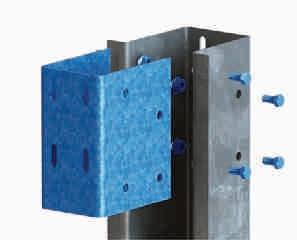
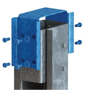
Step 2.2: Saddle Bracket installation on GC461C Wide Flange Post
2.2.1 Attach Wide Flange Center Saddle Bracket onto the top of the Wide Flange Center Post using eight 1/2-13 hex bolts and serrated flange nuts. Tabs on Center Saddle Bracket must be on East side.
2.2.2 Align Wide Flange Center Saddle Bracket with plane of table.
2.2.3 If Center Post is out-of-plumb in the E-W direction, Drive Housing shall be installed uphill on the Saddle Bracket opposite the direction the out-ofplumb Center Post is pointing. Doing this is important to maintain system operation within the designed tilt ranges.
2.2.4 Torque to specification. Saddle Bracket may need adjustment per Step 2.5.
Step 2.3: Saddle Bracket Installation for Standard Z Posts
2.3.1 If Z Posts are used as Standard Posts, make sure to use GC6610L Long Saddle Brackets.
2.3.2 Attach Long Saddle Brackets onto the tops of the Standard Posts using 1/2-13 hex bolts, washers and serrated flange nuts (2 sets per side).
2.3.3 Torque to specification.

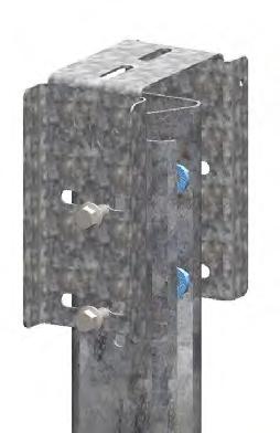
Step 2.4: Saddle Bracket Installation for Standard W Posts
2.4.1 Attach Standard Saddle Brackets onto the tops of the Standard Posts using 1/2-13 flange head bolts and serrated flange nuts. Torque to specification. Open end crowfoot wrench may be required to extend torque wrench.
2.4.2 If open end crowfoot is used, follow Step 2.8.1.
STANDARD BEARING ASSEMBLY
1 Standard Post (Wide Flange)
2 Standard Saddle Bracket
Step 2.5: Suggested Means & Methods for Saddle Bracket Alignment
Using barrel laser to align Saddle Bracket:
I Ensure Posts are installed within tolerance shown in Install Manual
2.5.1 If using Single Piece Bearings, it is recommended to stage the Bearing Housings and saddle bracket at each post location. Install Saddle Brackets onto posts and leave finger tight.
2.5.2 Create bearing target. The crosshair of target shall be in the middle of the bearing housing.
2.5.3 Set up the laser at the last post at the east west centerline of posts, and 6” [152 mm] above top of post. Shoot laser to post at opposite end of table ensuring laser is directed at the east west center of that pile. Adjust laser so that it shoots to 6” [152 mm] above top of post at opposite end.
2.5.4 Measure North-South slope of laser. Set NorthSouth slope of saddle bracket tops to match the slope of the laser prior to tightening bolts connecting saddle bracket to post.
2.5.5 Tighten bolts connecting saddle bracket to post at northmost and southmost posts in table with the bolts going through the saddle brackets at center of slots in the posts.
2.5.6 Place bearing target on last post and move bearing target east/west until laser is directed at center of crosshairs. Tighten saddle bracket when target achieved. Make permanent marker mark on saddle bracket indicating where bearing housing should sit east/west.
2.5.7 Place bearing target on next post and confirm laser is directed at center of crosshairs. Make permanent marker mark on saddle bracket indicating where bearing housing should sit east/west. Repeat this step until marker marks have been made for all intermediate saddle brackets.
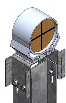
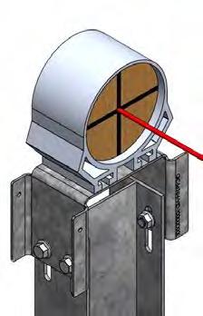
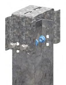
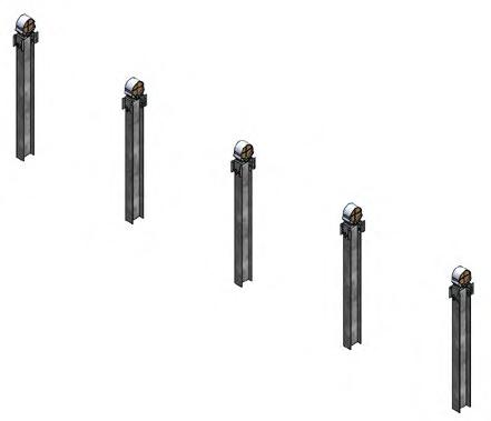
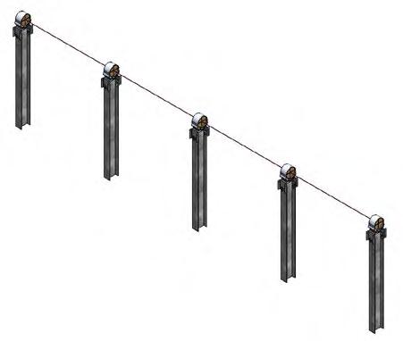
Step 2.6: Center Bearing Installation
2.6.1 Attach Drive Housing onto Saddle Bracket on Center Post using six 1/2-13 carriage bolts and serrated flange nuts. (Grade 8 or grade 5 nuts may be provided for use with carriage bolts ONLY; consult Project Construction Drawing) Leave nuts finger tight.
2.6.2 Ensure assembled Center Bearing Collars have 6 Bearing Wheels included. Ensure each assembled Standard Bearing Collar has two Bearing Wheel, Single Piece inserts in them. Ensure each assembled Standard Bearing Collar Heavy has two Bearing Wheel, Single Piece inserts in them. Refer to Post Schedule for selecting Bearing Collar Widths for each Post.
2.6.3 Pre-stage assembled Center Bearing Collars onto the Row Tube to be installed onto the Center Post, along with appropriate number of assembled purlins and assembled Standard Bearing Collars.
! Prestaging can occur in the laydown yard or in the field.
2.6.4 Take assembled purlins and pre-position along a Row Tube by loosening the flange nuts enough that the space between the Reinforcement Channel and Purlin Channel is larger than the Row Tube, and sliding the appropriate number of assemblies onto the Row Tube at the approximate locations they will be needed.
2.6.5 Slide the Bearing Collars along the Row Tube approx. 6” (152mm) to the North or South side of the Saddle Bracket.
2.6.6 Rotate Bearing Collars 90° so that the bottom slots face the installer. Pre-stage 1/2-13 carraige bolts into Bearing Collar slots such that spacing of bolts matches slot spacing on Saddle Bracket (6 per CenterSaddle Bracket, 4 per Heavy Saddle Bracket, and 2 per Standard Saddle Bracket).
2.6.7 Rotate Bearing Collar back so bolts are facing down towards the ground.
2.6.8 With hand on top of Bearing Collar, slide back over Saddle Bracket.
2.6.9 Lower Row Tube, guiding Bearing Collar with hand on top so that bolts fit into Saddle Bracket Slots. If bolt alignment adjustment is needed, use wrench or similar tool to tap bolts into alignment.
I Never place hand or body part between Bearing Collar and Saddle Bracket.
! If provided use bearing fork tool to keep bolts aligned with slots in saddle bracket.
2.6.10 Center Bearing Collars shall be centered on Saddle Bracket to within +/- 1° of the Row Tube (North-South table slope). Torque hardware to spec. Use crowfoot wrench if necessary, and reduce torque as per instructions in Step 2.8.1 if crowfoot is used.
! For ease of installation. Bearings on Center Posts must be centered relative to the centerline of the Center Post to within +/-1/2 inch [12mm] E-W. Bearings on Standard Posts must not exceed +/- 1 inches [25mm] E-W adjustment.
! If Center Post is off-plumb in the E-W direction, Center Bearing Collar shall be installed uphill on the Saddle Bracket opposite the direction the off-plumb Center Post is pointing. Doing this is important to maintain system operation within the designed tilt ranges.

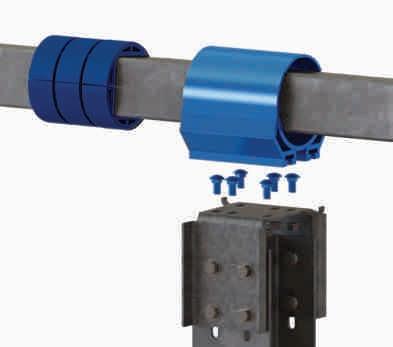
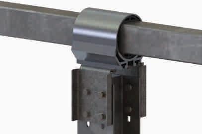
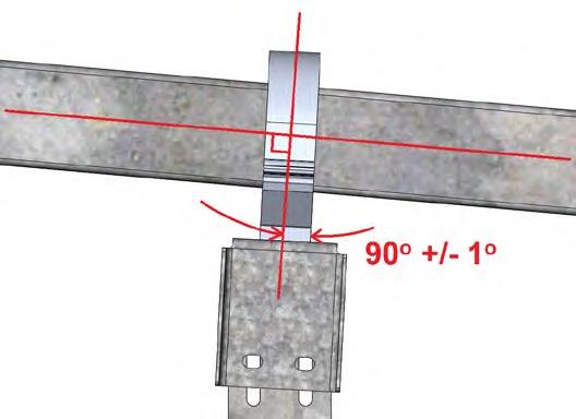
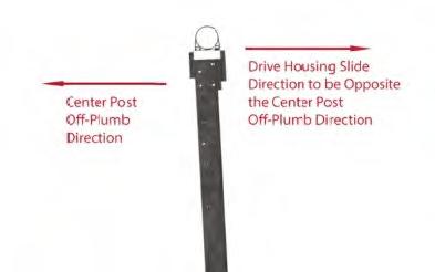
Step 2.7: Standard Bearing Installation
2.7.1
2.7.2
2.7.3
Pre-stage assembled Standard Bearing Collars onto the Row Tube to be installed on the Standard Posts, along with appropriate number of assembled purlins and assembled Squeeze Splices.
! Prestaging can occur in the laydown yard or in the field.
Slide Bearing Collars along Row Tube approx. 6” [152mm] to North or South side of Saddle Bracket. Rotate Bearing Collars 90° so bottom slots face worker.
Pre-stage 1/2-13 carriage bolts into Bearing Collar slots such that spacing of bolts matches slot spacing on Saddle Bracket (4 per Heavy Saddle Bracket, and 2 per Standard Saddle Bracket). Rotate Bearing Collar back so bolts are facing down.
2.7.4 With hand on top of Bearing Collar, slide back over Saddle Bracket. Lower Row Tube, guiding Bearing Collar with hand on top so that bolts fit into Saddle Bracket Slots. If bolt alignment adjustment is needed, use wrench or similar tool to tap bolts into alignment. All Bearing Collars shall be aligned to within+/- 1° of the Row Tube (North-South table slope). The bolts connecting the Bearing Collar to the Saddle Bracket shall be within the Bearing Collar slots such that the Bearing Collar is roughly centered on the Saddle Bracket. Bearing Collars shall not stick out past the flat of the Saddle Bracket.
I Never place hand or body part between Bearing Collar and Saddle Bracket.
! If provided use bearing fork tool to keep bolts aligned with slots in saddle bracket.
2.7.5 Torque hardware to spec. Use crowfoot wrench if necessary, and reduce torque as per Step 2.8.1 if crowfoot is used.
! Standard Post Bearings have substantial vertical (up to 2.5 inches [63mm]) as well as lateral flexibility to allow for ease of installation. Bearings on Center Posts must be centered relative to the centerline of the Center Post to within +/-1/2 inch [12mm] E-W. Bearings on Standard Posts must not exceed +/- 1 inches [25mm] E-W adjustment.
I The Bearing Assemblies and Saddle Brackets shall be installed perpendicular to the Row Tube to within 90-deg +/- 1-deg relative to the axis of the Row Tube. Otherwise, misalignment will cause premature failure of the plastic Bearing Wheels.


STANDARD HEAVY BEARING (NO CARRIAGE)


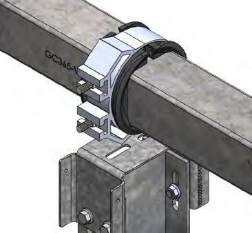
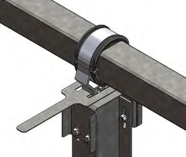
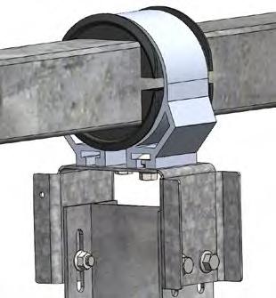
Step 2.8: Torque Requirement Modification with Torque Wrench Extender
2.8.1 If a torque wrench extender (open-end crowfoot) is used, the required torque as measured by the torque wrench shall be reduced by the ratio of the length of the torque wrench over the overall length of the torque wrench including the additional length of the extender.
For example:
Torque wrench length = 12 in [305 mm]
Extender length = 1.5 in [38 mm]
Required torque = 75 ft-lbs [101.6 N-m]
Modified torque as measured by the torque wrench = (75 ft-lbs) * (12 in) / (1.5 in +12 in) = 67 ft-lbs [90.8 N-m]
ADAPTER DRIVE CENTERLINE
Step 3: Tube Installation
3.1 Install Row Tubes into Bearings as described in Bearing Installation section and position Row Tubes relative to the Posts according to Project Construction Drawings.
3.2 Join one Row Tube to the next using preassembled Squeeze Splices. Tubes along each tracker table must be straight with deviation of no more than ± 1/2” [12 mm] along the line. Install squeeze splices at each tube to tube connection within a table, using 8 1/2” bolts and flange nuts per connection. Install the 1/2” hex bolt (not flange) with the thread pointing away from the panel. Once all Row Tubes for a single table are joined, tighten all hardware to specification.

3.2.1 Minimum tube-to-tube spacing is ¼” (6mm) and max tube-to-tube spacing is ¾” (18mm). Allowable distance from face of tab to face of either tube is 0” to ¼” (6mm).

3.2.2 If one end of the tube is notched, make sure the tab on at least one side of the tube is not notched.

3.3 Place preassembled squeeze splice fully on the end of one tube such that tab in middle of squeeze splice is up against the end of that tube. Using heavy lifting equipment, align both tubes to be connected such that there is a small gap between the open end of the preassembled squeeze splice and the second tube. Slide just the squeeze splice so that the ends of both tubes are in the splice (i.e. the splice spans the gap between the two tubes). Then push the tube segment on the lifting equipment into position such that the ends of both tubes are adjacent to the tab in the middle of the squeeze splice.
3.4 Squeeze Splice shall be hand tightened first, then tightened in a star pattern, alternating sides. Then apply final torque in a star pattern, alternating sides. Refer to numbers for order of torquing.
3.5 Tubes along each tracker table must be straight with deviation of no more than ± 1/2” [12 mm] between bearing housings and 1” [25 mm] along the entire table length.
3.6 Tubes may vary in length due to manufacturing tolerances. Typically, tolerances within 1/2” [12 mm] will not affect installation. If lengths vary outside of typical tolerance, please consult with GameChange on options to keep table lengths consistent with Project Construction Drawings.
3.7 See Step 4 for Row Tube to Row Tube spacing between adjacent tables North South.
3.8 Row Tube may deflect up to 2” [50 mm] under self weight (including modules) in middle of span.
3.9 The minimum allowable row tube overhang measured from the last bearing collar to the end of the tube is 1” (2.54 cm). See diagram below.
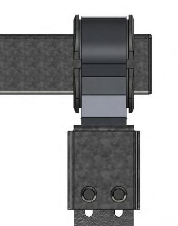
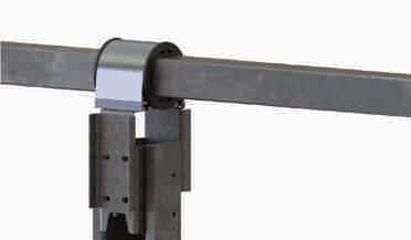
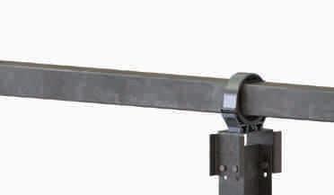



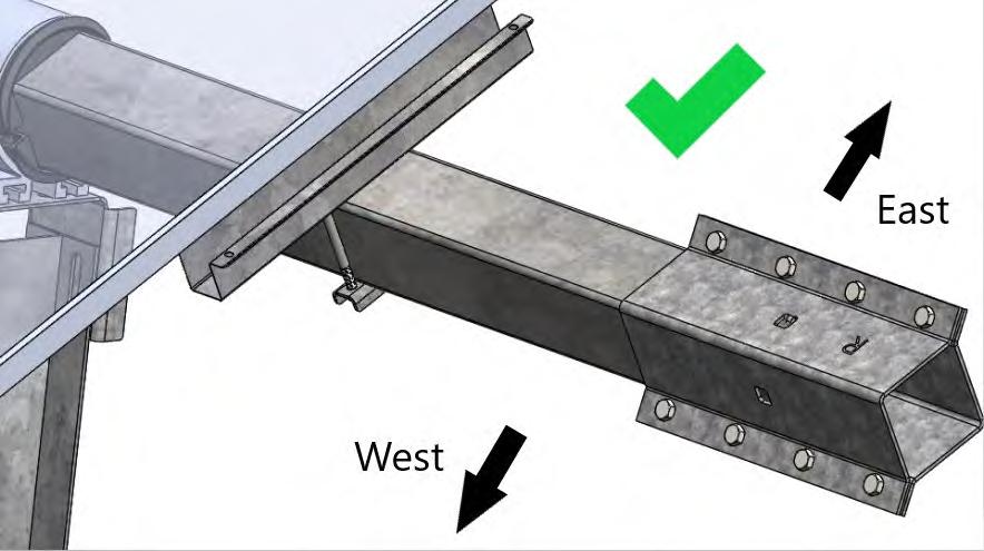
Step 4: Adjacent Table Spacing
4.1 Adjacent tables are tracker tables aligned along their North/South axes. These tables must be within 18” [457 mm] from final module edge to final module edge. Module edge spacings between 12” [305 mm] and 18” [457 mm] must be analyzed on a project-specifec basis to determine if they can be classified as adjacent tables.
4.2 Adhere to the following North/South table gap requirements for adjacent tables.
4.2.1 Module edge to Module edge gaps shall be 18” [457 mm] or less, but not less than 2” [50 mm].
4.2.2 Tube to Tube gaps shall be 16” [406 mm] or less, but not less than 2” [50 mm] (unless First Solar Series 4 modules in which case see Project Construction Drawings).
4.2.3 Field cutting of Tubes may be required to achieve these requirements.
4.3 The maximum allowable vertical (up and down) gap is 2” [50 mm] between end of one table and the end of the adjacent table.
4.4 The maximum allowable east-west gap is 2” [50 mm] between the end of one table and the end of the adjacent table.

Step 5: Attaching Tube Caps
5.1 Tube ends shall be covered using rubber Tube Caps as shown.
NOTE: Construction grade adhesive such as Liquid Nails may be used to glue the Tube Caps in place.
Alternate Cap designs may be provided.
Step 6: Drive Housing Fixturing to Saddle Bracket
6.1 If Center Post Saddle Brackets are provided with 9/32-inch holes, TEK screws are required. Once Row Tubes are installed straight on all tables within a row, the Center Post Drive Housing shall be TEK screwed onto the Center Post Saddle Bracket.
6.1.1 For tables with slopes of 5% or less, two TEK screws are required (one per side).
6.1.2 For tables with slopes greater than 5%, four TEK screws are required (two per side).
6.2 Pre-drill 3/16” hole into the Drive Housing prior to installing TEK screws.
I DO NOT DRILL THROUGH MORE THAN 3/4 INCH PAST THE SADDLE BRACKET WITH DRILL BIT OR TEK SCREW. OTHERWISE, THE INNER DIAMETER OF THE CENTER BEARING COLLAR MAY BE PUNCTURED.
As an Alternative to the 1/4" TEK screws, install Ramset 3/4" Premium step pins with domed washers (Ramset Part Number MO34BB) with a Ramset T3SS or T4SS Single-Shot Gas Tool.


Based on positioning of the Drive Housing to the Saddle Bracket, select holes on the Saddle Bracket that are best centered to the flat surface of the Drive Housing that can be seen through the holes.
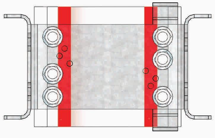
Step
7:
Driving Arm Installation
7.1 Driving Arms typically deliver with all components preassembled. If not, consult GameChange for assembly instructions.
7.2 To install the drive arm onto the Row Tube:
7.2.1 Of the eight long 1/2-13 threaded rods (or hex bolts) that will come preassembled on each Driving Arm, remove the four outer threaded rods (or hex bolts).
7.2.2 Remove the Spacer Bracket (Angled).
7.2.3 Slide the Driving Arm assembly onto the Row Tube.
7.2.4 Replace the Spacer Bracket (Angled).
7.2.5 Reinstall the four threaded rods (or hex bolts) handtight.
7.3 Install the Driving Arm assembly pointed up. Center the Driving Arm assembly around the Drive Housing. Lower Driving Arm Assembly onto Row Tube such that Row Tube falls between Ridgeback plates as shown. Tap inwards on all Ridgebacks until the sides are flush against the Drive Wheels.
NOTE: If Ridgebacks on both sides are not in contact with the Drive Wheels, be sure Ridgebacks on uphill side is in contact with the Drive Wheels on the uphill side.
7.4 Torque down the nuts on all eight long threaded rods (or hex bolts) to spec so the Driving Arm squeezes onto the Row Tube.
7.5 Once all Row Tubes for a table are installed, rotate Driving Arm assembly such that the Driving Arm is pointed WEST
NOTE: Only for GC6601 (or GC5601) Two Piece Bearings, see Bearing Orientation, below, and Appendix E.
7.6 Install one 3/8-12 serrated TEK screw through each bottom Ridgeback, Driving Arm and Row Tube as shown. Install one TEK screw into each hole until snug fit. Use 11/32” drill bit to pre-drill row tube for TEK screw.
7.7 For 4600F, 4600FH, and 5605FH Driving Arms, remove shipping straps after installation.
GC6601 (or GC5601) Bearing Orientation
For two piece bearings (GC6601 and GC5601), the gaps between the two halves of the bearing must be oriented vertically (see below).
Single Piece Bearings (GC6601S and GC5601S) do not require a specific bearing orientation.
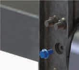


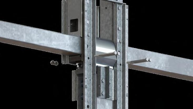
I Any 1/2” hardware delivered with the Driving Arm Preassembly cannot be used anywhere else. If any are loose or was required to be loosened to re-square the Driving Arm Preassembly, retorque to 60-70 ft-lbs [81.3 - 94.9 N-m].
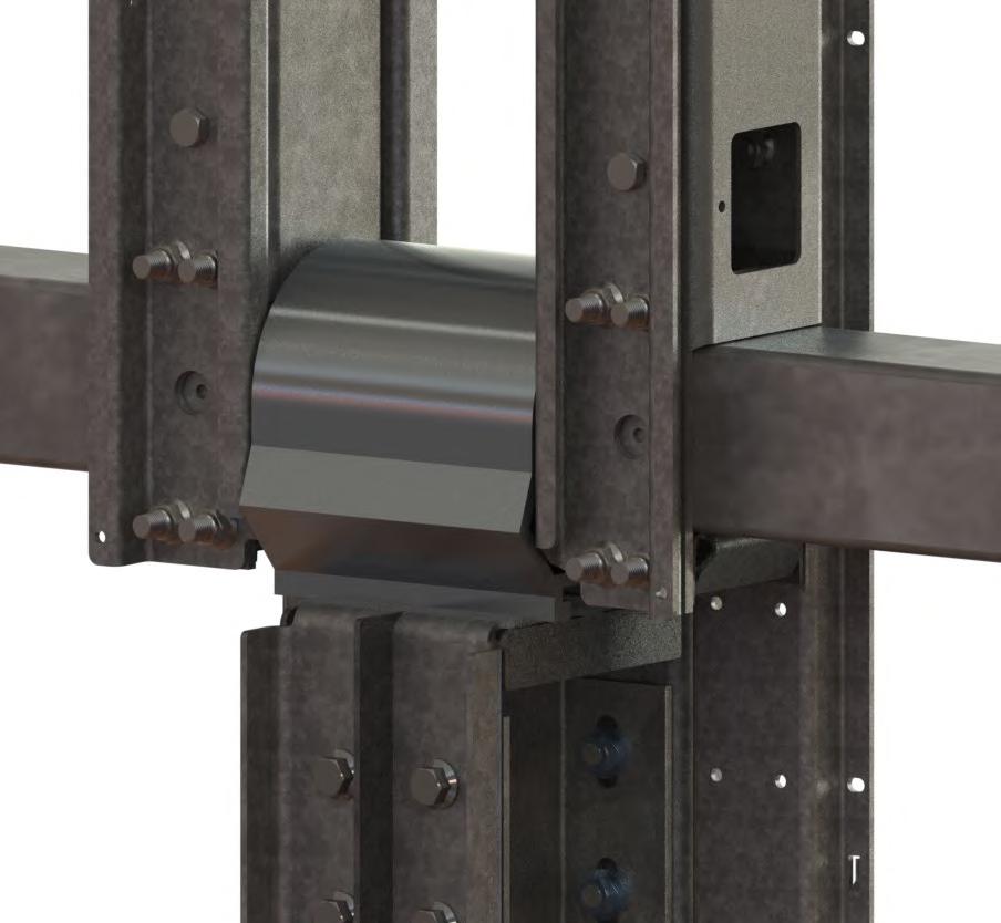
I For two piece bearings, gaps between Bearing Wheels must be vertical when Driving Arm is horizontal.
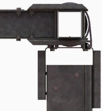
Step 8: Actuator Installation
I Actuators are delivered pre-set at maximum ROM. I Do not spin out Actuator tube or else Actuators will fail, system will not function and warranty will be void. Handle Actuator with extreme care, especially the motor end. Make sure the Bottom Bracket is above ground level. Do not carry actuator by the cable meant for connection of the actuator to the controller. Doing so will damage the connection to the actuator. Do not remove tape until after actuator is installed.
8.1 Check that the Actuator piston tube (“stroke”) is not loose or detached from the body of the Actuator. There should be no play in the piston tube, and it should be fully retracted inside the body of the Actuator. If this is not the case, contact GameChange Solar.
8.2 Orient the Actuator with the stroke end directed towards the Bottom Bracket and the motor end towards the Driving Arm with the motor facing away from the Center Post.
8.3 Attach the Actuator to the Center Post and Driving Arm Assembly
I Make sure not to rotate the stroke end, and do not break the tape holding stroke to Actuator body.
8.3.1 Mount Bottom Bracket to Center Post on the West side.
8.3.1.1 Install Bottom Bracket onto Center Post near the ground using 1/2-13 hex bolts and serrated flange nuts.
I Make sure the Bottom Bracket is above ground level.
8.3.1.2 Bottom Bracket may need adjustment per Step 8.3.2.
Locate bottom bracket such that distance from bottom of Saddle Bracket to top of Bottom Bracket matches that shown in Elevation Drawings in Project Construction Drawings.
8.3.1.3 Torque to specification.
8.3.1.4 Align hole at stroke end of Actuator with holes on the Bottom Bracket.
8.3.1.5 Attach stroke end of Actuator using the following stackup: 1 1/8-7 x 7 inch length hex bolt, Bottom Bracket wall, Actuator Spacer, Actuator stroke, Actuator Spacer, Bottom Bracket wall, and Nyloc jam nut. The Nyloc jam nut shall be turned until flush with the wall of the Bottom Bracket and then torqued to specification. Spacers shall be able to spin freely, however, max gap between spacer and bottom bracket shall not exceed 1/4” [6 mm].
NOTE: Tables shall be left in stow when not being actively worked on prior to commissioning. For ease of panelization or wire installation, table may be temporarily rotated up to 25 degrees East position while wind speed is under 22 mph [10 m/s]. Table shall be rotated back to stow when not actively being installed.
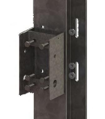
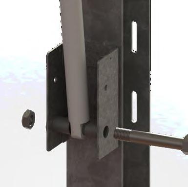
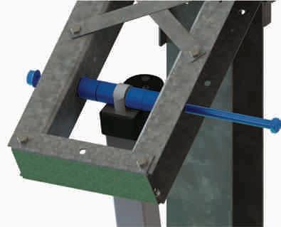
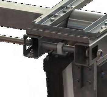
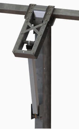
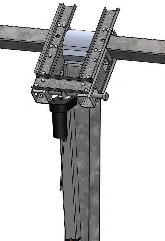
8.3.2 Attach motor end of Actuator using the following stackup: 1 1/8 inch x 9 inch length hex bolt, Driving Arm wall, 2 Actuator Spacers (or Top Spacer), Actuator motor end, 2 Actuator Spacers (or Top Spacer), Driving Arm wall, and Nyloc jam nut The Jam nut with nylon patch shall be turned until flush with the wall of the Driving Arm and then torqued to specification. Spacers shall be able to spin freely, however, max gap between spacer and Drive Arm shall not exceed 1/4” [6 mm].
8.3.3 If Nyloc nuts are used. Spray Nylon portion of all Nyloc nuts with outdoor rated gray paint approved for plastic such as Rustoleum Industrial Enamel.
NOTE: If the top and bottom eyelets do not align, contact GameChange Solar Engineering for alignment instructions.
I Instructions to aid in proper Driving Arm tilt
• For the distance from the bottom of the Center Saddle Bracket to the top of the Bottom Bracket refer to assembly views.
• Aim to install the Center Saddle Bracket to the center of the top slots in the Center Post.
• Aim to install the Bottom Bracket to the center of the bottom slots on the Center Post.


8.4 Verify Driving Arm tilt.
8.4.1 Driving Arm tilt must be adjusted to be within +1/-0 degree of maximum tilt to the West. Bottom Bracket, Center Saddle Bracket and Center Bearing Collar shall be used to adjust the Driving Arm tilt.
8.4.2 If Driving Arm tilt is further than 1 degree from the maximum Western tilt per system design, the Bearing Collar location, Center Saddle Bracket, and Bottom Bracket may be adjusted to get the Driving Arm tilt to within tolerance.
8.4.2.1 Bottom Bracket can be loosened from the Center Post and the vertical adjustment can be used.
8.4.2.2 Center Saddle Bracket can be loosened from the Center Post and the vertical adjustment can be used.
8.4.2.3 Note: Row Tube and adjacent Standard Post Bearing Assemblies may be affected. Be sure Row Tubes are realigned if this adjustment is utilized.
8.4.2.4 Bearing Collar can be loosened from the Saddle Bracket and the lateral adjustment can be used.
! Note: Row Tube and adjacent Standard Post Bearing Assemblies may be affected. Be sure Row Tubes are realigned if this adjustment is utilized.
8.4.2.5 Retorque all hardware if they were loosened in Step 7.
8.5 Attach Actuator wire firmly every 1 ft [0.305 m] running from the Actuator motor along the Drive Arm using cable ties through the pre-punched ¼ inch [6 mm] holes provided. When wire reaches the Row Tube, make sure to leave 1 ft [0.305 m] of slack to allow for table rotation. Run wires to the location where the Node Controller will be located, continuing to cable tie the Actuator wire to the Row Tube at this point. Be sure to provide sufficient slack to allow full table rotation, make sure to avoid areas where wires may be chaffed or pinched. Leave Actuator wire hanging down to prevent water ingress into the converter. Plug into controller as soon as controller is installed.
8.6 If there is reason to suspect local wildlife will chew on the wires running from the Actuator or any other wires, make sure to protect the wires with appropriate armoring.
8.7 DO NOT manually extend or retract the Actuator for any reason. This can damage the Actuator and cause the warranty to be void.
8.8 If Actuator must be operated prior to commissioning, only use GCS Rotator Harness.
8.9 If Project Construction Drawings require the installation of a Stow Arm assembly with Shock Absorber, refer to Step 11 for details.
8.10 If Rotator Harness is being used, trackers must be rotated to stow if wind speed is over 20 mph and when installation work is not actively occurring.

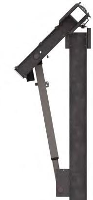
Step 9: Node Controller and Charging Module Installation
I Prior to installing controllers, ensure E-Stops are pressed in and Actuator Power Connector cover is firmly in place.
I Do not carry node controller by the cables meant for connection of the controller to the Small Charging Module or actuator. Doing so will damage the connection. If cables are zip-tied or taped, do not remove until installing onto Row Tube and to the Small Charging Module.
I Ensure proper space in provided around the Node Controller so that the emergency stop is easily accessible.
I Installer will notify GameChange Solar 90 days before node controllers are ready to be installed, fused, and plugged into Small Charging Module. GameChange will then deliver node controllers which must be installed, fused, and plugged into Small Charging Module within 2 weeks of delivery to site, or irreparable damage to battery may occur and void warranty on battery. All costs for battery replacement will be borne by customer/ installer.
I For Projects Located in Canada
For Projects Located in Canada, the controller installation, including wiring methods, shall be in accordance with the Canadian Electrical Code or CSA C22.1.
Any malfunctioning node controller shall be uninstalled and replaced with a new, GameChange Solar-supplied node controller.
All conductors and cables associated with the node controller, actuator, sensors, and charge module shall be managed so that a bend radius equal to or greater than 5 times the radius of the cable is maintained throughout articulation of the tracker. Failure to adhere to this requirement will void the warranty associated with damage incurred where not installed properly.
Step 9.1: Standard Node Controller and Charging Module Installation
I Do not carry the Charging Modules by the cables. Doing so will damage the connection. If cables are zip-tied or taped, do not remove until installing onto Drive Arm.
Step 9.1.1: Charging Panel Installation
9.1.1.1 Install Long Charging Panel on the Driving Arm by first removing the two pre-loaded 1/4” star bolts and serrated flange nuts. Place the Charging Module onto the fingers on the Driving Arm and slide the module such that the hardware can be re-installed onto the Driving Arm - torque to spec (See Detail B).
I The charging panel must be centered ± 1/8 inch [3mm] over the center post and row tube.
Note: Charging Module shall be installed such that the Junction Box is on the East side of the tracker.

Step 9.1.2: Alternate Charging Panel Installation
9.1.2.1 Place the Charging Module onto the fingers on the Driving Arm on the side and install the 3/16” bolt, 3/16” 0.62” OD washer, and 5/16” star washer on one side and a 3/16” 0.56” OD washer and 3/16” Nyloc Nut on the other.- torque to spec. 1/4” hardware method allowed where fits.
9.1.2.2 If the Tab to Tab distance on the GC4600 and GC5605 Driving Arm is wider than the transverse slot hole distance in charging module: Loosen the 4 ½-1 Bolts on 4680A & 4680B (or 5680A & 5680B) to reduce the width (there is an additional 0.04” allowance). Loosen the 4 ½-1 Bolts on GC4684 (or GC5684) to adjust distance between driving arms. Pull the ridgebacks inward. After ridgebacks have been adjusted, verify tabs are at distance where they will fit into the slots on charging panel frame. Torque 1/2” bolts to 60-65 ft-lbs [81.3-88.1 N-m]. See GameChange Engineering for additional Information.
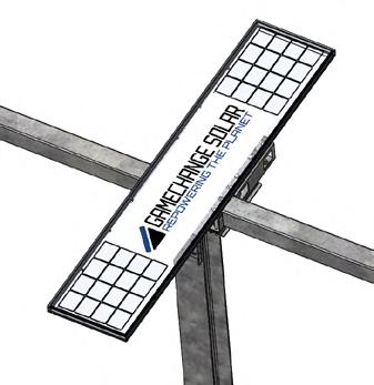
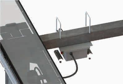


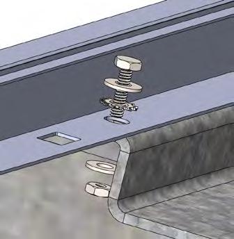
Step 9.1.3: Node Controller Installation
9.1.3.1 Install controller assembly using 3/8” U bolts, nuts, and Purlin Channels to attach the Node Controller to the Row Tube.
I Do not carry Node Controller by the cables meant for connection of the controller to the charging module. Doing so will damage the connection to the charging module. If cables are zip-tied or taped, do not remove until installing onto Row Tube and to the Charging Module.
I Be sure all nuts are finger-tight then torqued to 10 ft-lbs [13.5 N-m].
I Node Controller shall be centered under the first PV module adjacent to the Wind Break Plate. Make sure controller is installed to the south of the Center Post with E-Stop facing the Center Post.
I Distance between Center Post and Controller should be a minimum of 18 inches [0.457m].
I DO NOT connect the wiring to Solar Panel until the fuse is inserted (see Detail A). This could result in improper charging cycle.
9.1.3.2 Insert Node Controller Fuse (15A) into Node Controller Fuse Holder using a Phillips Head screw driver (Detail B). Tighten Fuse Holder Cap to 7 in-lbs [0.8 N-m].
I Care shall be taken when inserting Node Controller Fuse. Pushing Fuse into Fuse Holder with excessive force will damage Fuse.
9.1.3.3 Plug actuator cable into connector on node controller. When properly connected, an audible click is heard when plugging the Actuator Connector into the Node Controller. Ensure that Actuator connector is securely connected to Node controller.
9.1.3.4 Plug Charging Panel wires into mating wires on Node Controller. When properly connected, an audible click is heard when plugging the Charging Panel wires into the Node Controller. Ensure that Charging Panel wires are securely connected to Controller.
9.1.3.5 Ensure that Charging Module is connected to Node Controller no later than one hour after inserting the fuse otherwise the battery may drain.
I Install Node Controller and connect Charging Module to Node Controller no later than 2 weeks after the batteries are delivered. Delay in connecting Node Controllers to Charging Module may cause irreparable damage to battery in Node Controller.
9.1.3.6 Scan Node Controller Barcode using the GCS Web App.
9.1.3.7 Release E-Stop on Node Controller. This may require either a twist or pull motion.
9.1.3.8 Verify that the green LED in the LED window is lit.
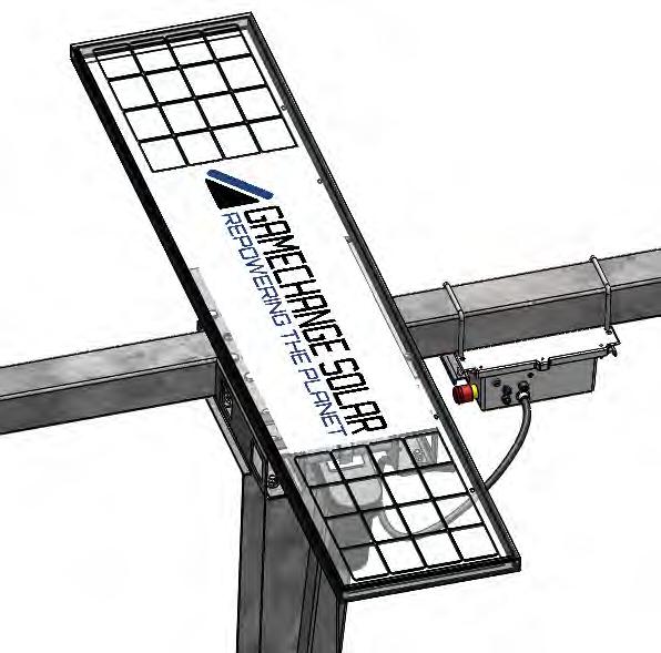
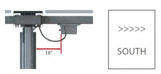


Step 9.2: Drive System Wire Management
9.2.1 Attach Actuator wire to the westmost edge of the drive arm, on the side of the drive arm closest to the node using a Hellermann Tyton Aerial Support Tie (Part 111-01671) or equivalent as shown below. Leave at least 10” (25.4 cm) of cable on the actuator side of the tie and at least 1’ (2.5 cm) of slack on the node side. Make sure the cable is straight, i.e. does not have any axial twists.

9.2.2 Attach Charging Module wires to the flange of the ridgeback closest to the node controller using a Hellermann Tyton Aerial Support Tie (Part 156-00592) or equivalent as shown below. Leave at least 12” (30 cm) of cable on the charging panel side of the tie.
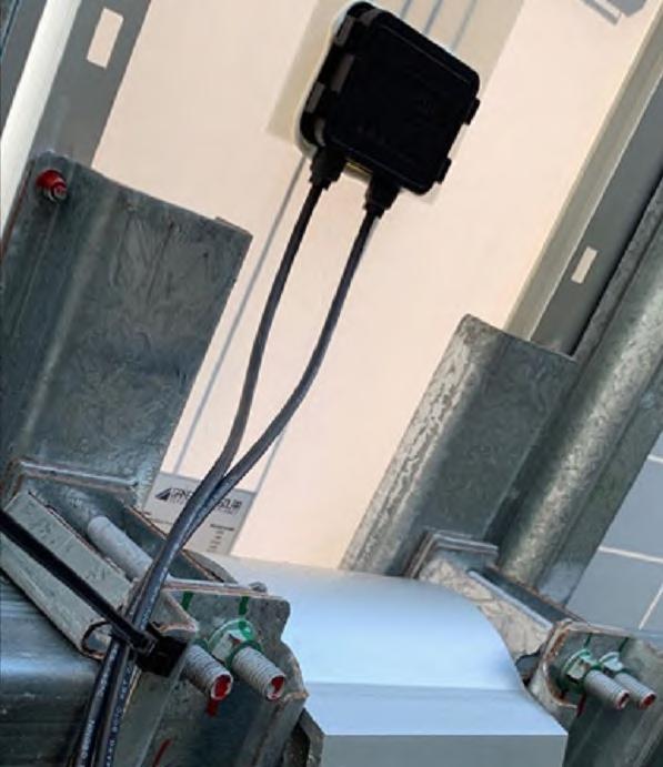
Step 10: Purlin Installation
10.1 Install Purlin onto Row Tube using Purlin Channels (GC4378LU or GC5978LU ones with slots on the Purlin side and GC4378BU or GC5978BU with holes on the Row Tube side), Reinforcement Channel (GC4378W or GC5978W only if provided), 3/8” Thru Bolts, and serrated flange nuts. Purlins and Purlin Channels shall be centered on the Row Tube prior to torquing hardware. If Purlin Spacing Jig is not available, leave hardware finger tight so Purlins can be adjusted while mounting modules.
10.2 Purlins shall be attached at proper locations as noted on Project Construction Drawings provided by GameChange so that they are not located where Squeeze Splices or bearings are located.
10.3 After modules are mounted, torque grade 8/9 Thru Bolts to 30-33 ft*lb (40.6-44.7 Nm).
10.4 See Appendices C, D, and G for Glass/Glass, First Solar Series 6, and First Solar Series 7 Modules.
! Run first nut up to the GC4378BU or GC5978BU so that it is tightly against the tube, then repeat for other side. Then go back to first side and torque to spec, then repeat for other side.
! SUGGESTED MEANS & METHODS
It is recommended that the Purlin, Purlin Channels, and Thru Bolts are preassembled prior to staging them along the length of the Row Tube.
! ASSEMBLING PURLINS
Purlins may not come pre-assembled. If they are not preassembled, assemble them by place the Purlin inside the Reinforcement Channel. Next, place the Purlin Channel Bottom GC4378BU or GC5978BU inside the Purlin Channel Top GC4378LU or GC5978LU. Place the two Channels inside the Purlin. Insert the 3/8” square head thru bolts through the Channels and Purlin and place on top of Row Tube. On the other side of the Row Tube, insert a Purlin Channel Bottom GC4378BU or GC5978BU through both bolts. Place 3/8” nuts (colored Dark Blue) on the bolts and leave nuts loose enough to place them as needed along the Row tube. Once Purlins are set, torque to spec.
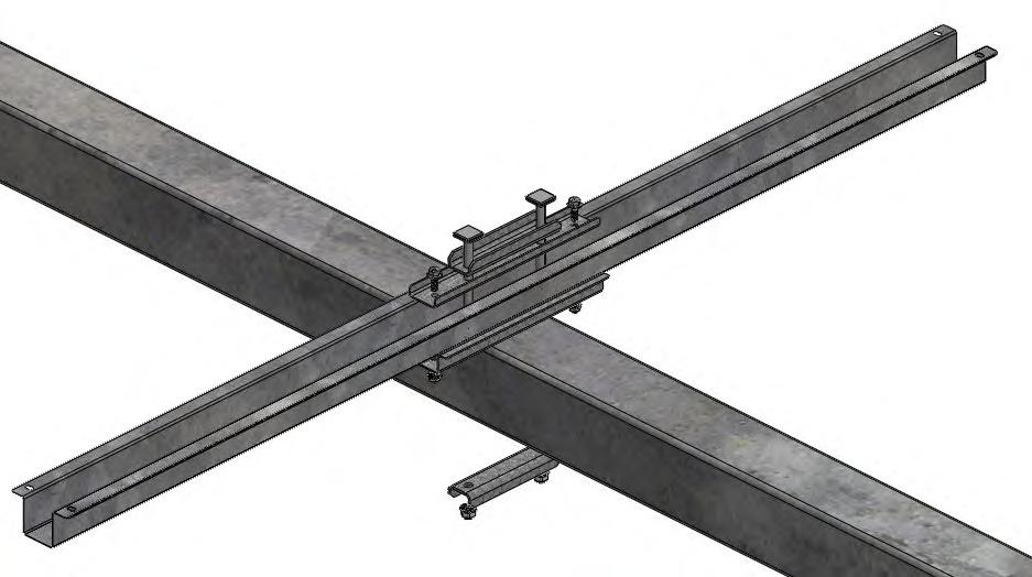


Step 11: Damper Installation
11.1 If required, pre-assemble Damper Arm Assembly using Damper Arm Ridgeback Top, Damper Arm Ridgeback Bottom, Spacer Bracket - East, and Spacer BracketWest using 1/2-13 hex bolts and flange nuts.
11.2 At Post locations that require Dampers (see layout), attach Damper Arm Assembly to Row Tube using 1/2-13 x 6” Long hex bolts and flange nuts.
11.3 Use 11/32” drill bit to pre-drill row tube for TEK screw. Install 3/8-12 TEK screw into each Damper Arm Assembly using the predrilled hole in the bottom of the Damper Arm assembly.
11.4 Place the Damper Arm on either the North or South side of the post. Damper Arm must be on same side of the Post as the Damper Bottom Bracket and sticking out the same direction as the Driving Arm. The distance measured from the edge of the Post flange (or the edge of the Saddle Bracket, whichever is wider) to the edge of the Damper Arm Ridgeback shall be between 1 inch and 1 1/4 inch (2.5 - 3.2 cm). Be sure that the Damper Arm Assembly does not interfere with the Purlins.
Note: 1/2-13x6” Long Hex Bolts must be installed as depicted in the image to the right with the threads facing towards the ground and the bolt head facing the modules.
11.5 If possible, install the Damper Arm on the downhill side of the Post if doing so does not interfere with the Purlin.
11.6 For tables with a greater than 3% slope North-South or where the center post has a higher maximum stickup than standard (i.e. a topo Post; refer to stickup diagrams in the drawing set for maximum reveals), install damper arm with 1/2”x6” long bolts finger tight prior to panelization.
11.7 It is recommended that within 72 hours of panel installation, the tables should be rotated East-West twice through the full range of motion. After this is done, move the damper arm to meet gap tolerance between damper arm and saddle bracket / post flange. Torque 1/2”x6” long bolts to spec.
11.8 Damper Bottom Bracket Assembly comes with all hardware pre-loaded. Remove the M20-2.5x150mm Long long hex bolt, M20-2.5 Nut, 1/2-13 Hex Bolt, Nuts and Damper Spacers from the assembly. Attach inner and outer stow bracket to Standard Post using the 1/2 -13 Hex Bolts and Nuts. After Brackets are properly placed on the post, torque to Spec.
Note: Damper Bottom Bracket Assembly should be installed at the distance from the Saddle Bracket that is specified in the elevation drawings.
11.9 Insert M20-2.5x150mm Long Bolt through Damper Spacers and eyelet ball of Damper. The Damper Bottom Bracket has an “N” and “S” hole. If the Damper and Bottom Bracket are installed on the North side of the Post, be sure to insert the bolt through the “N” hole. If the Damper and Bottom Bracket are installed on the South side of the Post, be sure to insert the bolt through the “S” hole. Be sure to stage Damper Spacers along the Hex Bolt so there is a Damper Spacer on both sides of the Damper. Secure M20-2.5x150mm Long Bolt using M20-2.5 Nyloc Hex Nut. The Nyoc nut shall be turned until flush with the wall of the Bottom Bracket and then torqued to spec.
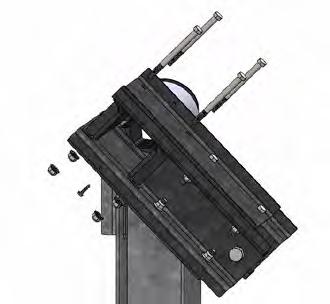
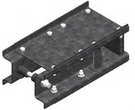
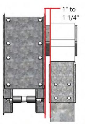
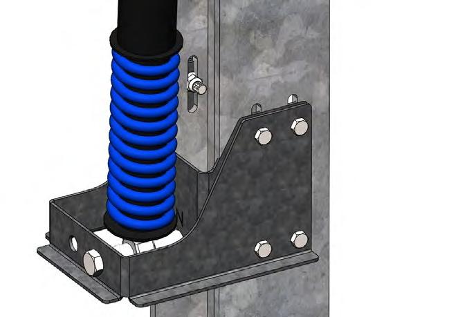
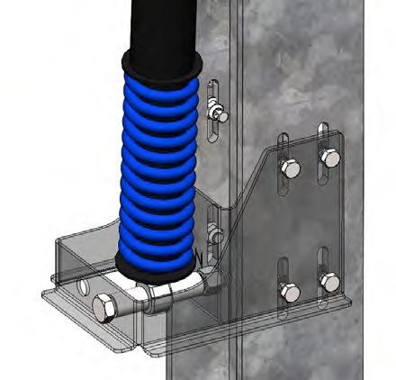
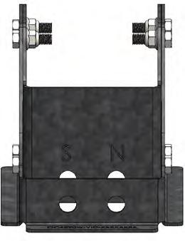
11.10
Attach top end of Damper to Damper Arm Assembly using M20-2.5x175 mm Long Hex Bolt and M20-2.5 Nyloc Nut. Be sure to stage the Damper Arm Spacer (Damper) along the hex bolt so that there is a Damper Arm Spacer on both sides of the Damper. Position Damper between Damper Arm Spacer so that Damper is centered in Damper Arm Assembly. Coat the Nyloc portion of the Nyloc nut with outdoor rated gray paint approved for plastic. (Rustoleum Satin Granite). The Nyloc nut shall be turned until flush with the wall of the Damper Arm and then torqued to spec.
I Do not drop or mishandle the Damper prior to install. Doing so can cause permanent damage to the Damper.
I Be sure to leave Damper hat loose on the spring.
I Be sure to install the Damper with the spring side down.
NOTE: Damper may need to be compressed in order to install. Otherwise, rotate the table up to flat during Damper installation in order to fit Damper’s at-rest length to arm and brackets. Be sure to rotate the table back to stow after Damper installation if the tables were rotated flat.
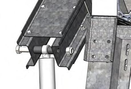
! INSTALLING GC4467D AND GC4567D ON THE SAME TABLE
When installing the Dampers (Rotation Limiting Damper GC4467D and/or Tracking Damper GC4567D) it is recommend to install them in the following manner: first, install the GC4467D while the tables are at the max ROM (refer to assembly drawings for max ROM); next, if GC4567Ds are required, rotate the table to flat using the provided Rotator Harness and install the GC4567D; finally, once panels are installed, return the table to stow after installation of the Dampers is complete.
If the GC4567D is installed on a flat table, do not rotate the tables from flat back to stow unless the modules are installed. Tables may remain flat if there are no modules installed; otherwise, if modules are installed, rotate the tables back to stow using the provided Rotator Harness. See Drive Arm install section for permissible wind speeds for panelization.
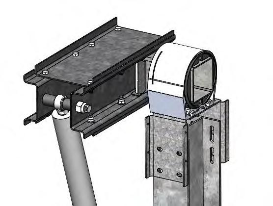
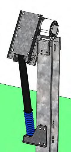
Step 12: Grounding
Modules are bonded to the Purlin, Row Tube and Center Post when fasteners are installed correctly. The overall grounding of the entire Genius Tracker system shall meet the standards of the edition of the NEC code in effect in the jurisdiction in which the project is located, in particular Article 690: Solar Photovoltaic Systems and Article 250: Grounding and Bonding, or equivalent local electrical standard.
It is GameChange’s understanding that the Standard Posts meet the intent of the requirements for grounding electrodes per NEC 2014 article 250.52.5 and therefore are effectively self-grounded. More specifically, article 250.52.5 calls out a minimum surface area for a galvanized steel rod or pipe of 1.57 ft2 [0.146 m2]. The exterior face of a GameChange Standard Post with a minimum embedment of 4 ft [1.219 m] has a surface area substantially in excess of the required 1.57 ft2 [.0146 m2]. Thus, sufficient contact exists between the steel post and the soil to transfer any charge that develops in the post.
I Please confirm with your local AHJ that the posts do not need to be bonded to the Row Tube, otherwise all Standard Posts must be connected to the Row Tube per step 12.1 Braided Jumper Installation. GameChange does not provide Braided Jumpers for all Standard Posts as default.
I The entire system needs to be grounded from any single point to an appropriate grounding source. **Please confirm with the project electrical engineer. Final confirmation that the solar array is properly grounded is within the scope of the Electrical Engineer of Record**
The grounding path is as follows: PV Module » Mounting Rail (speed clamp or purlin) » Torque Tube » Post » Grounding Lug » Grounding conductor to site grounding system. See Step 13 for PV module to purlin grounding using a star washer and Appendix B for PV Module to SpeedClamp™ via the bonding teeth. All other grounding connections are detailed in this section below.
If SpeedClamp™ or Purlin Remediation is Required
I CAUTION: Module removal may disrupt the bonding path and could introduce the risk of electric shock. Additional steps may be required to maintain the bonding path. Modules should only be removed by qualified persons in compliance with the instructions in this manual.
Prior to removing any SpeedClamp™ or purlin to which a braided jumper is connected, add a new braided jumper connecting the saddle bracket in the bonding path to an adjacent SpeedClamp™ or purlin that is not being removed. When the remediation work is complete, ensure a braided jumper is installed bonding the row tube to the saddle bracket to complete the bonding path from the tracker to a project grounding electrode.
The Panel to Purlin bonded connection is rated for up to 30 amps per bolt with star washer. All connections between structural members are rated for up to 200 amps; therefore, string wires with expected currents less than 30 amps may be installed on the racking system without installing additional grounding measures. String wires with expected currents between 30 and 60 amps may be installed on the racking system provided 4 bolts with star washers are installed per module. Wires and harnesses not in direct contact with a PV module may be supported by the tracker structure provided the expected current does not exceed 200 amps.
Braided Jumpers are required if posts are not self-grounded under local electrical code such that every post is bonded to the Row Tube with a Braided Jumper (see Grounding Section for more information). If Braided Jumpers are not available, trackers must be installed with UL Listed jumpers instead.
12.1 Bonding Center Post to Row Tubes (View A)
12.1.1 Place Braided Jumper over the flange of the Center Saddle Bracket and attach with a 1/4-20 x 3/4” long hex bolt and serrated flange nut.
12.1.2 Place the other end of the Braided Jumper on top of the serrated Flange nut already installed on the U-bolt or Thru-bolt, and parallel with the Purlin Channel of a nearby SpeedClamp or Purlin assembly.
12.1.3 Make sure the Braided Jumper is routed from the Post to the Purlin Channel such that it avoids sharp bends/cracking. Also, make sure the Braided Jumper is cured so that the 10” [254mm] of slack exists between the two connections.
12.2 Bonding the Actuator to the Driving Arm (View B)
12.2.1 Attach Braided Jumper to the 1/4 inch pre-punched holes provided on the side of the Driving Arm using 1/4-20 x 3/4” long bolts and serrated flange nuts.
12.2.2 Attach the other end of the Braided Jumper with the 1/4” TEK screw into the pre-drilled hole in the actuator (if not already connected).
12.2.3 Make sure the Braided Jumper is curved so that 10” [254mm] of slack is introduced into the component.
NOTE: For a list of alternate actuator setups, see Appendix K.
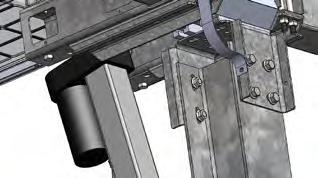
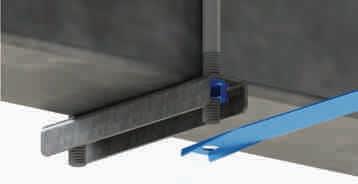

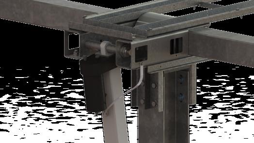
12.3 Bonding Row Tube to End Post (View C)
12.3.1 Place Braided Jumper over the hole in the flange of the Saddle Bracket and attach with a 1/4-20 3/4 inch long hex bolt and serrated flange nut.
12.3.2 Place the Braided Jumper on top of the serrated flange nut already installed on the U-bolt or Thrubolt at the end of the table and parallel with the Purlin Channel of a nearby SpeedClamp or Purlin assembly. Secure in place with a second serrated flange nut, and torque to specification.
12.3.3 Make sure the Braided Jumper is routed from the Post to the Purlin Channel in such a way as to avoid sharp bends/cracking. Make sure the Braided Jumper is curved so that 10” [254 mm] of slack is exists between the two connections.
12.3.4 To achieve grounding of the system to an exterior grounding electrode, GameChange recommends installing UL-approved grounding lug(s), such as Cooper, Burndy, or Eaton in accordance with NEC Article 690 to the Center Post or End Post, using 8 gauge copper wire. Grounding lug is not provided by GameChange.
NOTE: Installers can either use step C) to ground out a table or can bond an adjacent table (step D below) to another table that has been grounded out per step C).
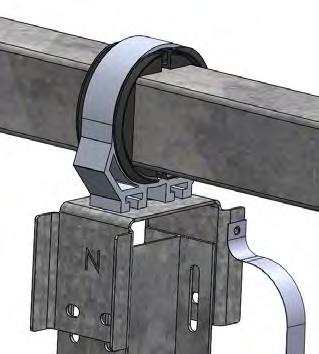
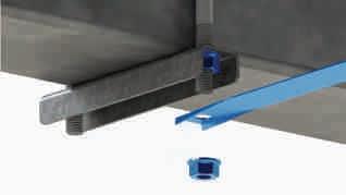

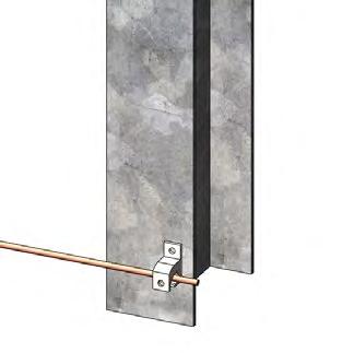
12.4
Bonding Adjacent Tables (View D)
12.4.1 Place the Braided Jumper on top of the serrated flange nut already installed on the U-bolt or Thrubolt at the end of the table and parallel with the Purlin Channel of a nearby SpeedClamp or Purlin assembly. Secure in place with a second serrated flange nut and torque to specification.
12.4.2 Make sure the Braided Jumper is routed from the last Purlin Channel on one table to the first Purlin Channel on the next table in such a way as to avoid sharp bends / cracking. Also, make sure the Braided Jumper is curved so that 10” [254 mm] of slack exists between the two connections.
12.4.3 Attach the other end of the Braided Jumper on top of the serrated flange nut already installed on the U-bolt or Thru-bolt of a nearby SpeedClamp or Purlin assembly. at the end of the adjacent table. Secure in place using a second serrated flange nut. Torque to 10 ft-lbs (13.5 Nm).
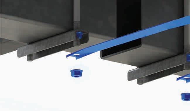

TABLE 1 TABLE 2 TABLE 3
Grounding Through Adjacent Tables
Grounding at Each Table
Example showing either grounding through adjacent tables or grounding at each table
Step 13: Module Installation
13.1 Check the install manual for the module you are installing to make sure that the mounting hardware and installation methodology recommended by GameChange mentioned below is acceptable. Certain modules may require the use of grounding straps instead of star bolts for high wind or snow loads. Otherwise you may risk voiding the warranty for your modules. It is also recommended to check that the modules are listed per UL 1703.
13.2 It is the customer’s responsibility to follow module spacing guidelines provided by module manufacturer in their specification sheet or elsewhere, otherwise module warranty could be voided. In all cases make sure module spacing is the greater of ¼” [3 mm] or the minimum called out by the module vendor. This will allow for thermal expansion of modules. GameChange Solar Genius Tracker systems typically enable 1/2” [12 mm] module spacing if aligned properly.
13.2.1 Spacing between modules can be set by placing a temporary spacer such as bolt shaft or plywood of same thickness as required for module spacing between modules while they are being installed. This spacer shall be removed after module installation is complete.

13.3 Unless Prohibited by module manufacturer, for portrait configuration place modules such that junction box is on the west side of the module. Run string wires on west side of Row Tubes.
13.4 This is a generic manual, showing the multiple mounting options below. Please reference Project Construction Drawings for specific mounting method to be used for the site.
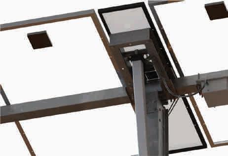

13.5 Install Purlin Strips at all module mounting locations where the Purlin is only fastened to one module. These locations include at the Charging Module, the ends of Tracker tables, and CAB/BOS gaps (if applicable). A Purlin strip is required at each location where a bolt connects the PV module frame to the purlin.
13.6 Mount the Purlin Strip using 2x 1/4” flange bolts and nuts. Mount the PV module on top of the Purlin Strip and Purlin such that the Purlin extends beyond the module frame so there are no obstructions behind the module. Torque to spec.
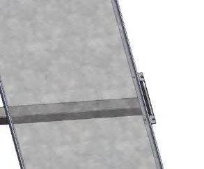
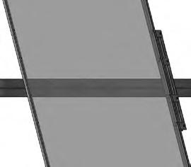
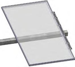
13.7 Install PV modules onto Purlins using serrated flange bolts and nuts, spacing Purlins appropriately. One of the bolts used to mount each PV module must include a star bolt on the inside of the module frame to bond the module to the system.
13.8 Attach with a hex bolt inside the module and serrated flange nut outside the Purlin. Torque module hardware and Purlin Thru bolts to specification.
13.9 Place modules such that junction box is on the west side of the module. Run string wires on the west side of the Row Tube.
13.10 Make sure that there is at least 1/2” (13 mm) of Row Tube overhang after installing the Purlin. Measure from the end of the Row Tube to the end of the Purlin as shown below.
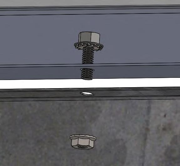
Min edge distance of 1/2 inch (13mm)

Step 14: Mounting the Master Controller
Step 14.1: Installing the Master Controller Pole
Install Master Pole and associated components in a position where no shading is cast on the arrays.
The Master pole shall either be installed in concrete or onto a spare post. Master Pole must reach a minimum height of 17’-0” (5.1816 m) above ground.
Master Poles are installed at a minimum of 10 feet (3 m) away from the inverter (see Master Controller Layout sheet for pole locations). Master Unit must also have a clear line of sight to the arrays that it controls (one Master Unit can control around 200 to 250 nodes). Be sure that no obstacles (such as inverters) are in between the Master Unit and its controllers.
Step 14.1.1: Mounting a Master Pole in a Concrete Pier
14.1.1.1 Install Master Pole at location as shown in Project Construction Drawings. Master Unit needs clear line of sight to Node Controllers it will communicate with. Be sure that no obstacles (such as inverters or transformers) are between the Master Unit and its Node Controllers. Notify GameChange technical staff immediately if Master Pole location shown does not provide line of sight to Node Controllers.
14.1.1.2 Master Pole shall be installed in concrete pier as follows:
14.1.1.2.1 Drill a 6” (15 cm) diameter hole at least as deep as the minimum embedment depth of the shallowest standard post on the site.
14.1.1.2.2 Place the Master Pole in the hole such that the minimum stickup of the pole is at least 17‘-0” [5.1816 m]
14.1.1.2.3 Temporarily shore (support) the Master Pole so it is within 1 degree of plumb
14.1.1.2.4 Pour concrete into the hole to secure the Master Pole in place. The concrete shall meet the following specifications:
• Min compressive strength of 4000 psi [27.5 MPa]
• Max aggregate size of 3/8” [9 mm]
• Slump of 5 inches [127 mm] or less
• Air content (air entrainment) of between 6% or 8%
• Max water to cement ratio of 0.45
• Admixtures may be used but they shall not contain chlorides or calcium chlorides.
14.1.1.2.5 Wait at least a day for the concrete to cure before removing shoring.
Minimum 17 ft [5.1816 m] above ground level
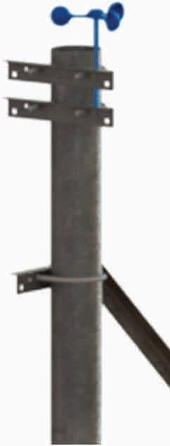
Step 14.1.2: Mounting to a Spare Post
Drive post to an embedment greater than or equal to the minimum embedment for the interior standard posts shown in the Project Construction Drawings.
Master Pole is attached to a spare tracker post by field locating and drilling four 1/2” (13 mm) diameter holes in the post per the dimensions on Detail A. Use two U Bolts and four flange nuts to attach the post to the Master Pole.
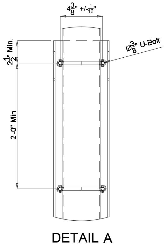

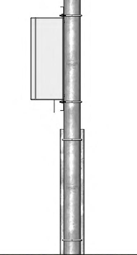
Step 14.2: Mounting the Master Controller Module
NOTE: The front of the Master controller module shall have clear line of sight to the Nodes that it will be controlling.
14.2.1 Place one Master Pole Angle on top of Master Controller and place one Master Pole Angle on bottom of Master Controller.
14.2.2 Attach Master Pole Angles to Master Controller using 1/4-20 hex bolts and serrated flange nuts. Torque to specification.
14.2.3 Use two Pole U Bolts and four flange nuts to attach Master Controller with Master Pole Angles onto Master Pole. Torque to specification. Bottom of enclosure shall be 3’ [0.914 m] to 4.5’ [1.371 m] from the ground.
Step 14.3: AC Power Connection
It is required to connect the Master Unit to line power. Line power shall be 110V-220V AC (nominal) and the power lines shall be rated for at least a 2 amp draw from the Master Unit. Connect the Line, Neutral, and Ground wires to the 3 prong pigtail coming from the Master Unit enclosure using an outdoor rated 3 prong connector.
14.3.1 Line power 110V-220V AC is required for the operation of the Master Controller and RSU.
14.3.2 The GCS Master Controller is supplied with a cable with a 3-prong American Standard NEMA 5/15P plug intended for connection to a standard US outlet, which must be grounded. Ensure the connection is made weatherproof.
If a permanent installation is preferred, the cable may be cut to remove the AC plug. The wire colors are black (LINE), white (NEUTRAL), and green (PROTECTIVE EARTH). The green earthing conductor must be grounded and the installation must comply with UL 61010: Permanently connected equipment shall employ a switch or circuit-breaker as the means for disconnection. The switch or circuit-breaker shall be in close proximity to the Master Controller and within easy reach, and it shall be marked as the disconnecting device for the equipment. The switch or circuitbreaker shall meet the relevant requirements of IEC 60947-1 and IEC 60947-3. The switch shall not be incorporated in a MAINS supply cord and shall not interrupt the protective earth conductor. Moreover, the wiring system must be made in accordance with ANSI/NFPA 70, NEC, with CSA C22.1, CEC, Part I or with both as appropriate. Bonding and all parts of the supply circuit must be rated for at least twice the fused AC current in the Master Controller.
Step 14.4: Network Cable Connection
The Master Controller is equipped with 1” or 1/2” (25.4 mm or 12.7 mm) diameter conduits to enable connectivity for a data acquisition system.
The network cables can be either RJ-45 Ethernet, or SFP fiber optic transcievers, depending on the type of Managed Ethernet Switch installed in the Master Controller.
14.4.1 Replace the factory installed conduit plug and attach a matching conduit system that complies to UL514B and maintains the NEMA 4X rating of the enclosure.
14.4.2 Ethernet cables shall be shielded and must not exceed 90ft for EMC compliance.
14.4.3 To prevent ingress of rodents, insects or water/ humidity into the Master Controller, the conduit may be sealed using a polyurethane foam product rated for use with outdoor electrical conduit.
If the GeniusHub operator console is in use, the network cable should be run directly to the managed network switch in the GeniusHub rackmount cabinet. Otherwise, connect the Master Controller to plant SCADA.

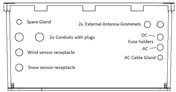
Bottom of the Master enclosure


Step 14.5: Master Controller Battery Installation
NOTE: Master Controllers may be shipped with the battery preinstalled. If this is the case, you may skip the installation instructions.
Tools Required:
• Calibrated Multimeter
• Non-Contact Voltage Detector (NCV)
• Philips Screwdriver
• Flathead Screwdriver
• Ratchet with 10mm socket
• GCS node controller part number 357783
Battery Installation
14.5.1 Locate and open Master Controller Unit’s (MCU) door. Pull the top and bottom latch to open the door.
14.5.2 Visually verify that PCB’s LED are ON and blinking. Note the zone’s tracking state to ensure that it resume tracking state after installation.
14.5.3 Take inside photos of the Master Controller Unit. The photo can be used as a wiring reference later in case any of existing wiring gets disturbed. See Photo A.
14.5.4 De-energize MCU by unscrewing the AC and DC fuse holders at the bottom of the enclosure using a flathead screwdriver. See Photo B.
Note:
• Make sure to secure the fuse holders and fuses in a safe location to avoid potential damage and misplacement.
• If the Master Controller is de-energized for more than two hours, the zone will automatically stop tracking and the tables will be moved into a stowed position.
14.5.5 Verify MCU is de-energized by first visually verifying PCB, Ethernet Switch, Pi/Libre and modem’s LEDs are off. Second, use a non-contact voltage detector or multimeter to verify MCU power is completely off. Use the multimeter to check power supply’s output. See Photo C.
I Warning! Use caution as MCU is not completely deenergized. Incoming power service is still live but isolated by the terminal block at the bottom of the enclosure. See Photo D.
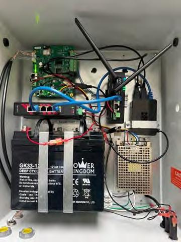
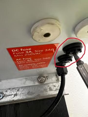

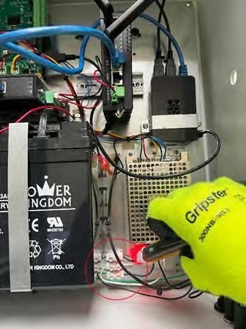
I Unscrew the top bracket’s screws (see Photo E) to allow the battery to tilt forward. Use the other hand to support the battery if needed. See Photo H.
14.5.6 Use ratchet with 10mm socket to loosen up the bolt head. Start by loosing up the negative (black terminal) bolt first and then positive (red terminal) bolt. Make sure to tilt the battery forward to allow socket to fit. See Photo F. As a tip, continue loosening the bolts with your fingers instead of the ratchet to make the process easier. See Photo G.
14.5.7 Install the new battery in place. Use the battery guide slots (metal pieces protruding out from the back panel) to support the weight of the battery. See Photo H.

14.5.8 Hand screw the bolts into the battery terminal. Start with the positive bolt terminal (red) and then connect the negative bolt terminal (black). See Photo G. Finish by tightening the bolts using the 10mm socket rachet.
14.5.9 Secure the battery by tightening the brackets’ screw to the back panel.
14.5.10 Measure initial battery’s voltage using a multimeter as a reference before and after energization.
14.5.11 Install the fuse holders back in place. See Photo B.
14.5.12 Verify that PCB’s LED are back ON and blinking.
14.5.13 Finally, measure the battery’s voltage again using the multimeter after energization. There should be an increase of voltage before and after the energization if installation is correct. Voltage difference would depend on the state of charge of the battery. See Photo I.
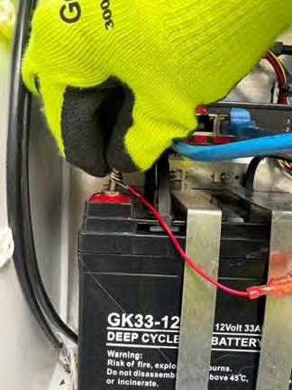
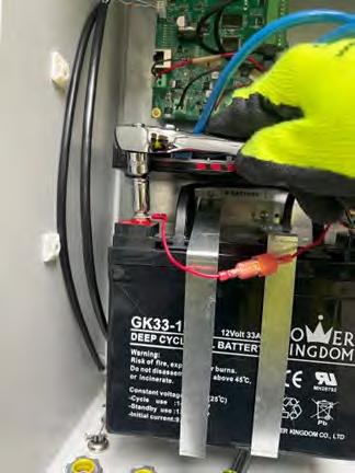

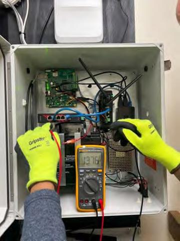
Step 14.6: Mounting the Anemometer
14.6.1
Wind Sensor Cable Assembly
Attach anemometer at top of Pole using Pole Angles. Use hardware provided with Anemometer to attach anemometer to Pole Angle. Use Pole U Bolt and two flange nuts to attach Pole Angle onto top of Pole.
Torque to specification.
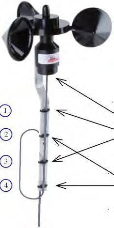
*Caution: Do not excessively tighten cable between sensor and 1st cable tie*
Open the sensor housing
Remove existing wiring and grommet
Increase sensor housing hole size to 21/64"
Install grommet and cable
Peel wires and install in terminal block
Lock the cable to the aluminum holder with cable ties
Loop Cat5 cable through 2nd & 4th cable tie (1 pass)
Grommet 0.219"
2x Cable-Tie
Cable Loop Dia. ~10"
2x Cable-Tie (On Looped wire Only)
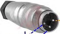
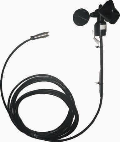
Step 14.7: Mounting the Snow/Flood Sensor (Optional)
14.7.1 Snow/Flood Sensor is only required in some areas prone to extreme snow or flooding. Please consult GameChange if your System requires Snow/Flood Sensor(s).
14.7.1.1 Make sure each Snow/Flood Sensor is installed above a level area where no vegetation can grow and cause false readings (see 14.7.3).
14.7.1.2 Install Snow/Flood Sensor onto Yardarm using two #14-10 sheet metal screws, and attach other end of Yardarm onto pole using a Pole U Bolt and 3/8-16 serrated flange nuts,torque to specification.
14.7.1.3 Position Snow/Flood Sensor away from the Master Controller.
14.7.1.4 Attach the Yardarm to the pole supporting the Master Controller approximately 4’-0” above grade.
14.7.1.5 Level Yardarm so that Snow/Flood Sensor is pointing directly down. It is important that the snow sensor is pointing perpendicular to the ground.
14.7.1.6 Install Pole Angle (above) and Yardarm (below) to Master Pole using Master Pole U Bolts and 3/8-16 serrated flange nuts. Install Yardarm Support onto Pole Angle and Yardarm using 3/8-16 hex bolts and serrated flange nuts. Ensure Yardarm is level. Torque to specification.
14.7.2 If flood/snow sensors are required, do not install Master Pole on a concrete inverter pad. Master Poles supporting flood sensors shall be installed at a location with a grade elevation no higher than 6” (15 cm) below the design flood elevation for the zone controlled by the Master Controller on that Pole.
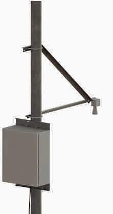

Snow/Flood Sensor Cable Assembly
Snow/Flood Sensor only if provided

14.7.3 Ensure the area under the snow sensor is treated to keep it level and free of vegetation
• The area to keep clear is a 6ft (1.8 m) diameter circle centered under the snow/flood sensor
• It is important this area is level, this can be accomplished by distributing gravel or other filler material
• It is crucial to keep this area free from vegetation as this will be detected by the sensor. This can be accomplished by adding a sand barrier under the gravel, using landscape fabric or plastic barrier, or by regularly weeding the area.
• It is recommended to install a concrete slab or gravel below the flood sensor to prevent vegetation from triggering the sensor. The top of the concrete slab or gravel shall be at the same elevation as the adjacent soil.
14.7.4 Use UV-resistant cable ties to secure wires tightly every twelve inches along their runs. Avoid any sharp edges that may cause chafing of wires.
Notes on Operating Snow/Flood Sensors
! If Snow/Flood Sensors are deployed on system, please note that Snow/Flood Sensors must be properly maintained and calibrated or they could cause false positives or negatives which could adversely affect production and damage the system.
! Also, snow sensors are not to be solely relied upon to protect against snow storms.
! After snow events of over 6 inches [152 mm] of snow, the modules must be cleared and the area under modules where they rotate to at maximum rotation must be cleared or modules and other components of the system could be broken as they are driven into snow banks. Once all clearing is completed, Snow/ Flood Sensor area must be cleared or Snow/Flood Sensor level reset (tare) to reactivate system tracking and prevent production loss. See Genius Tracker O&M Manual for more information
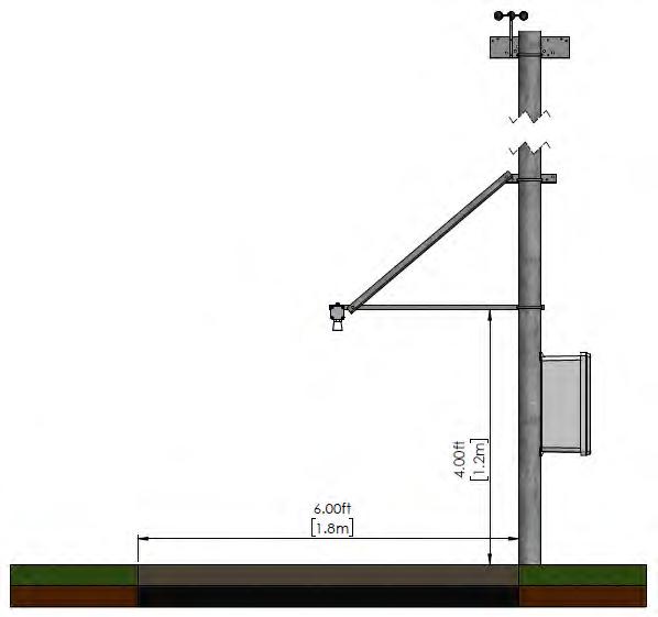
Step 15: Wire Management for String Wires
15.1 The Genius Tracker system will constantly have the modules and the Row Tubes rotating across a large range of motion. It is important that wiring must have substantial slack built in at all points
15.1.1 Where row ends meet each other make sure that all wires are pulled in to the Row Tube as they transition to the next Row Tube.
15.1.2 Make sure to have at least 1’ [0.305 m] of slack in addition to the distance between the ends of the Row Tubes where jumping wires between tables.
15.1.3 Wires going over the Driving Arm must also have at least 1’ [0.305 m] of slack such that the rotating movement of the Driving Arm and Row Tube does not pull or cut the wire.
15.1.4 Module String Wiring must be on WEST side of table.
! SUGGESTED MEANS & METHODS
15.1 Module Wiring

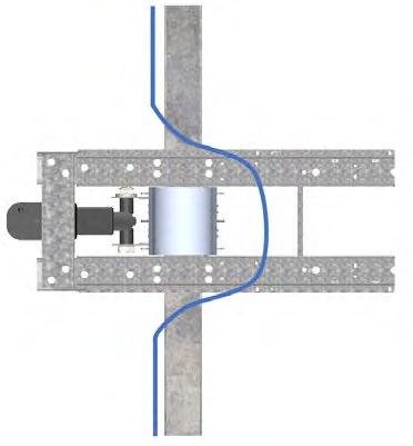
15.1.1 The Genius Tracker allows for wires to be cable tied along the entire length of the Row Tubes under the Row Tubes.
15.1.2 Installer standard practice is to run wires along the modules at the level of the junction boxes and clip wires to the module frames.
15.1.3 Wire management holes are typically pre-punched in the Purlins for First Solar Series 4 modules to allow easier wire management along the purlin direction.
15.2 All wiring mounted to the Row Tube, Modules, or Module attachment must be run on the WEST side of the table.
15.3 For homerun wires and other conductors carrying more than 50 amps, some installers have opted to hang these wires from the tracker structure utilizing fully insulated wire management cable clips such as the 100% coated round wire, made by CAB.
15.4 If there may be animals that could chew on the wires running from the Actuator or any other wires, make sure to protect the wires with appropriate armoring.
X SYSTEM SPECIFICATIONS (NODE)
Node Controller
Physical dimensions
Operating temperature
Storage temperature
Electrical input and output voltage and currents
Battery type, size, voltage, amp hour rating
Communication protocol, frequency
Maximum operational load
Fuse rating and type
Master Controller
Physical dimensions and weight
Operating temperature
Storage temperature
Master Controller Electrical input and output voltage and currents
DC Fuse rating and type
AC Fuse rating and type
Battery type, size, voltage, amp hour rating
General System
Product Use
Altitude
Operating temperature
Maximum Relative Humidity
MAINS Supply Voltage Fluctuations
Overvoltage Category
Pollution Category
13.58 x 9.28 x 6.25 inches [345 x 236 x 159 mm]
-20°C (-30°C also available) to +48°C, outdoor
-30°C (for 50%+ SOC) to +60°C, indoor
Input 36-50 V DC from solar module. Controller draws < 2 A.
Output 24 V DC motor output. Max 15A.
VRLA, 24 V DC, 8 Ah
Wireless 2.4 GHz LwMesh mesh
7400 lbs [3356.6 kg]
15A, size 3AG (1.25” x 0.25” cartridge type),
min 125 V AC/ 30 V DC
19.3 x 17.3 x 9.6 inches [490 x 440 x 245 mm], 45.8 lbs [20.7 kg]
-20°C (-30°C also available) to +48°C, outdoor
-30°C (for 50%+ SOC) to +60°C, indoor
Input 90-264 V AC single-phase.
Current draw at 120 V AC: 100 mA typical, 500 mA max.
3 A, size 3AG (1.25” x 0.25” cartridge type), min 250 V AC
3 A, size 3AG (1.25” x 0.25” cartridge type), min 250 V AC
VRLA, 12 V DC, 35 Ah, 7.7 x 5.1 x 6.6 inches [196 x 131 x 167 mm]
Outdoor Use
Up to 2000m (For Projects Located in Canada)
-20°C (-30°C also available) to +48°C, outdoor
80% for temperatures up to 31°C; decreasing linearly to 50% relative humidity at 40°C
90V – 264V
II (For Projects Located in Canada)
2 (For Projects Located in Canada)
XI DECOMMISSIONING GUIDELINES
At GameChange Solar, our mission is to repower the planet with clean solar energy. That mission continues at the end of a solar power installation’s service life. It then becomes our mission to ensure that the components of the system are reused and recycled to the greatest extent possible, Recycling provides a number of benefits:
• Minimises environmental impact by diverting waste away from landfills and incinerators
• Provides raw materials for new projects and improvements
• Reduces the use of unspoiled natural resources
• Saves energy
• Frees up land for reuse
• Recovers as much of the remaining value of the system as possible for our customers
We recommend that system components be disassembled and recycled according to the following guidelines.
Disconnection from the Power Grid
At the end of its service life, the Genius Tracker installation shall be disconnected from the power grid.
Recycling Copper Wiring
Copper wiring has a high value and is highly recyclable. Immediately upon end of service, all copper wiring shall be removed from structure, conduits and underground channels, collected, and stored in a secure location for recycling.
Fiber Optic Reuse and Recycling
Fiber optic cables used for communications in a solar power plant should also be collected and stored in a secure location at the end of service.
Fiber optic cables can be reused, donated for reuse, or scrapped and recycled by specialized firms.
Recycling Steel Structural Components
At the end of the useful life of the system unbolt PV modules and structural components. Driven posts may be pulled or dug out of the ground using a gradeall (lull), excavator, or similar equipment.
It is recommended to send steel components to a scrap yard where they can be melted down and recycled.
Battery Recycling
Both the Node Controller and the Master Controller use lead-acid gel batteries that are almost 100% recyclable. They can be recycled using standard automotive/marine battery services.
Batteries should be removed from the controllers, palletized, and stored in a secure location for pickup by recycling services

PV Module Reuse and Recycling
Photovoltaic modules can be used in a number of ways at the end of their service life:
• Modules may be kept intact and repurposed in less demanding roles.
• Modules may be sold on the secondhand market.
• Modules may be donated to charitable organizations.
• Modules can be recycled to serve as raw materials.
Site Remediation and Cleanup
All electrical power components such as inverter, transformers, and associated equipment and shelters shall be removed and recycled off-site.
All unwanted concrete will be removed and recyled off-site. Perimeter fences, landscaping, and security systems may be left in place as desired.
A APPENDIX FOR APPROVED MODULES – DIRECT MOUNT
To be used only in combination with the modules that include this specific rack system in the module manufacturer’s installation manual. The following modules have been evaluated for grounding and bonding only per the UL 2703 standard.
MANUFACTURER MODEL(S), WHERE “XXX” IS THE MODULE POWER RATING
Adani
Astronergy
Boviet
ASP-7-aaa where “aaa” = 300 - 330
ASB-M10-144-XXX
CHSM66M-HC, CHSM72M-HC, CHSM66M(DG)/F-BH, CHSM72M(DG)/F-BH, CHSM78M(DG)/F-BH, CHSM66N(DG)/F-BH, CHSM72N(DG)/F-BH, CHSM78N(DG)/F-BH, CHSM72RN(DG)F-BH
BVMaaaaM-XXXY-ZZ Where “aaaa” can be 6612 or 7612, where “Y” can be S or L, where ZZ can be H, H-HC, H-BF, H-BF-DG, H-HCBF, or H-HC-BF-DG.
BYD BYD P6C-36 Series 3BB, BYD MLTK Series, BYD MSTK Series, BYD NLTK-36 serials, BYD NLBK-36 series
Canadian Solar CSbY-ZZ-WW where “bY” can be 3U, 3W, 3Y, 6P, 6W, 6X, 7L, or 7N; where “ZZ” can be P, PB, MB, MS, TB or blank; where “WW” can be AG or blank.
ET Solar ET-P67-WW/WB, ET-M772BHxxxYY Where “YY” can be TW or TB.
EMMVEE ExxxHCBG144
First Solar First Solar Series 6, Series 7.
GCL Solar GCL M3/72DH
Hansol HSxxx-YY-AN3 where “YY” can be TD or TB
Hanwha Q-Cells Q.YY-ZZ-xxx where “YY” can be PLUS, PEAK, PLUS DUO, or PEAK DUO; “ZZ” can be L-G4.1, or L-G4.2, L-G5.X, L-G6.X, L-G7.X, L-G8.X, L-G8.3/BFF, L-G8.3/BFG/BGT, XLG9, XL-G9.2, XL-G9.3, XL-G9.3/BFG/BGT, XL-G10, XL-G10.2, XL-G10.3, XL-G10.3/BFG/ BGT, XL-G11.2, XL-G11.3, XL-G11.3/BFG, XLG11S.3/BFG, Q.TRON XL-G12.3/BFG
Heliene HSPE-144HC-Maa Where “aa” can be 10 or 6.
HT-SAAE
HT72-aaaY Where “aaa” can be 156, 166, or 18; where “Y” can be M, M(V), or X.
Hyundai HiS-YxxxRi where “Y” can be M or S
Hyperion HY-DH144P8-XXX
JA solar JAXYaaSxxZZZ where “X” can be P, or M; “Y” can be 6, 7, 6(k)-, or blank; “aa” can be 60 or 72; “Sxx” can be blank, S01, S09, S10, S30, or D30; where “ZZZ” can be /MR, /MB, or blank.
Jinko JKMxxxX-aaYYb-ZZ Where “aa” can be 72 or 7; where “X” can be M or N; “YY” can be HL or RL; where “b” can be 3, 4, or blank, where “ZZ” can be V, BDV or TV.
Longi LR4-72HBD, LR5-72YYY-xxxM
Where “YYY” can be HBD, HPH, or HGD. LR6-YYZZ where “YY” can be 60, or 72; “ZZ” can be PD, PH, PE, BP, PB, HV, HPD, or HPH.
Maxeon SPR-Pa-XXX-UPP Where “a” can be 5 or 6.
Mission Solar MSExxxSQ9S where “xxx” = 365 - 375
NE Solar NESE-72MH-M6, NESE-72MHB-M6, NESE72MH-M10, NESE- 72MHB-M10, NESE54MH-M10
MANUFACTURER
MODEL(S), WHERE “XXX” IS THE MODULE POWER RATING
Philadelphia PS-M144(HCBF)-xxxW, PS-M144(HCBF)GG-xxxW.
Phono Solar PS380M-24/TH REC RECxxxTP2SM 72
Risen Solar RSM72-6-aaaP, RSM72-6-aaaM, RSM1108-XXXM, RSM110-8- XXXBMDG, RSM1208-XXXM, RSM120-8-XXXBMDG, RSM150-8XXXM, RSM150-8-XXXBMDG
Seraphim
SEG
SRP-xxx-6YZ where “Y” can be P, Q or M; “Z” can be A or B.
SEG-aXX-YYY-BG
Where “a” can be 4, 5, or 6; where “YYY” can be BMA, BMB, or BMC.
Silfab SIL-490-HN
Talesun
TD6I72M, TD7G78M, TD7G72M, TP7F78M, TP7F72M, TP6L72M
Trina TSM-aaaYYZZ where “aaa” can be PA, PD, DEG, DE, or NEG; “YY” can be 05, 14, 15, 19, 20, or 21; “ZZ” can be blank, C.20, VC.20(II), HC.20(II), .05, or RC.20.
Vikram PREXOS VSMDHT.72.XXX.05 VSUN VSUNXXX-144YYY-ZZ
Where “YYY” can be BMH, MH, M, BH, or M; where “ZZ” can be DG, BW, BB, or be blank.
Yingli YLXXXYY72 1/2
ZNShine
Where “YY” can be DL or DF.
ZXM6-NH144-XXX/M, ZXM6-NHDB144XXX/M, ZXM6-NHLDD144- XXX/M, ZXM7SHDB144-XX/M, ZXM7-SHLDD144-XXX/M, ZXM7-SH144- XXX/M
B APPENDIX FOR SPEEDCLAMP™
The GC4318 SpeedClamp™ is a clamp assembly that can be used to mount PV modules onto GameChange Solar Genius Tracker™ Systems.
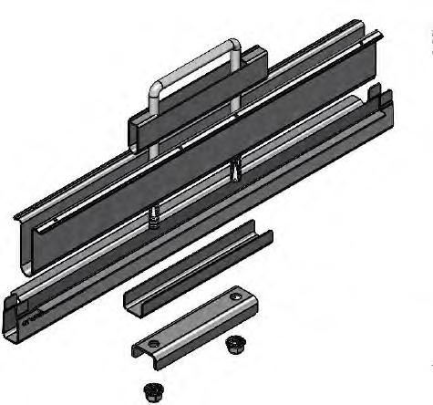
Tools Required:
Rated wrenches and driver sockets, both standard and deep, in the following size(s):
• 9/16 (for 3/8-inch flange nuts)
System Components:


Associated Hardware:
• 3/8-16 x 4 inch wide U-Bolt – magnicoat (1)
• 3/8-16 serrated flange nuts – magnicoat (2)


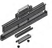
Installation of Assembly
Step B1: Preassembly of SpeedClamp™
! SUGGESTED MEANS & METHODS
1.0 Preassembly option available for SpeedClamp™. If SpeedClamp™ is not preassembled, it is recommended that each set of SpeedClamp™ are preassembled for quicker deployment.
1.1 The stackup order of parts from top to bottom are:
• 3/8-16 x 4”ID U-bolt
• GC4318-CX – SpeedClamp™ Channel
• GC4318-A – SpeedClamp™ Top
• GC4318-B – SpeedClamp™ Bottom
• GC4378W-.38 – Reinforcement Channel (if provided)
• GC378BU-.38 – Purlin Channel
• 3/8-16 serrated flange nuts

1.2 Keep the serrated flange nut flush with the end of the U-bolt.
Step B2: Position SpeedClamp™ onto Row Tube
1.0 Position appropriate number of SpeedClamp™ along Row Tube depending on the module size and configuration shown on the Project Construction Drawing. A SpeedClamp™ is required at every panel edge.
1.1 Take preassembled SpeedClamp™ and pre-position along a Row Tube by loosening the flange nuts enough that the space between the SpeedClamp™ Bottom (or Reinforcement Channel if provided) and Purlin Channel is larger than the Row Tube, and sliding the appropriate number of assemblies onto the Row Tube at the approximate locations they will be needed.
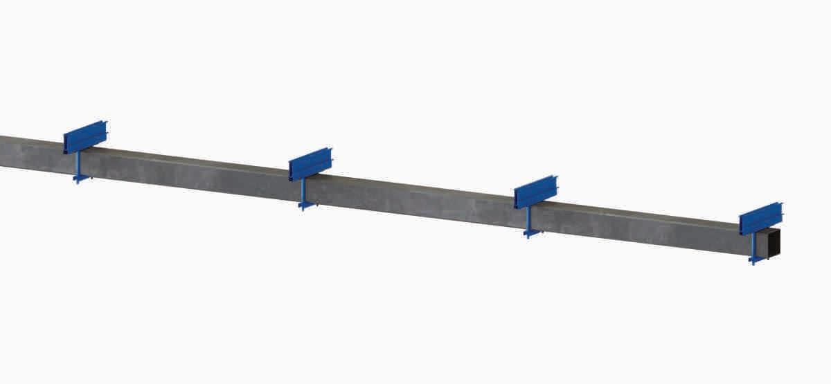

Step B3: Module Installation onto SpeedClamp™
1.0 Rotate table flat for module installation. Rotate table back to stow once modules are installed.
I DO NOT under any circumstance exceed 25 degrees east rotation. Only rotate tables with GCS Rotator Harness.
1.1 Leave SpeedClamp™ loose enough to insert module frame in between the SpeedClamp™ Top and SpeedClamp™ Bottom. Slide a module frame edge into one side of SpeedClamp™. Use tolerance of 1/2” for east-west centering of module on clamp. Center the module East-West relative to the SpeedClamp™. Ensure module frame is butted up against the wall of the SpeedClamp™ top for the full length of the SpeedClamp™
! Avoid “stair stepping” of modules, top and bottom edges should align.
1.2 If SpeedClamp™ will hold two modules (being used as mid clamp), slide other module frame into other side of SpeedClamp™. Center the module East-West relative to the SpeedClamp™. Ensure module frames are butted up against the wall of the SpeedClamp™. Top for the full length of the SpeedClamp™. Torque to spec per Module Installation Section of Project Construction Drawings. Torque shall not be less than 6 ft-lbs (8.1 Nm).
I DO NOT OVERTORQUE.
1.3 If SpeedClamp™ will only hold one module (being used as end clamp), slide End Clamp Insert into other side of SpeedClamp™ such that the prongs are inserted into the SpeedClamp™ Bottom. Center the End Clamp Insert East-West relative to the SpeedClamp™.
Ensure module frame is butted up against the wall of the SpeedClamp™. Top for the full length of the SpeedClamp™. Torque to spec per Module Installation Section of Project Construction Drawings. Torque shall not be less than 6 ft-lbs (8.1 Nm).
1.4 DO NOT OVERTORQUE.
! Run first nut up to the GC4378BU so that it is tightly against the tube, then repeat for other side. Then go back to first side and torque to spec, then repeat for other side.
1.5 Module frames must be placed up against the wall of the SpeedClamp™. The maximum gap allowed between the frame and SpeedClamp™ wall is 1/16” [1.5 mm].
1.6 Repeat until all panels are installed on table.
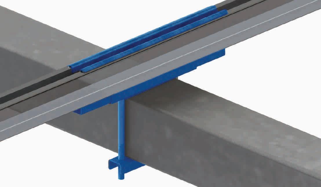


1.7 When setting up SpeedClamp™ onto the Row Tube (Step B3.2), SpeedClamp™ assemblies may also be positioned on a Row Tube by undoing the flange nuts and Purlin Channel, positioning the U-bolt around the Row Tube, then reinstalling the Purlin Channel and flange nuts.
NOTE: SpeedClamp™ must be vertical on the Row Tube (within 1 degree of plumbness).
1.8 Make sure that there is at least 1/2” of Row Tube overhang after installing the SpeedClamp. Measure from the end of the Row Tube to the edge of the SpeedClamp as shown below.
I Check the panel install manual for the module you are installing to make sure that the panel mounting hardware and installation methodology recommended by GameChange mentioned above is acceptable. Otherwise you may risk voiding the warranty for your modules. It is also recommended to check that the panels are listed per UL 1703.
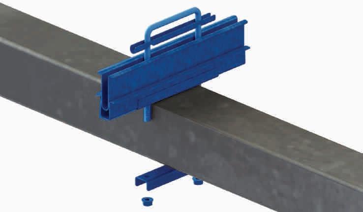
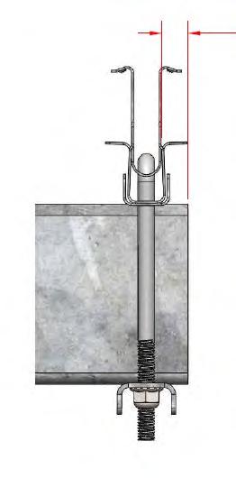
Additional System Components for First Solar Series 6
End Clamp (GC316) Shared Clamp (GC317) T-Bolt (GC1305)
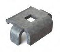
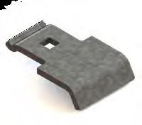

Step C1: GC316 – End Clamp
1.0 Position Series 6 module next to mounting hole.
2.0 Place End Clamp FSLR6 through slot of Series 6 module frame with hole lining up with mounting hole.
3.0 Drop GC1305 T-bolt through square hole in End Clamp FSLR6 and mounting hole.
4.0 Screw on serrated flange nut to capture joint, rotate GC1305 T-bolt to lock orientation against module, and torque to 11.75 to 12.25 ftlbs (15.93 to 16.60 Nm).
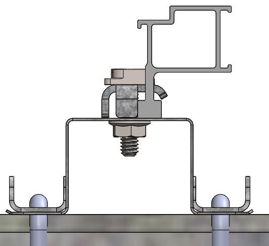
Step C2: Shared Clamp FSLR6
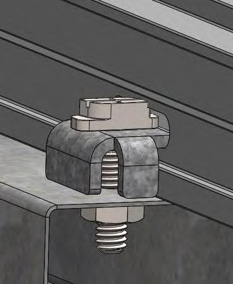
1.0 Position first Series 6 module next to mounting hole.
2.0 Place Shared Clamp FSLR6 through slot of first Series 6 module frame with hole lining up with mounting hole.
3.0 Drop GC1305 T-bolt through square hole in Shared Clamp FSLR6 and mounting hole. (Loosely screw on serrated flange nut to capture joint.)
4.0 Slide second Series 6 module under free end of Shared Clamp FSLR6. Guide feature will aid in passing free end of Shared Clamp FSLR6 through slot of second module. Shared Clamp FSLR6 or GC1305 T-bolt may need to be held to maintain orientation as second module is situated.
5.0 Rotate GC1305 T-bolt until orientation is locked between modules, and torque to 11.75 to 12.25 ft-lbs.

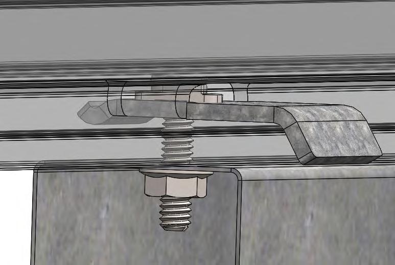
D APPENDIX FOR INSTALLING FIRST SOLAR SERIES 7 MODULES TO ROW TUBE
1.0 Position the Purlins on the Row Tub such that they are in line with the long-side mounting rails and insert the rails into the Purlins. After the Purlins and Module frames are spaced out correctly (both at the Charging Module and relative to adjacent Modules), torque the 3/8" thru-bolt to specification (28-31 ft-lbs)[38-42 Nm].
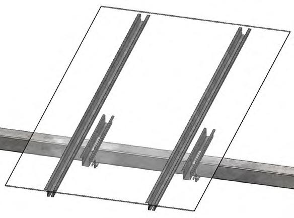

2.0 Secure Series 7 modules to purlins using PowAR Wedges in accordance with wedge manufacturer instructions. Note design of Server 7 module to purlin connection using PowAR Wedges by others.
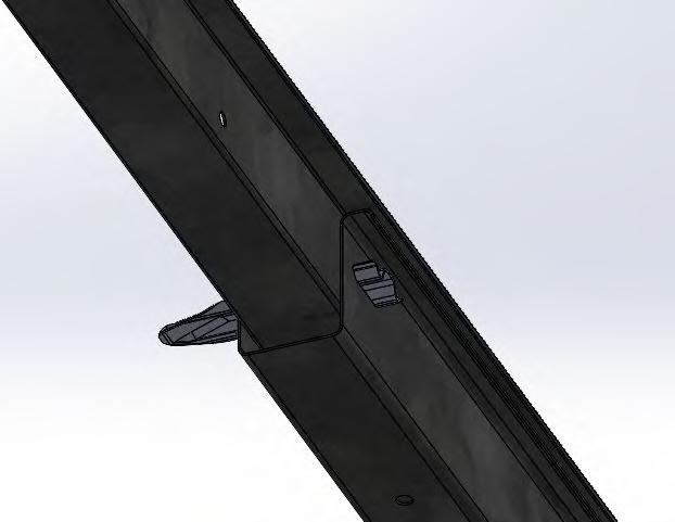
3.0 Check the panel install manual for the module you are installing to make sure that the panel mounting hardware and installation methodology recommended by GameChange mentioned above is acceptable. Otherwise you may risk voiding the warranty for your modules. It is recommended to check that the panels are listed per UL 1703.
4.0 Rotate table flat for module installation. Rotate table back to stow once modules are installed.
NOTE: Tables shall be left in stow when not being actively worked on prior to commissioning. For ease of panelization or wire installation, table may be temporarily rotated up to 25 degrees East position while wind speed is under 22 mph [10 m/s]. Table shall be rotated back to stow when not actively being installed.
E APPENDIX FOR 2-PIECE BEARING
Additional System Components for 2-Piece Bearing Assembly
Bearing Bottom (GC6601)


Bearing Top (GC6602)


Standard Bearing Wheel (GC6367) used in pairs

Capture Plate (GC6603AD) used in pairs

(GC6603) Alternate

Associated Hardware:
For installing each Capture Plate onto Bearing Collar:
• 1/4-14 x 3/4 inch serrated head TEK screws – magnicoat (or SS) (3)
Step E1: Bearing Installation
1.0 Bearing Assembly for Standard Wide Flange Post:
1.1 If using preassembled SpeedClamps or preassembled Purlins, place the appropriate number of SpeedClamps or Purlins along the Row Tube prior to installation of the Bearing Assemblies.

1.2 Place Row Tube into Bearing Wheel halves. Then place Bearing Wheel halves onto Bearing Bottoms.
Bearing Assemblies shall be within ± 0.1% alignment with Row Tube.
1.3 Place Bearing Wheel halves on top of Row Tube Note: Bearing Wheel halves shall be above and below the Row Tube for installation. After Driving Arm Installation, Bearing Wheels shall be vertical (side to side) when Driving Arm is Horizontal.
1.4 Bearing Top shall be placed around Row Tube, then slid over Bearing Wheel halves in line with the Bearing Bottom.
1.5 Capture Rings (one on each side of the Bearing Collar) shall be attached via TEK screw onto the Bearing Bottom (x2) and Bearing Top (x4).
1.6 Bearings have substantial vertical (up to 2-1/2") [63 mm] as well as lateral flexibility to allow for ease of installation. The bearing assembly also provides up to 1" [25 mm] of east west adjustment.
1.7 Once Row Tube is properly aligned to required tolerance, torque to specification. If galvanization is stripped on washer around bolt head, spray with cold galvanizing paint.
1.8 For higher load regions, Heavy Bearing Assemblies (Saddle Bracket, Bearing Top, Bearing Bottom, 4 Bearing Wheel halves) are required (as identified in the Project Construction Drawing). Heavy Saddle Brackets with either 2 or 4 slots may be provided. Make sure to use bolts/nuts in every slot.
1.9 Saddle Brackets with offset slots may cause carriage bolts to stick out. If Capture Plates can be installed such that TEK screws push the Capture Plate up to the Bearing Collar, install GC6603A. Otherwise, GC6603 may be used to leave space for the carriage bolts to stick out of the Bearing Collar slots.
BEARING ASSEMBLY

Row Tube
Bearing Wheels
Bearing Top
Capture Plate
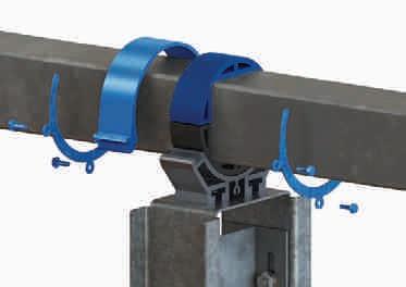
Heavy Saddle Bracket

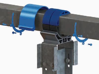

Step F1: Assemble Lateral Plates to Posts Prior to Post Installation
1.0 If required assemble Lateral Stop Plate to post before driving posts using 1/2"x1-1/2" Flange Hex Bolts (x6) and 1/2" Nyloc Flange Hex Nuts (x6). Torque hardware 90-100 ft-lbs.
2.0 As an approved alternative, assemble Lateral Stop Plate to post before driving posts using 1/2"x1-1/2" Hex Bolts (x6), 1/2" Washers (x12), and 1/2" Nyloc Hex Nuts (x6). Torque hardware 90-100 ft-lbs.
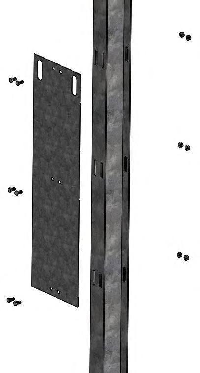
G APPENDIX FOR MOUNTING GLASS/GLASS MODULES
Purlin (GC903TWT)


Module Mounting Hardware:
Double Sided Glass/Glass Module Clips (End)
Glass/Glass Module Clips (End) Double Sided Glass/Glass Module Clips (Mid)
Channel (GC378-.25)
Channel Bottom (GC378BU-.25) Glass/Glass Module Clips (Mid)
• 1/4-20 ¾ inch long buttonhead cap screw (or T bolt or hex bolt) and serrated flange nut –unless otherwise required by module manufacturer
• Glass/Glass Module Clip (End or Mid)

inch U Bolt (GC1301)

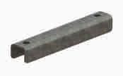


Step G1: Anti-Corrosion Tape Installation (modules in landscape only)
1.0 With Drive Arm Assembly facing west per step 3 install Corrosion Protection Tape on the top portion of the Row Tube (Corrosion Protection Tape is applied to the surface that will be in direct contact with the solar modules).
1.1 Run a rag over surfaces to be coated to remove visible oil, grease, dirt, or other contaminates.
1.2 Ensure the surfaces to be coated are dry prior to install; do not apply tape when raining.
1.3 It is best practice to both use a paint roller, or similar, to aid in the application of the corrosion tape and follow the application of the tape with a nylon roller to remove any air bubbles below the tape as it's being applied.
1.4 Apply one strip of Corrosion Protection Tape on the East or West side 1/2" [0.01 m] to 5/8" [0.02 m] towards grade and the remainder over the top of the Row Tube.
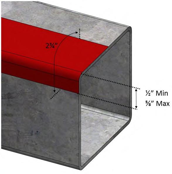

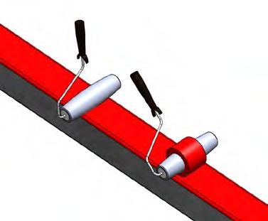
2.0 With Drive Arm Assembly facing west per step 3 install Corrosion Protection Tape on the top portion of the Row Tube (Corrosion Protection Tape is applied to the surface that will be in direct contact with the solar modules).
2.1 Ensure the surfaces to be coated are dry prior to install; do not apply tape when raining.
2.2 It is best practice to both use a paint roller, or similar, to aid in the application of the corrosion tape and follow the application of the tape with a nylon roller to remove any air bubbles below the tape as it's being applied.
2.3 Apply one strip of Corrosion Protection Tape on the East or West side 1/2" [0.01 m] to 5/8" [0.02 m] towards grade and the remainder over the top of the Row Tube.
2.4 Apply a second layer of Corrosion Protection Tape on the opposite side, overlapping the first layer by 1/4" [0.006 m] to 1/2" [0.013 m].
2.5 Run tape along table from one Bearing Collar to the next, continuing to apply over Squeeze Splices.
2.6 Cut the tape at Bearing Collar locations and continue application on other side of Bearing Collar.
2.7 Repeat until top of entire table is covered.
2.8 Repeat for all tables.
Note: Tape can be installed after Tubes and Bearings are placed on posts or after Purlins are installed (tape runs from Purlin to Purlin).
Step G2: Purlin Installation
1.0 Install Purlin onto Row Tube using Purlin Channels (two GC378-.25 on Purlin side and two GC378BU-.25 on Row Tube side), 1/4” U Bolts, and serrated flange nuts. One GC378BUD-.25 may be used in place of the two GC378BU-.25 if provided. Purlins and Purlin Channels shall be centered on the Row Tube prior to torquing hardware. Leave hardware finger tight so Purlins can be adjusted while mounting modules.
2.0 Purlins should be attached at proper locations as noted on Project Construction Drawing provided by GameChange so that they are not located where Squeeze Splices are attached.
3.0 Torque to specification.
4.0 Optionally, Mid Clamps may be preinstalled loosely onto Purlins prior to installation onto the Row Tube, especially if access to the Mid Clamp hardware will be limited once installed.

Step G3: Module Installation
1.0 Make sure to check the install manual for the module you are installing to make sure that the module mounting hardware and installation methodology recommended by GameChange is acceptable. Otherwise you may risk voiding the warranty for your modules.
2.0 See module specification sheet for acceptable locations and tolerances for mounting clips.

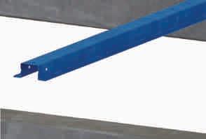


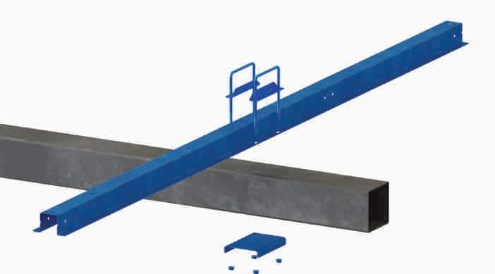
Step G3a: Module Installation for glass/glass non framed modules mounted in landscape
1.0 Attaching outermost module edges along purlin with Glass/ Glass Module End Clips through holes:
1.1 Insert buttonhead cap screw (or T bolt or hex bolt) through Glass/Glass Module End Clip and into the Purlin hole.
1.2 Make sure module frame is tight against the Glass/ Glass Module End Clip.
1.3 Install flange nut on under side of Purlin
1.4 Torque buttonhead cap screw/nut (or T bolt or hex bolt) to specification.
1.5 Make sure bolt head touches down and is flush with module clips. Do not allow bolt heads to ride on module clip shoulder.
2.0 Attaching inner module edges along Purlins using Glass/ Glass Module Mid Clips through holes:
2.1 Insert buttonhead cap screw (or T bolt or hex bolt) through Module Mid Clip and into the Purlin hole.
2.2 Make sure modules are tight up against the Mid Clip on both sides.
2.3 Install flange nut on under side of Purlin
2.4 Tighten buttonhead cap screw/nut (or T bolt or hex bolt)to specification.
2.5 Make sure bolt head touches down and is flush with module clips. Do not allow bolt heads to ride on module clip shoulder.
2.6 For systems with even number of modules on each pair of Purlins (2UP, 4UP, etc), it may help with ease of installation if the center Mid Clip was installed onto the Purlins prior to installing the Purlins onto the Row Tubes. Access will be very limited to thread the flange nut onto the buttonhead screw (or T bolt or hex bolt) once the Purlin is already installed onto the Row Tube.
3.0 The GameChange system provides typical module spacing required, however, it is the customer’s ultimate responsibility to make sure to follow module spacing guidelines if any are given by module vendor in their specification sheet or elsewhere, otherwise module warranty could be voided.
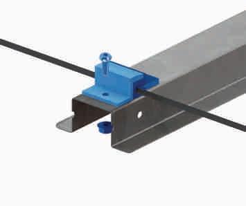
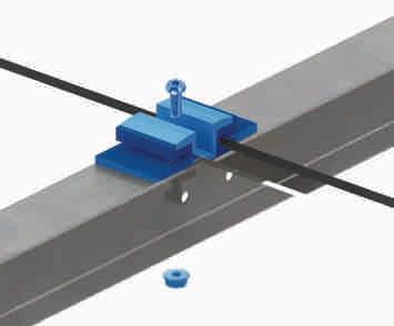
CORRECT: needs to have the bolt head sit on the bottom of the clip and not the shoulder

CORRECT: bird’s-eye view
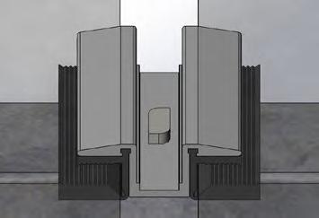
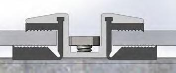
NOT CORRECT: should not look like this and will result in installation issues if done this way. NOT CORRECT: bird’s-eye view
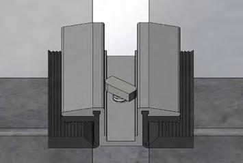
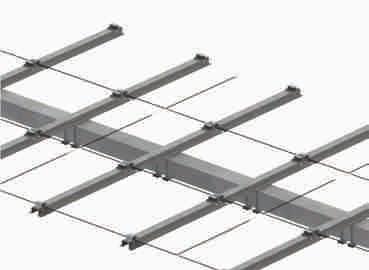
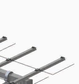
Step G3b: Module Installation for Glass/Glass Non Framed Modules Mounted in Portrait
Top Mount Purlins using Double Sided Glass/Glass Module Clip Mounting (through hole with bolt and serrated flange nut or extruded hole with screw)
1.0 Attaching outermost module edges along purlin with Double Sided Glass/Glass module End Clips through holes:
1.1 Insert hex bolt (or buttonhead cap screw) through Double Sided Glass/Glass Module End Clip and into the Purlin hole, or insert carriage bolt into slot and slide all the way to end of slot and then through Double Sided Glass/Glass Module End Clip.
1.2 Make sure module frame is tight against the Double Sided Glass/Glass Module End Clip.
1.3 Torque bolt/nut to specification.
2.0 Attaching inner module edges along Purlins using Double Sided Glass/Glass Module Mid Clips through holes:
2.1 Insert hex bolt (or buttonhead cap screw) through Double Sided Glass/Glass Module Mid Clip and into the Purlin hole, or insert carriage bolt into slot and slide all the way to end of slot and then through Double Sided Glass/Glass Module Mid Clip.
2.2 Make sure modules are tight up against the Double Sided Glass/Glass Module Mid Clip on both sides.
2.3 Tighten bolt/nut to specification.
3.0 The GameChange system provides typical module spacing required, however, it is the customer’s ultimate responsibility to make sure to follow module spacing guidelines if any are given by module vendor in their specification sheet or elsewhere, otherwise module warranty could be voided.
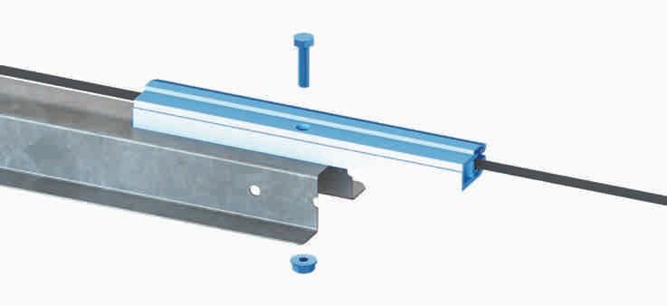
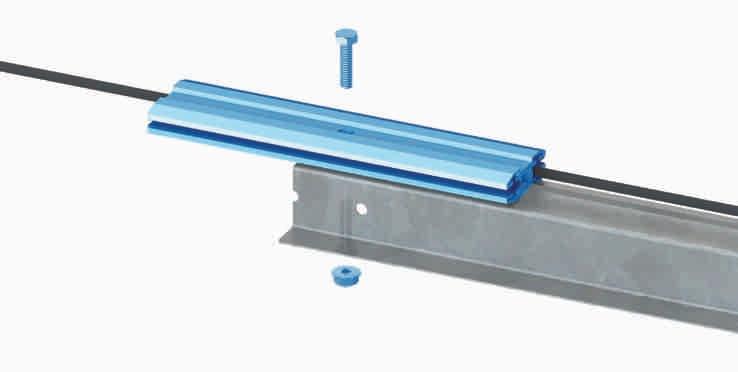
Additional System Components for Seismic Lateral Captures
Purlin Channel Bottom (GC4378BU) U Bolts (GC1325)

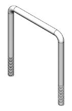
If post requires Seismic Lateral Captures, install on Purlin Channel Bottom. Using a 3/8" square U-Bolt, capture the Purlin Channel Bottom around the Row Tube and finger tighten on 3/8" nut. Position the Purlin Channel Bottom such that the edge is 1/8" away from the Bearing Assembly. Torque to spec.

I APPENDIX FOR LINKAGE SYSTEM INSTALL INSTRUCTIONS
The linkage system connects two rows of solar panels, allowing a single actuator mounted on the primary row to move both rows together.
The Linked Row implementation of the Genius Tracker has a significant capacity to function on sloping ground. However, the Linked Row Genius Tracker shall not be installed on ground with a North-South slope exceeding 7%, or an East-West slope exceeding 10%.
1.0 At the location shown on the Table Details, next to the Center post of the primary table, attach Linkage Arm Assembly to Row Tube using 1/2-13 x 6" Long hex bolts and flange nuts. Place the Linkage Arm in the open gap to the North of the Actuator. See Table Details in construction drawing for exact location of gap. Torque 1/2” hardware to specification.
2.0 The distance measured from the edge of the Center Post flange (or the edge of the Saddle Bracket, whichever is wider) to the edge of the Linkage Arm Ridgeback shall be at least 7” (17.8 cm). Ensure that the Linkage Arm is as close to the Center Post as possible without interfering with the Charging Module or other components.
3.0 Install two 3/8” TEK screws in the Linkage Arm (one on either side of the Row Tube). Be sure to place them on the side closest to the Actuator on the Primary table and the Center Post on the Secondary table .

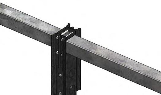

4.0 Repeat the process to install linkage arm on the secondary table. Make sure identical measurements are made from the Linkage Arm Ridgeback to the Center Post flange (or the edge of the Saddle Bracket, whichever is wider) to ensure that the Linkage Arms on the Primary and Secondary tables are aligned.
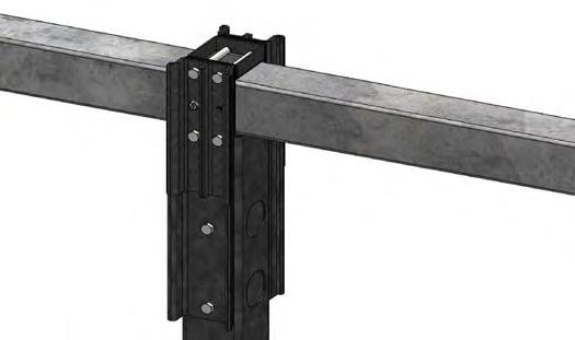
I Do not mount wires on linkage tube or use linkage tube to support wire management systems.
5.0 On the secondary table only, install four Purlin Channel Bottoms (GC378BU), two Square U bolts (GC1325), and four 3/8” nuts to the North and South of the Center Bearing Collar as shown below. Position the GC378BU such that the edge is 1/8” (3 mm) away from the edge of the Bearing Collar. Torque to spec. After Purlin Channels are installed, install two 1/4” TEK screw (one per side) such that the TEK screw is right up against the edge of the Purlin Channel.
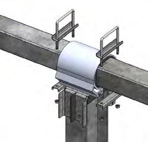
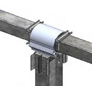

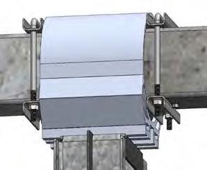
6.0 Ensure that the Linkage Arms on both the primary and secondary tables are plumb (0±0.4°). On the primary table, align the first hole (the hole closest to the end of the Linkage Tube) with the pin of the Linkage Arm.

FIRST HOLE
7.0 On the secondary table, check the alignment between the Linkage Arm pin and the nearest hole on the Linkage Tube. If the difference between the two is greater than 1/4 inch [6mm], shift the Linkage Tube towards the primary table until the secondary Linkage Arm is aligned vertically with the next hole. Check the alignment between the primary Linkage Arm and the nearest hole of the Linkage Tube. If the difference between the two is greater than 1/4 inch [6mm], shift the Linkage Tube towards the primary table until the primary Linkage Arm is aligned vertically with the next hole. Repeat this process, alternating sides until a set of holes results in an alignment of 1/4 inch [6mm] or less.

8.0 Attach both Linkage Arms to the Linkage Tube using the punch pattern alignment from step 11.7, using a 1” (2.54 cm) diameter clevis pin. The clevis pin shall pass through one pivot plate, a washer, the Linkage Tube, a second washer, and the second pivot plate. Then, insert the 4.5mm linch pin through the clevis pin and rotate the hoop in the linch pin to complete the assembly.
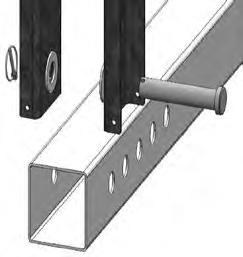
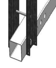
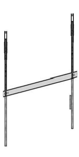
J APPENDIX FOR TERRAIN FOLLOWING
Step J1: Row Tube Preparation
NOTE: Pile Drivers with GPS must be used for post install for TF system.
1.0 Center Bearing Collar Preparation: Place six 1/2-13 carriage bolts into Bearing Collar. Place bearing collar with carriage bolts over Saddle Bracket and lower such that bolts slide through slots in top of saddle bracket. Install one ½ nut on one 1/213 carriage bolt and torque to finger tight only.
2.0 Typical Bearing Collar Preparation: Place two 1/2-13 carriage bolts into Bearing Collar. Place bearing collar with carriage bolts over Saddle Bracket and lower such that bolts slide through slots in top of saddle bracket. Install one ½ nut on one 1/2-13 carriage bolt and torque to finger tight only.
3.0 Heavy Bearing Collar Preparation: Place four 1/2-13 carriage bolts into Bearing Collar. Place bearing collar with carriage bolts over Heavy Saddle Bracket and lower such that bolts slide through slots in top of saddle bracket. Install one ½ nut on one 1/2-13 carriage bolt and torque to finger tight only.
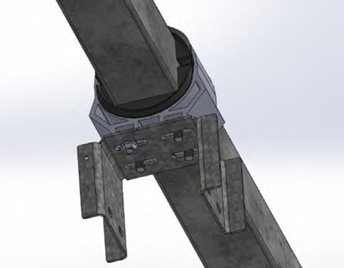
4.0 Center Row Tube Preparation: Slide Center Bearing Collar and Saddle Bracket assemblies onto Row Tube. If using preassembled SpeedClamps™ or preassembled Purlins, place the appropriate number of SpeedClamps™ or Purlins along the Row Tube between Bearing and Saddle Bracket Assemblies.
5.0 Typical Row Tube Preparation: Slide Typical and/or Heavy Bearing Collar and Saddle Bracket assemblies onto row tube. If using preassembled SpeedClamps™ or preassembled Purlins, place the appropriate number of SpeedClamps™ or Purlins along the Row Tube between Bearing and Saddle Bracket Assemblies.
6.0 Tubes may vary in length due to manufacturing tolerances. Typically, tolerances within 1/8” [3 mm] will not affect installation. If lengths vary outside of typical tolerance, please consult with GameChange on options to keep table lengths consistent with Project Construction Drawings
Step J2: Center Row Tube Installation
1.0 Locate Center Row Tube above Center Post. Row tube shall extend north and south of Center Post for distances shown in Project Construction Drawings.
2.0 Orient Center Row Tube with North-South slope to align with top of center post and top of adjacent post supporting the tube.
3.0 Attach Wide Flange Center Saddle Bracket onto the top of the Wide Flange Center Post using eight 1/2-13 flange hex bolts and serrated flange nuts. Tabs on Center Saddle Bracket must be on East side. Align Wide Flange Center Saddle Bracket with North-South slope of Row Tube.
4.0 If Center Post is out of plumb in the E-W direction, Drive Housing shall be installed uphill on the Saddle Bracket opposite the direction the out-of-plumb Center Post is pointing. Doing this is important to maintain system operation within the designed tilt ranges. Torque hardware to specification. Open end crowfoot wrench may be required to extend torque wrench.
5.0 Rotate Bearing Collar around vertical so that saddle bracket is aligned with post flanges and bearing collar is aligned with row tube (project azimuth). Install ½” nuts on remaining five 1/2-13 carriage bolts
6.0 On adjacent post, attach Saddle Bracket to top of post using four 1/2-13 flange hex bolts and serrated flange nuts. Rotate Bearing Collar around vertical so that saddle bracket is aligned with post flanges and bearing collar is aligned with row tube (project azimuth). Install ½” nuts on remaining 1/2-13 carriage bolts.
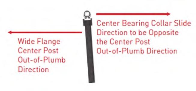
Step J3: Squeeze Splice Installation
1.0 Align Typical Row Tube next to Center Row Tube. Join one Row Tube to the next using Squeeze Splice. Install two squeeze splices at each tube to tube connection within a table, using eight 1/2” bolts and flange nuts per connection. Install the 1/2” hex bolt (not flange) with the thread pointing away from the panel. Once all Row Tubes for a single table are joined, tighten all hardware to specification.
2.0 Make sure there is 1/4” [6 mm] between the tubes.
3.0 If one end of the tube is notched, make sure the tab on at least one side of the tube is not notched.
4.0 Squeeze Splice shall be hand tightened first, then tightened in a star pattern, alternating sides. Then apply final torque in a star pattern, alternating sides. Refer to numbers for order of torquing.
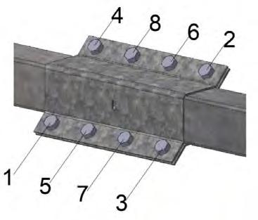
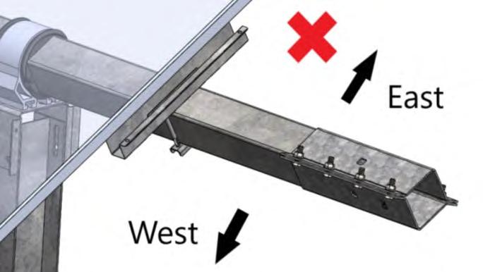
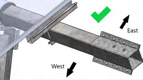
Step J4: Typical Row Tube Installation
1.0 Align Typical and/or Heavy Saddle Bracket and Bearing Collar Assembly at top of post. Attach Saddle Bracket to top of post using four 1/2-13 flange hex bolts and serrated flange nuts, do not fully tighten.
2.0 Rotate Bearing Collar around vertical so that saddle bracket is aligned with post flanges and bearing collar is aligned with row tube (project azimuth). Install ½” nuts on remaining 1/2-13 carriage bolts
3.0 Rotate Saddle bracket about East-West axis until North-South Slope of saddle bracket aligns with slope of row tube at post location within 1 degree.

4.0 Measure North-South Slope of top of saddle bracket and compare to North-South Slope of top of adjacent saddle bracket. Confirm they are within maximum slope change stated in project construction drawings. If not, use vertical adjustability of saddle bracket to post connection to bring row tube slope and slope of saddle bracket slopes into tolerance.
5.0 Torque ½ bolts to specification.
6.0 Repeat for adjacent Typical Row Tube segments.
K APPENDIX FOR ALTERNATE ACTUATOR BONDING
Option 1:

1.0 Position 3/8” [9mm] above the motor casing and drill 0.22” diameter hole into this face of eyelet at a depth of ¾” [19 mm] max. Install braided jumper using ¼-14x3/4” length TEK screw into 0.22” pre-drilled hole.
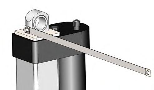
Option 2:
1.0 Using existing bolts, install 2 stainless steel washers as shown below. Make sure the washers are place entirely inside the housing such that the braided jumper will touch the metal surface
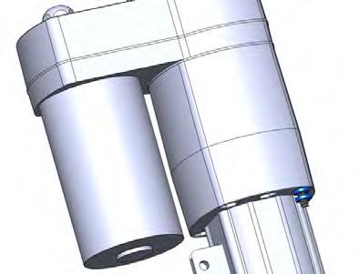
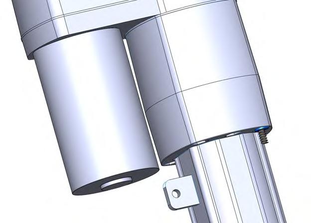
2.0 Install braided jumper. Make sure the braided jumper is touching the steel of the actuator for proper bonding.
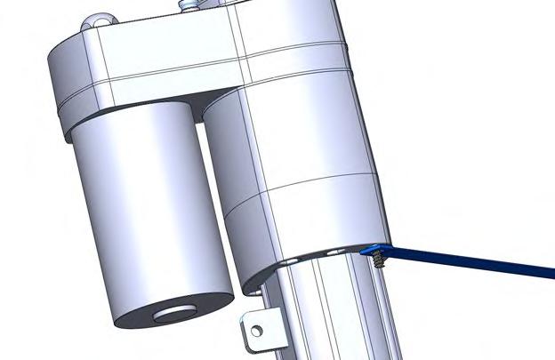
3.0 Install lock nut to fasten the braided jumper.

L APPENDIX FOR RECTANGULAR HEAD BOLTS
Components
• GC1391 Rectangular Head Bolt
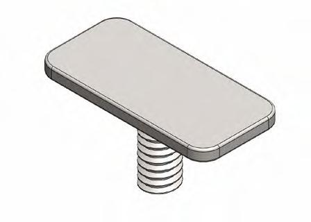
Installation
1.0 Install purlins in accordance with Steps 10 and 13 of the Genius Tracker install manual.
2.0 Install PV modules onto Purlins using rectangular head bolts and ¼” serrated flange nuts. One of the bolts used to mount each PV module must be the Rectangular Head Star Bolt to bond the module to the system.
3.0 Attach with a rectangular head bolt inside the module and serrated flange nut outside the Purlin. Torque ¼” nut to specification. Head of rectangular head bolt should catch on inside face of vertical wall of panel frame.
• GC1392 Rectangular Head Star Bolt
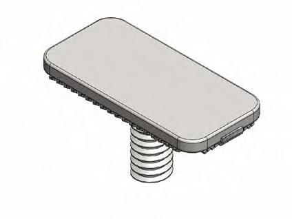

GC1391 Rectangular Head Bolt Installation
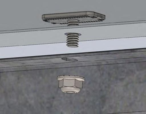
GC1392 Rectangular Head Star Bolt Installation
M APPENDIX FOR GC2008-H AND GC2508 ACTUATORS
GC2008-H Linear Actuator
The GC2008-H Linear Actuator is based on the design of our standard Linear Actuator, but has been upgraded and reinforced throughout to provide an increase of 33% in overall strength and durability.
It operates at a temperature range between -40° C and +65° C.
GC2508 Linear Actuator
The GC2508 Linear Actuator is based on the design of our standard Linear Actuator, but has been upgraded and reinforced throughout to provide an increase of 33% in overall strength and durability.
It operates at a temperature range between -40° C and +65° C.
INSTALLATION
The GC2008-H and GC2508 shall be installed using the same process as shown in Step 8 above.
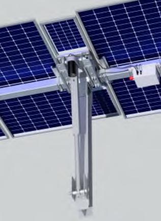
N APPENDIX FOR GEN4 NODE CONTROLLERS
Introduction
The Gen4 Node controller is an update to the previous Node Controller, featuring a number of new features:
• New LCD display and front-mounted control panel for inspection and direct control of the node
• New LFP battery
• New node enclosure with access panel for battery replacement
• No external fuse
Gen4 Node Controller Installation
There are separate instructions for installing the Gen4 Node Controller on the GC4600FH drive arm, or the GC4600 FEH drive arm.
I Prior to installing controllers, ensure E-Stops are pressed in and Actuator Power Connector cover is firmly in place.
I Do not carry node controller by the cables meant for connection of the controller to the Small Charging Module or actuator. Doing so will damage the connection. If cables are zip-tied or taped, do not remove until installing onto Row Tube and to the Small Charging Module.
I Ensure proper space in provided around the Node Controller so that the emergency stop is easily accessible.
I Installer will notify GameChange Solar 90 days before node controllers are ready to be installed and plugged into Small Charging Module. GameChange will then deliver node controllers which must be installed, fused, and plugged into Small Charging Module within 2 weeks of delivery to site, or irreparable damage to battery may occur and void warranty on battery. All costs for battery replacement will be borne by customer/ installer.
I For Projects Located in Canada
For Projects Located in Canada, the controller installation, including wiring methods, shall be in accordance with the Canadian Electrical Code or CSA C22.1.
Charging Panel Installation
The Gen4 Node Controller uses the standard Genius Tracker Charging Panel installation.
See “Charging Panel Installation” in the Installation of System chapter of this manual.
Gen4 Node Controller Installation
1.0 The Gen4 Node Controller shall be attached to the Row Tube South of the Charging Panel. It shall be centered under the first PV module to the South of the Charging Panel, with the Front Panel of the Node Controller facing North, and the Emergency Stop facing Northwest.
2.0 Attach the Gen4 Node Controller to the Row Tube using 3/8” U bolts, nuts, and Purlin Channels.
I Be sure to tighten the U bolts and nuts until the Node Controller enclosure is flush against the Row Tube on both sides of the enclosure. Failure to do so can degrade the accuracy of the inclinometer readings.
I Do not carry Node Controller by the cables meant for connection of the controller to the charging module. Doing so will damage the connection to the charging module. If cables are zip-tied or taped, do not remove until installing onto Row Tube and to the Charging Module.
I Be sure all nuts are finger-tight then torqued to 10 ft-lbs [13.5 N-m].
I Distance between Center Post and Controller should be a minimum of 18 inches [0.457m].


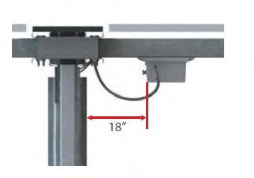

Any malfunctioning node controller shall be uninstalled and replaced with a new, GameChange Solar-supplied node controller. All conductors and cables associated with the node controller, actuator, sensors, and charge module shall be managed so that a bend radius equal to or greater than 5 times the radius of the cable is maintained throughout articulation of the tracker. Failure to adhere to this requirement will void the warranty associated with damage incurred where not installed properly.
3.0 Plug actuator cable into connector on the underside of the Node Controller. When properly connected, an audible click is heard when plugging the Actuator Connector into the Node Controller. Ensure that Actuator connector is securely connected to Node Controller.
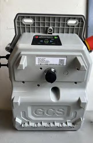
4.0 Plug Charging Panel wires into mating wires on Node Controller. When properly connected, an audible click is heard when plugging the Charging Panel wires into the Node Controller. Ensure that Charging Panel wires are securely connected to Controller.
I Install Node Controller and connect Charging Module to Node Controller no later than 2 weeks after the batteries are delivered. Delay in connecting Node Controllers to Charging Module may cause irreparable damage to battery in Node Controller.
5.0 Scan Node Controller Barcode using the GCS Web App.
6.0 Release E-Stop on Node Controller. This may require either a twist or pull motion.
7.0 If the Node Controller is not turned on, press the power button on the front control panel for three seconds to power on the Node Controller.
8.0 Press the INFO button on the front control panel, then use the up and down buttons to switch between the readouts on the front panel and verify that the node has powered on and is communicating.


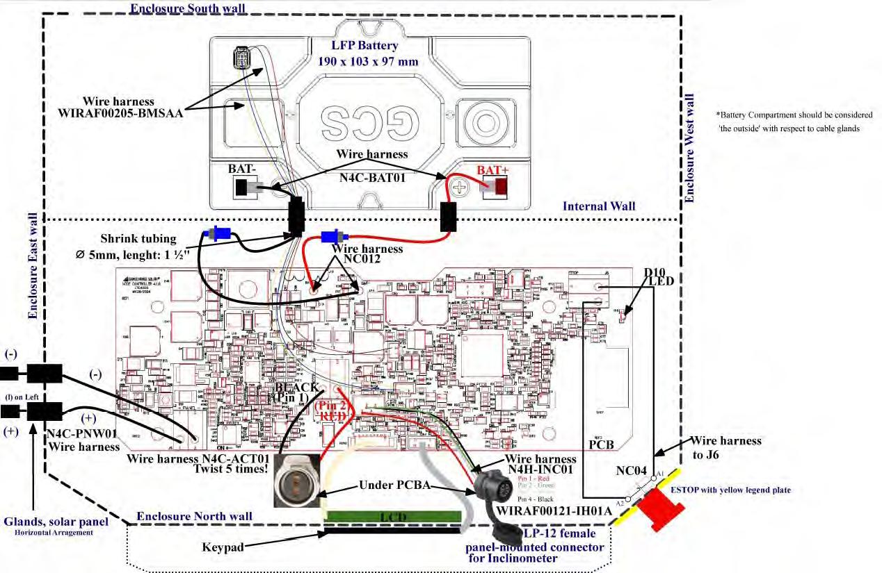
This procedure may be used to rotate arrays prior to inverter energization and commissioning. Automating the process to rotate arrays earlier during installation may reduce labor costs and improve system safety during construction. This document describes the procedure for Install Teams to perform stow operations for the Node Controllers associated with a single Master Controller.
Prerequisite Operations
This procedure is to be carried out after the following stage in the install process:
• The posts, bearings, and row tubes have been installed
• The Charging Panel, Actuator and Node Controller have been installed, fused and connected.
• The Master Controller has been installed, but not necessarily connected to AC power.
• Node Controllers are scanned in.
• Master Controllers have been remote commissioned and provisioned in the GCS Web App.
NOTE: This process can only be performed for one Master Controller at a time. Attempting to setup more than one Master Controller at a time will cause problems with the LwMesh mesh network and prevent the procedure from being successful.
I After the procedure is complete, the Node Controllers must be returned to the Safety Stow position before the end of the day to prevent damage to the components.
NOTE: After Master Controllers have been installed and nodes are scanned in, please reach out to GCS Commissioning for remote commissioning support.
Equipment Required
The following equipment is required:
• Electrical generator or other power supply of at least 1000W capacity
• 50 foot Heavy-Duty 3 Prong Extension Cord rated for outdoor
•
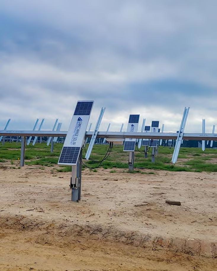
GCS Remote Commissioning Process Overview
The overall process is as follows:
1.0 Using the Web App, scan the Node IDs for all of the Node Controllers assigned to the Master Controller.
2.0 Please provide the modem IP Address associated with the Master Controller to be provisioned.
3.0 Contact GCS Commissioning for Remote Commissioning support or support@gamechangesolar.zendesk.com
4.0 Attach the Master Controller to the electrical generator and power it on.
5.0 Use the Web app to perform the following steps:
5.1 Use the Reset Stow Coordinator command to clear any stow conditions.
5.2 Clear Alarms and Flags
5.3 Use the Tracking Enable command to enable Algorithmic Solar Tracking.
5.4 Use the Manual Stow - Custom Angle command to stow all nodes. This will allow the Install Team to stow the tables flat for installing PV modules and wiring, or move them east or west to mow around them or move large equipment.
5.5 Return all nodes to the Safety Stow position before the end of the day.
6.0 Power down the Master Controller and disconnect the generator.
See the following pages for detailed steps.
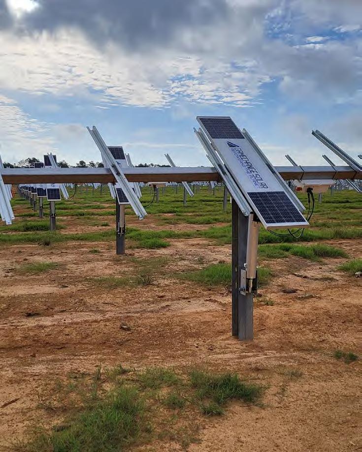
Scanning Node IDs with the GCS Web App
Scanning and assigning node IDs via the GCS Web Application assigns nodes to a specified zone and location allowing the Master Controller to communicate with the nodes.
Tips:
• Starting at the master will help orient yourself with the site layout, it is imperative that nodes are scanned in according to the site layout!
• If data connection is lost while scanning in node ID’s, the node ID’s will be saved to the app and uploaded when data or wifi is re-established.
• It is advised to have a spare power bank for phone, although not necessary.
To scan Node IDs with the GCS Web Application:
1.0 Log into the GCS Web App using the credentials provided by GCS. After logging in, the Layouts screen will display.
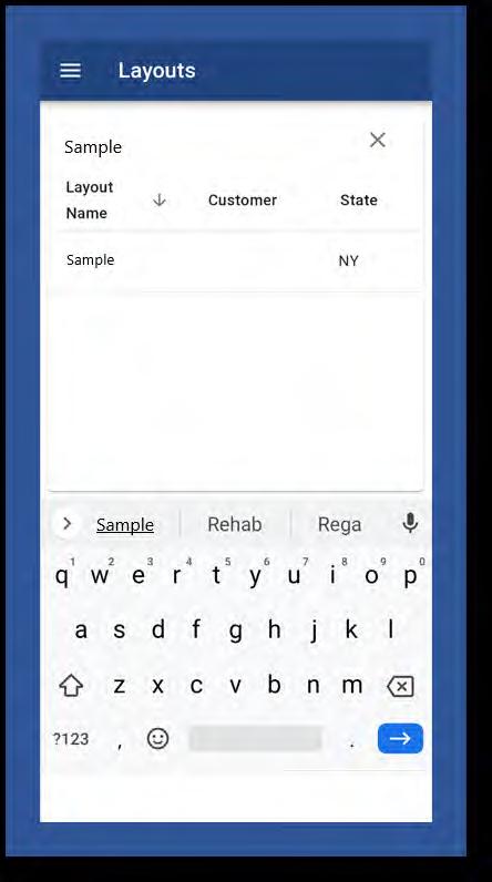
2.0 Find your Genius Tracker site in the list and click on it, or use the search field to search for your site and click on it. The site will appear in the Site View screen.
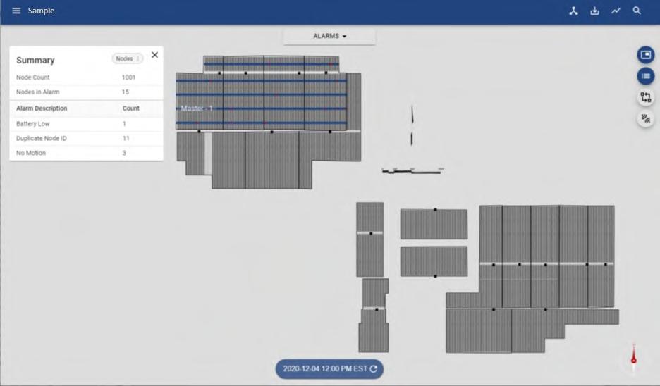
3.0 From the drop-down menu at the top center of the screen, select Device ID Assignment.
4.0 Select the Master Controller to which you want to assign the node IDs.
5.0 Once you have selected the master, the zone will appear to have rows of grey dots. These dots represent unassigned nodes. Each node represents one table.
6.0 Click on the node you would like to begin scanning in. A white dialogue box will appear above the node.
7.0 Select the Node ID: Not Assigned dialogue box. You are now ready to scan the node ID with your device. You may scan node ID with device camera or manually typing in the last 4 digits of the radio ID.
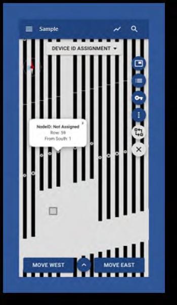
8.0 Selecting the ‘Scan option’ icon indicated by the blue arrow will allow for the node ID to be scanned with your device.
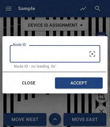

9.0 The device camera will open allowing you to scan the Node ID from the barcode on the label of the Node Controller.
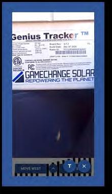
SCANNING THE NODE ID FROM THE BARCODE ON THE NODE CONTROLLER
10.0 You may also input the Node ID manually by selecting the ‘Blue Circle’ with the white T and input the last 4 of the radio ID.
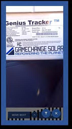


Use last 4 of node ID when manually entering the Node ID, as shown here.

Selecting this will allow for manual input.
11.0 A successfully scanned node will appear as below in the example. Using the ‘East’ or ‘West’ buttons will allow continue scanning nodes with ease. Selecting the ‘Key Icon’ provides more information on node dot color.
12.0 Repeat as necessary until all nodes are scanned in.
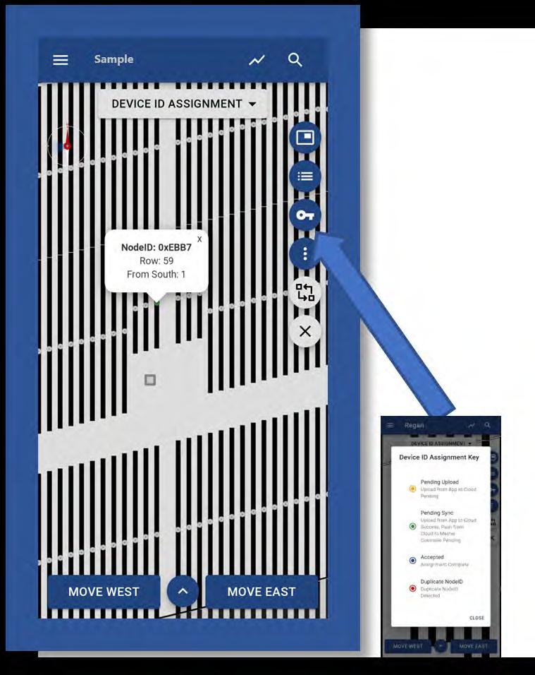
SUCCESSFULLY SCANNED NODE
Powering Up the Master Controller
Starting the Generator/Power Source
The general plan is to run the Master Controller off of a temporary power source such as a gas powered portable generator like a Honda EU2200.
Other possible power sources include:
• Other gas or propane inverter generators, minimum 2200W.
• A battery type generator, minimum 1000W/1000Wh
• Deep cycle DC batteries hooked up to an inverter yielding a minimum of 1000W
• A pickup truck with built-in power generation like the Ford F-150 Pro Power Onboard system.
• Standard 110-220V AC three prong electrical outlets, if available.
The power source should be turned on and running before connecting the Master Controller, so as to avoid any power spikes/ drops at startup, and to give it time to stabilize.
Connecting the Master Controller to the Power Source
The GCS Master Controller is supplied with a pigtail cable with a 3-prong American Standard NEMA 5/15P plug.
This should be connected to a heavy duty three prong extension cord rated for outdoor use, such as the standard 50 foot orange extension cord.
I Do not connect the power supply when the plugs and/or sockets are wet.
Plug the extension cord into the power source. Ensure the connection is made weatherproof.
Powering On the Master Controller
The Master Controller will power on as soon as it is connected to a power source.
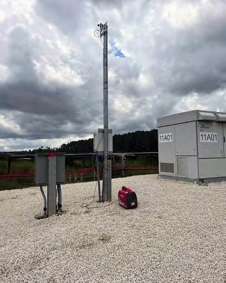
Operating the Master Controller Using the Web App
Connect to the GCS
Web Application
The GCS Web Application connects to the Master Controller using the wireless modem installed in the Master Controller enclosure.
To connect to the Master Controller using the GCS Web Application:
1.0 Log into the GCS Web App using the credentials provided by GCS. After logging in, the Layouts screen will display.
2.0 Find your Genius Tracker site in the list and click on it, or use the search field to search for your site and click on it. The site will appear in the Site View screen.
3.0 To select the Master Controller:
3.1 Click on the Master Select icon, at the top of the column of icons along the upper right side of the screen. THE MASTER SELECT ICON
3.2 A pop-up window with a list of the Master Controllers at the selected site appears.
3.3 Click on the checkbox for the Master Controller you want to work with. Make sure all of the other Master Controller checkboxes are cleared.
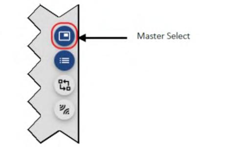

3.4 Click on the word balloon icon to the right of the Master Controller listing to open the Master/Node screen for that Master Controller.
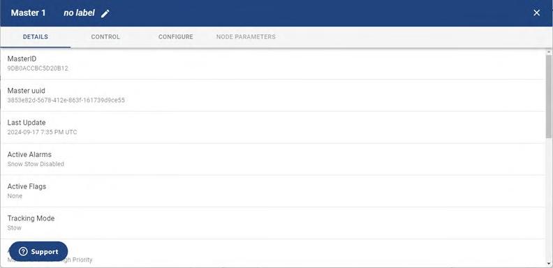
3.5 Click the CONTROL link in the toolbar running across the top of the screen to access the CONTROL tab of the Master/Node screen. You are now ready to send commands to the Master Controller.
Run the Reset Stow Coordinator Command
Run the Reset Stow Coordinator command to clear any stow conditions that may be in place.
To run the Reset Stow Controller command:
1.0 Access the CONTROL tab of the Master/Node screen.
2.0 Select the Master Controller from the Select Master list.
3.0 Select Reset Stow Coordinator from the Select Command list.
4.0 Click the Run Command button at the bottom of the list.
5.0 Check the output from the command that appears underneath the RUN COMMAND button, if any, to determine if the command ran successfully.
Clear Alarms and Flags
Use the Reset All Node Alarms and Reset Flags commands to clear all alarms and flags to allow algorithmic solar tracking.
To clear all alarms and flags:
1.0 Access the CONTROL tab of the Master/Node screen.
2.0 Select the Master Controller from the Select Master list.
3.0 Select Reset All Node Alarms from the Select Command list.
4.0 Click the Run Command button at the bottom of the list.
5.0 Once the command finishes running, select Reset Flags from the Select Command list.
6.0 In the Select Flags to Reset list that appears below the Select Command list, select Select All.
7.0 Click the Run Command button.



Use the Tracking Enable Command
The Tracking Enable command enables algorithmic solar tracking. To enable algorithmic solar tracking:
1.0 Access the CONTROL tab of the Master/Node screen.
2.0 Select the Master Controller from the Select Master list.
3.0 Select Tracking Enable from the Select Command list.
4.0 Click the Run Command button at the bottom of the list.
Check the output from the command that appears underneath the RUN COMMAND button, if any, to determine if the command ran successfully.

TAB OF MASTER/NODE SCREEN

Use the Manual Stow-Custom Angle Command
Use the Manual Stow - Custom Angle command to stow all nodes. This will allow the Install Team to stow the tables flat for installing PV modules and wiring, or move them out of the way to mow around them or move large equipment.
To stow the nodes:
1.0 Access the CONTROL tab of the Master/Node screen.
2.0 Select the Master Controller from the Select Master list.
3.0 Select Manual Stow - Custom Angle from the Select Command list.
4.0 Enter the desired stow angle in the Enter Angle field that appears underneath the Select Command list.
5.0 Click the Run Command button at the bottom of the list.
6.0 Check the output from the command that appears underneath the RUN COMMAND button, if any, to determine if the command ran successfully.
NOTE: Tables shall be left in stow when not being actively worked on prior to commissioning. For ease of panelization or wire installation, table may be temporarily rotated up to 25 degrees East position while wind speed is under 22 mph [10 m/s]. Table shall be rotated back to stow when not actively being installed.

TAB OF MASTER/NODE SCREEN


Return All Nodes to the Safety Stow Position
At the end of each work session, use the Safety Stow – Strongest Angle command to move the nodes into the safety stow position, overriding all other statuses.
NOTE: After the procedure is complete, the Node Controllers must be returned to the Safety Stow position before the end of the day to prevent damage to the components.
To move the nodes to the Safety Stow position:
1.0 Access the CONTROL tab of the Master/Node screen.
2.0 Select the Master Controller from the Select Master list.
3.0 Select Safety Stow – Strongest Angle from the Select Command list.
4.0 Click the Run Command button at the bottom of the list.
5.0 Visually confirm that all nodes have moved to the 450 West Safety Stow position.
CONTROL TAB OF MASTER/NODE SCREEN

Powering Down the Master Controller
Once the nodes have been returned to the safety stow position, you can simply unplug the Master Controller from the generator or other power supply.
P APPENDIX FOR INSTALLING PURLINS IN LEGS-UP U-BOLT
1.0 Ensure assembled Center Bearing Collars have 6 Bearing Wheels included. Ensure each assembled Standard Bearing Collar has two Bearing Wheel, Single Piece inserts in them. Ensure each assembled Standard Bearing Collar Heavy has two Bearing Wheel, Single Piece inserts in them. Refer to Post Schedule for selecting Bearing Collar Widths for each Post.

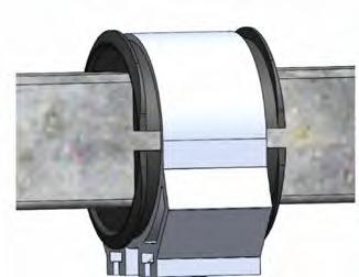
2.0 Pre-stage assembled Center Bearing Collars onto the Row Tube to be installed onto the Center Post, along with appropriate number of assembled Purlins and assembled Standard Bearing Collars.
3.0 Purlins may not come pre-assembled. If they are not preassembled, assemble them by placing the Purlin inside the Reinforcement Channel and the Purlin Channel inside the Purlin. On Perimeter Purlins only (typically colored Red) insert a Purlin Channel Bottom inside the Purlin Channel. Make sure all of the holes line up. If provided with a longer Reinforcement and Purlin Channel that needs to be fastened through the Purlin, fasten the Channels together using 1/4” Flange Bolt and Nut in the holes provided in the Purlin and Channels and torque the 1/4” hardware to spec. Insert the U-bolt with the threads facing up (i.e. away from the ground) and install the 3/8” Nyloc nuts, leaving them loose until Purl ins are in the correct positions. It is recommended to use a Trigger Clamp, or equivalent, to squeeze U-bolt legs for easier install and alignment. CENTER
4.0 Take assembled Purlins and pre-position along the Row Tube by loosening the flange nuts enough that the space between the Reinforcement Channel and the U-bolt is larger than the Row Tube, and sliding the appropriate number of assemblies onto the Row Tube at the approximate locations they will be needed. Once Purlins are set, torque to spec. Be sure to quality check the torque of the U-bolts prior to placing panels on the Purl ins.
• If 6” Long U-bolts are received, extra deep sockets will be required to torque nuts.
• Legs of U-bolt may need to be aligned with bolt holes in Purlins manually.
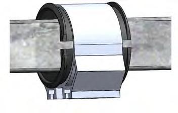
STANDARD POST, STANDARD BEARING COLLAR, HEAVY
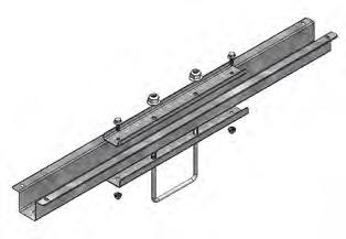
STANDARD POST, STANDARD BEARING COLLAR
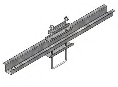


5.0 Slide the Bearing Collars along the Row Tube 6” [152mm] to the North or South side of Saddle Bracket. Rotate Bearing Collars 90° so that the bottom slots face the installer. Pre-stage 1/2-13 carriage bolts into Bearing Collar slots such that spacing of bolts matches slot spacing on Saddle Bracket (6 per Center Saddle Bracket, 4 per Heavy Saddle Bracket, and 2 per Standard Saddle Bracket). Rotate Bearing Collar back so bolts are facing down towards the ground. With hand on top of Bearing Collar, slide back over Saddle Bracket. Lower Row Tube, guiding Bearing Collar with hand on top so that bolts fit into Saddle Bracket Slots. If bolt alignment adjustment is needed, use wrench or similar tool to tap bolts into alignment.
Center Bearing Collars shall be centered on Saddle Bracket to within +/- �� inch [12mm] North-South All Bearing Collars shall be aligned to within +/- 1 ° of the Row Tube (North-South table slope). Torque hardware to spec. Use crowfoot wrench if necessary, and reduce torque as per instructions on page 28 if crowfoot is used.
If provided, use bearing fork tool to keep bolts aligned with slots in Saddle Bracket.
I Never place hand or body part between Bearing Collar and Saddle Bracket.
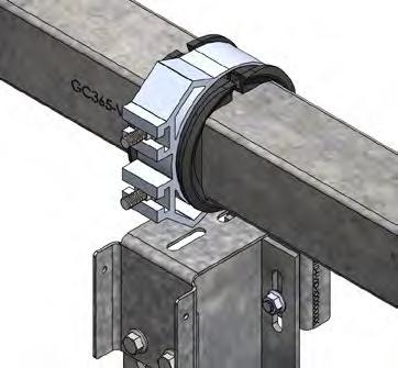
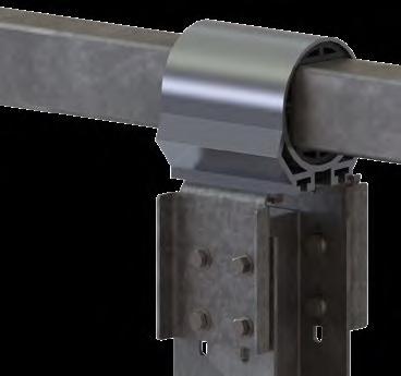
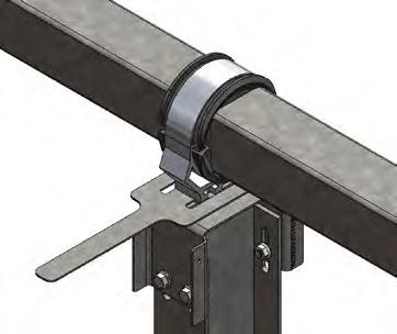
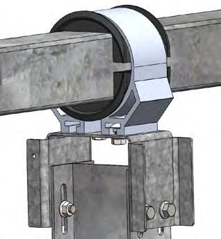
6.0 See “Torque Requirement Modification with Torque Wrench Extender” on page 28 for tips and torque requirements if using an open end crowfoot to torque 2-slot in-line typical saddle brackets.
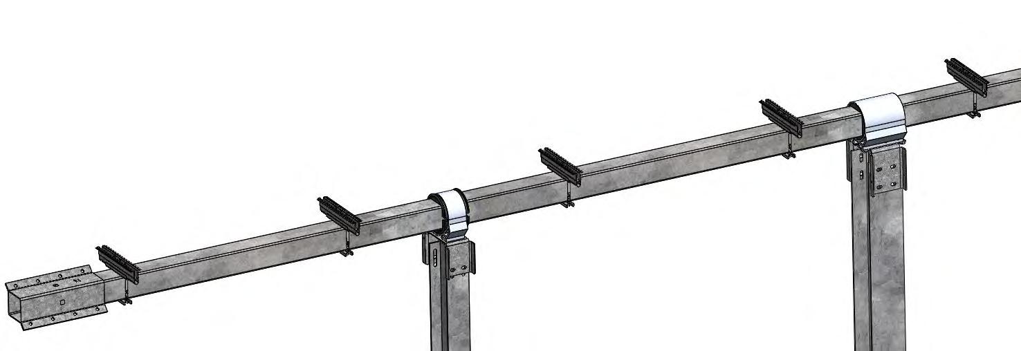
Q APPENDIX FOR POST COUPLERS
Preassemble Couplers to Z Posts
Assemble Post Couplers onto the Z Posts.
Using pre-assembled M10x30mm long hardware, separate the Bolt and Nut and attach the Couplers to the Posts as shown below.
! It is best practice to have the bolt head inside the Post and Coupler and the nut outside the Post.
After hardware is installed, torque to specification.
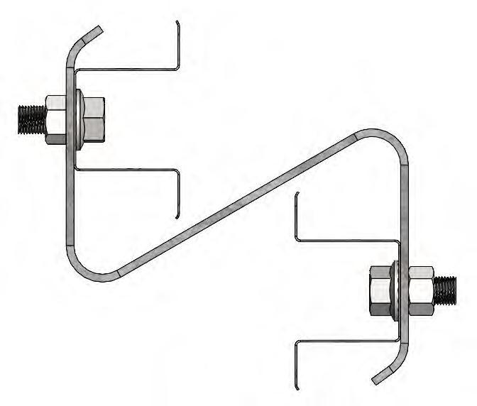
Pre-assemble Couplers to I-Beam Posts
Assemble Post Couplers onto I-Beam Posts.
Using pre-assembled M6x30mm long hardware, separate the Bolt and Nut and attach the Couplers to the Posts as shown below.
! It is best practice to have the bolt head inside the Post and Coupler and the nut outside the Post.
After hardware is installed, torque to specification.
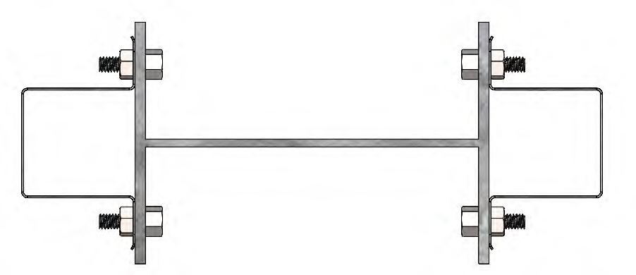

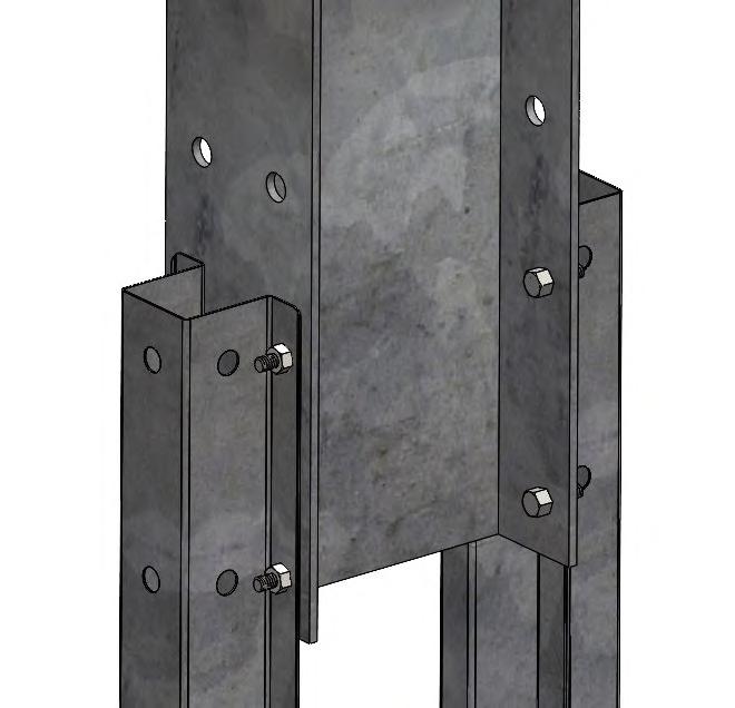

GENIUS TRACKER


GameChange Solar i s driven b y its mission to repower t he p lanet with c lean s olar energy. We do o ur part by driving fixed tilt racking and tracker equipment costs lower. With over 29 GW sold, GameChange systems combine fast i nstall, bankable q uality and unbeatable v alue t hrough s uperior engineering, innovative design and high volume manufacturing.


HEADQUARTERS
230 East Ave
Suite 100
Norwalk, CT, USA
Phone: +1 (203) 769-3900
Fax: +1 (646) 607-2223
gamechangesolar.com
media gamechangesolar.com
GLOBAL LOCATIONS
El Paso, TX
Florence, SC
Dublin, Ireland
Madrid, Spain
Suzhou, China
Bangalore, India
Dubai, UAE
Buenos Aires, Argentina
Johannesburg, South Africa
Newcastle, Australia
RESEARCH & DEVELOPMENT CENTER
Brimfield, MA, USA
SERVICE SUPERCENTERS
Lakeland, FL, USA
Mesa, AZ, USA
Santiago, Chile
Madrid, Spain
Bogotá, Colombia
Ahmedabad, India


I INTRODUCTORY NOTES
This document is GameChange Solar Confidential Information subject to the Confidentiality Agreement between GameChange Solar and the recipient of this document. This document is intended for GameChange Solar Genius Tracker™ customers only. Reproduction or re-distribution without the written consent of GameChange Solar is strictly prohibited. GameChange Solar reserves the right to update this document at any time without written notice.
In order to maintain system warranty:
• All maintenance and repair must be performed by a GameChange solar qualified technician or project O&M personnel who have been trained by GameChange.
• GameChange Solar must be provided real time or near real time access to Genius Tracker™ data as collected by the Master Controller.
I Note: Any modification to the Genius Tracker™ system without prior written approval by GameChange engineering will void warranty.
I Note: For O&M Operations, table may be temporarily rotated to flat while wind speed is under 20 mph only. Table shall be rotated back to stow or put into normal operation when O&M is not actively being performed in area of table or if wind speed exceeds 20 mph.
Always work safely; ensure proper PPE and safety precautions are taken prior to and during maintenance or repair of the system. Only qualified personnel should operate, maintain, or repair the system. GameChange Solar is not responsible for any injury to persons or damage to property as a result of improper equipment operation, maintenance, repair, unsafe acts or omissions, or improperly qualified personnel performing work on the system.
Reference project specific install manual for hardware torque setting.
Read this guide in its entirety prior to commencing any Operations, Maintenance, or Repair work. Always engage the Emergency Stop prior to performing any work on a Node Controller or Actuator.
II SAFETY
• Always wear proper PPE when working on or around a PV solar power plant.
• Ensure all installation instructions are accurately followed. Improper installation may void warranty.
• The Node Controller, Master Controller, Linear Actuator, Anemometer and Snow Sensor (if equipped) are sensitive electrical and electronic devices and must be handled with care. Mishandling of any component will void warranty.
• Do not use a known damaged component, as this may cause injury to personnel and / or damage to the system or property.
• Store all electrical and electronic components in a clean, dry, environment up to time of use/installation.
• Only trained personnel are to service tracker components.
• Ensure all wiring is protected from pinch points, rubbing, or potential damage from equipment (i.e. lawn mowers) and animals.
• Breaking of any seals or unauthorized disassembly will void warranty.
• If Node Controller LED is blinking, tracker is energized and able to move at anytime.
III UNIT SPECIFICATIONS
General
Manufacturer GameChange Solar Corp.
Model number Genius Tracker 3.0
Type of Tracker 1-Up Portrait, Single Axis
Payload Characteristics
Minmum / maximum mass supported 1144 / 9120 lbs [520 to 4145 kg]
Payload center of mass restrictions 2” to 5.2” [50mm to 138mm] above center of rotation
Maximum dynamic torques allowed while moving 140 k*in [15.8 kNm] interior 160 k*in [18 kNm] perimeter
Maximum static torques allows while in stow position 140 k*in [15.8 kNm] interior 160 k*in [18 kNm] perimeter
Installation Characteristics
Allowable Foundations
Wide flange steel post, cold formed steel post Foundation tolerance in primary axis
See project construction drawings Foundation tolerance in secondary axis
Installation Characteristics
Includes backup power
See project construction drawings
Yes
Daily Energy Consumption, Tracker No Parasitic Losses
Stow Energy Consumption, Tracker No Parasitic Losses
Daily Energy Consumption, Master Controller 14.4 ah
Input Power Requirements, Master Input 90-264V AC single-phase Current draw at 120V AC = 100 mA typical, 600mA max
Tracking Accuracy
Accuracy Typical (low wind, min deflection point)
Accuracy Typical (low wind, max deflection point)
Accuracy, 95th percentile (low wind, min deflection point)
Accuracy 95th percentile (low wind, max deflection point)
Accuracy Typical (high wind, min deflection point)
Accuracy Typical (high wind, max deflection point)
Accuracy, 95th percentile (high wind, min deflection point)
Accuracy 95th percentile (high wind, max deflection point) 4.6
Weight and area of payload installed during testing 4889 lbs [2177 kg] | 1813 ft2 [168.5 m2]
Payload center of mass installed during testing 113mm above center of rotation
Control Characteristics
Control Algorithm NREL Astronomical Solar Positioning Algorithm
Control interface Online Web App/Modbus GUI (for applicable projects)
External communication interface Modbus over TCP/IP
Emergency stow provided Yes per wind speed readings taken by anemometer at master controller
Stow time 5 minutes
Clock accuracy < 1 minute
Mechanical Design
Range of motion, primary axis See Project Construction drawings
Range of motion, secondary axis Not Applicable
System Stiffness
308 kNm2/rad for exterior rows (nominal)
258 kNm2/rad for interior rows (nominal)
Backlash <1 degree
Environmental conditions
Maximum allowable wind speed during tracking See Design Methodology Statement
Maximum allowable wind speed during Stow See Project Construction Drawings 150mph max per aeroelastic wind tunnel testing.
Temperature Operational Range
-20°C to +49°C
Temperature Survival Range -40°C to +55°C
Snow Rating See Project Construction Drawings Up to 90 psf [4300 Pa] possible
Node Controller Specifications
Physical dimensions
Operating temperature
13.58” x 9.28” x 6.25” [345 x 236 x 159 mm]
-20°C (-30°C also available) to +49°C (-4° F to 120° F), outdoor
Storage temperature -20°C to +49°C (-4° F to 120° F), indoor
Electrical input and output voltage and currents Input 36-50 V DC from solar module. Controller draws < 2 A. Output 24 V DC motor output. Max 15A.
Battery type, size, voltage, amp hour rating Lead-acid, 24 V DC, 8 Ah
Communication protocol, frequency Wireless 2.4 GHz LW mesh
Maximum operational load 7400 lbs
Fuse rating and type
Master Controller Specifications
Physical dimensions
15A, size 3AG (1.25” x 0.25” cartridge type), min 125 V AC/ 30 V DC
19.3" x 17.3" x 9.6" [490 x 440 x 245 mm]
Weight 50 lbs [22.6 kg]
Operating Temperature
Storage temperature
IP rating
-20°C (-30°C also available) to +48°C (-4° F to 118° F), outdoor
-20°C to +48°C (-4° F to 118° F), indoor
IP66
Electrical input and output voltage and current Input 90-264V AC single-phase Current draw at 120V AC = 100 mA typical, 500mA max
DC Fuse rating and type
AC Fuse rating and type
3 A, size 3AG (1.25” x 0.25” cartridge type), min 250 V AC
3 A, size 3AG (1.25” x 0.25” cartridge type), min 250 V AC
Battery type, size, voltage, amhour rating VRLA, 12 V DC, 35 Ah, 7.7" x 5.1" x 6.6" [196 x 131 x 167 mm]
IV COMPONENT WIRING DIAGRAMS
Node Controller Electrical Connections
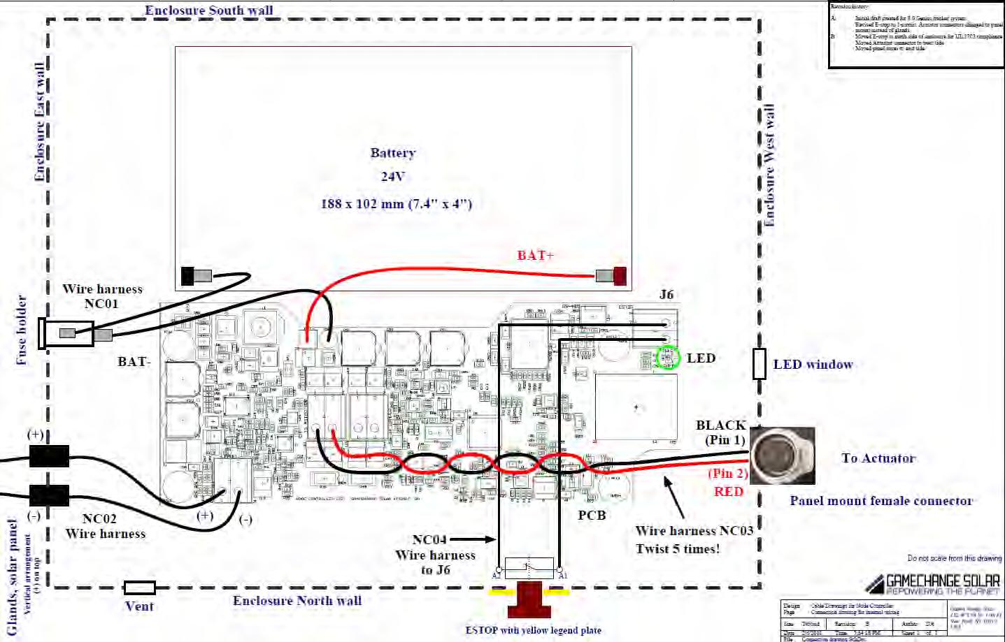
Master Controller Electrical Connections
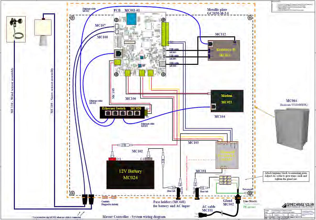
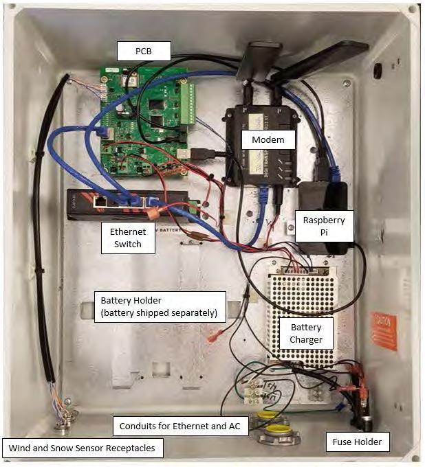
VI UNIT DIAGRAMS
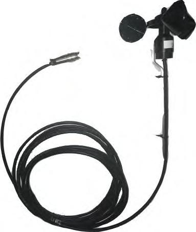
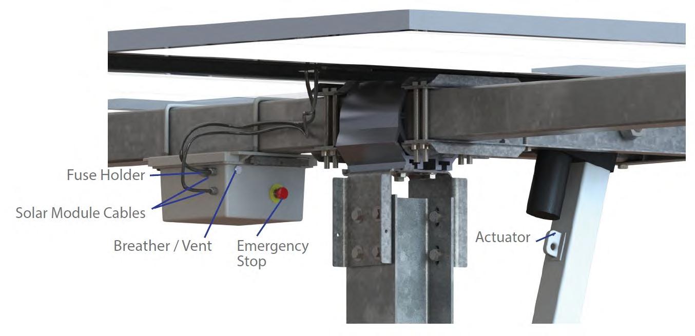
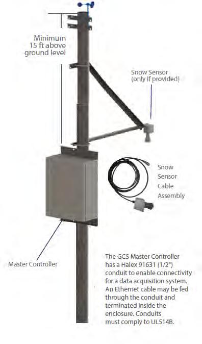
VII GENERAL OPERATION
Major Components
The Genius Tracker system is made up of the following major components:
Node Controller
Individual table controller. It is battery powered with a solar panel to charge the battery. The Node Controller powers the actuator to move the table to track the sun. It uses an accelerometer to measure its angle and an algorithm to calculate the angle of the sun.
Master Controller
Collects data from the Node Controllers and makes it available for data acquisition. It also can control the Node Controllers, having them go to various safe positions or different modes. This communication is achieved through a wireless Zigbee mesh network where each unit can communicate with the master by passing its information along through the other Node Controllers. The Master Controller interfaces with the data acquisition system by Modbus over TCP.
Lightweight Mesh Network
Each Master Controller runs its own Lightweight Mesh (LwMesh) network. This is comprised of 200+ Node Controllers. Each Node Controller is uniquely identified by a serial number and assigned to a specific Master Controller. Any change in location of the Node Controllers must be noted and this information will be provided to GCS. Moving a Node Controller from one Master Controller to another will require reprogramming.
Actuator
Each Node Controller moves its tables by extending and retracting a linear actuator mounted to the table structure. The Node Controller drives the Actuator motor using an on/off duty cycle specific to the Actuator model and site. During Actuator run time, 24-volt output can be measured at the Actuator connector from the Actuator power cable. A blinking LED on the Node Controller indicates the tracker is energized and may move at anytime.
Tracking Logic
Algorithmic Tracking
The Genius Tracker™ calculates the angle of the sun based on the NREL Solar Position Algorithm (SPA). This algorithm gives the current angle of the sun based on the latitude and longitude of the system, the time and the date to an accuracy of +-0.0003 degrees. The calculation runs every minute. The system will track to be perpendicular to this angle as long as this is achievable without going outside of the max rotation of the system and without causing row to row shading. At night, the system rests at either full west if antishading is not enabled or slightly west of flat if antishading is enabled.
The time is determined by the Master Controller using an on-board real time clock (RTC). The time provided by the RTC is synced to a time server daily to compensate for any drift. The RTC is accurate to 3.5ppm, over 1 million seconds (11.57 days) it will drift no more than 3.5 seconds.
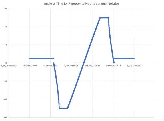
Antishading
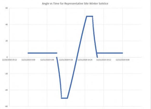
To avoid shading, the system will track to shallower angles when the sun is low. The system uses the row spacing and panel width to calculate the steepest angle possible without casting shade. This check is run each time the sun angle calculation is made. Adjustment for uneven terrain is made on a master by master basis by adjusting the row spacing to antishade more aggressively where necessary.
PowerBoost™
To optimize the antishading behavior of the system, the system can do a PowerBoost™ calibration to detect height differences from one row to another and factor this into the antishading behavior on a row to row basis. The nodes will use a calibration phase to detect shade transition using feedback from the charging panels, this will be used to determine height offsets. Once height offsets have been determined the antishading will be individually tuned for each row based on its height relative to its neighbors.
Battery Behavior
The battery is a 8Ah or 14Ah 24V Lead Acid Gel Battery.
To preserve the lifetime of the battery, the Node Controller limits its Depth of Discharge (“DoD”) to a configured limit. When the battery reaches its configured DoD limit it will go to flat and stay there until the battery is fully charged again. If the battery continues to drain, when it reaches its configured critical DoD limit it will move to wind safe position until it is fully charged.
In the event of malfunction leading to battery overcharging, the Node Controller will disable the charger circuit and send an alarm to the Master Controller. The Master Controller will then have the Node Controller move to a stow position with minimal charging until serviced.
Data Acquisition
Data acquisition is achieved using Modbus over TCP/IP.
The Master Controller will update information about the Node Controllers every half hour.Registers with information about the Master Controller (wind speed, time, snow depth etc.) will be updated continuously. The registers can be polled at a frequency of 5s.
The Node Controller reports information including current angle, battery voltage, and alarm information.
Remote Control
Remote control of the tracker system is available through the GameChange Web Portal.
The interface allows for setting the array to specific angles, sending begin tracking commands, getting real time data and updating the node list after replacements.
ThunderSmart™
GameChange Solar has worked extensively with CPP, the worlds leading wind engineering firm, to analyze and quantify the behavior of the tracker in various wind environments. One of the key outputs of that analysis is a stow strategy that limits the range of allowable tilt angles that the tracker can rotate within given the wind speed onsite at any given time. This is different than many of GameChange’s competitors as there is not one wind speed at which the trackers will go all the way to stow, but more of a sliding scale approach which maximizes energy harvest. For sites in jurisdictions with reliable weather forecasting services and which have the ThunderSmart™ functionality enabled, part of this strategy is to move the trackers to the west of flat if any of the following conditions exist to ensure safe operation of the trackers even against rapid ramp rates of the wind:
• Severe Thunderstorm Warning
• High Wind Warning
• Hurricane Warning
• Extreme Wind Warning
• Tornado Warning
• Tropical Storm Warning
• Wind Advisory
See the Stow Behavior Section on next page for more information.
Note: It is the responsibility of the owner and/or their O&M provider to integrate the ThunderSmart™ functionality into the site Scada system, to test for successful operation of the ThunderSmart™ functionality during commissioning, and to test the operation of the ThunderSmart™ functionality periodically during the operation of the power plant. The software for the ThunderSmart™ functionality is provided as-is without warranties of any kind either express or implied. GameChange cannot warrant the quality of weather forecasting nor ability of weather service to predict all high wind events.
Emergency Stop
If O&M staff onsite observe an unsafe condition, the red Emergency Stop (E-Stop) button on the tracker node controller may be pushed to stop that individual tracker from rotating. If the tracker is expected to remain stopped for a significant period and can be done so safely, it is recommended to rotate the table to the stow tilt angle shown in the project construction drawings using the provided Rotator Harnesses or manual Stow Controls prior to hitting the e-stop.
Detailed Stow Mode Descriptions
General Operation and Stow Prioritization
The control logic of the Genius Tracker™ System is designed to protect the tracker tables from a wide variety of potentially dangerous climatic conditions. The primary method of protecting the system is to restrict the range of motion to only the tilt angles that are safe given the current climatic condition. This restricted rotation is referred to as “Stow”. Note that stow overrides all normal tracking operations, including backtracking.
Each Genius Tracker™ System has a site-dependent “Full Stow Angle”. This Full Stow Angle is the most stable angle for the system and is the designed angle for enduring the most extreme weather events such as high wind or heavy snow. When the system enters full stow, the allowable range of rotation is limited to just the full stow angle.
The full list of possible stow modes is shown below. Each stow mode has a range of angles or a single angle (such as full stow or flat) defined depending on the conditions. The stow mode restricting movement to the angle closest to the Full Stow Angle will take priority to ensure the system is as safe as possible.
A Manual Override will take priority over all other stow modes regardless of angle.
Stow Modes in Order of Priority
1. High Priority Manual Stow
2. High-Speed Wind Stow
3. Hail Stow
4. Disconnected Wind Sensor Stow
5. Disconnected Snow Sensor Stow
6. Master Low Battery Stow
7. Snow Stow
8. Water Stow
9. ThunderSmart™ Stow
10. Low Priority Manual Stow
Detailed Stow Mode Descriptions
High Priority Manual Stow
I A High Priority Manual Stow will take priority over all other stow modes regardless of angle.
In the event that local weather forecasts predict a major wind, flood or snow event, move the system to stow. The system shall remain in stow until after the weather event and until after the site has been visually inspected. See the Preventative Maintenance section for more information.
Wind Stow
The Genius Tracker™ System is engineered to withstand maximum rated windspeed events at typically full stow angles of 35 degrees west or greater. In addition, there is a SmartStow™ technology which limits the range of rotation of the system to only those angles that are acceptable given the current wind speed. In this way, the tracker operating position remains as close to normal operating position for the time of day as possible to maximize production uptime while maintaining a sufficient level of safety against wind loads.
The Master Controller uses an anemometer to measure the wind speed. The Master Controller compares this to a lookup table of wind speeds and survivable angles. As the wind speed increases, the survivable angle is restricted to be closer to the Full Stow Angle. The Master Controller limits the tracking angle to be within the range of allowable angles as prescribed by the wind speed.
If the Master Controller has measured the wind speed and determined that the wind has crossed a threshold for one of the levels in its lookup table it will continue to restrict the tracking angle to the allowable range based on that threshold until the restore criteria has been met. To meet the restore criteria the wind speed must be below the trigger speed for the level that was triggered by the hysteresis amount (e.g. 10 mph less than the trigger) for a time dependent on the level of the threshold crossed, with 10 minutes being the minimum for returning to tracking and higher values (e.g. 1 hour) for higher wind speeds. Once the restore criteria is met for one wind level, the master drops down to the next level below it and must meet the restore criteria of that level to drop down to the level below it. This progressive restoring continues until the lowest stow level has been restored and the system returns to its full tracking range.
SmartStow™ is particularly useful in regards to the phenomenon commonly referred to as galloping. As the wind speed approaches the critical wind speed at which galloping is possible, the SmartStow™ technology will move the tracker tables out of an easterly or flat orientation to ensure galloping does not occur. However, if the system is already pointing towards the west, there will be little to no change to the tracker operation.
Furthermore, since the full stow angle is to the west and most wind events in North America occur due to thunderstorms
which occur in the afternoon, the tracker will already be at or near the Full Stow Angle during a high wind event. In this way the Genius Tracker™ System minimizes the impact of high wind events on tracker power production and reduces the time to rotate the tracker tables from the normal rotation angle to the Full Stow Angle.
Smart Stow Trigger Wind Speeds
Note: Wind shear reduces wind speed at anemometer (15 ft
Hail Stow
The Master Controller responds to hail stow commands. If the site is within the path of a forecast hail event the customer’s SCADA can order the Master Controllers to tell the Node Controllers to move the tracker tables to the maximum rotation angle (max tilt angle) to the west. GameChange has worked with multiple weather API providers to develop the means of predicting these hail events using their storm corridors. In this way the projected area of the solar modules for falling hail is minimized. Once the storm has passed through the site or the forecast is updated to no longer show the site within the path of the hail event the Master Controller instructs the node Controllers to resume normal tracking.
NOTE: It is the responsibility of the owner and/or their O&M provider to integrate the hail stow functionality into the site SCADA system, to test for successful operation of the Hail Stow functionality during commissioning, and to test the operation of the Hail Stow functionality periodically during the operation of the power plant. The software for the Hail Stow Functionality is provided as-is without warranties of any kind either express or implied, including damage to modules. GameChange cannot warrant the quality of weather forecasting nor ability of weather service to predict all hail events.
Disconnected Wind Sensor Stow
If communication with the wind sensor is lost, the Master Controller sends a stow message to all of the Node Controllers in its zone.
Disconnected Snow Sensor Stow
If communication with the snow/flood sensor is lost, the Master Controller sends a stow message to all of the Node Controllers in its zone.
Master Low Battery Stow
The Master Low Battery stow occurs after an AC disconnect, when the Master Controller is running on the back up battery. When the Master Controller’s back up battery begins to run low it sends the whole zone to stow.
Snow Stow
The Master Controller uses an ultrasonic distance sensor to measure the distance to the ground. As snow accumulates, the distance sensor reads a smaller distance to the perceived ground, which is the top of the snow. When snow underneath the sensor accumulates to a preset trigger height, typically 6 inches, the Master Controller tells the Node Controllers to move the tracker tables to the site-specific snow safety stow angle.
The operator must then determine that the snow level has decreased. This is done by visual inspection, either onsite or virtually. The snow level must have decreased to a preconfigured level less than the trigger height, typically 30% of the trigger height or 2” [50mm], and there must be 2” [50mm] or less of snow left anywhere on the panels. The operator can then send a Clear Snow Stow command through the WebApp or Modbus to resume normal tracking.
1. When all solar modules are clear of snow, the client can put the system into normal operating mode again by clearing all of the snow under the snow sensor in a 8 ft. diameter area.
2. Significant snowfall must be removed from all modules prior to putting the tracker back into operation. Ensure less than 2” of snow is on the modules before doing any clearing of the snow reading area under the snow sensors or else Actuators can be damaged and system could fail, voiding warranty. The 2” restore threshold will have a negligible impact on energy production as described in the Tracker Design Methodology Statement. It is not expected that this requirement will have a significant impact to plant output as research has shown that beyond 5 cm (2”) of snow depth, the albedo value of the snow mass is around 0.9 (see below figure). This means about only 10% of the total irradiation reaches the PV module, severely reducing the facility’s power generation. As such, a tracker system in operation will not generate a significant amount of additional electricity compared to the short amount of time the GameChange tracker in stow mode waiting for snow to slide off the panel after the weather event.

Snow Sensors must be properly maintained and calibrated or could cause false positives or negatives which could adversely affect production and void the warranty. It is the responsibility of the Purchaser and/or subsequent Warranty holder that snow accumulations of 6 inches or more is removed from the solar modules before the System resumes tracking. Further, accumulated snow must be cleared from the area under the modules and actuators where they rotate to at maximum rotation or modules and actuators could be broken from driving them into snow banks.
Water Stow
The Master Controller uses an ultrasonic distance sensor to measure the distance to the ground. As the flood water level rises the ultrasonic distance sensor reads a smaller distance to the perceived ground, which is the top of the flood waters. When the water level rises to the configured trigger height, the Master Controller tells the Node Controllers to move to the site-specific flood safety stow angle.
Once the flood level has decreased to a preconfigured level less than the trigger height, typically 30% of the trigger height, the Master Controller restores normal tracking.
WeatherSmart™
The Genius Tracker™ system responds to cloudy conditions in order to optimize the production of the system. Heavy clouds diffuse the sunlight. When the sun light passes through heavy cloud cover it scatters making the average direction of incident sunlight perpendicular to the ground instead of the angle at which it was originally coming in. This means that tracking to the sun angle wouldn’t produce more energy and it is more efficient to rotate the solar panels flat.
The system uses real-time weather data and forecast data from redundant weather services together with a proprietary GameChange Solar algorithm to determine if conditions are cloudy enough to go to WeatherSmart “Stow”. The system will only enter WeatherSmart™ stow when it is already flat, either at sunrise or at noon. This is to minimize wasted energy as the solar panels are already at the correct angle. At sunrise and noon, if the system detects that the conditions are cloudy enough, the command will go out to the Master Controllers and from there to the Node Controllers to hold the panels flat. The system will then check every 15 minutes whether the conditions are still cloudy enough to be in WeatherSmart™ stow. WeatherSmart™ Stow requires the level of cloud cover to be above the configured threshold at the time of polling and the forecasted level of cloud cover to be above the threshold for at least the next number of hours as configured. The threshold and number of forecasted hours are chosen based on GameChange research and development such that the system is responsive enough but does not chase diffuse lighting conditions in partly cloudy conditions.
ThunderSmart™
For sites in jurisdictions with reliable weather forecasting services that have the ThunderSmart™ functionality enabled, the trackers are stowed to the west of flat if storm conditions are detected.
Low Priority Stow
A low priority stow command can be sent to the Master controllers to instruct it to keep its Node Controllers to a specific angle. This command can be used for maintenance related work.
Cleaning Mode Stow
A master level stow that is used to set adjacent tables to alternating positions based on a user specified angle (E,W). Useful for cleaning the panels or mowing in between the rows.
Node Controller Stows
Estop Mode
If the emergency stop button on the Node Controller is pressed, the node immediately freezes in place. In order to resume normal tracking, the emergency stop button must be pulled out completely, and a tracking mode command issued.
Battery Low Voltage Stow
To preserve the lifetime of the battery, the Node Controller limits the Depth of Discharge (DoD) of the battery to a configured low battery limit. When the battery reaches a DoD greater than the configured limit it will restrict its movement to reach the flat position. Once it reaches the flat position it will stay there until the battery is fully charged.
To ensure the safety of the system, the Node Controller will move to the full stow angle for the system if the battery reaches a DoD greater than a second configured critical battery limit. This is to make sure the system arrives at the full stow angle before it discharges to a point where the battery would not have enough energy left to be able to reach the full stow angle. The Node Controller will stay at the full stow angle until it is fully charged.
The Node Controller measures its battery voltage every 30 minutes. This is used to determine the state of charge of the battery during discharging. Once a Node Controller goes into a Battery Low Voltage Stow condition it will continue to monitor whether or not it is fully charged based on the charge status of the battery charge controller which indicates a status for full charge based on the charge voltage and charge current.
Wrong Direction Stow
If the accelometer determines that the table is moving in the opposite direction from the direction it is supposed to be moving, the table is frozen in place, and the node controller is reset.
Battery Overvoltage Stow
If the Node Controller senses the battery voltage is too high it will shut down charging, halting the high voltage it is applying to the battery. It will also move the Full Stow Angle to ensure safety.
No Communication Stow
The Node Controllers communicate with the Master Controller via a zigbee wireless network. If the Node Controller has not received any communication from the master controller for 2 hours it will move to the Full Stow Angle.
IX REPORTING
Reporting Interval
The master controller collects data from the node controllers in 30 minute intervals. The nodes save their data on the hour and the half hour. The Master Controller begins collecting the data 1 minute later. During sleep periods (when the sun is not up) the Master Controller collects data on a 60 minute interval instead.
Angle Data
With each interval of data, the Node Controllers will report both their current angle and their target angle. The current angle is the accelerometer reading indicating its angle. The target angle indicates where the Node Controller is trying to move to. In most cases these will be close to the same as the Node Controller is generally stationary at the saving intervals.
Missing Data
In some cases, the Master Controller will not receive a current angle for a Node Controller while it is collecting data. This can happen because the Node Controller does not successfully communicate with the Master Controller or because the Node Controller doesn’t have a current angle saved when the Master Controller requests its data.
• In the case where the Master Controller was not able to communicate with the Node Controller the master will report its angle as 255.
• In the case where the Node Controller communicates with the Master, but the Node Controller has not saved its angle during the last interval (usually because of a reset) the Master Controller will report 256.
These values are outside the range of valid angles for the Node Controller and are used as indicators of missing data. In some cases, the Node Controller will not receive an angle from the Master Controller. In this case it will report its target angle as 180. This is an angle outside of the valid range and is used as an indicator of missing information.
All of these cases of missing information are accompanied by alarm states.
Alarm Data
The Node Controller and Master Controller each have various alarm conditions and status flags to indicate various states or faults.
Master Alarms
• AC Disconnect - a master level alarm that signifies the Master controller does not have AC power connected.
• Master Low Battery - a master level alarm that signifies that the master battery is below it’s voltage threshold.
• Disconnect Wind - a master level alarm that signifies that the wind sensor is malfunctioning or disconnected.
• Disconnect Snow - a master level alarm that signifies that the depth sensor is malfunctioning or disconnected.
• Overnight Stow - a master level stow that is triggered overnight to hold the trackers at a specified angle.
• Cleaning Mode Stow - a master level stow that is used to set adjacent tables to alternating positions based on a user specified angle (E,W). Useful for cleaning the panels or mowing in between the rows.
Node Alarms
• No Communication – the master did not receive a message from the node in the last interval
• Overcurrent – the node measured actuator current data above its current threshold (10A typ.)
• Battery Low - the node battery voltage is below the low voltage threshold (24.4V typ.)
• Battery Critical – the node battery voltage is below the critical voltage threshold (23.8V typ.)
• Tracking Disabled – the node has tracking disabled (triggered by a zigbee message or the estop)
• E-stop Pressed – the node’s estop is pushed in
• No Motion – the node tried to move and detected no motion
• Wrong Direction – the node tried to move and detected motion in the wrong direction
• Battery Overcharge – the node measured voltage at its battery above the overcharge threshold (30.7V typ.)
• Stow Enabled – the node was commanded to stow
• Node Charger Shutdown – the node shut down the battery charger because of bad charging conditions (temperature outside its range)
• No Data Available (Node) – Node has been reset since interval data was saved so has no data to report.
• Not Charging – Node is not charging the battery.
X USING THE MODBUS MASTER INTERFACE
Overview
The Modbus Master Interface is an application used for interacting with the generation 3 and 4 master controllers, especially when the GCS webapp is not available. The Modbus Master Interface gives the user access to system level configurations, real-time data, and a suite of commands for interacting with the tracking system.
Setup
The Modbus Master Interface (MMI) app is a portable program that does not require any installation and runs straight from the “dist” folder. Inside this folder you will find the app named “client_gui.exe” among some other folders and configuration files. All exported data (i.e. alarm list and parameter .CSV files) will be placed in this folder.
NOTE: It is important to keep the application and resource folder in the same directory for the execution of the program.
The MMI requires a network connection to communicate with the master controller and node network. To achieve connect to the master network, connect an ethernet cable from the field PC running the MMI app directly to the master controller’s ethernet switch.
Once connected to the master, the ethernet properties of the field PC must be configured properly to communicate with the master controllers on the network. The instructions below describe changing network settings on a Windows 10 device:
1. Open the Settings app by right-clicking on the WIFI symbol in the system tray and selecting “Open Network & Internet Settings” as shown below (Contact IT if does not have the privileges to change the network setting on your computer).

2. In the settings window, select the “Ethernet” subcategory from the navigation pane on the left and then select “Change Adapter Options” from the “Related settings” pane on the right.


3. In the “Network Connections” window, right click on the appropriate Ethernet connection and select Properties
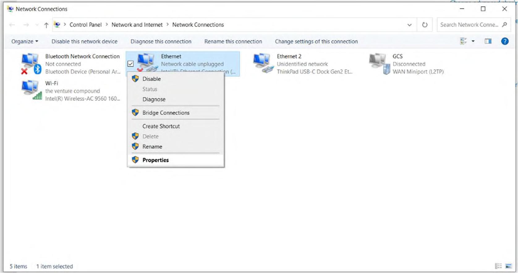
4. In the “Ethernet Properties” window, “Internet Protocol Version 4 (TCP/IPV4)” and click the properties button. In the “Internet Protocol Version 4 (TCP/IPV4) Properties” window, select “Use the following IP address” and manually set the address so that it is in range of the master’s IP. Click “OK” to save these settings. An example configuration is included below:
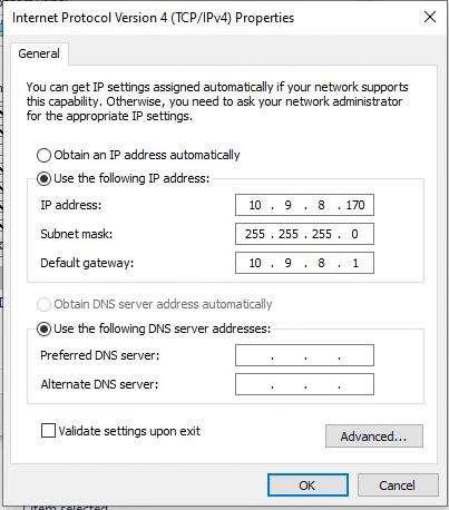
Note: If unsure about the proper ethernet settings, please contact the site’s GCS engineer.
5. After connecting to the master and configuring the field PC’s ethernet settings, launch the MMI app and wait several moments for it to open.
Using the Modbus Master Interface
Once the executable is run, an instance of the user interface will open alongside a black activity log window. From the “Connection” tab in the interface, the site-specific IP list is selected using the “browse file” button.

Once an IP list is selected, the connection is verified by selecting “test connection” and inspecting the log window. Masters that cannot be reached are removed from the working list. An example of a sitewide successful connection is shown below:

Master Status Tab
Various site information can be found in the “Master Status” tab.
Master Tab
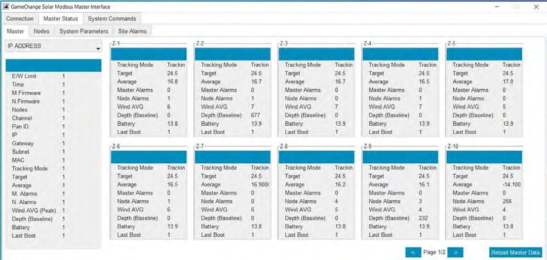
The Master subcategory of the Master Status Tab
The “Master” subcategory allows the user to load realtime tracking data from the entire site by pressing the “Load Site Data” button in the center of the window. If sitewide data is not desired, specific masters can be selected from the “IP ADDRESS” drop-down menu. Data can be refreshed with the “Reload Master Data” function.
Nodes Tab
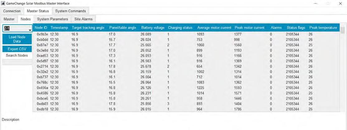
The Nodes subcategory of the Master Status Tab
The “Nodes” subcategory allows the user to fetch more detailed node data for a specific master.
After selecting a master from the “IP ADDRESS” drop-down menu, node data for the entire master can be collected by using the “Load Node Data” button. This data can be exported to a .CSV file with the “Export CSV” function. All exported data files will be generated in the same “dist” folder that contains the main executable file for the application.
System Parameters Tab
The “System Parameters” tab is not accessible in the customer version of this software. Please reach out to a GCS engineer if parameters need to be modified.
Site Alarms Tab

The Site Alarms tab
Sitewide node alarms can be loaded and viewed in the “Site Alarms” tab.
Alarm lists can also be exported as a .CSV file.
Issuing Commands from the System Commands Tab
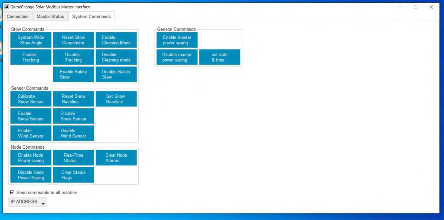
The System Commands tab
Commands can be issued to master controllers from the “System Commands” tab. Commands will be issued sitewide by default, but specific masters can be selected by unchecking the “Send commands to all masters” box and selecting a master from the “IP ADDRESS” drop-down menu.
Issuing a node command will prompt the user to provide a four-character node ID. Entering “0” for the node ID will issue the command to all nodes assigned to the selected master.
Descriptions of the various commands can be found in the following pages.
Stow Control Commands
Max West, West 35, West 25, West 5
Max East, East 35, East 25, East 5
Stow flat
System wide stow angle
Restore
Low priority stow
Low priority restore
High priority stow
Enable tracking
Disable tracking
OTA Commands
Set all nodes to specified west angle
Set all nodes to specified east angle
Set all nodes to flat stow
Manually set stow angle for all nodes (within east and west max)
Send node restore command
Send low priority stow command to node
Send low priority restore command
Send high priority stow command to node
Enable tracking node or entire network
Disable tracking for node or entire network
Command Description
Set overnight OTA conditions
Schedule overnight OTA
Cancel overnight OTA
Schedule nightly OTA check
Cancel nightly OTA check
Send configuration for overnight OTA conditions
Send command to schedule overnight OTA on the master
Cancel schedule overnight OTA
Send command to schedule a nightly OTA check
Cancel any scheduled nightly OTA checks
Sensor Commands
Calibrate snow sensor
Set snow baseline
Command Description
Calibrates the connected snow sensor with a new reading.
Sets the master’s baseline for the snow/water level.
Reset snow baseline Resets the master’s baseline for snow/water levels.
Disable wind sensor
Disables the wind sensor for up to 24 hours.
Enable snow sensor Enables the snow sensor functionality.
Disable snow sensor Disables the snow sensors functionalities.
Enable wind sensor Enables the wind sensor functionalities.
Node Commands
Command Description
Config/read node param Opens the node parameter configuration window for viewing and editing configuration settings stored on the master controller for the node controllers’ various settings. Clicking on an entry in the new window allows you to edit that field directly.
Reset node Resets the specified node.
Enable all node rebroadcast Enables Zigbee messages rebroadcast for all the nodes in the network.
Real-time Status Sends a Real-time status request to the specified node.
Clear alarm & status flags These fields are used to clear the specified alarm or status flag of the specified node. Enter the node ID into the box for either the alarm or status flag, and then click the dropdown menu to select which alarm or flag you wish to clear. After specifying the node id and selecting the alarm or status flag, click the “clear” button next to the status flag or alarm you wish to clear.
General Commands
Command Description
Enable master power saving Enables overnight power saving mode for the master controller.
Disable master power saving Disables overnight power saving mode for the Master controller.
Real-time call and response Initiates the real-time call and response on the node network.
Set date & time Sets the current date and time for the master controller.
Enable node power saving Enables the power saving mode for the node controllers on the network.
Disable node power saving Disables the power saving mode for the node controllers on the network.
Start call and response Starts a call and response to collect the interval data from the Nodes.
Config/read master param Opens the master parameter configuration window for viewing and editing configuration settings stored on the master controller.
Clicking on an entry in the new window allows editing.
XI RECOMMENDED TOOLS
The following tools are recommended to work on the Genius Tracker System.
1.
with AC/DC amp clamp.
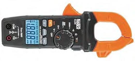
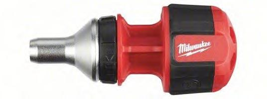


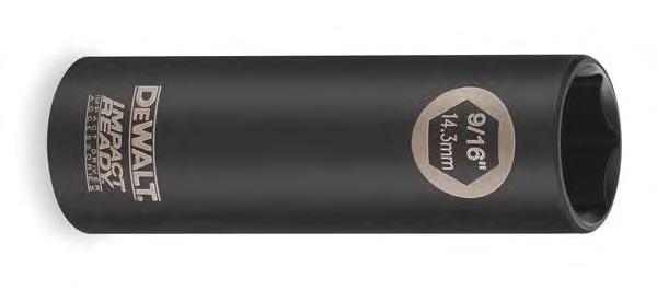


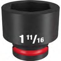


XII RECOMMENDED SPARES
Below are component failure rates along with spare part recommendations based on a 100 MW project.
1. GCS recommends you have 2-3 years of spares on hand as component malfunction may not perform perfectly linear.
2. Battery spares must be periodically trickle-charged during storage to prevent damage to batteries.
3. Does not include scheduled sitewide battery replacement.
4. Assumes 2,700 tables per 100 MW.
XIII PREVENTATIVE MAINTENANCE
Proper preventative maintenance must be conducted or warranty may be voided. For fast and easy maintenance on tracker, simply press Emergency Stop, disconnect actuator cable, and conduct maintenance. When completed, plug in actuator cable, release the Emergency Stop and contact GameChange or use Web Portal to resume tracking. As a safety precaution, in compliance with UL 3703, the system does not resume automatically.
I Proper preventative maintenance includes following the practices specified by AAMA 609 & 610-02 – “Cleaning and Maintenance for Architecturally Finished Aluminum” (www.aamanet.org) and equivalent standards for galvanized steel products. All installations in corrosive atmospheric conditions or areas of periodic submersion or ponding, or where components were subject to any ponding or moisture while still bundled prior to installation at the site, are excluded from the Warranty, at the sole discretion of GameChange.
I Notify GameChange immediately upon discovery of any potential or suspect defect at time of discovery. Any alteration, modification or repair of the system without written authorization from GameChange will void warranty. Any use of the system in a manner or for a purpose other than that specified by GameChange, or installed in any manner not specified by, or recommended against in, the installation manual provided by GameChange will void warranty.
I Preemptively stow tracker systems prior to any named storm or other event where design wind, flood, or snow loads, are expected to reach or exceed 80% of the design loads.
Inspect After Wind Event/Earthquake
A full O&M Inspection must be performed after the following events:
• Wind events reaching 80% of design wind speed
• Earthquakes reaching a magnitude of 4.0 or greater on the Richter scale
Inspect for Surface Rust
After installation of the Genius Tracker™ System, installer must annually monitor for any surface rust that may occur over time due to scraping of the components or for any other reason. While the extensive galvanizing protection should minimize any such rusting, it is essential that preventative maintenance be performed annually to include:
• Identifying any rust areas.
• Wire brush the rust area to remove all rust.
• Coat area with a cold galvanzing paint that has a dry film zinc content of at least 80%.
• This step is not required if rust is limited to edges which were cut during fabrication.
• If Capture Plates shows significant wear with visible groove (over 25% of thickness), capture ring shall be replaced.
Inspect for Wind Damage
After extreme wind turbulence (in excess of 80% of design wind speed), and on an annual basis, an inspection must be done for mechanical movement (which could also be due to other reason including thermal expansion and contraction). The frequency of inspection shall not be less than the following:
• 2% of tables are sampled at scattered locations throughout the array, never sample the same table twice in a threeyear period.
• If issues are discovered at more than 0.1% of the items checked in the 2% sample, an additional 8% will be sampled for a total of a 10% sample, never sample the same table twice in a three-year period.
• If additional issues are discovered at more than 0.1% of the items checked in the incremental 8% sample, then the entire site should be checked and remediated.
Inspect that Table is Straight
Check row tube is straight to Install Manual requirements. This may be measured using a pipe laser, transit, or similar method.
Inspect Bearings
Check bearing operation on each row to ensure there are no obstructions in the rotation of bearing and that bearing rotates freely.
Inspect Capture Plates
If capture plates shows significant wear (over 25% of thickness) with a visible groove, then they must be replaced.
Inspect Ridge Back Plates
• If ridge back plates show significant wear (more than 0.025” thickness loss) then they must be replaced.
• Ridgeback plates are designed to bear on center bearing collar.
• The Ridge Back Plates are expected to wear during the system operational design life and have been sized such that replacement is not expected.
Inspect Bolted Connections
• Thoroughly inspect connections for loosening of nuts and bolts. If any connections are found loose, re-torque to original torque specs.
• Inspect for and remove any ice or foreign material that may impede Actuator movement (linear and angular).
Inspect Connections to Modules
• Thoroughly inspect module hardware (clips, bolts, or rivets) to ensure modules are secure to racking.
• All clips shall be checked to make sure there is no gap between the side of the clips and the modules.
• All bolts and rivets shall be checked to ensure there is no gap between top of purlin and modules.
• Bonding straps secure (tube to tube, tube to post, post to actuator).
Cleaning and Site Maintenance
• Cleaning requirements will vary based on local conditions and individual owner maintenance programs. Area around the array must be kept clear of vegetation, debris, etc. that could impede movement or otherwise affect the array.
• Aluminum parts shall be maintained per AAMA 609 & 610-02 – “Cleaning and Maintenance for Architecturally Finished Aluminum”.
• Ensure strong chemicals with pH values below 6 or above 12 do not come in contact with the metal components.
• Do not connect parts made from dissimilar metals such as brass or copper, to the metal components without express written approval from GameChange.
• Annually monitor for any surface rust that may occur over time. Identify any rust areas, wire brush area to remove rust, and coat area with 80%+ zinc rich paint. This step is not required if rust is limited to edges which were cut during fabrication.
Inspect and Maintain Actuators
• Inspect housing, gearbox, and motor for damage or wear. Clean and repair or replace as needed.
• Ensure actuator is clear of ground or vegetation.
• Inspect actuator cable for signs of rodent damage or otherwise accelerated wear.
• Inspect actuator swivel mount on motor side of actuator. Apply lithium based anti-corrosion grease to actuator swivel mount on motor side of actuator every 5 years.
Inspect and Test Master Controller Sensors
It is recommended that you inspect and test the anemometer and Snow/Flood Sensor (if present) on a quarterly basis.
• Inspect Anemometer and Snow/Flood Sensor (if installed) to ensure no obstructions.
• Verify wind speed as reported by Master Controller using handheld anemometer.
• Place object directly below Snow/Flood Sensor to verify operation. Object must be at least 8 inches [200mm] tall, 24 inches [0.6m] wide and 24 inches [0.6m] long. Verify zone goes to Stow position. Remove object and verify zone returns to tracking.
Inspect for Scour
• Annually and after a major food event inspect the base of piles for signs of scour. Place clean sand in any holes deeper than 6 inches [150mm]. Fill holes until even with adjacent grade.
Check Pre-emptive Stow Functionality
It is recommended that you check the Preemptive Stow funtionality on a quarterly basis.
• Send test thunderstorm warning signal from Scada to master controller. Confirm zone goes to stow position. Clear test signal and verify zone returns to tracking.
• Annually and after a major food event inspect the base of piles for signs of scour. Place clean sand in any holes deeper than 6 inches [150mm]. Fill holes until even with adjacent grade.
SpeedClamp™ or Purlin Remediation
I CAUTION: Module removal may disrupt the bonding path and could introduce the risk of electric shock. Additional steps may be required to maintain the bonding path. Modules should only be removed by qualified persons in compliance with the instructions in this manual.
Prior to removing any SpeedClamp™ or purlin to which a braided jumper is connected, add a new braided jumper connecting the saddle bracket in the bonding path to an adjacent SpeedClamp™ or purlin that is not being removed. When the remediation work is complete, ensure a braided jumper is installed bonding the row tube to the saddle bracket to complete the bonding path from the tracker to a project grounding electrode.
XIV UPDATING NODE IDS
When the Genius Tracker System is initially set up during the commissioning process, and each time a node controller is added to the system or replaced, the Node IDs must be sent to the Master Controller so that they appear in the Master Controller’s list of registered Node IDs.
Syncing Node IDs from the GCS Web App
The Sync Node IDs (Master Controller Only) command on the CONTROLS tab of the Master/Node screen allows you to sync selected Master Controllers with the cloud storage for the GCS Web App, and download the Node IDs that were scanned in for those Master Controllers during the commissioning process.
To sync the Node IDs from the GCS Web App:
1. Select the Master Controllers to which you want to sync the Node IDs from the Select Master list. You can select a single Master Controller, or multiple Master Controllers, or click Select All to select all of the Master Controllers at the site.
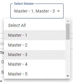
2. Select the Sync Node IDs (Master Controller Only) command from the Select Command list.
3. Click the Run Command button.
4. The Node IDs for the Node Controllers connected to the Master Controller, which were scanned in during the commissioning process, will be downloaded from the cloud and sent to the Master Controller, which then stores them in persistent memory.
5. Check the output from the command that appears underneath the RUN COMMAND button to determine if the command ran successfully.
Using the Node Replacement Wizard in the GCS Web App
It is sometimes necessary to replace a Node Controller module, due to hardware failure or environmental hazards. Because the Node ID is hardcoded into each node controller, when you replace the node controller, you must also change the Node ID in the system.
The Node Replacement Wizard allows you to update the Node ID in the system, watch the feedback as the new node is set up, and confirm the table is operational before walking away.
The Node ID of each Node Controller is a 64-bit ID number assigned to the node controller at the factory. This number is printed as a barcode on the label of the node controller.
To run the Node Replacement Wizard:
1. In the Site View Screen, click on the Node Replacement Wizard icon located along the upper right edge of the screen.
The Node Replacement Wizard appears.
2. Under 1. Input Old NodeID, type the Node ID of the old Node Controller into the Search by Device ID field, or click the symbol to scan the ID from the barcode on the Node Controller label using the camera of your mobile device.
3. Click the Next button to proceed to Step 2 of the wizard.
4. Under 2. Input New Node ID, type the Node ID of the new Node Controller into the Node ID field, or click the symbol to scan the ID from the barcode on the Node Controller label using the camera of your mobile device.
5. Click the Start Replacement button to run the wizard, which will then do the following without any further input:
• Change out the Node ID in the GCS Web Application.
• Upload the change in Node IDs to the online database in the cloud (Step 3).
• Push the updated list of Node IDs to the Master Controller (Step 4).
• Watch the feedback as the new Node Controller receives commands from the Master Controller and begins tracking (Step 5).
• Run a real time request to the node to confirm that the node has been set up and is operational (Step 6).
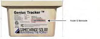


Pushing Node IDs From The Modbus Master Interface
Push IDs (sometimes refer as Sync Node Ids, Push Radio IDs, or Push Node Controller IDs) is a command that needs to be sent to the Master every time a new node ID is scanned in the GCS App.
Push IDs Process Overview

Downloading NodeIDs from the Web App
To download the latest scanned NodeIDs from the GCS App:
1. Select the specific site you are working on. For this example, Florida Warehouse is the site we want to Push new IDs.
2. Select “Alarms” at the top of the screen to view the dropdown menu.
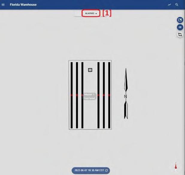
3. Select “Device Assignment.” to make the three dots circle appear on the right side of the screen.
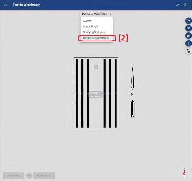
4. Select the three dots icon on the right side of the screen.
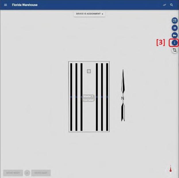
5. Select “Download All NodeIDs” This will download the file to your computer.

6. Once the download is complete. Click on the arrow to view “Show in Folder.”
7. Select “Shown in folder” from the menu to locate the file you just downloaded.
8. A new window, will pop up showing the files in your Downloads folder. This file has a naming convention of “NodeIDS*SiteName*date_time*. txt” and is typically the most recent file you just downloaded. Drag that file into the “dist” folder.
NOTE: Make sure to always have the latest Node IDs text file in this folder to avoid pushing old IDs to the master.
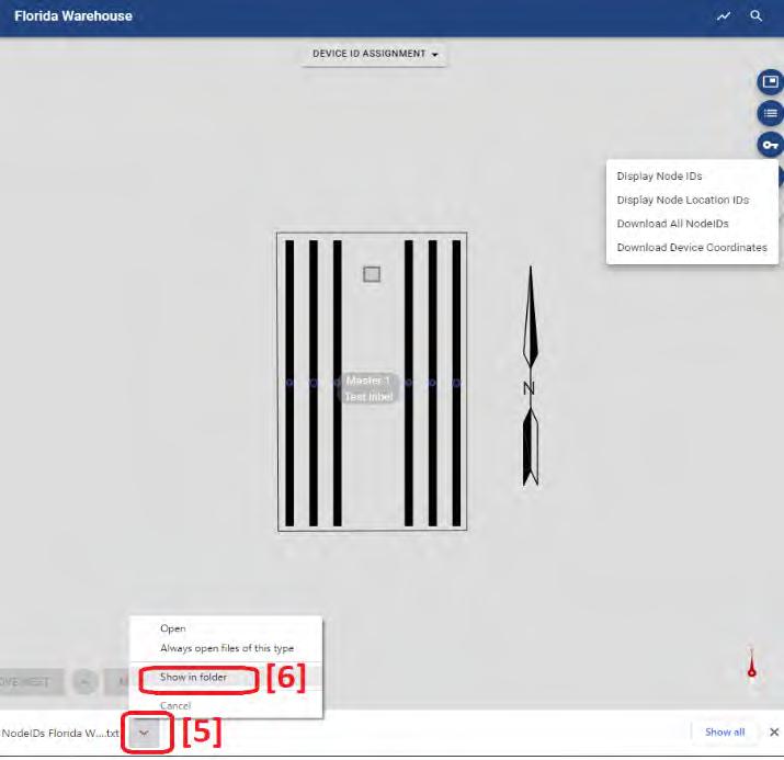
Pushing Node IDs to the Master Controller
The Node IDs can be sent to the Master Controller using the PushIDs command in the System Commands tab of the MODBUS Master Interface.
To push the Node IDs to the Master Controller:
1. Run the MODBUS Master Interface.
2. Select the System Commands tab.
3. Uncheck the “Send commands to all Masters” option in the top right corner of the screen.
4. Select the Master you are trying to PushID to from the dropdown menu.
5. Select “Push node IDs” A new Window will appear that allows you to select the Node file you downloaded from the GCS App to the “dist” folder.
6. Select “all files (*.txt*)” to view the text you dragged earlier.
7. Double left click the text file to select the PushID text file. This will automatically upload the new node IDs to the master.
8. Check MMI’s command prompt to make sure the NodeID command was successful. You should see “Node push SUCCESS.”

9. Send the “Clear Status Flags” command
10. Send the “Clear No Node Alarms” command.
11. Send the “Enable Tracking” command.
12. Verify all commands went through.
XV TROUBLESHOOTING GUIDE
To troubleshoot alarms at the node level, please make note of the alarm state of the tracker in question and follow the corresponding troubleshooting flowcharts on the GCS web app (https://app-next.gamechangesolar.com) . These flow charts will ensure the proper troubleshooting steps are taken and will also trigger the RMA process for the faulty material removed. To reach the troubleshooting flowchart, click on the node in question on the web app, then click the pop-up window and move to the troubleshooting tab.
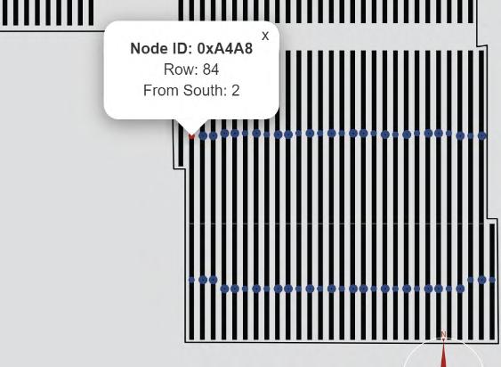

Using the GCS Web App Troubleshooting Wizard
The troubleshooting wizard provides a step-by-step troubleshooting walkthrough for a user onsite. Based on the type of alarm in the node details, the user directed through a remediation process for that specific type of issue. All the troubleshooting details and measurements done for a table troubleshooting are backed up in a cloud server where the web portal is hosted. At the end of the troubleshooting if a component was replaced, an RMA number is provided that begins the RMA process outlined in the GCS OM document.


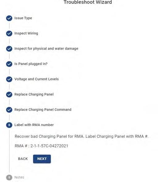
System Not Tracking
Use the following flowchart to diagnose and resolve a condition that prevents the system from operating in algorithmic solar tracking mode.

Charging Issues
Use the following flowchart to resolve issues preventing the Node Controller from charging its battery, triggering a Not Charging alarm.
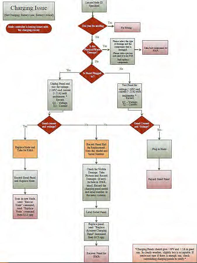
Battery Issues
Use this flowchart to resolve battery alarms such as Battery Low, Battery Critical, and Battery Low During Motion
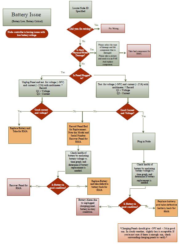
No Communication
Use this flowchart to resolve commmunication isses that trigger the No Communication and/or No Data Available alarms.

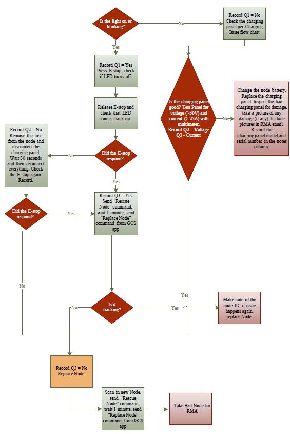
Battery Overcharge Shutdown
Use the following flowchart to resolve issues that could trigger the Battery Overcharge Shutdown alarm.
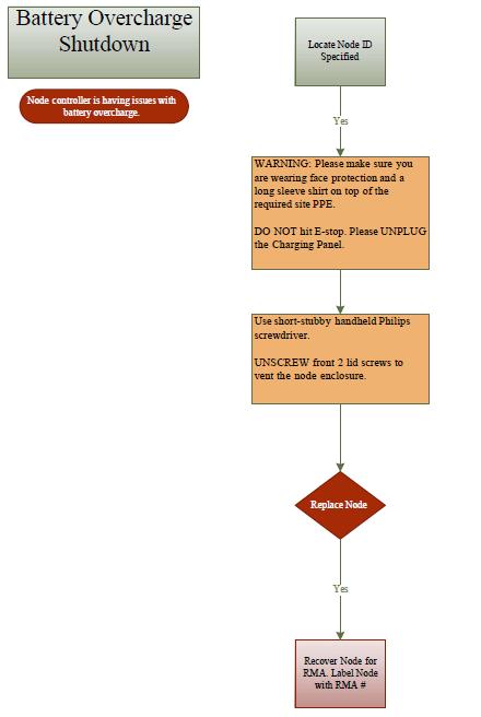
Anemometer (Wind Sensor) Installation Issues
Some anemometers have been installed without having looped the Cat5 cable through the 2nd and 4th cable ties on the mast. This places tension on the cable, all the way up through the hole in the sensor housing, resulting in the cable sheathing being pulled out of the housing. Then, water and debris get inside the cable and run downward, corroding the terminals inside the Master Controller enclosure, causing a short-circuit and failure.
When installing an anemometer, the technician must ensure that:
1. The top of the cable sheathing is fully inside the sensor housing.
2. The cable is looped and secured as to take strain off the top section of cable.
3. The terminals at the bottom of the cable, and inside the master controller enclosure, are clear of any build-up/corrosion.
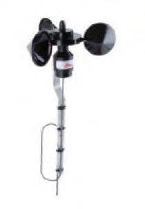
Anemometer Cable Repair
If a technician observes that the cable sheathing has been pulled out of the sensor housing, shown in Figure 3, then the sensor should be repaired using the following procedure:
1. Unscrew the anemometer cable from the GCS master controller to cut power to the sensor.
2. Detach the sensor assembly (sensor and aluminum holder) from the pole and bring it down to the ground.
3. Use a phillips head screwdriver to unscrew the bottom of the sensor housing, as shown in Figure 4.
4. Use a flat head screwdriver to detach the wires from the terminal block and shorten the wires just enough so that when re-assembled, the cable sheathing will not hang lower than the sensor housing O-ring.
5. Re-attach the wires to the terminal block, referencing Figures 4 and 5, and close the sensor housing, ensuring that the cable sheathing is completely enclosed with no opening for water or debris.
6. Using a wire brush, clear any corrosive build-up present on the terminals where the sensor cable enters the MC enclosure. Reference Figure 6.
7. Resecure the anemometer assembly on top of the pole.
8. Plug the cable back into the master controller.
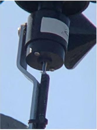
Node Battery Replacement Procedure
I Before servicing the tracker controller or actuator, always press in Emergency Stop first.
NOTE: The Node Controller does not need to be dismounted from the Row Tube when replacing the battery.
1. Unplug the actuator cable.
2. Unplug the charging panel cables.
3. Open the Fuse Holder and remove the Fuse.
4. Locate the battery door on the left side of the node enclosure when facing the main label. The battery door features a large red warning label. See Picture A - Battery Door.
5. The battery door is held shut by a latch on the bottom of the door. Squeeze the latch handles together in the center to release the latch and open the door. See Picture B - Door Latch
6. Remove the battery door by swinging it out and pulling it down. There are two tabs at the top of the door that hold it in place. See Picture C - Door Tabs. Set the door aside.
7. If a Battery Strap is present, unscrew the screws holding it in place.
8. Remove the old Battery, being careful not to damage the wires connected to the terminals. See Picture D _ Battery Terminals
9. Unplug the wires connected to the Battery terminals by pulling off the quick-connect tabs.
! - Tip: wiggling the tab connectors back and forth can help to free them.
10. Set the old battery aside for recycling.
11. Orient the replacement battery in the same position as the old battery.
12. Connect the battery wires to the new battery terminals, making sure to connect black to black and red to red.
13. Place the new battery inside the node enclosure.
14. If a Battery Strap was present, reinstall it by screwing the screws back into the holes for the Battery Strap.
15. Replace the battery door by placing the upper tabs into position, and then pivoting the door closed so that the latch on the bottom goes back into place and clicks shut.
16. Reinstall the Fuse and tighten down the Fuse Holder.
17. Plug the Charging Panel cables back in.
18. Plug the Actuator cables back in.
19. Release the Emergency Stop.
20. Re-enable tracking using a Modbus command or the GameChange app.
21. Please recycle the old battery.

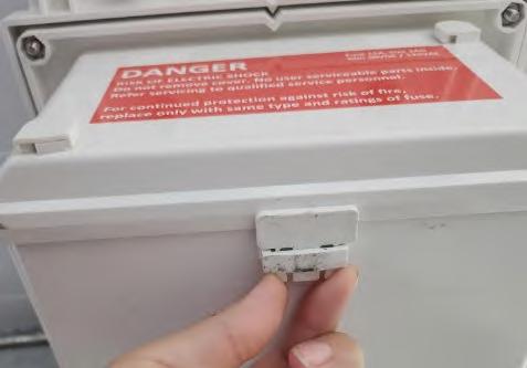
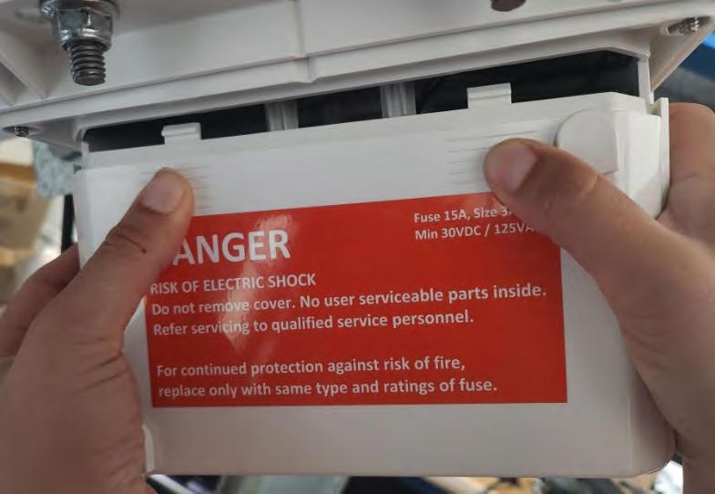
Malfunctioning Tracker Table Repair Procedure
I If there is a tracker table that stops properly functioning (monitoring reveals that either a tracker table is not tracking sun properly or not stowing properly during wind or snow event which should trigger stow) an immediate service visit should be conducted to restore the tracker table to normal operation to avoid any loss of power production from the array, or damage to the system.
Resetting the Master Controller
To troubleshoot a tracker table, start by cycling the power to reset the Master Controller:
1. Remove both the AC and DC fuses from the bottom of the Master enclosure
2. Wait 60 seconds
3. Install the AC and DC fuses back into their holders.
Contacting the GCS Field Application Engineer
If the steps above did not fix the issues you are seeing, please contact the Field Application Engineer responsible for your site to further troubleshoot the issue.
Inspect Tracker Table for Mechanical Issues
Prior to replacing tracker components, always check tracker table mechanical elements for straightness, tracker obstruction, misalignment, or damage. Also look for seized, twisted, or damaged bearings or bearing assemblies. Repair any mechanical deficiency prior to replacing tracker components (controller, charging panel, or actuator).
Stow Tracker Table
If tracker table is to remain stationary, set the table to the site-specific stow angle.
I Never leave a non-functioning table at any other position than the site-specific stow angle. Damage to the system as a result of a non-functioning tracker table left at a position other than the above mentioned stow angle is not covered under warranty.
GameChange Solar Repair Equipment
Specialty equipment available from GameChange Solar required to repair malfunctioning tracker:
1. GCS Table Rotator
Alarm States
Please see below for a description of different alarm states:
Alarm Description
Emergency Stop
This alarm indicates that the E-stop is pressed in, release estop and send begin tracking command
Overcurrent This indicates that the Node Controller detected something blocking its movement. The tracker must be inspected to ensure there is nothing obstructing the movement, if there is something blocking the tracker it must be removed,then the alarm can be cleared.
No Movement This indicates the Node Controller tried to move but detected it couldn’t. This often indicates a problem with the actuator. The table should be inspected, if there are no issues or the issues are fixed this alarm can be cleared.
Moved Wrong Direction This indicates that the Node Controller has detected movement in the wrong direction. The wiring could be wrong. The controller or the actuator might need to be replaced.
Low Battery The battery has reached its configured DoD limit and the tableis going to flat to recharge.
Critical Low Battery Alarm This indicates a critically drained battery; Node Controller will move to its wind safe position until it recharges.
No Communication Alarm This indicates the Node Controller didn’t successfully communicate with the Master Controller on thelast round.
Overcharging Alarm The Node Controller detected a fault in the charging circuit and the tracker will be stowed awaiting servicing.
Stow Enable Alarm The Master Controller has sent a stow command.
Tracking Disabled Alarm Triggered by default on power-on, preventing automatic movement. Can be cleared only from the Master Controller.
Diagnosis and Repair
Carry out the following steps to diagnose and repair a malfunctioning Genius Tracker table:
I Note: Before replacing any tracker component, always press in the emergency stop on the node first.
1. Check the Fuse
1. Check the node controller fuse to make sure it is not burned out and is installed properly. Replace fuse if burned out.
2. Check the Actuator.
1. Press in Emergency Stop, disconnect Actuator connector from Controller.
2. Connect actuator to GCS approved Table Rotator. If necessary, charge the Table Rotator according to its instructions.
3. Ensure good electrical connection to actuator.
4. Ensure that the actuator can be operated in both directions. To prevent overheating, the actuator duty cycle must not exceed 10%. The maximum duration running continuously is 2 minutes, which requires a cool-down of 18 minutes.
5. If motor does not run, replace Actuator with new Actuator (see replacement procedure below), and plug into Node Controller.
6. Release Emergency Stop.
7. Contact GameChange or use Web Portal to clear alarm so that tracking can resume.
3. Check the Charging Module.
1. Press in Emergency Stop.
2. Measure voltage on Charging Module. Unplug MC4 connectors and measure voltage across MC4 connectors while Charging Module is facing full sunlight. Verify voltage is within Charging Module specification on label.
3. If there is no voltage or voltage is very low, replace Charging Module. Charging Modules vary by site. See data plate on back of charging module for site specific voltage and current.
4. If voltage is within module specification, check current flow from Charging Module. Plug both Charging Module connectors into Controller. While sun is shining on Charging Module, place a DC clamp meter around one of the Charging Module wires. Be certain to only clamp one wire, and be sure to use a DC clamp meter. Use a DC clamp meter such as the Extech AC/DC clamp on meter or the Fluke 325 True-RMS Clamp Meter to verify current flow is within Charging Module specification on label.
5. If there is no current flow, replace Charging Module. Charging Modules vary by site. See data plate on back of charging module for site specific voltage and current.
6. After replacing Charging Module and plugging into Controller, set the table to horizontal and allow the Charging Module several hours in sunny conditions to charge the battery and resume tracking.
NOTE: Do not set the table to horizontal in high winds or stow events, as this may damage the components and void warranty.
7. Release Emergency Stop.
8. Contact GameChange or use Web Portal to clear alarm so that tracking can resume.
4. Reset the Controller.
1. Unplug the solar panel cables.
2. Unscrew the fuse and remove it.
3. Wait 30s.
4. Screw the fuse back in and ensure it has a good connection.
5. Plug the solar panel cables back in.
6. Contact GameChange or use Web Portal to clear alarm so that tracking can resume.
5. Replace Controller. If none of the above procedure correct the problem, replace the Controller.
1. Press the Emergency Stop.
2. Turn off the Controller by removing the fuse and disconnect the charging module.
3. Unmount the old Controller and mount the new controller.
4. Note the old and new Controller’s ID (see labels) and contact GameChange to introduce the new Node Controller to the array.
5. If available, fill out the failure log or provide all relevant information to GameChange personnel for bookkeeping.
6. Power up the new Controller by inserting the fuse.
7. Plug in the actuator and charging cable.
8. Release the Emergency Stop.
9. Contact GameChange or use Web Portal to clear alarm so that tracking can resume.
Actuator Cable Remediation
If the cable between the Actuator and the Node Controller is damaged the following procedure can be used to remediate the cable in the field. Do not perform Actuator Cable Remediation in windy conditions (sustained wind or sustained gusts in excess of 20MPH).
I Ensure Emergency Stop on Node Controller is pressed in prior to performing any work on tracker table.
1. Unplug Actuator cable from Node Controller using plug removal tool.
2. Cut cable on either side of the damaged section of cable. The removed section of cable can be up to 6” long.
3. Connect ends of good sections of cable using a splice kit as follows. Splice kit must be IP68, min 15amp rating, Ø 5mm-12mm, UL Listed (example below).

4. Insert end of good section of cable through splice kit grommet.
5. Strip away 1” of black cable insulation.
6. Strip ½” of the ends of red and black wires for insertion into splice kit terminals.

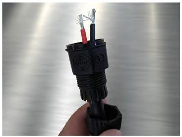
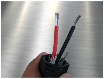
7. Insert conductors of black and red wires into respective terminals in splice kit and torque to splice kit manufacturers specs using small screw driver.
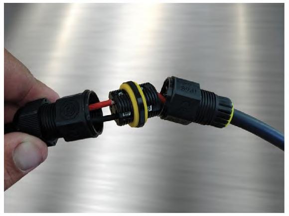
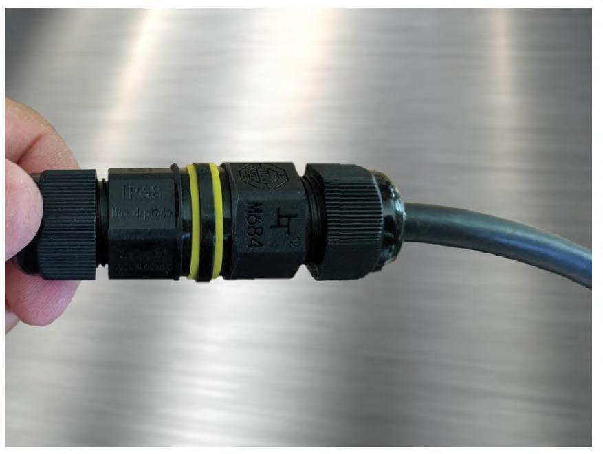
8. Repeat steps 1 through 7 for other good section of cable on opposite side of splice kit.
9. Ensure wires are installed in proper terminals to maintain polarity.
10. Plug Actuator cable into proper terminal in node controller.
11. Release Emergency Stop Node Controller. Contact GameChange or use Web Portal to clear alarm so that tracking can resume.
12. Confirm Actuator moves per normal operation before leaving site.
Actuator Replacement Procedure
I Do not perform Actuator replacement in windy conditions (sustained wind or sustained gusts in excess of 20MPH).
I Ensure Emergency Stop on Node Controller is pressed in prior to performing any work on tracker table.
To replace the Actuator:
1. Unplug and disconnect actuator from Node Controller.
2. Measure center point on drive arm for pilot hole to be drilled for actuator replacement tool. (See A.1)
3. Drill pilot hole with a 1/8 drill bit. (See image A.2)
4. Use 3/4 stepper bit to widen pilot hole to slightly over ½” (see image A.3)

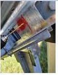
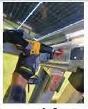
5. Assure pilot hole is correct size to fit ½“ Bolt for actuator replacement tool (See A.4)
6. Push bolt through drive arm allowing threads to be present outside drive arm. (See A.5)
7. Attach replacement tool to bolt (See A.6)
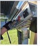

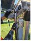
8. Secure actuator replacement tool by threading the nut to the bolt. (This allows to adjust the angle of the replacement tool if need be.) (See A.7)
9. Extend actuator replacement tool by holding bottom spindle stagnate and rotating clockwise. (See A.8)
10. Attach bottom bolt into prefabbed hole on bottom bracket. (See A.9)
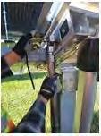
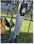
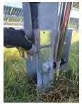
11. Secure actuator replacement tool by threading the nut to the bolt. (See A.10)
12. Once both bolts are secure. Rotate the actuator replacement tool clockwise to allow tension to build between the drive arm and bracket. (This will assure the table does not move when removing the actuator.) (See A.11)
13. Remove grounding strap with 7/16” wrench or socket. (See A.12)
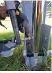
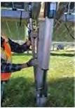

14. With a 1_11/16” open box wrench, secure the bottom bolt from rotating freely. With a 1_11/16” socket attached to a ½” drive breaker bar, remove the nut from the bottom bolt. (See A.13)
15. Assess the bottom bracket to find a gap between the bolt brackets. Use the table turner and follow the gap until bottom actuator bolt has released tension. Allowing the bolt to be removed. (See A.14)
16. Remove bottom bolt from the actuator and bracket (see A.15)
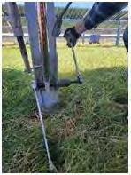
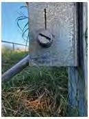

17. With a 1_11/16” open box wrench, secure the top bolt from rotating freely. With a 1_11/16” socket attached to a ½” drive breaker bar, remove the nut from the top bolt (See A.16)
18. 18.0 Remove with top bolt allowing the actuator to become free of the table. Team lifting is preferred. One person will begin to remove the bolt as the second person lifts and removes actuators from the drive arms. (See A.17)
19. 19.0 Once actuator is free of the drive arm. Set in secure location for RMA/RCA process. (See A.18)
20. Once actuator is removed. Begin the steps in reverse.
21. Team life installing the new actuator. One person lifting actuator, while the second person secure the bolt through the drive arm. (See A.19)
22. With a 1_11/16” open box wrench, secure the top bolt from rotating freely. With a 1_11/16” socket attacked to a ½” drive breaker bar install the nut for the top bolt. (See A.20)
23. When installing the bottom bolt for the actuator. Assure the plastic spacers are install in between the inside of the bottom bracket and the actuator (See A.21)
24. With a 1_11/16” open box wrench, secure the bottom bolt from rotating freely. With a 1_11/16” socket attacked to a ½” drive breaker bar, install the nut onto the bottom bolt. (See A.22)
25. Reinstall the grounding strap from new actuator to existing drive arm. With 7/16” wrenches or socket. (See A.23)
26. Use a table turner to remove tension from the actuator replacement tool by extending/retracting the actuator and following the gap where the replacement tool is attached to the drive arm. (See A.24)
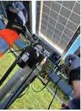

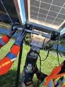
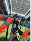


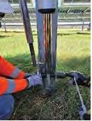


27. Remove bottom bolt of actuator replacement tool (See A.25)
28. Retract actuator replacement tool by holding bottom spindle stagnate and rotating counterclockwise. This will allow both ends to retract collectively. (See A.26)
29. Remove top bolt of actuator replacement tool, allowing tool to become free of drive arm. (See A. 27)
30. Begin RMA Process.


Charging Panel Test Procedure
I Do not perform Charging Panel replacement in windy conditions (sustained wind or sustained gusts in excess of 20MPH).
I Ensure estop on Node Controller is pressed in prior to performing any work on tracker table.
To perform a test of the Charging Panel:
1. Ensure the connection to node is secure. (B.1)
2. With a mc-4 removal tool, disconnect the charging module from the node controller. (B.2)
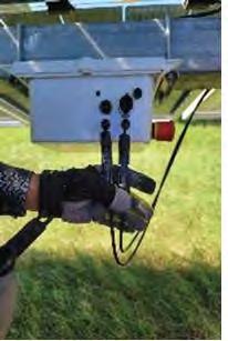

3. Unplug the charging panel from node and test is open circuit voltage (VOC) and its short circuit current (ISC). 36-60 VOC and .25-2 ISC in direct sunlight and sunny conditions. (B.3)
4. Connect charging modules mc-4’s together to complete the circuit and test the short circuit current (ISC). (B.4)
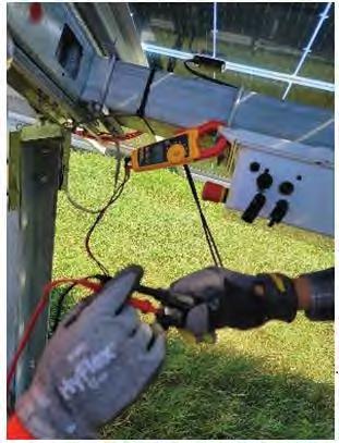

5. Disconnect charging module MC-4’s. (B.5)
6. Reconnect charging module to node controller. Ensure a secure connection. (B.6)
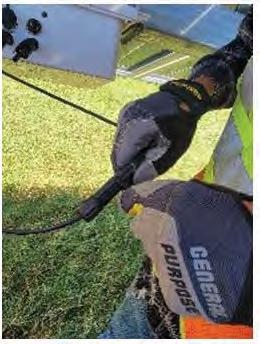
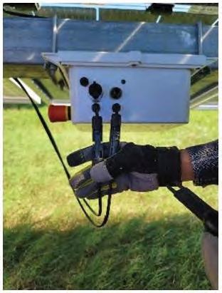
Charging Panel Replacement Procedure
I Do not perform Charging Panel replacement in windy conditions (sustained wind or sustained gusts in excess of 20MPH [10 m/s]).
I Ensure Emergency Stop on Node Controller is pressed in prior to performing any work on tracker table.
To replace the Charging Panel:
1. Unplug Charging Panel connectors from Node Controller using plug removal tool.
2. Unbolt Charging Panel from Wind Break Plate.
3. Install new Charging Panel in same orientation as original Charging Panel.
4. Torque hardware to specification per GCS Install Manual.
5. Plug Charging Panel wires into Controller, ensure connectors click, indicating secure connections.
6. Remove all tools and vehicles from tracker table, ensure there is nothing that could interfere with table movement.
7. Release Emergency Stop Node Controller. Contact GameChange or use Web Portal to clear alarm so that tracking can resume.
8. Safely package defective Charging Panel for shipping.
Node Controller Board Replacement Procedure
I Ensure Emergency Stop on Node Controller is pressed in prior to performing any work on tracker table.
Tools needed:
• Phillips head screwdriver (magnetic is recommended)
• Small flathead screwdriver or tweezers.
To replace the Node Controller board:
1. Open the box by unscrewing the 4 screws in the lid (C.1)
2. Unplug the Positive battery wire (C.2)
3. Unplug the negative cable from the bottom of the fuse holder (C.3)
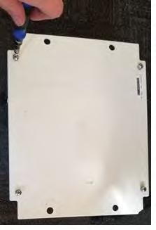

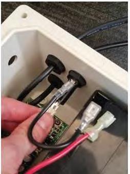
4. Use the small flathead screwdriver or tweezers to push in the springs in the spring terminal for the estop wires, then pull the estop wires out. (C.4)
5. Use the small flathead screwdriver or tweezers to push in the springs in the spring terminal for the motor wires, then pull the motor wires out. (C.5)
6. Use the small flathead screwdriver or tweezers to push in the springs in the spring terminal for the panel wires, then pull the panel wires out. (C.6)
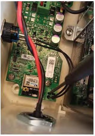
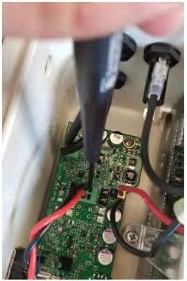
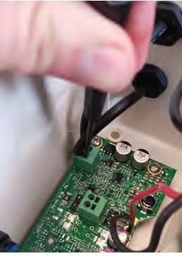
7. Use the Philips head screwdriver to unscrew the 4 screws in the board (C.7)
8. With the wires disconnected and the board unscrewed, remove the board from the box. (C.8)
9. Peel the node ID sticker off the box (C.9)
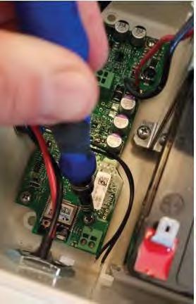
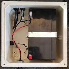
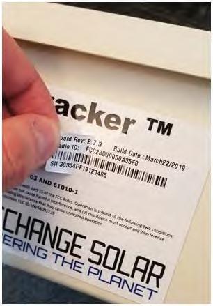
10. Wrap the label around the battery of the old board (C.10)
11. Remove the new board from the bag making sure to hold onto the label (C.11)
12. Place the node ID label for the new board on the box. (C.12)
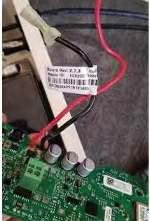

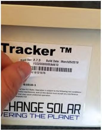
13. Insert the new board into the box (C.13)
14. Use the Philips head screwdriver to screw in the 4 screws to hold in the board (C.14)
15. Plug in the panel wires into the panel wire terminals, the wire from the lower port should go to the further terminal (C.15)

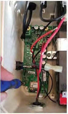
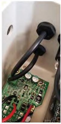
16. Plug the motor cables into the spring terminal for the motor cables, the red cable should be on the side closer to the LED window (C.16)
17. Using the flathead screwdriver or the tweezers to push the springs of the spring terminal, insert the estop wires into the spring terminal for the estop, the orientation is not critical (C.17)
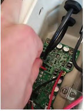

18. Plug the negative battery cable into the bottom terminal of the fuse holder, be sure to get the orientation of the connector correct. (C.18)
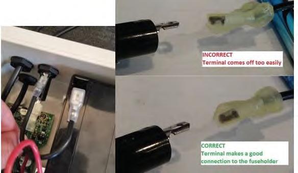
19. Plug the positive battery terminal onto the positive battery tab (C.19)
20. Close the lid using the 4 lid screws. (C.20)
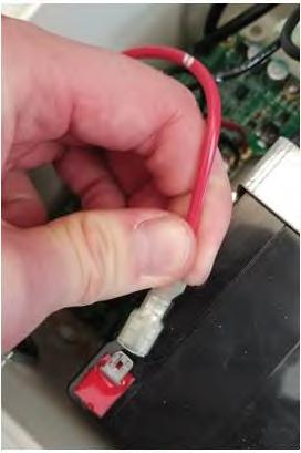

Adding a Node with a New Board to the Network
Method 1: GCS Application
1. Find the node which had the board replaced on the map (D.1)
2. Click on the node and then click on the label to bring up the node’s info, then click “configure” (D.2)
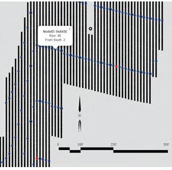
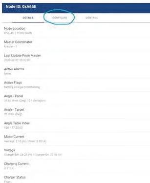
3. Click on the “replace node ID” button, the app will use your phone’s camera to scan the node id, position the node id label in the camera window. (D.3 & D.4)

4. Click on the “Control” tab for the node (D.5)

5. Send the “Rescue Node” command (D.6)
6. The rescue node command takes a minute to work. Use this time to hang the node.
7. Once the node is mounted, go back to the “Control” tab for the node.

8. Send the “Replace Node” command (D.7)

Method 2: Modbus Commands
1. Send the node ID of a neighboring node to the node with the replaced board to register 40055
2. Send the node ID of the new board to register 40056.
3. Send decimal value 4757 to register 40057.
4. Send decimal value 16 to register 40058.
5. Send 1 value to register 40059.
6. Confirm success by reading 2 and then 3 in register 40059.
7. Send the Node ID of the old board to register 40050, the label has the node ID in hexadecimal, the Modbus, command must be sent with decimal value.
8. Send the Node ID of the new board to register 40051.
9. Send value 1 to register 40052.
10. Confirm success by reading value 2 and then 3 in register 40052.
Node Replacement Procedure
The following procedure is for removing the entire Node Controller from the torque tube and replacing with a new replacement unit.
1. Press E-stop and use a flat-head screwdriver to remove the fuse-holder and remove the fuse (keep the fuse safe as you will be installing it in the new node being used for the replacement)
2. Disconnect actuator from node (E.1)
3. Disconnect charging module from node (E.2)
4. With a 9/16 deep socket, remove all four 9/16 nuts. (E.3)
5. This will allow for the purlin channel and node to be removed from the U-bolt. (E.4a & E.4b)
6. Reinstalling the node, will require to thread U-bolts through the eyelet of the node. (E.5)


7. Place the Purlin channel onto the U-bolts & secure with a 9/16 nut. (E.6a & E.6b)
8. Once all four 9/16 nuts is finger tight. Secure them to the U-bolts with a 9/16 deep socket attached to an impact drill (E.7a & E.7b)

9. Use a flat-head screwdriver to remove the fuse holder and place the fuse from the previous node in the fuse holder and screw it back into the node.
10. Reconnect charging module to node controller (E.8)


11. Reconnect actuator to the node controller (E.9a & E.9b)
12. Make sure the e-stop is not pressed in and that the LED on the node is solid
13. Scan the new node barcode into the GCS web app

Battery Test Procedure
I Ensure Emergency Stop on Node Controller is pressed in prior to performing any work on tracker table.
1. Disconnect the charging module from the node controller with a mc-4 removal tool (F.1)
2. With a small handheld Philips screwdriver, proceed to remove the bolts disconnecting the node controller from the lid completely (F.2)
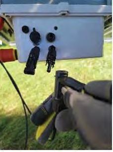
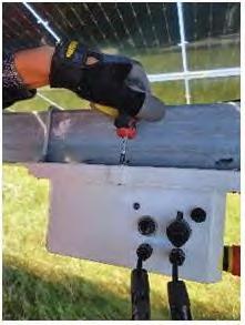
3. Test your battery voltage with a multimeter set to DC volts by touching the multimeter leads to the positive and negative terminals of the battery. Nominal voltage is 27v—24.04v. (F.3)
4. Connect charging module to node. Test your battery voltage with multimeter set to DC volts by touching the multimeter leads to the positive and negative terminals of the battery. Nominal voltage is 27v – 24.04v. (The voltage should exceed previous measurement when node was disconnected from the charging module). (F.4)

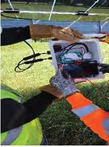
5. Reinstall node to lid by screwing in bolts to the node controller. Assuring all bolts are secure, making a flush connection from node controller to the lid. (F.5)
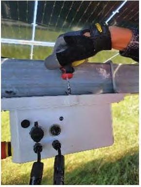
RMA Process
The following is a flowchart diagram of the RMA process.
Return Material Authorization Form
A APPENDIX FOR GEN4 NODE CONTROLLER
Introduction
The Gen4 Node controller is an update to the previous Node Controller, featuring a number of new features:
• New LCD display and front-mounted control panel for inspection and direct control of the node
• New LFP battery
• New node enclosure with access panel for battery replacement
• No external fuse
Power ON/OFF
The power button for the Gen4 Node Controller is located on the front control panel under the LCD Display.
If the Node Controller is not turned on, press the power button on the front control panel for three seconds to power on the Node Controller.
To power down the Node Controller, disconnect the charging panel and press and hold the power button for three seconds.
NOTE: The Gen4 Node Controller does not have an external fuse that needs to be installed before operating the controller.
The node controller will automatically turn itself on when the charging panel is connected.
If the Node Controller is powered on but the charging panel is not connected, and the node has not been commissioned, it will automatically turn itself off after two hours.
Triggering a Node Reset
To trigger a reset on the Gen4 Node Controller, press both the power and Mode buttons on the front panel for three seconds, then release.
Resetting CH and Pan ID to Default Settings
Press both the Mode and Info buttons on the front panel for three seconds to reset the Ch and Pan ID settings for the LwMesh network to their default settings.
Clear Alarms/Flags
To clear the node alarms and flags, press both the Mode and Select button for three seconds.
NOTE: This will not clear the Tracking Disabled or Battery Overcharging alarms.
Overcurrent Alarm Threshold
For the Gen4 Node Controller, the Overcurrent Alarm is triggered at a threshold of 8A.
Internal Backup Fuse
The Gen4 Node Controller contains an internal backup fuse that is mounted on the circuit board.
I The internal backup fuse should only be serviced by GameChange Solar personnel.

Front Panel Operations
The Gen4 Node Controller is equipped with an LCD display and a front control panel that allows technicians to inspect the state of the system and change operating modes.
The backlight on the LCD comes on when a button is pressed, and turns off automatically after 10 seconds of inactivity.
If there is no activity for 10 seconds, the front panel will return to its default display.
Front Panel LEDS and Their Meaning
The front panel has LED lights on each side of the LCD display. The left LED is red, and is the Alarm LED. The right LED is green, and is the Mode LED.
The meaning of the two LEDS is as follows:

The following operations can be performed from the front control panel:
View Home Screen (Default Display)
The Home Screen is the default display for the front panel LCD when no info display or operation is in progress.
The Home Screen displays the current operating mode and angle.
The front panel automatically returns to the Home Screen after 5-10 seconds if no other front panel functions are being used (i.e. no buttons are being pressed).
You can also return the front panel to the home screen by tapping the power button.
View Node ID
To view the mesh network Node ID of the node controller:
1. Click the Info button in the lower left corner of the control panel to access the information readouts.
2. Use the up and down arrows to find the View Node ID option and display the Node ID readout.
After 10 seconds, the LCD will revert to the default display.
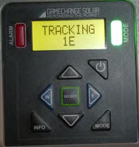

View Node Firmware Version
To view the version number of the firmware installed on the node controller:
1. Click the Info button in the lower left corner of the control panel to access the information readouts.
2. Use the up and down arrows to find the Node Software option and display the version number of the firmware.
After 10 seconds, the LCD will revert to the default display.
View Current Angle
To view the current angle readout:
1. Click the Info button in the lower left corner of the control panel to access the information readouts.
2. Use the up and down arrows to find the Current Angle option and display the current angle readout.
After 10 seconds, the LCD will revert to the default display.
View Goal Angle and Target Angle
The Goal Angle is the angle that the node is currently trying to move the table to. The Target Angle is the current ideal tracking angle as calculated by the Master Controller using the NREL Solar Positioning Algorithm.
To view the Goal Angle and Target Angle readout:
1. Click the Info button in the lower left corner of the control panel to access the information readouts.
2. Use the up and down arrows to find the Battery Voltage option and display the Goal Angle and Target Angle.
After 10 seconds, the LCD will revert to the default display.
View Battery Voltage
To view the battery voltage readout:
1. Click the Info button in the lower left corner of the control panel to access the information readouts.
2. Use the up and down arrows to find the Battery Voltage option and display the battery voltage readout.
After 10 seconds, the LCD will revert to the default display.
View LFP State of Charge
State of Charge is the percentage of the battery’s maximum charge that remains in the battery at present.
To view the State of Charge (SoC) of the LFP battery:
1. Click the Info button in the lower left corner of the control panel to access the information readouts.
2. Use the up and down arrows to find the LFP SOC option and display the LFP SOC readout.
After 10 seconds, the LCD will revert to the default display.
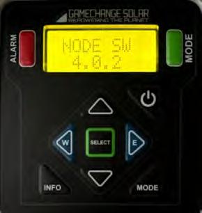
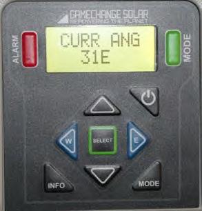
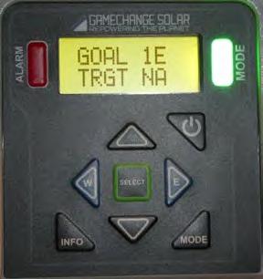

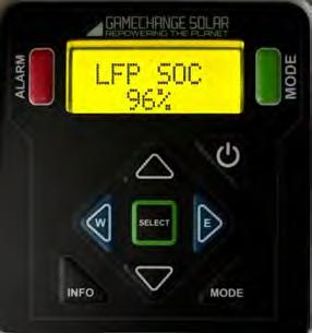
View LFP State of Health
State of Health is the percentage ratio between the current maximum capacity of the battery and its original rated capacity.
To view the State of Health (SoH) of the LFP Battery:
1. Click the Info button in the lower left corner of the control panel to access the information readouts.
2. Use the up and down arrows to find the LFP SOH option and display the LFP SOH readout.
After 10 seconds, the LCD will revert to the default display.
View the Charging State
To view the current stage of the battery charging process:
1. Click the Info button in the lower left corner of the control panel to access the information readouts.
2. Use the up and down arrows to find the Charge Stage option and display the charging state readout.
The possible values are Bulk, Float, Absorbtion, and No Charge
After 10 seconds, the LCD will revert to the default display.
View Charging Panel Voltage
To view the Charging Panel voltage readout:
1. Click the Info button in the lower left corner of the control panel to access the information readouts.
2. Use the up and down arrows to find the Panel Voltage option and display the charging panel voltage readout.
After 10 seconds, the LCD will revert to the default display.
View Panel Amps
To view the Charging Panel Amps readout:
1. Click the Info button in the lower left corner of the control panel to access the information readouts.
2. Use the up and down arrows to find the Panel A option and display the charging panel voltage readout.
After 10 seconds, the LCD will revert to the default display.
View Charger Software Version
To view the version number of the Charger Software:
1. Click the Info button in the lower left corner of the control panel to access the information readouts.
2. Use the up and down arrows to find the Charger Software option and display the actuator current readout.
After 10 seconds, the LCD will revert to the default display.
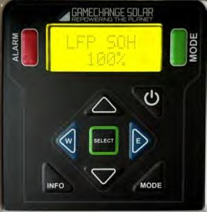


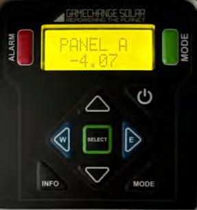
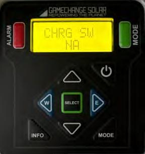
View Peak Actuator Current
To view the peak actuator current readout:
1. Click the Info button in the lower left corner of the control panel to access the information readouts.
2. Use the up and down arrows to find the Actuator Current option and display the actuator current readout.
After 10 seconds, the LCD will revert to the default display.
If the current exceeds 8A, an Overcurrent Alarm will trigger.
View Alarms
If the red Alarm LED to the left of the LCD display is blinking rapidly, the node controller is reporting one or more alarm conditions.
To view the alarms :
1. Click the Info button in the lower left corner of the control panel to access the information readouts.
2. Use the up and down arrows to find the Alarms option and display the Alarms readout.
3. Use the up and down arrow buttons to browse through the alarm readouts.
After 10 seconds, the LCD will revert to the default display.
View Flags
To view the flag conditions currently reported by the node controller:
1. Click the Info button in the lower left corner of the control panel to access the information readouts.
2. Use the up and down arrows to find the Flags option and display the Flags readout.
3. Use the up and down arrow buttons to browse through the flag readouts.
After 10 seconds, the LCD will revert to the default display.
Switch Operating Mode to Regular Tracking
To change the operating mode of the Node Controller to Regular Tracking mode, which is the normal algorithmic solar tracking mode:
1. Click the Mode button in the lower right corner of the control panel to access the operating mode controls.
2. Use the up and down arrows to find the Regular Tracking Mode option and set the operating mode of the Node Controller to Regular Tracking
After 10 seconds, the LCD will revert to the default display.
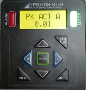


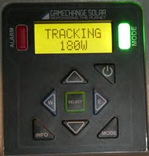
Switch Operating Mode to Hail Stow
To change the operating mode of the Node Controller to Hail Stow, in which the system exits normal algorithmic solar tracking and goes into a static stowed position intended to minimize damage from a hail storm:
1. Click the Mode button in the lower right corner of the control panel to access the operating mode controls.
2. Use the up and down arrows to find the flashing Hail Stow option.
3. Click the Select button to select the option and set the operating mode of the Node Controller to Hail Stow. The table will immediately move to its stowed position. It will move without pausing to cool down.
To take the node controller out of Hail Stow once the storm has passed, set it to the Regular Tracking mode using the instructions on the previous page.
After 10 seconds, the LCD will revert to the default display.
Switch Operating Mode to Snow Stow
To change the operating mode of the Node Controller to Snow Stow, in which the system exits normal algorithmic solar tracking and goes into a static stowed position intended to minimize damage from snow accumulation:
1. Click the Mode button in the lower right corner of the control panel to access the operating mode controls.
2. Use the up and down arrows to find the flashing Snow Stow option.
3. Click the Select button to select the option and set the operating mode of the Node Controller to Snow Stow. The table will immediately move to its stowed position. It will move without pausing to cool down.
To take the node controller out of Snow Stow once the storm has passed, set it to the Regular Tracking mode using the instructions on the previous page.
After 10 seconds, the LCD will revert to the default display.
Switch Operating Mode to Manual Stow
To manually stow the table at one of several preset angles, use the Manual Stow operating mode:
1. Click the Mode button in the lower right corner of the control panel to access the operating mode controls.
2. Use the up and down arrows to find the flashing Manual Stow option.
3. Click the Select button to select the option.
4. Use the up and down arrows to select one of the preset stow angles and click the Select button to select it. The table will immediately move to its stowed position. It will move without pausing to cool down.
To take the node controller out of Manual Stow, set it to the Regular Tracking mode using the instructions on the previous page.
After 10 seconds, the LCD will revert to the default display.
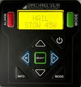
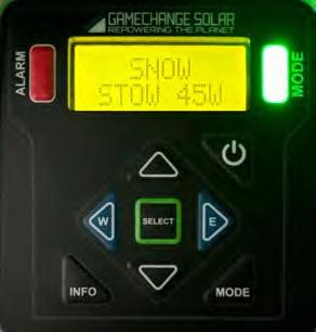
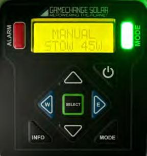
Switch Operating Mode to Stow Flat
To move the table to a horizontal stowed position, use the Stow Flat operating mode
1. Click the Mode button in the lower right corner of the control panel to access the operating mode controls.
2. Use the up and down arrows to find the flashing Stow Flat option.
3. Click the Select button to select the option. The table will immediately move to the horizontal position without pausing to cool down.
After 10 seconds, the LCD will revert to the default display.
Switch Operating Mode to Rescue Mode
If your Node Controller has become disconnected from the mesh network it used to communicate with the Master Controller, you can set it to Rescue Mode so that the mesh network can see the dropped node and reconnect to it:
1. Click the Mode button in the lower right corner of the control panel to access the operating mode controls.
2. Use the up and down arrows to find the flashing Rescue Mode option.
3. Click the Select button to select the option.
The readout will display the various stages of the node rescue operation, ending with either the Node ID of the rescued node, or a Rescue Failed or Rescue Timeout message. During this time, the Node Controller will not respond to front panel button presses.
Once the rescue operation has completed, the Rescue Failed or Rescue Timeout messages can be dismissed by tapping the Select button.
After 10 seconds, the LCD will revert to the default display.

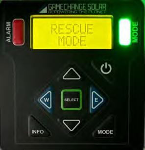
Moving the Table from the Front Panel
The Gen4 Node Controller can move the table directly from the front panel.
NOTE: The front panel will display a PANEL DISCONN message when attempting to move the table with the Charging Panel disconnected. It will display a MOTOR STOP ALM message when attempting to move the table while there is an active Motor Stop alarm, or if one becomes active while the table is moving. Tap the Select button to dismiss these messages.
I Use caution when moving the table from the front panel. Make sure that you will be clear of the table before attempting to change its position. Stay clear of the actuator and do not lower the table onto yourself.
Moving the Table East and West
To move the table a small amount to the East or West:
1. Hold down the E or W button on the front panel for three seconds. The panel will begin to move. The readout will display the Actuator amps and the current table angle.
2. Release the E or W button when you reach the desired angle.
Once you release the E or W button, the LCD will immediately revert back to the Home Screen.
Moving the Table Full East and West
To move the table all the way to the East or West, so that the actuator is fully retracted, or fully extended:
1. Hold down the Mode button.
2. Hold down the E or W button for three seonds. The table will begin to move. The readout will display FULL EAST or FULL WEST
To cancel a Full East or Full West command, tap the power button on the front panel.
Once the table reaches the desired position, the LCD will immediately revert back to the Home Screen.
Moving the Table to a Flat Position
To move the table to a horizontal flat position:
1. Hold down both the E and W buttons for three seconds. The table will begin to move. The readout will display MOVING FLAT.
To cancel a Move Flat command, tap the power button on the front panel.
Once the table reaches the desired position, the LCD will immediately revert back to the Home Screen.
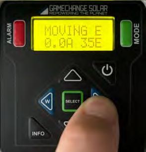
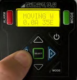
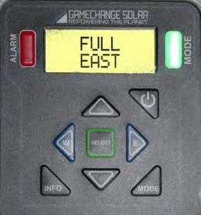

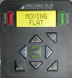
Battery Replacement
The Gen4 Node Controller is built with an access panel that allows you to replace the battery without having to dismount the Node Controller from the Row Tube or disconnect its cabling.
To replace the battery:
1. Power down the Node Controller using the Off/On button on the front control panel.
2. Locate the battery access panel, which is on the rear of the enclosure, opposite from the control panel.
3. Unscrew the retaining screw on the access panel, being careful not to lose the screw or the plastic washer that is on it.
4. Open the battery access panel.
5. Remove the old battery, and disconnect the wires from the battery terminals.
6. Set the old battery aside for recycling.
7. Connect the wires to the battery terminals on the new battery. Connect the red wire to the red positive terminal, and the black and yellow wires to the ground terminal.
8. Place the new battery inside the Node Controller, being careful not to stress or pinch the wiring harness. The new battery should sit flush against the inner wall of the battery compartment.
9. Replace the retaining screw and plastic washer and fasten the access panel closed.
10. Power on the Node Controller using the Off/On button on the front control panel.
11. Recycle the old battery.

Representative Components
Inverters
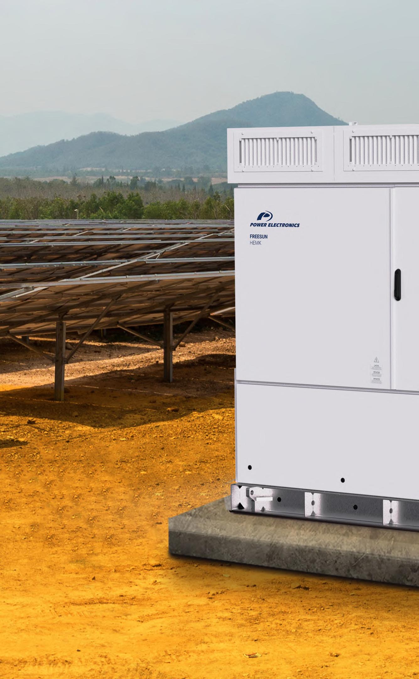
PE genetics
products
We are the heart of photovoltaic plants

We handle everything in-house: from design and manufacture to testing.
+ Storage
25GW
30
50GW years of excellence of annual production capacity of installed AC power + + +
Freesun is the Power Electronics solar inverters range. Power Electronics has become the leading supplier of large-scale plant installations in America, Europe and Oceania and continues to expand worldwide.
SOLAR INVERTERS
Designed for utility-scale solar applications that require the advantages of a central inverter combined with the modular design of string architecture.
Our vertical integration gives us the flexibility and specialization to adapt customer requirements and still provide very short delvery times.
THE HEM
AMERICAN IDOL
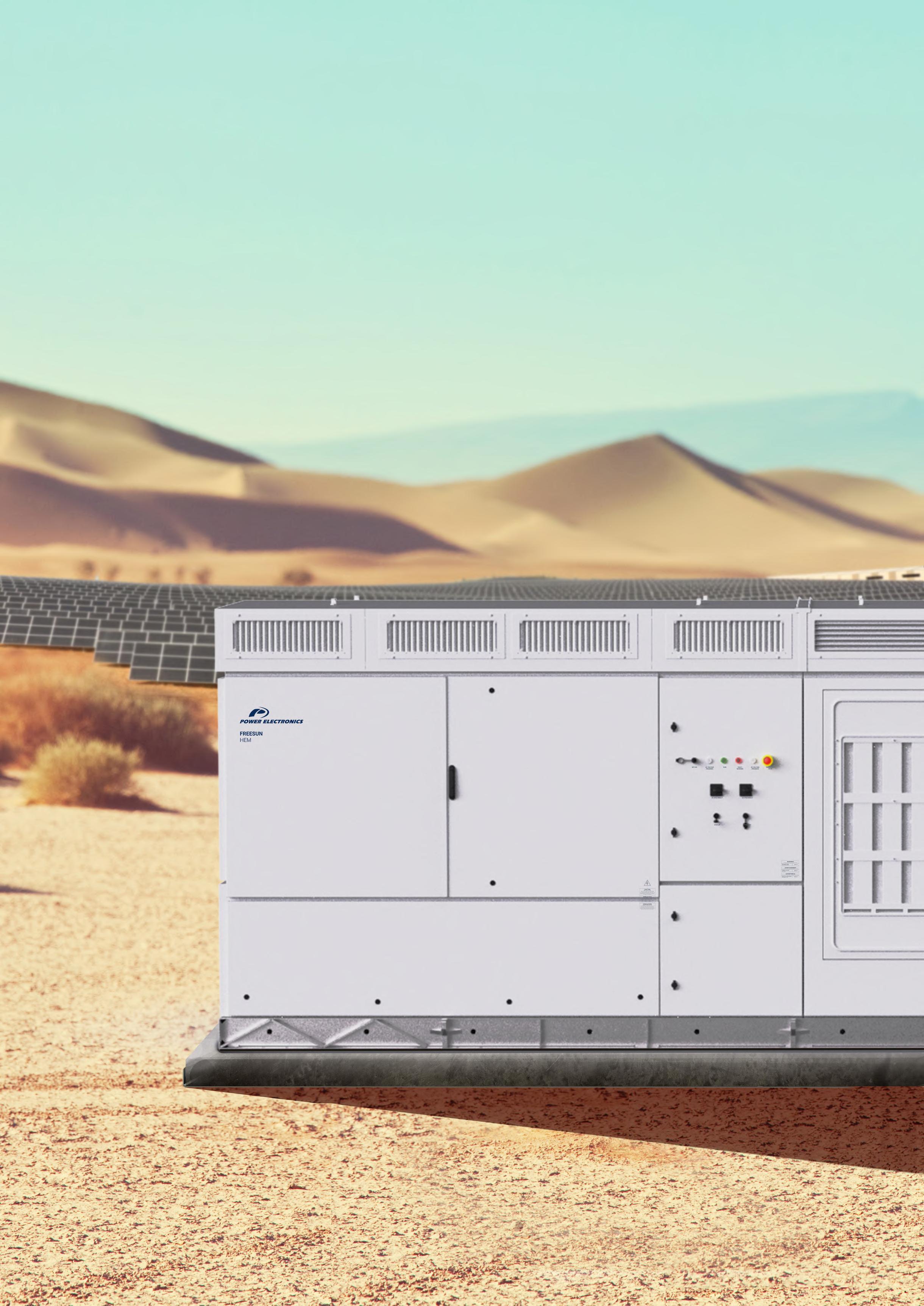
Easy maintenance
The advantages of a central inverter with the modularity of the string inverters.
Designed to be easily replaceable on the field with a safe, reliable, and fast Plug&Play assembly system.
Includes up to 4 FRUs (Field Replaceable Units).
ECON MODE
Remove no-load losses.
Bus Plus
These product has the following characteristics 4
The turn-key solution, simplifies the task of designing the installation, and reduces connection costs. 1 3 2
The Bus Plus feature allows the connection of up to four Freemaq DC/DC converters. It’s the most cost-competitive solution for solar-plus-storage retrofits. Combine solar and storage.
Disconnecting the power station from the grid and taking the medium-voltage transformer out of the circuit, eliminating the continuous energy cost of no-load losses.

Advanced grid support
Capable of operating on any power system, Offering advanced grid support functionalities to comply with the most restrictive grid codes.
iCOOL 3
The most innovative cooling system.
Our own air ventilation system provides a constant flow of clean air inside the equipment, without the need of liquid cooling.

Patented

Active heating
When the unit is not actively exporting power, the inverter can import a small amount of power to keep the inverter internal ambient temperature above -20°C, without using external resistors.
It also can shift to reactive power compensation mode.
Three-level topology
The 3 level IGBT topology reduces stage losses, increases inverter efficiency, and minimizes total harmonic distortion. High efficiency to deliver the lowest cost of energy (LCOE).
STRING INVERTER CABINETS
The ultimate medium-voltage inverter 4.2
DC-coupled storage system from 1200 kW to 4800 kW
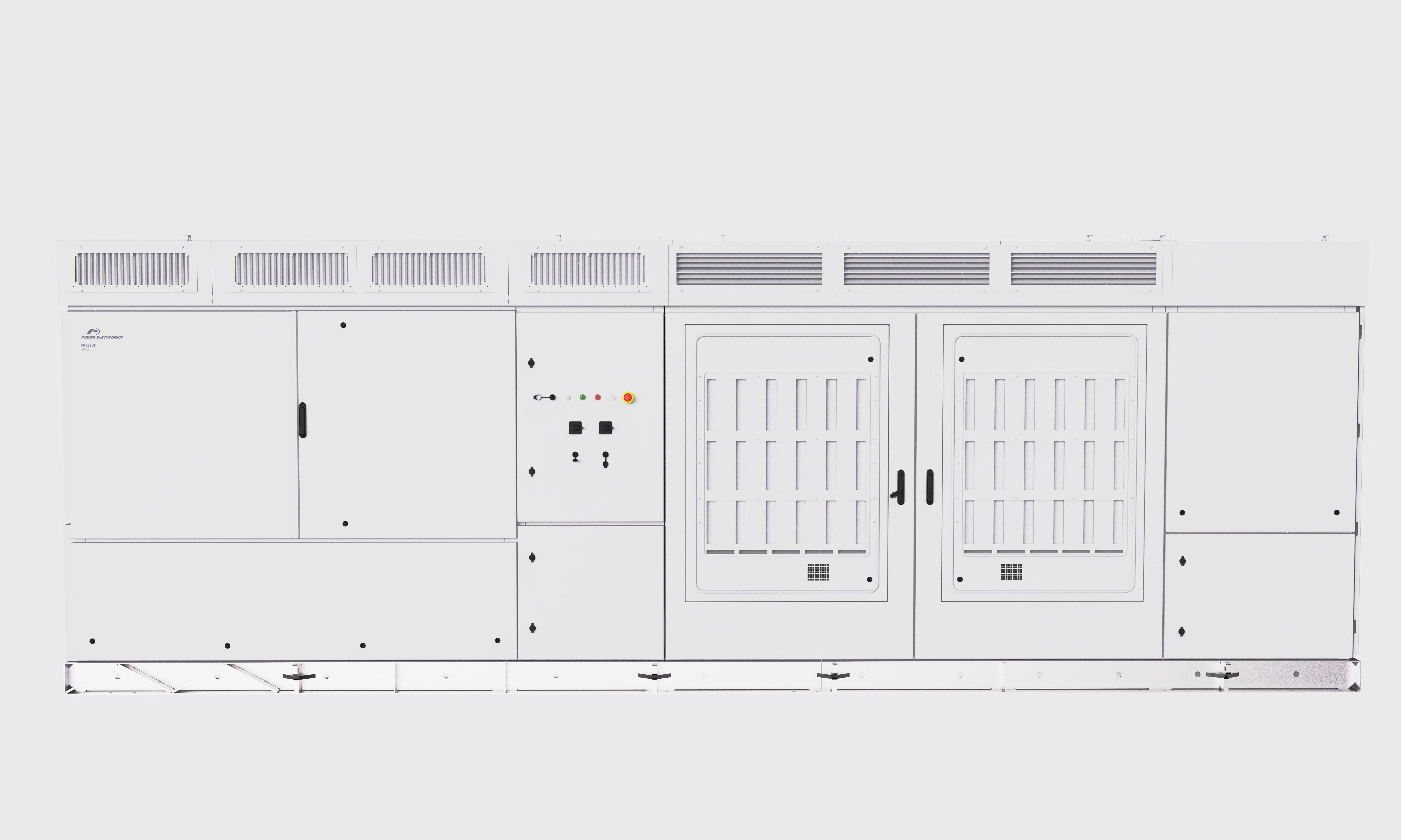
Can reach up to a nominal power of
INPUT
AC Output Power (kVA/kW)
@40°C[1] 4200
AC Output Power (kVA/kW) @50°C[1] 3900
Operating Grid Voltage (kV)[2]
EFFICIENCY
CABINET
ENVIROMENT
REFERENCES
FS4105M
AC Output Power (kVA/kW)@40°C[1] 4105
AC Output Power (kVA/kW)@50°C[1] 3810
Operating Grid Voltage (kV)[2]
OUTPUT
34.5kV ±10%
Operating Grid Frequency (Hz) 60Hz
Current Harmonic Distortion (THDi) < 3% per IEEE519
Power Factor (cosine phi)[3] 0.5 leading … 0.5 lagging adjustable / Reactive power injec- tion at night
DC Voltage Range[4] 934V - 1500V
Maximum DC Voltage 1500V
Number of Inputs Up to 40
Max. DC Continuous Current (A)[5] 4590
Max. DC Short Circuit Current (A)[5] 6940
Number of MPPt (floating systems) 1, optionally 2 or 4
Number of Freemaq DC/DC[5] Up to 2 (Bus Plus Basic) or 4 (Bus Plus Advanced)
Efficiency (Max) (η) 97.8% including MV transformer
Euroeta (η) 97.51% including MV transformer
Dimensions [WxDxH] (ft) 21.3 x 6.5 x 7.2
Dimensions [WxDxH] (m) 6.5 x 2.0 x 2.2
Weight (lbs) 30865
Weight (kg) 14000
Type of Ventilation Forced air cooling
Degree of Protection NEMA 3R
Permissible Ambient Temperature -35°C to +60°C, >50°C / Active power derating
Relative Humidity 4% to 100% non-condensing
Max. Altitude (above sea level)[6] 2000m
CONTROL INTERFACE Communication Protocol Modbus TCP Power Plant Controller Optional
Keyed ON/OFF Switch Standard
Ground Fault Protection GFDI and isolation monitoring device
Humidity Control Active heating
INPUT
34.5kV ±10%
Operating Grid Frequency (Hz) 60Hz
Current Harmonic Distortion (THDi) < 3% per IEEE519
Power Factor (cosine phi)[3] 0.5 leading … 0.5 lagging adjustable / Reactive power injection at night
DC Voltage Range[4] 913V - 1500V
Maximum DC Voltage 1500V
Number of Inputs Up to 40
Max. DC Continuous Current (A)[5] 4590
Max. DC Short Circuit Current (A)[5] 6940
Number of MPPt (floating systems) 1, optionally 2 or 4
Number of Freemaq DC/DC[5] Up to 2 (Bus Plus Basic) or 4 (Bus Plus Advanced)
EFFICIENCY
CABINET
ENVIROMENT
CONTROL INTERFACE
PROTECTIONS
PROTECTIONS
General AC Protection & Disconn. MV switchgear (20 or 25 kA)
General DC Protection & Disconn. Fuses, DC switch-disconnectors
Overvoltage Protection Type 2 protection for AC and DC (optionally, Type 1+2 for DC side)
CERTIFICATIONS & STANDARDS Safety UL 1741 / CSA 22.2 No.107.1-16
Installation NEC 2020
Utility Interconnect IEEE 1547:2018 / UL 1741 SB
[2] Consult Power Electronics for other configurations.
[3] Consult P-Q charts available: Q(kVAr)=√(S(kVA)2-P(kW)2).
CERTIFICATIONS & STANDARDS
Efficiency (Max) (η) 97.76% including MV transformer Euroeta (η)
including MV transformer
Dimensions [WxDxH] (ft) 21.3 x 6.5 x 7.2
Dimensions [WxDxH] (m) 6.5 x 2.0 x 2.2
Weight (lbs) 30865
Weight (kg) 14000
Type of Ventilation Forced air cooling
Degree of Protection NEMA 3R
Permissible Ambient Temperature -35°C to +60°C, >50°C / Active power derating
Relative Humidity 4% to 100% non-condensing
Max. Altitude (above sea level)[6] 2000m
Communication Protocol Modbus TCP
Power Plant Controller Optional
Keyed ON/OFF Switch Standard
Ground Fault Protection GFDI and isolation monitoring device
Humidity Control Active heating
General AC Protection & Disconn. MV switchgear (20 or 25 kA)
General DC Protection & Disconn. Fuses, DC switch-disconnectors
Overvoltage Protection Type 2 protection for AC and DC (optionally, Type 1+2 for DC side)
Interconnect
REFERENCES FS4010M
AC Output Power (kVA/kW)@40°C[1] 4010
AC Output Power (kVA/kW)@50°C[1] 3720
Operating Grid Voltage (kV)[2]
OUTPUT
34.5kV ±10%
Operating Grid Frequency (Hz) 60Hz
Current Harmonic Distortion (THDi) < 3% per IEEE519
Power Factor (cosine phi)[3] 0.5 leading … 0.5 lagging adjustable / Reactive power injec- tion at night
DC Voltage Range[4] 891V - 1500V
Maximum DC Voltage 1500V
Number of Inputs Up to 40
INPUT
Max. DC Continuous Current (A)[5] 4590
Max. DC Short Circuit Current (A)[5] 6940
Number of MPPt (floating systems) 1, optionally 2 or 4
Number of Freemaq DC/DC[5] Up to 2 (Bus Plus Basic) or 4 (Bus Plus Advanced)
EFFICIENCY Efficiency (Max) (η)
CABINET
ENVIROMENT
CONTROL INTERFACE
PROTECTIONS
97.75% including MV transformer
Euroeta (η) 97.48% including MV transformer
Dimensions [WxDxH] (ft) 21.3 x 6.5 x 7.2
Dimensions [WxDxH] (m) 6.5 x 2.0 x 2.2
Weight (lbs) 30865
Weight (kg) 14000
Type of Ventilation Forced air cooling
Degree of Protection NEMA 3R
Permissible Ambient Temperature -35°C to +60°C, >50°C / Active power derating
Relative Humidity 4% to 100% non-condensing
Max. Altitude (above sea level)[6] 2000m
Communication Protocol Modbus TCP Power Plant Controller Optional
Keyed ON/OFF Switch Standard
Ground Fault Protection GFDI and isolation monitoring device
Humidity Control Active heating
General AC Protection & Disconn. MV switchgear (20 or 25 kA)
General DC Protection & Disconn. Fuses, DC switch-disconnectors
Overvoltage Protection Type 2 protection for AC and DC (optionally, Type 1+2 for DC side)
Safety
CERTIFICATIONS & STANDARDS
UL 1741 / CSA 22.2 No.107.1-16
Installation NEC 2020
Utility Interconnect IEEE 1547:2018 / UL 1741 SB
[1] Values at 1.00·Vac nom and cosφ=1. Consult Power Electronics for derating curves.
[2] Consult Power Electronics for other configurations.
[3] Consult P-Q charts available: Q(kVAr)=√(S(kVA)2-P(kW)2). [4] Consult
HARDWARE AND INSTALLATION MANUAL


Hardware and Installation Manual
Edition: September 2022
ABOUT THIS DOCUMENT
PURPOSE
This manual contains important instructions for the installation, configuration and use of Power Electronics Freesun HEM GEN3.
TARGET AUDIENCE
This manual is intended for qualified customers who will install, configure and operate Power Electronics Freesun HEM GEN3.
Only trained electricians approved by Power Electronics may install and commission the equipment. The instructions assume that the installer is familiar with electrical installation rules and regulations.
REFERENCE MANUALS
The following reference documents are available for the Freesun HEM GEN3 inverters:
Hardware and Installation Manual.
Maintenance Manual.
Software and Programming Manual.
POWER ELECTRONICS CONTACT INFORMATION
Power Electronics USA Inc. 1510 N. Hobson Street, Gilbert, Phoenix AZ 85233
UNITED STATES OF AMERICA
US Sales: 602-354-4890 / (480) 519-5977
Power Electronics España, S.L. Polígono Industrial Carrases RondadelCampd’Aviaciónº4 46160, Llíria (Valencia) SPAIN
Telephone: (+34) 96 136 65 57 Website: www.power-electronics.com
DATE (DD/MM/YYYY)
REVISIONS CONTROL
REVISION DESCRIPTION
14 / 04 / 2021 A First edition.
11 / 05 / 2021 B Misprints correction.
23 / 11 / 2021 C
17 / 05 / 2022 D
Acronyms. Introduction. Technical characteristics. Handling, transportation and installation. Wiring, access and connection. LEDs and controls. Operation. Misprints correction.
Acronyms. Introduction. Technicalcharacteristics. Dimensions and weight. Handling, transportation and installation. Wiring, access and connection. Protections. Commissioning. Misprints correction.
06 / 09 / 2022 E Important safety instructions. Torque and screw sizing. Technical characteristics. Handling, transportation and installation. Wiring, access and connection. Operation. Misprints correction.
The equipment and technical documentation are periodically updated. Power Electronics reserves the right to modify all or part of the contents of this manual without previous notice. To consult the most updated information of this product, you may access our website www.power-electronics.com, where the latest version of this manual can be downloaded. The reproduction or distribution of the present manual is strictly forbidden, unless express authorization from Power Electronics.
ACRONYMS
ThetermscommonlyusedinthedocumentationofPowerElectronics’productsarelistedinthetable below.
Please notice this is a general series of terms and it encompasses all our product divisions (industrial, solar, storage, and electric mobility), thus, some of the following expressions may not apply to this particular manual.
ACRONYM MEANING
AASS Auxiliary Services
AC Alternating Current
AI Analogue Input
AO Analogue Output
BESS Battery Energy Storage System
BMS Battery Manager Solution
CCID Charge circuit interrupting device
CCL Charge Current Limit.
CCS
Combined charging system – charging and communications protocol following the standard IEC 61851-23 Annex CC
CHAdeMO Charging and communications protocol following the standard IEC 61851-23 Annex AA
CPU Central Processing Unit
DC Direct Current
DCL Discharge Current Limit
DI Digital Input
DSP Digital Signal Processor
DO Digital Output
EMS Energy Management System
EV Electric Vehicle
FPGA Programmable device (Field-Programmable Gate Array)
FRU Field Replaceable Unit
GFDI Ground Fault Detector Interrupter
GPRS General Packet Radio Services, a data transmission system
HVAC Heating, Ventilation, and Air Conditioning
IGBT Insulated Gate Bipolar Transistor
IMI Insulation monitoring device
IT Grid system where the power supply is kept isolated and the electrical equipment system is grounded.
LOTO Lock Out – Tag Out
MCB Miniature Circuit Breaker
MCCB Moulded Case Circuit Breaker
MPCS Multi Power Conversion System
MID Measuring Instrument Directive
MV Medium Voltage. This term is used to refer to high voltage in general
PE Ground connection
PI Proportional and Integral
POI Point Of Interconnection
PPE Personal Protection Equipment
ACRONYM MEANING
PV Photovoltaic energy
RCD Residual Current Device
RCM Residual Current Monitor
RFID Radio Frequency Identification
SOC State Of Charge – referred to battery
SOH State Of Health – referred to battery. It compares the actual state of the battery to its initial conditions. It is measured in percentage
STO Safe Torque Off
TN Grid system where the power supply is grounded, and the electrical equipment system is brought to the same ground through the neutral connector.
TT Grid system where both the power supply and the electrical devices are connected to the ground via separate connections
UPS Uninterruptible Power Supply
VSD / VFD Variable Speed Drive, Variable Frequency Drive. Both terms are used
SAFETY SYMBOLS
Always follow safety instructions to prevent accidents and potential hazards from occurring. In this manual, safety messages are classified as follows:
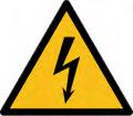
WARNING

CAUTION

NOTICE
Identifies potentially hazardous situations where dangerous voltage may be present which if not avoided could result in minor personal injury, serious injury or death
Be extremely careful and follow the instructions to avoid the risk of electrical shocks.
Identifies potentially hazardous situations which if not avoided could result in product damage or minor or moderate personal injury.
Read the message and follow the instructions carefully.
Identifies important measures to take in order to prevent damage equipment and warranty lost, as well as encouraging good use and environmental practices.
Other symbols used in this manual for safety messages are the following:



Hot surface. Be careful and follow the instructions to avoid burns and personal injuries.
Risk of fire. Be careful and follow the instructions to prevent causing an unintentional fire.
Caution, risk of electric shock. Energy storage timed discharge. Wait for the indicated time to avoid electrical hazards.
Caution, risk of hearing damage. Wear hearing protection.
IMPORTANT SAFETY INSTRUCTIONS
SAVE THIS INSTRUCTIONS
This manual contains important instructions for HEM GEN3 that shall be followed during installation and maintenance of the inverter.
Read carefully all documentation before manipulating the inverter, also mentioned as the equipment, and pay special attention to safety recommendations to maximize the performance of this product and to ensure its safe use and installation.
It is the installer’s responsibility to follow the instructions provided on this manual, to follow good electrical practices and to identify all mentioned warnings and recommendations before starting up and operating the equipment.

WARNING
If the instructions on this manual are not followed, the HEM inverter system may present a SHOCK HAZARD. Read and retain the Hardware and Installation Manual for future reference. Before installing the equipment, read all instructions and cautionary markings. Failure to follow the safety instructions could result in a severe shock or even death. Exercise extreme caution always to prevent possible accidents.
Ensure the equipment is completely disconnected from the power supply and connected to ground before manipulating it or performing any maintenance tasks. Otherwise, electric shock hazard exists.
To prevent electrical hazards, disconnect input supply, connect the equipment to ground, remove all control voltages before carrying out any task and ensure busbars are completely discharged. Warning and safety labels must be properly placed in terminals, enclosures and control panels according to local normative in force.
In addition to the recommendations on this manual, local and site-specific safety procedures must be taken into account. Also, national and local electrical codes must be followed in order to avoid personal injuries and/or equipment damage.
Failure to comply with safety instructions and electrical codes may void the warranty.
When working in electrical installations always remember to apply the FIVE GOLDEN RULES:
1. Visible cutout of all sources in voltage.
2. Mechanical locking of all cutting elements.
3. Check the absence of voltage using appropriate tools for the installation voltage (e.g. pole for medium voltage).
4. Ground and short-circuit all possible voltage sources.
5. Define and mark the work area.

NOTICE
Consult LOTO procedure in the Maintenance Manual.

WARNING
Once LOTO procedures are complete, ensure AC are also cut off before making any actions on the HEM. There could be hazardous voltages present in the busbars and you may get an electric shock.
Do not connect any supply to the equipment while the doors are open. Otherwise, you could get an electric shock.
Do not apply power to a damaged equipment or to an equipment with missing parts even if the installation is complete. Otherwise, you could get an electric shock.
Keep all doors closed during equipment operation. Otherwise, you could get an electric shock.
Before opening any doors or covers, ensure to follow the isolation guidelines and all safety instructions. Otherwise, you could get an electric shock.
Always operate switches with dry hands and use personal protective equipment (PPE). Otherwise, you could get an electric shock.
Any tasks performed in the equipment must be carried out with, at least, two operators. The equipment should never be operated by a single operator.
Do not use cables with damaged insulation. Do not subject the cables to abrasions, excessive stress, heavy loads or pinching. Otherwise, you could get an electric shock.
Ensure compliance of all safety regulations for medium voltage operations that are in force at the place where the equipment is installed. Otherwise, you could get an electric shock.
In case the equipment stops due to a power loss, do not perform any works on it. Automatic restart function might be enabled, and you could get an electric shock.
Always follow proper lockout/tagout procedures. For further information, refer to the Maintenance Manual.


4 min
The device contains capacitors on the AC and DC sides. The discharge time of the capacitors is 4 minutes. Wait until the capacitors have been discharged before carrying out any maintenance task.
Work at heights shall be carried out under the appropriate safety conditions and equipment and always in accordance with the regulations of the country where the operation is carried out.

WARNING
ISOLATION GUIDELINES
To guarantee the safety of the personnel who will work on the inverter, it is essential to open the input circuit breaker and ground the MV switchgear that provides supply to the equipment. Besides this, the customer must remove voltage from the MV facility network switchgear and discharge it to ground by keeping it in ground position while the equipment is open (unless a task specific Health and Safety study is completed, and task specific procedure is available)
Additionally, it is necessary to fully disconnect the DC supply from the photovoltaic field to the equipment, unless a task specific Health and Safety study is completed, and task specific procedure is available. In this case, please notice the DCcabinet cannot beopened as there is voltage present from the photovoltaic field.
To carry out any maintenance or activity inside the inverter, the user must verify there is no voltage presence in the equipment, as well as to carry out the LOTO procedure as stated in the Maintenance Manual. Always apply the five golden rules to ensure there are no hazardous voltages.
These maneuvers are out of the scope of Power Electronics’ staff Customer will be responsible to guarantee the safety or Power Electronics personnel who intervenes in the equipment.

WARNING
GROUND CONNECTION
Electric shock prevention:
The inverter chassis must be properly grounded to prevent a possible electric shock if a leakage current flows through the enclosure. Disconnect all the voltage supplies before proceeding with maintenance operations within the equipment. The equipment contains capacitors which may have a hazardous voltage even when the input voltage is disconnected. Make sure the equipment is discharged before performing any operation.
Only connect the earth grounding to the equipment’s earth plate Do not use the case or the chassis screw for grounding.
The earth protection cable must be connected first and disconnected last.
The HEM inverter must be connected to ground by using the ground busbar located in the medium voltage switchgear.
AC output cables are medium voltage cables. As shown in the figure below, they are coaxial cables, each one including earth. To carry out a correct connection, it is necessary to bond the earth of each phase and connect it to the ground busbar of the equipment (located in the MV voltage switchgear).
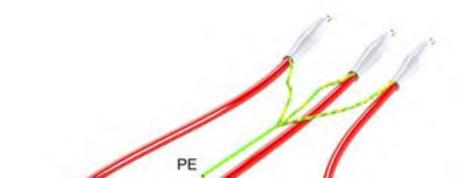

REQUIRED PERSONAL PROTECTION EQUIPMENT
(PPE from now on)
PPE is required according to standards for repairing and maintaining Freesun inverters. Always follow the site operative instructions to fulfil the compliance of national or local normative.
In case of actions with voltage presence, it is compulsory to use an Arc Flash Safety Kit (gloves, clothes and face shield).
A detailed example of PPE used will be shown below. Customer must specify in his safety instructions (risk assessment and method statements) which ones are the PPE and when and how they should be used according to his electric arc studies, the characteristics of site, equipment, installation and country.
Power Electronics accepts no responsibility or liability for any damages resulting from inappropriate use of the equipment or failure to comply national or local normative.
The following table includes just an example of commonly used PPE description. Always follow local regulations / NFPA 70Estandards about Safety and Health.
ITEM
Safety glasses
Electric gloves
Safety footwear
Insulation carpet
Safety kit arc flash
Lock Out / Tag Out elements set
HI-VIS vest
MV stool
Rescue pole


DESCRIPTION
Eye protection according to EN 166.
Gloves with mechanical, dielectric and against arc flash.
Class according to voltage.
ASTM D120 specifications and NFPA 70E standards.
S3 class complying with BS EN ISO 20345.
Isolation carpet according to IEC 61111
Class according to voltage.
Arc flash personal protective equipment kit (including arc flash protective face shield & hard hat), fire resistant 100 cal/cm2
Padlock and auxiliary elements set to lock out danger equipment.
Fr VIS vest 9 cal/cm2
Medium Voltage insulation stool.
Insulated body rescue pole.


Additional PPE for commissioning and maintenance tasks



Safety clothes according to NFPA-70E and safety labels
The following table shows the protection class type, depending on the working voltage. ELECTRICAL INSULATED GLOVES
ELECTRICAL SAFETY MATTING

CAUTION
Install the equipment on a solid and levelled surface. Follow the recommendations on how to build the foundation. Otherwise, there is a risk of malfunction and even permanent damage.


Disconnect the input power in case the equipment gets damaged. Otherwise, it could result in a secondary accident or a fire.
Do not allow lint, paper, wood chips, dust, metallic chips or other foreign matter into the equipment. Otherwise, a fire or an accident could occur.
After the input power is applied or removed, the equipment will remain hot for a few minutes. Touching internal hot parts could result in skin burns.

NOTICE
RECEPTION
Equipment is supplied after passing strict operational tests and it is carefully packed for shipment. In the event of damage to the unit during transportation, notify the transport agency and Power Electronics (International +34 96 136 65 57, US +1-415-874-3668) or your nearest agent, within 24hrs from receipt of the goods.
RECYCLING
Equipment packaging must be recycled. Separate all different materials (plastic, paper, cardboard, wood ) and place them in the corresponding containers. Ensure waste collection is properly managed with a NonHazardous Waste Agent.

To guarantee health and natural environmental sources protection, the European Union has adopted the WEEE directive concerning discarded electric andelectronic equipment (SEEA).
Waste of electrical and electronic equipment (WEEE) must be collected selectively for proper environmental management.
Our products contain electronic cards, capacitors and other electronic devices that should be separated when they are no longer functional. These WEEEs should be managed accordingly with a Hazardous Waste Agent.
Power Electronics promotes good environmental practices and recommends that all its products sold outside of the European Union, once they reach the end of their life, are separated and the WEEE managed according to the particular country applicable legislation (especially electronic cards, capacitors and other electronic devices).
If you have any questions about the electric and electronic equipment waste, please contact Power Electronics.
TORQUE AND SCREW SIZING
The following table shows the recommended tightening torque for both mechanical and electrical connections, applicable to all cabins [1 2]:
[a] For other qualities, follow the screw’s manufacturer guidelines

CAUTION
For all screwing that hold a particular component such as a bus, contactor, etc. it will be necessary to apply the tightening torque indicated by the manufacturer of the same component.
Screwing should be tightened correctly only when necessary, i.e. when the factory marks are not in place. For small screws that do not have marks, the good electrical praxis will determine if it is loose.
1 Power Electronics recommends the use of Zinc Steel quality 8.8 bolts for internal connections in general, DC and earth connections included.
2 Power Electronics recommends the use of A2-70 stainless bolts for external connections in general, AC connections included.
1.INTRODUCTION
The Power Electronics HEM medium voltage inverter is designed for utility scale solar applications that require the advantages of a central inverter solution but also the modularity of a string architecture. The HEM can reach up to a nominal power of 4.2 MVA and offers a wide MPPT window. It also has the added advantage of having an integrated medium voltage transformer and a switchgear.
The Bus Plus feature allows the connection of the Freemaq DC/DC converters. It is the most cost competitive solution for solar-plus-storage retrofits.
Its architecture, composed of four field replaceable units (FRU), is designed to provide the highest availability and optimize yield production.
Its use in Utility Scale PV plants provides considerable savings in CAPEX (Capital Expenditure), since having an integrated MV transformer and switchgear reduces the need of additional connections between the LV and MV sides.
Thanks to the Power Electronics cooling system, the HEM is able to provide NEMA 3R degree of protection with an air-cooling system, and as a result, reducing OPEX (Operating Expenditure) costs. This product has been designed to be the lowest LCOE solution in the market for solar applications.
Modularity
The HEM combines the advantages of a central inverter with the modularity of the string inverters. Its power modules are designed to be easily replaceable on the field without the need of advanced technical service personnel, providing a safe, reliable and fast Plug&Play assembly system. Following the modular philosophy of the Freesun series, the HEM is composed of 4 FRUs (field replaceable units).

Cabinets distribution
The following image shows the cabinets distribution in HEM inverter1

Cabinets distribution
Number in figure Cabinet
1, 2, 14, 19 MV Switchgear cabinet
15 – 17 DC cabinet 2
Detail
1: Access door to MV switchgear.
2, 19: Access door to MV AC cables installation.
14: Econ Mode (optional)
15, 16: DC cabinet access doors. DC current measurement and protections: input fuses, insulation monitor, DC surge arrester and DC switch disconnectors. DC manual disconnectors are optional.
17: Access covers for DC wiring connection.
3 Inverter cabinet 3: Access door to removable power stages (FRUs).
4 AASS transformer 4: Auxiliary services (AASS) transformer.
5 Protections and measurements Ventilation protections. MV measurements. 6, 7 Ventilation grids 6: Air inlets for the cooling system.
7: Air outlets for the cooling system.
8,9 Cooling cabinet
10, 11, 12 LC filter cabinet
13 Main control cabinet
8: Air inlets for the cyclone system and dust particles outlet. Access door for the cyclone filter and impulsion fan. MV transformer access cover.
9: Dust particles outlet.
10: C filter access cover, RFI board, crowbar 11: AC surge arrester, AASS fuses.
12: Main inductance access cover.
13: Controls for user local control, central control board and communication devices (Ethernet switch).
18 User cabinets 18: User cabinet1
1 Configuration will vary depending on the customizable options chosen by the customer.
2 Varies according to the number of DC inputs.
2.TECHNICAL CHARACTERISTICS
REFERENCES
AC
FS4200M
AC Output Power (kVA/kW) @40°C[1] 4200
AC Output Power (kVA/kW) @50°C[1] 3900
FS4201M
Operating Grid Voltage (kV)[2] 34.5kV ±10% 13.8kV ±10%
Operating Grid Frequency (Hz) 60Hz
Current Harmonic Distortion (THDi) < 3% per IEEE519
Power Factor (cosine phi)[3]
DC
EFFICIENCY
0.5 leading 0.5 lagging adjustable / Reactive power injection at night
DC Voltage Range[4] 934V- 1500V
Maximum DC Voltage 1500V
Number of Inputs Up to 40
Max. DC Continuous Current (A)[5] 4590
Max. DC Short Circuit Current (A)[5] 6940
Number of Freemaq DC/DC[5] Up to 4
Efficiency (Max) (η) (preliminary)
Euroeta (η) (preliminary)
CABINET Dimensions [WxDxH] (ft)
Dimensions [WxDxH] (m)
97.80% including MV transformer
97.51% including MV transformer
21.3 x 6.6 x
Weight (lbs) 30865
Weight (kg) 14000
Type of Ventilation Forced air cooling
ENVIROMENT Degree of Protection NEMA 3R / IP55 for IEC
Permissible Ambient Temperature[6] -25°C to +60°C, >50°C Active power derating
Relative Humidity 4% to 100% non-condensing
Max. Altitude (above sea level)[7] 2000m
CONTROL
INTERFACE Communication Protocol
PROTECTIONS
Modbus TCP
Power Plant Controller Optional
Keyed ON/OFF Switch Standard
Ground Fault Protection GFDI and isolation monitoring device
Humidity Control Active heating
General AC Protection & Disconn. MV switchgear (20 or 25 kA) / (2L+V) for IEC
General DC Protection & Disconn. Fuses, DC switch-disconnectors
Overvoltage Protection
CERTIFICATIONS & STANDARDS
Notes:
Type 2 protection for AC and DC (optionally, Type 1+2 for DC side)
Safety UL1741, CSA 22.2 No.107.1-16 / IEC 62477-2
Installation NEC 2020
Utility Interconnect IEEE 1547:2018 / UL 1741 SB
[1] Values at 1 00•Vac nom and cos Ф= 1 Consult Power Electronics for derating curves.
[2] Consult Power Electronics for other configurations.
[3] Consult P-Q charts available: Q(kVAr)=√(S(kVA)2-P(kW)2).
[4] Consult Power Electronics for derating curves.
[5] Consult Power Electronics for Freemaq DC/DC connection configurations.
[6] Optional available for temperatures down to -35ºC.
[7] Consult Power Electronics for altitudes above 1000 m.
REFERENCES
AC
AC Output Power (kVA/kW) @40°C[1] 4105
AC Output Power (kVA/kW) @50°C[1] 3810
Operating Grid Voltage (kV)[2] 34.5kV ±10% 13.8kV ±10%
Operating Grid Frequency (Hz) 60Hz
Current Harmonic Distortion (THDi) < 3% per IEEE519
Power Factor (cosine phi)[3]
DC
EFFICIENCY
CABINET
0.5 leading 0.5 lagging adjustable / Reactive power injection at night
DC Voltage Range[4] 913V - 1500V
Maximum DC Voltage 1500V
Number of Inputs[2] Up to 40
Max. DC Continuous Current (A)[5] 4590
Max. DC Short Circuit Current (A)[5] 6940
Number of Freemaq DC/DC[5] Up to 4
Efficiency (Max) (η) (preliminary)
Euroeta (η) (preliminary)
Dimensions [WxDxH] (ft)
ENVIROMENT
97.76% including MV transformer
97.50% including MV transformer
21.3 x 6.6 x 7.2
Dimensions [WxDxH] (m) 6.5 x 2.0 x 2.2
Weight (lbs) 30865
Weight (kg) 14000
Type of Ventilation Forced air cooling
Degree of Protection NEMA 3R / IP55 for IEC
Permissible Ambient Temperature[6] -25°C to +60°C / >50°C Active power derating
Relative Humidity 4% to 100% non-condensing
Max. Altitude (above sea level)[7] 2000m
CONTROL INTERFACE Communication Protocol
PROTECTIONS
Modbus TCP
Power Plant Controller Optional
Keyed ON/OFF Switch Standard
Ground Fault Protection
GFDI and Isolation monitoring device
Humidity Control Active heating
General AC Protection & Disconn. MV Switchgear (20 or 25 kA) / (2L+V) for IEC
General DC Protection & Disconn. Fuses, DC switch-disconnectors
Overvoltage Protection Type 2 protection for AC and DC (optionally, Type 1+2 for DC side)
CERTIFICATIONS & Safety UL1741, CSA 22.2 No.107.1-16 / IEC 62477-2
STANDARDS Compliance NEC 2020
Utility Interconnect IEEE 1547:2018 / UL 1741 SB
Notes:
[1] Values at 1 00•Vac nom and cos Ф= 1 Consult Power Electronics for derating curves
[2] Consult Power Electronics for other configurations.
[3] Consult P-Q charts available: Q(kVAr)=√(S(kVA)2-P(kW)2).
[4] Consult Power Electronics for derating curves.
[5] Consult Power Electronics for Freemaq DC/DC connection configurations.
[6] Optional available for temperatures down to -35ºC.
[7] Consult Power Electronics for altitudes above 1000m.
REFERENCES FS4010M FS4011M
AC
AC Output Power (kVA/kW) @40°C[1] 4010
AC Output Power (kVA/kW) @50°C[1] 3720
Operating Grid Voltage (VAC)[2] 34.5kV ±10% 13.8kV ±10%
Operating Grid Frequency (Hz) 60Hz
Current Harmonic Distortion (THDi) < 3% per IEEE519
Power Factor (cosine phi)[3]
DC
EFFICIENCY
CABINET
0.5 leading 0.5 lagging adjustable / Reactive power injection at night
DC Voltage Range[4] 891V- 1500V
Maximum DC Voltage 1500V
Number of Inputs Up to 40
Max. DC Continuous Current (A)[5] 4590
Max. DC
Circuit Current (A)[5] 6940
Number of Freemaq DC/DC[5] Up to 4
Efficiency (Max) (η) (preliminary)
Euroeta (η) (preliminary)
Dimensions [WxDxH] (ft)
ENVIROMENT
including MV transformer
including MV transformer
21.3 x 6.6 x 7.2
Dimensions [WxDxH] (m) 6.5 x 2.0 x 2.2
Weight (lbs) 30865
Weight (kg) 14000
Type of Ventilation Forced air cooling
Degree of Protection NEMA 3R / IP55 for IEC
Permissible Ambient Temperature[6] -25°C to +60°C / >50°C Active Power derating
Relative Humidity 4% to 100% non-condensing
Max. Altitude (above sea level)[6] 2000m
CONTROL INTERFACE Communication Protocol
PROTECTIONS
Modbus TCP
Power Plant Controller Optional
Keyed ON/OFF Switch Standard
Ground Fault Protection
GFDI and Isolation monitoring device
Humidity Control Active heating
General AC Protection & Disconn. MV switchgear (20 or 25 kA) / (2L+V) for IEC
General DC Protection & Disconn. Fuses, DC switch-disconnectors
Overvoltage Protection Type 2 protection for AC and DC (optionally, Type 1+2 for DC side)
CERTIFICATIONS & Safety UL1741, CSA 22.2 No.107.1-16 / IEC 62477-2
STANDARDS Compliance NEC 2020
Utility Interconnect IEEE 1547:2018 / UL 1741 SB
Notes:
[1] Values at 1 00•Vac nom and cos Ф= 1 Consult Power Electronics for derating curves
[2] Consult Power Electronics for other configurations.
[3] Consult P-Q charts available: Q(kVAr)=√(S(kVA)2-P(kW)2).
[4] Consult Power Electronics for derating curves.
[5] Consult Power Electronics for Freemaq DC/DC connection configurations.
[6] Optional available for temperatures down to -35ºC.
[6] Consult Power Electronics for altitudes above 1000 m.
3.DIMENSIONS AND WEIGHT
Dimensions and center of gravity
The dimensions and center of gravity of the HEM GEN3 inverter are shown below:

Weight
Total weight is approximately 14 t (30865 lb).
4.HANDLING, TRANSPORTATION AND INSTALLATION

CAUTION
Read carefully the following transportation and installation instructions. Failure to follow transportation and installation instructions could result in damage to the equipment or injury to people.
Delivery and storage
Power Electronics’ inverters are carefully tested and packed for shipment In the event of damage to the unit during transportation, notify the transport agency and Power Electronics (International +34 96 136 65 57, US +1-415-874-3668), or your nearest agent, within 24 hours from receiving the goods.
Make sure the model and serial number of the product match the information on the delivery packing list.
The inverter should be stored in a location that is protected from direct sun and moisture excess. The storage temperature rating for the inverter is -35 ºC to +60 ºC (-31 ºF to +140 ºF)
Standard storage
If an inverter is stored for a short period of time before its connection, the following rules will keep the unit safe until it is ready for installation:
The equipment should be stored in a location that is protected from moisture (inside and outside the equipment).
Avoid floodable grounds. No part of the equipment should ever be submerged under water.
Temperature in the storage location must be kept between -15 ºC and +40 ºC (-5 ºF and +104 ºF)
Store unit on a flat, even surface. Never use log woods underneath the equipment.
Store unit away from high traffic areas where the inverter could get damaged.
Make sure animals cannot get inside the unit.
Keep doors closed and covers in place during storage.
Store unit away from corrosive chemical products or gases.
Keep the equipment packed until the moment of installation.

NOTICE
Standard storage is defined as the expected time period from the time the equipment arrives at its location until its commissioning occurs. It is assumed that this period is less than 6 months. This period is variable according to the weather conditions of the site.
Customer is responsible of deciding if the inverters are installed within the standard period or otherwise, the installation date is to be defined. In this case, customer must take the appropriate measures.
Storage and inactivity additional maintenance
If the equipment is stored for an extended period (3 months or longer) before installation, foran undefined date or if the inverter has already been commissioned but it experiences a period of inactivity of over a month, additional considerations should be taken to those previously described in the section “Standard storage” Please, refer to document HEMG3IC05 for further information
Unpacking
Carefully unpack the equipment. Once unpacked, user must install the protective throats in the ventilation grids and uninstall the brackets that fix the AASS transformer.

NOTICE
Make sure the polycarbonates of the DC cabinet are assembled, please contact with Power Electronics.
Throats
User must install throats in the ventilation grids of the equipment. These throats, twenty in total, are delivered inside the equipment to prevent damages during transportation.
Eight throats must be installed on the air inlets (left picture below), four in the front and four in the back, using three M6 screws. Another twelve throats must be installed on the air inlets of the MV cabinet (right picture below), six in the front and six in the back, using six M6 screws. The pictures below show the throats once installed in the equipment.


Besides installing the throats, remove all sealing stickers at the air inlet holes before commissioning the equipment, to guarantee its correct operation.

NOTICE
To assemble the roof grille deflectors, please refer to document HEMKMA011 Waste disposal is customer's responsibility, and it is not within Power Electronics' scope.
Brackets of the AASS transformer
Inside the AASS transformer cabinet, user must uninstall brackets (that fix the transformer) marked in blue in the right image below. To do so, the deflector has to be removed and then reassembled (marked in blue in the left image).
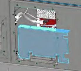
Handling and transportation
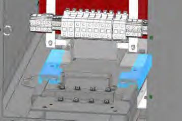
The instructions to be followed during transport of the equipment in sea containers, transport by truck, the lifting method and the materials required for handling and transportation are given in the Transport Guide (HEMGT02).

CAUTION
Wood or dunnage must not be used under the equipment when loading on the trailer or transport platform. The equipment must be placed on the trailer or the transport platform with nothing under it.
Follow the handling and transportation requirements described in the Transport Guide (HEMGT02). Any other method of transport or handling could damage the unit or void the warranty.
Suggested foundation NOTICE

The instructions on this section do not replace the internal regulations of each country.
Prior to installation, a geotechnical study of the terrain where the equipment will be installed must be carried out to determine its characteristics and decide the most suitable type of foundation.
It is the responsibility of the client to design and build the foundation.
Soil
The soil should have the following characteristics:
It must be dry, compacted, stable and homogeneous.
It must be gravel, ballast or pebble.
It must have hard or medium harshness characteristics.
The calculation of the maximum permissible pressure on the ground must comply with local and national standards, as well as with any other requirements regarding natural disasters (hurricanes, earthquakes, etc.) that may apply to the place of installation.
Do not install on floodable grounds.
The soil must be provided with drainage systems, especially in high water table and/or heavy precipitation sites.
It is recommended that the ground does not exceed the level of the foundation.
The minimum soil compaction degree is 98%.
The maximum slope is 0,25%.
The foundation slab must provide a solid and levelled surface for the equipment. It may be a concrete slab, concrete footings, steel piles or concrete pillars
Concrete slab
A layer of lean concrete is laid between the slab and the ground. The slab must comply with the following characteristics:
Dimensioning must be appropriate to the weight of the equipment. It must have trenches wide enough to guarantee proper cable passing (suggested size is shown below).
The slab must comply with minimum working distances around the equipment for its safe and correct operation. The dimensions of the slab will be shown below.
Thick enough to support the equipment.
Floodable foundations must be avoided.
The following figure shows an example of the equipment once placed in the foundation slab.
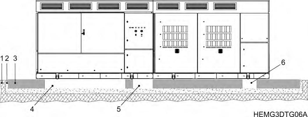
NUMBER IN FIGURE DESCRIPTION 1 Soil
2 Lean concrete
3 Foundation slab 4, 5, 6
Trenches for cable access: 4: DC cables access.
5: Auxiliary and SCADA connections. 6: AC output.
To allow cables passing, the slab must have four trenches: one for DC cables from the PV field, one for DC cables from the Freemaq DC/DC equipment (if necessary), one for AC output cables and one for auxiliary and SCADA connections.
As mentioned before, the slab must comply with the minimum distances shown below (top view), in order to have a safe and correct operation:
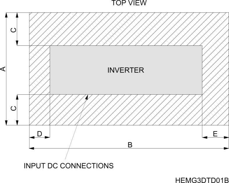

CAUTION
For proper electrical installation, it is very important to meet the cable curvature radius. For this, user must ensure cables enter the equipment perpendicularly and that spacing between them is appropriate. Connection terminals must not be overtightened.
In case there is any specification regarding variable actions such as snow, wind or earthquake, the slab must also meet the following requirements:
Ability to withstand compressive forces of 25 N/mm2.
Steel frame with capacity to withstand traction forces of 500 N/mm2.
Considering severe wind conditions (greater than 60 m/s) dimensions would be:
o The longitudinal side of the frame must be able to withstand forces up to 80 kN.
o The transverse side of the frame must be able to withstand forces up to 10 kN.
The following figure (footprint view) shows the dimensions of the slab and trenches for cable access, as well as their location in the slab. Please notice that thickness of the slab must be determined based on the results of the geotechnical study.

Note: The customer shall account for the tolerances in the trenches for cable access. These tolerances are +/- 2 cm (0.8 in.) in each direction of the trench.
Steel or concrete pillars
Whether steel or concrete pillars are used, it is recommended to use a ten (10) piers foundation, with two (2) anchorage holes per pillar. There should be as many anchorage holes as anchor points on the equipment. In case of reducing the number of pillars, the characteristics of the anchors should be checked.
The following image shows a footprint view of HEM inverters. For further details about anchorage dimensions, see section “Anchoring requirements”.
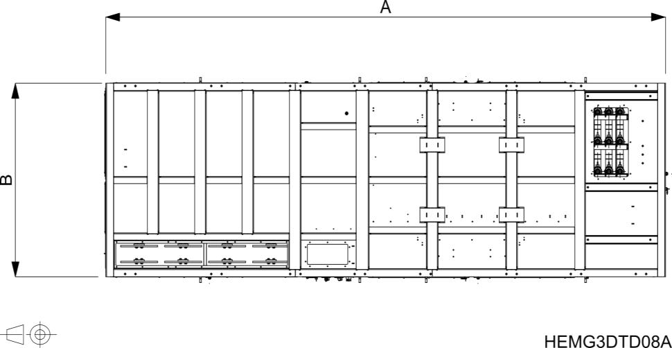

NOTICE
The design and construction of the structure with pillars, as well as their characteristics is responsibility of the customer.
In extremely hot places it is recommended to install the equipment with an elevation above grade of approximately 635 mm (25 in.) to allow additional air flow to maximize cooling.
It is recommended to build a slab above the pillars to facilitate access to the equipment and maintenance. The slab should be at least 1 m (40 in.) larger on each side of the inverter.
Failing that, some method of lifting must be available / provided at the plant to allow safe access to the equipment.
Anchoring must always be done with screws. They should not be welded to prevent corrosion problems and, specially, power electronics problems.
Any other anchoring system different from the one mentioned on this manual is not allowed and, in that case, the warranty will be voided.
With informative character, surfaces with concrete and steel pillars are shown up next:
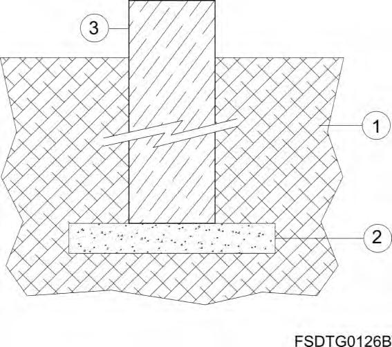

1 Please refer to section “Soil” to consult the characteristics of the terrain
Minimum working distances

CAUTION
Observe all minimum clearance requirements for electrical code, thermal and safety requirements. Refer to NEC 110.34 for additional clearance requirements for equipment above 1000 Volts.
The inverter is designed with thermal insulated cabinet doors to ensure optimum outdoor performance. For adequate inspection, cooling, operation and heavy vehicles with crane passing, it is important to leave a walkway around the equipment. The following figure shows the equipment front and footprint view with the recommended clearances:
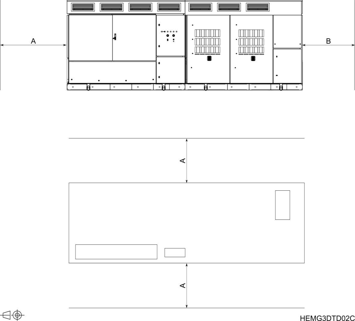
In case of installing several HEM GEN3 inverters, there should be a separation between them to allow a proper operation and heavy vehicles with crane passing. The distance must be greater than or equal to A = 2 m (6.5 ft) 2
The following figure shows the equipment footprint view with the minimum clearance:
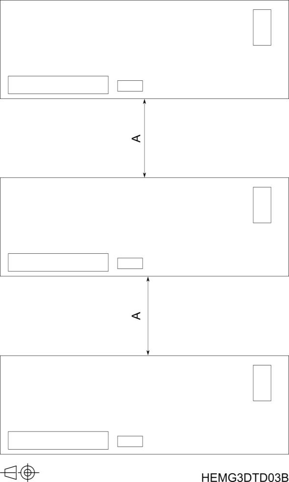
Note: For UL equipment, consult NEC 110.34 for additional clearance requirements for equipment above 600 Vdc.
When installing two inverters with theair outlets facing each other, it is necessary to increase the distance between them 3 m (9.8 ft) more to ensure the optimum performance of the cooling system, resulting in a total distance C of 6 m (19.7 ft).

2 Please contact with Power Electronics for further information depending on the project.
Anchoring requirements
To anchor the equipment in concrete slab, it is recommended to use M16 (5/8”) A4-70 stainless screws for high load solicitations, being accepted both expansive anchor bolts and chemical.
In the case of anchoring the equipment to a metal structure, the use of M16 (5/8") A4-70 stainless screws is recommended.
Please, secure them applying the recommended torque for mechanical connections (see section “Torque and screw sizing”) For more information consult Power Electronics
The following image shows the footprint view. Note that the anchoring points of the equipment will vary according to the seismic zone, see sections “Moderate seismic zone” and “High seismic zone” for more details.


NOTICE
It is recommended to drill the anchorage holes before placing the inverter in its final location.
Anchoring must always be done with screws. They should not be welded to prevent corrosion problems and, specially, power electronics problems.
Any other anchoring system different from the one mentioned on this manual is not allowed and, in that case, the warranty will be voided.
Moderate seismic zones
As mentioned above, the anchoringpoints will varydepending on the seismic risk regardless of whether the equipment is installed on slab, metallic structure, or pillars. The following image (footprint view) shows the location and distances between anchoring holes for moderate seismic zone
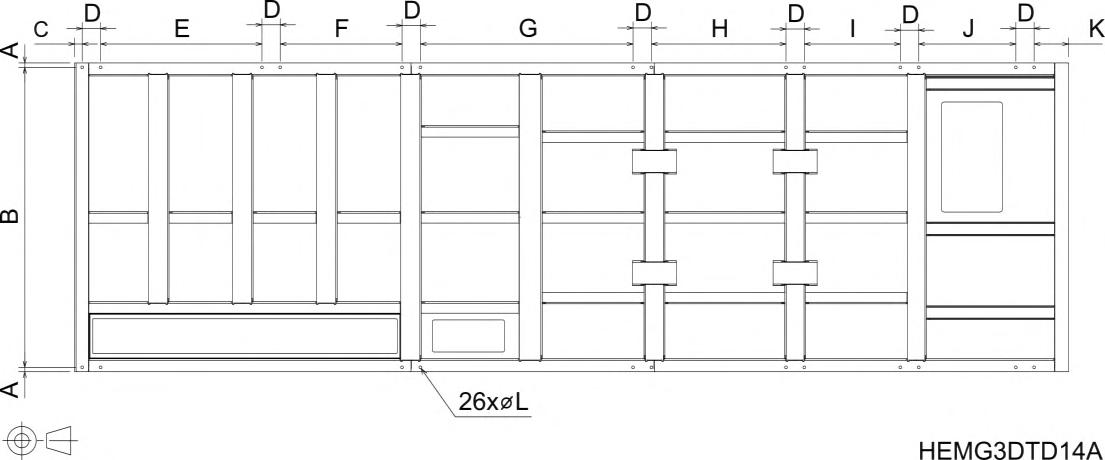
DIMENSIONS
In case of installation on pillars, the load distribution due exclusively to the weight of the inverter is shown below (footprint view).
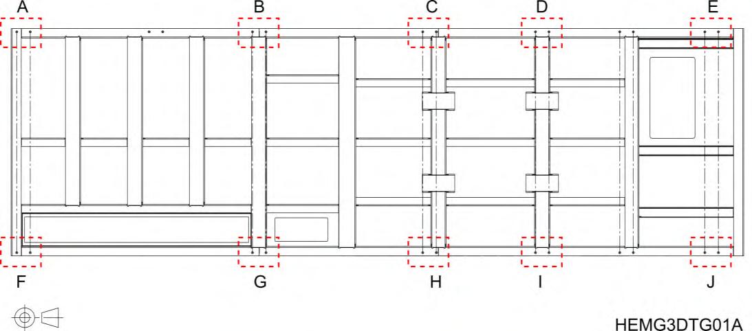
ANCHORING POINTS REACTIONS
High seismic zones
The following image (footprint view) shows the location and distances between anchoring holes of the station for high seismic zone. In this case, 13 additional brackets attached to each anchoring point are included to ease the installation.
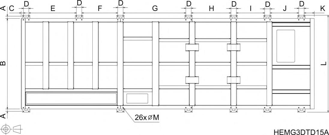
DIMENSIONS
In case of installation on pillars, the load distribution due exclusively to the weight of the station is shown below (footprint view):
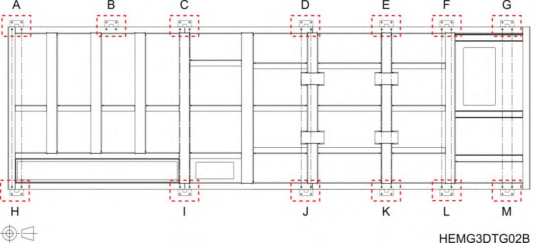
ANCHORING POINTS REACTIONS
Cooling system
Based on many years of experience with our MV Variable Speed Drive, the forced air-cooling system delivers a constant stream of clean air to the MV transformer without having to maintain cumbersome dust filters or having to use liquid-cooling systems, avoiding the commonly known inconveniences of it (complex maintenance, risk of leaks, higher number of components ), therefore resulting in an OPEX cost reduction.


Noise level
HEM inverters are designed to be installed in an industrial environment. The equipment noise level is below 79 dBA at a distance of 1 m (3.3 ft) from the back of the unit. Noise attenuation occurs as distance from the source increases.
5.WIRING ACCESS AND CONNECTION
The following figure shows the location of cable accesses for ground, DC and AC connections (footprint view).

Recommended screwing material is summarized in the table below. For more details and instructions on how to perform the connections, please keep on reading the following subsections.
ELEMENT RECOMMENDED SCREWS
Ground connection (1/4”) M6 x 30 mm, stainless steel. Torque depends on the screw quality.
DC connections 1/2” M12 x 50 mm, zinc steel Torque depends on the screw quality.
AC connections
- MV AC input from transformer
- MV AC output to grid
Included with the chosen elbow connectors. Torque depends on the elbow manufacturer’s connector installation instructions.

CAUTION
For proper electrical installation, it is very important to meet the cable curvature radius. For this, it is essential that the trenches are deep enough and in compliance with the recommendations from section “Suggested foundation” . Connection terminals must not be overtightened.
The removable gland plates are NOT pre-drilled or pre-marked. The installer is responsible to install the proper knockouts and watertight fittings in the gland plates before inserting the cables. See the images of the table below for a correct installation.


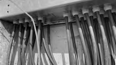
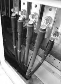
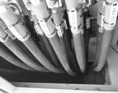


NOTICE
Consult the recommended tightening torque for both mechanical and electrical connections in section “Torque and screw sizing”.
Conductive paste should be applied in all connections: ground and DC connection.
Paste for electrical conductors helps to improve and protect any electrical contact Al - Al, Al - Cu and Cu - Cu exposed outdoors, allowing the reduction of electrical resistance and the sealing of the contact parts to avoid corrosion. The working temperature range of this paste should be between -40ºC and 150ºC (-40ºF to 302ºF).
In case of doubt choosing a commercial reference of conductive paste, please contact Power Electronics.
Ground connection
The equipment has common ground and most connections are factory made. User only must connect the main ground busbar, located in the medium voltage switchgear, and, if there is any external connection that the user should do, connect it to the user connections ground busbar
In the MV switchgear cabinet, at the AC cables access side, can be found:
MV transformer ground busbar. Factory wired (user does not need to make any connections).
Main ground busbar which, in turn, is divided into two pieces. These two busbars are joined by a bonding plate. If the plate is removed, the equipment will be isolated from ground.
The following figure shows the location of the ground busbars that the user must connect (top view):
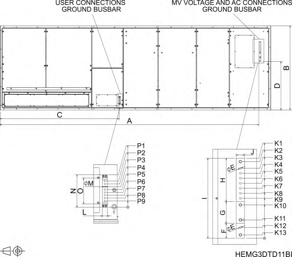

NOTICE
User must connect the installation’s ground cable to the smaller piece and the equipment’s ground cable to the bigger piece of the main ground busbar
Besides, there is a ground busbar for the DC side of the equipment in the DC cabinet (see “DC connections from PV field”) In this busbar, the user should connect the DC cable meshes from PV field
The MV voltage and AC connections ground busbar is made of nickel-plated copper and the user connections ground busbar is made of tinned aluminum. Connections should be done considering the following recommendations.
Before connecting the cables, clean the contact surfaces with a clean cloth and ethanol cleaner. The ground cables must enter the equipment through the removable metal plate located in the bottom of the cabinet. Each cable must be routed in the equipment only with conduit hubs or fittings rated as 3, 3S, 4, 4X, 6 or 6P according to UL 514B.
Apply conductive paste between the terminals and the plates to improve and protect any electrical contact Al - Al, Al - Cu and Cu - Cu exposed outdoors, allowing the reduction of electrical resistance and the sealing of the contact parts to avoid corrosion. The working temperature range of this paste should be between -40ºC and 150ºC (-40ºF to 302ºF).
It is recommended to use Ø11 (3/8”) copper, aluminum or copper-clad aluminum 1-hole terminal lugs with a maximum width of 45 mm (1-3/4”).
Use M6 x 30 mm (1/4”) bolts and nuts and apply the recommended torque according to the quality (See section “Torque and screw sizing”) User connection ground busbar requires 1/4" bolts and nuts.
Use a spring washer and a fender washer between the nuts or bolts head and the busbar or terminal lug.
The earth of cable meshes from the PV field must be connected to the ground terminal in the DC cabinet (see detail in DC Connections section).
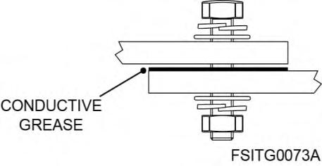

NOTICE
User only has to make the connections of the main ground busbar, located at the MV switchgear cabinet. Ground connections of the DC side and the MV transformer are factory made.
DC connections from PV field
DC+ and DC- cables must be routed from beneath the equipment, through the metallic panel located in the bottom and connected to the input plates. Each cable must be routed in the equipment only with conduit hubs or fittings rated as 3, 3S, 4, 4X, 6 or 6P [1]
Recommended cable section for DC connections is 250 mm2 for IEC normative and 450kcmil for UL normative. The maximum admissible cable section for DC connections for IEC and UL normative, respectively, is:
400 mm2 (750 kcmil) for connection of one cable per terminal.
300 mm2 (600 kcmil) for connection of two cables per terminal.
[1] Applies for UL 514B.
Additional considerations to take into account:
The connection of more than two cables per terminal is not allowed. In this case, the operation of the equipment may be compromised, and the warranty may be voided.
In equipment with individual terminals, when choosing the cable to be used, it must be taken into account that the maximum current supported by each individual terminal is 400A.
To isolate the DC side of the inverter module from the PV field, four switch disconnectors located in the DC cabinet (one per module) are used, and to isolate the DC input cables from fuses, optional manual disconnectors can be used.
HEM inverters present a DC input protected by four switch disconnectors (one per module), located in the DC cabinet.
The following image shows the location of DC busbars:

The distance from the gland plate to the bottom of the base frame or ground level in the DC cabinet is 18 mm (0.70 in.)

NOTICE
Only use the bottom removable panel to route the DC cables
In case fuses are not factory installed at the equipment, please, refer to document HEMG3IC04 Please notice that there are different configurations available for DC cabinets depending on the project and options chosen by the customer

WARNING
A PV inverter is a dual power source. There may be voltage present, from the photovoltaic generator and/or the high voltage network. It is especially important to consider this when disconnecting parts of the system.
The input configuration and the fuse values must be selected according to the PV installation characteristics and meet all code requirements. It is the responsibility of the installer to select the proper overcurrent values.
Up to 1500 Vdc may be present in BSS. Use LOTO procedures to ensure the system is safely deenergized prior to making connections.
DC busbars are made of tinned aluminum. Connections should be done considering the following recommendations.
Before connecting the cables, clean the contact surfaces with a clean cloth and ethanol cleaner.
It is recommended to use Ø13 (0-1/2”) copper, aluminum or copper-clad aluminum 2-hole terminal lugs with a maximum width of 45 mm (1-3/4”).
Lugs with a temperature rating of either 75 ºC or 90 ºC (167 ºF or 194 ºF) are acceptable for DC terminations.
Use copper, aluminum or copper-clad aluminum 75 ºC (167 ºF) cables with conductor size according to Table 310.16 of the National Electrical Code, ANSI/NFPA 70 for this Temperature rating of wire. As an alternative, use copper, aluminum or copper-clad aluminum 90 ºC (194 ºF) cables with conductor size according to the same NEC table. In all cases, cables must have a minimum rated voltage of 1500 V.
The use of fully covered cables is recommended. In case any part of the cable is bare, a minimum distance of 20 mm (0.79 in.) must be respected.
Apply conductive paste between the terminals and the plates to improve and protect any electrical contact Al - Al, Al - Cu and Cu - Cu exposed outdoors, allowing the reduction of electrical resistance and the sealing of the contact parts to avoid corrosion. The working temperature range of this paste should be between -40 ºC and 150 ºC (-40 ºF to 302 ºF).
Use M12 x 50 mm [2] (1/2” x 19 7”) bolts and nuts and apply the recommended torque according to the quality (See section “Torque and screw sizing”).
2 Maximum length.
In case of needing to turn the bolts for an easier connection, the minimum safety distances between metallic parts must be kept (20 mm / 0 79“)
Use a spring washer and a fender washer between the nuts or bolts head and the busbar or terminal lug.
The earth of cable meshes must be connected to ground.
The following figure shows the correct connection:
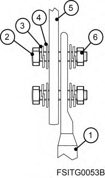
Ref. Element
1 Terminal lug
2 M12 (1/2”) bolt
3 Spring washer
4 Fender washer
5 Plate
6 M12 (1/2”) nut
Note: If the terminal is a single-hole terminal, it is recommended to connect it to the upper hole in the busbar, so that the contact area is maximized.
The following image shows the suggested terminal dimensions:
Bus Plus (optional)
HEM inverters include the Bus Plus configuration. This mode consists of a connection located on the DC side that allows the equipment to be connected to an energy storage system through Freemaq DC/DC battery management equipment.
The Bus Plus Basic configuration allows to connect up to 2 Freemaq DC/DC.
The Bus Plus Advanced configuration (optional) allows to connect up to 4 Freemaq DC/DC.
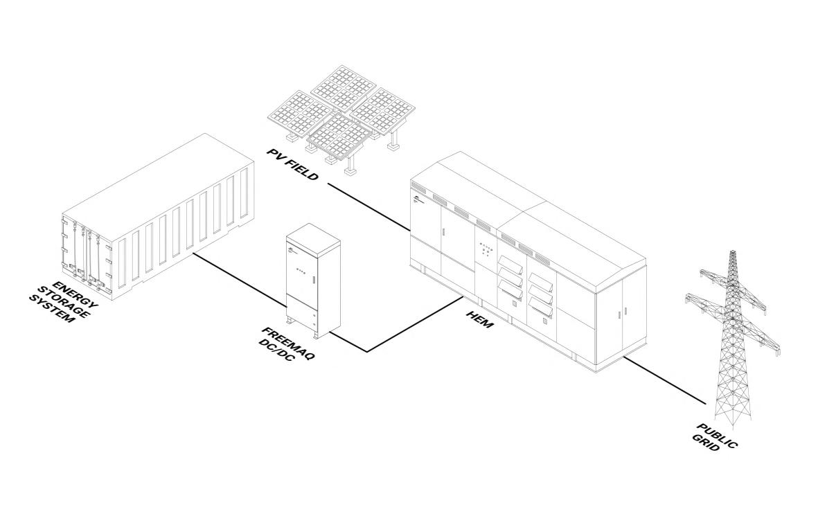
If this configuration is used, the equipment is able to work in clipping recovery mode. This mode consists in diverting the excess of energy to a storage system in peak hours and inject this energy to the grid in low hours

NOTICE
If the Bus Plus connection is factory installed and not performed at the moment, it is possible to make the installation in the future. In this case, it is important to foresee the cable access when building the foundation Refer to section “Suggested foundation”
The optional Bus Plus configuration for HEM inverters is compatible exclusively with Freemaq DC/DC of Power Electronics.
For screwing size and connection recommendations, follow the instructions given in section “DC connections from PV field”.
Apply conductive paste between the terminals and the plates to improve and protect any electrical contact Al - Al, Al - Cu and Cu - Cu exposed outdoors, allowing the reduction of electrical resistance and the sealing of the contact parts to avoid corrosion The working temperature range of this paste should be between -40 ºC and 150 ºC (-40 ºF to 302 ºF).
AC connections

WARNING
Access to the MV switchgear cabinet is only allowed once all voltage sources have been removed. Otherwise, you could get an electric shock. Refer to the “Safety instructions” for further details and an illustrative figure.
Once AC connections have been finished, lock the plate of the MV switchgear cabinet by using the square polyamide lock. Once locked, the access plate should never be opened, even if PPE is used, unless user has made sure there are no voltages present. Otherwise, you could get an electric shock.

NOTICE
User is strongly advised to install a surge protection device (SPD) at the end of each high voltage line.
Medium voltage cables must be selected according to the line voltage of the installation.
The AC connection terminals are compatible with copper terminal, bimetallic terminal and zinc aluminum terminals. Power Electronics recommends the use of elbow connectors.
User must perform the connections L1, L2 and L3 in the AC terminals. It is recommended to follow these steps to ensure proper and enduring AC connections:
1. Remove the bottom metallic panel. Mark and drill the holes for cable access. Install proper cable glands and watertight fittings. Once finished, install the panel again.
2. Route AC cables from beneath the equipment, through the bottom metallic panel.
3. Pass each cable through a clamp and secure it. Connect also the cable ground to the ground busbar. The MV cable clamps provided with the equipment can accommodate MV cable up to maximum 41 mm (1.6 inch.) outside diameter. If larger non-standard MV cable clamps are needed contact Power Electronics.
4. Connect the elbow connectors to the AC terminals. Ensure connectors are free of moisture or dust and use grease to ease the connection. Tighten according to the MV switchgear manufacturer’s instructions3
3 Please notice that maximum torque is limited by the MV switchgear characteristics. Refer to MV switchgear manufacturer’s instructions to consult the torque limit and recommended torque value.
The following image shows the location of AC busbars and its R, S and T terminals, cable clamps and the bottom plate.
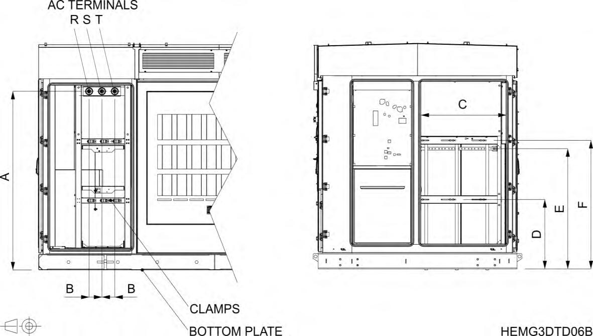
The distance from the gland plate to the bottom of the base frame or ground level in MV switchgear cabinet is 160 mm (6.30 in.).
User cabinet connections
In the event of a control switchgear connection, the customer must make the connection to the rail reserved for the user on the control side of the user cabinet.

WARNING
Do not make any modifications (drilling, mechanical changes, etc.) on the user cabinet.
The use of PPE is recommended to open the doors of the user cabinet and to perform any actions on it.
The following image shows the main user cabinet distribution 4. This cabinet corresponds to door 18 in section “Cabinets distribution” In the picture it can also be observed the RJ45 wiring path for the user's SCADA connection and the 208 Vac power supply. The ground busbar is located in the bottom right side of the cabinet.
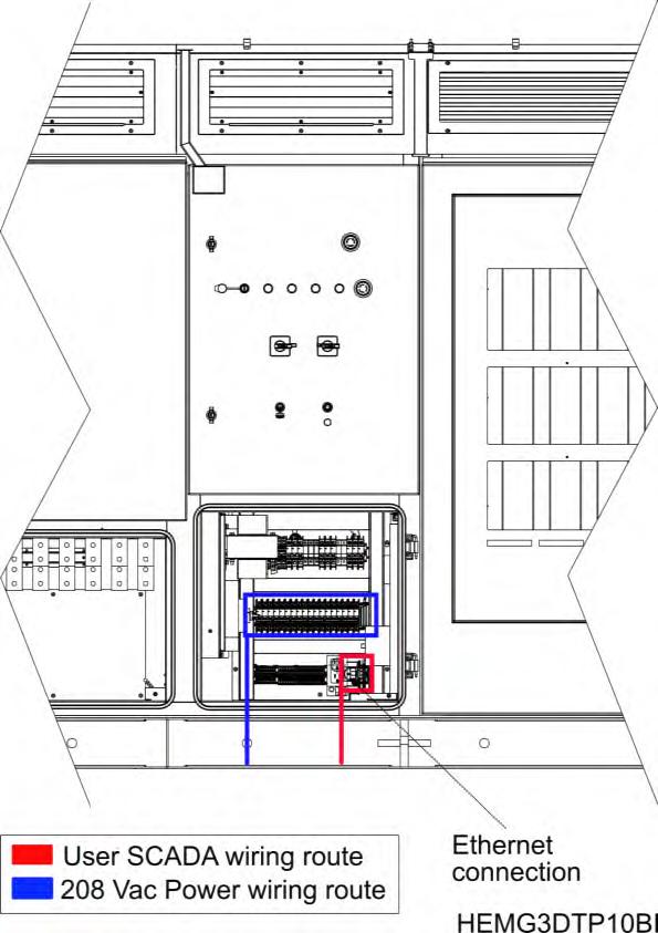
The distance from the gland plate to the bottom of the base frame or ground level in the user cabinet is 163 mm (6.42 in.).
On the right side of the user cabinet there is an optional user control cabinet. There is a communication switch with ST, SC connections or a patch panel for customer connections. The customer must use single mode 62.5 / 125 m fiber and SC connectors or single mode 50 / 125 m fiber and ST connectors.
On the left side of the user cabinet there is an optional user option panel. This panel is installed only when the optional Econ Mode AC is chosen, it includes a 230 Vac or 120 Vac Econ Mode connection point for the customer.
4 The user cabinet distribution may change depending on project characteristics.
6.PROTECTIONS
Power Electronics HEM inverters are equipped with several hardware protections that complete the software protections, please consult according to the project. Besides, HEM includes the latest utility interactive features (LVRT, OVRT, FRS, FRT, Anti-islanding, active and reactive power curtailment ), and can be configured to meet specific utility requirements.
Overvoltage protection
AC Cabinet
The AC main circuit overvoltage suppressor is installed in the AC cabinet, (number 11 in figure “Cabinets distribution”) is equipped with three overvoltage arresters with varistors. Their main characteristics are:
Rated voltage (Un)
AC overvoltage suppressor (P01, P02, P03)
Voltage protection level (Up)
Rated discharge current 8/20 µsec (In)
Vac 5 kV 15 kA
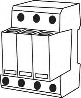
The auxiliaries’ overvoltage suppressor is composed by removable modules that include a fault indication window. These modules can be replaced by using the top and bottom pushbuttons, as shown in the following figure:
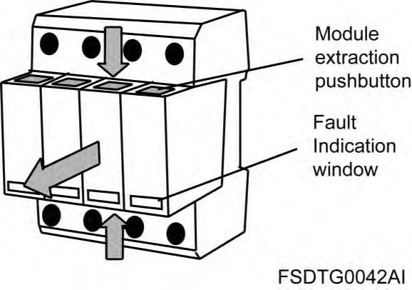
Main circuit protection
DC Cabinet
The four DC switch disconnectors are installed in the DC cabinet, beneath the modules (number 15 and16infigure“Cabinets distribution”).Theirmaincharacteristicsare:
DC power supply circuit breaker (SI01, SI02, SI03, SI04)
AC Cabinet
The 3 poles fuse switch disconnector of the auxiliariestransformer’sprimary are installed in the AC cabinet(number11infigure“Cabinets distribution”).Dependingonthetypeoftransformerwhichhas been installed, the characteristics of the fuses will vary:
Forauxiliaries’transformer73KVA UL:
Note: In case the project includes a transformer different to those mentioned above, consult with Power Electronics the recommended fuses characteristics.
Finally, at the MV switchgear cabinet, there is a protection cell with the following characteristics:
Main control cabinet
The auxiliaries’voltagecircuitbreaker (general magneto-thermal Q03) is located in the main control cabinet(number13infigure“Cabinets distribution”).Itprotectstheauxiliaryventilationandhasthe following characteristics:
(kA)
Auxiliaries’voltage circuit breaker (Q03)
The auxiliaries’supplyfuses are also located in the main control cabinet. Their main characteristics are:
Type Rated current (In) Rated voltage (Un) Breaking capacity (kA)
Auxiliary fuses (F09, F10) aM 10x38 mm 20 A 400 Vac 120 kA
Optional auxiliary fuses for Econ mode (F11, F12)
Finally, at the main control cabinet, the control supply (24 V) from the control panel towards the modules, the DC cabinet and the Main Control Cabinet, are protected using electronic fuses:
Rated current (In) Rated voltage (Un)
Electronic fuses (F16, F17, F18, F19) 12 A 124 Vdc
Ground fault protection
The ground fault protection circuitry is located at the DC cabinet (number 13 and 14infigure“Cabinets distribution”). It may vary depending on the installation.
The battery inverter is equipped with an insulation monitor as standard. This detector monitors the insulation resistance of the equipment and batteries to ground, providing early indication of faults before leakage current may even be present. For further information, contact Power Electronics.
VRT ( Voltage Ride Through)
Inverters can withstand any voltage dip or profile required by the local utility. The equipment can immediately feed the fault with full reactive power, as long as the protection limits are not exceeded.

F/P function
F/P (frequency/power) function defines the active power along a pre-set characteristic curve supporting grid stabilization.

V/Q function
It is a dynamic voltage control function which provides reactive power to maintain the voltage as close as possible to its nominal value.
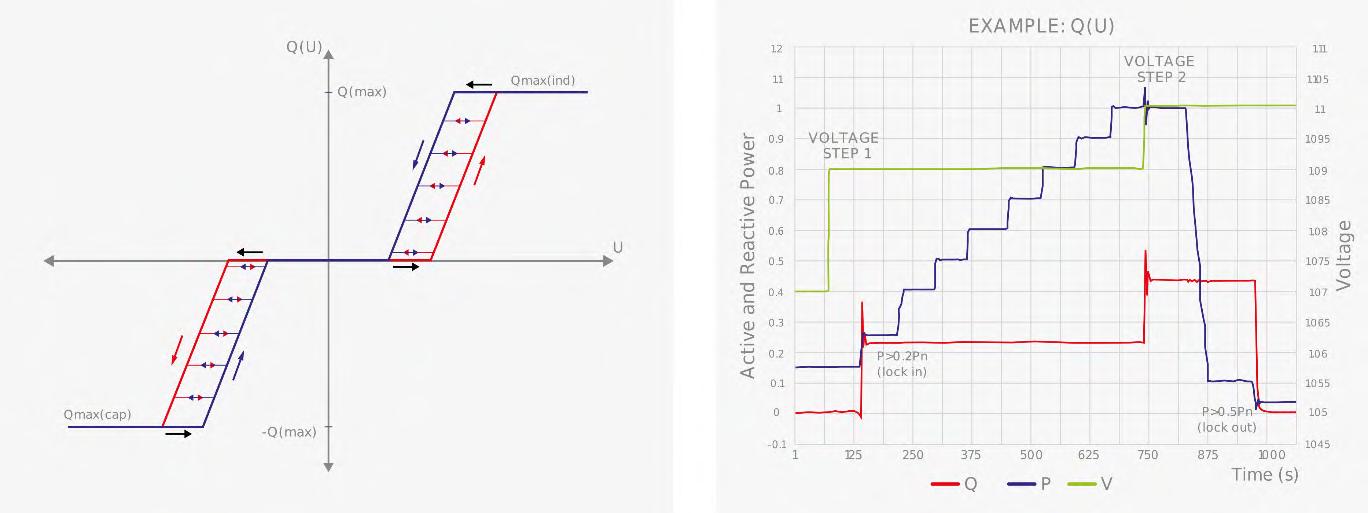
FRT (Frequency Ride Through)
HEM solar inverters have flexible frequency protection settings and can be easily adjusted to comply with future requirements.

Anti-islanding
Anti-islanding protection can be passive, active or a combination of both. This protection allows detecting island situations and lead to disconnection.
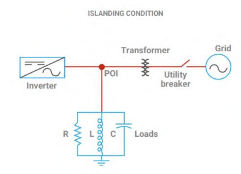
7.LEDS
AND CONTROLS
LEDs and controls
The following control elements and indicator LEDs can be found on the door of the AC control cabinet.
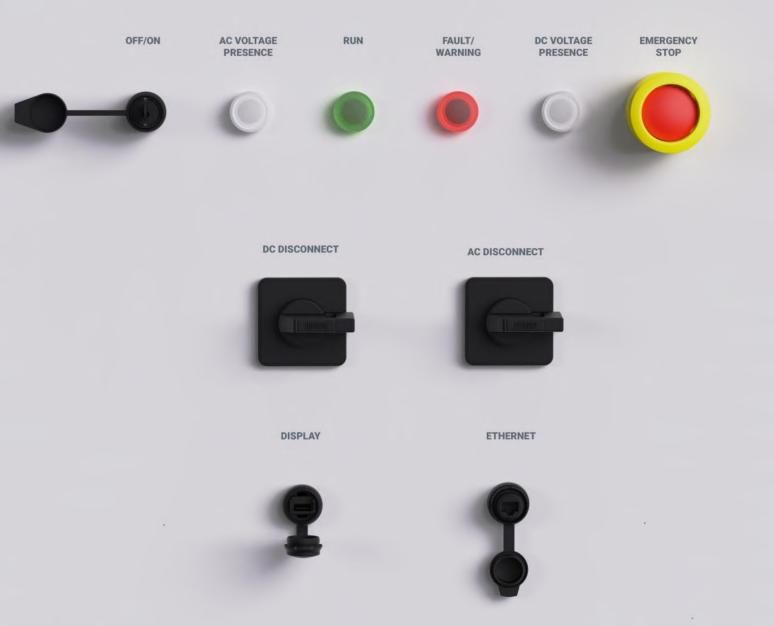
ON/OFF switch key: Allows turning OFF and ON all inverter modules. Run, AC Voltage and Fault LEDs: Show the operation status of the equipment, according to the following table:
COLOR LED ON LED OFF
AC Voltage White AC Voltage presence No AC voltage presence
DC Voltage White DC Voltage presence No DC voltage presence Run Green Equipment ON Equipment OFF Fault Warning Red A fault has occurred No faults
AC Disconnect: Disconnector. Allows disconnecting AC voltage.
DC Disconnect: Disconnector. Allows disconnecting DC voltage.
STOP: Pushbutton. Allows stopping the equipment in case of an emergency situation.

Do not use the emergency pushbutton to perform regular stops on the equipment. It should only be used when an emergency occurs. Otherwise, longevity of the main components could be shortened and result in equipment damage.
The DC Disconnect pushbutton should only be used for LOTO procedures.
DISPLAY: USB port. Allows connecting the display unit to the Main Control Cabinet door.

ONLY use the DISPLAY port to connect the display unit. Do not connect other USB devices. Otherwise, the port may get permanently damaged and you may cause equipment malfunctioning.
ETHERNET: RJ45 port. Allows connecting an Ethernet cable in the Main Control Cabinet door to access the equipment’s network
Display unit and control keypad (optional)
Power Electronics external display, available upon request, is a graphic monochromatic 2 8” screen that provides intuitive data representation and easy navigation through parameters. Additionally, it allows storing thousands of customized configurations.
The graphic display is an external unit and must be connected at the Main Control Cabinet’s door USB port. It integrates a LED indicator that supplies information about the equipment operational status and eight control keys. This display is not provided with the inverter.

Consult the Software and Programming Manual for more information.

NOTICE
If the customer acquires the display (optional), it must beconnected to the corresponding external port Use a cable with a micro USB male terminal on one end and USB male terminal on the other.
ONLY use the DISPLAY port to connect the display unit. Do not connect other USB devices. Otherwise, the port may get permanently damaged and you may cause equipment malfunctioning

CAUTION
Commissioning must only be performed by qualified personnel approved by Power Electronics Read carefully these instructions and all safety recommendations. Otherwise, equipment may get damaged and personnel seriously injured.
Ensure no voltage is present in power terminals. Ensure power supply cannot be connected unexpectedly.
The instructions on this manual do not override nor replace local or national regulations. It is the user’s responsibility to comply with all safety standards that apply to the site of installation.

NOTICE
For “Cold Commissioning” and “Hot Commissioning” detailed procedures, please refer to documents HEMG3IC01 and HEMG3IC02, respectively.
9.OPERATION
The equipment integrates some complex operation modes that are explained in this section.
Safe stop and start up maneuvers
Safe stop and start up maneuvers, as well as LOTO (Lock Out Tag Out) procedures, are explained in detail in the Maintenance Manual. Please refer to this document and ensure it is the latest edition.

WARNING
Before opening any of the doors, ensure to follow the isolation guidelines and all safety instructions. Otherwise, you could get an electric shock.
Under no circumstances the AC circuit breaker or the MV switchgear should be closed without first performing the soft charge of the DC bus in each power stage. This implies that manual closing of the MV switchgear or AC circuit breaker is not allowed. Connecting the equipment to the grid without having previously performed the soft charge of the DC bus, would lead to the destruction of the power stage. Therefore, the equipment must always be started up and connected to the grid in a control way, being the connection of the equipment to the grid managed by the software of the equipment.

NOTICE
Safe stop and start up maneuvers are detailed in the Maintenance Manual. Ensure you have the latest edition.
Night mode
At night, the HEM inverter can shift to reactive power compensation mode. The inverter can respond to an external dynamic signal, a Power Plant Controller command or a pre-set reactive power level (kVAr).
Check the Programming and Software Manual for more information.
Active heating
At night, when the unit is not actively exporting power, the equipment can import a small amount of power to keep its internal ambient temperature above 5 °C (41 ºF) and a relative humidity of 65% without using external resistors. This autonomous heating system is the most efficient and homogeneous way to prevent condensation, increasing the equipment availability and reducing the maintenance. Besides, a heating resistor kit will be required to start at temperatures below -25 ºC (-13 ºF).
Econ Mode (optional)
This innovative control mode allows increasing the efficiency of the MV transformer up to 25%, reducing the power consumption of the plant and therefore providing considerable savings.
Available as an optional kit for UL HEM inverter, this feature has a pay-back time of less than a few years, therefore resulting in the increase of the plant lifetime overall revenue.
Insulation Monitoring Device
The DC Insulation Monitoring Device (IMD) installed in the Freesun HEM solar inverters, is an innovative solution - Software and hardware- developed by Power Electronics to measure the impedance between the positive pole and ground and between the negative pole and ground.
Due the electrical connection between the DC side and AC side of the inverter does not have galvanic separation, and only when the inverter is injecting power, all the pulses generated by the insulation monitor are also transmitted to the AC bars, being possible to detect any insulation fault in the entire circuit.
Configuration and operation of the insulation monitoring
For the insulation measurement, the monitoring injects pulses between the poles and ground. The impedance is calculated through the obtained tau (the tau is a function of the RC ground impedance).
This impedance measurement is compared with the warning and fault threshold defined in the equipment software. Refer to the Software and Programming Manual for more information.
The operation logic is as follows:
If the measured resistance is lower than the configured resistance warning threshold, the IMD (Insulation Monitoring Device) will send a warning message to the control central board of the inverter. The inverter will display a warning in order to notify the situation.
If the measured resistance is lower than the configured fault threshold, the insulation monitoring will send a warning message to the control central board of the inverter. In this case the inverter will stop operating until the fault detected by monitoring has been solved.
10. MAINTENANCE

WARNING
Before opening any of the doors, ensure to follow the isolation guidelines and all safety instructions. Otherwise, you may get an electric shock.

CAUTION
Maintenance tasks must only be carried out by qualified personnel approved by Power Electronics. Otherwise, equipment may get damaged and personnel seriously injured.

NOTICE
Maintenance tasks and recommendationsare detailed in the Maintenance Manual. Ensure you have the latest edition.
The equipment has been developed based on a revolutionary design concept that significantly simplifies the tasks and reduce the times of preventive and corrective maintenance. Nevertheless, some preventive actions and checks are required. They are described in detail in the Maintenance Manual.
HEM GEN3
MAINTENANCE MANUAL


UTILITY SCALE CENTRAL STRING INVERTER
Maintenance Manual
Edition: February 2023
HEMG3MTM03CI Rev. C
ABOUT THIS MANUAL
PURPOSE
This manual contains important instructions for the installation, configuration and use Power Electronics Freesun inverters HEM GEN3.
TARGET AUDIENCE
This manual is intended for operators of Power Electronics HEM GEN3 Freesun Inverters, which during the warranty period must be certified by Power Electronics to perform the required maintenance. The operator is only responsible for the six-month maintenance (type A).
Power Electronics must perform the rest of the maintenances on the inverter and will reserve the right to train operators for these advanced maintenance tasks.
A certified operator does not gain capabilities to autonomously execute the advanced maintenance but will give the opportunity to join Power Electronics to complete the maintenance between the two parties.
Power Electronics is not responsible for scheduling preventive maintenances, the operator must notify Power Electronics when a maintenance is due (with at least 1 month in advance).
The below points may void the warranty of the equipment.
Failure in executing and adequately reporting maintenances.
Failure in informing Power Electronics of scheduled maintenances.
REFERENCE MANUALS
The following reference documents are available for the Freesun HEM GEN3 Inverters:
Hardware and Installation Manual.
Maintenance Manual.
Software and Programming Manual.
In addition, please, consult the annexes to this manual.
POWER ELECTRONICS CONTACT INFORMATION
Power Electronics USA Inc.
1510 N. Hobson Street, Gilbert, Phoenix AZ 85233
UNITED STATES OF AMERICA
US Sales: 602-354-4890 / (480) 519-5977
Power Electronics España, S.L. Polígono Industrial Carrases RondadelCampd’Aviaciónº4 46160, Llíria (Valencia) SPAIN
Telephone: (+34) 96 136 65 57
Website: www.power-electronics.com
REVISIONSCONTROL
DATE(DD/MM/YYYY) REVISION DESCRIPTION
04 / 03 / 2022
22 / 12 / 2022
17 / 02 / 2023
A First edition.
B Acronyms. Torque and screw sizing. Safe and start up. Six-monthly maintenance. Annual maintenance. Biannual maintenance. Four-yearly maintenance.
C About this manual. Safety instructions. Introduction.
The equipment and technical documentation are periodically updated. Power Electronics reserves the right to modify all or part of the contents of this manual without previous notice. To consult the most updated information on this product, you may access our website www.power-electronics.com, where the latest version of this manual can be downloaded. The reproduction or distribution of the present manual is strictly forbidden unless express authorization from Power Electronics.
ACRONYMS
ThetermscommonlyusedinthedocumentationofPowerElectronics’productsarelistedinthetable below.
Please notice this is a general series of terms and it encompasses all our product divisions (industrial, solar, storage, and electric mobility), thus, some of the following expressions may not apply to this particular manual.
ACRONYM MEANING
AASS Auxiliary Services
AC Alternating Current
AI Analogue Input
AO Analogue Output
BESS Battery Energy Storage System
BMS Battery Manager Solution
CCID Charge circuit interrupting device
CCL Charge Current Limit.
CCS Combined charging system – charging and communications protocol following the standard IEC 61851-23 Annex CC
CHAdeMO Charging and communications protocol following the standard IEC 61851-23 Annex AA
CPU Central Processing Unit
DC Direct Current
DCL Discharge Current Limit
DI Digital Input
DSP Digital Signal Processor
DO Digital Output
EMS Energy Management System
EV Electric Vehicle
FPGA Programmable device (Field-Programmable Gate Array)
FRU Field Replaceable Unit
GFDI Ground Fault Detector Interrupter
GPRS General Packet Radio Services, a data transmission system
HVAC Heating, Ventilation, and Air Conditioning
IGBT Insulated Gate Bipolar Transistor
IMI Insulation monitoring device
IT Grid system where the power supply is kept isolated and the electrical equipment system is grounded.
LOTO Lock Out – Tag Out
MCB Miniature Circuit Breaker
MCCB Moulded Case Circuit Breaker
MPCS Multi Power Conversion System
MID Measuring Instrument Directive
MV Medium Voltage. This term is used to refer to high voltage in general
PE Ground connection
PI Proportional and Integral
POI Point Of Interconnection
ACRONYM MEANING
PPE
Personal Protection Equipment
PV Photovoltaic energy
RCD
RCM
Residual Current Device
Residual Current Monitor
RFID Radio Frequency Identification
SOC State Of Charge – referred to battery
SOH State Of Health – referred to battery. It compares the actual state of the battery to its initial conditions. It is measured in percentage
STO Safe Torque Off
TN Grid system where the power supply is grounded, and the electrical equipment system is brought to the same ground through the neutral connector.
TT Grid system where both the power supply and the electrical devices are connected to the ground via separate connections
UPS Uninterruptible Power Supply
VSD / VFD Variable Speed Drive, Variable Frequency Drive. Both terms are used
SAFETY SYMBOLS
Always follow safety instructions to prevent accidents and potential hazards from occurring.
In this manual, safety messages are classified as follows:

WARNING

CAUTION

NOTICE
Identifies potentially hazardous situations where dangerous voltage may be present, which if not avoided, could result in minor personal injury, serious injury or death.
Be extremely careful and follow the instructions to avoid the risk of electrical shocks.
Identifies potentially hazardous situations, which if not avoided, could result in product damage, or minor or moderate personal injury.
Read the message and follow the instructions carefully.
Identifies important measures to take in order to prevent damage equipment and warranty lost, as well as encouraging good use and environmental practices.
Other symbols used in this manual for safety messages are the following:


Hot surface. Be careful and follow the instructions to avoid burns and personal injuries
Risk of fire. Be careful and follow the instructions to prevent causing an unintentional fire
Caution, risk of electric shock. Energy storage timed discharge. Wait for the indicated time to avoid electrical hazards.
Caution, risk of hearing damage. Wear hearing protection.
SAFETY INSTRUCTIONS
IMPORTANT!
Read carefully all documentation before manipulating the equipment and pay special attention to safety recommendations to maximize the performance of this product and to ensure its safe use and installation. This document encompasses the most important and frequent potential causes of damage to the equipment or personnel It is the installer’s responsibility to follow the instructions provided on this manual, to follow good electrical practices and to identify all mentioned warnings and recommendations before starting up and operating the inverter.
When workers are working in plants, they must be always accompanied by someone, and never can work alone. There will be always a Site Supervisor figure into the work party, who is in charge of the other workers, either technically either in Health and Safety actions.

WARNING
Before installing the HEM inverter, read all instructions and cautionary markings. Follow all instructions from the Hardware and Installation Manual. Failure to follow the safety instructions could result in severe shock or even death. Exercise extreme caution always to prevent possible accidents.
Ensure the inverter is completely disconnected from the power supplies and connected to ground before manipulating it or performing any maintenance tasks. Otherwise, electric shock hazard exists. To prevent electrical hazards, disconnect input supply, connect the equipment to ground, remove all control voltages before carrying out any task and ensure busbars are completely discharged. Warning and safety labels must be properly placed in terminals, enclosures and control panels according to local normative in force.
In addition to the recommendations on this manual, local and site-specific safety procedures must be taken into account. Also, national and local electrical codes must be followed in order to avoid personal injuries and/or equipment damage.
Failure to comply safety instructions and electrical codes may void the warranty.
When working in electrical installations always remember to apply the FIVE GOLDEN RULES:
1. Visible cutout of all sources in voltage.
2. Mechanical locking of all cutting elements.
3. Check the absence of voltage using appropriate tools for the installation voltage.
4. Ground and short-circuit all possible voltage sources.
5. Define and mark the work area.

NOTICE
Consult LOTO procedure in section “Safe stop of HEM”
Always follow local regulations or standards regarding H&S as well as internal application procedures.

WARNING
Do not connect any supply to the equipment while the doors are open. Otherwise, you could get an electric shock.
Do not apply power to a damaged inverter or to an inverter with missing parts even if the installation is complete. Otherwise, you could get an electric shock.
Keep all doors and covers closed during equipment operation. Otherwise, you could get an electric shock
Before opening any doors or covers, ensure to follow the isolation guidelines and all safety instructions. Otherwise, you could get an electric shock.
Always operate switches with dry hands and use personal protective equipment (PPE). Otherwise, you could get an electric shock.
Any tasks performed in the inverter must be carried out with, at least, two operators. The inverter should never be operated by a single operator.
Do not use cables with damaged insulation. Do not subject the cables to abrasions, excessive stress, heavy loads or pinching. Otherwise, you could get an electric shock.
Ensure compliance of all safety regulations for medium voltage operations that are in force at the place where the inverter is installed. Otherwise, you could get an electric shock.
In case the inverter stops due to a power loss, do not perform any works on it. Automatic restart function might be enabled, and you could get an electric shock.
Always follow proper lockout/tagout procedures.


5 min
The device contains capacitors on the AC and DC sides. The discharge time of the capacitors is 5 minutes. Wait until the capacitors have been discharged before carrying out any maintenance task.
Risk identification
The hazards associated with this specific activity and the necessary PPE to use are identified below. For further information, please refer to the risk assessment.










REQUIRED PERSONAL PROTECTION EQUIPMENT (PPE from now
on)
PPE is required according to standards for repairing and maintaining HEM inverters. Always follow the site operative instructions to fulfil the compliance of national or local normative.
A detailed example of PPE used will be shown below. Customer must specify in his safety instructions (risk assessment and method statements) which ones are the PPE required and when and how it should be used according to his electric arc studies, the characteristics of site, battery inverters, installation and country.
Power Electronics assumes no responsibility or liability for any damages resulting from inappropriate use of the equipment or failure to comply national or local regulations.
The following table includes just an example of commonly used PPE for installation. Always follow local regulations / NFPA-70E standard about H&S.


Electrical works


Auxiliary items





The following table shows the protection class type, depending on the working voltage.

NOTICE
LOCKOUT / TAGOUT (LOTO)
Lockout / tagout standards establish procedures to protect personnel from hazardous energy sources on equipment during service and maintenance. Refer to OSHA 29 CFR, part 1910.333 for lockout / tagout rules and requirements.
Lockout / tagout disables equipment producing hazardous amounts of electrical energy allowing service and maintenance personnel to safely perform their jobs. Employees must be trained to understand and follow the hazardous energy control procedures.
Use only lockout / tagout devices authorized for particular equipment. Lockout / tagout devices must be durable, standardized and individual.

CAUTION
Install the equipment on a solid and levelled surface. Follow the recommendations on how to build the foundation. Otherwise, there is a risk of malfunction and even permanent damage.


Disconnect the input power in case the battery inverter gets damaged. Otherwise, it could result in a secondary accident or a fire.
Do not allow lint, paper, wood chips, dust, metallic chips or other foreign matter into the battery inverter. Otherwise, a fire or an accident could occur.
After the input power is applied or removed, the battery inverter will remain hot for a few minutes. Touching internal hot parts could result in skin burns.
Work at heights shall be carried out under the appropriate safety conditions and equipment and always in accordance with the regulations of the country where the operation is carried out.
TORQUE AND SCREW SIZING
The following table shows, broadly speaking, the recommended torque for both mechanical and electrical connections, applicable to all cabinets [1 2]
[a] For other qualities, follow the screw’s manufacturer guidelines

CAUTION
For all screwing that holds a particular component such as a bus, contactor, etc. it will be necessary to apply the tightening torque indicated by the manufacturer of the same component
Screwing should be tightened correctly only, when necessary, i.e. when the factory marks are not in place. For small screws that do not have marks, the good electrical praxis will determine if it is loose.
1 Power Electronics recommends the use of Zinc Steel quality 8.8 bolts for internal connections in general, DC and earth connections included.
2 Power Electronics recommends the use of A2-70 stainless bolts for external connections in general, AC connections included.

INTRODUCTION
The Power Electronics HEM medium voltage inverter is designed for utility scale solar applications that require the advantages of a central inverter solution but also the modularity of a string architecture. The HEM can reach up to a nominal power of 4.2MVA and offers a wide MPPT window. It also has the added advantage of having an integrated medium voltage transformer and a switchgear.
The Bus Plus feature allows the connection of the Freemaq DC/DC converters. It is the most cost competitive solution for solar-plus-storage retrofits.
Its architecture, composed of four field replaceable units (FRU), is designed to provide the highest availability and optimize yield production.
Its use in Utility Scale PV plants provides considerable savings in CAPEX (Capital Expenditure), since having an integrated MV transformer and switchgear reduces the need of additional connections between the LV and MV sides.
Thanks to the Power Electronics cooling system, the HEM is able to provide NEMA 3R degree of protection with an air-cooling system, and as a result, reducing OPEX (Operating Expenditure) costs. This product has been designed to be the lowest LCOE solution in the market for solar applications.
String concept power stages
The HEM combines the advantages of a central inverter with the modularity of the string inverters. Its power modules are designed to be easily replaceable on the field without the need of advanced technical service personnel, providing a safe, reliable and fast Plug&Play assembly system. Following the modular philosophy of the Freesun series, the HEM is composed of 4 FRUs (field replaceable units).
Cabinets distribution
The following image shows the cabinets distribution in HEM inverter1
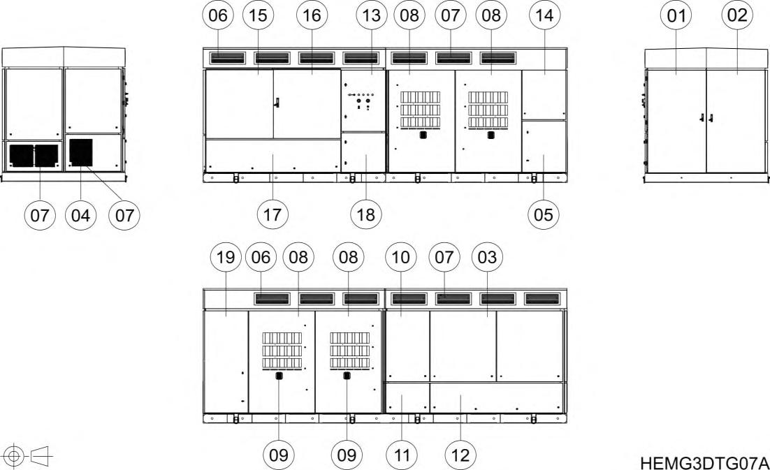
Number in figure Cabinet
1, 2, 14, 19 MV Switchgear cabinet
15 – 17 DC cabinet 2
Detail
1: Access door to MV switchgear.
2, 19: Access door to MV AC cables installation.
14: Econ Mode (optional).
15, 16: DC cabinet access doors. DC current measurement and protections: input fuses, insulation monitor, DC surge arrester and DC switch disconnectors. DC manual disconnectors are optional.
17: Access covers for DC wiring connection.
3 Inverter cabinet 3: Access door to removable power stages (FRUs).
4 AASS transformer 4: Auxiliary services (AASS) transformer.
5 Protections and measurements Ventilation protections. MV measurements.
6, 7 Ventilation grids
8,9 Cooling cabinet
10, 11, 12 LC filter cabinet
13 Main control cabinet
6: Air inlets for the cooling system.
7: Air outlets for the cooling system.
8: Air inlets for the cyclone system and dust particles outlet. Access door for the cyclone filter and impulsion fan. MV transformer access cover.
9: Dust particles outlet.
10: C filter access cover, RFI board
11: AC surge arrester, AASS fuses.
12: Main inductance access cover.
13: Controls for user local control, central control board and communication devices (Ethernet switch).
18 User cabinets 18: User cabinet1
1 Configuration will vary depending on the customizable options chosen by the customer.
2 Varies according to the number of DC inputs.

ISOLATION GUIDELINES

To guarantee the safety of the personnel who will work on the inverter, it is essential to open the input circuit breaker and ground the MV switchgear that provides supply to the equipment. Besides this, customer must remove voltage from the MV facility network switchgear and discharge it to ground by keeping it in ground position while the equipment is open (unless a task specific H&S study is completed, and task specific procedure is available). See numbers 1 and 2 in the figure above.
Additionally, it is necessary to fully disconnect the DC supply from the photovoltaic field to the equipment (number 3 in the figure above) (unless a task specific H&S study is completed, and task specific procedure is available). It can also be disconnected by opening the DC circuit breakers – from the DC cabinet (number 4 in the figure). In this case, please notice the DC cabinet cannot be opened as there is voltage present from the photovoltaic field.
To carry out any maintenance or activity inside the inverter, user must verify there is no voltage presence in the equipment, as well as to carry out the LOTO procedure as stated in section “Safe stop of HEM” Always apply the five golden rules to ensure there are no hazardous voltages.
These maneuvers are out of the scope of Power Electronics’ staff. Customer will be responsible to guarantee the safety or Power Electronics personnel who intervenes in the equipment.

WARNING

Before opening the cover to access the highlighted cabinet, always ensure the inverter is fully isolated from the medium voltage network and LOTO procedure has been followed.

Avoid standing in front of the transformer covers.

WARNING
GROUND CONNECTION
Electric shock prevention:
The inverter chassis must be properly grounded to prevent a possible electric shock if a leakage current flows through the enclosure. Disconnect all the voltage supplies before proceeding with maintenance operations within the equipment. The inverter contains capacitors which may have a hazardous voltage even when the input voltage is disconnected. Make sure inverter is discharged before performing any operation
Only connect the earth grounding to the inverter earth plate. Do not use the case or the chassis screw for grounding.
The earth protection cable must be connected first and disconnected last on maintenance actions.
The HEM inverter must be connected to earth. Refer to Hardware Manual for earth plates connections inside the HEM.
AC output cables are medium voltage cables. As shown in the figure below, they are coaxial cables, each one including earth. To carry out a correct connection, it is necessary to bond the earth of each phase and connect it to the ground busbar of the equipment (located in the MV voltage switchgear).


Required qualification to perform maintenance tasks on HEM inverters
There are different maintenance types (A, B, C). The qualification required to carry them out is detailed in the Customer Maintenance Training Plan documents
In all cases, official maintenance reports must be filled in and sent to Power Electronics; the warranty of the equipment can be conditioned to the delivery in time of such reports. Click on the link to access the reports

NOTICE
Official maintenance reports must be filled in and sent to the email address of the correspondent delegation. Consult Power Electronics to get the last updated information. The warranty of the equipment can be conditioned to the delivery in time and format of the maintenance reports.
The personnel approval is subject to Power Electronics training and acceptance. After the approval, technicians get a certificate that enables them to perform advanced maintenance tasks for one year. After this time span, the certification is automatically in force again, if the use of it is clearly justified (through enough performed maintenance routines). In case of no use or insufficient use of this certification, it will be necessary to renovate the approval, which may be subject to additional training.

SAFE STOP AND START UP
HEM Statuses
Before detailing these procedures, it is convenient to define three possible statuses to carry out the tasks of maintenance. These statuses are attached to every maintenance action groups. Wear always the PPE according to electric risk and to the current H&S regulations.
STATUS 1
STATUS 2
STATUS 3
HEM STATUSES
Proper status for carrying the power revision.
Inverter running (no action required from “Safe stop of HEM”).
Check points for absence of voltage: No measuring in Status 1.
Proper status for carrying the revision with auxiliary and AC voltage.
Voltage cannot be checked in Status 2, as the equipment is powered up.
Proper status for carrying the dead revision.
Inverter completely stopped, isolated, discharged, and grounded Follow the complete process from section “Safe stop of HEM”
Make sure MV Switchgear is opened and earthed/locked.
Make sure there is no independent auxiliary supply coming from outside the inverter.
Make sure there is no live voltage neither in DC PV field boxes nor in the AC facility network (customer’s responsibility).
If there is any connection to the Bus Plus cabinet, make ensure it is OFF, locked, insulated, and grounded
Afterwards, wait for the discharge of the internal capacitors of the equipment.
The absence of voltage must be verified once an equipment has been isolated. Refer to section “Check points for absence of voltage” for further information.
Safe maneuvers for ORMAZABAL MV Switchgear
The sequence for stopping and isolating the HEM for the maintenance tasks depends on the model of the installed MV switchgear.
For carrying out some of the maintenance tasks, it is necessary to stop the station in safe conditions and generate a safe scenario to perform the tasks. Make sure the inverter is properly stopped and locked before stopping and locking the main transformer and DC PV field. In order to perform this task, make sure that there is no independent auxiliary supply coming from the outside of the inverter. Also, make sure there is no live voltage neither in DC PV field nor in the MV AC facility network.
After these actions, the installation must be set on service back again.
In thefollowing point the procedure to stop the HEM inverter from aMV Ormazabal switchgear is detailed.
The main parts of the front side of the MV switchgear are described in the following picture:
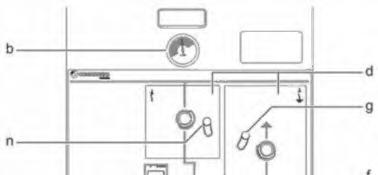
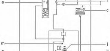

PARTS OF ORMAZABAL MV SWITCHGEAR
b Manometer window
c ekorVPIS or ekorIVDS voltage indicator
d Operation area:
GREY: Disconnector / switch-disconnector
YELLOW: Earthing switch
e ekorRPG protection unit
f State indicators
g Padlocking with interlock of the earthing system
j Spring charging indicator
k Manual spring charging circuit breaker
l Cable cover unlocking
m Operation counter
n Interlock in disconnector / switch-disconnector
o Circuit breaker operation area
RED: Opening push-button
GREEN: Closing push-button
Earthing system
In ORMAZABAL MV switchgears, it is extremely important to perform the earth connection following the next procedure, to avoid a break in the seal gasket at the door frame:
The earth connection is carried out by using an opening tool. This tool is introduced in the interlock of the earthing system, marked in the following picture:
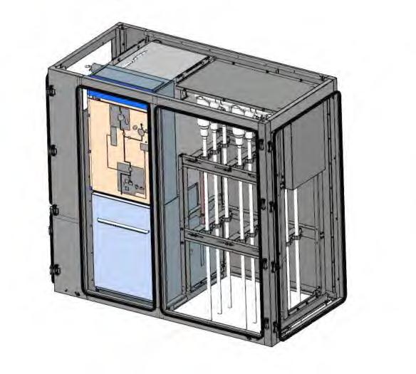
It is necessary to make the maneuver so that the rod of the opening tool is inside the frame. The rod is movable, so it must be sufficiently shifted to the inner part so that it does not pass over the seal.
The following pictures show which is the proper maneuver:

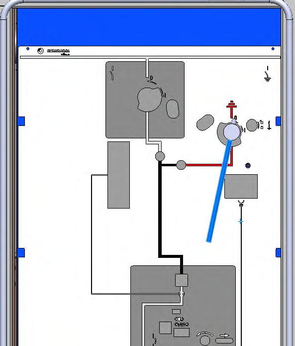
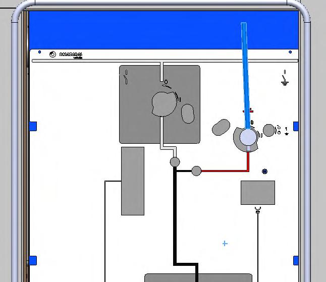


Avoid performing the opening in such a way that the joint interferes with the rotation of the tool.

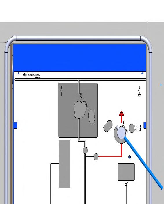


CAUTION
It is extremely important to follow this instruction to connect the switchgear earth system so that a break in the seal gasket at the door frame is avoided.
Safe stop of HEM
To carry out the maintenance tasks, it is necessary to stop the inverter correctly and guarantee safety conditions. The inverter safe stop sequence to get a safe scenario it is as follows

NOTICE
If the equipment is connected to any external Freemaq DC/DC for connection to a storage system, please stop and isolate all DC/DC before starting the following procedure
SAFE STOP OF THE INVERTER
1. Depending on the configuration stablished, the equipment can be stopped in the following ways (depending on an internal configuration of the equipment):
- On / off key to the off position and removing it
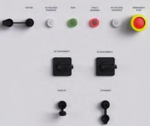

- Remotely It is possible to stop the equipment through the parameter ‘G2.6.1.1- General Selector’ configured as ‘Off’.
- On / off key or remotely. It is possible to stop the equipment with the on / off key or through the parameter ‘G2.6.1.1- General Selector’ configured as ‘Off’.
Note: For these three options parameters ‘G2 6 1 2-DC Virtual Sel conf’ and ‘G2 6 1 3-AC Virtual Sel conf’ must be set to 'Selector'.
At this moment internally the equipment is programmed to open the MV switchgear after 40 min.
2. Check locally that the run LED is off.

SAFE STOP OF THE INVERTER
3. Check remotely, through the software or display that the active and reactive power and current, both at the output of the equipment and in the power stages (DC bus), are zero.

4. Open and padlock the disconnectors of the customer string boxes.
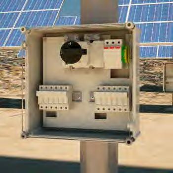
Note: It is responsibility of the customer to carry out manoeuvres at the DC facility network (string boxes) to guarantee a safe scenario.
5. In case the inverter is equipped with the Bus Plus option (Basic or Advanced), it is always necessary to make the DC/DC safe stop and LOTO before measuring the DC voltage in the plates of the DC cabinet.

SAFE STOP OF THE INVERTER
6. At the end of the 40 minutes, the MV switchgear opens. It is important to respect this time and not to access the medium voltage part of the equipment before.
Note: The MV transformer temperatures can be checked in parameters ‘SV1 6 8 - MV PT100 (1)‘, SV1.6.8 - MV PT100 (2)‘, SV1 6 8 - MV PT100 (3)‘ to see that they have decreased
7. Wait for 5 minutes to ensure that the de-energization of the DC bus has been carried out.
Note: In case of not having Econ Mode option and there is no auxiliary power supply to carry out the active discharge of the DC bus, the auxiliary services must be supplied externally to carry out this discharge or this purpose, the inverter has two terminals to supply the auxiliary services
8. Access to Power Comms and check the DC bus discharge.

9. Set firstly the AC LOTO selector and then the DC LOTO selector to the open position and lock them with a padlock. ,
Note: In case of not having Econ Mode option and there is no auxiliary power supply to carry out the active discharge of the DC bus, the auxiliary services must be supplied externally to carry out this discharge or this purpose, the inverter has two terminals to supply the auxiliary services.

SAFE STOP OF THE INVERTER
10. If the optional DC manual disconnectors are available, open the manual disconnectors of the DC cabinet and padlock to lock.


11. Open MV switchgear cabinet. The following steps must be performed:
1. Open manually the disconnector of the MV switchgear.
2. Remove the padlock that prevents manual closing of the MV switchgear and closing of the MV switchgear circuit breaker pressing the green push-button. Notice that step 1 must be performed.
3. Ground the MV switchgear.
4. Padlock the MV switchgear to lock. Step 1

Note: Check the pressure of SF6 is sufficient to operate in the MV switchgear.
SAFE STOP OF THE INVERTER
12. In case the equipment is equipped with Econ Mode, open auxiliary power supply of the Econ Mode transformer (S11+Q24) and the MV measuring board (S12) and lock them with a padlock.
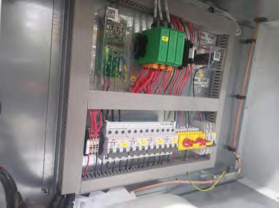

CAUTION
Note that in this moment there are permanently energized elements: in Q24, S12 and S11 (if the equipment includes the Econ Mode option). To de-energize these elements, it is necessary to disconnect the MV facility network of the client.

13. Ensure the inverter is fully isolated. Disconnection: the MV voltage at the AC terminals at the inverter input, as well as any auxiliary power supply, disappears at this time. This must be checked by measuring at the verification points.
- Make sure MV switchgear is opened and earthed / locked.
- Make sure there is no independent auxiliary supply coming from outside the inverter.
- Make sure there is no live voltage neither in PV field nor in the AC facility network (customer responsibility).
Note: There is still voltage present in the lift cabinet unless there is no live voltage in the AC facility network (customer responsibility) even if the MV Switchgear is opened Refer to “Safety Instructions” for further details.
It is responsibility of the customer to carry out manoeuvres at the MV facility network and on the DC PV field boxes to guarantee a safe scenario for maintenance and operation routines inside HEM. With these last customer actions status 3 is reached on HEM.

CAUTION
Auxiliary supply must be disconnected last and connected first when possible.
If the auxiliary equipment is powered from a circuit external to the installation for any particular reason, this external circuit must be isolated at the same time as point Safe Stop of HEM is carried out.


Electric shock hazard. Auxiliary supply power layout is a characteristic of each plant and may vary from one installation to another. Check the latest electrical schematics of the plant and make sure no voltage is present by confirming with a multimeter
Electric shock hazard. Wait until all capacitors of LC filter, every FRU and auxiliary power supply circuit of the inverter are discharged under 30 V. Check it with a multimeter.

CAUTION
Before any maintenance operation, verify that the equipment is completely stopped before maneuvering any cutting element. This applies to elements with load-breaking capacity (circuit breakers and switch disconnectors) as well as those with no capacity (disconnectors). Under no circumstances any of these components must be manually operated when the inverter is energized.
This warning involves any element located at the PV field (e.g. combiner box).
Check points for absence of voltage

CAUTION
The absence of voltage must be verified once an equipment has been isolated, with the necessary means and PPE.
In addition, the inverter specific diagrams of the installation should be reviewed.
Even the multimeters have scheduled revisions, it is convenient always to check the multimeter is working fine before to do measures, especially to prove dead. This might be damaged and show false values. Use a commercial proving unit to check it.
Use appropriate equipment for DC power measures (up to 1500 Vdc).
It is responsibility of the technical personnel to have their tools calibrated and in good conditions.

NOTICE
This symbol means no tool is required for the maintenance task.
STATUS 1
No measuring in Status 1.
STATUS 2
There is no absence of voltage checking in status 2.
STATUS 3
1. Ensure the correct operation of the multimeter.
2. Wear the appropriate PPE based on the electrical arc studies of the plant and the risk assessment carried out by the customer.
STATUS 3
3. Check the absence of DC voltage from the PV field. For this, measure at the input plates located at the lower part of the DC cabinet.

CAUTION
For this measurement, the string boxes must be disconnected, and the DC bus discharge must be checked via Power Comms. Consult “Safe stop of HEM” section for this procedure.
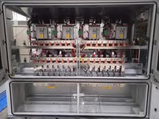
Note: In case the inverter is equipped with the Bus Plus option (Basic or Advanced), it is always necessary to make the DC/DC LOTO before measuring the DC voltage in the plates of the DC cabinet
4. Check for absence of voltage on the main AC power busbar, measuring on terminals of the F100 disconnectable fuse holder base.

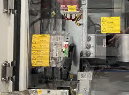
STATUS 3
5. Check that the internal capacitor bus of the power stages has been discharged. For this, make a measurement at the DC busbar of each power stage. It is recommended to use long leads to perform this measure.
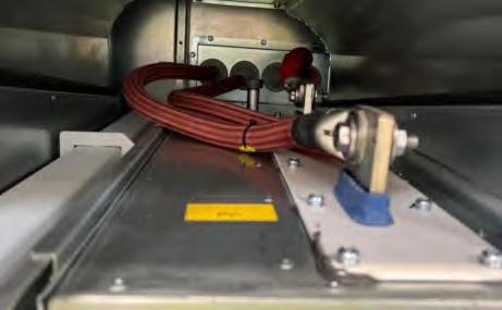
6. Check that there is no voltage on the LC filter by measuring on the LC filter contactors.
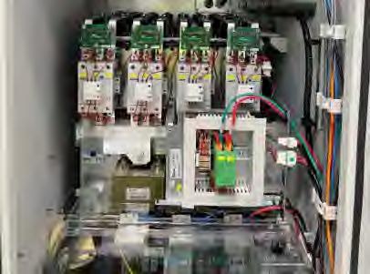

Note: It is recommended to perform the measurement with the measuring equipment set to both AC and DC.
7. Check the absence of voltage in the econ mode auxiliary transformer by measuring at the MV control cabinet S11 and S12 disconnectors.
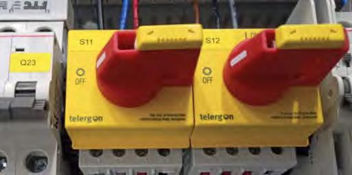
STATUS 3
8. Check the capacitors of the 120 VDC auxiliary power supply are discharged in the following measuring points:
Main control cabinet:
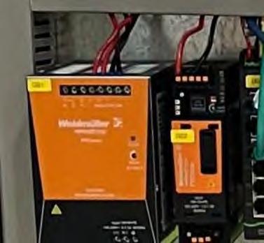

Protections and measurements cabinet:

9. Short-circuit DC cabinet and ground as shown in the following pictures.
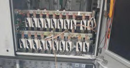

If the equipment is equipped with the Bus Plus Basic or Advanced option, each of the independent inputs of the PV field must be short-circuited. The following is an example of an equipment with a one input:
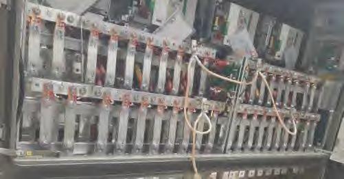

Note: In case the door of the DC cabinet cannot be left open (due to environmental conditions) it must be connected to the metal structure at the top of the DC cabinet.
Safe start up for HEM
To carry out the safe start up on the inverter, follow the steps of safe stop reconnecting the elements on reverse sequence as detailed above.
SAFE START UP OF THE INVERTER
1. Remove the ground short-circuit DC cabinet.
2. In case the DC manual disconnectors (optional) of the DC cabinet are available, close them.
3. Remove the padlock and close the auxiliary power supply of the Econ Mode transformer and MV measurement board.
4. Remove the padlock from the MV switchgear to disconnect the equipment from ground.
5. Open the circuit breaker of the MV switchgear.
6. Set the padlock that prevents manual closing of the MV switchgear.
7. Close the MV switchgear disconnector.
8. Close all equipment doors.
9. Remove the padlock and close the disconnecting devices from all string boxes.
10. Remove the padlock and turn the DC LOTO selector to close position.
11. Remove the padlock and turn the AC LOTO selector to close position.
12. Depending on the configuration stablished, the equipment can be started up in the following ways (depending on an internal configuration of the equipment):
On / off key to the on position and removing it.
Remotely. It is possible to stop the equipment through the parameter G2.6.1.1- General Selector’configuredas‘On’.
On / off key and remotely. It is possible to stop the equipment with the on / off key or throughtheparameter‘G2.6.1.1- GeneralSelector’configuredas‘On’.
Note: for all options parameters‘G2.6.1.2-DCVirtualSelconf’and‘G2.6.1.3-AC Virtual Sel conf’mustbesetto'Selector'.

SIX-MONTHLY MAINTENANCE
Actions to carry out every 6 months.
The global operation time of the six-monthly maintenance is shown below. The maintenance tasks should be carried out by two technicians (the time shown in the table is calculated assuming that two technicians are performing the tasks).
MAINTENANCE
Checklist
Actions to carry out every 6 months. These tasks should be carried out by two technicians (so the time shown below is assuming two technicians are performing the tasks).
These next tasks can be carried out with the station running. Do not remove the covers and open the doors, as power is present inside. These values can be checked externally with the display or with a PC.
Remotely: By means of a PC and PowerMonitoring.
On site: By means of the display. Power Electronics supplies a display to visualize the data of the different parameters. User must simply connect it to the corresponding port at the main control cabinet (cabinet num.9), and then the parameters will be displayed on screen.
1 SPDs (Surge protection devices) feedback
2 GFDI (Ground fault defect interrupter) feedback.
3 Signalling elements. LEDs and display work
4 Main temperatures in range
5 Checking the vibration of the fans
Power revision (Inverter in status 1)
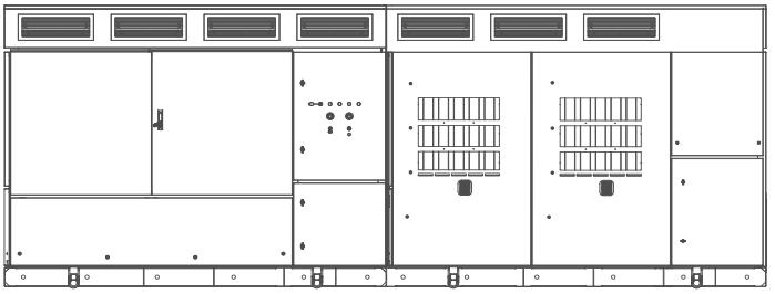
1. SPDs feedback
SPD (Surge protection devices), both AC and DC, feedbacks are registered and not blown. To test it, check the following software parameters. The purpose of the checking is not to operate on the components, as in status 1 doors cannot be opened.
DC SPD
Check bit 10 (from up left to right) in the parameter [SV7.2.1.11-Warn.161 to 176] that the warning [W170:Overvoltage DC] is not enable (X) as shown in the following image. When the parameter is accessed, the following drop-down is enabled: Refer to the Software and programming Manual for further information
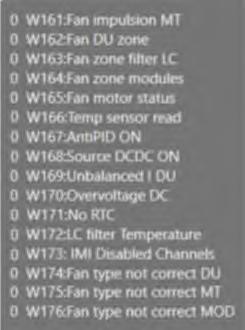
AC SPD
Check bit 10 (from up left to right) in the parameter [SV7.2.1.2-Warn.17 to 32] that warning [W26:Overvoltage AC] is not enable (X) as shown in the following image. Refer to the Software and programming Manual for further information.
2. GFDI feedback
Check software feedback of GFDI (Ground Fault Detector Interrupter) if present. To test it, check software parameters of the feedback value of the component. The purpose of the checking is not to operate on the component, as in status 1 doors cannot be opened.
3. Signalling elements. LEDs and display work
Check the LEDs on the inverter are not defective. Connect the display to the external port to check it is operative.
4. Main temperatures in range
Check internal main maximum temperatures after 120 minutes on full/high power. Register the values. Check general maximum values. If values are over 100ºC for IGBTs and over 50ºC at any module, check every cabinet with temperature parameters for every module value. Register the values.UsePowerElectronics’softwaretoolPowerMonitoring when possible.

5. Checking the vibration of the fans
Check that fans of the equipment exhibit normal and continuous operating noise.

ANNUAL MAINTENANCE
Remember to carry out the six-monthly maintenance.
The global operation time of the annual maintenance is shown below. The maintenance tasks should be carried out by two technicians (the time shown in the table is calculated assuming that two technicians are performing the tasks).
MAINTENANCE
GLOBAL OPERATION TIME
Checklist
The following task can be undertaken with the inverter running. Do not remove the covers and open the doors, as power is present inside. As in the six-monthly maintenance, there are two ways to check the values, remotely through PowerMonitoring or on site using a display.
1 Previously performed maintenance tasks (see tasks list in “Six-monthly maintenance” section)
2
These tasks must be done with equipment completely “dead “(no voltage at all, stopped, discharged isolated and locked).
4 Cleaning of the cabinet and checking of the hot spots in the AASS transformer
5 Checking of the AC and DC RFI filter.
6 Checking of the C filter capacitor discharge boards.
17 Checking of the cyclone filter
18 Cleaning of the ventilation ducts and heat exchanger.

CAUTION
Annual maintenance tasks must only be performed by qualified personnel and approved by Power Electronics.
Otherwise, the equipment may get damaged, and personnel could suffer severe injuries.
Power revision (Inverter in status 1)
1. Previously performed maintenance tasks
Verify six- monthly maintenance has been properly carried out in a previous stage.
2. DC sources in proper range

Check voltages of output DC control sources, voltages around +/- 1% of 24 V on [SV1.1.5-Power Source] software parameter The purpose of the checking is not to measure on the component itself, as in status 1 doors cannot be opened. Quantity of DC sources might vary depending on customer’s configuration
Dead revision (Inverter in status 3)
1. Checking of the hot spots and plastic elements in the DC cabinet

Visually inspect the DC cabinet to ensure that there are no hot spots. Check that the plastic elements of the cabinet are in good condition and have not been damaged, as well as the condition of the sealing of the wall bushings between the cabinets. An example is shown below:
Correct status
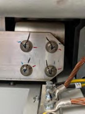
Not correct status
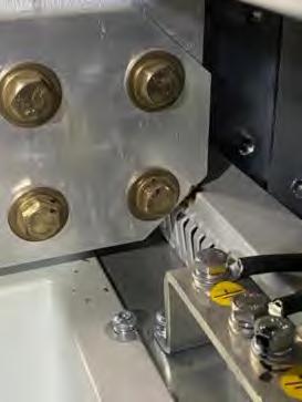
2. Checking of the hot spots and plastic elements in the inverter cabinet
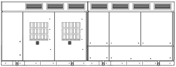
Visually inspect the inverter cabinet to ensure that there are no hot spots. Check that the plastic elements of the cabinet are in good condition and have not been damaged, as well as the condition of the sealing of the wall bushings between the cabinets An example is shown below:

3. Checking of the hot spots and plastic elements in the LC filter cabinet

Visually inspect internally the LC filter cabinet to ensure that there are no hot spots. Check that the plastic elements of the cabinet are in good condition and have not been damaged, as well as the condition of the sealing of the wall bushings between the cabinets.
4. Cleaning of the cabinet and checking of the hot spots in the AASS transformer

Visually check the AASS transformer. Cleanness, connections tightened and no overheating signs. Check that the cabinet does not have any impact or oxidation signs and other marks due to climate effects.
Visually inspect the AASS transformer to ensure that there are no hot spots. Check that the plastic elements of the cabinet are in good condition and have not been damaged, especially those designed for the proper sealing of the equipment. An example is shown below:
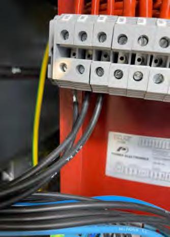
5. Checking of the AC and DC RFI filter

Visually inspect the AC and DC RFI filter to ensure they are in good condition Cleanness, connections tightened and no overheating signs.
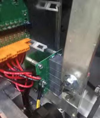


6. Checking of the C filter capacitor discharge boards

Visually inspect the C filter capacitor board to ensure they are in good condition Check that the cabinet does not have any impact or oxidation signs and other marks due to climate effects. Cleanness, connections tightened and no overheating signs. Do not disassemble them unless there is a visual defect.


7. Visual checking of the control panel
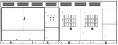
Visually inspect the control panel to ensure it is in good condition, has not been damaged and there are no visual signs of overheating. Check that the cabinet does not have any impact or oxidation signs and other marks due to climate effects.
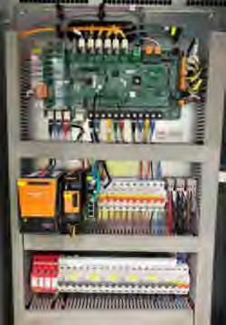
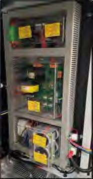
8. Visual checking of the user panel

Visually inspect the user panel to ensure it is in good condition and has not been damaged and there are no visual signs of overheating. Check that the cabinet does not have any impact or oxidation signs and other marks due to climate effects.
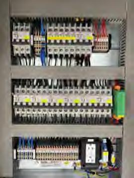
9. MV switchgear and cylinders testing

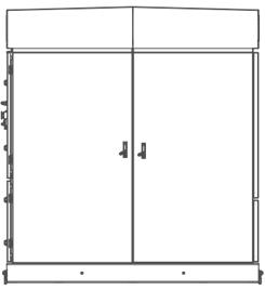
Visually inspect the MV switchgear and cylinders to ensure they have not been overheated and that the ground wires are properly connected. Check that the insulators are not damaged. Check that the cabinet does not have any impact or oxidation signs and other marks due to climate effects.
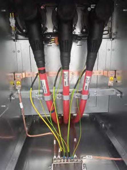
10.Checking of the MV transformer

Visually check the MV transformer. Cleanness, connections tightened and no overheating signs. Check that the cabinet does not have any impact or oxidation signs and other marks due to climate effects.
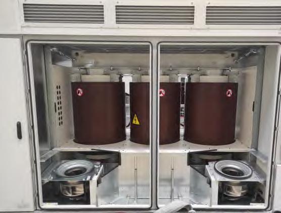
11.Checking of the enclosure
Visually check the enclosure does not have any impact or oxidation signs and other marks due to climate effects.
Clean the equipment externally. Avoid the use of solvents or soaps that may damage the painting, use only water with low lime content and neutral soaps. Avoid using pressure water devices. A vacuum cleaner can be used to clean the different cabinets.
Please, follow Health & Safety procedures for work at height, if necessary.

12.Checking of the quadruple inductance of the L filter

Visually inspect the quadruple inductance of the L filter to ensure cleanness, that connections are tightened and that there are no overheating signs. Do not disassemble it unless there is a visual defect.
Check that the cabinet does not have any impact or oxidation signs and other marks due to climate effects.

13.Cleaning of the dust filters, ventilation grids and sand traps

Visually check the cleanness of the dust filters, ventilation grids and sand traps Check the condition of the grill at the top of the MW transformer cabinet. Verify that they are in good condition and not clogged; clean them if they are dirty. If the inverter has the option of Bus Plus cabinet, clean and check the air inlets and outlets of the equipment. No replacement necessary unless filter is obviously dirty. This task should be carried out more frequently when environmental conditions require it. If in doubt of the proper frequency, please, contact Power Electronics.


CAUTION
This task should be carried out annually. However, it should be done more frequently if environmental conditions require so.
Also, in installations with a high level of contamination, it may be necessary to carry out this task more frequently. The review criteria are the following: Whenever pruning, mowing, grazing or similar tasks are carried out in the vicinity of the equipment, which may produce the presence of plant or animal debris suspended in the air.
When, due to human activities, climatic or biological reasons, the presence of solid remains in the air susceptible to accumulate on the filters is detected in the area. In this case, it will be enough to inspect the equipment that due to their location have been more exposed, and if dirt is detected in them, the inspection will be generalized to the rest of the equipment at the plant.
It will be necessary to clean the filters before the summer, and during this period to perform a remote, bimonthly, predictive maintenance of the temperatures of the stages, to verify that these are kept within the established operating limits for each type of IGBT.
14.Cleaning of the equipment cabinets and checking of the sealing the of cabinet doors
Visually check the equipment cabinet doors are sealed, the door locks work properly, and all the keys are on the locks. Check hinges, foams, keys, doors and locks.
Foams, doors, locks and hinges

Keys and handles are present.
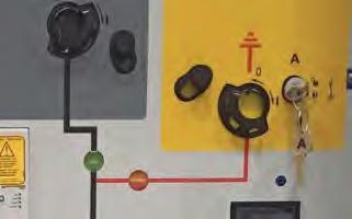
15.Cleaning of the cooling cabinet

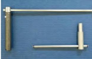

Visually check the cooling cabinet. Cleanness, connections tightened and no overheating signs. Check that the fibers have not shifted and allow airflow through the transformer windings.
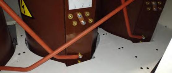
16.Checking the sealing of cyclone fans


Check that the cyclone fans are in good visual condition and properly sealed. Replace in case of damage.

17.Checking of the
cyclone
filter


Visually check the filter of the cyclone. Clean it and check that there are no dust traces in the inside. This task should be carried out more frequently when environmental conditions require it. If in doubt of the proper frequency, please, contact Power Electronics.
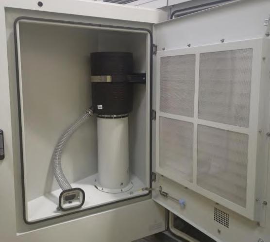
18.Cleaning of the ventilation ducts and heat exchanger

Visually check the cleaning of the ventilation ducts and heat exchanger. Verify that they are in good condition and not clogged; clean them if they are dirty.
Ventilation ducts and heat exchanger


BIANNUAL MAINTENANCE
Remember to carry out the six-monthly and annual maintenance
The global operation time of the biannual maintenance is shown below. The maintenance tasks should be carried out by two technicians (the time shown in the table is calculated assuming that two technicians are performing the tasks).
MAINTENANCE
GLOBAL OPERATION TIME
Checklist
The next tasks can be carried out with the with auxiliary and AC voltage and using adequate PPE.
STOPPED REVISION (STATUS 2)
1 Checking of the transformation ratio in the AASS and MV transformer 5 min
OK
These tasks must be done with equipment completely “dead “(no voltage at all, stopped, discharged isolated and locked).
DEAD REVISION (STATUS 3)
1 Previously performed maintenance tasks (see task list in “Annual maintenance” section)
2 Thermography of the DC cabinet.
3 Thermography of the power stages connections.
4 Thermography of the circuit breakers and inductances.
5 Cleaning and maintenance of DC switch disconnectors
6 LC filter capacitance.
min
7 Tightening torque check of the connection cables to the power stages and inductors. 30 min
8 Tightening torque check of the DC circuit breakers connection cables and busbars
9 Tightening torque check of AC circuit breaker and busbars.
10 Checking of the magnetothermal protections of the power supply of power stages and central control.
11 Checking of the tightening torques of the MV switchgear and transformer wiring.
12 Cleaning of Econ Mode transformer
13 Power stages inspection and cleaning the radiators
14 Lubrication of hinges
min
OK
min
The following task can be undertaken with the inverter running. Do not remove the covers and open the doors, as power is present inside.
POWER REVISION (STATUS 1)
1 Checking of the emergency stop button.
OK
Note: The thermography will be performed with the inverter at high or maximum load (higher than 90%) for 100 min. It is then stopped and isolated, at which point the thermography can be performed. Review inverter statuses in “Safe and stop and start up” section.

NOTICE
Please note that thermography tasks can be replaced, when not possible, by thermal labelling and visual check for signs of over-temperature.

CAUTION
Biannual maintenance tasks must only be performed by qualified personnel and approved by Power Electronics. Otherwise, the equipment may get damaged, and personnel could suffer severe injuries.
Stopped revision (Inverter in status 2)
1. Checking of the transformation ratio in the AASS and MV transformer
Check the transformation ratio in the AASS and MV transformer is within the permissible limits in [SV3.2.1-Grid voltage RS LV], [SV3.2.2-Grid voltage ST LV] and [SV3.2.3-Grid voltage TR LV] parameters
Dead revision (Inverter in status 3)
1. Previously performed maintenance tasks
Verify annual maintenance has been properly carried out in a previous stage.
2. Thermography of the DC cabinet
Check balanced temperatures in the DC cabinet. Thermography helps to detect unbalanced hot spots on phases/devices. Previously, the inverter must be at least 100 minutes at high/full power (90% average or more), then stop it and isolate it. Make sure all modules have been running during pushing time.
3.
Thermography
of the power stages connections
Check balanced temperatures in the power stages connections. Thermography helps to detect unbalanced hot spots on phases/devices. Previously, the inverter must be at least 100 minutes at high/full power (90% average or more), then stop it and isolate it. Make sure all modules have been running during pushing time.
4. Thermography of inductances
Check balanced temperatures in the inductances. Thermography helps to detect unbalanced hot spots on phases/devices. Previously, the inverter must be at least 100 minutes at high/full power (90% average or more), then stop it and isolate it. Make sure all modules have been running during pushing time.

NOTICE
Please note that thermography tasks can be replaced, when not possible, by thermal labelling and visual check for signs of over-temperature.
5. Cleaning and maintenance of DC switch disconnectors

Visually check the DC switch disconnectors. Cleanness, connections tightened and no overheating signs. Do not disassemble them unless there is a visual defect.
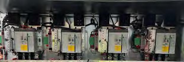
6. LC filter capacitance

Check the value of LC filter capacitance per phase is balanced (12 measures marked in the following picture). Use the multimeter in capacitance mode and make sure the bus is completely discharged. This measure should be 180 (±5%) µF.
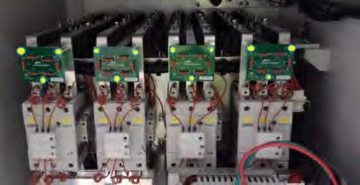
7. Tightening torque check of the connection cables to the power stages and inductors

Check the connection cables to the power stages and inductors are in good condition and bolts are properly marked. There are no visual signs of overheating. Re-tighten only, if necessary, when the factory marksare not in place. For the small screws that do not havemarks, the good electrical practice will determine if a screw is loose. Refer to the recommended tightening torque for mechanical and electrical connections in the " Torque and screw sizing" section.
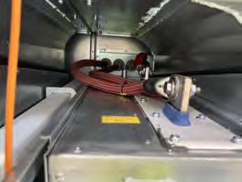
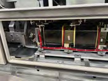
8. Tightening torque check of the DC switch disconnectors, cables and busbars

Check that the DC circuit breakers connection cables and busbars are in good condition and bolts are properly marked. There are no visual signs of overheating. Re-tighten only, if necessary, when the factory marks are not in place. For the small screws that do not have marks, the good electrical practice will determine if a screw is loose.
Refer to the recommended tightening torque formechanical and electrical connectionsin the " Torque and screw sizing" section.
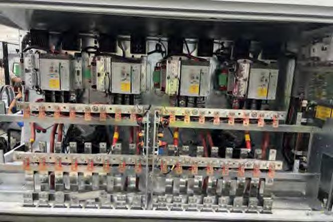
9. Tightening torque check of AC busbars

Check that the AC circuit breaker and busbars are in good condition and bolts are properly marked. There are no visual signs of overheating. Re-tighten only, if necessary, when the factory marks are not in place. For the small screws that do not have marks, the good electrical practice will determine if a screw is loose.
Refer to the recommended tightening torque formechanical and electrical connectionsin the " Torque and screw sizing" section.
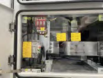
10.Checking of the magnetothermal protections of the power supply of power stages and central control

Check that the magnetothermal protections of the power supply of power stages and central control are in good condition. There are no visual signs of overheating.
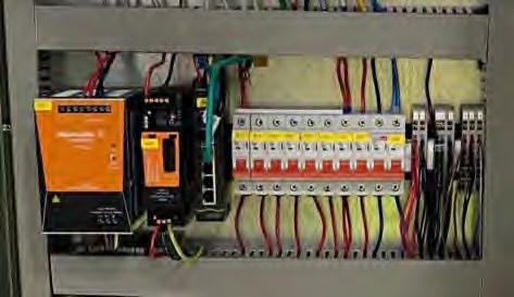
11.Checking of the tightening torques of the MV switchgear and MV transformer wiring


Check that the MV switchgear and transformer wiring are in good condition and bolts are properly marked. There areno visual signs of overheating. Re-tighten only, if necessary, when the factory marks are not in place. For the small screws that do not have marks, the good electrical practice will determine if a screw is loose.
Refer to the recommended tightening torque for mechanical and electrical connections in the " Torque and screw sizing" section.

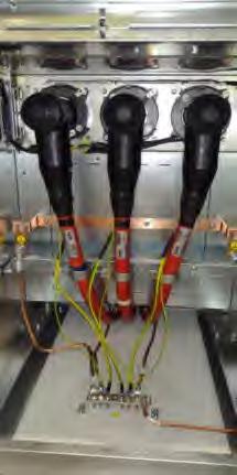
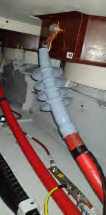
12.Cleaning of Econ Mode transformer

Check the Econ Mode transformer do not have any dust, humidity, oxidation or animal presence signs.
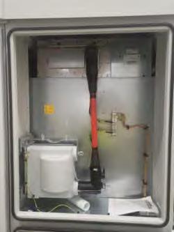

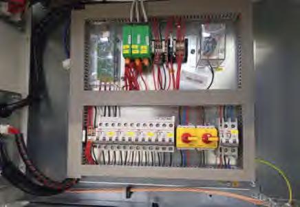
WARNING
Before opening the Econ Mode cabinet, it is necessary to disconnect the MV facility network of the customer.
13.Cleaning of the radiators and power stages inspection

Visually check the cleaning of the radiators Verify that they are in good condition and not clogged; clean them if they are dirty.
Radiators
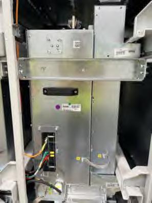

Perform a visual inspection of connectors and screws of the power stages Cleanness, connections tightened and no overheating signs. Verify that screwing marks match and that all connections are in good condition.
Power stages
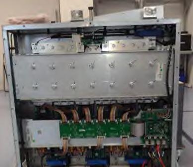

14.Lubrication of hinges
Lubricate the hinges of all the equipment access doors.
Power revision (Inverter in status 1)
1. Checking of the emergency stop button

Check the emergency stop button is not defective. After the maintenance tasks, start the equipment and trigger an emergency stop by pressing the emergency button. The fault [F43: Emergency stop] will appear, it will open the DC switch disconnectors and the MV switchgear.
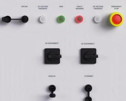

CAUTION
This task must be carried out after the maintenance tasks are completed and with the equipment running to cause an emergency stop.

FOUR-YEARLY MAINTENANCE
Remember to carry out the six-monthly, annual and biannual maintenance.
The global operation time of the four-yearly maintenance is shown below. The maintenance tasks should be carried out by two technicians (the time shown in the table is calculated assuming that two technicians are performing the tasks).
MAINTENANCE
GLOBAL OPERATION TIME 2 h 27 min
Checklist
These next tasks can be carried out with the station running.
POWER REVISION (STATUS 1)
1 Previously performed maintenance tasks (see task list in “Six-monthly maintenance" "Annual maintenance” and “Biannual maintenance” section). -
2 Checking of the AC current and voltage measurement of the low voltage 5 min
3 Checking of the current measurements on the LC filter capacitor banks. 3 min
4 Checking of the insulation monitoring device 3 min
The next tasks can be carried out with the with auxiliary and AC voltage.
1 Previously performed maintenance tasks (see task list in “Biannual maintenance” section)DEAD REVISION (STATUS 3)
OK
These tasks must be done with equipment completely “dead “(no voltage at all, stopped, discharged isolated and locked).
1 Previously performed maintenance tasks (see task list in “Annual maintenance” and “Biannual maintenance” section)
2 Checking of cable passage joints. 60 min
3 Checking of the thermostat on the LC filter inductances. 3 min
4 Checking of the thermostat on the AASS transformer. 3 min
5 Visual inspection of the MV switchgear, MV connection bottles and the electrical protections of the MV switchgear. 60 min
6 Checking of the manoeuvre / feedback and MV switchgear protections. 10 min

CAUTION
Four-yearly maintenance tasks must only be performed by qualified personnel and approved by Power Electronics. Otherwise, the equipment may get damaged, and personnel could suffer severe injuries.
Power revision (Inverter in status 1)
1. Previously performed maintenance tasks
Verify annual maintenance has been properly carried out in a previous stage.
2. Checking of the AC current and voltage measurement of the low voltage
Check the AC current and voltage measurement of the low voltage.

3. Checking of the current measurements on the LC filter capacitor banks
Check the current measurements on the LC filter capacitor banks
4. Checking of the insulation monitoring device
Check the insulation monitoring device is properly working

Stopped revision (Inverter in status 2)
1. Previously performed maintenance tasks
Verify biannual maintenance has been properly carried out in a previous stage.
Dead revision (Inverter in status 3)
1. Previously performed maintenance tasks
Verify biannual maintenance has been properly carried out in a previous stage.
2. Checking of cable passage joints
Check the cabling is in good visual condition and properly sealed.

3. Checking of the thermal sensor on the LC filter inductances

Check the thermal sensor on the LC filter inductances and the wiring are in good condition

4. Checking of thermal sensor on the AASS transformer

Check the thermal sensor on the AASS transformer and the wiring are in good condition.

5. Visual inspection of the MV switchgear, MV connection bottles and the electrical protections of the MV switchgear

Visually check the MV switchgear, MV connection bottles and the electrical protections of the MV switchgear are in good condition and bolts are properly marked. There are no visual signs of overheating. Re-tighten only, if necessary, when the factory marks are not in place. For the small screws that do not have marks, the good electrical practice will determine if a screw is loose.

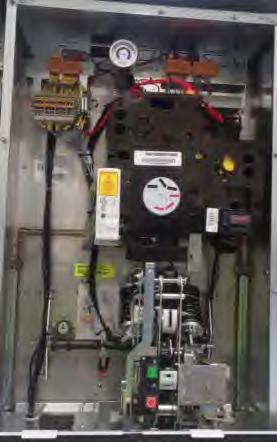
6. Checking of the maneuver/feedback and MV switchgear protections

Check that the maneuver/feedback and MV switchgear protections are in good condition and bolts are properly marked. There areno visual signs of overheating. Re-tighten only, if necessary, when the factory marks are not in place. For the small screws that do not have marks, the good electrical practice will determine if a screw is loose.
