Yield kit 3.0 Installation manual

Rev. 0 Page 1
Rev. 0 Page 2 Updates Version Date Description Issued from 0 20/02/22 First release E. Bighi

1. FieldView Yield ECU. The “brains” of the operation. This device features: 16GB of on-board storage, input for External GPS antenna, Bluetooth® connectivity for pairing with an iPad
2. External GPS receiver with EGNOS correction of the GPS signal. The GPS receiver should be mounted on the roof of the cab, on the centreline of the combine. Usage of this GPS receiver will provide better positional accuracy than just an external GPS antennae.

3. Optical Sensors
Two sensors will be installed on either side of the clean grain elevator. A light beam is sent between the two sensors, allowing for the measurement of the volume of grain on each paddle. Sensors will be wired directly to the FieldView Yield monitor through the supplied harnesses.
4. Moisture sensor
Moisture Sensor extends the FieldView Yield kit System to provide reliable grain moisture readings. The sensor installs on the base of the clean grain elevator on the lower door and takes capacitance readings from grain as it moves through the elevator. The raw data gathered from the Moisture Sensor is sent to the Yield Monitor and wirelessly uploaded to create high quality moisture maps viewable through the FieldView Cap App. Installation position on the lower door is important but varies somewhat from harvester to harvester. The key is to install close to where grain exits the cross auger and near the lowest point of the door, just ahead of where significant wear is visible from grain flow.
The FieldView Yield ECU mounts in the cab of the combine and needs to be connected to the standard 12V Auxiliary power Socket protected from 5 Amp fuse. If there is not such Auxiliary Socket, you need to use additional cable in the kit which needs to be wired into switched 12V power protected from 5 Amp fuse and after that you will be able to connect Yield ECU to it.
1. Remove any headliner panels or lights needed to access 12V switched power and create a free space to install the yield monitor. To ensure optimal Bluetooth™ connectivity, do not place the yield monitor directly next to radio interference, such as a two-way radio.

2. Use the supplied T-Splice Connectors to connect to +12V and Ground. Use pliers to snap the T-Splice Connectors onto the wires. Be sure to use the correct size connector and ensure the connector “snaps” shut.
3. With the T-Splice connectors attached to 12V switched power, attach the Red spade connector from the lead on the Primary Wiring Harness to +12V and the Black spade connector to Ground.
4. Install the bracket with preinstalled FieldView Yield ECU on it on the back site of RAM mount of iPad as it is shown on the picture 1
1. Locate a zone on the combain cab roof to attach the GPS receiver mounting plate.


2. Clean dust and debris off of the mounting zone with an adhesive cleaning wipe.
3. Attach the adhesive-tape-side of the gps receiver mounting plate to the cab roof in the cleaned zone.
4. Attach the GPS receiver to the mounting plate
5. Plug the 14-pin connector into the External GPS receiver
6. Connect extended harness of Moisture and Optical sensor
7. Connect the power plug to Auxiliary Power socket in the Cab of Combain
8. Connect the Field View Drive
9. Connect the Yield ECU
Two optical sensors are included with your Yield Monitor. The 2-wire sensor is an emitter, and the 3-wire sensor is a receiver. LED lights can be found on the body of the sensors, the green light indicates the sensors are connected to power. The sensors record the amount of grain on each paddle by measuring the amount of time the sensor light is blocked. Your FarmTRX Yield Monitor will automatically transfer these raw sensor readings to your Web App account, so you can post-calibrate all of your fields in a few simple steps online if you don’t get around to calibrating in-field while harvesting. To obtain the most accurate yield data readings, the placement of the optical sensors should meet the following criteria:
1) Sensors should be installed as high up the clean grain elevator as reasonably possible, in a place where you can access the inside and outside of the elevator, taking care to ensure they won’t contact moving parts on the combine.

2) Sensors should be centered on the paddles of the elevator chain. Some elevator chains may have brackets supporting the paddles which can interfere with the sensor beam. If this is the case, you can cheat the sensor location outwards to avoid these brackets.
Please refer to the Drilling Measurements Table on page 7 for sensor placement measurement specifications on several combine makes and models. If your combine is not found in the table, please select an appropriate sensor location based on the above two steps.


Next, you will need to measure and mark where to drill holes for the sensors on the clean grain elevator. On the upwards direction, the sensors will mount on the inside and outside face of the elevator (where filled paddles of grain pass by). The Drilling Measurements Table below displays the measurements for common combines:
If your model is not shown in the Drilling Measurements Table, remember the main principles for successful sensor installation:
1) Place sensors as high in the clean grain elevator as reasonably possible.
2) Place sensors centered on the paddles of the elevator chain. The key to achieving accurate results from your sensors is to make sure the sensors are only measuring variations in grain on top of each paddle. When measuring for the X value, take note of the brackets supporting each paddle. If the X distance places the sensor too close to the edge of the supporting bracket, or if it lines up with an angle on
the bracket, they must be moved slightly. The diagram below highlights several installation examples with the profile views of varying paddle support brackets and the best places to drill the sensor holes.

Note: At this stage, it is crucial that the elevator chain and paddles are in good shape –the chain should not be overly loose. If loose, with paddles worn down or missing, the quality and accuracy of yield readings will be negatively impacted.
1. Using measurements from the Drilling Measurements Table, measure and mark the height (Y). Measure from the center of the bearing, to height (Y), and mark. We recommend using masking tape to make marking easier. Use a framing square to trace the height (Y) across the masking tape on the clean grain elevator.


Note: It is very important that optical sensors are installed directly opposite each other, so take care when marking mounting holes. As stated above, you don’t need to follow the table measurements exactly. As long as the sensors are mounted high up on the elevator while centered on the paddles, you will receive accurate results.

2. With height (Y) and distance (X) marked, use a center punch to mark the location for drilling the sensor mount pilot holes.
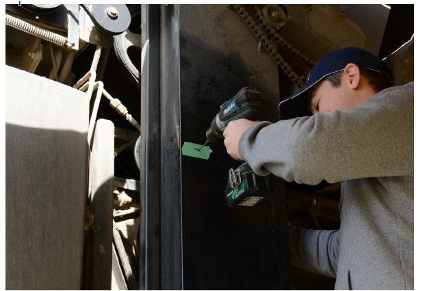


6. IMPORTANT: Use an alcohol swab to thoroughly clean the area around the drilled hole, ensuring that all oil, grease, and residue are completely removed from the elevator face.
Let the alcohol evaporate completely so the surface of the elevator around the drilled hole is dry.
If any oxidized paint is present on the elevator door around the drilled hole, use a household cleaning product to thoroughly clean and prep the area prior to using an alcohol swab.
Note: The Sensor Mounting Plates stick directly onto the elevator door. To ensure proper adhesion, the door must be through cleaned of all residue.


9. After ensuring the area around the drilled hole is completely clean and dry (Step 6), align the Drill Guide with the hole and press firmly against the side of the elevator for at least 15 seconds.


The adhesive bond is activated by pressure, so pushing firmly and holding with consistent pressure is crucial for creating a strong bond between the Drill Guide and the elevator.
To allow time for the adhesive bond to cure, the next step in the process will be installing the yield monitor and connecting to power, then running the wiring harness from the cab to the elevator.
11. Turn the Drill Guide counterclockwise to remove from the Mounting Plate. 12. Put the Drill Guide onto the 30 cm drill extension and put into drill.Attach the 3 mm pilot bit.
13. Insert the Drill Guide into the Mounting Plate and turn clockwise to secure in place. This will ensure straight alignment on the drill. Proceed to drill a hole into the back wall of the elevator.


14. Turn the Drill Guide counterclockwise to remove from the Mounting Plate. Remove the pilot drill bit and replace with the step drill bit.
15. Carefully align the tip of the step drill bit with the pilot hole in the back elevator wall. You will be able to feel the tip engage.
1 6. Insert the Drill Guide into the exterior Mounting Plate. Drill the step drill bit through the back wall. If necessary, deburr the back hole.
1 7. Use an alcohol swab to thoroughly clean the area around the drilled hole on the back surface of the elevator, ensuring that all oil, grease, and residue are completely removed from the elevator face. Let the alcohol evaporate completely.


18. Remove the red backing on the adhesive side of the FarmTRX Mounting Plate and insert the Drill Guide into the Mounting Plate. Turn the Drill Guide clockwise to lock into place.
19. Align the Drill Guide with the hole and press firmly against the side of the elevator, pushing consistently for 15 seconds.


20. Leave in place for one minute, then remove the Drill Guide.
21. Insert both sensors and turn clockwise to secure in place. Connect the sensors to the Wiring Harness.
1. Once the Yield ECU is mounted, the Primary Wiring Harness will need to be routed outside of the cab and towards the clean grain elevator. The Wiring Harness can exit at the base of a window if the seal allows, at an existing wiring grommet, or by drilling a new location.

2. Once the Primary Wiring Harness has been routed outside of the cab, determine a safe pathway to the clean grain elevator, avoiding any moving parts on the combine. In most cases you will want to follow the main bundle of wiring harnesses and secure the FarmTRX harness along that route.
Note: It is crucial that the Primary Wiring Harness is secured away from any moving parts or belts, anything that may cause breaks or wear.
Once the optical sensors are installed and connected to the Yield ECU, the system can be tested in the following ways:
1. Power on the harvester. This should power on the Yield ECU wired to switched 12V power.
2. To test the power: Using your smartphone or tablet, download and open the FIELDVIEW YieldKit Web App and navigate to the Connection page to search/scan for Bluetooth™ devices. A device called “YM:___” should appear under Available Devices. If it does not appear, try pressing the refresh button. If it still does not appear you may need to cycle Bluetooth™ on your phone or tablet off and on.
3. Test the optical sensors.
With the harvester powered on (the engine does not need to be running for this), go to the clean grain elevator and turn the thresher drive by hand. When the empty paddles pass by the optical sensors, the sensor with the LED lights will blink. If blinking occurs then the optical sensors are powered on correctly and in alignment.

The FieldView Moisture Sensor extends the FieldView Yield Monitor System to provide reliable grain moisture readings. The sensor installs on the base of the clean grain elevator on the lower door and takes capacitance readings from grain as it moves through the elevator. The raw data gathered from the Moisture Sensor is sent to the Yield Monitor and wirelessly uploaded to create high quality moisture maps viewable through the FIELDVIEW YieldKit Web App.
Installation position on the lower door is important but varies somewhat from harvester to harvester. The key is to install close to where grain exits the cross auger and near the lowest point of the door, just ahead of where significant wear is visible from grain flow. The images in the sections below will help guide you.
COMPONENTS OVERVIEW
Moisture Sensor
Moisture Sensor Enclosure Lid
Moisture Sensor Flange
Paper Cutting Template
Mounting hardware
6x Bolts
6x #8-32 Nuts
6x #8-32 Nyloc Nuts
6x Washers
TOOLS REQUIRED
Paper Cutting Template (included)
Center punch
65mm Hole-Saw
Angle Grinder with Cut-off Wheel Blade
Please take the following into consideration when selecting an installation location on your clean grain elevator lower door:
•The sensor should be slightly off from the center-line of the lower door (approximately centered between the 6:00 – 6:30 clock position).
Note, the below placement is optimal for most harvesters however if harvesting primarily soybeans consider placing the sensor further right to avoid mud build-up.
The sensor should be installed in a location where it is less susceptible to wear from flowing grain. For example, the below installation location was selected to ensure the sensor is not installed where there are obvious wear-patterns on the door (note difference in paint).
Every hatch door will show different wear patterns. The goal is to place the sensor close to the exit of the drag auger so that a continuous layer of grain will be pushed onto the surface of the sensor. Choose a position that will minimize both accumulation of crop debris and excessive wear on the sensor surface. For most, you will be able to distinguish the transition point between where grain may stick to the door and where metal wear starts to occur.


The sensor should be installed in a location where it is less susceptible to wear from flowing grain. For example, the below installation location was selected to ensure the sensor is not installed where there are obvious wear-patterns on the door (note difference in paint).
Note, the below placement is optimal for most harvesters however if harvesting primarily soybeans consider placing the sensor further right to avoid mud buildup. Orient the Moisture Sensor to ensure the Wiring Harness will not impact the opening of the lower door. The Moisture Sensor wiring should trail towards the back of the combine.

Below is another example from a New Holland door showing optimal sensor installation location at the transition between debris accumulation and wear.

Again, if harvesting primarily soybeans consider placing the sensor higher up the hatch door to adjust for mud buildup.
1) Remove the lower door for easier handling. After carefully positioning the Moisture Sensor Cutter Template based on the guidance given in the preceding paragraphs, clean the door surface and tape the included template to the outside of the door.

2) Use a center punch to mark the cross hairs of the two hole-saw drilling locations.
4)

5) Option here to use a plasma cutter to clear the opening. If using an angle grinder cut-off wheel blade, remove the triangular pieces between the two hole-saw cuts to create a clean opening.


7) Place the Moisture Sensor onto the flange. Take care to align the Moisture Sensor and Flange so that the notch at the base of the cable fits into the notch of the Flange.
8) Insert the 6 bolts and secure with the provided washers and nuts using a 1/4” socket and 3/32” Allen Key. At this step, do not use the Nyloc nuts.
9) With the Flange and Sensor mounted in the door, place the Lid on the outside of the door and secure it with the Nyloc nuts. Tighten using an 11/32” socket. Avoid overtightening.


10) Ensure a tight seal is made between the Moisture Sensor and hatch door.

11) Plug the Moisture Sensor Wiring Harness into the Yield Monitor Sensor Interconnect Wiring Harness.
Installation of your Moisture Sensor is now complete. For guidance on use, please consult the FarmTRX Harvest App Guide or Quickstart Guide included in your kit.


The FieldView Yieldkit Mobile app is the primary way of communicating with the FieldView Yield ECU and FieldView Yield Moisture Sensor. The mobile app is typically used for monitoring live yield and moisture data, calibrating the yield monitor and moisture sensor, changing crops and headers. This document features two separate user guides; a Mobile Quick Setup Guide designed to help you begin harvesting with minimal steps, and the Detailed Mobile Guide which provides additional information on all aspects of the app.
The FieldView Yieldkit Mobile app is compatible with most mobile devices. Android devices are required to have Android 4.4 or newer. iOS devices are required to have iOS 8 or newer. The devices used must have Bluetooth™ connectivity, and internet/cellular data. GPS is preferred but not necessary on most devices. Below is a condensed list of the general devices that can be used.
•iPhone
•iPad
•iPod Touch
•Android Phone
•Android Tablet
•Amazon Fire Tablet INSTALLATION
iOS Install
1. Open the Apple App Store
2. Search “ FieldView Yieldkit”
3. Go to “ FieldView Yieldkit”
4. Press “Get” to install Android/Amazon Fire Tablet Install
1. Open the Google Play Store
2. Search “ FieldView Yieldkit”
3. Go to “ FieldView Yieldkit”
The Mobile Quick Setup Guide will direct you through the necessary steps to begin harvesting. For additional information, please refer to the Detailed Mobile Guide. Accept End User Service Agreement
1. Read and agree by checking the box in the bottom right side of the screen
2. Press the “Continue” button; this will bring you to the Connection Screen Connect to Your Yield Monitor
1. If Bluetooth is turned off during start-up, you will be prompted to turn Bluetooth on
2. Press in the top right corner
3. Press the “Connect” button on the desired Yield ECU and wait for the connection steps to complete
4. You will be prompted to update firmware if your yield monitor is not up to date
a. Press “Ok”
b. Wait for the update to complete. Do not disconnect from the Yield ECU or turn off your device. This will take several minutes depending on your device
c. You will need to reconnect the Yield ECU after the update (go to step 1 above)
5. If the Moisture Sensor’s firmware is not up to date, you will be prompted to update on connection
a. Press “Ok”
b. Wait for the Transfer and Update to be completed
c. You will need to reconnect the yield monitor after the update (go to step 1 above)
d. If you are asked to update the Moisture Sensor’s Firmware again, turn the harvester’s power off for 60 seconds and attempt to reconnect to the yield monitor
6. When connection is successfully established, you will be automatically directed to the Live Harvesting screen
Configuring Live Harvesting
1. You will be prompted to create a user profile when first opening the app. Selected layout, values, and units are saved to the user profile.
a. Type your desired username in the text box
b. Press “Save”
2. Changing tile layout
a. Press the icon and select “Edit Mode”
b. Choose the desired layout
3. Changing displayed values
a. Long press the tile you would like to change until a menu appears
b. Select the value you would like to be displayed
4. Changing units
a. Press the current units on the card you want to change
b. Select desired units from the menu
Add Headers
1. Navigate to Add/Edit Headers by using the icon
2. Press in the top right corner
3. Enter header name, type, and width. Width can be entered in meters or feet
4. Press “Save”
5. Repeat for all headers the harvester will be using Add Crops
1. Navigate to Add/Edit Crops by using the icon
2. Press in the top right corner
3. Enter Crop Name, Crop Category, and Market (Dry)
a. The crop can be saved once the crop name is entered. Default values will be used for all other fields if not specified by the user.
4. Press “Save”
5. Repeat for all crops in your farm’s rotation
Calibrate Sensors
1. Navigate to Device Calibration using the icon
2. Press “START CALIBRATION” under Sensor Calibration
3. Press the box beside each condition (checkmark will appear) once each condition is met
4. Press “Ready” to start the calibration
5. When the calibration has finished, press “Complete”
6. If calibration was unsuccessful, an error message will appear
a. Check that your optical sensors are properly installed, your harvester is stationary and running at full throttle, and the threshing clutch is engaged
b. Press “try again”
Set Processing Delay
1. Press “Edit Delay” in Device Calibration
2. Enter the processing delay in seconds
3. Press “Save”
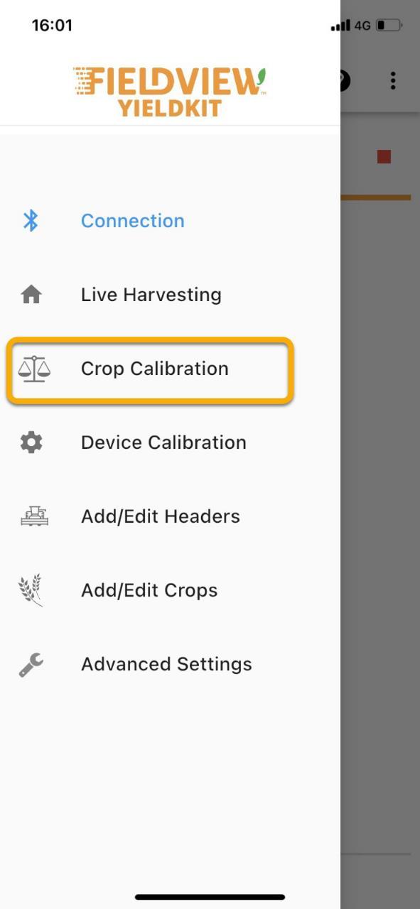
Crop Calibration
1. Navigate to Crop Calibration using the icon
2. Ensure that all listed conditions are met and press their associated boxes on the checklist
3. Press “Start Calibration”
4. Begin harvesting
5. Press as soon as harvest is unloaded
6. Enter measured weight and/or volume, along with measured moisture
7. Press “Complete”
Calibrate Moisture Sensor
1. Obtain a moisture sample while harvesting
2. Press “Edit Average” on the Crop Calibration screen
3. Enter the measured values from the sample
APP BAR
The App Bar is the horizontal, blue bar on the top of most screens in the app. It contains functions that are accessible throughout the app, such as navigation, yield monitor connection status, notifications, help messages, and the day-night mode toggle button.
App Navigation
The navigation drawer allows for easy navigation throughout the app.
1. Press in the top left corner
2. Select the page you would like to go to by pressing on it
Bluetooth™ Connection
The Bluetooth connection status indicates whether a yield monitor is connected to your device. This is shown beside the navigation drawer.
• If a yield monitor is connected, the Bluetooth™ symbol will appear blue and the yield monitor’s name will be shown.
• If there is no yield monitor connected, the Bluetooth™ symbol will appear grey and “Disconnected” will appear instead of the device name.
Notifications are typically error messages from the yield monitor indicating that something is not functioning properly. The notification center will indicate the number of notifications there are to read.
1. Press the icon
2. All notifications will be shown in order of how recent they are
3. Pressing “Clear” will delete all current notifications and leave the notification center
4. Pressing “Dismiss” will leave the notification center
Day-Night Mode
The FarmTRX Mobile App has two separate modes, day mode and night mode. Day mode displays black text on a white background to increase visibility in bright daylight, whereas Night mode displays white text on a gray background to reduce eye strain when harvesting in low light conditions.

1. Press in the top right corner
2. Press “Day-Night Mode” to toggle between day and night mode
Help Messages
To guide the user though the app, most screens have help messages. Help messages provide tutorials and explanations to assist users.
1. Press on the specific part of the app where you would like assistance
2. Press the right side of your screen to progress through the tutorial
3. Press the left side of the screen to go back to a previous step
4. The “skip” button closes the tutorial CONNECTION
This section of the app is used to search for, connect to, and disconnect from Yield ECU.
Searching for yield monitors can be done by pressing the refresh button in the top right corner

1. Press the “CONNECT” button beside the device you would like to connect to

2. Wait for all connecting steps to complete; this may take a moment
3. You will be redirected to the Live Harvesting screen
Disconnecting from a Yield Monitor
1. Press on the Yield Monitor currently connected; a disconnect button should appear below its name
2. Press the disconnect button
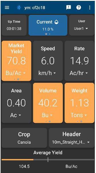
Live Harvesting is used to observe real-time harvest data, such as area covered, current yield, average yield, volume harvested, and weight harvested. Additional harvester information such as speed, rate and uptime are shown. If you have a moisture sensor, current and average moisture will also be available. Crop type and header can be changed on the Live Harvesting screen, as well as userspecific preferences such as layout, values shown, and units.

All values can be shown in a variety of units. To change units:


1. Press the units you would like to change
2. Select desired units
Each card on the Live Screen can be changed to display values the user desires. To change values:
1. Press and hold the card you would like to change; a menu appears showing available values after about 1 second
2. Select the value you want displayed on that card
The Yield Monitor needs to know what crop is being harvested to display accurate data. To change crop type:


1. Press Crop in the bottom left corner
2. Select desired crop
The Yield Monitor needs to know what header is being used to display accurate yield data. To change header:
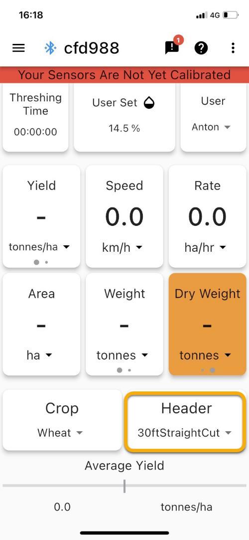
1. Press Header in the bottom right corner; a menu with all headers saved on the device will appear
2. Select desired header
3. To prevent accidental header switching, we require the user to confirm that they want to change headers. Press “Yes” to save your header change
Live Harvesting operates in different modes depending on if a FarmTRX™ Moisture Sensor is connected. If there is no moisture sensor connected, the app allows a manual moisture value to be entered. This allows the user to view the approximate market yield.

If a FieldView Yield Moisture Sensor is connected, live moisture readings are shown. The user may notice a difference between the moisture on the live screen and what is being reported by a bench moisture sensor. This is typically the result of incorrect calibration of the moisture sensor. To calibrate the moisture sensor and manually enter moisture:
1.If a FieldView Yield Moisture Sensor is connected:
a. Long press the blue “Current Moisture” or “Average Moisture” tile in the top center of the screen
b. Use the left Plus/Minus buttons to increases or decrease the adjustment by 1.0
c. Use the right Plus/Minus buttons to increase or decrease the adjustment by 0.1
d. The new moisture value will be shown under “New” in the top right
e. Press “SAVE” when the moisture is properly adjusted
2. If there is no moisture sensor connected:
a. Long press “User Set Moisture”
b. Use the left Plus/Minus buttons to increases or decrease the adjustment by 1.0
c. Use the right Plus/Minus buttons to increase or decrease the adjustment by 0.1

d. The new moisture value will be shown under “New” in the top right
e. Press “SAVE” when the moisture is properly adjusted
Live Harvesting allows the user to view their harvested dry yield volume and weight. The dry values are calculated using the average moisture input by the user.
1. Swipe left on Yield, Volume or Weight
2. The card will turn orange and display the dry values
Both average and current moisture can be seen on the Live Harvesting screen when a FieldView Yield Moisture Sensor is connected.

1. Live Harvesting will default to show the Current Moisture
2. Swipe left on the tile displaying moisture to view Average Moisture
Crop calibrations are done to ensure that the volume and weight measured by the optical sensors of the yield monitor are accurate for each specific crop type.
1. Select the crop that is being calibrated by pressing on the current crop; a list of crops should appear, press on the desired crop

2. Press “START CALIBRATION”
3. Confirm that all conditions specified are met; press the boxes beside each condition
4. Press “READY” when you would like to begin the calibration run

The user can observe elapsed time, area, volume, and weight while completing their calibration run from the calibration screen. They may also use the Live Harvesting screen to monitor the harvest but must remember to return to the Crop Calibration screen to complete the calibration run.

Complete Calibration
Once is pressed, the state of the calibration run is saved allowing the user to navigate elsewhere in the app while waiting for the calibration volume/weight measurement values. It is crucial that the user does NOT press the icon when returning to the Crop Calibration screen to enter calibration values, as this will discard the saved values. After the calibration is complete, the calibration value can be applied to the previously harvested crop.
1. Await measurements for volume and/or weight, and moisture
2. Enter measurements and press “COMPLETE” to apply the calibration Only weight or volume needs to be entered but both is preferred
3. You will be prompted to apply the calibration values to previously harvested area. Choosing to apply calibration to previously harvested crop will apply the calibration value to any yield values made since the last crop change
Calibrating the FieldView Yield ECU and Moisture Sensor system is important to ensure that precise harvest data is gathered by the Yield ECU hardware.
Sensor Calibration determines a baseline measurement of the clean grain elevator to ensure accurate data is gathered from your specific machine.
1. Navigate to Device Calibration using
2. Press “START CALIBRATION” under Sensor Calibration
3. Check the boxes associated with each condition when they are met
4. Press “Ready” to start the calibration
5. When the calibration has finished, press “Complete”
6. If calibration was unsuccessful, an error message will appear:
a. Check that your optical sensors are properly installed, your harvester is stationary and running at full throttle, and the threshing clutch is engaged
b. Press “try again”
Processing delay is the amount of time it takes for the grain entering the system to reach the clean grain elevator. If the delay is not known, a default of 10 seconds will be applied.


1. Press “EDIT DELAY”
2. Enter the machine specific processing delay in seconds
3. Press “Save”
To ensure that the moisture sensor is reporting accurate values, calibrations may need to be done. Users may adjust the moisture sensor’s measurement offset by editing the average moisture. This screen also shows the Moisture Sensor’s firmware version and if the firmware requires an update.


1. Edit average:
a. Press “EDIT AVERAGE”
b. Enter the new average moisture in the “New (%)” field
c. Press “Save”
1. Press “UPDATE FIRMWARE” under Moisture Sensor
2. Wait for the transfer to complete
3. Wait for update to complete
4. If the current firmware version does not match the latest firmware:
a. Power the harvester off for 60 seconds
b. Turn the harvesters power back on
c. Reconnect to the yield monitor
5. If you are unable to press “UPDATE FIRMWARE”, there are no further firmware updates currently available
The yield monitor needs to know what width of land is being harvested for the yield calculation. To avoid requiring the user to enter the header width every time the header is changed, all headers used by the harvester can be entered and saved beforehand. The user can select a header on the Live Harvesting screen.


1. Press the + icon in the top right corner
2. Enter desired Header Name
3. Choose Cut Mode
4. Enter Cut Width
5. To save, press the “Save” button in the top right corner

1. Select the header you would like to delete by pressing on it. The area around the header’s name should turn blue
2. Press the icon in the top right corner
3. Press “Yes” if you would like to delete the selected header
1. Select the header you would like to edit by pressing on it. The area around the header’s name should turn blue
2. Press the icon in the top right corner
3. Enter the desired changes
4. To save, press the “Save” button in the top right corner
The crop list stores several important pieces of data for accurate yield data:

Specific volume is the volume/weight ratio
Yield calibration is the crop specific calibration value that is calculated by Crop Calibration. This can be entered manually but that is not advised
Field Average Moisture is the moisture content measured by the user and is used to show the dry yield, volume and weight in Live Harvesting
Market Moisture is the maximum moisture content that is considered dry by the elevator
1. Press the + icon in the top right corner
2. Enter the name of the crop species
3. Select the category the species belongs to (Cereal, Oil Seed, Pulse, Corn, Other)

4. Enter specific volume; if nothing is entered a default value will be used
5. Enter yield calibration if known; if not a default value will be used until a calibration run is completed
6. To save, press the “Save” button in the top right corner
1. Select the crop you would like to delete by pressing on it; the crop box should turn blue
2. Press the icon in the top right corner
3. Press “Yes” if you would like to delete the selected crop
1. Select the crop you would like to edit by pressing on it; the crop box should turn blue

2. Press the “edit” icon in the top right corner
3. Enter the desired changes
4. To save, press the “Save” button in the top right corner
Advanced Settings allow the user to change machine-specific settings such as the harvester name, enable detailed logging, and change the system language. The user can also restore their device’s crops, headers, and name to the default values. Advanced settings also provide an alternative way to reset the totals that appear on the Live Harvesting screen.

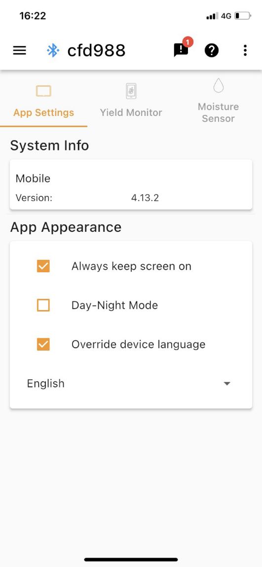
1. Select “Override device language” putting a tick
2. Select your language from the drop-down menu

The yield monitor name that is displayed on the Connection Screen and App Bar can be changed to make it easier to identify for the user.


1. Press the
2. Enter the desired name in the text box
3. Press “Save”
The yield monitor’s name can be returned to the default Device ID.
1. Press the
2. Press “OK” if you would like to reset the device name to default
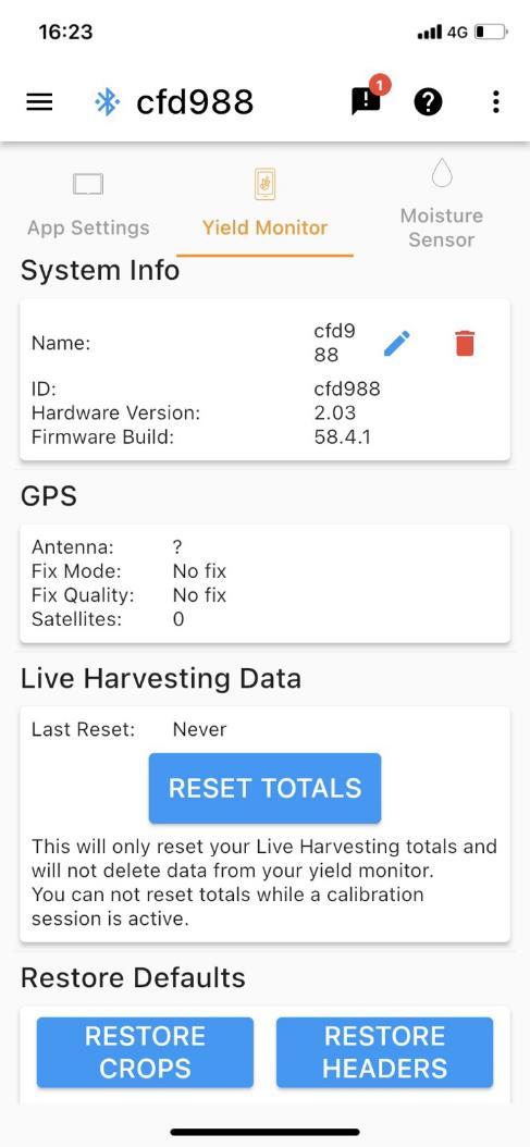
The Live Harvesting totals can be reset without changing the crop type. Doing this will reset Area, Volume, Weight and Average Yield to zero.
1. Press “RESET TOTALS”
2. Press “OK” if you would like to reset the Live Harvesting totals
Restore Configurations
This will reset all configured values and preferences on the yield monitor, essentially resetting it to factory defaults. The values that are reset include crop selection, machine name, processing delay, Live Harvesting totals, Logging level, and Tare.
1. Press “RESTORE CONFIGS”
2. Press “OK” if you would like to reset the values outlined above
Restore Crops
The yield monitor’s crop list can be reset to the 10 default crops and their associated yield values. These crops are: Barley, Canola, Corn, Flax, Lentils, Oats, Peas, Sorghum, Soybeans and Wheat.
1. Press “RESTORE CROPS”
2. Press “OK” if you would like to restore your crop list to default
Restore Headers
The yield monitor’s header list can be reset to the 3 default headers and their associated widths. The defaults are 10m straight cut, 25’ swath and 30’ row headers.
1. Press “RESTORE HEADERS”
2. Press “OK” if you would like to restore your header list to default
Power:
Input voltage/current: 12 Vdc, 3A max
Bluetooth:
Bluetooth® 4.1
Temperature:
Operation -20 °C to 40 °C
Storage -40 °C to 85 °C