Japanese Joinery + Computer Numerical Control
Transposing Marginalized Crafts Traditions and Advanced Fabrication


Throughout Japan you can utter the word kodama and all around you will know it. “The spirit of a tree.” It remains a term still relevant today, undoubtedly a product of the country’s rich history deeply entrenched in a reverence for all things natural.1 Japan is dominated by volcanic soil that hostorically provided little for masons but an endless veriety of trees for carpenters. To no surprise, the vernacular architecture leans heavily timber. Japanese joinery was born of circumstance.1 Iron fasteners were rendered ineffective by Japan’s high humidity, paving the way for the development of tsugite and shiguchi — splicing and connecting joints that do not rely on glue, nails, or screws.1
The first examples of Japanese joinery can be found dating back to 3000 BCE with the construction of simple timber stuctures framed over pits and covered in thatching, though it was not until the advent of iron tools in the Yayoi period (250 BCE-200 CE) that Japanese joinery, as we know it today, began to take form. Over the next millenium, family guilds organized with each specializing in different typologies, and the unification of the country under a single banner fostered the spread of information and techniques throughout. Consequently, the varied design and engineering requirements of the many types of structures resulted in hundreds of distintcly different joints, many of which remained largely out of reach of the public domain.2 The guild system was fiercly competitive and perpetuated a culture of guild trade secrets, the effects of which can still be seen today. Though, at the core of these guilds still remained the craft, one of which its craftsmen showed immense respect.
The Japanese carpenter did not enter an apprenticeship, he entered a way of life. From the moment a tree was felled, a strict and disciplined process began that echoed the care and beauty clearly visible in a completed joint. This same reverence can also be found in the tools used to fashion the wood. Historically, a carpenter’s instruments were refered to as dogu, or “instruments of the Way”. The word tool did not show adequate respect to the means of the craft, but rather demoted it.2
Traditional joinery would continue to dominate the architectural landscape in Japan up until the Second Industrial Revolution.


The history of computer numerical control can be traced back to 1775 when John Wilkinson invented the first machine tool. A simple design, by today’s standards, that bore cylinders for steam engines set off a cascade of innovation. Contemperaneously, Joseph Jacquard was laying the foundations for modern computing by revolutionizing the loom industry. He found a way to control looms by encoding data on paper cards through a series of punched holes.1 Analog systems would continue to develop over the next two centuries, but it was not until 1952 that the real revolution began behind the innovation of the father of numerical control himself, John T. Parsons.
Parsons, in conjunction with the Massachusetts Institute of Technology (MIT), would for the first time ever wire a digital computer to a milling machine. This, by definition, created the first numerically controlled machine tool. By replacing a machinist with a computer program, the team was able to produce aircraft components more complex than by any means otherwise.2 By 1972, the development of Computer Aided Design (CAD) and Computer Aided Machining (CAM) pushed the fabrication method further, though it wasn’t until 1976 when 3D computer-aided design were incorporated into CNC machining. Further still, the technology continued to grow with the launch of the Enhanced Machine Controller project, or LinuxCNC, that enabled general purpose computers to run personal CNC machines.3
Today, CNC machines can work in up to 6 axes and can cut a plethora of materials. It can be assumed with great certainty that almost every commercial product on the market has been directly or indirectly touched by CNC machining.
1 Mohammadi, Goli. “History of CNC Machining.” Medium, April 12, 2019. https://medium.com/cnc-life/history-of-cnc-machining-part-12a4b290d994d
2 Gershenfeld, Neil. “How to Make Almost Anything: The Digital Fabrication Revolution.” Foreign Affairs 91, no. 6 (November 1, 2012): 43–57. https://search.ebscohost.com/login.aspx?direct=true&AuthType=ip,shib&db=edshol&AN=edshol.hein.journals. fora91.114&site=eds-live&scope=site.
3 Bethany. “How CAD Has Evolved Since 1982.” Scan2CAD, June 28, 2019. https://www.scan2cad.com/blog/cad/cad-evolvedsince-1982/


Current Status: Japanese Joinery
Although beautiful and resilient, Japanese joinery has become less common in the modern architectural landscape. The advent of mass prodution and the industrial revolution rendered many time consuming crafts obsolete in a society now concerned with economic growth and efficiency at scale. Nevertheless, the craft is still practiced sparingly as a construction method, but remains more common in furniture and small craft design. Some modern works take inspiration from the traditonal craft, though the heavy lifiting of structure is now typically left to concrete and steel.1 Most notably, Kengo Kuma used tsugite as a central element in the design of the Prostho Museum Research Center in Kasugai-shi, Japan.

Current Status: CNC Routing
Whether you know it or not, almost every commercial product that you own has been directly or indirectly fabricated by a numerically controlled machine. Everything from laptop cases to tools that mold mass produced goods are touched by fabrication method.2 Today, CNC machines have advanced far beyond the machines of old. 5-axis machines are at the cutting edge, fabricating extremely detailed geometries at incredible speeds. The increasing intuitiveness of CAD and CAM softwares has increased efficiency and accuracy, while also seamlessly integrating into the machine platform that run them. This has lowered the barrier of entry to understand and operate what used to be much more technical machinery.3
2 Gershenfeld, Neil. “How to Make Almost Anything: The Digital Fabrication Revolution.” Foreign Affairs 91, no. 6 (November 1, 2012): 43–57. https://search.ebscohost. com/login.aspx?direct=true&AuthType=ip,shib&db=edshol&AN=edshol.hein.journals. fora91.114&site=eds-live&scope=site.
3 Fast Radius. “5 CNC Machining Trends to Watch Out for in 2021.” Fast Radius. November 30, 2020. https://www.fastradius.com/resources/cnc-machining-trends-2021/


Process: Japanese Joinery
From selecting the wood to hammering in the final tenon, the Japanese carpenter follows a detailed process that focuses less on the end result and more on the process itself. In The Complete Japanese Joinery, Hideo Sato tells us:
“
...one should truly enjoy one’s work. It is also important to remember that wood is a living thing — one must understand its properties and not oppose them. Whenever work is forced, it either ruins the piece, damages the tools, or injures the worker, so work must always be done with the utmost care.”1
Despite the immense amount of training and technique required to construct even one joint, Japanese joinery can be viewed as a philosphy just as quickly as it can a technical craft. This is an important distinction to note. For the purposes of this brief, the following will outline the construction of one joint and will exclude much of the early steps involved in processing the lumber, as this research is more narrowly focused on the joinery crafts of tsugite and saguchi.
Kanawa Tsugi Blind dadoed, rabbetted and keyed scarf joint. This is a common end joint for girders and the base of columns.

i. Draw cut lines
ii. Ripsaw kerf along A to intersect B
iii. Cut along B and C to intersect D with a crosscut saw

Scarf joint step 1 (Sato 1995)
Scarf joint step 2 (Sato 1995)
iv. Chisel out from C to B. Then make a rip saw kerf at E
v. Finish chiselling the notch to line F
vi. Slope kerf with rip saw on both sides
vii. Chisel diagonally where marked
Scarf joint step 3(Sato 1995)


vi. Rip saw kerf along J to intersect F
vii. Chisel diagonally where marked
viii. Assemble
Scarf joint step 4 (Sato 1995)
Although the process is vastly more advance, computer numberical control design can be broken down into 3 basic parts — input, process, and output. A computer, the input, is used to design what is to be routed using CAD or CAM softwares. Next, an interface, or the process, connecting the software to the CNC machine is used to break down the input into a set of coordinates that the CNC mahcine can use to cut materials. The CNC machine, or the output, uses the signals generated by the interface to move in the X, Y, and Z directions to cut the materials placed on the machine.1 Of course, as it is with all things, the actual process is not so simple. The following pages of this section will demonstrate the process used to generate the first joint as part of this research.
i. Generate a 3d model within the parameters of the CNC machine
ii. Break the model into the individual parts required for the output

2. Process
i. Calibrate interface to to desired specifications — drill speed, offset, dogbone, etc...


ii. Set 0 point for drill path
iii. Convert 3d model to data set to generate drill path
3. Output
i. Set up vice to desired specifications
ii. Achor material in place
iii. Run drill path, all members
iv. Sand output
v. Assemble
Craft: Japanese Joinery
• Subtractive
• Time intensive
• Use of multiple tools
• Requires years of experience
• Human error
• Square tools
• Squared corners
• Expensive
• Tools intended for one material
• Full range of motion
Synergies:
Advanced Fabrication: CNC Routing
• Subtractive
• Efficient
• One tool
• Low barrier of entry
• Precise to 1/1000”
• Circular drill bit
• Rounded corners
• Cost effective
• Tool intended for multiple materials
• 3-axis
The two methods share little in common other than the obvious fact that they are both subtractive means of fabrication. Although this does not present ample opportunity, it does align the two methods within a common structure.
Bottlenecks and Opportunity:
Japanese joinery, though a beautiful and worth while craft, requires an amount of time and energy not suited for the 21st century. CNC routing can address the shortcomings of the craft through efficient and cost effective fabrication. Time spent on one joint through traditional means would yield dozens through advanced fabrication. CNC routing also requires the use of circular bits, limiting the range of motion at interior corners. Consequently, CNC joints are more effectively joined through curved or filleted edges, a geometry not easily replicable with hand tools. On the other hand, hand tools allow the carpenter to produce joints through subtraction at multiple planes. The capabilities of a 3-axis CNC machine does not.
Needs:
• Rhino 7
• CNC machine
• Wood shop
• 2x2 poplar
• 4x4 poplar, oak
• Resin blocks
Exploration: Setup
Shop Sabre 4896 Triple-Axis CNC


The half lapped gooseneck joint is also used to extend mudsills and roof joists. As is with many Japanese joints, the dimensions of the various cuts are based on shared proportions. Due to the size of my material, it was necessary to widen the “neck” of the joint to maintain structural integrity during the routing of the wood.


half lapped gooseneck joint


Top Scale: 1/4”=1’-0”
Exploded Isometric Scale: 1/2”=1’-0”

Isometric Scale: 1/4”=1’-0”
Bottom Scale: 1/4”=1’-0”
required a forced mill due to its’ size
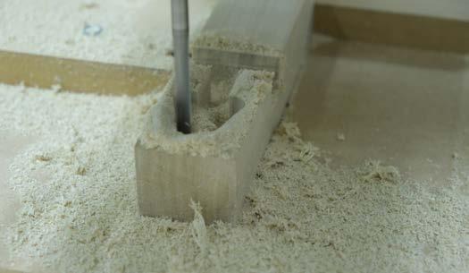
The CNC machine cannot cut 90 degree angels at interior corners, so all corners are radiused. The curves must be modeled to ensure precision.

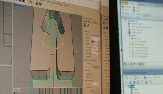

Exploration: Replication
The half lapped dovetail joint is commonly used for mudsills and roof joists as an extending joint. A lap or hip is made at the midpoint of the wood member to join the male and female pieces.
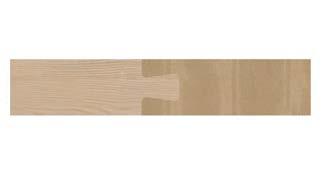

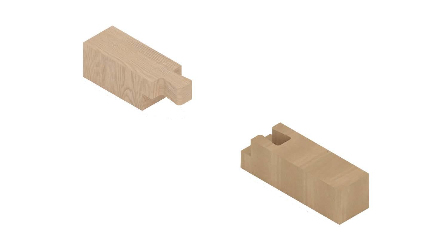

Top Scale: 1/4”=1’-0”
Exploded Isometric Scale: 1/2”=1’-0”

Isometric Scale: 1/4”=1’-0”
Bottom Scale: 1/4”=1’-0”


The scarf joint is commonly used as an end joint. Male and female members are identical and slide together leaving space for a tenon to lock the two members in place. The proportions of this joint also required adjustments to satisfy the patameters of the CNC machine. Isometric Scale: 1/4”=1’-0”


Top Scale: 1/4”=1’-0”
Bottom Scale: 1/4”=1’-0”
Exploded Isometric Scale: 1/2”=1’-0”

Joint too tight, tolerance required to allow disassembly. Adjustments required to cut speed and bit size to improve cut quality.


Exploration: Iterative
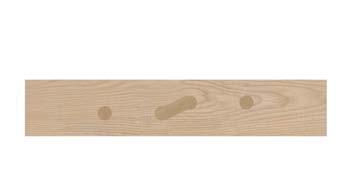
The caterpillar design is a direct result of the CNC milling parameter requiring curved corners. The joint is loosely based on the half blind scarf joint and maintains curved corners on the x-axis only.


Isometric Scale: 1/4”=1’-0”
Top Scale: 1/4”=1’-0”
Bottom Scale: 1/4”=1’-0”
Exploded Isometric Scale: 1/2”=1’-0”

Caterpillar disassembled, points must be carefully moderated to avoid breakage, tenons should be 1/2” minimum


Exploration: Iterative
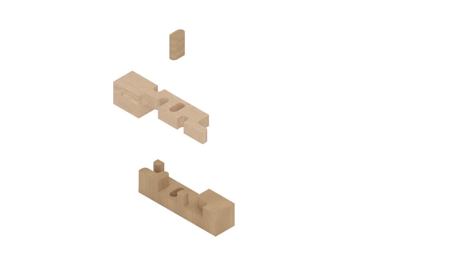
Similar to the caterpiller, the swiss tenon is an exploration of the geometry encouraged by the parameters of the CNC machine. Curver are maintained in the x-axis at intervals set by a grid.


Exploded Isometric Scale: 1/2”=1’-0”

Isometric Scale: 1/4”=1’-0”
Bottom Scale: 1/4”=1’-0”
Top Scale: 1/4”=1’-0”


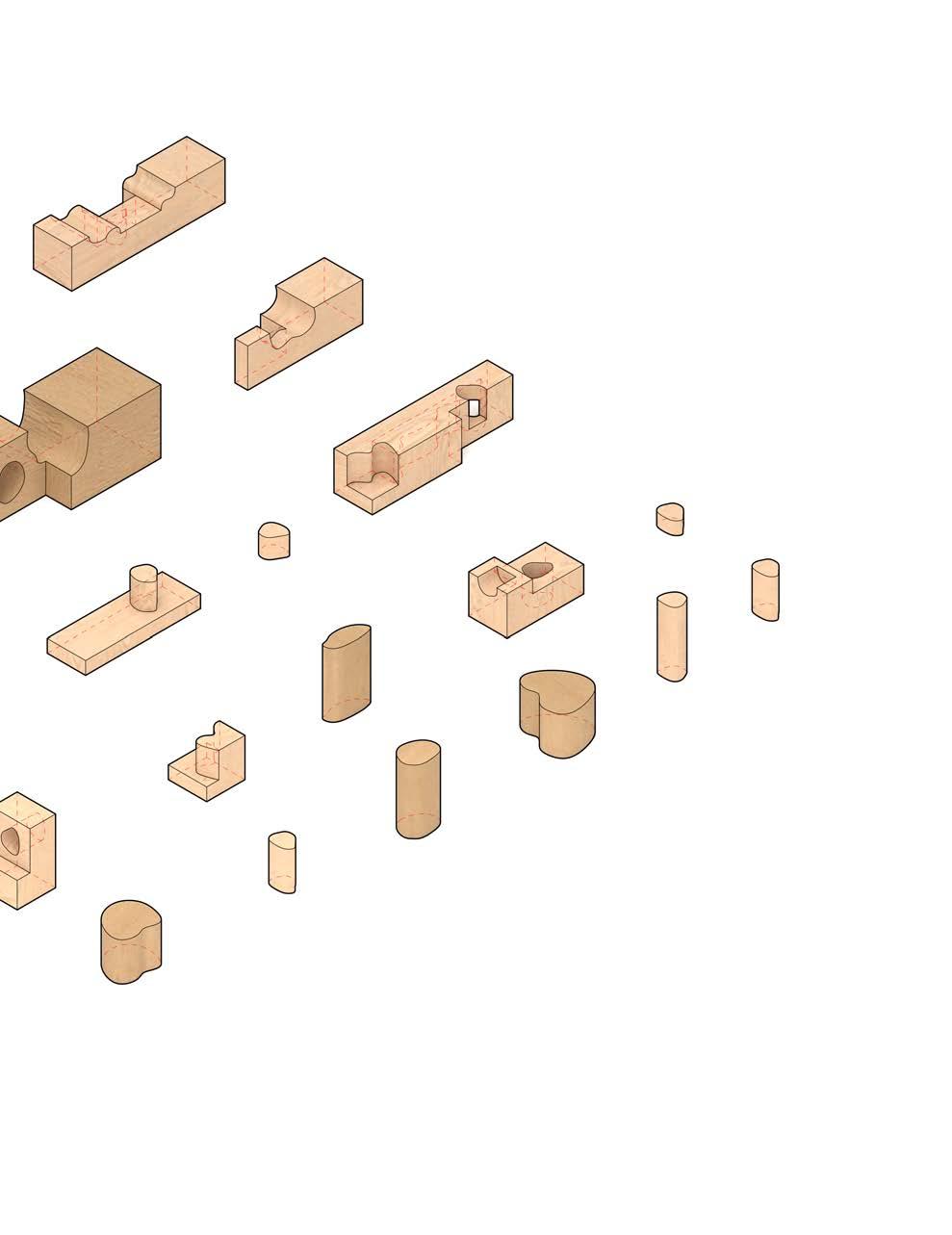
The puzzle cube is a prototype derived from the research done throughout the exploration process. The geometry of the cube leverages the capabilities of the CNC router by incorporating more daring curves on multiple faces of each member. The cube is 6” x 6” x 6” and is composed of 26 individual pieces of oak and poplar. Tenons of various sizes are used to hold key members in place and ensure the cube’s structural integrity. The prototype begins to describe spatial relationships as member may be removed to create negative space.

Isometric Scale: 1/2”=1’-0”

Tenons of various sizes


Multiple faces routed per piece

gooseneck and dovetail derivative
Isometric Disassembled Scale: 1/4”=1’-0”

The translation to form is relatively linear. The parameter set outlined in the preceding research is leveraged to create a form congruent with the program. The massing begins with two equal cubes that are split similarly to the puzzle cube. The origin of dissasembled pieces is easily discernable, allowing for dynamic shifting and rotation as deemed necessary. The curves generated from the fabrication process of the early models and prototype are integrated at interior corners of dissasembled pieces of the massing. This creates a clear and direct throughline from the research to its’ architectural realization. Similar to the exterior form, the interior will follow the same organizational logic and set of parameters. The building will be in and of itself a puzzle cube, using subtraction and dynamic assemblies to meet programatic requirements.


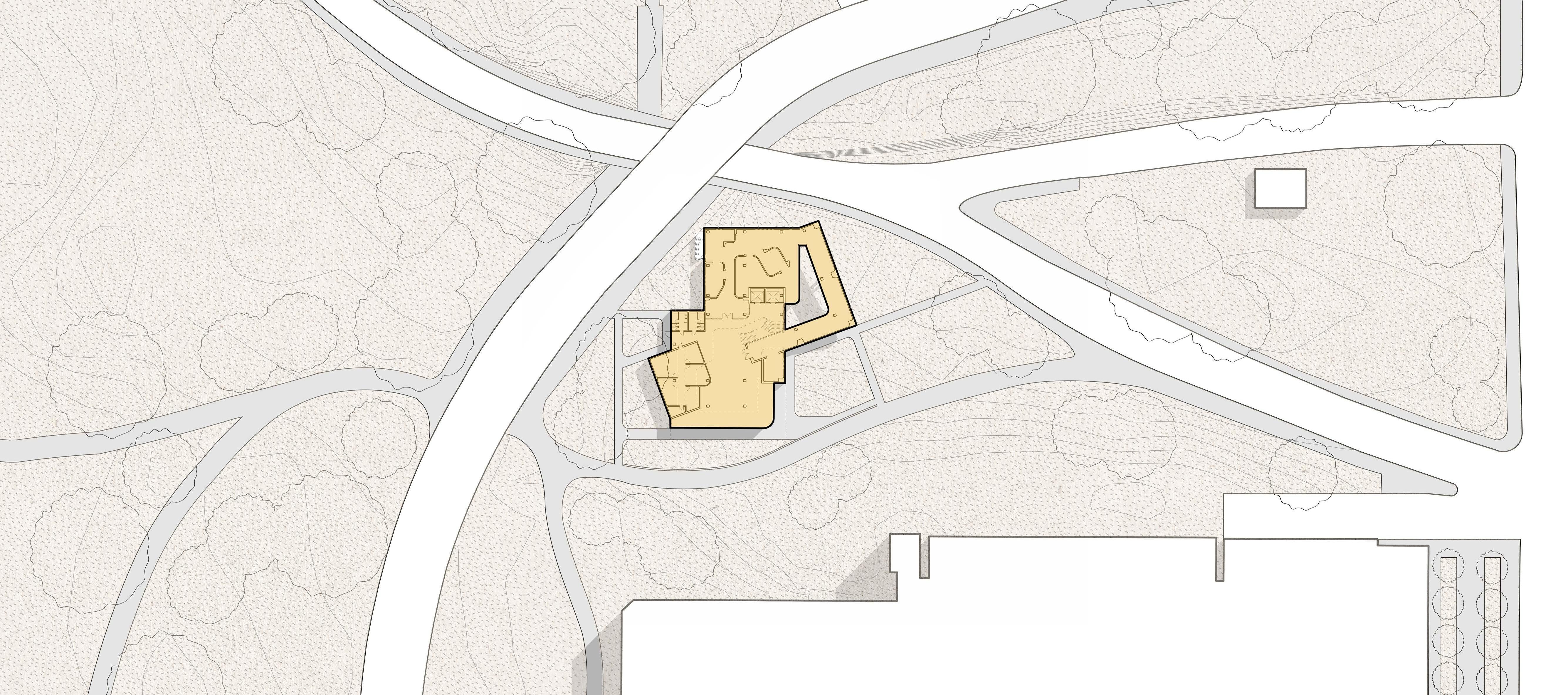

 First Floor Plan: 1/64” = 1’-0”
1. Entry/Atrium
2. Offices
3. Men’s Bathroom
4. Women’s Bathroom
South Elevation: 1/64” = 1’-0”
North Elevation: 1/64” = 1’-0”


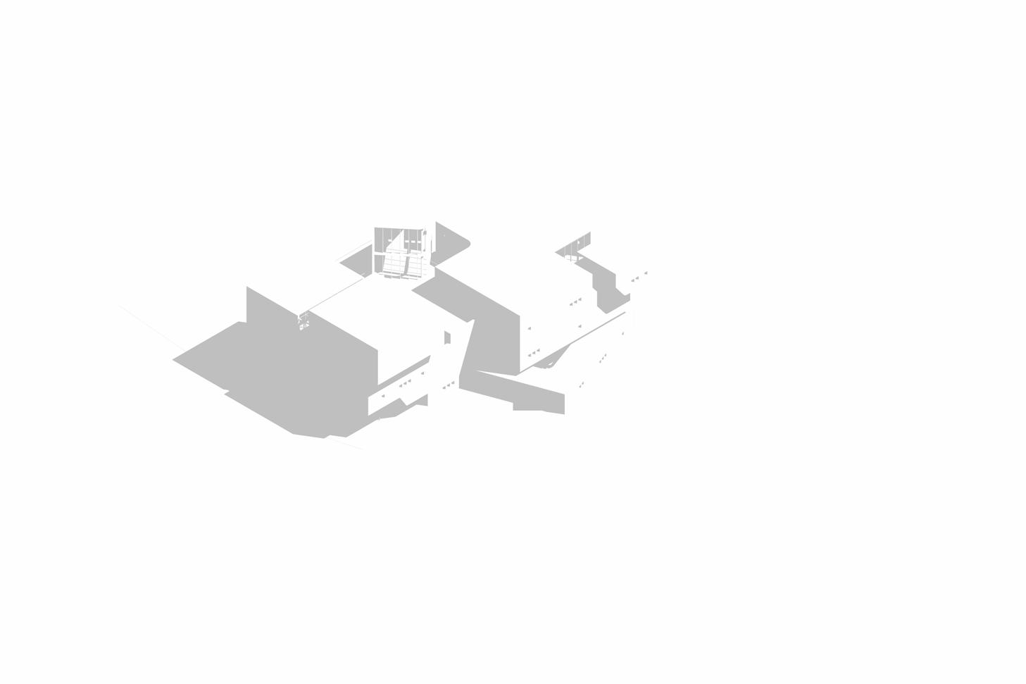

From Southwest

From Southeast


Traditional craft and advanced fabrication should not be at odds. It is without question that they are at opposite ends of the spectrum, but why is it that one cannot inform the other? This project aims to blend the old with the new in a way that revitalises the spirit of tradional Japanese joinery. The methodologies employed to do so will challenge the efficacy of both disciplines to ensure a rigorous output. The parameters of the CNC router present a unique opportunity to explore more complex geometries not feasible with hand tools. The curved edge will be leveraged in both the x and y axes to better suit the advanced fabrication method and potentially develop a novel tectonic system.
References:
Seike Kiyoshi Yuriko Yobuko and Rebecca M Davis. 1977. The Art of Japanese Joinery First ed. New York: J. Weatherhill.
Nii Koichi Paul Yasuo Nakahara and Hideo Sato. 1995. The Complete Japanese Joinery. Point Roberts WA: Hartley & Marks.
Mohammadi, Goli. “History of CNC Machining.” Medium, April 12, 2019. https://medium.com/cnc-life/ history-of-cnc-machining-part-1-2a4b290d994d
Gershenfeld, Neil. “How to Make Almost Anything: The Digital Fabrication Revolution.” Foreign Affairs 91, no. 6 (November 1, 2012): 43–57. https:// search.ebscohost.com/login.aspx?direct=true&AuthType=ip,shib&db=edshol&AN=edshol.hein.journals. fora91.114&site=eds-live&scope=site.
Fast Radius. “5 CNC Machining Trends to Watch
Out for in 2021.” Fast Radius. November 30, 2020. https://www.fastradius.com/resources/cnc-machining-trends-2021/
Cole Lubchenko. “7 Things You Need to Know About Japanese Joinery.” Japan Objects. August 20, 2021. https://japanobjects.com/features/japanese-joinery.
Giant Cypress. January 3, 2014. https://giantcypress.net/post/72076590701/article-from-the-january-1967-issue-of-popular
Rethink Tokyo. “Tsugite: The Tetris of Japanese Joinery.” Rethink Tokyo. August 8, 2018. https://www. rethinktokyo.com/2018/08/08/tsugite-japanese-joinery-wood
Is Japan Cool? “Buddhist art of Horyu-ji Temple.” Is Japan Cool? 2021. https://www.ana-cooljapan.com/ destinations/nara/buddhistartofhoryu-jitemple
Deans, Marti. “How to Select a 5-Axis CNC Mill for Mold Making.” Autodesk. March 24, 2021. https:// www.autodesk.com/products/fusion-360/blog/select5-axis-cnc-mill-mold-making/
Bethany. “How CAD Has Evolved since 1982.” Scan2CAD. June 28, 2019. https://www.scan2cad.com/ blog/cad/cad-evolved-since-1982/
Advancing Craft: A translation to modern tectonics. 2020. Accessed October 17, 2022. https:// search.ebscohost.com/login.aspx?direct=true&AuthType=ip,shib&db=edsoai&AN=edsoai. on1224565172&site=eds-live&scope=site
Finding the Key: Designing Timber Connections for CLT Panels. 2019. Accessed October 17, 2022. https://search.ebscohost.com/login.aspx?direct=true&AuthType=ip,shib&db=edsoai&AN=edsoai.on1155918750&site=eds-live&scope=site
Maria Larsson, “Tsugite: Interactive Design and Fabrication of Wood Joints,” accessed October 17, 2022, http://ma-la.com/tsugite.html.